US7811203B2 - Walker behavior detection apparatus - Google Patents
Walker behavior detection apparatusDownload PDFInfo
- Publication number
- US7811203B2 US7811203B2US11/528,329US52832906AUS7811203B2US 7811203 B2US7811203 B2US 7811203B2US 52832906 AUS52832906 AUS 52832906AUS 7811203 B2US7811203 B2US 7811203B2
- Authority
- US
- United States
- Prior art keywords
- walker
- behavior
- walking
- detecting
- variation
- Prior art date
- Legal status (The legal status is an assumption and is not a legal conclusion. Google has not performed a legal analysis and makes no representation as to the accuracy of the status listed.)
- Expired - Fee Related
Links
Images


Classifications
- G—PHYSICS
- G01—MEASURING; TESTING
- G01C—MEASURING DISTANCES, LEVELS OR BEARINGS; SURVEYING; NAVIGATION; GYROSCOPIC INSTRUMENTS; PHOTOGRAMMETRY OR VIDEOGRAMMETRY
- G01C22/00—Measuring distance traversed on the ground by vehicles, persons, animals or other moving solid bodies, e.g. using odometers, using pedometers
- G01C22/006—Pedometers
- G—PHYSICS
- G06—COMPUTING OR CALCULATING; COUNTING
- G06V—IMAGE OR VIDEO RECOGNITION OR UNDERSTANDING
- G06V40/00—Recognition of biometric, human-related or animal-related patterns in image or video data
- G06V40/20—Movements or behaviour, e.g. gesture recognition
- G06V40/23—Recognition of whole body movements, e.g. for sport training
- A—HUMAN NECESSITIES
- A61—MEDICAL OR VETERINARY SCIENCE; HYGIENE
- A61B—DIAGNOSIS; SURGERY; IDENTIFICATION
- A61B2560/00—Constructional details of operational features of apparatus; Accessories for medical measuring apparatus
- A61B2560/02—Operational features
- A61B2560/0242—Operational features adapted to measure environmental factors, e.g. temperature, pollution
- A—HUMAN NECESSITIES
- A61—MEDICAL OR VETERINARY SCIENCE; HYGIENE
- A61B—DIAGNOSIS; SURGERY; IDENTIFICATION
- A61B5/00—Measuring for diagnostic purposes; Identification of persons
- A61B5/103—Measuring devices for testing the shape, pattern, colour, size or movement of the body or parts thereof, for diagnostic purposes
- A61B5/11—Measuring movement of the entire body or parts thereof, e.g. head or hand tremor or mobility of a limb
- A61B5/1112—Global tracking of patients, e.g. by using GPS
Definitions
- the present inventionrelates to a walker behavior detection apparatus.
- a walking statusis recognized by observing vertical movement accompanying walking using an acceleration sensor and spectrum-analyzing the vertical movement.
- Japanese Laid-open Patent Application Publication No. 10-113343discloses such a technology.
- a position of a walkeris estimated in accordance with the recognized walking status by comparing the detected walking status with geographic data of, for example, passages in a building or roads outside the building.
- a moving distanceis calculated by estimating stride from the recognized walking status.
- Japanese Laid-open Patent Application Publication No. 2004-085511 and Journal of paper A by the Institute of Electronics, Information and Communication Engineers, Vol. J87-A, No. 1, pp 78-86, January 2004disclose such a technology.
- the walking statusis recognized by observing physical forces (an acceleration, an angular velocity, and like) generated by a movement of a walker.
- Walking on a staircasecan be recognized only by the acceleration and the angular velocity from a waveform observed during the walking on the staircase.
- walking on the staircasemay be erroneously recognized as walking on a level which resembles walking on the staircase.
- the erroneous recognitionmay cause judgment that the position is at an incorrect place.
- the prior art position determination methoddoes not consider a walking direction of the walker.
- the moving distanceis calculated by estimating a stride. However, it does not consider moving distances during climbing and descending the staircase.
- a first aspect of the present inventionprovides a walker behavior detection apparatus comprising: detecting means for detecting a horizontal walking behavior of a walker regarding a level; altitude variation detecting means for detecting altitude variation of the walker; and estimating means for estimating a walking behavior of the walker on the basis of a combination of the horizontal walking behavior and the detected altitude variation.
- a second aspect of the present inventionprovides a walker behavior detection apparatus comprising: walker behavior detecting means for detecting a behavior of a walker; a storage for storing geographical information corresponding to the detected behavior of the walker; and searching means for searching a part of the geographical information corresponding to the detected behavior of the walker to detect position information and traveling direction information on the basis of the searched part.
- FIG. 1is a block diagram of a walker behavior detection apparatus according to a first embodiment of the present invention
- FIG. 2shows a flowchart of the walker behavior detection apparatus according to the first embodiment
- FIG. 3is a classifying table according to the first embodiment
- FIG. 4Ais a graphical drawing for showing an example of altitude estimation according to the first embodiment
- FIG. 4Bis a graphical drawing for showing an example of behavior judgment regarding the result in FIG. 4A ;
- FIG. 5is a classifying table according to the first embodiment in which the number of recognition classes is increased
- FIG. 6is a table for stride estimation according to a second embodiment
- FIG. 7is a block diagram of the behavior detection apparatus for estimating the stride and detecting a position according to the second embodiment of the present invention.
- FIG. 8is an illustration for operation during the movement on a staircase referred in the second embodiment and a third embodiment
- FIG. 9shows a flowchart of altitude compensation using the walker behavior detection apparatus according to a modification in the first embodiment
- FIG. 10is a block diagram of the behavior detection apparatus according to the third embodiment of the present invention.
- FIG. 11shows a flowchart of position and traveling direction detection using the walker behavior detection apparatus, according to a fourth embodiment
- FIG. 12is an illustration of an example of a moving locus without compensation according to the second embodiment for comparison in the fourth embodiment
- FIG. 13is an illustration for showing a result of the operation according to the fourth embodiment in the case of the same movement of the walker as that shown in FIG. 12 ;
- FIG. 14is a block diagram of a walker navigation terminal using the walker behavior detection apparatus according to a fifth embodiment
- FIG. 15is a block diagram of a walker navigation terminal using the walker behavior detection apparatus according to a modification in the fifth embodiment.
- FIG. 16is a block diagram of a worker status detection system using the walker behavior detection apparatus according to a sixth embodiment.
- the present inventionprovides a walker behavior detection apparatus capable of accurately recognizing a walking status though the walker is in a walking status with vertical movement.
- a behavior of a walkeris recognized using a combination of recognizing a walking behavior on a level and simultaneously detecting vertical movement to improve a recognition accuracy.
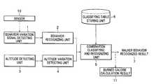
- FIG. 1is a block diagram of a walker behavior detection apparatus according to a first embodiment of the present invention.
- a behavior variation signal detecting unit 1detects a behavior variation signal.
- the behavior variation signalis a signal generated by a sensor 10 for detecting an acceleration variation accompanying a movement of the walker, or a signal of an angular velocity, a displacement of a joint of the walker, a variation in an intensity of an electric field transmitted by a base station according to a position or the movement of the walker, a gyration variation of the walker, or the like.
- a behavior recognizing unit 2recognizes a behavior or a variation of the behavior such as “walking” and “running” of the walker.
- the behavior variation signal detecting unit 1for example, an acceleration sensor (for example, see FIGS. 14 to 16 ) is available for detecting upward and downward acceleration variation accompanying the behavior of the walker, and the behavior recognizing unit 2 recognizes the behavior variation of the walker such as “walking” and “running” from an amount of characteristic derived by frequency-analyzing the behavior variation signal.
- a receivercarried by the walker, for receiving a radio wave transmitted from the base station is also available.
- the behavior recognizing unit 2may recognize the behavior and/or the variation in the behavior of the walker using an amount of characteristic of a variation in a waveform of an electric field intensity of a radio wave observed while the walker moves.
- An altitude detecting unit 3detects an altitude of the walker.
- a barometric pressure sensorfor example, see FIG. 15
- the altitude detecting unit 3may detect an altitude using altitude information obtained by a satellite positioning unit such as a GPS (Global Positioning System) unit (for example, see FIG. 14 ) or an altitude by referring to a table indicating correspondence between ID information of an RFID or a wireless beacon and the previously measured altitude information.
- An altitude variation detecting unit 4detects a variation in the altitude of the walker, i.e., a variation in the altitude per unit time interval.
- an altitude variationis detected by differentiating a barometric pressure data observed with the barometric pressure sensor per unit time interval.
- a combination classifying and recognizing unit 5classifies the results from the behavior recognizing unit 2 and the altitude variation detecting unit 4 with a classifying table stored in a classifying table storing unit 6 to output a walker behavior recognition result 7 of the walker.
- FIG. 2With reference to FIG. 2 , will be described a flow of a process in the walker behavior detection apparatus.
- various types of unitsare available for the behavior variation signal detecting unit 1 and the altitude detecting unit 3 .
- the accelerationis detected as the behavior detection signal
- the barometric pressure sensoris used as the altitude detecting unit 3 .
- a value of the acceleration sensoris inputted in a step 21 .
- an analog signal outputted by the acceleration sensoris read with an A/D converter.
- the read value of the acceleration sensoris converted into a frequency domain with an FFT (fast Fourier transform) or the like in a step 22 .
- a frequency in a spectrum indicating a pace of the walker(pace spectrum) is extracted from data obtained by converting the output of the acceleration sensor into the frequency domain and intensities are detected.
- the intensity of the spectrum at the frequencyis classified with a membership function to recognize the behavior of the walker such as “walking” and “running” with the membership function (similar to the recognizing unit disclosed in Japanese Laid-open Patent Application Publication No. 10-113343).
- the behavior of the walkeris recognized with an assumption that the walker moves on a level.
- a value of the barometric pressure sensoris read with an A/D converter at the same time as in the acceleration sensor.
- the entered value of the barometric pressure sensoris calculated by differentiating at a unit time interval in the step 26 to convert it into a variation in the barometric pressure (barometric pressure variation).
- a walking behavioris recognized by combining two types of judging results from the recognizing result in the step 24 of the walking behavior and the calculation result of the barometric pressure variation in the step 26 .
- the following processis executed.
- the barometric pressure variationbecomes that linked to a sea level pressure at that moment.
- the barometric pressuremay rapidly vary because a depression or a typhoon passes, the variation is equal to or less than several hPa.
- a maximum barometric pressure variation at Yokohama when typhoon No. 11 of 2005 passeswas 5.1 hPa for one hour from 3:00 a.m. to 4:00 a.m. on (August) 26 .
- the barometric variationis converted into an altitude variation, the value is about 43 m per hour.
- the barometric variationis considered to be an altitude variation of about 70 cm per minute.
- the walkerwhen the walker climbs a staircase, the walker generally moves across about 4 m of one floor in about 10 to 15 seconds. Thus, the walker moves about 16 m for one minute.
- the barometric variation by the movement of the walkeris about twenty times that by the approaching typhoon. Accordingly, the movement can be judged as vertical movement using the barometric variation with a threshold. When the barometric variation is smaller than the threshold, the movement can be judged as a movement on the level.
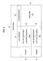
- the abscissa 32represents types of walking behavior and the ordinate 31 represents an altitude variation (barometric pressure variation).
- a numeral 38represents the threshold for judgment between presence and absence of the vertical movement in the barometric variation.
- a level movement region 36 under the threshold 38 with a small barometric variationrepresents the absence of the vertical movement as a level movement.
- a vertical movement region 37 above the threshold 38 with a large barometric variationrepresents the presence of the vertical movement.
- the walking behavior of the walkeris judged by a combination of the judgment based on the barometric pressure and the judgment made in the step 24 .
- the judgment in the step 24is made regarding the abscissa 32 in FIG. 3 .
- references 39 a and 39 brepresent thresholds for types of the behavior of the walker.
- On the left side of the threshold 39 ais a rest region 33 .
- On the right side of the threshold 39 bis a running region 35 .
- Between the thresholds 39 a and 39 bis a walking region 34 .
- the behavior of the walkeris judged as a rest on the level (classified into a rest-on-level region 301 ), at an overlapped region between the level movement and a status of rest on the level.
- the barometric pressure variationis judged as the level movement (classified into a level movement region 36 ) and the type of the behavior is judged as walking (classified into the walking region 34 )
- the walking behavior of the walkeris judged as walking on the level (classified into a walking-on-level region 302 ).
- the walking behavior of the walkeris judged as walking on the level (a walking-on-level region 302 ).
- the type of the behavioris judged as running (the running region 35 )
- the walking behavior of the walkeris judged as running on the level (a running-on-level region 303 ).
- the walking behavior of the walkeris judged as movement on an elevator (elevator movement region 304 ).
- the behavior of the walkeris judged as walking on a staircase (walking-on-staircase region 305 ).
- the behavior of the walkeris judged as running on the staircase (running-on-staircase region 306 ).
- the recognition resultis outputted in the step 28 .
- FIGS. 4A and 4Bshow an example of judgment. Abscissas represent time.
- a waveform 40represents barometric pressure data and the ordinate on the left side in FIG. 4A represents AD-converted values and the ordinate on the right side in FIG. 4A represents altitudes after conversion.
- the output of the barometric pressure sensoris A/D-converted after conversion of the output such that a conversion output increases in value as the pressure decreases as the altitude increases and decreases as the pressure increases as the altitude decreases.
- a waveform 42indicates intensities of pace spectrum extracted in the step 23 .
- the ordinate on the left side in FIG. 4Brepresents spectrum intensities.
- the behavioris judged as the walking status, and when the spectrum intensity exceeds 0.4, the behavior is judged as the running status.
- a waveform 41represents a judging result read on an ordinate on the right of FIG. 4B .
- the behavior of the walker between 0 and 20 secondsis judged as a rest status.
- there is substantially no barometric pressure variationbecause the intensity 42 of the pace spectrum is approximately from 0.05 to 0.1 (the walking status). Then, there is no barometric pressure variation with the walking status and thus judged as walking on the level.
- there is a barometric variation and the statusis a rest.
- the behavioris judged as movement by an elevator.
- the barometric pressure variationhas a positive variation and thus, indicates the walking status from the pace spectrum. Thus, the walker is judged to climb the staircase.
- the barometric pressure variationis negative and the status of the walker is judged as walking, so that the walker is judged to be descent on a staircase.
- the walking status accompanied by the vertical movementcan be recognized by combining the recognition in the behavior recognizing unit 2 and the recognition on the basis of barometric pressure variation in the altitude variation detecting unit 4 .
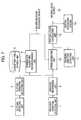
- FIG. 5shows a modification in which the thresholds for the altitude variation are more than those in FIG. 3 and threshold functions are inclined in accordance with severity of the walking action (the running is severer than the walking) to discriminate more behaviors of the walker.
- a slope and an escalatorare added to the staircase as the vertical movement to be recognized.
- the threshold value 501is for recognizing the walker in a rest on an escalator
- the threshold value 502is for recognizing the walker in a rest on the elevator. Between the thresholds 501 and 502 the behavior is classified into a moving on an escalator without walking (motionless-on-escalator region).
- the threshold values 501 and 502are determined by ascending speeds of the escalator and the elevator, respectively. If the movement is accompanies a walking action, in which case altitude ascending variation by the walking should be additionally considered, a threshold of the barometric pressure variation should be determined in consideration of severity of walking in addition to the ascending variation by the escalator.
- threshold lines 504 and 505 for the barometric pressurehave values becoming large as the behavior of the walker becomes running. Discrimination of the behavior of the walker is made from a relation between the result recognized in the step 24 and the threshold of the barometric pressure as shown in FIG. 5 . The recognizing result is outputted by the step 28 .
- walking on a slope and running on the slopeis discriminated from walking on the level and running on the level with a threshold 503 .
- the behavior of the walkeris further classified into a walking-on-slope region 506 , a running-on-slope region 507 , a walking-on-staircase region 508 , a running-on-staircase region 509 , a walking-on-escalator region 510 , and a running-on-escalator region 511 .
- a plurality of threshold values for the barometric pressureare provided in accordance with vertical moving methods to increase the number of the recognized types of the walking behavior accompanied by the vertical movement.
- a burned caloriecan be calculated from the walking behavior.
- the burned calorievaries in accordance with a difference in a type of walking behavior such as walking on the level, and walking on the staircase.
- a table of burned calories, corresponding to walking behaviorsis previously prepared, and the burned calorie associated with the walking behavior can be calculated with reference to Table (1).
- Table (1)shows an example of relation between types of the walking behavior and the burned calories.
- a burned calorie calculating unit 11is add which calculates the burned calorie in accordance with the walking behavior recognized result 7 .
- the burned caloriecan be detected in accordance with the walking behavior.
- a total burned caloriecan be calculated by integration in accordance with the detected type of the walking behavior.
- the waveform 40 in FIG. 4represents the output of the altitude detecting unit (a barometric pressure sensor) 3 .
- the altitude obtained by the barometric pressure measured by a barometermay include an error in the altitude obtained by the barometric pressure sensor. Then, with a processing flowchart shown in FIG. 9 , the error is compensated.
- an initial altitudeis set in a step 90 . This can be made by the user through a manual setting or with altitude information from a GPS unit.
- the walking behavioris detected in a step 91 (for example, the process shown in FIG. 2 ). It is judged, in a step 92 , whether the walking is associated with the vertical movement.
- the walking behavioris associated with the vertical movement, because the altitude variation detected in the step 4 is caused by a barometric pressure accompanied by the vertical movement, a process is made in which the altitude variation is added to the altitude of one-calculation-prior cycle to output the resultant altitude in a step 93 . If the walking behavior judged to be without the vertical movement, because the value of the barometric variation currently observed is not the altitude variation accompanied by the vertical movement, without the process in a step 93 , the value of the altitude of one-calculation-prior cycle is outputted as the current altitude in step 94 . Hereinafter, the same process is repeated to detect the altitude.
- the barometric pressure variationis considered only at sections in which the walking behavior is associated with the vertical movement to exclude the influence of the sea-level pressure variation.
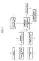
- FIG. 7is a block diagram of the behavior detection apparatus for estimating the stride and detecting a position.
- FIG. 6is a table for estimating the stride.
- the estimation of a traveling speed (moving distance) of the walker on the levelis disclosed in Japanese laid-open patent application publication No 2004-085511 and Journal of paper A by the Institute of Electronics, Information and Communication Engineers, Vol. J87-A, No. 1, pp 78-86, January 2004.
- a traveling speed (moving speed) of the walker on the levelis estimated as follows:
- An acceleration variation waveform in the vertical directionis frequency-analyzed in order to extract a frequency indicating the pace and detect the spectrum intensity.
- StridePace Spectrum Intensity ⁇ Coefficient for Each Walking Behavior
- the strideis estimated with a stride estimating unit 70 shown in FIG. 7 designed in consideration of the vertical movement.
- the stride estimation unit 70is supplied with a frequency and the spectrum intensity of the pace spectrum obtained by the behavior recognizing unit 2 and a behavior recognition result 7 as input data.
- FIG. 6will be described a process in the stride estimation unit 70 .
- the tableshows various types of stride estimation. Estimation for the level movement 63 and the staircase movement 64 is made in accordance with the moving speed 62 .
- the level movement 63is divided into the walking 60 and the running 61 detected by a single acceleration sensor.
- stride estimation calculations 65 and 66 for the level movementare made.
- the moving speedis obtained by a calculation 67 of a fixed stride ⁇ a pace, independently of the behavior of walking.
- a value of the fixed stridemay be assumed to be about 30 cm which is a size of a standard step. Further, to increase an accuracy, sizes of the steps of the staircases are recorded in geographical information, and used for the size of the step where the walker passes (will be mentioned later a unit for judging which one of staircases the walker passes).
- the traveling direction of the walkeris detected by the traveling direction detecting unit 71 .
- a traveling locus calculating unit 72obtains a moving locus by integration of the traveling speed and the traveling direction to provide a moving locus output 73 .
- an accurate stride estimationis provided though the walking behavior is associated with the vertical movement caused by the staircase or the like, so that the moving locus can be estimated from the stride.
- stride estimationmay be made as follows:
- the stride of walking on the levelis estimated, and when the walker behavior is recognized as walking accompanied by the vertical movement, the stride detected on the level is compensated on the basis of the walker behavior recognized result 7 (vertical movement) to obtain a moving speed and a traveling distance of the walker.
- FIG. 8is an illustration for operation during the movement on the staircase.
- FIG. 10is a block diagram of the third embodiment.
- Numeral 101 in FIG. 10is a behavior recognizing unit, which is the same as that shown in FIG. 1 , for recognizing the walking behavior with the vertical movement.
- Numeral 102denotes a position detecting unit of the walker. For example, this may be the moving locus calculating unit 72 described with reference to FIG. 7 , a position detecting unit using a GPS unit, or a wireless LAN.
- the position detection apparatus described in the third embodimentis provided to detect the position of the walker having a higher accuracy than the position information detected by the position detecting unit 102 .
- Numeral 103denotes a geographical information database for storing geographical information such as a position of a building, information of an internal structure and a position of a staircase, an elevator and the like, and information of outside roads and geographical information.
- Numeral 104denotes a geographical information searching unit using the walking behavior. The geographical information searching unit 104 searches the geographical database 103 for a position on the geographical information corresponding to the walking behavior detected by the behavior recognizing unit 102 with rough position information detected by the position detecting unit 101 .
- the geographical information corresponding to the walking behaviormeans that “staircase geographical information” is for staircase walking; “elevator geographical information for an elevator movement” is for elevator movement; “escalator geographical information” is for an escalator movement; and the like.
- the walkeris estimated to be at a place on a staircase, and the position information of the staircase can be obtained with reference to the geographical information of staircases.
- the geographical information searching unit 104searches the geographical information database 103 for the geographical information corresponding to the nearest staircase on the basis of the rough position information of the walker detected by the position detecting unit 102 .
- a change point and traveling direction detecting unit 108performs a process of a change point in the geographical information and a traveling direction using a change in the behavior of the walker to improve the detection accuracy and detect the traveling direction. With reference to FIGS. 8 and 10 will be described the process.
- Numeral 80denotes a staircase. It is assumed that the geographical information searching unit 104 judges that the walker is on the staircase 80 . As shown by an arrow 87 , the staircase 80 is so arranged that an ascending direction is north, and a descending direction is south. In a case that the walker moves from a section (staircase) to a section 82 (level), the result of behavior recognition of the walker is “ascending on the staircase” at the section 81 , and “level walking” at the section 82 . Thus, a point 85 where the recognition result of the behavior changes to “level walking” is an end of the ascending the staircase 80 .
- the change point and traveling direction detecting unit 108Since a shape and position data of the staircase 80 are stored in the geographic information database 103 , the point 85 is obtained on the basis of the information. Thus the change point and traveling direction detecting unit 108 generates a position output 105 and a traveling direction output 106 . As mentioned above, referring the change point of the walking behavior provides the position information having a higher accuracy than the result searched by the geographic information searching unit 104 . Further, because the ascending direction of the staircase 80 is north, the walker walks northward. Thus, the traveling direction of the walker can be detected. This is applicable to a case of descending the staircase 80 .
- the change point and traveling direction detecting unit 108recognizes a section 83 as “descending the staircase”, and a section 84 as “level walking”, and thus, the change point 86 is judged to be an end of the staircase 80 in descending.
- the traveling directionis judged to be the south because the walker descends the staircase 80 .
- the place at the walkercan be estimated by comparing the recognition result of the walking behavior with the geographical information, so that the current position and the traveling direction of the walker can be detected.
- FIGS. 11 , 12 , and 13a fourth embodiment in which position compensation is used in a position detection apparatus (an autonomous position detection apparatus or an inertial navigation method) for detecting a position by integrating the speed and the traveling direction per unit interval using the position detection apparatus in the third embodiment for detecting the position and the traveling direction with the walker behavior detection apparatus.
- FIG. 11shows a flowchart according to the fourth embodiment
- FIG. 12is an illustration of an example of a moving locus without compensation according to the second embodiment for comparison in the fourth embodiment
- FIG. 13is an illustration for showing a result of the operation according to the fourth embodiment in the case of the same movement of the walker as that shown in FIG. 12 .
- FIG. 12shows an example of the moving locus obtained by the position detection apparatus shown in FIG. 7 .
- Numeral 125denotes a starting point.
- Numerals 120 and 121denote staircases.
- An actual route in the example in FIG. 12is that the walker starts at the starting point 125 , ascends the staircase 120 across three floors, and moves on the three-floor-above floor toward the staircase 121 , and descends the staircase 121 across three floors to return to the starting point 125 .
- Numeral 124denotes the moving locus detected by the position detection apparatus shown in FIG. 7 . This shows an accurate moving locus from the starting point 125 to the staircase 120 .
- the moving locus 124does not reach the position of the staircase 121 though the walker reaches a region 123 circled by a dotted line where the walker is supposed to be the staircase 121 because errors are accumulated in the direction due to drift of the direction detection sensor such as a gyro during ascending the staircase 120 .
- an initial position of the walkeris set in a step 110 in FIG. 11 . This may be done by entering positional coordinate values and a traveling direction after the walker confirms the position thereof with a map, an absolute position and a traveling direction, as input data, detected by a unit capable of detecting an absolute position such as the GPS unit if the walker is at an area where the unit can be used, or positional information detected by reading ID information after a tag and the like for transmitting ID information corresponding to the position is provided using an RFID and the like.
- a process of estimating the position and the traveling directionis made using the detected walking behavior and the geographical information in a step 111 .
- This processcan be done with, for example, the apparatus shown in FIG. 10 .
- a judgmentis made whether estimation regarding the position and the traveling direction is possible, and (2) when the judgment is possible, the position and the traveling direction are calculated. If the estimation regarding the position and the traveling direction is possible, after the judging step 112 , the current position and the traveling direction are set again using the estimated position and traveling direction in a step 113 .
- the case that the estimation regarding the position and the direction are possiblecorresponds to the case that the corresponding place can be estimated through recognition between ascending and descending. For example, in the example in FIGS. 12 and 13 , when the walker passes the staircases 120 and 121 , this status can be detected and thus, the position of the staircase and the traveling direction are set again.
- a walking speed per unit time intervalis obtained and a traveling direction per the unit time interval (for example, the position detection apparatus shown in FIG. 7 ) are obtained in a step 114 .
- the moving locusis calculated by time-integration in a step 115 and a current position and a current traveling direction are outputted in a step 116 .
- the processes in the step 114 and 115are executed to output the current position and the current traveling direction in the step 116 without executing the setting process in the step 113 .
- processingreturns to the step 111 to repeat these processes to continuously output the position and the traveling direction.
- FIG. 13shows a result of this operation according to the fourth embodiment in the case of the same movement of the walker as that shown in FIG. 12 .
- the moving locus starting from the start point 132is compensated so as to be identical with the position and an extending direction of the staircase 120 , wherein cut portions halfway in the moving locus indicate places where the compensation is made.
- the moving locusis compensated so as to be identical with the position and an extending direction of the staircase 121 .
- the moving locusreaches the end 133 . This is substantially the same position of the start point 132 .
- this resultshows that an accuracy in the position detection is made higher than that regarding the end point 126 .
- the position compensation by the GPS unitis used for the initial position setting in the step 110 .
- a judgmentmay be made whether an accuracy of the GPS unit is reliable and if the accuracy is reliable, in addition to the position compensation by the behavior detection, the compensation can be made with values from the GPS unit. Further, when both the position compensation by the behavior detection and the position detection by the GPS unit are judged to be possible, one of the position compensation by the behavior detection and the position detection by the GPS unit which has a higher accuracy is selected.
- this apparatuscan be used as a compensating unit for the autonomous position detection apparatus in which an error is accumulated as time passes.
- an inertial navigation system 74 including an acceleration sensoris added which compensates the position information and the traveling direction information from the inertial navigation system on the basis of the detected position and traveling direction.
- numeral 144denotes an acceleration sensor
- numeral 142denotes a barometric sensor
- numeral 147denotes a direction sensor (a magnetic azimuth sensor or a gyro sensor).
- Numeral 143denotes a GPS unit.
- Numeral 146denotes a geographical information database
- numeral 141denotes a CPU as a processor
- numeral 145denotes a display.
- the acceleration sensor 144corresponds to the behavior variation signal detecting unit 1 and the sensor 10 shown in FIG. 1
- the barometric pressure sensor 142corresponds to the altitude detecting unit 3 in FIG. 1
- the CPU 141executes, on the basis of information from the acceleration sensor 144 and the barometric pressure sensor 142 , the behavior detection of the walker described with reference to FIG. 1 , the moving locus detection of the walker using an added direction sensor 147 described with reference to FIG. 7 , and the position and direction detection using the behavior of the walker described using FIG. 10 .
- the position information obtained by the GPS unit 143is used as the position of the walker navigation terminal without modification, or a value just before the receiving status becomes poor is used as setting information for the initial position in the step 110 in FIG. 11 .
- Numeral 146denotes a geographical information database which is used for searching, from the detection result of the walking behavior, corresponding geographical information such as a position of a staircase and stores data for drawing the moving locus obtained by the moving locus detecting apparatus described with reference to FIG. 11 and geographic information of the circumference such as buildings and roads.
- a result obtained by the database 146 and the CPU 141is drawn on a display unit 145 .
- drawn informationare the detection result of the walking behavior obtained with reference to FIG. 1 , the burned calorie of the walker, the current moving locus of the walker, and the geographical information displayed over the moving locus obtained with reference to FIGS. 7 , 10 , and 11 . This enables the walker to recognize where the walker is currently located by watching the display screen image 145 .
- the method of detecting a current position of the walker and the moving locusis described.
- Route guidance on the basis of route search information which is generally performed in car navigation unitsmay be performed on the basis of these pieces of information. Differences between the car navigation unit and the embodiment are as follows:
- the detectionis the same as a car navigator.
- the stride estimationis used though the car navigator detects a traveling distance using a vehicle speed pulse.
- the detected positionis compensated with the geographical information of, for example, staircases, elevators, and escalators, corresponding to the walking behavior, though the car navigator compensates the detected position along roads (map-matching).
- the walker navigatoris provided.
- FIG. 15a modification is shown in which a display terminal 151 is separated from a waist terminal 152 .
- a difference from the walker navigation terminal shown in FIG. 14is in that the display 151 is separated and the process is the same as that described with reference to FIG. 14 .
- the acceleration sensor 144 and the direction sensor 147are located at the waist of the walker which is the weight center of the walker.
- the walkermust watch the display screen to know the current place by detaching the walker navigation terminal 140 from the waist. This may cause an erroneous recognition or a position detection error in the detection result by the watching the display screen. Accordingly, in the example of FIG.
- the walker navigation terminalis divided into a waist terminal 152 , with a sensor part, attachable to the waist and an easy-to-watch display terminal 153 carried by a hand of the walker for providing a display screen on which image is displayed through transmitting and receiving information of screen image information and the like through communication line 150 .
- the communication line 150may be a wired one or a wireless one.
- This structureallows the walker navigation terminal to be divided into a display part of the easy-to-watch display terminal 153 and a sensor part of the waist terminal 152 , in which the error recognition of the walking behavior and the position detection error are suppressed. More specifically, dividing the navigation terminal is made in order to locate the sensors for detecting walking behavior detection of the walker at the most appropriate place.
- the CPU 141 and the geographical information database 146are arranged in the waist terminal 152 .
- the acceleration sensor 144 and the direction sensor 147may be arranged in the waist terminal 152 attachable to the waist and other sensors and processing circuits may be arranged in the display terminal 153 for providing the screen image to the walker.
- the sensors which may influence the detection accuracy of the walking behavior and the detection accuracy of the moving locuscan be separately located at the place with a good condition.
- the systemincludes a worker terminal 160 attachable to a worker and a worker observing terminal 167 remote from the worker.
- the worker terminal 160is provided with a communication unit 161 in addition to the structure described with reference to FIG. 14 .
- the worker terminal 160has a processing function described with reference to FIG. 14 to perform the detection of a behavior and a position of the worker and the detection of moving locus. These pieces of information can be watched by the worker with a display unit 145 similarly to the description made with reference to FIG. 14 and transmitted to the worker observing terminal 167 remotely located.
- Numeral 162denotes a communication line such as a wireless communication.
- Numeral 163denotes a communication unit
- numeral 164denotes a geographical information database
- Numeral 165is a CPU as a processor
- numeral 166is a display unit.
- the information, detected by the worker terminal 160 , transmitted through the communication line 162is received by the communication unit 163 to transmit it to a CPU 165 as a processor.
- the CPU 165processes a drawing process of the transmitted information. For example, if a walker behavior detection result of the worker is transmitted, the result of the walker behaviors (“walking”, “running”, and “ascending” and the like) is converted into display image data to be transmitted to the display 166 for drawing.
- the worker observing terminal 167provides detection of a behavior and a position of a worker at a remote place.
- FIG. 16only one worker terminal is shown.
- a plurality of worker observing terminalsmay be wirelessly connected to the worker observing terminal 167 to display behavior information and position information of a plurality of workers.
- the worker terminal 160is a terminal in which the screen image and the sensors are integrated.
- the worker terminal 160may be divided into a sensor part and the display part as described with reference to FIG. 15 .
- the position and the behavior of the workercan be detected at a remote place.
- a combination of the walking behavior recognizing apparatus with assumption that it is used on the level and recognition by the barometric pressure variationprovides recognition of the walker behavior accompanied by the vertical movement, and detection of burned calorie in accordance with the walking behavior.
- the stridecan be estimated accurately though the walking behavior is accompanied by the vertical movement on, for example, the staircase.
- the moving locuscan be estimated from the estimation of the stride.
- the present inventionprovides the estimation of the place where the walker is by comparing the recognition result of the walking behavior with the geographical information, which provides a current position and the traveling direction of the walker.
- the present inventionis applicable to the compensating unit for the autonomous position detection apparatus to be used to compensating the position detected by the autonomous position detection apparatus in which an error is accumulated as time passes.
- the present inventionis applied to the walker navigator which is usable to observe the position and the behavior of the worker at a remote place.
- the present inventionprovides the walker behavior detecting apparatus capable of accurately recognizing the walking status though the walker in a walking status in which the walker moves vertically.
Landscapes
- Engineering & Computer Science (AREA)
- Physics & Mathematics (AREA)
- General Physics & Mathematics (AREA)
- Remote Sensing (AREA)
- Radar, Positioning & Navigation (AREA)
- Theoretical Computer Science (AREA)
- Human Computer Interaction (AREA)
- General Health & Medical Sciences (AREA)
- Computer Vision & Pattern Recognition (AREA)
- Multimedia (AREA)
- Psychiatry (AREA)
- Social Psychology (AREA)
- Health & Medical Sciences (AREA)
- Navigation (AREA)
- Measurement Of Distances Traversed OnThe Ground (AREA)
- Instructional Devices (AREA)
- Measurement Of The Respiration, Hearing Ability, Form, And Blood Characteristics Of Living Organisms (AREA)
- Traffic Control Systems (AREA)
Abstract
Description
| TABLE 1 | ||||
| WALKING | WALKING | WALKING ON | ||
| TYPE | REST | ON LEVEL | ON SLOPE | STAIRCASE |
| KCAL/MIN | C1 | C2 | C3 | C4 |
Stride=Pace Spectrum Intensity×Coefficient for Each Walking Behavior
Traveling Speed=Stride×Pace
Traveling Distance=Time-Integration of Traveling Speed
Claims (14)
Applications Claiming Priority (2)
| Application Number | Priority Date | Filing Date | Title |
|---|---|---|---|
| JP2005-284426 | 2005-09-29 | ||
| JP2005284426AJP2007093433A (en) | 2005-09-29 | 2005-09-29 | Detector for motion of pedestrian |
Publications (2)
| Publication Number | Publication Date |
|---|---|
| US20070072158A1 US20070072158A1 (en) | 2007-03-29 |
| US7811203B2true US7811203B2 (en) | 2010-10-12 |
Family
ID=37499727
Family Applications (1)
| Application Number | Title | Priority Date | Filing Date |
|---|---|---|---|
| US11/528,329Expired - Fee RelatedUS7811203B2 (en) | 2005-09-29 | 2006-09-28 | Walker behavior detection apparatus |
Country Status (3)
| Country | Link |
|---|---|
| US (1) | US7811203B2 (en) |
| EP (1) | EP1770370B1 (en) |
| JP (1) | JP2007093433A (en) |
Cited By (33)
| Publication number | Priority date | Publication date | Assignee | Title |
|---|---|---|---|---|
| US20090018797A1 (en)* | 2007-07-13 | 2009-01-15 | Fujitsu Limited | Measuring method, measuring apparatus and computer readable information recording medium |
| US20100295665A1 (en)* | 2009-05-22 | 2010-11-25 | The Stanley Works Israel Ltd. | Object management system and method |
| US20110039522A1 (en)* | 2009-08-13 | 2011-02-17 | Palo Alto Research Center Incorporated | Venue inference using data sensed by mobile devices |
| US8108144B2 (en) | 2007-06-28 | 2012-01-31 | Apple Inc. | Location based tracking |
| US8175802B2 (en) | 2007-06-28 | 2012-05-08 | Apple Inc. | Adaptive route guidance based on preferences |
| US8180379B2 (en) | 2007-06-28 | 2012-05-15 | Apple Inc. | Synchronizing mobile and vehicle devices |
| US8204684B2 (en)* | 2007-06-28 | 2012-06-19 | Apple Inc. | Adaptive mobile device navigation |
| US8260320B2 (en) | 2008-11-13 | 2012-09-04 | Apple Inc. | Location specific content |
| US8275352B2 (en) | 2007-06-28 | 2012-09-25 | Apple Inc. | Location-based emergency information |
| US8290513B2 (en) | 2007-06-28 | 2012-10-16 | Apple Inc. | Location-based services |
| US8311526B2 (en) | 2007-06-28 | 2012-11-13 | Apple Inc. | Location-based categorical information services |
| US20120303271A1 (en)* | 2011-05-25 | 2012-11-29 | Sirf Technology Holdings, Inc. | Hierarchical Context Detection Method to Determine Location of a Mobile Device on a Person's Body |
| US8332402B2 (en) | 2007-06-28 | 2012-12-11 | Apple Inc. | Location based media items |
| US8355862B2 (en) | 2008-01-06 | 2013-01-15 | Apple Inc. | Graphical user interface for presenting location information |
| US8359643B2 (en) | 2008-09-18 | 2013-01-22 | Apple Inc. | Group formation using anonymous broadcast information |
| US8369867B2 (en) | 2008-06-30 | 2013-02-05 | Apple Inc. | Location sharing |
| CN103069469A (en)* | 2011-06-24 | 2013-04-24 | 索尼公司 | Altitude estimation apparatus, altitude estimation method, and program |
| US20130137549A1 (en)* | 2011-06-06 | 2013-05-30 | System Instruments Co., Ltd. | Training apparatus |
| US8644843B2 (en) | 2008-05-16 | 2014-02-04 | Apple Inc. | Location determination |
| US20140046223A1 (en)* | 2008-08-29 | 2014-02-13 | Philippe Kahn | Sensor fusion for activity identification |
| US8660530B2 (en) | 2009-05-01 | 2014-02-25 | Apple Inc. | Remotely receiving and communicating commands to a mobile device for execution by the mobile device |
| US8666367B2 (en) | 2009-05-01 | 2014-03-04 | Apple Inc. | Remotely locating and commanding a mobile device |
| US8670748B2 (en) | 2009-05-01 | 2014-03-11 | Apple Inc. | Remotely locating and commanding a mobile device |
| US8762056B2 (en) | 2007-06-28 | 2014-06-24 | Apple Inc. | Route reference |
| US20140188431A1 (en)* | 2012-11-01 | 2014-07-03 | Hti Ip, Llc | Method and system for determining whether steps have occurred |
| US8774825B2 (en) | 2007-06-28 | 2014-07-08 | Apple Inc. | Integration of map services with user applications in a mobile device |
| US9066199B2 (en) | 2007-06-28 | 2015-06-23 | Apple Inc. | Location-aware mobile device |
| US9109904B2 (en) | 2007-06-28 | 2015-08-18 | Apple Inc. | Integration of map services and user applications in a mobile device |
| US9250092B2 (en) | 2008-05-12 | 2016-02-02 | Apple Inc. | Map service with network-based query for search |
| US9374659B1 (en) | 2011-09-13 | 2016-06-21 | Dp Technologies, Inc. | Method and apparatus to utilize location data to enhance safety |
| US20170169704A1 (en)* | 2015-12-09 | 2017-06-15 | Robert Bosch Gmbh | Method and device for triggering pedestrian protection means and/or pedestrian warning means |
| US9702709B2 (en) | 2007-06-28 | 2017-07-11 | Apple Inc. | Disfavored route progressions or locations |
| US11047693B1 (en)* | 2015-09-11 | 2021-06-29 | Philip Raymond Schaefer | System and method for sensing walked position |
Families Citing this family (80)
| Publication number | Priority date | Publication date | Assignee | Title |
|---|---|---|---|---|
| JP4500184B2 (en)* | 2005-02-28 | 2010-07-14 | Npo法人熟年体育大学リサーチセンター | Endurance calculation device, endurance calculation method and program |
| JP2008027429A (en)* | 2006-06-19 | 2008-02-07 | Adc Technology Kk | Motion detector, position relation detector, physical activity load detector, and portable monitor |
| US8949070B1 (en) | 2007-02-08 | 2015-02-03 | Dp Technologies, Inc. | Human activity monitoring device with activity identification |
| US7753861B1 (en) | 2007-04-04 | 2010-07-13 | Dp Technologies, Inc. | Chest strap having human activity monitoring device |
| FR2918745B1 (en)* | 2007-07-12 | 2009-09-18 | Commissariat Energie Atomique | DEVICE FOR ASSISTING THE NAVIGATION OF A PERSON |
| US8555282B1 (en) | 2007-07-27 | 2013-10-08 | Dp Technologies, Inc. | Optimizing preemptive operating system with motion sensing |
| US7647196B2 (en)* | 2007-08-08 | 2010-01-12 | Dp Technologies, Inc. | Human activity monitoring device with distance calculation |
| DE102007043490A1 (en)* | 2007-09-12 | 2009-03-19 | Robert Bosch Gmbh | Method and device for detecting a distance |
| JP2009077825A (en)* | 2007-09-25 | 2009-04-16 | Panasonic Electric Works Co Ltd | Oscillating motion device |
| JP5202933B2 (en)* | 2007-11-30 | 2013-06-05 | 株式会社タニタ | Body motion detection device |
| JP2009192506A (en)* | 2008-02-18 | 2009-08-27 | Seiko Instruments Inc | Walk simulation apparatus |
| CN106139548A (en)* | 2008-02-27 | 2016-11-23 | 耐克创新有限合伙公司 | Movable information system and method |
| JP2009204568A (en)* | 2008-02-29 | 2009-09-10 | Seiko Instruments Inc | Walk simulation apparatus |
| JP5050934B2 (en)* | 2008-03-05 | 2012-10-17 | 住友電気工業株式会社 | LOCATION DEVICE, COMPUTER PROGRAM, AND LOCATION METHOD |
| JP2009229205A (en)* | 2008-03-21 | 2009-10-08 | Sumitomo Electric Ind Ltd | Pedestrian guidance system, computer program and pedestrian guiding method |
| JP2009229204A (en)* | 2008-03-21 | 2009-10-08 | Sumitomo Electric Ind Ltd | Location specifying system, computer program and location specifying method |
| JP5093492B2 (en)* | 2008-05-28 | 2012-12-12 | カシオ計算機株式会社 | Position detection apparatus and position detection program |
| US8996332B2 (en) | 2008-06-24 | 2015-03-31 | Dp Technologies, Inc. | Program setting adjustments based on activity identification |
| US8872646B2 (en) | 2008-10-08 | 2014-10-28 | Dp Technologies, Inc. | Method and system for waking up a device due to motion |
| JP5421571B2 (en)* | 2008-11-05 | 2014-02-19 | 国立大学法人弘前大学 | Walking characteristic evaluation system and locus generation method |
| US8150624B2 (en) | 2008-11-11 | 2012-04-03 | Northrop Grumman Systems Corporation | System and method for tracking a moving person |
| KR20100087551A (en)* | 2009-01-28 | 2010-08-05 | 한국과학기술연구원 | Apparatus for calculating calorie balance by classfying user's activity |
| JP5499500B2 (en)* | 2009-03-17 | 2014-05-21 | セイコーエプソン株式会社 | Stride estimation method |
| US20100250134A1 (en)* | 2009-03-24 | 2010-09-30 | Qualcomm Incorporated | Dead reckoning elevation component adjustment |
| JP5544508B2 (en)* | 2009-03-27 | 2014-07-09 | 株式会社国際電気通信基礎技術研究所 | Action identification system |
| JP5559305B2 (en)* | 2009-04-20 | 2014-07-23 | オーチス エレベータ カンパニー | Automatic adjustment of parameters for safety devices |
| US8792903B2 (en) | 2009-06-30 | 2014-07-29 | Qualcomm Incorporated | Trajectory-based location determination |
| DE102009028069A1 (en)* | 2009-07-29 | 2011-02-10 | Robert Bosch Gmbh | Pedometer with automatic step length adjustment, method for operating a pedometer and use of the pedometer |
| US8500604B2 (en)* | 2009-10-17 | 2013-08-06 | Robert Bosch Gmbh | Wearable system for monitoring strength training |
| JP5105492B2 (en)* | 2009-12-03 | 2012-12-26 | 独立行政法人産業技術総合研究所 | Mobile altitude measuring device |
| JP5471490B2 (en)* | 2010-01-20 | 2014-04-16 | オムロンヘルスケア株式会社 | Body motion detection device |
| DE102010031350A1 (en)* | 2010-07-14 | 2012-01-19 | Bayerische Motoren Werke Aktiengesellschaft | Method for determining position of person in e.g. pedestrian navigation, involves determining value of motion based on determined motion class, and using value of motion parameter for determining estimated actual position of person |
| JP5713595B2 (en)* | 2010-07-16 | 2015-05-07 | オムロンヘルスケア株式会社 | Motion detection device and control method of motion detection device |
| GB201017288D0 (en)* | 2010-10-13 | 2010-11-24 | Univ Nottingham | Positioning system |
| IL208684A (en)* | 2010-10-13 | 2017-01-31 | Elbit Systems Ltd | Pedestrian navigation system employing multiple data sources |
| JP5749056B2 (en)* | 2011-03-31 | 2015-07-15 | 株式会社ゼンリンデータコム | Navigation device |
| JP5748525B2 (en)* | 2011-03-31 | 2015-07-15 | 株式会社ゼンリンデータコム | Navigation device |
| JP5688326B2 (en)* | 2011-05-13 | 2015-03-25 | Kddi株式会社 | Portable device, program, and method for estimating up / down movement state using barometric sensor |
| JP5892785B2 (en)* | 2011-12-22 | 2016-03-23 | 株式会社日立製作所 | Information processing apparatus and information processing method |
| JP5892784B2 (en)* | 2011-12-22 | 2016-03-23 | 株式会社日立製作所 | Information processing apparatus and information processing method |
| JP6061063B2 (en)* | 2012-03-23 | 2017-01-18 | セイコーエプソン株式会社 | Advanced measuring device, navigation system, program, and recording medium |
| US10215587B2 (en)* | 2012-05-18 | 2019-02-26 | Trx Systems, Inc. | Method for step detection and gait direction estimation |
| JP6236862B2 (en)* | 2012-05-18 | 2017-11-29 | 花王株式会社 | How to calculate geriatric disorder risk |
| KR101250215B1 (en) | 2012-05-31 | 2013-04-03 | 삼성탈레스 주식회사 | Pedestrian dead-reckoning system using kalman filter and walking state estimation algorithm and method for height estimation thereof |
| JP5826120B2 (en)* | 2012-06-11 | 2015-12-02 | 日本電信電話株式会社 | Gait measuring device, method and program |
| JP5881541B2 (en)* | 2012-06-13 | 2016-03-09 | 株式会社日立製作所 | Information processing system and information processing method |
| JP6003284B2 (en)* | 2012-06-22 | 2016-10-05 | セイコーエプソン株式会社 | Portable equipment |
| WO2014097348A1 (en)* | 2012-12-18 | 2014-06-26 | 富士通株式会社 | Method for controlling information processing device, control program, and information processing device |
| KR102197911B1 (en)* | 2013-01-08 | 2021-01-04 | 삼성전자주식회사 | Method for determining user exercies information and apparatus for the same |
| US11006690B2 (en) | 2013-02-01 | 2021-05-18 | Nike, Inc. | System and method for analyzing athletic activity |
| US10926133B2 (en) | 2013-02-01 | 2021-02-23 | Nike, Inc. | System and method for analyzing athletic activity |
| JP6041386B2 (en)* | 2013-03-04 | 2016-12-07 | セイコーインスツル株式会社 | Electronics |
| US10113869B2 (en) | 2013-05-31 | 2018-10-30 | Asahi Kasei Kabushiki Kaisha | Device for identifying change in vertical direction by using air pressure measurement value |
| JP6229830B2 (en)* | 2013-09-11 | 2017-11-15 | カシオ計算機株式会社 | Exercise support device, exercise support method, and exercise support program |
| WO2015170703A1 (en)* | 2014-05-09 | 2015-11-12 | アルプス電気株式会社 | Movement detection program, object movement detection device and method therefor |
| CN107076554B (en)* | 2014-10-01 | 2019-08-20 | 英特尔公司 | Method and system for the determining and automatic jump detection of normal trajectories |
| JPWO2016098457A1 (en)* | 2014-12-17 | 2017-09-28 | ソニー株式会社 | Information processing apparatus, information processing method, and program |
| KR101642286B1 (en)* | 2015-02-12 | 2016-07-25 | 한국항공우주연구원 | Heading Orientation Estimation Method Using Pedestrian Characteristics in Indoor Environment |
| JP6569233B2 (en)* | 2015-02-16 | 2019-09-04 | 沖電気工業株式会社 | Posture estimation apparatus, posture estimation system, posture estimation method, and program |
| US10405781B2 (en) | 2015-07-28 | 2019-09-10 | Kyocera Corporation | Mobile device, movement state detection method, and non-transitory storage medium storing movement state detection program |
| JP2017034642A (en)* | 2015-07-28 | 2017-02-09 | 京セラ株式会社 | Mobile device, moving state detection method, and moving state detection program |
| JP6185031B2 (en) | 2015-09-28 | 2017-08-23 | 京セラ株式会社 | Portable device, control method and control program |
| JP6566046B2 (en)* | 2015-12-18 | 2019-08-28 | 株式会社リコー | Information processing system, information processing apparatus, information processing method, program, and recording medium |
| WO2018137016A1 (en)* | 2016-01-25 | 2018-08-02 | B-Temia Inc. | Gait profiler system and method |
| JP6494552B2 (en)* | 2016-03-29 | 2019-04-03 | Kddi株式会社 | Position estimating apparatus, program and method capable of correcting position based on transition between floors |
| JP2018009961A (en)* | 2016-06-30 | 2018-01-18 | セイコーインスツル株式会社 | Electronic apparatus, display system, electronic watch, and program |
| JP6802003B2 (en)* | 2016-08-18 | 2020-12-16 | 株式会社ゼンリンデータコム | Information processing equipment, information processing methods and programs |
| JP2018028485A (en)* | 2016-08-18 | 2018-02-22 | 株式会社ゼンリンデータコム | Information processing apparatus, information processing method, and program |
| JP6779707B2 (en)* | 2016-08-24 | 2020-11-04 | 京セラ株式会社 | Electronics, control methods, and control programs |
| JP6297663B1 (en)* | 2016-12-13 | 2018-03-20 | 京セラ株式会社 | Electronic device, correction control method, and correction control program |
| FR3060760B1 (en)* | 2016-12-21 | 2020-01-03 | Institut National Polytechnique De Toulouse | METHOD OF AUTONOMOUS GEOLOCATION OF A PERSON MOVING ON FOOT OR BY MEANS OF A NON-MOTORIZED MACHINE AND ASSOCIATED DEVICE |
| KR20180081187A (en)* | 2016-12-28 | 2018-07-16 | 주식회사 스탠딩에그 | Method and apparatus for tracking a gait |
| JP7015115B2 (en)* | 2017-03-30 | 2022-02-02 | セコム株式会社 | Shooting abnormality monitoring system and program |
| JP6391768B2 (en)* | 2017-06-12 | 2018-09-19 | 京セラ株式会社 | Portable device, control method and control program |
| JP7327397B2 (en)* | 2018-06-26 | 2023-08-16 | コニカミノルタ株式会社 | Computer-implemented programs, information processing systems, and computer-implemented methods |
| EP3586742B1 (en)* | 2018-06-27 | 2021-08-04 | The Swatch Group Research and Development Ltd | Methods for computing a real-time step length and speed of a running or walking individual |
| JP7172733B2 (en)* | 2019-02-28 | 2022-11-16 | トヨタ自動車株式会社 | Human Posture Estimation Device |
| KR20220126555A (en)* | 2021-03-09 | 2022-09-16 | 삼성전자주식회사 | Electronic device and method for determining user's step length using motion sensor and gps module of electronic device |
| CN113934212A (en)* | 2021-10-14 | 2022-01-14 | 北京科创安铨科技有限公司 | Intelligent building site safety inspection robot capable of being positioned |
| CN113908514A (en)* | 2021-11-25 | 2022-01-11 | 郑州升达经贸管理学院 | A storage device suitable for multiple types of sports equipment |
Citations (41)
| Publication number | Priority date | Publication date | Assignee | Title |
|---|---|---|---|---|
| JPH08261755A (en) | 1995-03-20 | 1996-10-11 | Cat I:Kk | Altitude measuring device |
| JPH08285582A (en) | 1995-04-11 | 1996-11-01 | Yupiteru Ind Co Ltd | Altimeter and altitude correcting method using the same |
| JPH10113343A (en) | 1996-07-03 | 1998-05-06 | Hitachi Ltd | Method and apparatus and system for recognizing actions and actions |
| JPH10148539A (en) | 1996-11-18 | 1998-06-02 | Toyota Motor Corp | Route guidance device |
| US5976083A (en)* | 1997-07-30 | 1999-11-02 | Living Systems, Inc. | Portable aerobic fitness monitor for walking and running |
| JPH11325929A (en) | 1998-05-21 | 1999-11-26 | Xanavi Informatics Corp | Present position calculating equipment |
| JPH11347021A (en) | 1998-06-05 | 1999-12-21 | Tokico Ltd | Consumed calorie calculating device |
| US6013007A (en)* | 1998-03-26 | 2000-01-11 | Liquid Spark, Llc | Athlete's GPS-based performance monitor |
| JP2000097722A (en) | 1998-09-26 | 2000-04-07 | Jatco Corp | Portable position detector and position managing system |
| US6148262A (en)* | 1996-11-01 | 2000-11-14 | Fry; William R. | Sports computer with GPS receiver and performance tracking capabilities |
| JP2001289632A (en) | 2000-01-31 | 2001-10-19 | Seiko Instruments Inc | Portable altimeter and altitude operating method |
| US20010048364A1 (en)* | 2000-02-23 | 2001-12-06 | Kalthoff Robert Michael | Remote-to-remote position locating system |
| JP2002031536A (en) | 2000-07-17 | 2002-01-31 | Xanavi Informatics Corp | Forward direction detection apparatus and method using gps position information and storage medium |
| JP2002048589A (en) | 2000-08-03 | 2002-02-15 | Tohoku Denshi Sangyo Kk | Moving path estimation device for moving objects |
| JP2002139340A (en) | 2000-10-30 | 2002-05-17 | Atr Media Integration & Communications Res Lab | Walking navigation device and navigation system using the same |
| JP2002217811A (en) | 2001-01-15 | 2002-08-02 | Hitachi Ltd | State detection method, state detection device, mobile terminal device, and movement state observation system |
| JP2002318122A (en) | 2001-04-23 | 2002-10-31 | Pioneer Electronic Corp | Device and method for measuring azimuth |
| US6522266B1 (en)* | 2000-05-17 | 2003-02-18 | Honeywell, Inc. | Navigation system, method and software for foot travel |
| US6605038B1 (en)* | 2000-06-16 | 2003-08-12 | Bodymedia, Inc. | System for monitoring health, wellness and fitness |
| US20040046692A1 (en)* | 2002-09-05 | 2004-03-11 | Robson Jack D. | Physical training system |
| JP2004085511A (en) | 2002-08-29 | 2004-03-18 | Hitachi Ltd | Method and system for estimating moving speed and position of moving object and navigation system |
| US20040064286A1 (en) | 2002-07-31 | 2004-04-01 | Levi Robert W. | Navigation device for personnel on foot |
| JP2004138513A (en) | 2002-10-18 | 2004-05-13 | Hitachi Ltd | Indoor position detecting device and indoor position detecting method |
| US6837827B1 (en)* | 2003-06-17 | 2005-01-04 | Garmin Ltd. | Personal training device using GPS data |
| WO2005004719A1 (en) | 2003-07-09 | 2005-01-20 | Newtest Oy | Method and apparatus for detecting types of exercise |
| US20050033200A1 (en)* | 2003-08-05 | 2005-02-10 | Soehren Wayne A. | Human motion identification and measurement system and method |
| US20050033515A1 (en)* | 2003-08-07 | 2005-02-10 | Motorola, Inc. | Wireless personal tracking and navigation system |
| US20050068169A1 (en)* | 2002-05-14 | 2005-03-31 | Copley Shuan Michael | Personal tracking device |
| JP2005091184A (en) | 2003-09-18 | 2005-04-07 | Clarion Co Ltd | Navigation system for vehicle |
| US6882955B1 (en) | 1997-10-02 | 2005-04-19 | Fitsense Technology, Inc. | Monitoring activity of a user in locomotion on foot |
| US20050137793A1 (en)* | 2001-12-21 | 2005-06-23 | Garmin Ltd., A Cayman Islands Corporation | Navigation system, method and device with detour algorithm |
| US20050197237A1 (en)* | 2004-03-03 | 2005-09-08 | Yu-Yu Chen | Integrated exercise detection device employing satellite positioning signal and exercise signal |
| US20050209061A1 (en)* | 2003-02-28 | 2005-09-22 | Nautilus, Inc. | Control system and method for an exercise apparatus |
| JP2005257644A (en) | 2004-03-15 | 2005-09-22 | Intelligent Cosmos Research Institute | Device, method, and program for detecting position |
| US6976083B1 (en)* | 1999-02-19 | 2005-12-13 | International Business Machines Corporation | Apparatus for providing direct data processing access using a queued direct input-output device |
| US20060098772A1 (en)* | 2002-10-28 | 2006-05-11 | Clothing Plus Oy | Distance meter |
| US20070021269A1 (en)* | 2005-07-25 | 2007-01-25 | Nike, Inc. | Interfaces and systems for displaying athletic performance information on electronic devices |
| US20070173378A1 (en)* | 2004-02-12 | 2007-07-26 | Ari Jamsen | Method for calibration of step length and arrangement utilizing the method |
| US7278966B2 (en)* | 2004-01-31 | 2007-10-09 | Nokia Corporation | System, method and computer program product for managing physiological information relating to a terminal user |
| US20070243855A1 (en)* | 1997-01-21 | 2007-10-18 | Hoffman Resources Llc | Personal security and tracking system |
| US7305303B2 (en)* | 2004-03-02 | 2007-12-04 | Honeywell International Inc. | Personal navigation using terrain-correlation and/or signal-of-opportunity information |
- 2005
- 2005-09-29JPJP2005284426Apatent/JP2007093433A/enactivePending
- 2006
- 2006-09-28USUS11/528,329patent/US7811203B2/ennot_activeExpired - Fee Related
- 2006-09-29EPEP06255079Apatent/EP1770370B1/ennot_activeExpired - Fee Related
Patent Citations (44)
| Publication number | Priority date | Publication date | Assignee | Title |
|---|---|---|---|---|
| JPH08261755A (en) | 1995-03-20 | 1996-10-11 | Cat I:Kk | Altitude measuring device |
| JPH08285582A (en) | 1995-04-11 | 1996-11-01 | Yupiteru Ind Co Ltd | Altimeter and altitude correcting method using the same |
| JPH10113343A (en) | 1996-07-03 | 1998-05-06 | Hitachi Ltd | Method and apparatus and system for recognizing actions and actions |
| US6148262A (en)* | 1996-11-01 | 2000-11-14 | Fry; William R. | Sports computer with GPS receiver and performance tracking capabilities |
| JPH10148539A (en) | 1996-11-18 | 1998-06-02 | Toyota Motor Corp | Route guidance device |
| US20070243855A1 (en)* | 1997-01-21 | 2007-10-18 | Hoffman Resources Llc | Personal security and tracking system |
| US6135951A (en)* | 1997-07-30 | 2000-10-24 | Living Systems, Inc. | Portable aerobic fitness monitor for walking and running |
| US5976083A (en)* | 1997-07-30 | 1999-11-02 | Living Systems, Inc. | Portable aerobic fitness monitor for walking and running |
| US6882955B1 (en) | 1997-10-02 | 2005-04-19 | Fitsense Technology, Inc. | Monitoring activity of a user in locomotion on foot |
| US6013007A (en)* | 1998-03-26 | 2000-01-11 | Liquid Spark, Llc | Athlete's GPS-based performance monitor |
| JPH11325929A (en) | 1998-05-21 | 1999-11-26 | Xanavi Informatics Corp | Present position calculating equipment |
| JPH11347021A (en) | 1998-06-05 | 1999-12-21 | Tokico Ltd | Consumed calorie calculating device |
| JP2000097722A (en) | 1998-09-26 | 2000-04-07 | Jatco Corp | Portable position detector and position managing system |
| US6976083B1 (en)* | 1999-02-19 | 2005-12-13 | International Business Machines Corporation | Apparatus for providing direct data processing access using a queued direct input-output device |
| JP2001289632A (en) | 2000-01-31 | 2001-10-19 | Seiko Instruments Inc | Portable altimeter and altitude operating method |
| US20010048364A1 (en)* | 2000-02-23 | 2001-12-06 | Kalthoff Robert Michael | Remote-to-remote position locating system |
| US6522266B1 (en)* | 2000-05-17 | 2003-02-18 | Honeywell, Inc. | Navigation system, method and software for foot travel |
| US6605038B1 (en)* | 2000-06-16 | 2003-08-12 | Bodymedia, Inc. | System for monitoring health, wellness and fitness |
| JP2002031536A (en) | 2000-07-17 | 2002-01-31 | Xanavi Informatics Corp | Forward direction detection apparatus and method using gps position information and storage medium |
| JP2002048589A (en) | 2000-08-03 | 2002-02-15 | Tohoku Denshi Sangyo Kk | Moving path estimation device for moving objects |
| JP2002139340A (en) | 2000-10-30 | 2002-05-17 | Atr Media Integration & Communications Res Lab | Walking navigation device and navigation system using the same |
| JP2002217811A (en) | 2001-01-15 | 2002-08-02 | Hitachi Ltd | State detection method, state detection device, mobile terminal device, and movement state observation system |
| JP2002318122A (en) | 2001-04-23 | 2002-10-31 | Pioneer Electronic Corp | Device and method for measuring azimuth |
| US20050137793A1 (en)* | 2001-12-21 | 2005-06-23 | Garmin Ltd., A Cayman Islands Corporation | Navigation system, method and device with detour algorithm |
| US20050068169A1 (en)* | 2002-05-14 | 2005-03-31 | Copley Shuan Michael | Personal tracking device |
| US20040064286A1 (en) | 2002-07-31 | 2004-04-01 | Levi Robert W. | Navigation device for personnel on foot |
| JP2004085511A (en) | 2002-08-29 | 2004-03-18 | Hitachi Ltd | Method and system for estimating moving speed and position of moving object and navigation system |
| US20040046692A1 (en)* | 2002-09-05 | 2004-03-11 | Robson Jack D. | Physical training system |
| JP2004138513A (en) | 2002-10-18 | 2004-05-13 | Hitachi Ltd | Indoor position detecting device and indoor position detecting method |
| US20060098772A1 (en)* | 2002-10-28 | 2006-05-11 | Clothing Plus Oy | Distance meter |
| US20050209061A1 (en)* | 2003-02-28 | 2005-09-22 | Nautilus, Inc. | Control system and method for an exercise apparatus |
| US20050288154A1 (en)* | 2003-06-17 | 2005-12-29 | Garmin Ltd., A Cayman Islands Corporation | Personal training device using GPS data |
| US6837827B1 (en)* | 2003-06-17 | 2005-01-04 | Garmin Ltd. | Personal training device using GPS data |
| US20050107216A1 (en)* | 2003-06-17 | 2005-05-19 | Garmin Ltd., A Cayman Islands Corporation | Personal training device using GPS data |
| WO2005004719A1 (en) | 2003-07-09 | 2005-01-20 | Newtest Oy | Method and apparatus for detecting types of exercise |
| US20050033200A1 (en)* | 2003-08-05 | 2005-02-10 | Soehren Wayne A. | Human motion identification and measurement system and method |
| US20050033515A1 (en)* | 2003-08-07 | 2005-02-10 | Motorola, Inc. | Wireless personal tracking and navigation system |
| JP2005091184A (en) | 2003-09-18 | 2005-04-07 | Clarion Co Ltd | Navigation system for vehicle |
| US7278966B2 (en)* | 2004-01-31 | 2007-10-09 | Nokia Corporation | System, method and computer program product for managing physiological information relating to a terminal user |
| US20070173378A1 (en)* | 2004-02-12 | 2007-07-26 | Ari Jamsen | Method for calibration of step length and arrangement utilizing the method |
| US7305303B2 (en)* | 2004-03-02 | 2007-12-04 | Honeywell International Inc. | Personal navigation using terrain-correlation and/or signal-of-opportunity information |
| US20050197237A1 (en)* | 2004-03-03 | 2005-09-08 | Yu-Yu Chen | Integrated exercise detection device employing satellite positioning signal and exercise signal |
| JP2005257644A (en) | 2004-03-15 | 2005-09-22 | Intelligent Cosmos Research Institute | Device, method, and program for detecting position |
| US20070021269A1 (en)* | 2005-07-25 | 2007-01-25 | Nike, Inc. | Interfaces and systems for displaying athletic performance information on electronic devices |
Non-Patent Citations (3)
| Title |
|---|
| Japanese office action mailed May 11, 2010 with English translation. |
| Journal of paper A by The Institute of Electronics, Information and Communication Engineers, vol. J87-A, No. 1, pp. 78-86, Jan. 2004. |
| Partial European Search Report dated Jan. 11, 2007 (four (4) pages). |
Cited By (69)
| Publication number | Priority date | Publication date | Assignee | Title |
|---|---|---|---|---|
| US8548735B2 (en) | 2007-06-28 | 2013-10-01 | Apple Inc. | Location based tracking |
| US8332402B2 (en) | 2007-06-28 | 2012-12-11 | Apple Inc. | Location based media items |
| US12114284B2 (en) | 2007-06-28 | 2024-10-08 | Apple Inc. | Location-aware mobile device |
| US11665665B2 (en) | 2007-06-28 | 2023-05-30 | Apple Inc. | Location-aware mobile device |
| US8108144B2 (en) | 2007-06-28 | 2012-01-31 | Apple Inc. | Location based tracking |
| US8175802B2 (en) | 2007-06-28 | 2012-05-08 | Apple Inc. | Adaptive route guidance based on preferences |
| US8180379B2 (en) | 2007-06-28 | 2012-05-15 | Apple Inc. | Synchronizing mobile and vehicle devices |
| US8204684B2 (en)* | 2007-06-28 | 2012-06-19 | Apple Inc. | Adaptive mobile device navigation |
| US11419092B2 (en) | 2007-06-28 | 2022-08-16 | Apple Inc. | Location-aware mobile device |
| US8275352B2 (en) | 2007-06-28 | 2012-09-25 | Apple Inc. | Location-based emergency information |
| US20120253665A1 (en)* | 2007-06-28 | 2012-10-04 | Apple Inc. | Adaptive Mobile Device Navigation |
| US8290513B2 (en) | 2007-06-28 | 2012-10-16 | Apple Inc. | Location-based services |
| US8311526B2 (en) | 2007-06-28 | 2012-11-13 | Apple Inc. | Location-based categorical information services |
| US11221221B2 (en) | 2007-06-28 | 2022-01-11 | Apple Inc. | Location based tracking |
| US10508921B2 (en) | 2007-06-28 | 2019-12-17 | Apple Inc. | Location based tracking |
| US9131342B2 (en) | 2007-06-28 | 2015-09-08 | Apple Inc. | Location-based categorical information services |
| US10952180B2 (en) | 2007-06-28 | 2021-03-16 | Apple Inc. | Location-aware mobile device |
| US9109904B2 (en) | 2007-06-28 | 2015-08-18 | Apple Inc. | Integration of map services and user applications in a mobile device |
| US12228411B2 (en) | 2007-06-28 | 2025-02-18 | Apple Inc. | Location based tracking |
| US9066199B2 (en) | 2007-06-28 | 2015-06-23 | Apple Inc. | Location-aware mobile device |
| US9891055B2 (en) | 2007-06-28 | 2018-02-13 | Apple Inc. | Location based tracking |
| US9310206B2 (en) | 2007-06-28 | 2016-04-12 | Apple Inc. | Location based tracking |
| US10412703B2 (en) | 2007-06-28 | 2019-09-10 | Apple Inc. | Location-aware mobile device |
| US9414198B2 (en) | 2007-06-28 | 2016-08-09 | Apple Inc. | Location-aware mobile device |
| US10064158B2 (en) | 2007-06-28 | 2018-08-28 | Apple Inc. | Location aware mobile device |
| US8924144B2 (en) | 2007-06-28 | 2014-12-30 | Apple Inc. | Location based tracking |
| US8694026B2 (en) | 2007-06-28 | 2014-04-08 | Apple Inc. | Location based services |
| US8738039B2 (en) | 2007-06-28 | 2014-05-27 | Apple Inc. | Location-based categorical information services |
| US9702709B2 (en) | 2007-06-28 | 2017-07-11 | Apple Inc. | Disfavored route progressions or locations |
| US8762056B2 (en) | 2007-06-28 | 2014-06-24 | Apple Inc. | Route reference |
| US9578621B2 (en) | 2007-06-28 | 2017-02-21 | Apple Inc. | Location aware mobile device |
| US8774825B2 (en) | 2007-06-28 | 2014-07-08 | Apple Inc. | Integration of map services with user applications in a mobile device |
| US20090018797A1 (en)* | 2007-07-13 | 2009-01-15 | Fujitsu Limited | Measuring method, measuring apparatus and computer readable information recording medium |
| US8355862B2 (en) | 2008-01-06 | 2013-01-15 | Apple Inc. | Graphical user interface for presenting location information |
| US9702721B2 (en) | 2008-05-12 | 2017-07-11 | Apple Inc. | Map service with network-based query for search |
| US9250092B2 (en) | 2008-05-12 | 2016-02-02 | Apple Inc. | Map service with network-based query for search |
| US8644843B2 (en) | 2008-05-16 | 2014-02-04 | Apple Inc. | Location determination |
| US10368199B2 (en) | 2008-06-30 | 2019-07-30 | Apple Inc. | Location sharing |
| US10841739B2 (en) | 2008-06-30 | 2020-11-17 | Apple Inc. | Location sharing |
| US8369867B2 (en) | 2008-06-30 | 2013-02-05 | Apple Inc. | Location sharing |
| US8784309B2 (en)* | 2008-08-29 | 2014-07-22 | Dp Technologies, Inc. | Sensor fusion for activity identification |
| US20140046223A1 (en)* | 2008-08-29 | 2014-02-13 | Philippe Kahn | Sensor fusion for activity identification |
| US9144398B1 (en) | 2008-08-29 | 2015-09-29 | Dp Technologies, Inc. | Sensor fusion for activity identification |
| US8359643B2 (en) | 2008-09-18 | 2013-01-22 | Apple Inc. | Group formation using anonymous broadcast information |
| US8260320B2 (en) | 2008-11-13 | 2012-09-04 | Apple Inc. | Location specific content |
| US12250262B2 (en) | 2009-05-01 | 2025-03-11 | Apple Inc. | Remotely locating and commanding a mobile device |
| US8666367B2 (en) | 2009-05-01 | 2014-03-04 | Apple Inc. | Remotely locating and commanding a mobile device |
| US8660530B2 (en) | 2009-05-01 | 2014-02-25 | Apple Inc. | Remotely receiving and communicating commands to a mobile device for execution by the mobile device |
| US9979776B2 (en) | 2009-05-01 | 2018-05-22 | Apple Inc. | Remotely locating and commanding a mobile device |
| US8670748B2 (en) | 2009-05-01 | 2014-03-11 | Apple Inc. | Remotely locating and commanding a mobile device |
| US8928463B2 (en)* | 2009-05-22 | 2015-01-06 | The Stanley Works Israel Ltd. | Object management system and method |
| US9639722B2 (en) | 2009-05-22 | 2017-05-02 | The Stanley Works Israel Ltd. | Object management system and method |
| US20100295665A1 (en)* | 2009-05-22 | 2010-11-25 | The Stanley Works Israel Ltd. | Object management system and method |
| US8078152B2 (en)* | 2009-08-13 | 2011-12-13 | Palo Alto Research Center Incorporated | Venue inference using data sensed by mobile devices |
| US20110039522A1 (en)* | 2009-08-13 | 2011-02-17 | Palo Alto Research Center Incorporated | Venue inference using data sensed by mobile devices |
| US20120303271A1 (en)* | 2011-05-25 | 2012-11-29 | Sirf Technology Holdings, Inc. | Hierarchical Context Detection Method to Determine Location of a Mobile Device on a Person's Body |
| US10145707B2 (en)* | 2011-05-25 | 2018-12-04 | CSR Technology Holdings Inc. | Hierarchical context detection method to determine location of a mobile device on a person's body |
| US8992384B2 (en)* | 2011-06-06 | 2015-03-31 | System Instruments Co., Ltd | Training apparatus |
| US20130137549A1 (en)* | 2011-06-06 | 2013-05-30 | System Instruments Co., Ltd. | Training apparatus |
| US8788232B2 (en)* | 2011-06-24 | 2014-07-22 | Sony Corporation | Altitude estimation apparatus, altitude estimation method, and program |
| CN103069469A (en)* | 2011-06-24 | 2013-04-24 | 索尼公司 | Altitude estimation apparatus, altitude estimation method, and program |
| EP2583267A4 (en)* | 2011-06-24 | 2014-06-11 | Sony Corp | ALTITUDE ESTIMATING APPARATUS, ALTITUDE ESTIMATING METHOD, AND PROGRAM |
| CN103069469B (en)* | 2011-06-24 | 2017-01-18 | 索尼公司 | Altitude estimation apparatus, altitude estimation method, and program |
| US9374659B1 (en) | 2011-09-13 | 2016-06-21 | Dp Technologies, Inc. | Method and apparatus to utilize location data to enhance safety |
| US20140188431A1 (en)* | 2012-11-01 | 2014-07-03 | Hti Ip, Llc | Method and system for determining whether steps have occurred |
| US10030993B2 (en)* | 2012-11-01 | 2018-07-24 | Verizon Connect Inc. | Method and system for determining whether steps have occurred |
| US11852493B1 (en)* | 2015-09-11 | 2023-12-26 | Vortant Technologies, Llc | System and method for sensing walked position |
| US11047693B1 (en)* | 2015-09-11 | 2021-06-29 | Philip Raymond Schaefer | System and method for sensing walked position |
| US20170169704A1 (en)* | 2015-12-09 | 2017-06-15 | Robert Bosch Gmbh | Method and device for triggering pedestrian protection means and/or pedestrian warning means |
Also Published As
| Publication number | Publication date |
|---|---|
| EP1770370A3 (en) | 2007-04-25 |
| EP1770370B1 (en) | 2010-08-18 |
| US20070072158A1 (en) | 2007-03-29 |
| EP1770370A2 (en) | 2007-04-04 |
| JP2007093433A (en) | 2007-04-12 |
Similar Documents
| Publication | Publication Date | Title |
|---|---|---|
| US7811203B2 (en) | Walker behavior detection apparatus | |
| US11237272B2 (en) | Method and computer processing apparatus for generating data relating to a vertical structure of a built environment and detecting a floor change | |
| US9008996B2 (en) | Moving body positioning device | |
| US9961508B1 (en) | Systems and methods for determining indoor location and floor of a mobile device | |
| US8355888B2 (en) | Pedestrian navigation system and method | |
| EP3908805B1 (en) | Method and system for tracking a mobile device | |
| CN108139456A (en) | The method of accelerometer assisting navigation | |
| JP5105492B2 (en) | Mobile altitude measuring device | |
| US9255943B2 (en) | Information processing apparatus and information processing method | |
| JP3775779B2 (en) | Walking navigation device and navigation system using the same | |
| JPWO2011068184A1 (en) | Mobile positioning device | |
| JP2007333998A (en) | Automatic map generator | |
| US12130968B2 (en) | Systems and methods for determining contexts of mobile devices | |
| CN106461401B (en) | Information processing apparatus, information processing method, and computer program | |
| Vanini et al. | Adaptive context-agnostic floor transition detection on smart mobile devices | |
| Gu et al. | Integration of positioning and activity context information for lifelog in urban city area | |
| KR102269074B1 (en) | Method and apparatus for determining positions in indoor | |
| JP2015224932A (en) | Information processing device, information processing method, and computer program | |
| JP6329915B2 (en) | Positioning system | |
| KR102223319B1 (en) | Method and system of gathering and using composite data for indoor location recognition through crowdsorcing | |
| EP0763712A1 (en) | Vehicle navigator system | |
| KR20240045536A (en) | Apparatus and method of providing vehicle position information | |
| CN112964243B (en) | Indoor positioning method and device | |
| Ai et al. | Floor identification with commercial smartphones in wifi-based indoor localization system | |
| Lin et al. | LocMe: Human locomotion and map exploitation based indoor localization |
Legal Events
| Date | Code | Title | Description |
|---|---|---|---|
| AS | Assignment | Owner name:HITACHI, LTD., JAPAN Free format text:ASSIGNMENT OF ASSIGNORS INTEREST;ASSIGNORS:UNUMA, MUNETOSHI;OTSU, FUMITAKA;SATOU, SHINOBU;AND OTHERS;SIGNING DATES FROM 20060920 TO 20060926;REEL/FRAME:018477/0628 Owner name:HITACHI, LTD., JAPAN Free format text:ASSIGNMENT OF ASSIGNORS INTEREST;ASSIGNORS:UNUMA, MUNETOSHI;OTSU, FUMITAKA;SATOU, SHINOBU;AND OTHERS;REEL/FRAME:018477/0628;SIGNING DATES FROM 20060920 TO 20060926 | |
| AS | Assignment | Owner name:HITACHI, LTD., JAPAN Free format text:ASSIGNMENT OF ASSIGNORS INTEREST;ASSIGNORS:UNUMA, MUNETOSHI;OTSU, FUMITAKA;SATOU, SHINOBU;AND OTHERS;SIGNING DATES FROM 20060920 TO 20060926;REEL/FRAME:019273/0776 Owner name:HITACHI ADVANCED SYSTEMS CORPORATION, JAPAN Free format text:ASSIGNMENT OF ASSIGNORS INTEREST;ASSIGNORS:UNUMA, MUNETOSHI;OTSU, FUMITAKA;SATOU, SHINOBU;AND OTHERS;SIGNING DATES FROM 20060920 TO 20060926;REEL/FRAME:019273/0776 Owner name:HITACHI, LTD., JAPAN Free format text:ASSIGNMENT OF ASSIGNORS INTEREST;ASSIGNORS:UNUMA, MUNETOSHI;OTSU, FUMITAKA;SATOU, SHINOBU;AND OTHERS;REEL/FRAME:019273/0776;SIGNING DATES FROM 20060920 TO 20060926 Owner name:HITACHI ADVANCED SYSTEMS CORPORATION, JAPAN Free format text:ASSIGNMENT OF ASSIGNORS INTEREST;ASSIGNORS:UNUMA, MUNETOSHI;OTSU, FUMITAKA;SATOU, SHINOBU;AND OTHERS;REEL/FRAME:019273/0776;SIGNING DATES FROM 20060920 TO 20060926 | |
| REMI | Maintenance fee reminder mailed | ||
| LAPS | Lapse for failure to pay maintenance fees | ||
| STCH | Information on status: patent discontinuation | Free format text:PATENT EXPIRED DUE TO NONPAYMENT OF MAINTENANCE FEES UNDER 37 CFR 1.362 | |
| FP | Lapsed due to failure to pay maintenance fee | Effective date:20141012 |