US7810787B2 - Animal watering valve having elastomeric diaphragm - Google Patents
Animal watering valve having elastomeric diaphragmDownload PDFInfo
- Publication number
- US7810787B2 US7810787B2US11/379,842US37984206AUS7810787B2US 7810787 B2US7810787 B2US 7810787B2US 37984206 AUS37984206 AUS 37984206AUS 7810787 B2US7810787 B2US 7810787B2
- Authority
- US
- United States
- Prior art keywords
- valve
- diaphragm
- valve stem
- animal watering
- seat
- Prior art date
- Legal status (The legal status is an assumption and is not a legal conclusion. Google has not performed a legal analysis and makes no representation as to the accuracy of the status listed.)
- Active, expires
Links
Images


Classifications
- A—HUMAN NECESSITIES
- A01—AGRICULTURE; FORESTRY; ANIMAL HUSBANDRY; HUNTING; TRAPPING; FISHING
- A01K—ANIMAL HUSBANDRY; AVICULTURE; APICULTURE; PISCICULTURE; FISHING; REARING OR BREEDING ANIMALS, NOT OTHERWISE PROVIDED FOR; NEW BREEDS OF ANIMALS
- A01K7/00—Watering equipment for stock or game
- A01K7/02—Automatic devices
- A01K7/06—Automatic devices actuated by the animal
- A—HUMAN NECESSITIES
- A01—AGRICULTURE; FORESTRY; ANIMAL HUSBANDRY; HUNTING; TRAPPING; FISHING
- A01K—ANIMAL HUSBANDRY; AVICULTURE; APICULTURE; PISCICULTURE; FISHING; REARING OR BREEDING ANIMALS, NOT OTHERWISE PROVIDED FOR; NEW BREEDS OF ANIMALS
- A01K39/00—Feeding or drinking appliances for poultry or other birds
- A01K39/02—Drinking appliances
- A01K39/0213—Nipple drinkers
Definitions
- the inventionrelates to animal watering valves and, more particularly, relates to animal actuated valves for use by mice, rats, and other relatively small laboratory animals or commercially raised animals.
- the valve element disclosed in the Edstrom patentincludes a head on the valve stem which is resiliently biased against a valve seat by an elastomeric diaphragm.
- the valve seattakes the form of an elastomeric ring against which a downstream surface of the valve stem head abuts.
- the diaphragmis formed from a unitary elastomeric element including a central web portion and a cylindrical peripheral portion. The web portion has apertures formed therethrough for the passage of fluid, and also has a recess counterbored into the downstream surface thereof for receiving a head of the valve stem. A downstream end of the outer peripheral portion is clamped in place within the housing, and an upstream, second end engages a shoulder on the valve cap.
- the diaphragm disclosed in the Edstrom patentworks very well but exhibits some disadvantages. For instance, flow tends to be inconsistent with the direction and/or extent of valve stem deflection because the gap between the head of the valve stem and the valve seat is relatively small—even when the valve stem is deflected its maximum amount. Flow consistency is also reduced by the fact that the outlet ports are located peripherally outboard of the valve stem head, leading to water flow from the ports into the downstream sections of the valve to take the form in distinct streams of unequal volume. In addition, because the entire upstream surface of the valve stem head rests on the diaphragm, the forces required to deflect the valve stem increase exponentially with stem deflection—which can be a hindrance to small or weak animals.
- the needhas additionally arisen to provide a diaphragm-type animal watering valve that is easier to operate than existing animal watering valves.
- an animal watering valvein accordance with a first aspect of the invention, includes a housing having an upstream inlet and a downstream outlet.
- the housingsupports a valve seat, an elastomeric diaphragm, and a valve stem.
- the elastomeric diaphragmis disposed in the bore upstream of the valve seat and includes a perforated portion having apertures formed therethrough that having outlets, and a seat portion having a valve stem head abutment surface.
- a valve stemis located in the bore and extends from the diaphragm toward the outlet.
- the valve stemhas a head that is clamped between the diaphragm and the valve seat and a tail that is laterally deflectable to move the valve stem head relative to the diaphragm from a seated position.
- the valve stem headUpon moving it to an unseated position, the valve stem head seals against the valve seat to prevent water flow though the valve to an unseated position in which the valve stem head pivots relative to the valve seat to permit water flows through the apertures of the diaphragm, between the valve stem head and the valve seat, and out of the valve, the valve stem head having an upstream surface that abuts the seat portion. At least portions of the flow aperture outlets in the diaphragm are located radially inwardly of and axially upstream of the upstream surface of the valve stem head.
- the diaphragmincludes a body through which the apertures extend and a radially central protrusion which extends axially downstream from a downstream surface of the body to the valve stem head abutment portion.
- the diaphragmincludes a perforated web portion having a downstream surface which presents the seat portion and which has apertures formed therethrough, and a cylindrical peripheral portion which extends axially downstream from the web portion and which clamped in place within the valve housing.
- An annular channelmay be formed in the perforated web portion of the diaphragm around an outer radial periphery of the seat portion and connects the outlets of said apertures to one another.
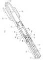
- FIG. 1is a partially cut away perspective view of an animal watering valve constructed in accordance with a first embodiment of the invention
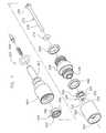
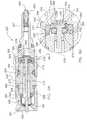
- FIG. 2is an exploded perspective view of the animal watering valve of FIG. 1 ;
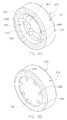
- FIGS. 3A and 3Bare downstream and upstream perspective views, respectively, of a diaphragm of the animal watering valve of FIGS. 1 and 2 ;
- FIG. 4Ais a sectional side elevation view of the animal watering valve of FIGS. 1 and 2 , illustrating the valve in its seated or closed position;
- FIG. 4Bis an enlarged fragmentary view of a portion of FIG. 4A ;
- FIGS. 5A and 5Bcorrespond to FIGS. 4A and 4B , respectively, and illustrate the animal watering valve in its unseated or open position;
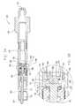
- FIG. 6is a partially cut-away perspective view of an animal watering valve constructed in accordance with a second preferred embodiment of the invention.
- FIG. 7is an exploded perspective view of the animal watering valve of FIG. 6 ;
- FIGS. 8A and 8Bare downstream and upstream perspective views, respectively, of a diaphragm of the animal watering valve of FIGS. 6 and 7 ;
- FIG. 9Ais a sectional side elevation view of the animal watering valve of FIGS. 6 and 7 , illustrating the valve in its seated or closed position;
- FIG. 9Bis an enlarged fragmentary view of a portion of FIG. 9A ;
- FIGS. 10A and 10Bcorrespond to FIGS. 9A and 9B , respectively, and illustrate the animal watering valve in its unseated or open position.
- the animal watering valve 20includes a housing 50 having formed therein an inlet 52 , an outlet 54 , and an elongated longitudinal bore 56 extending from the inlet 52 to the outlet 54 .
- the housing 50is preferably formed from three axially aligned pieces including a body 58 a valve cap 60 threaded onto an upstream end of the body 58 , and a valve guard 62 threaded onto a downstream end of the body 58 .
- O-rings 64 and 66seal the body 58 to the valve cap 60 and the valve guard 62 , respectively.
- a diaphragm 70 , valve stem 72 , and valve seat 74are clamped between the body 58 and the valve guard 62 .
- the valve stem 72forms a portion of a valve element for selectively sealing against a mating portion formed by the valve seat 74 and to provide an animal-accessible element for opening the valve.
- the valve stem 72includes (1) a head 76 which is clamped between the diaphragm 70 and the valve seat 74 and (2) an elongated tail 78 extending longitudinally through the bore 56 beyond the outlet 54 into a recessed end of the valve guard 62 .
- the headhas an upstream surface 80 and downstream surface 82 .
- the upstream surface 80 of the head 76could be domed or curved but is preferably flat.
- the valve seat 74preferably comprises an elastomeric ring mounted in a counterbore in the upstream end of the valve guard 62 .
- the ringhas an upstream surface that seals against the downstream surface 82 of the valve stem head when the valve stem head 76 is in the seated position shown in FIGS. 4A and 4B .
- the valve seat 74could be either O-shaped or D-shaped so long as it (1) provides a sealing surface for the head 76 of the valve stem 72 and (2) provides an engaging surface for the upstream end of the valve stem tail 78 for centering purposes.
- the diaphragm 70acts as a return member for the valve element formed by the valve stem head 76 and the valve seat 74 . It is designed to (1) impose controlled, uniform return forces on the valve stem 72 , (2) provide better control of fluid flow through the valve 20 , (3) help center the valve stem 72 in the valve 20 , and (4) help reduce the forces required to actuate the valve 20 .
- the diaphragm 70is formed from a unitary elastomeric element having an upstream body 84 and a downstream, radially centered, imperforate protrusion 86 .
- the bodyhas a diameter of 0.237 inches and a height of 0.08 inches.
- the protrusion 86has a diameter of 0.100 inches and a height of 0.045 inches. It terminates in a planar downstream abutment surface 88 against which the upstream end 80 of the valve stem head 76 rests.
- the downstream surface 90 of the body 84is planar from the outer surface of the protrusion 86 to the outer edge of the body 84 .
- the upstream surface 92 of the bodyrests against a shoulder on the valve cap 60 at its outer portion is counterbored in its central portion to form a recess 94 having a diameter that is at least as large as the diameter of the protrusion 86 .
- recess 94at least partially collapses upon valve actuation to permit the protrusion 86 to move away from the valve seat 74 to accommodate valve stem pivoting.
- a number of circumferentially spaced apertures 96are formed axially through the body 84 at the perimeter of the recess 94 and terminate in outlet ports 98 formed on the downstream surface 90 of the body 84 .
- Three equally spaced apertures 96are provided in the illustrated embodiment.
- the animal watering valve 20normally assumes the position illustrated in FIGS. 1-6 in which the valve stem 72 extends coaxially through the bore 56 with the head 76 being maintained in sealing contact with the seat 74 under the imposition of biasing forces supplied by the diaphragm 70 .
- Wateris supplied to the inlet 52 of the housing 50 but is prevented from flowing through the valve 20 by the sealing relationship between the head 76 of the valve stem 72 and the valve seat 74 .
- an animaldeflects the tail 78 of the valve stem 72 using its snout, thus pivoting the head 76 against the diaphragm 70 and forming a gap “G” between the underside of the head 76 and the valve seat 74 as illustrated in FIGS. 5A and 5B .
- Actuation forcesare reduced when compared to a valve employing a standard cup-type diaphragm because the reduced contact between the diaphragm 70 and the valve stem 72 results in less deflection of the diaphragm at full stroke.
- valve 20Upon release of the valve stem 72 , the valve 20 closes automatically under the return forces imposed by the diaphragm 70 .
- the inventive valvewhen compared to the previously known valves, requires reduced actuating forces, applies improved closing forces, provides improved flow rate control at given supply pressure and flow settings, and can be easily and simply adjusted to provide different flow rates at a given pressure setting without adversely affecting valve operation.
- an animal watering valve 220is illustrated which differs from the animal watering valve 20 of the first embodiment primarily in that it has a different diaphragm and has a shield 320 not found in the animal watering valve 20 of the first embodiment. It is also configured for direct mounting in a cage and connection to a hard water bottle or an animal watering system rather than for connection to an animal watering bag and, accordingly, has a slightly different housing. Elements of valve 220 corresponding to those of the valve 20 of the first embodiment are thus designated by the same reference numeral, incremented by 200.
- Valve 220includes a housing 250 which houses a diaphragm 270 , a valve stem 272 , and a seat 274 .
- the housing 250has formed therein an inlet 252 , an outlet 254 , and an elongated longitudinal bore 256 extending from the inlet 252 to the outlet 254 .
- the housing 250is formed from a valve body 258 , a valve cap 260 threaded onto an upstream end of the valve body 258 , and a valve guard 262 threaded onto a downstream end of the valve body.
- the valve body 258is sealed to the valve cap 260 and the valve guard 262 by O-rings 264 and 266 , respectively.
- the upstream end of the valve cap 260presents a shank 267 that is configured for mating with a docking mechanism (not shown) of an animal watering system.
- a spring loaded plug 268is mounted in the upstream end of the shank 267 for preventing debris from entering the bore 256 when the valve 220 is disconnected from the docking mechanism.
- the diaphragm 270 , valve stem 272 , and valve seat 274are clamped between the valve body 258 and the valve cap 260 .
- the valve seat 274comprises a ring retained in a counterbore on the upstream end of the valve body 258 .
- valve stem 272includes a flat head 276 and an elongated tail 278 extending downstream through the bore 256 from the head 276 .
- the head 276has a flat upstream abutment surface 280 and a downstream sealing surface 282 (see FIGS. 9B and 10B ).
- the diaphragm 270 of this embodimentis configured to improve flow consistency and reduce actuating forces. However, it is more similar to the diaphragm discussed above in connection with the Edstrom patent in that it has a cup in its downstream surface that receives the valve stem head 276 .
- the diaphragm 270is formed from a unitary elastomeric element, including a central web portion 300 and a cylindrical peripheral portion 302 .
- the peripheral portion 302has a cylindrical portion 304 extending downstream from the web portion 300 .
- the portion 304is clamped between a boss 306 on the valve body 258 and the inner periphery of the valve cap 260 to hold the diaphragm 270 in position without distorting the web portion 300 .
- the upstream end of the peripheral portion 302engages a shoulder 308 on the valve cap 260 .
- the peripheral portion 302thus provides a support via which the web portion can stretch 300 without undue distortion.
- the web portion 300has apertures 296 formed therethrough for the passage of fluid and also has a recess 310 counterbored into the downstream surface thereof to form the pocket for receiving the valve stem head 276 .
- a number (seven in the illustrated embodiment) of apertures 296are spaced equidistantly around the web portion as best seen in FIGS. 8A and 8B .
- the downstream surfaces of the apertures 296form outlet ports 298 that are located radially inwardly of and axially upstream of the upstream surface 280 of the valve stream head 276 as seen in FIGS. 9B and 10B .
- the outlet ports 298are in direct contact with the installed valve stem head, thereby improving flow consistency.
- the recess 310has an ID that is larger than the OD of the valve stem head 276 so that the head 276 does not engage the ID of the recess, at least in the seated position thereof.
- an upstream portion 312 of the ID of the recess 310is inclined inwardly from the downstream end towards the upstream end thereof. The angle reduces the contact force between the diaphragm 270 and the outer diameter of the valve stem head 276 , allowing the valve stem head 276 to move more freely.
- Flow consistencyis further improved through the provision of a channel 314 bounded at its OD by the ID of the upper end portion of the recess 310 .
- the channel 314links the outlet ports 298 together to better distribute fluid flow past the valve stem head 276 should fluid flow through the apertures be none uniform.
- the channel 314extends below the surface of the web portion 300 , forming a raised abutment surface 288 against which the upstream surface 280 of the valve stem head 276 rests.
- the channel 314also reduces the contact area between the diaphragm 270 and the valve stem head 276 , thereby reducing the actuation forces required to open the valve 220 . It also allows for reduction of the diaphragm displacement at full stem travel and reduces the leverage imposed on the stem by the diaphragm 270 without reducing the axial force.
- the diaphragm 270 of this embodimenthas a diameter of 0.362 inches with the web portion having a diameter of 0.264 inches and the channel having a diameter of 0.208 inches.
- the abutment surface 286has a diameter 0.135 inches—less than that of the valve stem head 276 .
- the purpose of the shield 320is to prevent bedding material or other debris from being lodged in the bore 256 between the valve stem tail 78 and the side of the bore 256 and thus to prevent the valve 220 from being stuck in its open position.
- the shield 320is formed from a unitary elastomeric cup-shaped member including a cylindrical body 322 , a ring 324 extending radially outwardly from an upstream end portion of the body 322 , and a membrane 326 covering a downstream end of the body 322 .
- the ring 324is retained in a shield retainer 328 extending axially from the downstream end of the valve body 258 .
- the membrane 326has a central aperture 330 formed therethrough which, the stem 272 passes. Unobstructed flow out of the valve 220 is also facilitated by an opening 332 formed in the cylindrical body 322 of the shield 320 .
- the animal watering valve 220normally assumes the position illustrated in FIGS. 1-6 in which the valve stem 272 extends coaxially through the bore 256 and through the center of the aperture 330 in the membrane 326 such that its head 272 is maintained in sealing contact with the valve seat 274 under the imposition of biasing forces supplied by the diaphragm 270 .
- Wateris supplied to the inlet 252 of the housing 250 but is prevented from flowing through the valve 220 by the sealing relationship between the head 276 of the valve stem 272 and the valve seat 274 .
- an animalinserts its snout into the frustoconical recess formed in the downstream end of the valve guard 262 and deflects the tail 278 of the valve stem 272 , thus pivoting the head 276 against the diaphragm 270 and forming a gap “G” between the downstream surface of the valve stream head 276 and the valve seat 274 as best illustrated in FIG. 10B .
- Wateris free to flow through the apertures 296 in the diaphragm 270 , through the gap “G”, through the bore 256 in the valve housing 250 , between the valve stem tail 278 and the now enlarged aperture 330 in the membrane 326 of the shield 320 (and also through the aperture 332 in the side of the body 322 and past the OD of the membrane 326 ), and out of the outlet 254 of the valve housing 250 . Because the outer diameter of the valve stem head 276 does not contact the diaphragm to the extent that it would with a diaphragm of the type disclosed in the Edstrom patent, valve actuation forces are reduced. Upon release of the valve stem 272 , the valve 220 closes automatically under the return forces imposed by the diaphragm 270 .
Landscapes
- Life Sciences & Earth Sciences (AREA)
- Environmental Sciences (AREA)
- Animal Husbandry (AREA)
- Biodiversity & Conservation Biology (AREA)
- Birds (AREA)
- Lift Valve (AREA)
- Catching Or Destruction (AREA)
- Multiple-Way Valves (AREA)
Abstract
Description
Claims (18)
Priority Applications (5)
| Application Number | Priority Date | Filing Date | Title |
|---|---|---|---|
| US11/379,842US7810787B2 (en) | 2006-04-24 | 2006-04-24 | Animal watering valve having elastomeric diaphragm |
| DE602007008866TDE602007008866D1 (en) | 2006-04-24 | 2007-04-09 | ANIMAL WET VALVE WITH ELASTOMER MEMBRANE |
| EP07760324AEP2009984B1 (en) | 2006-04-24 | 2007-04-09 | Animal watering valve having elastomeric diaphragm |
| AT07760324TATE479331T1 (en) | 2006-04-24 | 2007-04-09 | ANIMAL DRINKING VALVE WITH ELASTOMERIC MEMBRANE |
| PCT/US2007/066240WO2007127597A2 (en) | 2006-04-24 | 2007-04-09 | Animal watering valve having elastomeric diaphragm |
Applications Claiming Priority (1)
| Application Number | Priority Date | Filing Date | Title |
|---|---|---|---|
| US11/379,842US7810787B2 (en) | 2006-04-24 | 2006-04-24 | Animal watering valve having elastomeric diaphragm |
Publications (2)
| Publication Number | Publication Date |
|---|---|
| US20070245969A1 US20070245969A1 (en) | 2007-10-25 |
| US7810787B2true US7810787B2 (en) | 2010-10-12 |
Family
ID=38544002
Family Applications (1)
| Application Number | Title | Priority Date | Filing Date |
|---|---|---|---|
| US11/379,842Active2028-07-19US7810787B2 (en) | 2006-04-24 | 2006-04-24 | Animal watering valve having elastomeric diaphragm |
Country Status (5)
| Country | Link |
|---|---|
| US (1) | US7810787B2 (en) |
| EP (1) | EP2009984B1 (en) |
| AT (1) | ATE479331T1 (en) |
| DE (1) | DE602007008866D1 (en) |
| WO (1) | WO2007127597A2 (en) |
Cited By (11)
| Publication number | Priority date | Publication date | Assignee | Title |
|---|---|---|---|---|
| US20140000524A1 (en)* | 2012-06-27 | 2014-01-02 | Michael Allen Orgill | Breather cap assembly |
| USD708402S1 (en)* | 2012-06-27 | 2014-07-01 | Ctb, Inc. | Breather cap for use in connection with a watering assembly |
| WO2014145480A3 (en)* | 2013-03-15 | 2015-02-19 | Hydropac/Lab Products, Inc. | Fluid delivery valve system and method |
| US20150272080A1 (en)* | 2014-03-28 | 2015-10-01 | Ctb, Inc. | Sow lactation feeder with adjustable actuator |
| US9433190B2 (en) | 2013-03-13 | 2016-09-06 | Edstrom Industries, Llc | Animal watering valve |
| US9763425B2 (en) | 2001-10-19 | 2017-09-19 | Hydropac/Lab Products, Inc. | Method and system of providing sealed bags of fluid at the clean side of a laboratory facility |
| US10104867B2 (en) | 2013-03-15 | 2018-10-23 | Hydropac/Lab Products, Inc. | Automatic fluid Delivery systems and methods |
| US10178853B2 (en)* | 2015-07-02 | 2019-01-15 | Crystal Spring Colony Farms Ltd. | Water supply for animals |
| US10238086B2 (en) | 2013-03-15 | 2019-03-26 | Hydropac/Lab Products, Inc. | Automatic fluid delivery systems and methods |
| US10542731B2 (en) | 2012-06-27 | 2020-01-28 | Ctb, Inc. | Breather cap assembly |
| US11484009B2 (en) | 2019-07-02 | 2022-11-01 | Crystal Spring Colony Farms Ltd. | Water supply nipple for animals |
Families Citing this family (1)
| Publication number | Priority date | Publication date | Assignee | Title |
|---|---|---|---|---|
| US11603948B2 (en)* | 2018-06-18 | 2023-03-14 | Avidity Science, Llc | Animal watering valve |
Citations (23)
| Publication number | Priority date | Publication date | Assignee | Title |
|---|---|---|---|---|
| US2710594A (en) | 1953-02-24 | 1955-06-14 | Earl C Thompson | Poultry drinking valve |
| US2939424A (en) | 1957-04-09 | 1960-06-07 | Robert O Frederiksen | Demand delivery watering device for domestic house animals |
| US3256917A (en) | 1962-02-01 | 1966-06-21 | Baumann Kurt | Nonreturn valve with pressure release |
| US3513811A (en)* | 1967-12-22 | 1970-05-26 | Upjohn Co | Animal drinking valve with two-piece stem |
| US3550560A (en)* | 1969-05-07 | 1970-12-29 | William E Edstrom | Animal drinking devices |
| US3698685A (en) | 1971-03-08 | 1972-10-17 | Waters Mfg Co Inc | Animal actuated drinking valve |
| US4006716A (en) | 1975-12-01 | 1977-02-08 | Atco Manufacturing Co., Inc. | Miniature animal-watering valve |
| US4187804A (en) | 1976-07-21 | 1980-02-12 | Aratowerk Walter Von Taschitzki | Water dispenser for livestock |
| US4258666A (en) | 1979-03-12 | 1981-03-31 | Edstrom William E | Adjustable animal watering or drinking device |
| US4320891A (en) | 1980-04-21 | 1982-03-23 | Howard Ingram Cairns | Nipple operated animal watering valve |
| US4391225A (en) | 1982-02-18 | 1983-07-05 | Sparks Jacob D | Springless nipple waterer valve |
| US4403570A (en) | 1982-01-11 | 1983-09-13 | Cyclone International Incorporated | Animal waterer |
| US4406253A (en) | 1981-11-16 | 1983-09-27 | Atco Manufacturing Co. Inc. | Animal bite valve |
| US5065700A (en) | 1990-10-17 | 1991-11-19 | Se Lab Group, Inc. | Shutter for animal-watering valve |
| US5074250A (en) | 1990-03-02 | 1991-12-24 | Clark Iv Reuben B | Animal-operated watering device |
| US5329877A (en) | 1991-02-09 | 1994-07-19 | Lubing Maschinenfabrik Ludwig Benign Gmbh & Co. Kg | Watering valve for small animals having variable flow rates |
| US5373811A (en) | 1994-01-21 | 1994-12-20 | Wastell; Terry | Nipple waterer substitute compression element |
| US5501177A (en) | 1994-08-23 | 1996-03-26 | Edstrom Industries, Inc. | Animal watering valve |
| US5816194A (en) | 1997-08-25 | 1998-10-06 | Novalek, Inc. | Animal operated water dispensing valve |
| US6739283B1 (en) | 2003-04-16 | 2004-05-25 | Jun Hui Lin | Water dispenser for small animals or pets |
| US6912971B1 (en) | 2002-11-06 | 2005-07-05 | Aquaflow Laboratory Products Limited | Valve arrangement and assembly for dispensing a liquid from a container to an animal |
| US6941893B2 (en) | 2001-10-19 | 2005-09-13 | Lab Products, Inc. | Fluid delivery system |
| US6983721B2 (en) | 2001-10-19 | 2006-01-10 | Hydropac/Lab Products, Inc. | Method and system of providing sealed bags of fluid at the clean side of a laboratory facility |
- 2006
- 2006-04-24USUS11/379,842patent/US7810787B2/enactiveActive
- 2007
- 2007-04-09DEDE602007008866Tpatent/DE602007008866D1/enactiveActive
- 2007-04-09EPEP07760324Apatent/EP2009984B1/enactiveActive
- 2007-04-09WOPCT/US2007/066240patent/WO2007127597A2/enactiveApplication Filing
- 2007-04-09ATAT07760324Tpatent/ATE479331T1/ennot_activeIP Right Cessation
Patent Citations (23)
| Publication number | Priority date | Publication date | Assignee | Title |
|---|---|---|---|---|
| US2710594A (en) | 1953-02-24 | 1955-06-14 | Earl C Thompson | Poultry drinking valve |
| US2939424A (en) | 1957-04-09 | 1960-06-07 | Robert O Frederiksen | Demand delivery watering device for domestic house animals |
| US3256917A (en) | 1962-02-01 | 1966-06-21 | Baumann Kurt | Nonreturn valve with pressure release |
| US3513811A (en)* | 1967-12-22 | 1970-05-26 | Upjohn Co | Animal drinking valve with two-piece stem |
| US3550560A (en)* | 1969-05-07 | 1970-12-29 | William E Edstrom | Animal drinking devices |
| US3698685A (en) | 1971-03-08 | 1972-10-17 | Waters Mfg Co Inc | Animal actuated drinking valve |
| US4006716A (en) | 1975-12-01 | 1977-02-08 | Atco Manufacturing Co., Inc. | Miniature animal-watering valve |
| US4187804A (en) | 1976-07-21 | 1980-02-12 | Aratowerk Walter Von Taschitzki | Water dispenser for livestock |
| US4258666A (en) | 1979-03-12 | 1981-03-31 | Edstrom William E | Adjustable animal watering or drinking device |
| US4320891A (en) | 1980-04-21 | 1982-03-23 | Howard Ingram Cairns | Nipple operated animal watering valve |
| US4406253A (en) | 1981-11-16 | 1983-09-27 | Atco Manufacturing Co. Inc. | Animal bite valve |
| US4403570A (en) | 1982-01-11 | 1983-09-13 | Cyclone International Incorporated | Animal waterer |
| US4391225A (en) | 1982-02-18 | 1983-07-05 | Sparks Jacob D | Springless nipple waterer valve |
| US5074250A (en) | 1990-03-02 | 1991-12-24 | Clark Iv Reuben B | Animal-operated watering device |
| US5065700A (en) | 1990-10-17 | 1991-11-19 | Se Lab Group, Inc. | Shutter for animal-watering valve |
| US5329877A (en) | 1991-02-09 | 1994-07-19 | Lubing Maschinenfabrik Ludwig Benign Gmbh & Co. Kg | Watering valve for small animals having variable flow rates |
| US5373811A (en) | 1994-01-21 | 1994-12-20 | Wastell; Terry | Nipple waterer substitute compression element |
| US5501177A (en) | 1994-08-23 | 1996-03-26 | Edstrom Industries, Inc. | Animal watering valve |
| US5816194A (en) | 1997-08-25 | 1998-10-06 | Novalek, Inc. | Animal operated water dispensing valve |
| US6941893B2 (en) | 2001-10-19 | 2005-09-13 | Lab Products, Inc. | Fluid delivery system |
| US6983721B2 (en) | 2001-10-19 | 2006-01-10 | Hydropac/Lab Products, Inc. | Method and system of providing sealed bags of fluid at the clean side of a laboratory facility |
| US6912971B1 (en) | 2002-11-06 | 2005-07-05 | Aquaflow Laboratory Products Limited | Valve arrangement and assembly for dispensing a liquid from a container to an animal |
| US6739283B1 (en) | 2003-04-16 | 2004-05-25 | Jun Hui Lin | Water dispenser for small animals or pets |
Cited By (16)
| Publication number | Priority date | Publication date | Assignee | Title |
|---|---|---|---|---|
| US9763425B2 (en) | 2001-10-19 | 2017-09-19 | Hydropac/Lab Products, Inc. | Method and system of providing sealed bags of fluid at the clean side of a laboratory facility |
| US10271526B2 (en) | 2012-06-27 | 2019-04-30 | Ctb, Inc. | Breather cap assembly |
| US8904962B2 (en)* | 2012-06-27 | 2014-12-09 | Ctb, Inc. | Breather cap assembly |
| US10542731B2 (en) | 2012-06-27 | 2020-01-28 | Ctb, Inc. | Breather cap assembly |
| US20140000524A1 (en)* | 2012-06-27 | 2014-01-02 | Michael Allen Orgill | Breather cap assembly |
| USD708402S1 (en)* | 2012-06-27 | 2014-07-01 | Ctb, Inc. | Breather cap for use in connection with a watering assembly |
| US9433190B2 (en) | 2013-03-13 | 2016-09-06 | Edstrom Industries, Llc | Animal watering valve |
| US10238086B2 (en) | 2013-03-15 | 2019-03-26 | Hydropac/Lab Products, Inc. | Automatic fluid delivery systems and methods |
| US10104867B2 (en) | 2013-03-15 | 2018-10-23 | Hydropac/Lab Products, Inc. | Automatic fluid Delivery systems and methods |
| US9732882B2 (en) | 2013-03-15 | 2017-08-15 | Hydropac/Lab Products, Inc. | Fluid delivery valve system and method |
| WO2014145480A3 (en)* | 2013-03-15 | 2015-02-19 | Hydropac/Lab Products, Inc. | Fluid delivery valve system and method |
| US10932444B2 (en) | 2013-03-15 | 2021-03-02 | Hydropac/Lab Products, Inc. | Automatic fluid delivery systems and methods |
| US9247712B2 (en)* | 2014-03-28 | 2016-02-02 | Ctb, Inc. | Sow lactation feeder with adjustable actuator |
| US20150272080A1 (en)* | 2014-03-28 | 2015-10-01 | Ctb, Inc. | Sow lactation feeder with adjustable actuator |
| US10178853B2 (en)* | 2015-07-02 | 2019-01-15 | Crystal Spring Colony Farms Ltd. | Water supply for animals |
| US11484009B2 (en) | 2019-07-02 | 2022-11-01 | Crystal Spring Colony Farms Ltd. | Water supply nipple for animals |
Also Published As
| Publication number | Publication date |
|---|---|
| US20070245969A1 (en) | 2007-10-25 |
| EP2009984A2 (en) | 2009-01-07 |
| WO2007127597A2 (en) | 2007-11-08 |
| DE602007008866D1 (en) | 2010-10-14 |
| ATE479331T1 (en) | 2010-09-15 |
| WO2007127597A3 (en) | 2007-12-27 |
| EP2009984B1 (en) | 2010-09-01 |
Similar Documents
| Publication | Publication Date | Title |
|---|---|---|
| US7810787B2 (en) | Animal watering valve having elastomeric diaphragm | |
| US6003468A (en) | Animal watering valve with deflectable elastomeric boot | |
| US5456279A (en) | Diaphragm-type pilot valve having a self-cleaning control orifice | |
| US6929245B2 (en) | Stem to sleeve connection for pivot actuated sleeve valve | |
| US5779148A (en) | Pop-up sprinkler with pressure regulator | |
| US4927115A (en) | Valve for a hand held spray nozzle | |
| US5501177A (en) | Animal watering valve | |
| US9433190B2 (en) | Animal watering valve | |
| JPH11152779A (en) | Flush valve | |
| US3454032A (en) | Combination shutoff,antibackflow and vacuum relief valve | |
| JPS63501815A (en) | Backflow prevention device for fluid flow path | |
| US6079437A (en) | Diaphragm valve with flow control stem air bleed | |
| US20090139586A1 (en) | Flush Valve Diaphragm | |
| JPH02128633A (en) | Valve for water drinking of poultry | |
| US4320891A (en) | Nipple operated animal watering valve | |
| US3735772A (en) | Water valve apparatus | |
| US5104090A (en) | Irrigation valve | |
| US5505427A (en) | Flushometer handle seal | |
| US3907249A (en) | Valve device for restricting the flow of a liquid by a helical flow passage | |
| EP3806622B1 (en) | Animal watering valve | |
| US9816636B2 (en) | Rigid piston retrofit for a diaphragm flush valve | |
| US5373811A (en) | Nipple waterer substitute compression element | |
| US9605764B2 (en) | Liquid control valve | |
| JPS6396367A (en) | Digital valve | |
| US20130277581A1 (en) | Rigid Piston Retrofit for a Diaphragm Flush Valve |
Legal Events
| Date | Code | Title | Description |
|---|---|---|---|
| AS | Assignment | Owner name:EDSTROM INDUSTRIES, INC., WISCONSIN Free format text:ASSIGNMENT OF ASSIGNORS INTEREST;ASSIGNOR:JOHNSON, MR. PAUL S.;REEL/FRAME:017515/0359 Effective date:20060420 | |
| STCF | Information on status: patent grant | Free format text:PATENTED CASE | |
| FPAY | Fee payment | Year of fee payment:4 | |
| AS | Assignment | Owner name:JOHNSON BANK, WISCONSIN Free format text:SECURITY INTEREST;ASSIGNOR:EDSTROM, INC. (F/K/A EDSTROM INDUSTRIES, INC.);REEL/FRAME:033697/0807 Effective date:20140812 | |
| AS | Assignment | Owner name:EDSTROM, INC., WISCONSIN Free format text:CHANGE OF NAME;ASSIGNOR:EDSTROM INDUSTRIES, INC.;REEL/FRAME:037903/0951 Effective date:20121227 | |
| AS | Assignment | Owner name:JOHNSON BANK, WISCONSIN Free format text:SECURITY INTEREST;ASSIGNOR:EDSTROM INDUSTRIES, LLC;REEL/FRAME:037854/0107 Effective date:20160229 | |
| AS | Assignment | Owner name:EDSTROM INDUSTRIES, LLC, WISCONSIN Free format text:ASSIGNMENT OF ASSIGNORS INTEREST;ASSIGNOR:EDSTROM, INC.;REEL/FRAME:038089/0067 Effective date:20160229 | |
| MAFP | Maintenance fee payment | Free format text:PAYMENT OF MAINTENANCE FEE, 8TH YR, SMALL ENTITY (ORIGINAL EVENT CODE: M2552) Year of fee payment:8 | |
| AS | Assignment | Owner name:AVIDITY SCIENCE, LLC, WISCONSIN Free format text:CHANGE OF NAME;ASSIGNOR:EDSTROM INDUSTRIES, LLC;REEL/FRAME:047130/0844 Effective date:20180725 | |
| AS | Assignment | Owner name:AVIDITY SCIENCE, LLC (FORMERLY KNOWN AS EDSTROM INDUSTRIES, LLC), WISCONSIN Free format text:RELEASE BY SECURED PARTY;ASSIGNOR:JOHNSON BANK;REEL/FRAME:054168/0281 Effective date:20201022 | |
| AS | Assignment | Owner name:FIRST MIDWEST BANK, AS ADMINISTRATIVE AGENT, ILLINOIS Free format text:SECURITY INTEREST;ASSIGNORS:AVIDITY SCIENCE, LLC;LAB PRODUCTS, INC.;BIO MEDIC DATA SYSTEMS, INC.;AND OTHERS;REEL/FRAME:054212/0417 Effective date:20201026 | |
| MAFP | Maintenance fee payment | Free format text:PAYMENT OF MAINTENANCE FEE, 12TH YR, SMALL ENTITY (ORIGINAL EVENT CODE: M2553); ENTITY STATUS OF PATENT OWNER: SMALL ENTITY Year of fee payment:12 | |
| AS | Assignment | Owner name:HYDROPAC, LLC, WISCONSIN Free format text:RELEASE BY SECURED PARTY;ASSIGNOR:OLD NATIONAL BANK (AS SUCCESSOR-BY-MERGER TO FIRST MIDWEST BANK), AS ADMINISTRATIVE AGENT;REEL/FRAME:065604/0848 Effective date:20231117 Owner name:BIO MEDIC DATA SYSTEMS, LLC, DELAWARE Free format text:RELEASE BY SECURED PARTY;ASSIGNOR:OLD NATIONAL BANK (AS SUCCESSOR-BY-MERGER TO FIRST MIDWEST BANK), AS ADMINISTRATIVE AGENT;REEL/FRAME:065604/0848 Effective date:20231117 Owner name:AVIDITY SCIENCE, LLC, WISCONSIN Free format text:RELEASE BY SECURED PARTY;ASSIGNOR:OLD NATIONAL BANK (AS SUCCESSOR-BY-MERGER TO FIRST MIDWEST BANK), AS ADMINISTRATIVE AGENT;REEL/FRAME:065604/0848 Effective date:20231117 |