US7810584B2 - Method of directional drilling with steerable drilling motor - Google Patents
Method of directional drilling with steerable drilling motorDownload PDFInfo
- Publication number
- US7810584B2 US7810584B2US11/524,009US52400906AUS7810584B2US 7810584 B2US7810584 B2US 7810584B2US 52400906 AUS52400906 AUS 52400906AUS 7810584 B2US7810584 B2US 7810584B2
- Authority
- US
- United States
- Prior art keywords
- drilling
- drill string
- rotation rate
- tool face
- borehole
- Prior art date
- Legal status (The legal status is an assumption and is not a legal conclusion. Google has not performed a legal analysis and makes no representation as to the accuracy of the status listed.)
- Active, expires
Links
- 238000005553drillingMethods0.000titleclaimsabstractdescription185
- 238000000034methodMethods0.000titleclaimsdescription59
- 238000005259measurementMethods0.000description15
- 239000012530fluidSubstances0.000description10
- 230000015572biosynthetic processEffects0.000description8
- 230000008859changeEffects0.000description8
- 238000012937correctionMethods0.000description8
- 238000005755formation reactionMethods0.000description8
- 230000035515penetrationEffects0.000description8
- 230000008569processEffects0.000description8
- 230000007423decreaseEffects0.000description4
- 230000033001locomotionEffects0.000description4
- 230000003247decreasing effectEffects0.000description3
- 230000000977initiatory effectEffects0.000description3
- 230000009471actionEffects0.000description2
- 238000010586diagramMethods0.000description2
- 238000012986modificationMethods0.000description2
- 230000004048modificationEffects0.000description2
- 239000011435rockSubstances0.000description2
- 238000013459approachMethods0.000description1
- 238000005520cutting processMethods0.000description1
- 238000011161developmentMethods0.000description1
- 238000006073displacement reactionMethods0.000description1
- 238000011160researchMethods0.000description1
- 230000011664signalingEffects0.000description1
- 239000003381stabilizerSubstances0.000description1
- 230000036962time dependentEffects0.000description1
- 230000007704transitionEffects0.000description1
- 230000000007visual effectEffects0.000description1
Images


Classifications
- E—FIXED CONSTRUCTIONS
- E21—EARTH OR ROCK DRILLING; MINING
- E21B—EARTH OR ROCK DRILLING; OBTAINING OIL, GAS, WATER, SOLUBLE OR MELTABLE MATERIALS OR A SLURRY OF MINERALS FROM WELLS
- E21B7/00—Special methods or apparatus for drilling
- E21B7/04—Directional drilling
- E21B7/06—Deflecting the direction of boreholes
- E—FIXED CONSTRUCTIONS
- E21—EARTH OR ROCK DRILLING; MINING
- E21B—EARTH OR ROCK DRILLING; OBTAINING OIL, GAS, WATER, SOLUBLE OR MELTABLE MATERIALS OR A SLURRY OF MINERALS FROM WELLS
- E21B44/00—Automatic control systems specially adapted for drilling operations, i.e. self-operating systems which function to carry out or modify a drilling operation without intervention of a human operator, e.g. computer-controlled drilling systems; Systems specially adapted for monitoring a plurality of drilling variables or conditions
- E21B44/02—Automatic control of the tool feed
Definitions
- This inventionrelates generally to the field of oil and gas well drilling. More particularly, the invention relates to the field of directional drilling. Specifically, the invention is a method of and an apparatus for directional drilling with a steerable drilling motor.
- Oil and gas bearing formationsare typically located thousands of feet below the surface of the earth. Accordingly, thousands of feet of rock must be penetrated in order to reach the producing formations. Additionally, many wells are drilled directionally, wherein the target formations may be located thousands of feet from the well's surface location. Thus, in directional drilling, not only must the depth be penetrated, but the lateral distance of rock must also be penetrated.
- the cost of drilling a wellis primarily time dependent. Accordingly, the faster the desired penetration location is reached, both in terms of depth and lateral location, is achieved, the lower the cost in completing the well. While many operations are required to drill and complete a well, perhaps the most important is the actual drilling of the bore hole. Drilling directionally to a target formation located a great distance from the surface location of the bore hole is inherently more time consuming than drilling vertically to a target formation directly below the surface location of the bore hole.
- a widely used directional drilling techniqueincludes using a hydraulically powered drilling motor in a drill string to turn a drill bit.
- the hydraulic power to operate the motoris supplied by flow of drilling fluid through the drill string from the earth's surface.
- the motor housingincludes a slight bend, typically 1 ⁇ 2 to 3 degrees along its axis in order to change the trajectory of the bore hole.
- One such motoris known as a “steerable motor”.
- a steerable motorcan control the trajectory of a bore hole by drilling on one of two modes.
- the first modeis used to maintain the trajectory of the bore hole along the existing azimuth (geodetic direction) and inclination.
- the drill stringis rotated from the earth's surface, such that the steerable motor rotates with the drill string.
- the second modeis used to adjust the trajectory.
- slide drillingthe drill string is not rotated.
- the direction of drilling, or the change in bore hole trajectoryis determined by the tool face angle of the drilling motor.
- the tool face angleis determined by the direction to which the bend in the motor housing is oriented.
- the tool facecan be adjusted from the earth's surface by turning the drill string and obtaining information on the tool face orientation from measurements made in the bore hole by a steering tool or similar directional measuring instrument.
- Tool face angle informationis typically conveyed from the directional measuring instrument to the earth's surface using relatively low bandwidth drilling mud pressure modulation (“mud pulse”) signaling or using a relatively high bandwidth cable.
- mud pulsedrilling mud pressure modulation
- the drillerattempts to maintain the proper tool face angle by applying torque or drill string angle corrections to the drill string from the earth's surface using a rotary table or top drive on the drilling rig.
- Rocking to a selected anglemay either not reduce the friction sufficiently to be useful, or may exceed the friction torque of the drill string in the bore hole, thus unintentionally changing the tool face angle of the drilling motor. Further, rocking to tool face angle alone may result in motor stalling if too much weight is suddenly transferred to the drill bit as friction is overcome.
- Tool face angle informationis measured downhole by a steering tool or other directional measuring instrument and is displayed to the directional driller.
- the drillerattempts to maintain the proper tool face angle by manually applying torque corrections to the drill string.
- the drillertypically over- or under-corrects.
- the over- or under-correctionresults in substantial back and forth wandering of the tool face angle, which increases the distance that must be drilled in order to reach the target formation. Back and forth wandering also increases the risk of stuck pipe and makes the running and setting of casing more difficult.
- a further difficulty in directional drillingis in the transitions back and forth between slide drilling and rotary drilling.
- Substantial reactive torqueis stored in the drill string during both sliding and rotary drilling modes in the form of “wraps” or twists of pipe.
- the drill stringmay be twisted several revolutions between the surface and the drilling motor downhole.
- the drill bitis lifted off the bottom, which releases torque stored in the drill string.
- the drill bitis lowered to the bottom and the reactive torque of the steerable motor must be put back into the drill string before drill bit rotation resumes to a degree such that earth penetration is effective.
- U.S. Pat. No. 7,096,979 entitled, “Continuous On-bottom Directional Drilling Method and System”, sharing co-inventors with the present inventiondiscloses a method of rotary drilling and slide drilling to keep the drill bit in substantially continuous contact with the bottom of the well bore.
- the method as described in the '979 patentis designed for maintaining relatively long periods of slide drilling by employing the “rocking” technique of alternating right hand and left hand torque to the drill string to decrease the friction between the drill string and the wall of the bore hole.
- the disclosed methodalso depends on the use of right hand and left hand torque “bumps” (momentary increases of torque above the amount at which the drill string will rotate) to control the orientation of the tool face angle.
- Drilling a bore holecomprises rotary drilling at a first rotation rate until a first target value is substantially met, changing the first rotation rate to a second rotation rate when a trigger is substantially met, and then drilling at the second rotation rate until a second target value is substantially met.
- the second rotation rateis substantially zero, so the drilling at the second rotation rate is slide drilling.
- FIG. 1is a schematic elevational view of a directional drilling system appropriate for the present invention
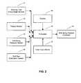
- FIG. 2is a block diagram of a directional drilling control system according to an embodiment of the present invention.
- FIG. 3is a pictorial view of a driller's screen according to an embodiment of the present invention.
- FIG. 4is a flowchart illustrating the steps of an embodiment of the method of the invention for drilling a bore hole
- FIG. 5is a flowchart illustrating the steps of an embodiment of the method of the invention for initiating the drilling of a bore hole
- FIG. 6is a flowchart illustrating the steps of an embodiment of the method of the invention for alternating rotary drilling and slide drilling.
- FIG. 1shows a schematic elevational view of a directional drilling system appropriate for the present invention.
- a drilling rigis designated generally by reference numeral 11 .
- the rig 11 depicted in FIG. 1is a land rig, but this is for illustrative purposes only, and is not intended to be a restriction on the invention.
- the method and system of the present inventionwould apply equally to water-borne rigs, including, but not limited to, jack-up rigs, semisubmersible rigs, and drill ships.
- the rig 11includes a derrick 13 that is supported on the ground above a rig floor 15 .
- the rig 11includes lifting gear, which includes a crown block 17 mounted to the derrick 13 and a traveling block 19 .
- the crown block 17 and the traveling block 19are interconnected by a cable 21 that is driven by a draw works 23 to control the upward and downward movement of the traveling block 19 .
- the traveling block 19carries a hook 25 from which is suspended a top drive 27 .
- the top drive 27rotatably supports a drill string, designated generally by reference numeral 35 , in a well bore 33 .
- the top drive 27can be operated to rotate the drill string 35 in either direction.
- the drill string 35can be coupled to the top drive 27 through an instrumented top sub 29 , although this is not a limitation on the scope of the invention.
- a surface drill string torque sensor 53can be provided. However, the location of the surface torque sensor 53 is not a limitation on the scope off the present invention.
- a surface drill pipe orientation sensor 65that provides measurements of drill string angular position or surface tool face can be provided. However, the location of the surface drill pipe orientation sensor 65 is not a limitation of the present invention.
- the surface torque sensor 53may be implemented as a strain gage in the instrumented top sub 29 .
- the torque sensor 53may also be implemented as a current measurement device for an electric rotary table or top drive motor, or as a pressure sensor for a hydraulically operated top drive, as previously explained.
- the drill string torque sensor 53provides a signal which may be sampled electronically. Irrespective of the instrumentation used, the torque sensor 53 provides a measurement corresponding to the torque applied to the drill string at the surface by the top drive or rotary table, depending on how the drill rig is equipped. Other parameters which may be measured, and the corresponding sensors used to make the measurements, will be apparent to those skilled in the art.
- the drill string 35includes a plurality of interconnected sections of drill pipe (not shown separately) and a bottom hole assembly (BHA) 37 .
- the bottom hole assembly 37may include stabilizers, drill collars and a suite of measurement while drilling (MWD) instruments, including a directional sensor 51 .
- the directional sensor 51provides, among other measurements, tool face angle measurements that can be used according to the present invention, as well as bore hole azimuth and inclination measurements.
- a steerable drilling motor 41is connected near the bottom of the bottom hole assembly 37 .
- the steerable drilling motor 41can be, but is not limited to, a positive displacement motor, a turbine, or an electric motor that can turn the drill bit 40 independently of the rotation of the drill string 35 .
- the tool face angle of the drilling motoris used to correct or adjust the azimuth and inclination of the bore hole 33 during slide drilling.
- Drilling fluidis delivered to the interior of the drill string 35 by mud pumps 43 through a mud hose 45 .
- the drill string 35is rotated within the bore hole 33 by the top drive 27 .
- the top drive 27is slidingly mounted on parallel vertically extending rails (not shown) to resist rotation as torque is applied to the drill string 35 .
- the drill string 35is held rotationally in place by the top drive 27 while the drill bit 40 is rotated by the drilling motor 41 .
- the drilling motor 41is ultimately supplied with drilling fluid by the mud pumps 43 through the mud hose 45 and through the drill string 35 .
- the drillercan operate the top drive 27 to change the tool face orientation of the drilling motor 41 by rotating the entire drill string 35 .
- a top drive 27 for rotating the drill string 35is illustrated in FIG. 1 , but that is for illustrative purposes only, and is not intended to limit the scope of the present invention.
- the present inventionmay also be used in connection with other equipment used to turn the drill string at the earth's surface.
- One example of such other equipmentis a rotary table and Kelly bushing (neither shown) to apply torque to the drill string 35 .
- the cuttings produced as the drill bit 40 drills into the earthare carried out of the bore hole 33 by the drilling fluid supplied by the mud pumps 43 .
- the discharge side of the mud pumps 43includes a drill string pressure sensor 63 .
- the drill string pressure sensor 63may be in the form of a pump pressure transducer coupled to the mud hose 45 running from the mud pumps 43 to the top drive 27 .
- the pressure sensor 63makes measurements corresponding to the pressure inside the drill string 35 .
- the actual location of the pressure sensor 63is not intended to limit the scope of the invention.
- Some embodiments of the instrumented top sub 29may include a pressure sensor.
- FIG. 2shows a block diagram of a directional drilling control system according to an embodiment of the present invention.
- the system of the present inventionincludes a steering tool or directional sensor 51 which produces a signal indicative of the tool face angle of the steerable motor 41 .
- the systemincludes a drill string torque sensor 53 .
- the torque sensor 53provides a measure of the torque applied to the drill string at the surface.
- the systemincludes a drill string pressure sensor 63 that provides measurements of the drill string pressure.
- the systemincludes a surface drill pipe orientation sensor 65 that provides measurements of drill string torque.
- the outputs of directional sensor 51 , the torque sensor 53 , the pressure sensor 63 , and the drill pipe orientation sensor 65are received at or otherwise operatively coupled to a processor 55 .
- the processor 55is programmed, according to the present invention, to process signals received from the sensors 51 , 53 , 63 , and 65 .
- the processoralso receives user input from user input devices, indicated generally at 57 .
- User input devices 57may include, but are not limited to, a keyboard, a touch screen, a mouse, a light pen, or a keypad.
- the processor 55may also provide visual output to a display 59 .
- the processoralso provides output to a drill string rotation controller 61 that operates the top drive or rotary table to rotate the drill string in a manner according to the present invention.
- FIG. 3shows a pictorial view of a driller's screen according to an embodiment of the present invention.
- Driller's screen 71displays pertinent drilling information to the driller (drilling rig operator) and provides a graphical user interface to the system of the present invention.
- the user interfacemay, for example, be in the form of a touch screen such as sold under the trade name FANUC by General Electric Co., Fairfield, Conn., USA.
- Screen 71includes a tool face indicator 73 , which displays the tool face angle derived from the output of the steering tool.
- the tool face indicator 73is implemented as a combination dial and numerical indicator.
- Screen 71includes a pump pressure indicator 75 , an off-bottom pressure indicator 77 , and a differential pressure indicator 79 .
- the pump pressure indicator 75displays drilling fluid pressure information derived from the pressure sensor 63 ( FIG. 2 ).
- the off-bottom pressure indicator 77displays drilling fluid pressure when the drill bit is off the bottom of the bore hole (and thus the steerable drilling motor is exerting substantially no torque).
- the differential pressure indicator 79displays the difference between the off-bottom pressure and the drilling fluid pressure when the drill bit is on the bottom of the bore hole and is drilling an earth formation, and thus the drilling motor is exerting substantial torque.
- differential pressureis related to weight on bit.
- weight on bitis typically inferred from differential pressure.
- the drillerbegins circulating drilling fluid while the drill bit is off the bottom of the bore hole.
- the drillercan input the off-bottom drilling fluid pressure to the system.
- the off-bottom pressureis displayed in the off-bottom indicator 77 and used to calculate the differential pressure for display in the differential indicator 79 .
- the off-bottom pressure indicator 77is accompanied by off-bottom pressure controls.
- An up arrow control 81increases the off-bottom pressure when activated, while a down arrow control 83 decreases the off-bottom pressure when activated.
- the Screen 71includes a RSM (Rotary Steerable Motor) Control Set 85 .
- the RSM Control Setincludes six combination controls with both up arrow and down arrow controls and numerical displays. The controls and displays are for the trigger value 87 , the range 89 for the trigger value, the left torque value 91 , the idle percent 93 , the slide time 95 , and the rotate time 97 .
- An actual trigger indicator 101displays the measured result for the driller.
- a trigger value selector 105allows the driller to choose which type of trigger to use.
- Screen 71also displays the inclination indicator 107 , azimuth indicator 109 , and torque indicator 111 beneath and to the right of the tool face indicator 73 .
- a graphical display 113shows plots of differential pressure vs. time 115 and torque vs. time 117 for the driller. Surface rate of penetration, bit depth, and hook load (weight of the drill string measured at the earth's surface) are displayed in indicator boxes 119 , 121 , and 123 , respectively.
- FIG. 4shows a flowchart illustrating an embodiment of the method of the invention for drilling a bore hole.
- the flowchart in FIG. 4gives a general view of the method of the invention for alternating between rotary drilling and slide drilling in drilling a directional well. Details of the method are described further in the flowcharts discussed with reference to FIGS. 5 and 6 , below.
- the inventionin general terms is a method for directionally drilling a bore hole with a steerable drilling motor.
- the methodincludes alternating between two drilling modes with two different drill string rotation rates to keep the tool face angle near a desired orientation for as much of the time as possible.
- the methodsets targets to aid in determining when drilling at a particular drill string rotation rate has continued long enough.
- the methoduses triggers to determine when to take a specific action, such as changing from the first to the second drill string rotation rate. For example, a first target is checked to determine when the drilling at the first rotation rate has gone on long enough. Then a first trigger is checked to determine when to change to the second rotation rate. Then, a second target is checked to determine when drilling at the second rotation rate has gone on long enough. The method returns to the first rotation rate to continue the process of alternating between the two drilling rotation rates.
- the first target for determining when to start checking for the first triggeris a parameter that is based on weight on bit. This parameter would include, but not be limited to, weight on bit itself, differential pressure (defined above), or downhole reactive torque.
- the first targetis a pre-selected time period. The procedures for determining whether the first target is met are described below with reference to the flowchart in FIG. 6 .
- the first rotation rateis changed to a second rotation rate when a first trigger is substantially met.
- the drill string rotation rate of the rotary drillingis decreased to a slower rate.
- the rotation speed for rotary drillingalternates between a first, high rotation rate, such as about 40 revolutions per minute (rpm), and a second, low rotation rate, such as about 5-10 rpm.
- the slow down in rotation rateis not enough to change the drilling mode from rotary drilling to slide drilling.
- the slow downonly causes the surface applied torque to the drill string to temporarily decline below rotary drilling torque (the amount of surface applied torque needed to keep the drill string rotating) during the drilling at the second rotation rate for a short period of time.
- the purpose of slowing the rotation rate of the drill stringis to spend more time drilling within a range, for example 90°, of a desired tool face angle than drilling in a range away from the desired tool face angle.
- the first trigger for determining when to change from the first rotation rate to the second rotation rateis a measurement of tool face angle.
- the first trigger for changing rotation ratesis substituted by making the changes after preselected time periods. The procedures for determining whether the first trigger is substantially met are described below with reference to the flowchart in FIG. 6 .
- drillingis continued at the second rotation rate until a second target is substantially met.
- the drilling rateis a slow rotation rate as described above and so the drilling mode remains rotary drilling.
- the second rotation rateis substantially zero and so the drilling mode is slide drilling.
- the drilling modeis changing from rotary drilling at the first rotation rate to slide drilling at the second, substantially zero rotation rate and then back to the first rotation rate.
- the second target for changing back to rotary drilling at the first rotation rateis a parameter that is based on weight on bit. This parameter would include, but not be limited to, weight on bit itself, differential pressure, or downhole reactive torque.
- the second target for changing backis a pre-selected time period. The procedures for determining whether the second target is substantially met are described in more detail below with reference to the flowchart in FIG. 6 .
- the tool face angle during the second rate of rotationshould be substantially the same every time.
- the tool face during the second rate of rotationcan be sufficiently controlled.
- the first trigger pointmay be adjusted until the tool face angle during the second rate of rotation (typically slide drilling) begins to fall into a desired tool face window.
- the processreturns to 42 to repeat elements 42 - 44 , thus alternating between rotary drilling at the first rotation rate and rotary or slide drilling at the second rotation rate.
- the method of the inventionmay be performed manually or automated. Automation increases the accuracy and repeatability of the process, which thus increases the success rate or effectiveness of using the present invention.
- FIG. 5shows a flowchart illustrating an embodiment of the method of the invention for initiating the drilling of a bore hole.
- the flowchart in FIG. 5describes in more detail the method of the invention shown at 41 of the flowchart in FIG. 4 , above.
- drilling fluid circulationis initiated.
- drill string rotationis initiated. The driller starts rotating the drill string using the top drive, rotary table, or other equipment on the drill rig.
- the rate of drill string rotationis increased to the first rotation rate.
- the first rotation rateis a desired operating rotation rate.
- off-bottom pump pressureis determined. The off-bottom pressure may then be used later to calculate the differential pressure.
- axially advancing the drill string(drilling ahead) is initiated.
- the rate of advancing the drill stringis adjusted to a desired operating advancing rate.
- the operating advancing rateis preferably the rate that maintains the desired differential pressure or weight on bit (hook load). Alternatively, the operating advancing rate is the rate that maintains a desired surface-measured rate of penetration.
- on-bottom pump pressureis monitored.
- differential pressureis calculated from the difference of the off-bottom pressure from 54 and the on-bottom pressure from 57 .
- torqueis monitored.
- drill pipe orientation angle(surface tool face angle) is monitored.
- FIG. 6shows a flowchart illustrating an embodiment of the method of the invention for alternating rotary drilling and slide drilling.
- the flowchart in FIG. 6describes in more detail the method of the invention shown at 42 - 43 of the flowchart in FIG. 4 , above.
- the drill stringis rotated at the first rotation rate.
- the first rotation rateis a desired operating rotation rate. The driller brings the rate of rotation of the drill string up to the operating rate.
- the drill stringis axially advanced at an operating advancing rate.
- the drillerbrings the rate of drill string advancement up to the operating rate.
- the operating advancement rateis preferably the rate that maintains the desired differential pressure or weight on bit.
- the operating advancing rateis the rate that maintains a desired surface rate of penetration.
- the first targetis differential pressure.
- the drillercan monitor the differential pressure on the driller's screen until a desired target value is substantially met.
- the target differential pressure valueis preferably the recommended operating differential pressure of the drilling motor, perhaps less a safety factor.
- the target differential pressure valuemay be defined within a range of the first target value.
- the first targetis time.
- a time valuecan be preset. Typically, this time value may be of the order of approximately 10 seconds. This time value is preferably selected so that the differential pressure has had sufficient time to rise to the desired level.
- step 64the process continues to step 64 to begin checking for the first trigger value.
- the first trigger value to be metis defined within a range on both sides of the trigger value. Using a range is a more realistic approach to meeting a trigger value.
- the first triggeris tool face angle.
- the drillermay monitor tool face angle from the driller's screen and determine from steering tool measurements the prevailing tool face angle during the second rotation rate (typically slide drilling).
- the desired tool face angle of the current drilling cycleis the desired end, the first trigger tool face angle will have to be a different value to account for the inertia of the drill string. Stopping rotation of the drill string at the surface does not instantly stop the drill string at the bit.
- the first trigger valuewill have to be a value of the tool face angle that leads to the desired tool face angle when the tool face stops changing orientation. Discovering an appropriate trigger value may take a process of trial and error or may be gleaned from previous experience.
- the first triggeris not based on a given parameter, but is simply a random action.
- substantially closeis defined as within a pre-selected range of the desired tool face angle.
- torquecan be a trigger. Torque may be measured at the bottom-hole, at the surface, or anywhere in the bore hole.
- step 65when the first trigger value is substantially met, then the process continues to step 65 to change over to drilling at the second rotation rate.
- the rate of rotation of the drill stringis changed to the second rotation rate.
- the rate of rotationis decreased from a relatively higher first rotation rate to a relatively lower second rotation rate.
- the second rotation rateis substantially zero.
- the drilling mode at a zero rotation rateis now slide drilling instead of rotary drilling.
- the rate of advance of the drill stringis kept constant.
- the surface rate of penetration of the drill stringis kept constant.
- a left hand torqueis applied. This is an optional step that is applied when needed.
- Left hand torquealso called a left torque bump, is the amount of counter-clockwise (“to the left”, as it is known in the art) torque applied to the drill string at the surface. Since normal rotation of the drill pipe is clockwise (“to the right”, as it is known in the art), left hand torque is a opposite direction drill pipe rotation.
- a left torque bumpis an extra small amount of left hand torque applied to hold the drill string relatively motionless during the slide drilling step. In practice, the left hand torque is applied until a second trigger, a preset left torque value, is reached before settling to the second rotation rate.
- the drill stringis axially advanced at the operating advancing rate.
- the operating advancing ratemay be the rate that maintains a desired differential pressure, weight on bit, or surface rate of penetration.
- the second targetis differential pressure.
- the drillercan monitor the differential pressure on the driller's screen until a desired target value is substantially met.
- the differential pressure valueis decreasing and the driller can pick a value close to zero as the second target value.
- the target differential pressure valuemay be defined within a range of the second target value.
- the second targetis time.
- a time valuecan be preset on the driller's screen. Typically, this time value may be of the order of approximately 10 seconds. This time value is preferably selected so that the differential pressure has had sufficient time to decrease to the desired level.
- the processreturns to 61 to repeat rotary drilling at the first rotation rate again.
- the first trigger valueis adjusted, if needed.
- the first trigger valueis adjusted until the tool face angle during the second rate of rotation begins to fall into the desired tool face window. This adjustment may take a few cycles of trial and error. As a consequence, the downhole tool face during the second rate of rotation can be controlled sufficiently to be substantially the same every time.
Landscapes
- Life Sciences & Earth Sciences (AREA)
- Engineering & Computer Science (AREA)
- Geology (AREA)
- Mining & Mineral Resources (AREA)
- Physics & Mathematics (AREA)
- Environmental & Geological Engineering (AREA)
- Fluid Mechanics (AREA)
- General Life Sciences & Earth Sciences (AREA)
- Geochemistry & Mineralogy (AREA)
- Earth Drilling (AREA)
- Drilling And Boring (AREA)
Abstract
Description
Claims (15)
Priority Applications (4)
| Application Number | Priority Date | Filing Date | Title |
|---|---|---|---|
| US11/524,009US7810584B2 (en) | 2006-09-20 | 2006-09-20 | Method of directional drilling with steerable drilling motor |
| CA2663533ACA2663533C (en) | 2006-09-20 | 2007-09-11 | Method of directional drilling with steerable drilling motor |
| PCT/US2007/078083WO2008036522A2 (en) | 2006-09-20 | 2007-09-11 | Method of directional drilling with steerable drilling motor |
| GB0905181AGB2455463A (en) | 2006-09-20 | 2009-03-26 | Method of directional drilling with steerable drilling motor |
Applications Claiming Priority (1)
| Application Number | Priority Date | Filing Date | Title |
|---|---|---|---|
| US11/524,009US7810584B2 (en) | 2006-09-20 | 2006-09-20 | Method of directional drilling with steerable drilling motor |
Publications (2)
| Publication Number | Publication Date |
|---|---|
| US20080066958A1 US20080066958A1 (en) | 2008-03-20 |
| US7810584B2true US7810584B2 (en) | 2010-10-12 |
Family
ID=39187388
Family Applications (1)
| Application Number | Title | Priority Date | Filing Date |
|---|---|---|---|
| US11/524,009Active2027-04-08US7810584B2 (en) | 2006-09-20 | 2006-09-20 | Method of directional drilling with steerable drilling motor |
Country Status (4)
| Country | Link |
|---|---|
| US (1) | US7810584B2 (en) |
| CA (1) | CA2663533C (en) |
| GB (1) | GB2455463A (en) |
| WO (1) | WO2008036522A2 (en) |
Cited By (33)
| Publication number | Priority date | Publication date | Assignee | Title |
|---|---|---|---|---|
| US20100133008A1 (en)* | 2006-09-27 | 2010-06-03 | Halliburton Energy Services, Inc | Monitor and control of directional drilling operations and simulations |
| US8387720B1 (en) | 2012-05-31 | 2013-03-05 | Larry G. Keast | Drilling rig with a control system for rotationally rocking a drill string with a top drive |
| US8631882B1 (en) | 2010-12-07 | 2014-01-21 | Larry G. Keast | Drilling rig with torque measuring top drive |
| US8636056B1 (en) | 2010-12-07 | 2014-01-28 | Larry G. Keast | Drilling rig with torque track slide assembly |
| WO2014099309A1 (en) | 2012-12-18 | 2014-06-26 | Schlumberger Canada Limited | Automated directional drilling system and method using steerable motors |
| US9145768B2 (en) | 2012-07-03 | 2015-09-29 | Schlumberger Technology Corporation | Method for reducing stick-slip during wellbore drilling |
| US9249655B1 (en)* | 2012-05-31 | 2016-02-02 | Larry G. Keast | Control system for a top drive |
| US9359882B2 (en) | 2006-09-27 | 2016-06-07 | Halliburton Energy Services, Inc. | Monitor and control of directional drilling operations and simulations |
| US9404307B2 (en) | 2014-06-02 | 2016-08-02 | Schlumberger Technology Corporation | Method and system for directional drilling |
| US9822633B2 (en) | 2013-10-22 | 2017-11-21 | Schlumberger Technology Corporation | Rotational downlinking to rotary steerable system |
| CN107489382A (en)* | 2016-03-16 | 2017-12-19 | 刘玉友 | Well drilling top drive and the application method of safety platform protection device |
| US9932821B2 (en) | 2014-10-22 | 2018-04-03 | Halliburton Energy Services Inc. | Bend angle sensing assembly and method of use |
| US10018028B2 (en)* | 2011-12-22 | 2018-07-10 | Motive Drilling Technologies, Inc. | System and method for surface steerable drilling |
| US10094209B2 (en) | 2014-11-26 | 2018-10-09 | Nabors Drilling Technologies Usa, Inc. | Drill pipe oscillation regime for slide drilling |
| CN109025801A (en)* | 2018-07-06 | 2018-12-18 | 中国石油集团川庆钻探工程有限公司 | Method for determining swing range of sliding drilling drill column |
| US10435951B2 (en) | 2014-04-29 | 2019-10-08 | Halliburton Energy Services Inc. | Tool face control of a downhole tool with reduced drill string friction |
| US10487642B2 (en) | 2013-10-28 | 2019-11-26 | Schlumberger Technology Corporation | Frequency analysis of drilling signals |
| US10808517B2 (en) | 2018-12-17 | 2020-10-20 | Baker Hughes Holdings Llc | Earth-boring systems and methods for controlling earth-boring systems |
| US10883356B2 (en) | 2014-04-17 | 2021-01-05 | Schlumberger Technology Corporation | Automated sliding drilling |
| US11028684B2 (en) | 2011-12-22 | 2021-06-08 | Motive Drilling Technologies, Inc. | System and method for determining the location of a bottom hole assembly |
| US11085283B2 (en) | 2011-12-22 | 2021-08-10 | Motive Drilling Technologies, Inc. | System and method for surface steerable drilling using tactical tracking |
| US11106185B2 (en) | 2014-06-25 | 2021-08-31 | Motive Drilling Technologies, Inc. | System and method for surface steerable drilling to provide formation mechanical analysis |
| US11236601B2 (en) | 2018-01-16 | 2022-02-01 | Nabors Drilling Technologies Usa, Inc. | System and method of automating a slide drilling operation |
| US11286719B2 (en) | 2011-12-22 | 2022-03-29 | Motive Drilling Technologies, Inc. | Systems and methods for controlling a drilling path based on drift estimates |
| US11346215B2 (en) | 2018-01-23 | 2022-05-31 | Baker Hughes Holdings Llc | Methods of evaluating drilling performance, methods of improving drilling performance, and related systems for drilling using such methods |
| US11352871B2 (en) | 2020-05-11 | 2022-06-07 | Schlumberger Technology Corporation | Slide drilling overshot control |
| US11624666B2 (en) | 2018-06-01 | 2023-04-11 | Schlumberger Technology Corporation | Estimating downhole RPM oscillations |
| US11808133B2 (en) | 2019-05-28 | 2023-11-07 | Schlumberger Technology Corporation | Slide drilling |
| US11814943B2 (en) | 2020-12-04 | 2023-11-14 | Schlumberger Technoloyg Corporation | Slide drilling control based on top drive torque and rotational distance |
| US11916507B2 (en) | 2020-03-03 | 2024-02-27 | Schlumberger Technology Corporation | Motor angular position control |
| US11933156B2 (en) | 2020-04-28 | 2024-03-19 | Schlumberger Technology Corporation | Controller augmenting existing control system |
| US11933158B2 (en) | 2016-09-02 | 2024-03-19 | Motive Drilling Technologies, Inc. | System and method for mag ranging drilling control |
| US12196069B2 (en) | 2014-06-25 | 2025-01-14 | Motive Drilling Technologies, Inc. | Surface steerable drilling system for use with rotary steerable system |
Families Citing this family (18)
| Publication number | Priority date | Publication date | Assignee | Title |
|---|---|---|---|---|
| US8672055B2 (en)* | 2006-12-07 | 2014-03-18 | Canrig Drilling Technology Ltd. | Automated directional drilling apparatus and methods |
| NO334262B1 (en)* | 2007-06-20 | 2014-01-20 | 2TD Drilling AS | Device for directional control of drilling tools |
| AU2010244940B2 (en)* | 2009-05-06 | 2016-06-09 | Dynomax Drilling Tools Inc. | Slide reamer and stabilizer tool |
| US8939234B2 (en)* | 2009-09-21 | 2015-01-27 | National Oilwell Varco, L.P. | Systems and methods for improving drilling efficiency |
| US8534354B2 (en)* | 2010-03-05 | 2013-09-17 | Schlumberger Technology Corporation | Completion string deployment in a subterranean well |
| CN103015967B (en)* | 2010-04-12 | 2016-01-20 | 国际壳牌研究有限公司 | The method in the tool-face direction of bottom hole assemblies is controlled for slide drilling |
| US20120024606A1 (en)* | 2010-07-29 | 2012-02-02 | Dimitrios Pirovolou | System and method for direction drilling |
| US20130014992A1 (en)* | 2011-03-01 | 2013-01-17 | The Charles Machine Works, Inc. | Data Transfer In A Two-Pipe Directional Drilling System |
| CN102900365B (en)* | 2012-10-09 | 2014-10-29 | 东南大学 | Embedded type system-based control device for horizontal directional drill |
| WO2014134736A1 (en) | 2013-03-07 | 2014-09-12 | Dynomax Drilling Tools Inc. | Downhole motor |
| US10577864B2 (en) | 2014-06-24 | 2020-03-03 | Iggillis Holdings Inc. | Method and system for drilling a borehole |
| CA2959497C (en)* | 2014-08-28 | 2022-11-22 | Schlumberger Canada Limited | Method and system for directional drilling |
| US20170241253A1 (en)* | 2014-10-15 | 2017-08-24 | Schlumberger Technology Corporation | Method and apparatus for directional drilling using wired drill pipe |
| WO2016081774A1 (en)* | 2014-11-20 | 2016-05-26 | Schlumberger Canada Limited | Continuous downlinking while drilling |
| US20180347281A1 (en)* | 2015-12-04 | 2018-12-06 | Schlumberger Technology Corporation | Automated directional drilling system and method using steerable drilling motors |
| WO2017095974A1 (en)* | 2015-12-04 | 2017-06-08 | Schlumberger Technology Corporation | Automated directional drilling system and method using steerable drilling motors |
| CN109083595B (en)* | 2018-09-30 | 2020-05-01 | 四川宏华电气有限责任公司 | Fast sliding guiding drilling method |
| CN118900947A (en)* | 2022-03-04 | 2024-11-05 | 吉奥奎斯特系统公司 | System and method for determining torque transfer from the surface to a drill bit |
Citations (21)
| Publication number | Priority date | Publication date | Assignee | Title |
|---|---|---|---|---|
| US4739842A (en)* | 1984-05-12 | 1988-04-26 | Eastman Christensen Company | Apparatus for optional straight or directional drilling underground formations |
| US5107939A (en)* | 1990-09-21 | 1992-04-28 | Ensco Technology Company | Electrically conducting an orientation signal in a directionally drilled well |
| US5458208A (en)* | 1994-07-05 | 1995-10-17 | Clarke; Ralph L. | Directional drilling using a rotating slide sub |
| US5465799A (en)* | 1994-04-25 | 1995-11-14 | Ho; Hwa-Shan | System and method for precision downhole tool-face setting and survey measurement correction |
| US6050348A (en) | 1997-06-17 | 2000-04-18 | Canrig Drilling Technology Ltd. | Drilling method and apparatus |
| US6158533A (en)* | 1998-04-09 | 2000-12-12 | Halliburton Energy Services, Inc. | Adjustable gauge downhole drilling assembly |
| US6415878B1 (en)* | 1998-01-21 | 2002-07-09 | Halliburton Energy Services, Inc. | Steerable rotary drilling device |
| US20020104685A1 (en)* | 2000-11-21 | 2002-08-08 | Pinckard Mitchell D. | Method of and system for controlling directional drilling |
| US6438495B1 (en)* | 2000-05-26 | 2002-08-20 | Schlumberger Technology Corporation | Method for predicting the directional tendency of a drilling assembly in real-time |
| US20040118608A1 (en)* | 2002-12-19 | 2004-06-24 | Marc Haci | Method of and apparatus for directional drilling |
| US20040118612A1 (en)* | 2002-12-19 | 2004-06-24 | Marc Haci | Method of and apparatus for directional drilling |
| US20040195004A1 (en)* | 2003-04-01 | 2004-10-07 | Power David J. | Automatic drilling system |
| US20040222023A1 (en)* | 2003-05-10 | 2004-11-11 | Marc Haci | Continuous on-bottom directional drilling method and system |
| US20050077084A1 (en)* | 2003-10-09 | 2005-04-14 | John Kracik | Make-up control system for tubulars |
| US20050133259A1 (en)* | 2003-12-23 | 2005-06-23 | Varco I/P, Inc. | Autodriller bit protection system and method |
| US20050194183A1 (en)* | 2004-03-04 | 2005-09-08 | Gleitman Daniel D. | Providing a local response to a local condition in an oil well |
| US20060081399A1 (en)* | 2004-10-20 | 2006-04-20 | Comprehensive Power, Inc. | Method and control system for directional drilling |
| US20060185900A1 (en)* | 2005-02-18 | 2006-08-24 | Pathfinder Energy Services, Inc. | Programming method for controlling a downhole steering tool |
| US20060266555A1 (en)* | 1998-12-21 | 2006-11-30 | Chen Chen-Kang D | Steerable drilling system and method |
| US20060283632A1 (en)* | 2005-06-17 | 2006-12-21 | Aps Technology, Inc. | System and method for acquiring information during underground drilling operations |
| US7306054B2 (en)* | 2002-04-19 | 2007-12-11 | Hutchinson Mark W | Method for improving drilling depth measurements |
Family Cites Families (1)
| Publication number | Priority date | Publication date | Assignee | Title |
|---|---|---|---|---|
| US5361033A (en)* | 1991-07-25 | 1994-11-01 | Texas Instruments Incorporated | On chip bi-stable power-spike detection circuit |
- 2006
- 2006-09-20USUS11/524,009patent/US7810584B2/enactiveActive
- 2007
- 2007-09-11CACA2663533Apatent/CA2663533C/enactiveActive
- 2007-09-11WOPCT/US2007/078083patent/WO2008036522A2/enactiveApplication Filing
- 2009
- 2009-03-26GBGB0905181Apatent/GB2455463A/ennot_activeWithdrawn
Patent Citations (25)
| Publication number | Priority date | Publication date | Assignee | Title |
|---|---|---|---|---|
| US4739842A (en)* | 1984-05-12 | 1988-04-26 | Eastman Christensen Company | Apparatus for optional straight or directional drilling underground formations |
| US5107939A (en)* | 1990-09-21 | 1992-04-28 | Ensco Technology Company | Electrically conducting an orientation signal in a directionally drilled well |
| US5465799A (en)* | 1994-04-25 | 1995-11-14 | Ho; Hwa-Shan | System and method for precision downhole tool-face setting and survey measurement correction |
| US5458208A (en)* | 1994-07-05 | 1995-10-17 | Clarke; Ralph L. | Directional drilling using a rotating slide sub |
| US6050348A (en) | 1997-06-17 | 2000-04-18 | Canrig Drilling Technology Ltd. | Drilling method and apparatus |
| US6415878B1 (en)* | 1998-01-21 | 2002-07-09 | Halliburton Energy Services, Inc. | Steerable rotary drilling device |
| US6158533A (en)* | 1998-04-09 | 2000-12-12 | Halliburton Energy Services, Inc. | Adjustable gauge downhole drilling assembly |
| US7147066B2 (en)* | 1998-12-21 | 2006-12-12 | Halliburton Energy Services, Inc. | Steerable drilling system and method |
| US20060266555A1 (en)* | 1998-12-21 | 2006-11-30 | Chen Chen-Kang D | Steerable drilling system and method |
| US6438495B1 (en)* | 2000-05-26 | 2002-08-20 | Schlumberger Technology Corporation | Method for predicting the directional tendency of a drilling assembly in real-time |
| US20020104685A1 (en)* | 2000-11-21 | 2002-08-08 | Pinckard Mitchell D. | Method of and system for controlling directional drilling |
| US7306054B2 (en)* | 2002-04-19 | 2007-12-11 | Hutchinson Mark W | Method for improving drilling depth measurements |
| US6802378B2 (en) | 2002-12-19 | 2004-10-12 | Noble Engineering And Development, Ltd. | Method of and apparatus for directional drilling |
| US6918453B2 (en) | 2002-12-19 | 2005-07-19 | Noble Engineering And Development Ltd. | Method of and apparatus for directional drilling |
| US20040118612A1 (en)* | 2002-12-19 | 2004-06-24 | Marc Haci | Method of and apparatus for directional drilling |
| US20040118608A1 (en)* | 2002-12-19 | 2004-06-24 | Marc Haci | Method of and apparatus for directional drilling |
| US20040195004A1 (en)* | 2003-04-01 | 2004-10-07 | Power David J. | Automatic drilling system |
| US20040222023A1 (en)* | 2003-05-10 | 2004-11-11 | Marc Haci | Continuous on-bottom directional drilling method and system |
| US7096979B2 (en) | 2003-05-10 | 2006-08-29 | Noble Drilling Services Inc. | Continuous on-bottom directional drilling method and system |
| US20050077084A1 (en)* | 2003-10-09 | 2005-04-14 | John Kracik | Make-up control system for tubulars |
| US20050133259A1 (en)* | 2003-12-23 | 2005-06-23 | Varco I/P, Inc. | Autodriller bit protection system and method |
| US20050194183A1 (en)* | 2004-03-04 | 2005-09-08 | Gleitman Daniel D. | Providing a local response to a local condition in an oil well |
| US20060081399A1 (en)* | 2004-10-20 | 2006-04-20 | Comprehensive Power, Inc. | Method and control system for directional drilling |
| US20060185900A1 (en)* | 2005-02-18 | 2006-08-24 | Pathfinder Energy Services, Inc. | Programming method for controlling a downhole steering tool |
| US20060283632A1 (en)* | 2005-06-17 | 2006-12-21 | Aps Technology, Inc. | System and method for acquiring information during underground drilling operations |
Non-Patent Citations (1)
| Title |
|---|
| Maidla, Haci "Understanding Torque: The key to slide-drilling directional wells" Society of Petroleum Engineers, IADC/SPE 87162 Drilling conference, presented Mar. 2-4, 2004.* |
Cited By (45)
| Publication number | Priority date | Publication date | Assignee | Title |
|---|---|---|---|---|
| US9359882B2 (en) | 2006-09-27 | 2016-06-07 | Halliburton Energy Services, Inc. | Monitor and control of directional drilling operations and simulations |
| US20100133008A1 (en)* | 2006-09-27 | 2010-06-03 | Halliburton Energy Services, Inc | Monitor and control of directional drilling operations and simulations |
| US9915139B2 (en) | 2006-09-27 | 2018-03-13 | Halliburton Energy Services, Inc. | Monitor and control of directional drilling operations and simulations |
| US9103195B2 (en)* | 2006-09-27 | 2015-08-11 | Halliburton Energy Services, Inc. | Monitor and control of directional drilling operations and simulations |
| US8631882B1 (en) | 2010-12-07 | 2014-01-21 | Larry G. Keast | Drilling rig with torque measuring top drive |
| US8636056B1 (en) | 2010-12-07 | 2014-01-28 | Larry G. Keast | Drilling rig with torque track slide assembly |
| US11286719B2 (en) | 2011-12-22 | 2022-03-29 | Motive Drilling Technologies, Inc. | Systems and methods for controlling a drilling path based on drift estimates |
| US11085283B2 (en) | 2011-12-22 | 2021-08-10 | Motive Drilling Technologies, Inc. | System and method for surface steerable drilling using tactical tracking |
| US10995602B2 (en) | 2011-12-22 | 2021-05-04 | Motive Drilling Technologies, Inc. | System and method for drilling a borehole |
| US11047222B2 (en) | 2011-12-22 | 2021-06-29 | Motive Drilling Technologies, Inc. | System and method for detecting a mode of drilling |
| US12297736B2 (en) | 2011-12-22 | 2025-05-13 | Motive Drilling Technologies, Inc. | Systems and methods for controlling a drilling path based on drift estimates |
| US11028684B2 (en) | 2011-12-22 | 2021-06-08 | Motive Drilling Technologies, Inc. | System and method for determining the location of a bottom hole assembly |
| US12241356B2 (en) | 2011-12-22 | 2025-03-04 | Motive Drilling Technologies, Inc. | System and method for drilling a borehole |
| US11828156B2 (en) | 2011-12-22 | 2023-11-28 | Motive Drilling Technologies, Inc. | System and method for detecting a mode of drilling |
| US12203361B2 (en) | 2011-12-22 | 2025-01-21 | Motive Drilling Technologies, Inc. | System and method for determining the location of a bottom hole assembly |
| US10018028B2 (en)* | 2011-12-22 | 2018-07-10 | Motive Drilling Technologies, Inc. | System and method for surface steerable drilling |
| US11982172B2 (en) | 2011-12-22 | 2024-05-14 | Motive Drilling Technologies, Inc. | System and method for drilling a borehole |
| US9249655B1 (en)* | 2012-05-31 | 2016-02-02 | Larry G. Keast | Control system for a top drive |
| US8387720B1 (en) | 2012-05-31 | 2013-03-05 | Larry G. Keast | Drilling rig with a control system for rotationally rocking a drill string with a top drive |
| US9145768B2 (en) | 2012-07-03 | 2015-09-29 | Schlumberger Technology Corporation | Method for reducing stick-slip during wellbore drilling |
| WO2014099309A1 (en) | 2012-12-18 | 2014-06-26 | Schlumberger Canada Limited | Automated directional drilling system and method using steerable motors |
| US9309760B2 (en) | 2012-12-18 | 2016-04-12 | Schlumberger Technology Corporation | Automated directional drilling system and method using steerable motors |
| US9822633B2 (en) | 2013-10-22 | 2017-11-21 | Schlumberger Technology Corporation | Rotational downlinking to rotary steerable system |
| US10487642B2 (en) | 2013-10-28 | 2019-11-26 | Schlumberger Technology Corporation | Frequency analysis of drilling signals |
| US10883356B2 (en) | 2014-04-17 | 2021-01-05 | Schlumberger Technology Corporation | Automated sliding drilling |
| US10435951B2 (en) | 2014-04-29 | 2019-10-08 | Halliburton Energy Services Inc. | Tool face control of a downhole tool with reduced drill string friction |
| US9404307B2 (en) | 2014-06-02 | 2016-08-02 | Schlumberger Technology Corporation | Method and system for directional drilling |
| US11106185B2 (en) | 2014-06-25 | 2021-08-31 | Motive Drilling Technologies, Inc. | System and method for surface steerable drilling to provide formation mechanical analysis |
| US12196069B2 (en) | 2014-06-25 | 2025-01-14 | Motive Drilling Technologies, Inc. | Surface steerable drilling system for use with rotary steerable system |
| US9932821B2 (en) | 2014-10-22 | 2018-04-03 | Halliburton Energy Services Inc. | Bend angle sensing assembly and method of use |
| US10094209B2 (en) | 2014-11-26 | 2018-10-09 | Nabors Drilling Technologies Usa, Inc. | Drill pipe oscillation regime for slide drilling |
| CN107489382B (en)* | 2016-03-16 | 2019-06-21 | 东营市汉德自动化集成有限公司 | The application method of well drilling top drive and safety platform collision-proof protector |
| CN107489382A (en)* | 2016-03-16 | 2017-12-19 | 刘玉友 | Well drilling top drive and the application method of safety platform protection device |
| US11933158B2 (en) | 2016-09-02 | 2024-03-19 | Motive Drilling Technologies, Inc. | System and method for mag ranging drilling control |
| US11236601B2 (en) | 2018-01-16 | 2022-02-01 | Nabors Drilling Technologies Usa, Inc. | System and method of automating a slide drilling operation |
| US11346215B2 (en) | 2018-01-23 | 2022-05-31 | Baker Hughes Holdings Llc | Methods of evaluating drilling performance, methods of improving drilling performance, and related systems for drilling using such methods |
| US11624666B2 (en) | 2018-06-01 | 2023-04-11 | Schlumberger Technology Corporation | Estimating downhole RPM oscillations |
| CN109025801A (en)* | 2018-07-06 | 2018-12-18 | 中国石油集团川庆钻探工程有限公司 | Method for determining swing range of sliding drilling drill column |
| US10808517B2 (en) | 2018-12-17 | 2020-10-20 | Baker Hughes Holdings Llc | Earth-boring systems and methods for controlling earth-boring systems |
| US11808133B2 (en) | 2019-05-28 | 2023-11-07 | Schlumberger Technology Corporation | Slide drilling |
| US11916507B2 (en) | 2020-03-03 | 2024-02-27 | Schlumberger Technology Corporation | Motor angular position control |
| US12119775B2 (en) | 2020-03-03 | 2024-10-15 | Schlumberger Technology Corporation | Motor angular position control |
| US11933156B2 (en) | 2020-04-28 | 2024-03-19 | Schlumberger Technology Corporation | Controller augmenting existing control system |
| US11352871B2 (en) | 2020-05-11 | 2022-06-07 | Schlumberger Technology Corporation | Slide drilling overshot control |
| US11814943B2 (en) | 2020-12-04 | 2023-11-14 | Schlumberger Technoloyg Corporation | Slide drilling control based on top drive torque and rotational distance |
Also Published As
| Publication number | Publication date |
|---|---|
| WO2008036522B1 (en) | 2008-12-24 |
| US20080066958A1 (en) | 2008-03-20 |
| WO2008036522A2 (en) | 2008-03-27 |
| GB0905181D0 (en) | 2009-05-06 |
| CA2663533A1 (en) | 2008-03-27 |
| GB2455463A (en) | 2009-06-17 |
| CA2663533C (en) | 2013-07-09 |
| WO2008036522A3 (en) | 2008-10-30 |
Similar Documents
| Publication | Publication Date | Title |
|---|---|---|
| US7810584B2 (en) | Method of directional drilling with steerable drilling motor | |
| US7096979B2 (en) | Continuous on-bottom directional drilling method and system | |
| US6918453B2 (en) | Method of and apparatus for directional drilling | |
| USRE47105E1 (en) | Method and apparatus for directional drilling | |
| US9650880B2 (en) | Waveform anti-stick slip system and method | |
| AU2015270910B2 (en) | Method and system for directional drilling | |
| US7461705B2 (en) | Directional drilling control | |
| US9309760B2 (en) | Automated directional drilling system and method using steerable motors | |
| US20200095829A1 (en) | Direct wrap measurement during connection for optimal slide drilling |
Legal Events
| Date | Code | Title | Description |
|---|---|---|---|
| AS | Assignment | Owner name:SLIDER LIMITED LIABILITY COMPANY, TEXAS Free format text:ASSIGNMENT OF ASSIGNORS INTEREST;ASSIGNORS:HACI, MARC;MAIDLA, ERIC E;REEL/FRAME:021020/0389 Effective date:20080409 | |
| AS | Assignment | Owner name:SMITH INTERNATIONAL, INC., TEXAS Free format text:ASSIGNMENT OF ASSIGNORS INTEREST;ASSIGNOR:SLIDER LIMITED LIABILITY COMPANY;REEL/FRAME:022231/0317 Effective date:20080825 | |
| STCF | Information on status: patent grant | Free format text:PATENTED CASE | |
| AS | Assignment | Owner name:SCHLUMBERGER TECHNOLOGY CORPORATION, TEXAS Free format text:ASSIGNMENT OF ASSIGNORS INTEREST;ASSIGNOR:SMITH INTERNATIONAL, INC.;REEL/FRAME:029143/0015 Effective date:20121009 | |
| FPAY | Fee payment | Year of fee payment:4 | |
| MAFP | Maintenance fee payment | Free format text:PAYMENT OF MAINTENANCE FEE, 8TH YEAR, LARGE ENTITY (ORIGINAL EVENT CODE: M1552) Year of fee payment:8 | |
| MAFP | Maintenance fee payment | Free format text:PAYMENT OF MAINTENANCE FEE, 12TH YEAR, LARGE ENTITY (ORIGINAL EVENT CODE: M1553); ENTITY STATUS OF PATENT OWNER: LARGE ENTITY Year of fee payment:12 |