US7810477B2 - Oil mist removal device with oil fill - Google Patents
Oil mist removal device with oil fillDownload PDFInfo
- Publication number
- US7810477B2 US7810477B2US12/177,471US17747108AUS7810477B2US 7810477 B2US7810477 B2US 7810477B2US 17747108 AUS17747108 AUS 17747108AUS 7810477 B2US7810477 B2US 7810477B2
- Authority
- US
- United States
- Prior art keywords
- oil
- passage
- housing
- oil mist
- engine
- Prior art date
- Legal status (The legal status is an assumption and is not a legal conclusion. Google has not performed a legal analysis and makes no representation as to the accuracy of the status listed.)
- Active, expires
Links
Images


Classifications
- F—MECHANICAL ENGINEERING; LIGHTING; HEATING; WEAPONS; BLASTING
- F01—MACHINES OR ENGINES IN GENERAL; ENGINE PLANTS IN GENERAL; STEAM ENGINES
- F01M—LUBRICATING OF MACHINES OR ENGINES IN GENERAL; LUBRICATING INTERNAL COMBUSTION ENGINES; CRANKCASE VENTILATING
- F01M13/00—Crankcase ventilating or breathing
- F01M13/04—Crankcase ventilating or breathing having means for purifying air before leaving crankcase, e.g. removing oil
- F—MECHANICAL ENGINEERING; LIGHTING; HEATING; WEAPONS; BLASTING
- F01—MACHINES OR ENGINES IN GENERAL; ENGINE PLANTS IN GENERAL; STEAM ENGINES
- F01M—LUBRICATING OF MACHINES OR ENGINES IN GENERAL; LUBRICATING INTERNAL COMBUSTION ENGINES; CRANKCASE VENTILATING
- F01M11/00—Component parts, details or accessories, not provided for in, or of interest apart from, groups F01M1/00 - F01M9/00
- F01M11/04—Filling or draining lubricant of or from machines or engines
- F01M11/0408—Sump drainage devices, e.g. valves, plugs
- F—MECHANICAL ENGINEERING; LIGHTING; HEATING; WEAPONS; BLASTING
- F01—MACHINES OR ENGINES IN GENERAL; ENGINE PLANTS IN GENERAL; STEAM ENGINES
- F01M—LUBRICATING OF MACHINES OR ENGINES IN GENERAL; LUBRICATING INTERNAL COMBUSTION ENGINES; CRANKCASE VENTILATING
- F01M13/00—Crankcase ventilating or breathing
- F01M13/04—Crankcase ventilating or breathing having means for purifying air before leaving crankcase, e.g. removing oil
- F01M2013/0438—Crankcase ventilating or breathing having means for purifying air before leaving crankcase, e.g. removing oil with a filter
Definitions
- the inventionrelates to oil mist removal devices for an internal combustion engine.
- the inventionprovides an oil mist removal device, with oil fill, for an internal combustion engine.
- the inventionarose during development efforts directed toward providing a breather system that can remove oil from gases that are vented from the engine.
- Two embodimentsare provided, each of which in preferred form is bolted to the engine valve cover, though the invention is not limited thereto.
- One embodimentuses impactor technology, and the other uses coalescing filter technology. Both designs incorporate an oil fill.
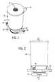
- FIG. 1is a perspective view of an oil mist removal device in accordance with the invention.
- FIG. 2is a side elevation view of the device of FIG. 1 .
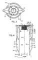
- FIG. 3is a bottom elevation view of the device of FIG. 2 .
- FIG. 4is a sectional view taken along line 4 - 4 of FIG. 2 .
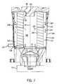
- FIG. 5is a perspective view of another embodiment of an oil mist removal device in accordance with the invention.
- FIG. 6is a top elevation view of the device of FIG. 5 .
- FIG. 7is a sectional view taken along line 7 - 7 of FIG. 6 .
- FIG. 1shows an oil mist removal device 10 , with integral oil fill 12 , for an internal combustion engine, schematically shown at 14 , FIGS. 2 , 4 .
- Device 10includes a housing 16 mounted to engine 14 , for example bolted to the engine valve cover through bolt holes such as 18 , 20 through housing bushing or flange 22 .
- Housing 16receives oil mist from the engine, as shown at arrows 24 , FIG. 4 .
- the housinghas a first passage 26 extending upwardly from the engine for receiving the oil mist.
- the housinghas a second passage 28 having an oil drain outlet 30 draining oil therefrom, and a gas outlet 32 discharging gas therefrom.
- the housinghas a flow path therethrough from engine 14 then through first passage 26 as shown at arrows 24 , 34 , then through second passage 28 as shown at arrows 36 , 38 , 40 .
- a separator 42is provided in the housing along the noted flow path between the first and second passages and separates the oil mist into separated oil, e.g. 38 , and gas, e.g. 40 .
- An oil fill port 12 in first passage 26is provided for adding oil to the engine.
- First passage 26has a lower inlet 44 receiving oil mist 24 from engine 14 , and has an upper port at 12 providing the noted oil fill port.
- An oil fill cap(not shown in FIGS. 1-4 , but shown at 46 in FIGS. 5-7 ) is removably mounted to the housing in sealing relation at oil fill port 12 , e.g. preferably in threaded relation.
- Oil fill cap 46has a first condition mounted to the housing in sealing relation at oil fill port 12 and blocking flow of oil mist 24 therepast from first passage 26 .
- Oil fill cap 46has a second condition removed from the housing and permitting oil to be introduced through the then open oil fill port 12 to flow through first passage 26 and through lower inlet port 44 to be added to engine 14 .
- Second passage 28has a first lower portion 48 passing separated oil downwardly to oil drain outlet 30 , and has a second portion 50 passing separated gas upwardly to gas outlet 32 .
- Second passage 28circumscribes first passage 26 .
- Housing 16extends along an axis 52 .
- First passage 26extends axially upwardly from oil mist inlet 44 to oil fill port 12 .
- First portion 48 of second passage 28extends axially downwardly to oil drain outlet 30 .
- Second portion 50 of second passage 28extends axially upwardly to gas outlet 32 .
- First and second passages 26 and 28are laterally offset from each other relative to axis 52 .
- the noted flow pathextends laterally as shown at 54 between first and second passages 26 and 28 .
- Housing 16has a first wall 56 extending axially along and defining first and second passages 26 and 28 on opposite lateral sides thereof. Housing 16 has a second wall 58 laterally spaced from first wall 56 and defining second passage 28 therebetween. Housing 16 has a baffle 60 laterally spaced between first and second walls 56 and 58 and extending axially downwardly in second passage 28 to a lower tip 62 . Second passage 28 has a lower portion at 48 below lower tip 62 , and has an upper portion at 50 above lower tip 62 . Upper portion 50 has a first subportion 64 laterally between first wall 56 and baffle 60 . Upper portion 50 has a second subportion 66 laterally between baffle 60 and second wall 58 .
- Both separated oil and separated gasflow axially downwardly in first subportion 64 of upper portion 50 of second passage 28 , as shown at arrow 36 .
- Separated gasflows axially upwardly in second subportion 66 of upper portion 50 of second passage 28 , as shown at arrow 40 .
- Separated oilflows axially downwardly in lower portion 48 of second passage 28 , as shown at arrow 38 .
- Housing 16has a wall 68 , FIG. 4 , at the top of first passage 26 and defining a mounting seat at 12 mounting an oil fill cap such as 46 .
- the housingmay include a second baffle (not shown in FIGS. 1-4 , but shown at 70 in FIG. 7 , providing an inlet baffle at oil mist inlet 44 directing oil mist flow from engine 14 into first passage 26 .
- separator 42is an impactor comprising a plurality of circumferentially spaced nozzles, e.g. openings, accelerating oil mist flow therethrough from first passage 26 against an impaction separation plate 74 .
- Nozzles 72accelerate the oil mist flow axially upwardly therethrough against a laterally extending impaction separation plate 74 axially spaced thereabove, whereafter separated oil and gas flow laterally at 54 to second passage 28 as shown at arrow 36 .
- FIGS. 5-7show an alternate embodiment and use like reference numerals from above where appropriate to facilitate understanding.
- FIGS. 5-7show an oil mist removal device 100 , with integral oil fill 102 , for internal combustion engine 14 .
- the deviceincludes a housing 104 mounted to engine 14 , for example bolted to the engine valve cover at bolt holes 106 , 108 through a mounting a flange or bushing 110 .
- the housingreceives oil mist from the engine as shown at 24 .
- Housing 104has a first passage 112 extending upwardly from the engine for receiving the oil mist at 24 .
- the housinghas a second passage 114 adjacent first passage 112 .
- Second passage 114has an oil drain outlet 116 draining oil therefrom, and has a gas outlet discharge 118 discharging gas therefrom.
- the housinghas a flow path therethrough from engine 14 then through first passage 112 as shown at arrows 24 , 120 , then through second passage 114 as shown at arrows 122 , 124 .
- a separator 126is provided in the housing along the noted flow path between first and second passages 112 and 114 and separates the oil mist into separated oil and gas as shown at arrows 122 and 124 respectively.
- An oil fill portis provided at 102 in first passage 112 for adding oil to the engine.
- First passage 112has a lower inlet port 128 providing an oil mist inlet receiving oil mist at 24 from engine 14 .
- First passage 112has an upper port at 102 providing the noted oil fill port.
- Oil fill cap 46is removably mounted to housing 104 in sealing relation at oil fill port 102 , preferably by being threaded thereto.
- Oil fill cap 46has a first condition mounted to housing 104 in sealing relation at oil fill port 102 and blocking flow of oil mist therepast from first passage 112 .
- Oil fill cap 46has a second condition removed from housing 104 and permitting oil to be introduced through the now open oil fill port 102 to flow through first passage 112 and through lower inlet port 128 to be added to the engine.
- Second passage 114has a first portion 130 passing separated oil downwardly to oil drain outlet 116 , as shown at arrow 122 .
- Second passage 114has a second portion 132 passing separated gas upwardly to gas outlet 118 , as shown at arrow 124 .
- Second passage 114circumscribes first passage 112 .
- Housing 104extends along axis 52 .
- First passage 112extends axially upwardly from oil mist inlet 128 to oil fill port 102 .
- First portion 130 of second passage 114extends axially downwardly to oil drain outlet 116 .
- Second portion 132 of second passage 114extends axially upwardly to gas outlet 118 .
- First and second passages 112 and 114are laterally offset from each other relative to axis 52 .
- the noted flow pathextends laterally as shown at 120 between first and second passages 112 and 114 .
- separator 126is a coalescer filter extending axially along and defining first and second passages 112 and 114 on opposite lateral sides thereof.
- Housing 104has a wall 134 laterally spaced from coalescer 126 and defining second passage 114 therebetween.
- Second passage 114has the noted lower portion at 130 and the noted upper portion at 132 . Separated oil flows axially downwardly in lower portion 130 of second passage 114 . Separated gas flows axially upwardly in upper portion 132 of second passage 114 .
- Housing 104has a mounting wall 136 , FIG. 7 , at the top of first passage 112 and defining a mounting seat mounting oil fill cap 46 .
- An inlet baffle 70is provided at oil mist inlet 128 directing oil mist flow at 24 from engine 14 into first passage 112 .
Landscapes
- Engineering & Computer Science (AREA)
- Mechanical Engineering (AREA)
- General Engineering & Computer Science (AREA)
- Lubrication Details And Ventilation Of Internal Combustion Engines (AREA)
Abstract
Description
Claims (6)
Priority Applications (1)
| Application Number | Priority Date | Filing Date | Title |
|---|---|---|---|
| US12/177,471US7810477B2 (en) | 2004-12-10 | 2008-07-22 | Oil mist removal device with oil fill |
Applications Claiming Priority (3)
| Application Number | Priority Date | Filing Date | Title |
|---|---|---|---|
| US63536404P | 2004-12-10 | 2004-12-10 | |
| US11/256,538US7406960B2 (en) | 2004-12-10 | 2005-10-21 | Oil mist removal device with oil fill |
| US12/177,471US7810477B2 (en) | 2004-12-10 | 2008-07-22 | Oil mist removal device with oil fill |
Related Parent Applications (1)
| Application Number | Title | Priority Date | Filing Date |
|---|---|---|---|
| US11/256,538DivisionUS7406960B2 (en) | 2004-09-21 | 2005-10-21 | Oil mist removal device with oil fill |
Publications (2)
| Publication Number | Publication Date |
|---|---|
| US20080276580A1 US20080276580A1 (en) | 2008-11-13 |
| US7810477B2true US7810477B2 (en) | 2010-10-12 |
Family
ID=36500390
Family Applications (2)
| Application Number | Title | Priority Date | Filing Date |
|---|---|---|---|
| US11/256,538Active2026-04-01US7406960B2 (en) | 2004-09-21 | 2005-10-21 | Oil mist removal device with oil fill |
| US12/177,471Active2026-05-05US7810477B2 (en) | 2004-12-10 | 2008-07-22 | Oil mist removal device with oil fill |
Family Applications Before (1)
| Application Number | Title | Priority Date | Filing Date |
|---|---|---|---|
| US11/256,538Active2026-04-01US7406960B2 (en) | 2004-09-21 | 2005-10-21 | Oil mist removal device with oil fill |
Country Status (2)
| Country | Link |
|---|---|
| US (2) | US7406960B2 (en) |
| DE (1) | DE102005059014B4 (en) |
Cited By (2)
| Publication number | Priority date | Publication date | Assignee | Title |
|---|---|---|---|---|
| US20100213144A1 (en)* | 2008-03-13 | 2010-08-26 | Unipure Energy, Corp. | Nozzle assembly for separating hydrocarbon emulsions and methods of separating hydrocarbon emulsions |
| US20110167774A1 (en)* | 2010-01-11 | 2011-07-14 | Cummins Filtration Ip Inc. | Drain Tube for Gas-Liquid Separation Systems |
Families Citing this family (25)
| Publication number | Priority date | Publication date | Assignee | Title |
|---|---|---|---|---|
| US20080072883A1 (en)* | 2004-07-06 | 2008-03-27 | Brancato David M | Motorcycle crankcase ventilation reservoir and dissipator |
| USD633924S1 (en)* | 2004-07-06 | 2011-03-08 | Brancato David M | Motorcycle crankcase ventilation reservoir and dissipater |
| US7406960B2 (en)* | 2004-12-10 | 2008-08-05 | Fleetguard, Inc. | Oil mist removal device with oil fill |
| US7964009B2 (en)* | 2004-09-21 | 2011-06-21 | Cummins Filtration Ip, Inc. | Inertial gas-liquid separator with axially variable orifice area |
| US7828865B2 (en) | 2008-07-31 | 2010-11-09 | Cummins Filtration Ip, Inc. | Gas-liquid separator with dual flow impaction and coalescence |
| US7614390B2 (en)* | 2007-08-23 | 2009-11-10 | Cummins Filtration Ip Inc. | Two stage drainage gas-liquid separator |
| US8075654B2 (en)* | 2004-09-21 | 2011-12-13 | Cummins Filtration Ip, Inc. | Gas-liquid separator with expansion transition flow |
| US7582130B2 (en)* | 2006-04-14 | 2009-09-01 | Cummins Filtration Ip Inc. | Coalescing filter assembly |
| US7959714B2 (en) | 2007-11-15 | 2011-06-14 | Cummins Filtration Ip, Inc. | Authorized filter servicing and replacement |
| US7678169B1 (en)* | 2006-07-12 | 2010-03-16 | Cummins Filtration Ip Inc. | Oil fill cap with air/oil separator |
| US7849841B2 (en)* | 2007-07-26 | 2010-12-14 | Cummins Filtration Ip, Inc. | Crankcase ventilation system with engine driven pumped scavenged oil |
| US7699029B2 (en) | 2007-07-26 | 2010-04-20 | Cummins Filtration Ip, Inc. | Crankcase ventilation system with pumped scavenged oil |
| US7776139B2 (en)* | 2008-02-06 | 2010-08-17 | Cummins Filtration Ip, Inc. | Separator with transfer tube drainage |
| US8146545B2 (en)* | 2008-02-25 | 2012-04-03 | Parker-Hannifin Corporation | Filter for a crankcase ventilation system |
| US8360251B2 (en) | 2008-10-08 | 2013-01-29 | Cummins Filtration Ip, Inc. | Multi-layer coalescing media having a high porosity interior layer and uses thereof |
| US8146574B2 (en)* | 2009-02-11 | 2012-04-03 | Cummins Filtration Ip, Inc. | Engine air management system |
| CN105477903B (en) | 2009-05-15 | 2017-12-12 | 康明斯过滤Ip公司 | Surface coalescer |
| US10279294B2 (en)* | 2011-06-01 | 2019-05-07 | Agilent Technologies, Inc. | Self cleaning gas-liquid separator for serial or parallel collection of liquid fractions |
| DE102011105482A1 (en)* | 2011-06-24 | 2012-12-27 | Hydac Filtertechnik Gmbh | separating |
| WO2014022386A2 (en) | 2012-07-31 | 2014-02-06 | Cummins Filtration Ip, Inc. | Methods and apparatuses for separating liquid particles from a gas-liquid stream |
| US10058808B2 (en) | 2012-10-22 | 2018-08-28 | Cummins Filtration Ip, Inc. | Composite filter media utilizing bicomponent fibers |
| US9873325B1 (en)* | 2014-10-22 | 2018-01-23 | Hydro-Gear Limited Partnership | Drive apparatus |
| DE112017002974T5 (en) | 2016-07-19 | 2019-03-07 | Cummins Filtration Ip, Inc. | KOALESZER WITH PERFORATED LAYER |
| CN115435229B (en)* | 2022-08-24 | 2024-01-12 | 北京磐基机电设备有限公司 | Heavy pressure accumulating float valve type automatic oil drain device |
| US12071871B1 (en)* | 2023-06-12 | 2024-08-27 | Caterpillar Inc. | Positive pressure air cleaning apparatus for a crankcase ventilation system |
Citations (60)
| Publication number | Priority date | Publication date | Assignee | Title |
|---|---|---|---|---|
| US1548288A (en) | 1921-12-19 | 1925-08-04 | Gas Res Co | Gas purification |
| CH127029A (en) | 1927-05-17 | 1928-08-16 | Henri Haegler | Purifier for gaseous fluids loaded with suspended impurities. |
| US1761944A (en) | 1930-06-03 | A oobpobamof osi deiiawabb | ||
| US2493617A (en) | 1946-03-07 | 1950-01-03 | Ford Motor Co | Oil separator for crankcase vapors |
| FR1406047A (en) | 1964-06-05 | 1965-07-16 | Alcatel Sa | Method and device for stopping mists in gas streams |
| US3201925A (en) | 1961-08-17 | 1965-08-24 | Int Basic Economy Corp | Variable flow separator |
| US3433231A (en) | 1966-12-05 | 1969-03-18 | Frank Siragusa | Filter |
| US3923480A (en) | 1972-04-19 | 1975-12-02 | Holima Bv James H | Oil separator |
| US4012209A (en) | 1976-04-05 | 1977-03-15 | The United States Of America As Represented By The United States Energy Research And Development Administration | Liquid film target impingement scrubber |
| US4014673A (en) | 1976-02-02 | 1977-03-29 | Kinnison Daniel E | Air precleaner |
| US4401093A (en) | 1982-06-09 | 1983-08-30 | Ford Motor Company | Oil fill/air breather cap with integral oil separator |
| US4993517A (en) | 1989-05-05 | 1991-02-19 | Filterwerk Mann & Hummel Gmbh | Oil-fill opening for introducing lubricating oil into an internal combustion engine |
| US5129371A (en) | 1991-09-03 | 1992-07-14 | Saturn Corporation | Cam cover oil separator for crankcase ventilation |
| US5201301A (en) | 1992-05-28 | 1993-04-13 | Re-Tech, Inc. | Adjustable ambient air filtering system and pollution control device |
| US5205848A (en) | 1991-03-29 | 1993-04-27 | Pall France Services | Device ensuring filtration and communication between the atmosphere and the inside of a crankcase |
| US5329913A (en) | 1991-03-26 | 1994-07-19 | Yamaha Hatsudoki Kabushiki Kaisha | Oil vapor separator system for the engine of a gas heat pump air conditioner |
| US5460147A (en) | 1993-12-24 | 1995-10-24 | Knecht Filterwerke Gmbh | Cyclone separator for an internal combustion engine |
| US5562087A (en) | 1995-10-17 | 1996-10-08 | Wright; Richard T. | Oil separator for blow-by gases |
| US5564401A (en) | 1995-07-21 | 1996-10-15 | Diesel Research Inc. | Crankcase emission control system |
| US6074448A (en) | 1997-04-10 | 2000-06-13 | Thomas Josef Heimbach Gesellschaft Mit Beschrankter Haftung & Co. | Device for use in filtering separators |
| US6073618A (en) | 1998-12-02 | 2000-06-13 | Chrysler Corporation | Engine oil fill assembly with integral funnel and oil separator |
| US6152120A (en) | 1999-06-04 | 2000-11-28 | Caterpillar Inc. | Diesel engine system with oil-air separator and method of operation |
| EP1068890A1 (en) | 1999-07-16 | 2001-01-17 | Nelson Industries, Inc. | Inertial gas-liquid separator |
| US6247463B1 (en) | 1999-09-01 | 2001-06-19 | Nelson Industries, Inc. | Diesel engine crankcase ventilation filter |
| US6279556B1 (en) | 1999-03-18 | 2001-08-28 | Walter Hengst Gmbh & Co., Kg | Oil separator for removing oil from the crankcase ventilation gases of an internal combustion engine |
| US6293268B1 (en) | 1999-10-07 | 2001-09-25 | Siemens Automotive, Inc. | Positive crankcase ventilation system |
| US6354283B1 (en) | 2000-08-29 | 2002-03-12 | Fleetguard, Inc. | Diesel engine modular crankcase ventilation filter |
| DE10051307A1 (en) | 2000-10-17 | 2002-05-02 | Bosch Gmbh Robert | Device for separating gas and liquid-solid particles from a gas-liquid-solid particle mixture flowing in a line and method for separating the same |
| US6402798B1 (en) | 2000-09-19 | 2002-06-11 | Nelson Industries, Inc. | Twist and lock filter housing with nontorsional anti-rotation stop |
| US6435170B1 (en)* | 2001-08-01 | 2002-08-20 | Dana Corporation | Crankcase bypass system with oil scavenging device |
| US6478018B2 (en) | 1999-09-01 | 2002-11-12 | Nelson Industries, Inc. | Multi-peripheral perimeter sealed flat panel coalescing filter element |
| US6478019B2 (en) | 1999-09-01 | 2002-11-12 | Nelson Industries, Inc. | Flat low profile diesel engine crankcase ventilation filter |
| US6505615B2 (en) | 2000-05-30 | 2003-01-14 | Ing. Walter Hengst Gmbh & Co. Kg | Device to deoil the crankcase ventilation gases of an internal combustion engine |
| US6533712B1 (en) | 2000-10-17 | 2003-03-18 | Fleetguard, Inc. | Centrifuge housing with oil fill port |
| US6568540B1 (en) | 2000-12-13 | 2003-05-27 | Nelson Industries, Inc. | Low force closure filter with integral seal |
| US6576045B2 (en) | 2001-09-10 | 2003-06-10 | Fleetguard, Inc. | Multi-stage diesel particulate collector system with combined processes of inertial impaction, virtual impaction, and filtration |
| US6601385B2 (en) | 2001-10-17 | 2003-08-05 | Fleetguard, Inc. | Impactor for selective catalytic reduction system |
| FR2835764A1 (en) | 2002-02-14 | 2003-08-15 | Mann & Hummel Filter | Cyclone separators operating in parallel at high efficiency, have inlet openings which can be opened or closed individually |
| US6626163B1 (en) | 1999-05-06 | 2003-09-30 | Walter Hengst Gmbh & Co. Kg | Oil separator for de-oiling crankcase ventilation gases of an internal combustion engine |
| US6684864B1 (en) | 1999-04-22 | 2004-02-03 | Ing. Walter Hengst Gmbh & Co. Gmbh | Method for removing oil from crankcase ventilation gases and devices for implementing said method |
| FR2852056A1 (en) | 2003-03-04 | 2004-09-10 | Bosch Gmbh Robert | Liquid separating device for internal combustion device, has crankcase with separator units and distribution channel to receive sealing unit in mobile manner, where sealing unit is regulated based on crankcase pressure |
| EP1477641A1 (en) | 2003-05-15 | 2004-11-17 | Robert Bosch Gmbh | Device for separating fluids from a gas stream |
| DE10320215A1 (en) | 2003-05-05 | 2004-12-09 | Dichtungstechnik G. Bruss Gmbh & Co. Kg | Oil separation unit for blow by gas of an internal combustion engine comprises a separator element with at least one passage in the form of a long narrow gap whose width is alterable |
| US20050000572A1 (en) | 2003-06-24 | 2005-01-06 | Morten Muller Ltd. Aps | Device for splitting a two-phase stream into two or more streams with the desired vapor/liquid ratios |
| US6973925B2 (en) | 2000-09-09 | 2005-12-13 | Mahle Filtersysteme Gmbh | Ventilation device for crankcase |
| US20060062699A1 (en) | 2004-09-21 | 2006-03-23 | Evenstad Karl G | Inertial gas-liquid separator with variable flow actuator |
| US20060059875A1 (en) | 2004-09-21 | 2006-03-23 | Gerard Malgorn | Variable flow inertial gas-liquid impactor separator |
| US20060081229A1 (en) | 2004-10-19 | 2006-04-20 | Gronberg Philip F | Combined filter and fill tube |
| US7080636B2 (en) | 2003-05-05 | 2006-07-25 | Dichtungstechnik G. Bruss Gmbh & Co. Kg | Oil separating device for a combustion engine |
| US20060249128A1 (en) | 2005-05-06 | 2006-11-09 | Teng-Hua Shieh | Oil separator |
| WO2006119737A1 (en) | 2005-05-10 | 2006-11-16 | Mahle International Gmbh | Centrifugal oil mist separation device integrated in an axial hollow shaft of an internal combustion engine |
| US7152589B2 (en) | 2002-06-20 | 2006-12-26 | Alfa Laval Corporate Ab | Method and a device for cleaning of crankcase gas |
| US7156901B2 (en) | 2001-11-01 | 2007-01-02 | Alfa Laval Corporate Ab | Apparatus for simultaneous cleaning of a liquid and a gas |
| WO2007028351A1 (en) | 2005-09-06 | 2007-03-15 | Mahle International Gmbh | Device for separating a gas-liquid mixture |
| US20070062887A1 (en) | 2005-09-20 | 2007-03-22 | Schwandt Brian W | Space optimized coalescer |
| US20070256566A1 (en) | 2004-09-21 | 2007-11-08 | Faber Stephanie L | Multistage Variable Impactor |
| WO2007137934A2 (en) | 2006-05-29 | 2007-12-06 | Mahle International Gmbh | Device for ventilating a crankcase |
| WO2007138008A2 (en) | 2006-05-29 | 2007-12-06 | Mahle International Gmbh | Device for separating a gas-liquid mixture, in particular during ventilation of a crankcase of an internal combustion engine |
| US7406960B2 (en) | 2004-12-10 | 2008-08-05 | Fleetguard, Inc. | Oil mist removal device with oil fill |
| US7678169B1 (en)* | 2006-07-12 | 2010-03-16 | Cummins Filtration Ip Inc. | Oil fill cap with air/oil separator |
Family Cites Families (4)
| Publication number | Priority date | Publication date | Assignee | Title |
|---|---|---|---|---|
| DE2838395C2 (en)* | 1978-09-02 | 1980-03-13 | Voith-Turbo Gmbh & Co Kg, 7180 Crailsheim | Ventilation device for the housing interior of a rotary machine |
| DE19912855A1 (en)* | 1999-03-22 | 2000-09-28 | Elenac Gmbh | Process for the production of ethylene copolymer |
| US6161529A (en)* | 1999-06-10 | 2000-12-19 | Parker-Hannifin Corporation | Filter assembly with sump and check valve |
| DE19948163A1 (en)* | 1999-10-07 | 2001-04-12 | Volkswagen Ag | Device for venting a crankcase/cylinder head in an internal combustion engine includes a feeder device for a mixture of gas, steam and mist coming from the crankcase and/or cylinder head in an internal combustion engine. |
- 2005
- 2005-10-21USUS11/256,538patent/US7406960B2/enactiveActive
- 2005-12-08DEDE102005059014.4Apatent/DE102005059014B4/ennot_activeExpired - Fee Related
- 2008
- 2008-07-22USUS12/177,471patent/US7810477B2/enactiveActive
Patent Citations (69)
| Publication number | Priority date | Publication date | Assignee | Title |
|---|---|---|---|---|
| US1761944A (en) | 1930-06-03 | A oobpobamof osi deiiawabb | ||
| US1548288A (en) | 1921-12-19 | 1925-08-04 | Gas Res Co | Gas purification |
| CH127029A (en) | 1927-05-17 | 1928-08-16 | Henri Haegler | Purifier for gaseous fluids loaded with suspended impurities. |
| US2493617A (en) | 1946-03-07 | 1950-01-03 | Ford Motor Co | Oil separator for crankcase vapors |
| US3201925A (en) | 1961-08-17 | 1965-08-24 | Int Basic Economy Corp | Variable flow separator |
| FR1406047A (en) | 1964-06-05 | 1965-07-16 | Alcatel Sa | Method and device for stopping mists in gas streams |
| DE1544126A1 (en) | 1964-06-05 | 1969-06-12 | Alcatel Sa | Method and device for holding back the mist in gas flows |
| US3433231A (en) | 1966-12-05 | 1969-03-18 | Frank Siragusa | Filter |
| US3923480A (en) | 1972-04-19 | 1975-12-02 | Holima Bv James H | Oil separator |
| US4014673A (en) | 1976-02-02 | 1977-03-29 | Kinnison Daniel E | Air precleaner |
| US4012209A (en) | 1976-04-05 | 1977-03-15 | The United States Of America As Represented By The United States Energy Research And Development Administration | Liquid film target impingement scrubber |
| US4401093A (en) | 1982-06-09 | 1983-08-30 | Ford Motor Company | Oil fill/air breather cap with integral oil separator |
| US4993517A (en) | 1989-05-05 | 1991-02-19 | Filterwerk Mann & Hummel Gmbh | Oil-fill opening for introducing lubricating oil into an internal combustion engine |
| US5329913A (en) | 1991-03-26 | 1994-07-19 | Yamaha Hatsudoki Kabushiki Kaisha | Oil vapor separator system for the engine of a gas heat pump air conditioner |
| US5205848A (en) | 1991-03-29 | 1993-04-27 | Pall France Services | Device ensuring filtration and communication between the atmosphere and the inside of a crankcase |
| US5129371A (en) | 1991-09-03 | 1992-07-14 | Saturn Corporation | Cam cover oil separator for crankcase ventilation |
| US5201301A (en) | 1992-05-28 | 1993-04-13 | Re-Tech, Inc. | Adjustable ambient air filtering system and pollution control device |
| US5460147A (en) | 1993-12-24 | 1995-10-24 | Knecht Filterwerke Gmbh | Cyclone separator for an internal combustion engine |
| US5564401A (en) | 1995-07-21 | 1996-10-15 | Diesel Research Inc. | Crankcase emission control system |
| EP0754840A1 (en) | 1995-07-21 | 1997-01-22 | Diesel Research Inc. | Crankcase emission control system |
| US5562087A (en) | 1995-10-17 | 1996-10-08 | Wright; Richard T. | Oil separator for blow-by gases |
| US6074448A (en) | 1997-04-10 | 2000-06-13 | Thomas Josef Heimbach Gesellschaft Mit Beschrankter Haftung & Co. | Device for use in filtering separators |
| US6073618A (en) | 1998-12-02 | 2000-06-13 | Chrysler Corporation | Engine oil fill assembly with integral funnel and oil separator |
| US6279556B1 (en) | 1999-03-18 | 2001-08-28 | Walter Hengst Gmbh & Co., Kg | Oil separator for removing oil from the crankcase ventilation gases of an internal combustion engine |
| US6684864B1 (en) | 1999-04-22 | 2004-02-03 | Ing. Walter Hengst Gmbh & Co. Gmbh | Method for removing oil from crankcase ventilation gases and devices for implementing said method |
| US6626163B1 (en) | 1999-05-06 | 2003-09-30 | Walter Hengst Gmbh & Co. Kg | Oil separator for de-oiling crankcase ventilation gases of an internal combustion engine |
| US6152120A (en) | 1999-06-04 | 2000-11-28 | Caterpillar Inc. | Diesel engine system with oil-air separator and method of operation |
| EP1068890A1 (en) | 1999-07-16 | 2001-01-17 | Nelson Industries, Inc. | Inertial gas-liquid separator |
| US6290738B1 (en) | 1999-07-16 | 2001-09-18 | Nelson Industries, Inc. | Inertial gas-liquid separator having an inertial collector spaced from a nozzle structure |
| US6478019B2 (en) | 1999-09-01 | 2002-11-12 | Nelson Industries, Inc. | Flat low profile diesel engine crankcase ventilation filter |
| US6478018B2 (en) | 1999-09-01 | 2002-11-12 | Nelson Industries, Inc. | Multi-peripheral perimeter sealed flat panel coalescing filter element |
| US6247463B1 (en) | 1999-09-01 | 2001-06-19 | Nelson Industries, Inc. | Diesel engine crankcase ventilation filter |
| US6293268B1 (en) | 1999-10-07 | 2001-09-25 | Siemens Automotive, Inc. | Positive crankcase ventilation system |
| US6418918B2 (en) | 1999-10-07 | 2002-07-16 | Siemens Canada Limited | Positive crankcase ventilation system |
| US6505615B2 (en) | 2000-05-30 | 2003-01-14 | Ing. Walter Hengst Gmbh & Co. Kg | Device to deoil the crankcase ventilation gases of an internal combustion engine |
| US6354283B1 (en) | 2000-08-29 | 2002-03-12 | Fleetguard, Inc. | Diesel engine modular crankcase ventilation filter |
| US6973925B2 (en) | 2000-09-09 | 2005-12-13 | Mahle Filtersysteme Gmbh | Ventilation device for crankcase |
| US6402798B1 (en) | 2000-09-19 | 2002-06-11 | Nelson Industries, Inc. | Twist and lock filter housing with nontorsional anti-rotation stop |
| US6797040B2 (en) | 2000-10-17 | 2004-09-28 | Robert Bosch Gmbh | Device for the separation of gas and liquid/solid particles in a mixture of gas and fluid/solid particles flowing in a line and method for the separation thereof |
| US6533712B1 (en) | 2000-10-17 | 2003-03-18 | Fleetguard, Inc. | Centrifuge housing with oil fill port |
| DE10051307A1 (en) | 2000-10-17 | 2002-05-02 | Bosch Gmbh Robert | Device for separating gas and liquid-solid particles from a gas-liquid-solid particle mixture flowing in a line and method for separating the same |
| US6568540B1 (en) | 2000-12-13 | 2003-05-27 | Nelson Industries, Inc. | Low force closure filter with integral seal |
| US6435170B1 (en)* | 2001-08-01 | 2002-08-20 | Dana Corporation | Crankcase bypass system with oil scavenging device |
| US6576045B2 (en) | 2001-09-10 | 2003-06-10 | Fleetguard, Inc. | Multi-stage diesel particulate collector system with combined processes of inertial impaction, virtual impaction, and filtration |
| US6601385B2 (en) | 2001-10-17 | 2003-08-05 | Fleetguard, Inc. | Impactor for selective catalytic reduction system |
| US7156901B2 (en) | 2001-11-01 | 2007-01-02 | Alfa Laval Corporate Ab | Apparatus for simultaneous cleaning of a liquid and a gas |
| FR2835764A1 (en) | 2002-02-14 | 2003-08-15 | Mann & Hummel Filter | Cyclone separators operating in parallel at high efficiency, have inlet openings which can be opened or closed individually |
| US7152589B2 (en) | 2002-06-20 | 2006-12-26 | Alfa Laval Corporate Ab | Method and a device for cleaning of crankcase gas |
| FR2852056A1 (en) | 2003-03-04 | 2004-09-10 | Bosch Gmbh Robert | Liquid separating device for internal combustion device, has crankcase with separator units and distribution channel to receive sealing unit in mobile manner, where sealing unit is regulated based on crankcase pressure |
| US7080636B2 (en) | 2003-05-05 | 2006-07-25 | Dichtungstechnik G. Bruss Gmbh & Co. Kg | Oil separating device for a combustion engine |
| DE10320215A1 (en) | 2003-05-05 | 2004-12-09 | Dichtungstechnik G. Bruss Gmbh & Co. Kg | Oil separation unit for blow by gas of an internal combustion engine comprises a separator element with at least one passage in the form of a long narrow gap whose width is alterable |
| EP1477641A1 (en) | 2003-05-15 | 2004-11-17 | Robert Bosch Gmbh | Device for separating fluids from a gas stream |
| US20050000572A1 (en) | 2003-06-24 | 2005-01-06 | Morten Muller Ltd. Aps | Device for splitting a two-phase stream into two or more streams with the desired vapor/liquid ratios |
| US20060059875A1 (en) | 2004-09-21 | 2006-03-23 | Gerard Malgorn | Variable flow inertial gas-liquid impactor separator |
| US7238216B2 (en) | 2004-09-21 | 2007-07-03 | Cummins Filtration Ip, Inc. | Variable flow inertial gas-liquid impactor separator |
| US20060062699A1 (en) | 2004-09-21 | 2006-03-23 | Evenstad Karl G | Inertial gas-liquid separator with variable flow actuator |
| US20070256566A1 (en) | 2004-09-21 | 2007-11-08 | Faber Stephanie L | Multistage Variable Impactor |
| US20060081229A1 (en) | 2004-10-19 | 2006-04-20 | Gronberg Philip F | Combined filter and fill tube |
| US7185643B2 (en) | 2004-10-19 | 2007-03-06 | International Engine Intellectual Property Company, Llc | Combined filter and fill tube |
| US7406960B2 (en) | 2004-12-10 | 2008-08-05 | Fleetguard, Inc. | Oil mist removal device with oil fill |
| US7258111B2 (en)* | 2005-05-06 | 2007-08-21 | Toyota Motor Engineering & Manufacturing North America, Inc. | Oil separator |
| US20060249128A1 (en) | 2005-05-06 | 2006-11-09 | Teng-Hua Shieh | Oil separator |
| WO2006119737A1 (en) | 2005-05-10 | 2006-11-16 | Mahle International Gmbh | Centrifugal oil mist separation device integrated in an axial hollow shaft of an internal combustion engine |
| DE102005042286A1 (en) | 2005-09-06 | 2007-04-12 | Mahle International Gmbh | Device for separating a gas-liquid mixture |
| WO2007028351A1 (en) | 2005-09-06 | 2007-03-15 | Mahle International Gmbh | Device for separating a gas-liquid mixture |
| US20070062887A1 (en) | 2005-09-20 | 2007-03-22 | Schwandt Brian W | Space optimized coalescer |
| WO2007137934A2 (en) | 2006-05-29 | 2007-12-06 | Mahle International Gmbh | Device for ventilating a crankcase |
| WO2007138008A2 (en) | 2006-05-29 | 2007-12-06 | Mahle International Gmbh | Device for separating a gas-liquid mixture, in particular during ventilation of a crankcase of an internal combustion engine |
| US7678169B1 (en)* | 2006-07-12 | 2010-03-16 | Cummins Filtration Ip Inc. | Oil fill cap with air/oil separator |
Non-Patent Citations (1)
| Title |
|---|
| Highly Efficient Oil Separation Systems for Minimised Oil Carry Over, MTZ Apr. 2008, vol. 69, pp. 32-37. |
Cited By (5)
| Publication number | Priority date | Publication date | Assignee | Title |
|---|---|---|---|---|
| US20100213144A1 (en)* | 2008-03-13 | 2010-08-26 | Unipure Energy, Corp. | Nozzle assembly for separating hydrocarbon emulsions and methods of separating hydrocarbon emulsions |
| US8097058B2 (en)* | 2008-03-13 | 2012-01-17 | Britewater International, Llc | Nozzle assembly for separating hydrocarbon emulsions and methods of separating hydrocarbon emulsions |
| US20110167774A1 (en)* | 2010-01-11 | 2011-07-14 | Cummins Filtration Ip Inc. | Drain Tube for Gas-Liquid Separation Systems |
| DE112011100225T5 (en) | 2010-01-11 | 2012-12-06 | Cummins Filtration Ip, Inc. | Outlet pipe for gas-liquid separation systems |
| US8470062B2 (en) | 2010-01-11 | 2013-06-25 | Cummins Filtration Ip Inc. | Drain tube for gas-liquid separation systems |
Also Published As
| Publication number | Publication date |
|---|---|
| DE102005059014B4 (en) | 2016-02-25 |
| US20080276580A1 (en) | 2008-11-13 |
| DE102005059014A1 (en) | 2006-06-14 |
| US20060124117A1 (en) | 2006-06-15 |
| US7406960B2 (en) | 2008-08-05 |
Similar Documents
| Publication | Publication Date | Title |
|---|---|---|
| US7810477B2 (en) | Oil mist removal device with oil fill | |
| US7776139B2 (en) | Separator with transfer tube drainage | |
| US7614390B2 (en) | Two stage drainage gas-liquid separator | |
| EP1818520B1 (en) | Improved oil drain device for an engine oil separator | |
| US5450835A (en) | Oil separator for reducing oil losses from crankcase ventilation | |
| US4723529A (en) | Oil separator for a blowby gas ventilation system of an internal combustion engine | |
| JP2000045749A (en) | Oil separator for blow-by gas | |
| EP1887192B1 (en) | Vapor-liquid separator | |
| EP1229248B1 (en) | Compressor system | |
| US8256404B2 (en) | Oil separator for blow-by gas | |
| US20090159056A1 (en) | PCV System for V-Type Engine | |
| WO2015111345A1 (en) | Oil separator for blow-by gas | |
| WO2012157309A1 (en) | Oil separator for internal combustion engine | |
| US10661210B2 (en) | Oil separator including spiral members defining helical flow paths | |
| US5664549A (en) | Breather system for an internal combustion engine | |
| US8156926B2 (en) | Systems and methods for filtering crankcase fumes | |
| JP2010203299A (en) | Oil separator | |
| CN111075535B (en) | Splitter | |
| JPH08158853A (en) | Separator of oil in blow-by gas | |
| US20190178122A1 (en) | Oil Separators | |
| US20050092309A1 (en) | Blowby gas separation system | |
| JP2011032889A (en) | Oil separator for blow-by gas | |
| US7096847B1 (en) | Oil separator for internal combustion engine | |
| CN109944660B (en) | Oil separator including a scroll member defining a spiral flow path | |
| JP4110079B2 (en) | Internal combustion engine head cover |
Legal Events
| Date | Code | Title | Description |
|---|---|---|---|
| AS | Assignment | Owner name:CUMMINS FILTRATION IP, INC., MINNESOTA Free format text:ASSIGNMENT OF ASSIGNORS INTEREST;ASSIGNOR:FLEETGUARD, INC.;REEL/FRAME:021380/0305 Effective date:20080808 | |
| STCF | Information on status: patent grant | Free format text:PATENTED CASE | |
| FPAY | Fee payment | Year of fee payment:4 | |
| AS | Assignment | Owner name:CUMMINS FILTRATION INC., TENNESSEE Free format text:MERGER AND CHANGE OF NAME;ASSIGNORS:FLEETGUARD;CUMMINS FILTRATION INC.;REEL/FRAME:033065/0086 Effective date:20060524 | |
| MAFP | Maintenance fee payment | Free format text:PAYMENT OF MAINTENANCE FEE, 8TH YEAR, LARGE ENTITY (ORIGINAL EVENT CODE: M1552) Year of fee payment:8 | |
| MAFP | Maintenance fee payment | Free format text:PAYMENT OF MAINTENANCE FEE, 12TH YEAR, LARGE ENTITY (ORIGINAL EVENT CODE: M1553); ENTITY STATUS OF PATENT OWNER: LARGE ENTITY Year of fee payment:12 | |
| AS | Assignment | Owner name:BANK OF AMERICA, N.A., AS ADMINISTRATIVE AGENT, NORTH CAROLINA Free format text:SECURITY INTEREST;ASSIGNOR:CUMMINS FILTRATION INC;REEL/FRAME:063821/0518 Effective date:20230531 |