US7810330B1 - Power generation using thermal gradients maintained by phase transitions - Google Patents
Power generation using thermal gradients maintained by phase transitionsDownload PDFInfo
- Publication number
- US7810330B1 US7810330B1US11/467,819US46781906AUS7810330B1US 7810330 B1US7810330 B1US 7810330B1US 46781906 AUS46781906 AUS 46781906AUS 7810330 B1US7810330 B1US 7810330B1
- Authority
- US
- United States
- Prior art keywords
- heat
- transport medium
- phase transition
- ambient environment
- energy
- Prior art date
- Legal status (The legal status is an assumption and is not a legal conclusion. Google has not performed a legal analysis and makes no representation as to the accuracy of the status listed.)
- Expired - Fee Related, expires
Links
Images


Classifications
- F—MECHANICAL ENGINEERING; LIGHTING; HEATING; WEAPONS; BLASTING
- F01—MACHINES OR ENGINES IN GENERAL; ENGINE PLANTS IN GENERAL; STEAM ENGINES
- F01K—STEAM ENGINE PLANTS; STEAM ACCUMULATORS; ENGINE PLANTS NOT OTHERWISE PROVIDED FOR; ENGINES USING SPECIAL WORKING FLUIDS OR CYCLES
- F01K13/00—General layout or general methods of operation of complete plants
- F—MECHANICAL ENGINEERING; LIGHTING; HEATING; WEAPONS; BLASTING
- F01—MACHINES OR ENGINES IN GENERAL; ENGINE PLANTS IN GENERAL; STEAM ENGINES
- F01K—STEAM ENGINE PLANTS; STEAM ACCUMULATORS; ENGINE PLANTS NOT OTHERWISE PROVIDED FOR; ENGINES USING SPECIAL WORKING FLUIDS OR CYCLES
- F01K25/00—Plants or engines characterised by use of special working fluids, not otherwise provided for; Plants operating in closed cycles and not otherwise provided for
- F01K25/08—Plants or engines characterised by use of special working fluids, not otherwise provided for; Plants operating in closed cycles and not otherwise provided for using special vapours
- F01K25/10—Plants or engines characterised by use of special working fluids, not otherwise provided for; Plants operating in closed cycles and not otherwise provided for using special vapours the vapours being cold, e.g. ammonia, carbon dioxide, ether
Definitions
- This applicationrelates generally to power generation. More specifically, this application relates to the use of phase transitions to maintain thermal gradients in power generation.
- thermodynamic techniquesfor converting heat energy into mechanical, electrical, or some other type of energy has a long history.
- the basic principle by which such techniques functionis to provide a large temperature differential across a thermodynamic engine and to convert the heat represented by that temperature differential into a different form of energy.
- the heat differentialis provided by hydrocarbon combustion, although the use of other techniques is known.
- poweris typically generated with an efficiency of about 30%, although some internal-combustion engines have efficiencies as high as 50% by running at very high temperatures.
- Conversion of heat into mechanical energyis typically achieved using an engine like a Stirling engine, which implements a Carnot cycle to convert the thermal energy.
- the mechanical energymay subsequently be converted to electrical energy using any of a variety of known electromechanical systems.
- Thermoelectric systemsmay be used to convert heat into electrical energy directly, although thermoelectric systems are more commonly operated in the opposite direction by using electrical energy to generate a temperature differential in heating or cooling applications.
- Embodiments of the inventionprovide methods and systems for generating power from an ambient environment through the use of thermodynamic engines.
- a thermodynamic engineis disposed in an ambient environment. The thermodynamic engine is configured to convert heat provided in the form of a temperature differential to a nonheat form of energy.
- a heat-conduction assemblyis also provided in the ambient environment, the heat-conduction assembly comprising a heat-transport medium in thermal communication with the thermodynamic engine. Conditions in the ambient environment induce a phase transition in the heat-transport medium that causes the temperature differential with the ambient environment.
- the thermodynamic engineis run to convert heat energy from the temperature differential with the ambient environment into the nonheat form of energy.
- the heat-transport mediumis renewed by allowing the ambient environment to change conditions to induce a reverse phase transition in the heat-transport medium, permitting the heat-transport medium to repeatedly or continuously undergo the phase transition that causes the temperature differential with the ambient environment.
- thermodynamic enginesmay be used in different embodiments.
- the thermodynamic enginecomprises a Stirling engine and the nonheat form of energy comprises mechanical energy.
- the thermodynamic enginecomprises a thermoelectric engine and the nonheat form of energy comprises electrical energy.
- heat-transport medium lost in the phase transitionmay sometimes be replaced.
- a second heat-transport mediumis also provided in thermal communication with the thermodynamic engine so that a phase transition may be induced in the second heat-transport medium to enhance the temperature differential.
- a thermal contribution to the temperature differential from the phase transition in the second heat-transport mediummay be opposite in direction to a thermal contribution to the temperature differential from the phase transition in the second heat-transport medium.
- phase transitionis selected from the group consisting of a liquid-gas phase transition, a solid-liquid phase transition, and a solid-gas phase transition.
- phase transitioncomprises a transition between polymorphs and/or allotropes of the heat-transport medium. Examples of heat-transport media that may be used in different embodiments include water and cryogens.
- movement of the ambient environmentis induced to increase a rate of the phase transition.
- the efficiency of running the thermodynamic engine to convert heat from the ambient environment into the nonheat form of energymay sometimes be less than 10%.
- FIGS. 1A-1Dshow different stages in the operation of a two-piston Stirling engine
- FIG. 1Eis a phase diagram showing the thermodynamic operation of the Stirling engine
- FIGS. 2A-2Dshow different stages in the operation of a displacer-type Stirling engine
- FIGS. 3A and 3Bare schematics illustrating embodiments of the invention for using thermal gradients maintained by phase transitions in power generation
- FIG. 4is a flow diagram summarizing methods for generating power in various embodiments
- FIG. 5is a schematic illustration of the operation of a thermodynamic engine in an embodiment
- FIG. 6provides a schematic illustration of a first application of methods of the invention.
- FIG. 7provides a schematic illustration of a second application of methods of the invention.
- thermodynamic enginerefers to any device or system capable of converting thermal energy to a different form of energy.
- examples of thermodynamic enginesinclude engines like external and internal combustion engines that effect an energy conversion between mechanical energy and a temperature differential; and engines like thermoelectric, pyroelectric, and thermophotovoltaic engines that effect a conversion between electrical energy and a temperature differential.
- FIGS. 1A-1Eshow the configuration of the Stirling engine 100 at a different position during a single cycle, with the engine 100 operating by changing positions sequentially from FIG. 1A to FIG. 1D and then returning to the configuration shown in FIG. 1A .
- the phase diagram shown in FIG. 1Ealso shows this cycle, but from the perspective of relevant thermodynamic variables.
- the phase diagramis a pressure-volume diagram, with pressure being plotted on the ordinate and volume being plotted on the abscissa. Relevant isotherms 124 and 128 are shown with dotted lines.
- the mechanical energy produced by the Stirling engine 100is indicated by positions of pistons 112 and 116 .
- the pistons 112 and 116may be connected to a common shaft that rotates or otherwise moves in accordance with the changes in piston positions that result from operation of the engine 100 .
- a confined space between the two pistons 112 and 116is filled with a compressible fluid 104 , usually a compressible gas.
- the temperature differenceis effected by keeping one portion of the fluid 104 , in this instance the portion on the left, in thermal contact with a heat source and by keeping the other portion, in this instance the portion on the right, in thermal contact with a heat sink.
- piston 112is sometimes referred to in the art as an “expansion piston” and piston 116 is sometimes referred to as a “compression piston.”
- the portions of the fluidare separated by a regenerator 108 , which permits appreciable heat transfer to take place to and from the fluid 104 during different portions of the cycle described below. This heat transfer either preheats or precools the fluid 104 as it transitions from one chamber to the other.
- the fluid 104When the engine is in the position shown in FIG. 1A , the fluid 104 has a pressure and volume that correspond to point “A” in FIG. 1E .
- isotherm 128corresponds to a temperature T c of the cold side and isotherm 124 corresponds to a temperature T h of the hot side.
- the expansion piston 112moves down at the same time that the compression piston 116 moves up, maintaining a constant volume for the fluid 104 .
- fluid 104passes through the regenerator 108 from the cold side to the hot side. Heat Q R supplied by the regenerator 108 causes the fluid to enter the hot side at temperature T h .
- the constant volume of this part of the cycleis represented by a vertical line in FIG. 1E to point “B.”
- the transition to the configuration shown in FIG. 1Cis achieved by maintaining the compression piston 116 in a substantially fixed position while moving the expansion piston 112 downwards to increase the volume containing the fluid 104 .
- Thiscauses the fluid to undergo a substantially isothermal expansion, as represented in the phase diagram by a traversal along isotherm 124 to point “C.”
- heat Q his absorbed into the working fluid at temperature T h from the thermal contact of the fluid 104 with the heat source.
- the heatis turned into mechanical work W during this expansion.
- the portion of the cycle to FIG. 1Dis a counterpart to the portion of the cycle between the configurations of FIGS. 1A and 1B , with both pistons 112 and 116 moving in concert to maintain a substantially constant volume.
- fluidis forced in the other direction through the regenerator 108 , causing a decrease in temperature to T c represented by the vertical line in FIG. 1E to point “D.”
- substantially the same amount of heat Q R absorbed during the transition between FIGS. 1A and 1Bis given up to the regenerator 108 .
- the two constant-volume transitions in the cycleaccordingly have substantially no net effect on the heat-transfer characteristics of the process.
- the net result of the cycleis a correspondence between (1) the mechanical movement of the pistons 112 and 116 and (2) the absorption of heat Q h at temperature T h and the rejection of heat Q c at temperature T c .
- the type of Stirling engine illustrated in FIGS. 1A-1Dis a two-piston type of Stirling engine. This type of configuration is sometimes referred to in the art as having an “alpha” configuration. Other configurations for Stirling engines may be implemented that traverse a similar thermodynamic path through the pressure-volume phase diagram of FIG. 1E .
- One alternative configuration for a Stirling engineuses a displacer-type of engine, an example of which is illustrated schematically in FIGS. 2A-2D . This type of configuration is sometimes referred to in the art as having a “gamma” configuration.
- the fundamental principle of operation of the displacer type of Stirling engineis the same as for the two-piston type of Stirling engine in that thermal energy represented by a temperature differential is converted to mechanical energy. Still other types of configurations may be used in implementing a Stirling engine, including arrangements that are sometimes referred to in the art as having a “beta” configuration.
- fluid 224 that expands with a heat-energy increaseis held within an enclosure that also includes a displacer 228 .
- the fluid 224is typically a gas.
- One or both sides of the engine 200are maintained in thermal contact with respective thermal reservoirs to maintain the temperature differential across the engine.
- the top of the engine 200corresponds to the cold side and the bottom of the engine 200 corresponds to the hot side.
- a displacer piston 204is provided in mechanical communication with the displacer 228 and a power piston 208 is provided in mechanical communication with the fluid 224 .
- Mechanical energy represented by the motion of the power piston 208may be extracted with any of a variety of mechanical arrangements, with the drawing explicitly showing a crankshaft 216 in mechanical communication with both the displacer and power pistons 204 and 208 .
- the crankshaftis illustrated as mechanically coupled with a flywheel 220 , a common configuration. This particular mechanical configuration is indicated merely for illustrative purposes since numerous other mechanical arrangements will be evident to those of skill in the art that may be coupled with the power piston 208 in extracting mechanical energy.
- the displacer 228may also have a regenerator function to permit heat transfer to take place to and from the fluid 224 during different portions of the cycle.
- the direct crankshaftprovides a displacer motion that is substantially sinusoidal. More generally, a variety of alternative techniques may be used to couple or decouple the motion of the displacer. For instance, alternative displacer motions may be provided through the use of Ringbom-type engines and free piston designs, among others.
- thermodynamic statecorresponding to point “A” in FIG. 1E .
- Heating of the fluid 224 on the lower side of the engine 200causes the pressure to increase, resulting in movement of the power piston 208 upwards as illustrated in FIG. 2B .
- This transitionis represented thermodynamically in FIG. 1E with a transition to point “B.”
- expansion of the fluid 224takes place to drive the power piston 208 further upwards.
- This transitionis substantially isothermic and is illustrated in FIG. 1E with a transition to point “C,” corresponding to the arrangement shown in FIG. 2C .
- expansion of the fluid 224has been accompanied by reverse motion of the displacer 228 , causes more of the fluid 224 to come in contact with the cold side of the engine 200 and thereby reduce the pressure.
- Thisis illustrated in FIG. 1E with the transition to point “D,” corresponding to the arrangement shown in FIG. 2D .
- Cooling of the fluid 224induces a substantially isothermic contraction illustrated in FIG. 1E with a return to point “A” and with the engine returning to the physical configuration shown in FIG. 2A .
- This basic cycleis repeated in converting thermal energy to mechanical energy.
- the pressureincreases when the displacer 228 is in the top portion of the enclosure 202 and decreases when the displacer 228 is in the bottom portion of the enclosure 202 .
- Mechanical energyis extracted from the motion of the power piston 208 , which is preferably 90° out of phase with the displacer piston 204 , although this is not a strict requirement for operation of the engine.
- thermodynamic enginesmake use of similar types of cycles, although they might not involve mechanical work.
- thermoelectric enginestypically exploit the Peltier-Seebeck effect, which relates temperature differentials to voltage changes.
- Other physical effects that may be used in converting temperature differentials directly to electrical energyinclude thermionic emission, pyroelectricity, and thermophotovoltaism. Indirect conversion may sometimes be achieved with the use of magnetohydrodynamic effects.
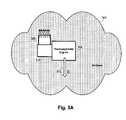
- Embodiments of the inventiondispose a thermodynamic engine in an ambient environment as illustrated schematically in FIG. 3A .
- the ambient environment 300itself is used as the heat source, with a temperature differential being provided across the thermodynamic engine 304 with a volume of heat-transport medium 308 disposed on a heat-sink structure 310 that is in thermal communication with the engine.
- the ambient environment 300has conditions that induce a phase transition in the heat-transport medium 308 .
- the inventionis not intended to be limited by the particular type of thermodynamic engine 304 that is used.
- thermodynamic enginesparticularly including thermoelectric, pyroelectric, and thermophotovoltaic engines may be used in alternative embodiments.
- phase transitionsfrom a liquid to a gas, but the invention is not limited to any particular type of phase transition.
- Different types of phase transitionsmay be used to remove energy from the heat sink in different embodiments.
- a solid-liquid phase transitionmay be used or a solid-gas phase transition may be used.
- These types of phase transitionsare generally produced by appropriate combinations of temperature and pressure of the ambient environment 300 and different embodiments of the invention may use a variety of different materials.
- watermay be used as the heat-transport medium 308 , being provided initially in either its solid or liquid states, with the pressure and temperature of the ambient environment 300 being such that it melts or evaporates in maintaining the temperature differential.
- cryogensthat have very low transition points may be used in generating greater temperature differentials.
- transitions between different molecular structuresmay be used in maintaining the temperature differential.
- transitions between polymorphs or allotropesmay be induced by conditions in the ambient environment 300 , reflected by transitions between two different crystalline structures of a solid or transitions between an amorphous structure and a crystalline structure.
- Still other types of phase transitions that maintain the temperature differential in accordance with conditions of the ambient environment 300may be used in other embodiments.
- the term “ambient” environmentis intended to refer to the overall environment within which the thermodynamic engine 304 operates.
- the volume of the ambient environment 300is large relative to the volume of the heat-transport medium 308 such that the conditions of the ambient environment are substantially unchanged by operation of the thermodynamic engine 304 .
- such conditions as the temperature, pressure, humidity, and the like of an environment within which thermodynamic engine 304 operateswill be substantially unaffected by operation of the engine 304 .
- the “ambient” environmentthus refers to the atmospheric environment where the thermodynamic engine 304 is disposed.
- an environmentis considered to be “ambient” only where it is substantially larger than the volume of heat-transport medium 308 and substantially unaffected by operation of the thermodynamic engine 304 . It is noted that this definition of an “ambient” environment does not require a static environment. Indeed, conditions of the environment may change as a result of numerous factors other than operation of the thermodynamic engine—the temperature, humidity, and other conditions may change as a result of regular diurnal cycles, as a result of changes in local weather patterns, and the like.
- the ambient environment 300comprises air that is in motion, either as a result of natural air-motion patterns generated by wind or the like or as a result of an imposition of motion by a fan or similar device.
- this air motionmay increase the rate at which the phase transition occurs and may simultaneously enhance warming of the heat-source side of the thermodynamic engine.
- the basic principle of operation of the configuration shown in FIG. 3Ais to remove energy from the heat-transport medium 308 with the induced phase transition.
- the ambient environmentprovides a heat source, providing the resultant temperature difference to drive the thermodynamic engine for extraction of energy E 312 .
- This principlepermits thermal energy to be extracted from the ambient environment as long as the conditions of that environment permit the phase transition to maintain the temperature differential.
- the ultimate source of the energy 312 derived by operation of the energyis direct or indirect solar energy.
- a heat-source structure 314supports a second heat-transfer medium 316 that undergoes a phase transition to provide a source of heat.
- the first and second heat-transfer media 308 and 316may be selected so that conditions in the ambient environment induce the respective phase transitions.
- the first heat-transfer medium 308might have a melting temperature less than the ambient temperature and the second heat-transfer medium 316 might have a melting temperature greater than the ambient temperature.
- Conditions in the ambientwould then induce a melting of the first heat-transfer medium 308 to provide a heat sink and would induce a freezing of the second heat-transfer medium 316 to provide a heat source.
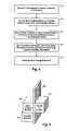
- thermodynamic engineis disposed within an ambient environment.
- a variety of different types of thermodynamic enginesmay be used in different embodiments, with Stirling engines, thermoelectric engines, pyroelectric engines, and thermophotovoltaic engines providing specific examples.
- a heat-transport mediumis provided in thermal communication with the thermodynamic engine at block 408 .
- There is considerable variety in the specific materials that may be used as the heat-transport mediumprovided that a phase transition can be induced at block 412 to produce a temperature differential across the thermodynamic engine.
- water or other materials that undergo liquid-gas, solid-liquid, or solid-gas phase transitionsmay be used, as may materials that undergo amorphous-crystalline phase transitions or transitions between different crystalline states.
- phase-change mediummay be provided to provide a heat source, as illustrated in FIG. 3B above.
- a phase-change mediummay be provided to provide a heat source, as illustrated in FIG. 3B above.
- Such embodimentspermits a realization of embodiments in which different phase changes are effected with different phase-transition media to provide heat as well as remove heat. It also permits a realization of embodiments in which a particular phase change may be used both as a heat source and as a heat sink in the system under conditions that define the directionality of the phase transition.
- thermodynamic engineis run at block 416 with the temperature differential to convert heat energy to mechanical, electrical, or some other form of nonheat energy.
- the efficiency with which this conversion is performedis relatively low, being less than 25%, less than 20%, less than 15%, less than 10%, less than 5%, less than 2%, or less than 1% in various different embodiments.
- efficiencies at this levelhave frequently been dismissed as being insufficiently effective to provide acceptable power generation.
- the focus in the arthas conventionally been concentrated on the development of high-efficiency engines. While it remains true that higher efficiencies are generally preferable to lower efficiencies, the inventors have discovered compensatory advantages with embodiments of the invention that have relatively low efficiency.
- the cost of providing a heat-transport medium that permits extraction of energy from the ambient environmentmay be substantially lower than the cost of high-efficiency engines, making the methods described herein commercially practical.
- thermodynamic engine 304may be maintained by providing new heat-transport medium to replace heat-transport medium consumed by the phase transitions.
- the replenishmentmay be achieved by restoring a prior state of the heat-transport medium, thereby permitting the same mass of material to be reused repeatedly. This is particularly advantageous when cyclic conditions of the ambient environment cause a reverse phase transition of the heat-transport medium. During this period, the thermodynamic engine may be prevented from running in reverse and thereby returning heat to the ambient environment.
- thermodynamic engineoperates to generate power from thermal gradients maintained as the heat-transport medium undergoes a transition from a first phase to a second phase.
- a second portion of the cyclewhen conditions in the ambient environment have changed so that the heat-transport medium undergoes a transition from the second phase back to the first phase while the thermodynamic engine is dormant. This prepares the system for subsequent power generation when the ambient environment cycles back to conditions similar to those that existed during the first portion of the cycle.
- phase transitions and environmental conditionsthat may combine effectively in producing such a scheme.
- the cycleis a daily cycle that has a first portion when temperatures are high and a second portion when temperatures are low, permitting the use of a heat-transport medium that undergoes a solid-liquid phase transition during the first portion and a liquid-solid phase transition during the second portion.
- Another exampleis an industrial process that has steps that produce differing levels of waste heat at different steps of the process, which can similarly be used to effect a phase transition in a material that is used to drive a thermal engine during one step of the process, with the material being returned to a different phase during a subsequent step of the process.
- thermodynamic engineis a Stirling engine 504
- the heat-transport medium 508is liquid water disposed on the heat-sink substrate 510 , with the arrangement maintaining the cold side of the Stirling engine 504 at a temperature of 285 K by evaporation
- the ambient environment 512is air at 300 K at sea level.
- the ambient air 512has a molecular density
- This amount of aircorresponds to air movement of about 300 cfm.
- a power generation system made in accordance with an embodiment of the inventionis integrated with a swamp cooler.
- a swamp cooleris a type of air conditioner that is used to cool buildings, usually in dry climates. The mechanism of operation uses evaporative cooling, making swamp coolers especially effective in areas that have a hot, dry atmosphere.
- FIG. 6One configuration is illustrated schematically in FIG. 6 . This illustration provides an example of a combined system that might be deployed to cool a building and generate electricity simultaneously.
- a swamp cooler 608acts by intaking warm, dry air 616 from the ambient environment and evaporating liquid supplied by a liquid source 612 . Evaporative cooling of the liquid may be aided with internal mechanisms such as a fan, with the swamp cooler outputting cooled air 620 that has a higher humidity than the ambient air taken into the system. The evaporative cooling that takes place within the swamp cooler 608 thus provides a phase transition from liquid to gas that may be used to drive a temperature difference of a Stirling engine 604 or other thermodynamic engine. A conduit 624 or other mechanism for providing thermal communication between the swamp cooler 624 and a sink side 628 of the engine 604 is thus provided. The engine 604 operates as described above, outputting energy E 632 , some of which may be redirected back to the swamp cooler to drive the internal fans or other mechanisms.
- liquidacts as the heat-transport medium, and may be replenished by providing additional liquid for consumption by the integrated system.
- the integrated systemmay advantageously be deployed in an attic or other hot environment that permits establishing a relatively large temperature differential with the ambient environment.
- a power generation systemmakes use of a material that may undergo structural transitions between a crystalline state and an amorphous state in response to temperature changes.
- FIG. 7in which the material 704 is in thermal contact with a thermodynamic engine 708 .
- the thermodynamic engine 708may be driven by the phase change from the amorphous state to the crystalline state, permitting energy E 712 to be generated as described above.
- the thermodynamic engine 708remains dormant as the material reverts to an amorphous form, permitting it to be used again during daylight hours for power generation.
- replenishmentis thus provided by the natural phase changes in the material 704 induced by environmental conditions.
- Deployment of such a systemmay be most advantageous in cooler environments, although the efficiency of the power-generation system will depend on the specific materials properties of the material 704 used.
Landscapes
- Engineering & Computer Science (AREA)
- Chemical & Material Sciences (AREA)
- Combustion & Propulsion (AREA)
- Mechanical Engineering (AREA)
- General Engineering & Computer Science (AREA)
- Engine Equipment That Uses Special Cycles (AREA)
Abstract
Description
With a heat capacity c of 1.381×10⁻²³J/(molecule K), the energy of the
Therefore, a 1 cm3of
(2.69×10¹⁹molecules)×(4.143×10⁻²¹J/molecule)=0.1114 J
of energy. If the
This amount of air corresponds to air movement of about 300 cfm.
Claims (24)
Priority Applications (1)
| Application Number | Priority Date | Filing Date | Title |
|---|---|---|---|
| US11/467,819US7810330B1 (en) | 2006-08-28 | 2006-08-28 | Power generation using thermal gradients maintained by phase transitions |
Applications Claiming Priority (1)
| Application Number | Priority Date | Filing Date | Title |
|---|---|---|---|
| US11/467,819US7810330B1 (en) | 2006-08-28 | 2006-08-28 | Power generation using thermal gradients maintained by phase transitions |
Publications (1)
| Publication Number | Publication Date |
|---|---|
| US7810330B1true US7810330B1 (en) | 2010-10-12 |
Family
ID=42830825
Family Applications (1)
| Application Number | Title | Priority Date | Filing Date |
|---|---|---|---|
| US11/467,819Expired - Fee RelatedUS7810330B1 (en) | 2006-08-28 | 2006-08-28 | Power generation using thermal gradients maintained by phase transitions |
Country Status (1)
| Country | Link |
|---|---|
| US (1) | US7810330B1 (en) |
Cited By (5)
| Publication number | Priority date | Publication date | Assignee | Title |
|---|---|---|---|---|
| US20130093192A1 (en)* | 2011-10-18 | 2013-04-18 | John Lee Warren | Decoupled, fluid displacer, sterling engine |
| RU2513539C1 (en)* | 2012-12-06 | 2014-04-20 | Федеральное государственное бюджетное образовательное учреждение высшего профессионального образования "Комсомольский-на-Амуре государственный технический университет" (ФГБОУВПО "КнАГТУ") | Temperature drop energy converter with electrode of liquid dielectric and high value of permittivity |
| CN103997281A (en)* | 2014-05-05 | 2014-08-20 | 江苏大学 | Secondary-power-generation thermophotovoltaic and thermoelectric co-production device |
| RU2526535C2 (en)* | 2012-12-06 | 2014-08-27 | Федеральное государственное бюджетное образовательное учреждение высшего профессионального образования "Комсомольский-на-Амуре государственный технический университет" (ФГБОУВПО "КнАГТУ") | Converter of temperature difference energy with liquid metal electrode |
| US11585329B1 (en)* | 2022-07-29 | 2023-02-21 | Eland Blockchain Fintech Inc. | Submerged geothermal power generation system |
Citations (53)
| Publication number | Priority date | Publication date | Assignee | Title |
|---|---|---|---|---|
| US3006146A (en) | 1958-09-19 | 1961-10-31 | Franklin Institute | Closed-cycle power plant |
| US3457722A (en) | 1966-04-05 | 1969-07-29 | Vannevar Bush | Hot gas engines method and apparatus |
| US3533232A (en) | 1959-11-02 | 1970-10-13 | Solid Fuels Corp | Organic fusible solid fuel binders and stabilizers |
| US3638420A (en) | 1970-10-19 | 1972-02-01 | Donald A Kelly | Thermal isolation for stirling cycle engine modules and/ modular system |
| US3772883A (en) | 1972-06-13 | 1973-11-20 | Cycle Ass | Multi-cylinder external combustion power producing system |
| US3996745A (en) | 1975-07-15 | 1976-12-14 | D-Cycle Associates | Stirling cycle type engine and method of operation |
| US3998056A (en)* | 1975-02-26 | 1976-12-21 | Clark Robert O | Solar energy apparatus and method |
| US4055962A (en)* | 1976-08-18 | 1977-11-01 | Terry Lynn E | Hydrogen-hydride absorption systems and methods for refrigeration and heat pump cycles |
| US4148195A (en) | 1977-12-12 | 1979-04-10 | Joseph Gerstmann | Liquid piston heat-actuated heat pump and methods of operating same |
| US4149389A (en)* | 1978-03-06 | 1979-04-17 | The Trane Company | Heat pump system selectively operable in a cascade mode and method of operation |
| US4313304A (en)* | 1979-07-26 | 1982-02-02 | The United States Of America As Represented By The United States Department Of Energy | Radiant energy collection and conversion apparatus and method |
| US4339930A (en) | 1980-07-03 | 1982-07-20 | The United States Of America As Represented By The Secretary Of The Navy | Control system for solar-assisted heat pump system |
| US4412418A (en) | 1979-11-26 | 1983-11-01 | Sunpower, Inc. | Hydrodynamic lubrication system for piston devices particularly Stirling engines |
| US4433550A (en) | 1982-04-28 | 1984-02-28 | The United States Of America As Represented By The Secretary Of The Army | Free piston displacer control means |
| US4522033A (en) | 1984-07-02 | 1985-06-11 | Cvi Incorporated | Cryogenic refrigerator with gas spring loaded valve |
| US4532778A (en)* | 1979-11-16 | 1985-08-06 | Rocket Research Company | Chemical heat pump and chemical energy storage system |
| US4586334A (en) | 1985-01-23 | 1986-05-06 | Nilsson Sr Jack E | Solar energy power generation system |
| US4753072A (en) | 1987-02-11 | 1988-06-28 | Stirling Power Systems Corporation | Stirling engine heating system |
| US4894989A (en) | 1986-08-29 | 1990-01-23 | Aisin Seiki Kabushiki Kaisha | Heater for a stirling engine |
| US4897997A (en) | 1988-08-19 | 1990-02-06 | Stirling Thermal Motors, Inc. | Shell and tube heat pipe condenser |
| DE3834703A1 (en)* | 1988-10-07 | 1990-04-12 | Roland Treptow | Solar thermal power station (plant) using environmental heat |
| US4981014A (en)* | 1986-12-05 | 1991-01-01 | Gallagher Paul H | Atmospheric pressure power plant |
| US5010734A (en) | 1989-08-31 | 1991-04-30 | Goldstar Co., Ltd. | Cooling system for a stirling engine |
| JPH0493559A (en) | 1990-08-10 | 1992-03-26 | Naoji Isshiki | Reverse stirling refrigeration machine having circulating oil |
| US5115157A (en) | 1988-12-21 | 1992-05-19 | Technion Research & Development Foundation, Ltd. | Liquid sealed vane oscillators |
| US5180035A (en) | 1990-09-07 | 1993-01-19 | Union Special Corporation | Oil pumps for sewing machines |
| US5195321A (en) | 1992-03-04 | 1993-03-23 | Clovis Thermal Corporation | Liquid piston heat engine |
| US5228293A (en) | 1992-07-06 | 1993-07-20 | Mechanical Technology Inc. | Low temperature solar-to-electric power conversion system |
| US5343632A (en) | 1992-04-10 | 1994-09-06 | Advanced Dryer Systems, Inc. | Closed-loop drying process and system |
| US5428653A (en) | 1993-08-05 | 1995-06-27 | University Of New Mexico | Apparatus and method for nuclear power and propulsion |
| US5438846A (en) | 1994-05-19 | 1995-08-08 | Datta; Chander | Heat-pump with sub-cooling heat exchanger |
| US5638684A (en) | 1995-01-16 | 1997-06-17 | Bayer Aktiengesellschaft | Stirling engine with injection of heat transfer medium |
| US5706659A (en) | 1996-01-26 | 1998-01-13 | Stirling Thermal Motors, Inc. | Modular construction stirling engine |
| US5782084A (en) | 1995-06-07 | 1998-07-21 | Hyrum T. Jarvis | Variable displacement and dwell drive for stirling engine |
| US5875863A (en) | 1996-03-22 | 1999-03-02 | Hyrum T. Jarvis | Power system for extending the effective range of hybrid electric vehicles |
| DE19843600A1 (en) | 1998-09-23 | 1999-03-04 | Fritz Kunkel | Improved efficiency internal combustion engine |
| US5899071A (en) | 1996-08-14 | 1999-05-04 | Mcdonnell Douglas Corporation | Adaptive thermal controller for heat engines |
| US5916140A (en) | 1997-08-21 | 1999-06-29 | Hydrotherm Power Corporation | Hydraulic engine powered by introduction and removal of heat from a working fluid |
| US5918463A (en) | 1997-01-07 | 1999-07-06 | Stirling Technology Company | Burner assembly for heater head of a stirling cycle machine |
| US5934076A (en) | 1992-12-01 | 1999-08-10 | National Power Plc | Heat engine and heat pump |
| US6286310B1 (en) | 1999-12-17 | 2001-09-11 | Fantom Technologies Inc. | Heat engine |
| US6305442B1 (en) | 1999-11-06 | 2001-10-23 | Energy Conversion Devices, Inc. | Hydrogen-based ecosystem |
| US6330800B1 (en) | 1999-04-16 | 2001-12-18 | Raytheon Company | Apparatus and method for achieving temperature stability in a two-stage cryocooler |
| US6470679B1 (en) | 1997-09-26 | 2002-10-29 | Thomas Ertle | Apparatus and method for transferring entropy with the aid of a thermodynamic cycle |
| US6536207B1 (en) | 2000-03-02 | 2003-03-25 | New Power Concepts Llc | Auxiliary power unit |
| US6606860B2 (en) | 2001-10-24 | 2003-08-19 | Mcfarland Rory S. | Energy conversion method and system with enhanced heat engine |
| US6625992B2 (en)* | 2000-01-11 | 2003-09-30 | American Superconductor Corporation | Cooling system for HTS machines |
| US6701721B1 (en) | 2003-02-01 | 2004-03-09 | Global Cooling Bv | Stirling engine driven heat pump with fluid interconnection |
| US20040118449A1 (en) | 2002-12-20 | 2004-06-24 | Murphy Terrence H. | Solar dish concentrator with a molten salt receiver incorporating thermal energy storage |
| US20050172623A1 (en) | 2002-03-05 | 2005-08-11 | Hurt Robert D. | Rakh cycle engine |
| US6948315B2 (en)* | 2004-02-09 | 2005-09-27 | Timothy Michael Kirby | Method and apparatus for a waste heat recycling thermal power plant |
| US20050279094A1 (en) | 2003-09-02 | 2005-12-22 | Kazutora Yoshino | Almost-perpetual ecology system |
| US6996988B1 (en) | 2003-01-28 | 2006-02-14 | Emc2 | AutoSolar Thermal Electric Conversion (ASTEC) solar power system |
- 2006
- 2006-08-28USUS11/467,819patent/US7810330B1/ennot_activeExpired - Fee Related
Patent Citations (53)
| Publication number | Priority date | Publication date | Assignee | Title |
|---|---|---|---|---|
| US3006146A (en) | 1958-09-19 | 1961-10-31 | Franklin Institute | Closed-cycle power plant |
| US3533232A (en) | 1959-11-02 | 1970-10-13 | Solid Fuels Corp | Organic fusible solid fuel binders and stabilizers |
| US3457722A (en) | 1966-04-05 | 1969-07-29 | Vannevar Bush | Hot gas engines method and apparatus |
| US3638420A (en) | 1970-10-19 | 1972-02-01 | Donald A Kelly | Thermal isolation for stirling cycle engine modules and/ modular system |
| US3772883A (en) | 1972-06-13 | 1973-11-20 | Cycle Ass | Multi-cylinder external combustion power producing system |
| US3998056A (en)* | 1975-02-26 | 1976-12-21 | Clark Robert O | Solar energy apparatus and method |
| US3996745A (en) | 1975-07-15 | 1976-12-14 | D-Cycle Associates | Stirling cycle type engine and method of operation |
| US4055962A (en)* | 1976-08-18 | 1977-11-01 | Terry Lynn E | Hydrogen-hydride absorption systems and methods for refrigeration and heat pump cycles |
| US4148195A (en) | 1977-12-12 | 1979-04-10 | Joseph Gerstmann | Liquid piston heat-actuated heat pump and methods of operating same |
| US4149389A (en)* | 1978-03-06 | 1979-04-17 | The Trane Company | Heat pump system selectively operable in a cascade mode and method of operation |
| US4313304A (en)* | 1979-07-26 | 1982-02-02 | The United States Of America As Represented By The United States Department Of Energy | Radiant energy collection and conversion apparatus and method |
| US4532778A (en)* | 1979-11-16 | 1985-08-06 | Rocket Research Company | Chemical heat pump and chemical energy storage system |
| US4412418A (en) | 1979-11-26 | 1983-11-01 | Sunpower, Inc. | Hydrodynamic lubrication system for piston devices particularly Stirling engines |
| US4339930A (en) | 1980-07-03 | 1982-07-20 | The United States Of America As Represented By The Secretary Of The Navy | Control system for solar-assisted heat pump system |
| US4433550A (en) | 1982-04-28 | 1984-02-28 | The United States Of America As Represented By The Secretary Of The Army | Free piston displacer control means |
| US4522033A (en) | 1984-07-02 | 1985-06-11 | Cvi Incorporated | Cryogenic refrigerator with gas spring loaded valve |
| US4586334A (en) | 1985-01-23 | 1986-05-06 | Nilsson Sr Jack E | Solar energy power generation system |
| US4894989A (en) | 1986-08-29 | 1990-01-23 | Aisin Seiki Kabushiki Kaisha | Heater for a stirling engine |
| US4981014A (en)* | 1986-12-05 | 1991-01-01 | Gallagher Paul H | Atmospheric pressure power plant |
| US4753072A (en) | 1987-02-11 | 1988-06-28 | Stirling Power Systems Corporation | Stirling engine heating system |
| US4897997A (en) | 1988-08-19 | 1990-02-06 | Stirling Thermal Motors, Inc. | Shell and tube heat pipe condenser |
| DE3834703A1 (en)* | 1988-10-07 | 1990-04-12 | Roland Treptow | Solar thermal power station (plant) using environmental heat |
| US5115157A (en) | 1988-12-21 | 1992-05-19 | Technion Research & Development Foundation, Ltd. | Liquid sealed vane oscillators |
| US5010734A (en) | 1989-08-31 | 1991-04-30 | Goldstar Co., Ltd. | Cooling system for a stirling engine |
| JPH0493559A (en) | 1990-08-10 | 1992-03-26 | Naoji Isshiki | Reverse stirling refrigeration machine having circulating oil |
| US5180035A (en) | 1990-09-07 | 1993-01-19 | Union Special Corporation | Oil pumps for sewing machines |
| US5195321A (en) | 1992-03-04 | 1993-03-23 | Clovis Thermal Corporation | Liquid piston heat engine |
| US5343632A (en) | 1992-04-10 | 1994-09-06 | Advanced Dryer Systems, Inc. | Closed-loop drying process and system |
| US5228293A (en) | 1992-07-06 | 1993-07-20 | Mechanical Technology Inc. | Low temperature solar-to-electric power conversion system |
| US5934076A (en) | 1992-12-01 | 1999-08-10 | National Power Plc | Heat engine and heat pump |
| US5428653A (en) | 1993-08-05 | 1995-06-27 | University Of New Mexico | Apparatus and method for nuclear power and propulsion |
| US5438846A (en) | 1994-05-19 | 1995-08-08 | Datta; Chander | Heat-pump with sub-cooling heat exchanger |
| US5638684A (en) | 1995-01-16 | 1997-06-17 | Bayer Aktiengesellschaft | Stirling engine with injection of heat transfer medium |
| US5782084A (en) | 1995-06-07 | 1998-07-21 | Hyrum T. Jarvis | Variable displacement and dwell drive for stirling engine |
| US5706659A (en) | 1996-01-26 | 1998-01-13 | Stirling Thermal Motors, Inc. | Modular construction stirling engine |
| US5875863A (en) | 1996-03-22 | 1999-03-02 | Hyrum T. Jarvis | Power system for extending the effective range of hybrid electric vehicles |
| US5899071A (en) | 1996-08-14 | 1999-05-04 | Mcdonnell Douglas Corporation | Adaptive thermal controller for heat engines |
| US5918463A (en) | 1997-01-07 | 1999-07-06 | Stirling Technology Company | Burner assembly for heater head of a stirling cycle machine |
| US5916140A (en) | 1997-08-21 | 1999-06-29 | Hydrotherm Power Corporation | Hydraulic engine powered by introduction and removal of heat from a working fluid |
| US6470679B1 (en) | 1997-09-26 | 2002-10-29 | Thomas Ertle | Apparatus and method for transferring entropy with the aid of a thermodynamic cycle |
| DE19843600A1 (en) | 1998-09-23 | 1999-03-04 | Fritz Kunkel | Improved efficiency internal combustion engine |
| US6330800B1 (en) | 1999-04-16 | 2001-12-18 | Raytheon Company | Apparatus and method for achieving temperature stability in a two-stage cryocooler |
| US6305442B1 (en) | 1999-11-06 | 2001-10-23 | Energy Conversion Devices, Inc. | Hydrogen-based ecosystem |
| US6286310B1 (en) | 1999-12-17 | 2001-09-11 | Fantom Technologies Inc. | Heat engine |
| US6625992B2 (en)* | 2000-01-11 | 2003-09-30 | American Superconductor Corporation | Cooling system for HTS machines |
| US6536207B1 (en) | 2000-03-02 | 2003-03-25 | New Power Concepts Llc | Auxiliary power unit |
| US6606860B2 (en) | 2001-10-24 | 2003-08-19 | Mcfarland Rory S. | Energy conversion method and system with enhanced heat engine |
| US20050172623A1 (en) | 2002-03-05 | 2005-08-11 | Hurt Robert D. | Rakh cycle engine |
| US20040118449A1 (en) | 2002-12-20 | 2004-06-24 | Murphy Terrence H. | Solar dish concentrator with a molten salt receiver incorporating thermal energy storage |
| US6996988B1 (en) | 2003-01-28 | 2006-02-14 | Emc2 | AutoSolar Thermal Electric Conversion (ASTEC) solar power system |
| US6701721B1 (en) | 2003-02-01 | 2004-03-09 | Global Cooling Bv | Stirling engine driven heat pump with fluid interconnection |
| US20050279094A1 (en) | 2003-09-02 | 2005-12-22 | Kazutora Yoshino | Almost-perpetual ecology system |
| US6948315B2 (en)* | 2004-02-09 | 2005-09-27 | Timothy Michael Kirby | Method and apparatus for a waste heat recycling thermal power plant |
Non-Patent Citations (5)
| Title |
|---|
| "Low-Cost Solar-Thermal-Electric Power Generation," author unknown, found online on Jul. 18, 2008 at http://www.cs.berkeley.edu/~artin/Research/research.html, 6 pages. |
| "Low-Cost Solar-Thermal-Electric Power Generation," author unknown, found online on Jul. 18, 2008 at http://www.cs.berkeley.edu/˜artin/Research/research.html, 6 pages. |
| Der Menassians, Artur, "Stirling Engines for Low-Temperature Solar-Thermal-Electric Power Generation," Dissertation Talk, Nov. 19, 2007, 34 pages. |
| Der Menassians, Artur, "Stirling Engines for Low-Temperature Solar-Thermal-Electric Power Generation," Written Dissertation from the University of CA Berkeley, 2007, 205 pages. |
| Senft, James R, "An Introduction to Stirling Engines", Moriya Press, 1993, pp. 40-43. |
Cited By (6)
| Publication number | Priority date | Publication date | Assignee | Title |
|---|---|---|---|---|
| US20130093192A1 (en)* | 2011-10-18 | 2013-04-18 | John Lee Warren | Decoupled, fluid displacer, sterling engine |
| RU2513539C1 (en)* | 2012-12-06 | 2014-04-20 | Федеральное государственное бюджетное образовательное учреждение высшего профессионального образования "Комсомольский-на-Амуре государственный технический университет" (ФГБОУВПО "КнАГТУ") | Temperature drop energy converter with electrode of liquid dielectric and high value of permittivity |
| RU2526535C2 (en)* | 2012-12-06 | 2014-08-27 | Федеральное государственное бюджетное образовательное учреждение высшего профессионального образования "Комсомольский-на-Амуре государственный технический университет" (ФГБОУВПО "КнАГТУ") | Converter of temperature difference energy with liquid metal electrode |
| CN103997281A (en)* | 2014-05-05 | 2014-08-20 | 江苏大学 | Secondary-power-generation thermophotovoltaic and thermoelectric co-production device |
| CN103997281B (en)* | 2014-05-05 | 2016-08-24 | 江苏大学 | A kind of thermal photovoltaic cogeneration system of secondary electricity generation |
| US11585329B1 (en)* | 2022-07-29 | 2023-02-21 | Eland Blockchain Fintech Inc. | Submerged geothermal power generation system |
Similar Documents
| Publication | Publication Date | Title |
|---|---|---|
| US8539771B2 (en) | Power generation and space conditioning using a thermodynamic engine driven through environmental heating and cooling | |
| EP2406485B1 (en) | Heat engine with regenerator and timed gas exchange | |
| US4413474A (en) | Mechanical arrangements for Stirling-cycle, reciprocating thermal machines | |
| US5899071A (en) | Adaptive thermal controller for heat engines | |
| US4429732A (en) | Regenerator structure for stirling-cycle, reciprocating thermal machines | |
| US20090000294A1 (en) | Power Plant with Heat Transformation | |
| US4414814A (en) | Solar heat engines | |
| US20150135714A1 (en) | Pressure power unit | |
| US7810330B1 (en) | Power generation using thermal gradients maintained by phase transitions | |
| Meir et al. | Low-temperature energy conversion using a phase-change acoustic heat engine | |
| US4794752A (en) | Vapor stirling heat machine | |
| Shendage et al. | Cyclic analysis and optimization of design parameters for Beta-configuration Stirling engine using rhombic drive | |
| US3971230A (en) | Stirling cycle engine and refrigeration systems | |
| US20050268607A1 (en) | Thermohydrodynamic power amplifier | |
| US5822964A (en) | Hot-gas engine electric heater | |
| JP2005537433A5 (en) | ||
| US8596060B2 (en) | Systems and method for producing mechanical energy | |
| US3478511A (en) | Closed-cycle gas engine | |
| Spencer | A comprehensive review of small solar-powered heat engines: Part III. Research since 1950—“unconventional” engines up to 100 kW | |
| EP0078849B1 (en) | Regenerator structure for stirling-cycle, reciprocating, thermal machines | |
| Thombare | Stirling Engine Micro-CHP System | |
| CA1226443A (en) | Stirling-cycle, reciprocating, thermal machines | |
| JP2007023885A (en) | Stirling engine using liquefied substance for working gas | |
| JP2007023885A5 (en) | ||
| Grosu et al. | 4.1 Stirling engines |
Legal Events
| Date | Code | Title | Description |
|---|---|---|---|
| AS | Assignment | Owner name:COOL ENERGY, INC., TENNESSEE Free format text:ASSIGNMENT OF ASSIGNORS INTEREST;ASSIGNORS:WEAVER, SAMUEL C.;WEAVER, DANIEL;WEAVER, SAMUEL P.;SIGNING DATES FROM 20060907 TO 20060914;REEL/FRAME:018311/0734 | |
| STCF | Information on status: patent grant | Free format text:PATENTED CASE | |
| FPAY | Fee payment | Year of fee payment:4 | |
| FEPP | Fee payment procedure | Free format text:MAINTENANCE FEE REMINDER MAILED (ORIGINAL EVENT CODE: REM.) | |
| FEPP | Fee payment procedure | Free format text:7.5 YR SURCHARGE - LATE PMT W/IN 6 MO, SMALL ENTITY (ORIGINAL EVENT CODE: M2555); ENTITY STATUS OF PATENT OWNER: SMALL ENTITY | |
| MAFP | Maintenance fee payment | Free format text:PAYMENT OF MAINTENANCE FEE, 8TH YR, SMALL ENTITY (ORIGINAL EVENT CODE: M2552); ENTITY STATUS OF PATENT OWNER: SMALL ENTITY Year of fee payment:8 | |
| FEPP | Fee payment procedure | Free format text:MAINTENANCE FEE REMINDER MAILED (ORIGINAL EVENT CODE: REM.); ENTITY STATUS OF PATENT OWNER: SMALL ENTITY | |
| LAPS | Lapse for failure to pay maintenance fees | Free format text:PATENT EXPIRED FOR FAILURE TO PAY MAINTENANCE FEES (ORIGINAL EVENT CODE: EXP.); ENTITY STATUS OF PATENT OWNER: SMALL ENTITY | |
| STCH | Information on status: patent discontinuation | Free format text:PATENT EXPIRED DUE TO NONPAYMENT OF MAINTENANCE FEES UNDER 37 CFR 1.362 | |
| FP | Lapsed due to failure to pay maintenance fee | Effective date:20221012 |