US7809393B2 - Method and arrangement for setting the transmission of a mobile communication device - Google Patents
Method and arrangement for setting the transmission of a mobile communication deviceDownload PDFInfo
- Publication number
- US7809393B2 US7809393B2US10/555,755US55575504AUS7809393B2US 7809393 B2US7809393 B2US 7809393B2US 55575504 AUS55575504 AUS 55575504AUS 7809393 B2US7809393 B2US 7809393B2
- Authority
- US
- United States
- Prior art keywords
- analog
- gain
- digital
- signals
- transmitted power
- Prior art date
- Legal status (The legal status is an assumption and is not a legal conclusion. Google has not performed a legal analysis and makes no representation as to the accuracy of the status listed.)
- Active, expires
Links
Images


Classifications
- H—ELECTRICITY
- H04—ELECTRIC COMMUNICATION TECHNIQUE
- H04W—WIRELESS COMMUNICATION NETWORKS
- H04W52/00—Power management, e.g. Transmission Power Control [TPC] or power classes
- H04W52/04—Transmission power control [TPC]
- H04W52/52—Transmission power control [TPC] using AGC [Automatic Gain Control] circuits or amplifiers
- H—ELECTRICITY
- H04—ELECTRIC COMMUNICATION TECHNIQUE
- H04W—WIRELESS COMMUNICATION NETWORKS
- H04W52/00—Power management, e.g. Transmission Power Control [TPC] or power classes
- H04W52/04—Transmission power control [TPC]
- H04W52/06—TPC algorithms
- H04W52/08—Closed loop power control
Definitions
- the inventionrelates to a method and an arrangement for setting the transmitted power of a mobile communication device, particularly for a UMTS (universal mobile telecommunication system) system.
- UMTSuniversal mobile telecommunication system
- the transmitted power of the mobile communication deviceIn mobile communication systems, and particularly in a UMTS system, there is a requirement for the transmitted power of the mobile communication device to be set with great accuracy.
- the base stations of the mobile communication systemcurrently specify at what power the mobile communication device is to transmit at any given time.
- a relative accuracy of ⁇ 0.5 dBis laid down for the transmitted power.
- the transmitted powercan be accurately set, thus enabling its relative accuracy to meet even the stringent demands of the UMTS over a wide dynamic range.
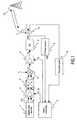
- FIG. 1is a block diagram relating to the setting of transmitted power in a mobile communication device.
- FIG. 2shows the construction of a digital, two-stage amplifier belonging to the mobile communication device
- FIG. 3is a block circuit diagram that corresponds to FIG. 1 and relates to the self-calibration process.
- a digital data source 1makes available the information to be transmitted, which is in the form of complex values, as two digital signals I 1 and Q 1 .
- the digital signals I 1 and Q 1are amplified in a digital amplifier 8 to give signals I 2 and Q 2 and these are converted by a digital-to-analog converter 2 into analog signals I 3 and Q 3 .
- the latterare modulated in a modulator 3 onto a carrier frequency f T , giving a modulated analog signal X 3 . There is no need for modulation to an intermediate frequency.
- the modulated analog signal X 3is amplified in an analog amplifier 4 (see FIG. 1 ), or in a plurality of analog amplifiers 4 connected in series (see FIG. 3 ), to give a signal X 4 , in which case the analog gain may, depending on the requirements at the time, even be less than 1.
- the analog signal X 4is fed to a power output stage 6 and is applied as a signal z(t) to an antenna 7 of the mobile communication device.
- the gain factors of the digital amplifier 8can be set via control lines g 1 and g 2 and the gain factors of the analog amplifier 4 can be set via a control line g 3 (see FIG. 1 ) or via control lines g 3 , g 4 , g 5 (see FIG. 3 ).
- a power sensor 9measures the actual transmitted power of the signal z(t) that is applied to the antenna 7 and transmits a corresponding signal p(t) giving this information to the control circuit 5 .
- the desired value for transmitted power at the timeis transmitted from that base station 12 that is receiving the transmitted signal from the mobile communication device by uplink, the transmission being performed by downlink to the mobile communication device.
- the base station 12specifies the change that is necessary or desired to the transmitted power.
- a conventional duplexer 13separates the uplink signal from the downlink signal, which is fed via a reception path 14 to the control circuit 5 .
- the control circuit 5determines, from the desired value for the transmitted signal and from the actual value of the transmitted signal, the gain factors that are to be set at the digital amplifier 8 and the analog amplifier 4 or amplifiers 4 under the operating circumstances at the time.
- control circuit 5By means of the control circuit 5 , the overall gain needed for the transmitted power asked for at the time is apportioned between the digital amplifier 8 and the analog amplifier/amplifiers 4 .
- a high proportion of the overall gainis apportioned to the digital amplifier 8 , with the dynamic range of the digital-to-analog converter 2 being exploited to the maximum possible degree.
- a gain factoris set at the analog amplifier 4 or at the analog amplifiers 4 , with the sum of the levels of the digital and analog gains producing exactly the desired level of transmitted power that is being asked for at the time by the base station 12 .
- the control circuit 5controls the digital amplifier 8 in this case in such a way that the digital values of the signal I 1 and Q 1 are altered sufficiently to allow a comparatively low analog gain in the analog amplifier or amplifiers 4 to be enough to allow the transmitted power being asked for to be achieved.
- a high signal-to-noise ratiois obtained in this way.
- the change in the particular digital gain factormay be positive or negative. If the change is positive, then some actual amplification takes place. If the change is negative, then it is attenuation that takes place.
- the desired level of transmitted power that is asked for by the particular base stationmay rise or fall swiftly, within a few milliseconds, for example.
- the control circuit 5changes the digital and analog gains with a corresponding swiftness.
- gainis to be changed, starting from a previous base state, by +12.5 dB and
- the analog amplifier 4 or the analog amplifiers 4is/are to be controlled only in steps of . . . 10 dB, 12 dB, 14 dB, 16 dB . . . and
- the digital amplifier 8in the base state, the digital amplifier 8 is only able to attenuate, because it is being fully driven at its maximum gain in the dynamic range of the digital-to-analog converter.
- the analog amplifier 4is then set to +14 dB and the digital amplifier 8 is set to an attenuation of ⁇ 1.5 dB.
- the gainis to be changed by +12 dB, then under the above assumptions the analog amplifier 4 will be set to +12 dB and the digital amplifier to 0 dB.
- the gain factor of the analog amplifier 4does not have a linear range of adjustment but can only be adjusted in steps.
- An analog gain factor that differs from the overall gain desired at the timecan then be supplemented by the digital amplifier 8 in such a way that the desired overall gain is set with sufficient accuracy.
- What is also beneficial in this caseis the fact that the digital gain, unlike the analog gain, is not dependent on fluctuations in voltage and fluctuations in temperature.
- the digital amplifier 8may be constructed from respective first stages 15 and 15 ′ and respective second stages 16 and 16 ′ (see FIG. 2 ).
- the first stages 15 , 15 ′are used to set a high signal level using finely graduated factors.
- the second stages 16 , 16 ′operate with a coarser graduation. With them, low signal levels are made available when the signal-to-noise ratio required is reduced. This is useful in a UMTS, for example, if very low transmitted powers are to be obtained while less stringent demands are to be met in respect of the signal-to-noise ratio and if the dynamic range of the analog amplifier 4 is designed to be small to allow a high signal-to-noise ratio to be achieved.
- N3 programmable amplifiers 4 connected in series.
- the parameters that determine the gain factors for the digital gain and the analog gainare stored in the micro-controller 5 . It is possible in this way for self-calibration of the analog amplifiers to be performed in the following manner.
- the self-calibrationsimplifies the calibration of the analog amplifier or analog amplifiers 4 when the mobile communication device is being manufactured. Also, the self-calibration may take place repeatedly even during the time when the mobile communication device is operating, which means that the effects of changes in operating voltage and changes in temperature on the transmitted power are compensated for.
- the gain of the ⁇ th of the N programmable analog amplifiers 4be: A ⁇ [k ⁇ ] where k ⁇ ⁇ [1, . . . , n ⁇ ], ⁇ [1, . . . , N], and where k ⁇ is the gain-determining parameter of the ⁇ th amplifier.
- the gain of the digital amplifierbe: D[k] where k ⁇ [1, . . . , m], and where k is the gain-determining parameter of the digital gain.
- the gain made up of the individual gainsis thus, ignoring the constant effects of the digital-to-analog converter 2 and the modulator 3 :
- the overall gain with a first set of parameters k (1) , k ⁇ (1)will be designated G (1) below.
- the overall gain with a second set of parameters k (2) , k ⁇ (2)will be designated G (2) below.
- the output power that effectively results from thisis measured from z(t) by means of the uncalibrated power sensor 9 . What is obtained is a measured gain of M (1) ⁇ G (1) , where M (1) is a power transmission factor.
- k (1) ⁇ k (2) k ⁇ (1)k ⁇ (2) ⁇ [1 ,N]/ ⁇ , k ⁇ (1) ⁇ k ⁇ (2) where ⁇ is between 1 and N.
- G (1)may for example be:
- G (2)may then be
- the output power that results from the second set of parametersis then measured.
- a measured gain M (2) ⁇ G (2)is obtained when this is done.
- a relationshipis defined between this measurement and the measurement M (1) ⁇ G (1) :
- the self-calibrationmay also take place in the following manner:
- a first overall gain G (1)is set and M (1) G (1) is measured by the power sensor 9 .
- a second overall gain G (2) having altered parametersis then set and the digital gain D (2) is changed until such time as the power M (2) G (2) measured for G (2) exactly corresponds to the first measurement M (1) G (1) .
- the analog gain A 1 [ 2 ]is not, as it should be in theory, 1 dB but 1.25 dB in this case then, in this procedure, the digital gain D[ 2 ] is changed by ⁇ 0.25 dB, thus giving 1 dB.
- An entrycan then be made in the table of corrections to say that A 1 [ 2 ] is not 1 dB but 1.25 dB. With this procedure, any non-linear measurement of power that may occur is compensated for and the ratio G (2) /G (1) of the levels of gain is fixed with greater accuracy.
- a further use for digital amplificationarises with UMTS when only very low transmitted levels are to be set.
- the UMTS standardlowers the requirements to be met by the signal-to-noise ratio, which means that the analog-to-digital converter no longer has to be fully modulated to allow them to be met.
- the range of adjustment of the digital amplifiercan thus be widened to cover smaller factors because additional attenuation can be produced less expensively and with greater accuracy in the digital amplifier 8 than in the analog amplifiers 4 .
- the setting of a very low transmitted levelcan be accomplished as follows in the foregoing example.
- the analog amplifier or the analog amplifiersare set to their lowest gain (0 dB), and the digital amplifier 8 (see FIG. 2 ) is set to ⁇ 20 dB.
Landscapes
- Engineering & Computer Science (AREA)
- Computer Networks & Wireless Communication (AREA)
- Signal Processing (AREA)
- Transmitters (AREA)
- Amplifiers (AREA)
- Mobile Radio Communication Systems (AREA)
- Control Of Amplification And Gain Control (AREA)
Abstract
Description
Aν[kν] where kνε[1, . . . , nν],νε[1, . . . , N],
and where kν is the gain-determining parameter of the νth amplifier.
D[k] where kε[1, . . . , m],
and where k is the gain-determining parameter of the digital gain.
| Parameters | D[k] | A1[k1] | A2[k2] | A3[k3] | A4[k4] |
| k, kv | m = 32 | n1= 4 | n2= 2 | n3= 2 | n4= 2 |
| 1 | 0 dB | 0 dB | 0 dB | 0 dB | 0 |
| 2 | 0.25 | 1 | 4 | 4 | 16 dB |
| 3 | 0.5 | 2 | |||
| 4 | 0.75 dB | 3 | |||
| 5 | 1 dB | ||||
| . . . | . . . | ||||
| 32 | 7.75 dB | ||||
G(1)=D[k(1)]·ΠAν[kν(1)].
The output power that effectively results from this is measured from z(t) by means of the
G(1)=G(2)=D[k(2)]·ΠAν[kν(1)].
What are to apply in this equation are:
k(1)≠k(2)
kν(1)=kν(2)∀νε[1,N]/λ,
kλ(1)≠kλ(2)
where λ is between 1 and N.
G(2)may then be
λ being equal to 1 in this case.
Because G(1)and G(2)are intended to be approximately equal, the measured difference between M(1)and M(2)can be ignored and it can thus be stated that M(1)=M(2).
| Parameters | ΔA1[k1] | ΔA2[k2] | ΔA3[k3] | ΔA4[k4] |
| k, kν | n1= 4 | n2= 2 | n3= 2 | n4= 2 |
| 1 | 0 dB | 0.1 dB | −0.2 dB | 0.6 |
| 2 | 0.2 dB | −0.3 dB | 0.2 dB | −0.7 dB |
| 3 | 0.1 | |||
| 4 | 0.6 dB | |||
Claims (20)
Applications Claiming Priority (4)
| Application Number | Priority Date | Filing Date | Title |
|---|---|---|---|
| EP03101299.0 | 2003-05-09 | ||
| EP03101299 | 2003-05-09 | ||
| EP03101299 | 2003-05-09 | ||
| PCT/IB2004/050610WO2004100396A1 (en) | 2003-05-09 | 2004-05-06 | Method and arrangement for setting the transmission power of a mobile communication device |
Publications (2)
| Publication Number | Publication Date |
|---|---|
| US20080200199A1 US20080200199A1 (en) | 2008-08-21 |
| US7809393B2true US7809393B2 (en) | 2010-10-05 |
Family
ID=33427210
Family Applications (1)
| Application Number | Title | Priority Date | Filing Date |
|---|---|---|---|
| US10/555,755Active2026-04-01US7809393B2 (en) | 2003-05-09 | 2004-05-06 | Method and arrangement for setting the transmission of a mobile communication device |
Country Status (7)
| Country | Link |
|---|---|
| US (1) | US7809393B2 (en) |
| EP (1) | EP1625675B1 (en) |
| JP (1) | JP2006526916A (en) |
| CN (1) | CN1784837B (en) |
| AT (1) | ATE372611T1 (en) |
| DE (1) | DE602004008769T2 (en) |
| WO (1) | WO2004100396A1 (en) |
Cited By (4)
| Publication number | Priority date | Publication date | Assignee | Title |
|---|---|---|---|---|
| US20140355712A1 (en)* | 2013-05-31 | 2014-12-04 | Qualcomm Incorporated | Dynamic gain for dac illumination control |
| US20150042497A1 (en)* | 2013-08-07 | 2015-02-12 | Realtek Semiconductor Corporation | Communication device and method capable of power calibration |
| US20150043625A1 (en)* | 2013-08-12 | 2015-02-12 | Broadcom Corporation | Upstream power amplifier |
| US20180040964A1 (en)* | 2015-04-30 | 2018-02-08 | Ntt Docomo, Inc. | Radio base station |
Families Citing this family (10)
| Publication number | Priority date | Publication date | Assignee | Title |
|---|---|---|---|---|
| US8170511B2 (en) | 2006-08-14 | 2012-05-01 | St-Ericsson Sa | Equalizer system for emitting a quasi-constant power output RF signal in a frequency band |
| CN1964213B (en)* | 2006-12-13 | 2011-11-23 | 北京中星微电子有限公司 | A method to improve linearity of radio-frequency power amplifier, system and baseband |
| US7953180B2 (en)* | 2007-01-12 | 2011-05-31 | Panasonic Corporation | Transmission power control method and transmission apparatus |
| US7941109B2 (en)* | 2007-01-12 | 2011-05-10 | Panasonic Corporation | Polar modulation transmission apparatus and transmission power control method |
| US8126452B2 (en) | 2007-11-29 | 2012-02-28 | Intel Mobile Communications GmbH | Systems and methods for self-calibrating transceivers |
| FR2924544B1 (en)* | 2007-12-03 | 2011-04-22 | Wavecom | METHOD FOR CALIBRATING TRANSMISSION CHAIN, COMPUTER PROGRAM PRODUCT, CORRESPONDING STORAGE MEDIUM AND CALIBRATION DEVICE |
| JP5643785B2 (en)* | 2012-06-15 | 2014-12-17 | 株式会社東芝 | Digital broadcast transmitter and exciter |
| US8836424B2 (en)* | 2012-07-16 | 2014-09-16 | Intel Mobile Communications GmbH | Amplifier circuit, method and mobile communication device |
| CN104378168B (en)* | 2013-08-13 | 2017-04-12 | 瑞昱半导体股份有限公司 | Communication device and method with power correction function |
| DE102016108206B4 (en)* | 2016-05-03 | 2020-09-10 | Bury Sp.Z.O.O | Circuit arrangement and method for attenuation compensation in an antenna signal connection |
Citations (106)
| Publication number | Priority date | Publication date | Assignee | Title |
|---|---|---|---|---|
| US4551688A (en)* | 1984-05-23 | 1985-11-05 | Rockwell International Corporation | Delay compensated automatic gain control |
| US4748326A (en)* | 1985-12-27 | 1988-05-31 | Fuji Photo Film Co., Ltd. | Radiation image read-out apparatus |
| US5097197A (en)* | 1990-08-10 | 1992-03-17 | Sharp Kabushiki Kaisha | Signal level attenuating device |
| US5541606A (en)* | 1995-02-02 | 1996-07-30 | Trimble Navigation Limited | W-code enhanced cross correlation satellite positioning system receiver |
| US5548616A (en) | 1994-09-09 | 1996-08-20 | Nokia Mobile Phones Ltd. | Spread spectrum radiotelephone having adaptive transmitter gain control |
| US5642116A (en)* | 1995-03-06 | 1997-06-24 | International Business Machines Corporation | Self calibrating segmented digital-to-analog converter |
| US5708681A (en)* | 1996-04-23 | 1998-01-13 | Bell Communications Research, Inc. | Hybrid analog/digital method and apparatus for controlling the transmission power level of a radio transceiver |
| US5862460A (en)* | 1996-09-13 | 1999-01-19 | Motorola, Inc. | Power control circuit for a radio frequency transmitter |
| US5886573A (en)* | 1998-03-06 | 1999-03-23 | Fujant, Inc. | Amplification using amplitude reconstruction of amplitude and/or angle modulated carrier |
| JPH11266168A (en) | 1998-03-18 | 1999-09-28 | Nec Corp | Method and device for power transmitting adjustment for cdma terinal |
| US6018650A (en)* | 1996-12-18 | 2000-01-25 | Aironet Wireless Communications, Inc. | Cellular communication devices with automated power level adjust |
| US6125266A (en)* | 1997-12-31 | 2000-09-26 | Nokia Mobile Phones Limited | Dual band architectures for mobile stations having transmitter linearization feedback |
| JP2000270032A (en) | 1999-03-17 | 2000-09-29 | Fujitsu Ltd | Power control circuit and transmitter |
| US6128353A (en)* | 1997-07-07 | 2000-10-03 | Lucent Technologies, Inc. | Code division multiple access system with dynamic histogram control |
| US6133863A (en)* | 1998-03-10 | 2000-10-17 | Winbond Electronics Corp. | Multiple reference voltages generator |
| US6229466B1 (en)* | 1999-08-23 | 2001-05-08 | Level One Communications, Inc. | Digital calibration method and apparatus for multi-bit delta-sigma D/A converter |
| JP2001352221A (en) | 2000-06-07 | 2001-12-21 | Sharp Corp | Variable gain control device |
| US6366622B1 (en)* | 1998-12-18 | 2002-04-02 | Silicon Wave, Inc. | Apparatus and method for wireless communications |
| US6370203B1 (en)* | 1998-11-04 | 2002-04-09 | Ericsson Inc. | Power control for wireless communications system |
| US6377616B1 (en)* | 1997-08-08 | 2002-04-23 | Sony International (Europe) Gmbh | Calibration of n-port receivers |
| US20020047746A1 (en)* | 2000-02-10 | 2002-04-25 | Luc Dartois | Method for linearizing, over a wide frequency band a transmission chain comprising a power amplifier |
| US6421397B1 (en)* | 2000-01-28 | 2002-07-16 | Alcatel Canada Inc. | Modulation system having on-line IQ calibration |
| US6421398B1 (en)* | 2000-01-28 | 2002-07-16 | Alcatel Canada Inc. | Modulation system having on-line IQ calibration |
| US20020158688A1 (en)* | 2001-02-28 | 2002-10-31 | Jason Terosky | Gain compensation circuit using a variable offset voltage |
| US6476670B2 (en)* | 1999-07-13 | 2002-11-05 | Pmc-Sierra, Inc. | Amplifier measurement and modeling processes for use in generating predistortion parameters |
| US20020181623A1 (en)* | 1998-07-01 | 2002-12-05 | Tommi Auranen | Method and apparatus for controlling signal level in digital receiver |
| US6496063B2 (en)* | 2000-12-04 | 2002-12-17 | Texas Instruments Incorporated | Selectable diode bias for power amplifier control in a wireless telephone handset |
| US6583739B1 (en)* | 1999-07-28 | 2003-06-24 | Andrew Corporation | Feed forward distortion reduction system |
| US6584330B1 (en)* | 2000-07-18 | 2003-06-24 | Telefonaktiebolaget Lm Ericsson (Publ) | Adaptive power management for a node of a cellular telecommunications network |
| US6587514B1 (en)* | 1999-07-13 | 2003-07-01 | Pmc-Sierra, Inc. | Digital predistortion methods for wideband amplifiers |
| US6587511B2 (en)* | 2001-01-26 | 2003-07-01 | Intel Corporation | Radio frequency transmitter and methods thereof |
| US20030156658A1 (en)* | 2002-01-21 | 2003-08-21 | Evolium S.A.S. | Method and apparatus for preparing signals to be compared to establish predistortion at the input of an amplifier |
| US6633766B1 (en)* | 2000-04-24 | 2003-10-14 | Telefonaktiebolaget Lm Ericsson (Publ) | Frequency selective RF output power calibration using digital and analog power measurements for use in a cellular telecommunications system |
| US6650691B2 (en)* | 2002-02-12 | 2003-11-18 | Motorola, Inc. | Power control in spread spectrum communications systems |
| US6654594B1 (en)* | 2000-05-30 | 2003-11-25 | Motorola, Inc. | Digitized automatic gain control system and methods for a controlled gain receiver |
| US20030227964A1 (en)* | 2002-06-07 | 2003-12-11 | Mauri Honkanen | Method and system having capacity-dependent baseband gain and coverage-capacity swapping in a multi-carrier base station transmitters |
| US6667965B1 (en)* | 1998-07-22 | 2003-12-23 | Sony Corporation | Communication method, transmission power control method and mobile station |
| US20040021595A1 (en)* | 2001-12-18 | 2004-02-05 | Erdogan Alper Tunga | Method and system for implementing a sigma delta analog-to-digital converter |
| US6697436B1 (en)* | 1999-07-13 | 2004-02-24 | Pmc-Sierra, Inc. | Transmission antenna array system with predistortion |
| US20040070533A1 (en)* | 2000-10-27 | 2004-04-15 | Tomohiro Azuma | Array antenna receiving apparatus and method for calibrating the same |
| US6728224B1 (en)* | 1999-02-05 | 2004-04-27 | Fujitsu Limited | Portable mobile terminal and transmission unit |
| US20040087285A1 (en)* | 2002-11-04 | 2004-05-06 | Motorola, Inc. | VCO gain tracking for modulation gain setting calibration |
| US20040097210A1 (en)* | 2001-01-09 | 2004-05-20 | Naotaka Sato | Multiband radio signal transmitter/receiver |
| US6741867B1 (en)* | 1999-11-30 | 2004-05-25 | Nec Corporation | Non-linear distortion compensation circuit, transmitter device to be employed in the same and mobile communication unit |
| US6744882B1 (en)* | 1996-07-23 | 2004-06-01 | Qualcomm Inc. | Method and apparatus for automatically adjusting speaker and microphone gains within a mobile telephone |
| US20040121735A1 (en)* | 2002-12-23 | 2004-06-24 | James Tseng | Programmable gain amplifier with self-adjusting offset correction |
| US20040147235A1 (en)* | 2002-11-04 | 2004-07-29 | Xin Jin | Method and apparatus for regulating the transmitted power in multi-rate wireless communication systems |
| US20040166884A1 (en)* | 2003-02-26 | 2004-08-26 | Hyukjun Oh | Reliability determination and combining of power control commands received in a wireless communication system |
| US20040166821A1 (en)* | 2003-02-24 | 2004-08-26 | Nokia Corporation | Methods and apparatus for improving the operation of a variable gain amplifier (VGA) |
| US6785558B1 (en)* | 2002-12-06 | 2004-08-31 | Lgc Wireless, Inc. | System and method for distributing wireless communication signals over metropolitan telecommunication networks |
| US20040176052A1 (en)* | 2003-02-24 | 2004-09-09 | Nokia Corporation | Method and apparatus providing reduction in transmitter current consumption using signal derived from rectified input signal |
| US6794930B1 (en)* | 1999-11-26 | 2004-09-21 | Nokia Mobile Phones Ltd. | Signal quality |
| US20040198268A1 (en)* | 2002-12-16 | 2004-10-07 | Nortel Networks Corporation | Adaptive controller for linearization of transmitter |
| US20040203983A1 (en)* | 2002-05-08 | 2004-10-14 | Armin Klomsdorf | Method and apparatus for controlling transmission power associated with a transmitting unit |
| US6806844B2 (en)* | 2000-05-23 | 2004-10-19 | Nec Corporation | Calibration system for array antenna receiving apparatus |
| US20040208260A1 (en)* | 2002-12-02 | 2004-10-21 | Wen-Yen Chan | Method and apparatus for optimizing transmitter power efficiency |
| US6819938B2 (en)* | 2001-06-26 | 2004-11-16 | Qualcomm Incorporated | System and method for power control calibration and a wireless communication device |
| US20040246048A1 (en)* | 2001-08-28 | 2004-12-09 | Scott Leyonhjelm | Calibration of an adaptive signal conditioning system |
| US6842492B1 (en)* | 2000-02-18 | 2005-01-11 | Lucent Technologies Inc. | Method and apparatus for peak-to-average signal reduction for radio frequency transmitters |
| US20050031341A1 (en)* | 2003-08-07 | 2005-02-10 | Stuart Howard Roy | Apparatus and method for monitoring signal-to-noise ratio in optical transmission systems |
| US20050032489A1 (en)* | 2001-12-21 | 2005-02-10 | Zdravko Boos | Transmission arrangement for transmitting data continuously in the time domain |
| US6862327B2 (en)* | 2000-07-11 | 2005-03-01 | Koninklijke Philips Electronics N.V. | AGC circuit |
| US20050052990A1 (en)* | 2003-09-10 | 2005-03-10 | Envara Ltd. | Orthogonal frequency division multiplexing error vector magnitude calibration based on separate multi-tone measurement |
| US20050059361A1 (en)* | 2002-03-08 | 2005-03-17 | Hong Shi | Calibrating an RF transmitter |
| US20050057303A1 (en)* | 2003-09-17 | 2005-03-17 | Andrew Corporation, A Delaware Corporation | Table-based pre-distortion for amplifier systems |
| US6885709B1 (en)* | 1999-06-30 | 2005-04-26 | Alcatel | Method for linearising a power amplifier over a wide frequency band |
| US20050089123A1 (en)* | 2003-10-23 | 2005-04-28 | Solon Spiegel | Circuit method and system for automatic gain control |
| US20050127993A1 (en)* | 2003-12-11 | 2005-06-16 | Susan Yim | Automatic gain control for a multi-stage gain system |
| US20050146453A1 (en)* | 2003-09-30 | 2005-07-07 | Jensen Henrik T. | Continuous time delta sigma ADC with dithering |
| US20050186923A1 (en)* | 2004-02-20 | 2005-08-25 | Research In Motion Limited | Method and apparatus for improving power amplifier efficiency in wireless communication systems having high peak to average power ratios |
| US20050190855A1 (en)* | 2004-02-27 | 2005-09-01 | Xin Jin | Method and apparatus for optimizing transmitter power efficiency |
| US6940920B2 (en)* | 2000-05-17 | 2005-09-06 | Alcatel | Multiplier arrangement, signal modulator and transmitter |
| US20050220201A1 (en)* | 2000-09-15 | 2005-10-06 | Rajiv Laroia | Methods and apparatus for determining minimum cyclic prefix durations |
| US20050254647A1 (en)* | 2004-03-16 | 2005-11-17 | Krishnasamy Anandakumar | Wireless transceiver system for computer input devices |
| US20050289201A1 (en)* | 2002-10-30 | 2005-12-29 | Gerhard Runze | Method for determining filter coefficients of a digital filter and digital filter |
| US6983127B1 (en)* | 2001-07-31 | 2006-01-03 | Arraycomm, Inc. | Statistical calibration of wireless base stations |
| US6985033B1 (en)* | 2003-05-15 | 2006-01-10 | Marvell International Ltd. | Circuits and methods for adjusting power amplifier predistortion, and power amplifiers and other devices including the same |
| US20060035595A1 (en)* | 2002-01-22 | 2006-02-16 | Hong Shi | Radio frequency integrated circuit |
| US7027482B1 (en)* | 1999-06-02 | 2006-04-11 | Nec Corporation | Transmitter with means for complementarily scaling the input and output signals of a D/A converter |
| US7062234B2 (en)* | 2003-07-28 | 2006-06-13 | Andrew Corporation | Pre-distortion cross-cancellation for linearizing power amplifiers |
| US7103377B2 (en)* | 2002-12-03 | 2006-09-05 | Adc Telecommunications, Inc. | Small signal threshold and proportional gain distributed digital communications |
| US7116733B2 (en)* | 2001-06-14 | 2006-10-03 | Renesas Technology Corp. | Automatic gain control circuit and automatic gain control method |
| US7120392B2 (en)* | 2002-10-11 | 2006-10-10 | Glowlink Communications Technology, Inc. | Uplink power control using loopback communications carriers |
| US7169995B2 (en)* | 2002-02-27 | 2007-01-30 | Friend Spring Industrial Co., Ltd. | Full color LED based lighting apparatus operated in synchronism with music and method of controlling the same |
| US20070030182A1 (en)* | 2003-10-16 | 2007-02-08 | Koninklijke Philips Electronics N.C. | Time base adjustment in a data processing device |
| US20070087704A1 (en)* | 2003-10-20 | 2007-04-19 | Thomson Licensing S.A. | Predistorter for use in a wireless transmitter |
| US20070131078A1 (en)* | 2002-11-22 | 2007-06-14 | Andre Kokkeler | Real-time digital phase and gain adaptation method using feedback and arrangement using such a method |
| US20070142080A1 (en)* | 2002-12-20 | 2007-06-21 | Renesas Technology Corp | Direct-conversion transmitter circuit and transceiver system |
| US7248890B1 (en)* | 2004-02-06 | 2007-07-24 | Vativ Technologies, Inc. | Channel power balancing in a multi-channel transceiver system |
| US7250894B2 (en)* | 2005-03-11 | 2007-07-31 | Lg Electronics Inc. | Matching circuit for two-channel analog to digital converters |
| US20070188361A1 (en)* | 2004-02-05 | 2007-08-16 | Brad Delanghe | Method and system for mixed analog-digital automatic gain control |
| US7302245B2 (en)* | 2003-03-27 | 2007-11-27 | Interdigital Technology Corporation | Method and apparatus for estimating and controlling initial time slot gain in a wireless communication system |
| US7310381B2 (en)* | 2003-06-16 | 2007-12-18 | Intel Corporation | Power amplifier pre-distortion device and method for orthogonal frequency division multiplexing |
| US7340265B2 (en)* | 2002-02-28 | 2008-03-04 | Atheros Communications, Inc. | Method and apparatus for transient frequency distortion compensation |
| US7355477B2 (en)* | 2006-06-13 | 2008-04-08 | Agere Systems Inc. | Transmitter power control loop for high-speed wireless LANs |
| US7362818B1 (en)* | 2001-08-30 | 2008-04-22 | Nortel Networks Limited | Amplitude and phase comparator for microwave power amplifier |
| US20080159453A1 (en)* | 2001-05-15 | 2008-07-03 | Smith Francis J | Radio receiver |
| US7418055B2 (en)* | 2001-05-17 | 2008-08-26 | Infineon Technologies Ag | Device and method for regulating the output power of mobile |
| US7460841B2 (en)* | 2003-02-28 | 2008-12-02 | Infineon Technologies Ag | Circuit arrangement and method for compensating for abrupt signal level changes in amplification devices |
| US20090146854A1 (en)* | 2007-12-10 | 2009-06-11 | Shoji Kawahito | Pipeline type a/d converter apparatus provided with precharge circuit for precharging sampling capacitor |
| US7570929B1 (en)* | 2000-01-14 | 2009-08-04 | Symbol Technologies, Inc. | 802.11 networks using dynamic power control for RF transmission |
| US7580481B2 (en)* | 2004-04-30 | 2009-08-25 | Silicon Laboratories Inc. | I/Q timing mismatch compensation |
| US7593692B2 (en)* | 2003-09-15 | 2009-09-22 | Broadcom Corporation | Radar detection circuit for a WLAN transceiver |
| US7596125B2 (en)* | 2003-06-06 | 2009-09-29 | Interdigital Technology Corporation | Adjusting the amplitude and phase characteristics of transmitter generated wireless communication signals in response to base station transmit power control signals and known transmitter amplifier characteristics |
| US7676208B2 (en)* | 2005-12-09 | 2010-03-09 | Electronics And Telecommunications Research Institute | Automatic gain control device having variable gain control interval and method thereof |
| US7715493B2 (en)* | 2006-08-14 | 2010-05-11 | Intel Corporation | Digital transmitter and methods of generating radio-frequency signals using time-domain outphasing |
- 2004
- 2004-05-06CNCN2004800125054Apatent/CN1784837B/ennot_activeExpired - Lifetime
- 2004-05-06WOPCT/IB2004/050610patent/WO2004100396A1/enactiveApplication Filing
- 2004-05-06EPEP04731440Apatent/EP1625675B1/ennot_activeExpired - Lifetime
- 2004-05-06DEDE602004008769Tpatent/DE602004008769T2/ennot_activeExpired - Lifetime
- 2004-05-06USUS10/555,755patent/US7809393B2/enactiveActive
- 2004-05-06ATAT04731440Tpatent/ATE372611T1/ennot_activeIP Right Cessation
- 2004-05-06JPJP2006507559Apatent/JP2006526916A/enactivePending
Patent Citations (135)
| Publication number | Priority date | Publication date | Assignee | Title |
|---|---|---|---|---|
| US4551688A (en)* | 1984-05-23 | 1985-11-05 | Rockwell International Corporation | Delay compensated automatic gain control |
| US4748326A (en)* | 1985-12-27 | 1988-05-31 | Fuji Photo Film Co., Ltd. | Radiation image read-out apparatus |
| US5097197A (en)* | 1990-08-10 | 1992-03-17 | Sharp Kabushiki Kaisha | Signal level attenuating device |
| US5548616A (en) | 1994-09-09 | 1996-08-20 | Nokia Mobile Phones Ltd. | Spread spectrum radiotelephone having adaptive transmitter gain control |
| US5541606A (en)* | 1995-02-02 | 1996-07-30 | Trimble Navigation Limited | W-code enhanced cross correlation satellite positioning system receiver |
| US5642116A (en)* | 1995-03-06 | 1997-06-24 | International Business Machines Corporation | Self calibrating segmented digital-to-analog converter |
| US5666118A (en)* | 1995-03-06 | 1997-09-09 | International Business Machines Corporation | Self calibration segmented digital-to-analog converter |
| US5708681A (en)* | 1996-04-23 | 1998-01-13 | Bell Communications Research, Inc. | Hybrid analog/digital method and apparatus for controlling the transmission power level of a radio transceiver |
| US6744882B1 (en)* | 1996-07-23 | 2004-06-01 | Qualcomm Inc. | Method and apparatus for automatically adjusting speaker and microphone gains within a mobile telephone |
| US6766176B1 (en)* | 1996-07-23 | 2004-07-20 | Qualcomm Incorporated | Method and apparatus for automatically adjusting speaker and microphone gains within a mobile telephone |
| US5862460A (en)* | 1996-09-13 | 1999-01-19 | Motorola, Inc. | Power control circuit for a radio frequency transmitter |
| US6018650A (en)* | 1996-12-18 | 2000-01-25 | Aironet Wireless Communications, Inc. | Cellular communication devices with automated power level adjust |
| US6128353A (en)* | 1997-07-07 | 2000-10-03 | Lucent Technologies, Inc. | Code division multiple access system with dynamic histogram control |
| US6377616B1 (en)* | 1997-08-08 | 2002-04-23 | Sony International (Europe) Gmbh | Calibration of n-port receivers |
| US6125266A (en)* | 1997-12-31 | 2000-09-26 | Nokia Mobile Phones Limited | Dual band architectures for mobile stations having transmitter linearization feedback |
| US5886573A (en)* | 1998-03-06 | 1999-03-23 | Fujant, Inc. | Amplification using amplitude reconstruction of amplitude and/or angle modulated carrier |
| US6133863A (en)* | 1998-03-10 | 2000-10-17 | Winbond Electronics Corp. | Multiple reference voltages generator |
| US6553018B1 (en) | 1998-03-18 | 2003-04-22 | Nec Corporation | Method and apparatus for adjusting transmission power of a CDMA terminal |
| JPH11266168A (en) | 1998-03-18 | 1999-09-28 | Nec Corp | Method and device for power transmitting adjustment for cdma terinal |
| US20020181623A1 (en)* | 1998-07-01 | 2002-12-05 | Tommi Auranen | Method and apparatus for controlling signal level in digital receiver |
| US6628731B2 (en)* | 1998-07-01 | 2003-09-30 | Nokia Technology Gmbh | Method and apparatus for controlling signal level in digital receiver |
| US6667965B1 (en)* | 1998-07-22 | 2003-12-23 | Sony Corporation | Communication method, transmission power control method and mobile station |
| US6370203B1 (en)* | 1998-11-04 | 2002-04-09 | Ericsson Inc. | Power control for wireless communications system |
| US6366622B1 (en)* | 1998-12-18 | 2002-04-02 | Silicon Wave, Inc. | Apparatus and method for wireless communications |
| US6728224B1 (en)* | 1999-02-05 | 2004-04-27 | Fujitsu Limited | Portable mobile terminal and transmission unit |
| US6788744B1 (en) | 1999-03-17 | 2004-09-07 | Fujitsu Limited | Power control circuit and transmitter |
| JP2000270032A (en) | 1999-03-17 | 2000-09-29 | Fujitsu Ltd | Power control circuit and transmitter |
| US7027482B1 (en)* | 1999-06-02 | 2006-04-11 | Nec Corporation | Transmitter with means for complementarily scaling the input and output signals of a D/A converter |
| US6885709B1 (en)* | 1999-06-30 | 2005-04-26 | Alcatel | Method for linearising a power amplifier over a wide frequency band |
| US6476670B2 (en)* | 1999-07-13 | 2002-11-05 | Pmc-Sierra, Inc. | Amplifier measurement and modeling processes for use in generating predistortion parameters |
| US6587514B1 (en)* | 1999-07-13 | 2003-07-01 | Pmc-Sierra, Inc. | Digital predistortion methods for wideband amplifiers |
| US6697436B1 (en)* | 1999-07-13 | 2004-02-24 | Pmc-Sierra, Inc. | Transmission antenna array system with predistortion |
| US6583739B1 (en)* | 1999-07-28 | 2003-06-24 | Andrew Corporation | Feed forward distortion reduction system |
| US6229466B1 (en)* | 1999-08-23 | 2001-05-08 | Level One Communications, Inc. | Digital calibration method and apparatus for multi-bit delta-sigma D/A converter |
| US6794930B1 (en)* | 1999-11-26 | 2004-09-21 | Nokia Mobile Phones Ltd. | Signal quality |
| US6741867B1 (en)* | 1999-11-30 | 2004-05-25 | Nec Corporation | Non-linear distortion compensation circuit, transmitter device to be employed in the same and mobile communication unit |
| US7570929B1 (en)* | 2000-01-14 | 2009-08-04 | Symbol Technologies, Inc. | 802.11 networks using dynamic power control for RF transmission |
| US20020191713A1 (en)* | 2000-01-28 | 2002-12-19 | Mcvey James D. | Modulation system having on-line IQ calibration |
| US6421397B1 (en)* | 2000-01-28 | 2002-07-16 | Alcatel Canada Inc. | Modulation system having on-line IQ calibration |
| US6574286B2 (en)* | 2000-01-28 | 2003-06-03 | Alcatel Canada Inc. | Modulation system having on-line IQ calibration |
| US6421398B1 (en)* | 2000-01-28 | 2002-07-16 | Alcatel Canada Inc. | Modulation system having on-line IQ calibration |
| US20020047746A1 (en)* | 2000-02-10 | 2002-04-25 | Luc Dartois | Method for linearizing, over a wide frequency band a transmission chain comprising a power amplifier |
| US6842492B1 (en)* | 2000-02-18 | 2005-01-11 | Lucent Technologies Inc. | Method and apparatus for peak-to-average signal reduction for radio frequency transmitters |
| US6633766B1 (en)* | 2000-04-24 | 2003-10-14 | Telefonaktiebolaget Lm Ericsson (Publ) | Frequency selective RF output power calibration using digital and analog power measurements for use in a cellular telecommunications system |
| US6940920B2 (en)* | 2000-05-17 | 2005-09-06 | Alcatel | Multiplier arrangement, signal modulator and transmitter |
| US6806844B2 (en)* | 2000-05-23 | 2004-10-19 | Nec Corporation | Calibration system for array antenna receiving apparatus |
| US6654594B1 (en)* | 2000-05-30 | 2003-11-25 | Motorola, Inc. | Digitized automatic gain control system and methods for a controlled gain receiver |
| JP2001352221A (en) | 2000-06-07 | 2001-12-21 | Sharp Corp | Variable gain control device |
| US6862327B2 (en)* | 2000-07-11 | 2005-03-01 | Koninklijke Philips Electronics N.V. | AGC circuit |
| US6584330B1 (en)* | 2000-07-18 | 2003-06-24 | Telefonaktiebolaget Lm Ericsson (Publ) | Adaptive power management for a node of a cellular telecommunications network |
| US6985433B1 (en)* | 2000-09-15 | 2006-01-10 | Flarion Technologies, Inc. | Methods and apparatus for determining minimum cyclicprefix durations |
| US20050220201A1 (en)* | 2000-09-15 | 2005-10-06 | Rajiv Laroia | Methods and apparatus for determining minimum cyclic prefix durations |
| US20040070533A1 (en)* | 2000-10-27 | 2004-04-15 | Tomohiro Azuma | Array antenna receiving apparatus and method for calibrating the same |
| US6496063B2 (en)* | 2000-12-04 | 2002-12-17 | Texas Instruments Incorporated | Selectable diode bias for power amplifier control in a wireless telephone handset |
| US20040097210A1 (en)* | 2001-01-09 | 2004-05-20 | Naotaka Sato | Multiband radio signal transmitter/receiver |
| US7058380B2 (en)* | 2001-01-09 | 2006-06-06 | Sony Corporation | Multiband radio signal transmitter/receiver |
| US6587511B2 (en)* | 2001-01-26 | 2003-07-01 | Intel Corporation | Radio frequency transmitter and methods thereof |
| US20020158688A1 (en)* | 2001-02-28 | 2002-10-31 | Jason Terosky | Gain compensation circuit using a variable offset voltage |
| US6677823B2 (en)* | 2001-02-28 | 2004-01-13 | Andrew Corporation | Gain compensation circuit using a variable offset voltage |
| US20080159453A1 (en)* | 2001-05-15 | 2008-07-03 | Smith Francis J | Radio receiver |
| US7418055B2 (en)* | 2001-05-17 | 2008-08-26 | Infineon Technologies Ag | Device and method for regulating the output power of mobile |
| US7116733B2 (en)* | 2001-06-14 | 2006-10-03 | Renesas Technology Corp. | Automatic gain control circuit and automatic gain control method |
| US7076266B2 (en)* | 2001-06-26 | 2006-07-11 | Qualcomm Inc | System and method for power control calibration and a wireless communication device |
| US6819938B2 (en)* | 2001-06-26 | 2004-11-16 | Qualcomm Incorporated | System and method for power control calibration and a wireless communication device |
| US6983127B1 (en)* | 2001-07-31 | 2006-01-03 | Arraycomm, Inc. | Statistical calibration of wireless base stations |
| US20040246048A1 (en)* | 2001-08-28 | 2004-12-09 | Scott Leyonhjelm | Calibration of an adaptive signal conditioning system |
| US7362818B1 (en)* | 2001-08-30 | 2008-04-22 | Nortel Networks Limited | Amplitude and phase comparator for microwave power amplifier |
| US20040021595A1 (en)* | 2001-12-18 | 2004-02-05 | Erdogan Alper Tunga | Method and system for implementing a sigma delta analog-to-digital converter |
| US6788236B2 (en)* | 2001-12-18 | 2004-09-07 | Globespanvirata, Inc. | Method and system for implementing a sigma delta analog-to-digital converter |
| US20050032489A1 (en)* | 2001-12-21 | 2005-02-10 | Zdravko Boos | Transmission arrangement for transmitting data continuously in the time domain |
| US20030156658A1 (en)* | 2002-01-21 | 2003-08-21 | Evolium S.A.S. | Method and apparatus for preparing signals to be compared to establish predistortion at the input of an amplifier |
| US6774834B2 (en)* | 2002-01-21 | 2004-08-10 | Evolium S.A.S. | Method and apparatus for preparing signals to be compared to establish predistortion at the input of an amplifier |
| US20060035595A1 (en)* | 2002-01-22 | 2006-02-16 | Hong Shi | Radio frequency integrated circuit |
| US6650691B2 (en)* | 2002-02-12 | 2003-11-18 | Motorola, Inc. | Power control in spread spectrum communications systems |
| US7169995B2 (en)* | 2002-02-27 | 2007-01-30 | Friend Spring Industrial Co., Ltd. | Full color LED based lighting apparatus operated in synchronism with music and method of controlling the same |
| US7340265B2 (en)* | 2002-02-28 | 2008-03-04 | Atheros Communications, Inc. | Method and apparatus for transient frequency distortion compensation |
| US20050059361A1 (en)* | 2002-03-08 | 2005-03-17 | Hong Shi | Calibrating an RF transmitter |
| US7409194B2 (en)* | 2002-03-08 | 2008-08-05 | Broadcom Corporation | Calibrating an RF transmitter |
| US7151947B2 (en)* | 2002-05-08 | 2006-12-19 | Motorola, Inc. | Method and apparatus for controlling transmission power associated with a transmitting unit |
| US20040203983A1 (en)* | 2002-05-08 | 2004-10-14 | Armin Klomsdorf | Method and apparatus for controlling transmission power associated with a transmitting unit |
| US20030227964A1 (en)* | 2002-06-07 | 2003-12-11 | Mauri Honkanen | Method and system having capacity-dependent baseband gain and coverage-capacity swapping in a multi-carrier base station transmitters |
| US7194022B2 (en)* | 2002-06-07 | 2007-03-20 | Nokia Corporation | Method and system having capacity-dependent baseband gain and coverage-capacity swapping in a multi-carrier base station transmitters |
| US7120392B2 (en)* | 2002-10-11 | 2006-10-10 | Glowlink Communications Technology, Inc. | Uplink power control using loopback communications carriers |
| US20050289201A1 (en)* | 2002-10-30 | 2005-12-29 | Gerhard Runze | Method for determining filter coefficients of a digital filter and digital filter |
| US7565389B2 (en)* | 2002-10-30 | 2009-07-21 | Nxp B.V. | Method for determining filter coefficients of a digital filter and digital filter |
| US20040147235A1 (en)* | 2002-11-04 | 2004-07-29 | Xin Jin | Method and apparatus for regulating the transmitted power in multi-rate wireless communication systems |
| US20090239487A1 (en)* | 2002-11-04 | 2009-09-24 | Research In Motion Limited | Method and apparatus for regulating the transmitted power in multi-rate wireless communication systems |
| US20040087285A1 (en)* | 2002-11-04 | 2004-05-06 | Motorola, Inc. | VCO gain tracking for modulation gain setting calibration |
| US20070131078A1 (en)* | 2002-11-22 | 2007-06-14 | Andre Kokkeler | Real-time digital phase and gain adaptation method using feedback and arrangement using such a method |
| US20040208260A1 (en)* | 2002-12-02 | 2004-10-21 | Wen-Yen Chan | Method and apparatus for optimizing transmitter power efficiency |
| US7471738B2 (en)* | 2002-12-02 | 2008-12-30 | Research In Motion Limited | Method and apparatus for optimizing transmitter power efficiency |
| US20090074107A1 (en)* | 2002-12-02 | 2009-03-19 | Research In Motion Limited | Method and apparatus for optimizing transmitter power efficiency |
| US7103377B2 (en)* | 2002-12-03 | 2006-09-05 | Adc Telecommunications, Inc. | Small signal threshold and proportional gain distributed digital communications |
| US6785558B1 (en)* | 2002-12-06 | 2004-08-31 | Lgc Wireless, Inc. | System and method for distributing wireless communication signals over metropolitan telecommunication networks |
| US7251290B2 (en)* | 2002-12-16 | 2007-07-31 | Nortel Networks Limited | Adaptive controller for linearization of transmitter |
| US20040198268A1 (en)* | 2002-12-16 | 2004-10-07 | Nortel Networks Corporation | Adaptive controller for linearization of transmitter |
| US20070142080A1 (en)* | 2002-12-20 | 2007-06-21 | Renesas Technology Corp | Direct-conversion transmitter circuit and transceiver system |
| US20040121735A1 (en)* | 2002-12-23 | 2004-06-24 | James Tseng | Programmable gain amplifier with self-adjusting offset correction |
| US7302246B2 (en)* | 2002-12-23 | 2007-11-27 | Intel Corporation | Programmable gain amplifier with self-adjusting offset correction |
| US20040166821A1 (en)* | 2003-02-24 | 2004-08-26 | Nokia Corporation | Methods and apparatus for improving the operation of a variable gain amplifier (VGA) |
| US20040176052A1 (en)* | 2003-02-24 | 2004-09-09 | Nokia Corporation | Method and apparatus providing reduction in transmitter current consumption using signal derived from rectified input signal |
| US20040166884A1 (en)* | 2003-02-26 | 2004-08-26 | Hyukjun Oh | Reliability determination and combining of power control commands received in a wireless communication system |
| US7460841B2 (en)* | 2003-02-28 | 2008-12-02 | Infineon Technologies Ag | Circuit arrangement and method for compensating for abrupt signal level changes in amplification devices |
| US7302245B2 (en)* | 2003-03-27 | 2007-11-27 | Interdigital Technology Corporation | Method and apparatus for estimating and controlling initial time slot gain in a wireless communication system |
| US6985033B1 (en)* | 2003-05-15 | 2006-01-10 | Marvell International Ltd. | Circuits and methods for adjusting power amplifier predistortion, and power amplifiers and other devices including the same |
| US7596125B2 (en)* | 2003-06-06 | 2009-09-29 | Interdigital Technology Corporation | Adjusting the amplitude and phase characteristics of transmitter generated wireless communication signals in response to base station transmit power control signals and known transmitter amplifier characteristics |
| US7310381B2 (en)* | 2003-06-16 | 2007-12-18 | Intel Corporation | Power amplifier pre-distortion device and method for orthogonal frequency division multiplexing |
| US7062234B2 (en)* | 2003-07-28 | 2006-06-13 | Andrew Corporation | Pre-distortion cross-cancellation for linearizing power amplifiers |
| US7218850B2 (en)* | 2003-08-07 | 2007-05-15 | Lucent Technologies Inc. | Apparatus and method for monitoring signal-to-noise ratio in optical transmission systems |
| US20050031341A1 (en)* | 2003-08-07 | 2005-02-10 | Stuart Howard Roy | Apparatus and method for monitoring signal-to-noise ratio in optical transmission systems |
| US20050052990A1 (en)* | 2003-09-10 | 2005-03-10 | Envara Ltd. | Orthogonal frequency division multiplexing error vector magnitude calibration based on separate multi-tone measurement |
| US7593692B2 (en)* | 2003-09-15 | 2009-09-22 | Broadcom Corporation | Radar detection circuit for a WLAN transceiver |
| US7109792B2 (en)* | 2003-09-17 | 2006-09-19 | Andrew Corporation | Table-based pre-distortion for amplifier systems |
| US20050057303A1 (en)* | 2003-09-17 | 2005-03-17 | Andrew Corporation, A Delaware Corporation | Table-based pre-distortion for amplifier systems |
| US20050146453A1 (en)* | 2003-09-30 | 2005-07-07 | Jensen Henrik T. | Continuous time delta sigma ADC with dithering |
| US20070030182A1 (en)* | 2003-10-16 | 2007-02-08 | Koninklijke Philips Electronics N.C. | Time base adjustment in a data processing device |
| US7535385B2 (en)* | 2003-10-16 | 2009-05-19 | Nxp B.V. | Time base adjustment in a data processing device |
| US20070087704A1 (en)* | 2003-10-20 | 2007-04-19 | Thomson Licensing S.A. | Predistorter for use in a wireless transmitter |
| US20050089123A1 (en)* | 2003-10-23 | 2005-04-28 | Solon Spiegel | Circuit method and system for automatic gain control |
| US20050127993A1 (en)* | 2003-12-11 | 2005-06-16 | Susan Yim | Automatic gain control for a multi-stage gain system |
| US20070188361A1 (en)* | 2004-02-05 | 2007-08-16 | Brad Delanghe | Method and system for mixed analog-digital automatic gain control |
| US7248890B1 (en)* | 2004-02-06 | 2007-07-24 | Vativ Technologies, Inc. | Channel power balancing in a multi-channel transceiver system |
| US20080118001A1 (en)* | 2004-02-20 | 2008-05-22 | Research In Motion Limited | Method and apparatus for improving power amplifier efficiency in wireless communication systems having high peak to average power ratios |
| US20050186923A1 (en)* | 2004-02-20 | 2005-08-25 | Research In Motion Limited | Method and apparatus for improving power amplifier efficiency in wireless communication systems having high peak to average power ratios |
| US20090245419A1 (en)* | 2004-02-20 | 2009-10-01 | Research In Motion Limited | Method and apparatus for improving power amplifier efficiency in wireless communication systems having high peak to average power ratios |
| US20050190855A1 (en)* | 2004-02-27 | 2005-09-01 | Xin Jin | Method and apparatus for optimizing transmitter power efficiency |
| US7308042B2 (en)* | 2004-02-27 | 2007-12-11 | Research In Motion Limited | Method and apparatus for optimizing transmitter power efficiency |
| US20050254647A1 (en)* | 2004-03-16 | 2005-11-17 | Krishnasamy Anandakumar | Wireless transceiver system for computer input devices |
| US7580481B2 (en)* | 2004-04-30 | 2009-08-25 | Silicon Laboratories Inc. | I/Q timing mismatch compensation |
| US7250894B2 (en)* | 2005-03-11 | 2007-07-31 | Lg Electronics Inc. | Matching circuit for two-channel analog to digital converters |
| US7676208B2 (en)* | 2005-12-09 | 2010-03-09 | Electronics And Telecommunications Research Institute | Automatic gain control device having variable gain control interval and method thereof |
| US7355477B2 (en)* | 2006-06-13 | 2008-04-08 | Agere Systems Inc. | Transmitter power control loop for high-speed wireless LANs |
| US7715493B2 (en)* | 2006-08-14 | 2010-05-11 | Intel Corporation | Digital transmitter and methods of generating radio-frequency signals using time-domain outphasing |
| US20090146854A1 (en)* | 2007-12-10 | 2009-06-11 | Shoji Kawahito | Pipeline type a/d converter apparatus provided with precharge circuit for precharging sampling capacitor |
| US7612700B2 (en)* | 2007-12-10 | 2009-11-03 | Semiconductor Technology Academic Research Center | Pipeline type A/D converter apparatus provided with precharge circuit for precharging sampling capacitor |
Non-Patent Citations (1)
| Title |
|---|
| Office Action in Japanese patent appln. No. 2006-507559, with English translation (Feb. 9, 2010). |
Cited By (9)
| Publication number | Priority date | Publication date | Assignee | Title |
|---|---|---|---|---|
| US20140355712A1 (en)* | 2013-05-31 | 2014-12-04 | Qualcomm Incorporated | Dynamic gain for dac illumination control |
| US9059877B2 (en)* | 2013-05-31 | 2015-06-16 | Qualcomm Incorporated | Dynamic gain for DAC illumination control |
| US20150042497A1 (en)* | 2013-08-07 | 2015-02-12 | Realtek Semiconductor Corporation | Communication device and method capable of power calibration |
| US9030343B2 (en)* | 2013-08-07 | 2015-05-12 | Realtek Semiconductor Corporation | Communication device and method capable of power calibration |
| TWI551170B (en)* | 2013-08-07 | 2016-09-21 | 瑞昱半導體股份有限公司 | Communication device and method capable of power calibration |
| US20150043625A1 (en)* | 2013-08-12 | 2015-02-12 | Broadcom Corporation | Upstream power amplifier |
| US9325372B2 (en)* | 2013-08-12 | 2016-04-26 | Broadcom Corporation | Upstream power amplifier |
| US20180040964A1 (en)* | 2015-04-30 | 2018-02-08 | Ntt Docomo, Inc. | Radio base station |
| US10020596B2 (en)* | 2015-04-30 | 2018-07-10 | Ntt Docomo, Inc. | Radio base station |
Also Published As
| Publication number | Publication date |
|---|---|
| DE602004008769D1 (en) | 2007-10-18 |
| EP1625675A1 (en) | 2006-02-15 |
| ATE372611T1 (en) | 2007-09-15 |
| CN1784837A (en) | 2006-06-07 |
| DE602004008769T2 (en) | 2008-01-24 |
| CN1784837B (en) | 2011-01-26 |
| EP1625675B1 (en) | 2007-09-05 |
| US20080200199A1 (en) | 2008-08-21 |
| WO2004100396A8 (en) | 2005-12-01 |
| JP2006526916A (en) | 2006-11-24 |
| WO2004100396A1 (en) | 2004-11-18 |
Similar Documents
| Publication | Publication Date | Title |
|---|---|---|
| US7809393B2 (en) | Method and arrangement for setting the transmission of a mobile communication device | |
| RU2297714C2 (en) | System and mode for calibration of control over the power of a radio communication arrangement | |
| US8369802B2 (en) | Polar modulation transmission apparatus and polar modulation transmission method | |
| EP1118168B1 (en) | System and method for gain control of individual narrowband channels using a wideband power measurement | |
| KR100414072B1 (en) | Transmission power compensation apparatus and method for mobile communication device | |
| EP1499035B1 (en) | Methods for determining the gains of different carriers, radio transmission units and modules for such units | |
| US7418244B2 (en) | Radio transmitter with accurate power control | |
| US6334050B1 (en) | Arrangement and a method relating to a radio unit | |
| EP1206834A1 (en) | Methods for calibration of radio devices at room temperature | |
| US8310304B1 (en) | Power amplifier control system with gain calibration | |
| US7616702B2 (en) | Transmission circuit and communication apparatus comprising the same | |
| US8565699B1 (en) | Setting of power amplifier control voltage | |
| US7315581B2 (en) | Method for power detection of multicarrier signals, radio transmission unit and module for such a unit | |
| US7570709B2 (en) | Automatic transmit power control loop with modulation averaging | |
| KR20120056982A (en) | Apparatus and method for compensating tx gain in wireless communication system | |
| US7333784B2 (en) | Method and apparatus for compensating code channel power in a transmitter | |
| US8626094B2 (en) | Method and apparatus for compensating code channel power in a transmitter | |
| US6265928B1 (en) | Precision-controlled logarithmic amplifier | |
| KR100630178B1 (en) | Improved Channel Compensation Method of Mobile Communication Terminal | |
| WO2003075484A1 (en) | Power control device and method for controlling the transmission power of a transmitter in a mobile communication network | |
| HK1075757B (en) | Method and apparatus for compensating code channel power in a transmitter |
Legal Events
| Date | Code | Title | Description |
|---|---|---|---|
| AS | Assignment | Owner name:NXP B.V., NETHERLANDS Free format text:ASSIGNMENT OF ASSIGNORS INTEREST;ASSIGNOR:KONINKLIJKE PHILIPS ELECTRONICS N.V.;REEL/FRAME:019719/0843 Effective date:20070704 Owner name:NXP B.V.,NETHERLANDS Free format text:ASSIGNMENT OF ASSIGNORS INTEREST;ASSIGNOR:KONINKLIJKE PHILIPS ELECTRONICS N.V.;REEL/FRAME:019719/0843 Effective date:20070704 | |
| AS | Assignment | Owner name:NXP B.V., NETHERLANDS Free format text:ASSIGNMENT OF ASSIGNORS INTEREST;ASSIGNORS:RUNZE, GERHARD;BURDENSKI, RALF;KALVERAM, HANS;REEL/FRAME:020868/0832 Effective date:20080418 | |
| STCF | Information on status: patent grant | Free format text:PATENTED CASE | |
| FPAY | Fee payment | Year of fee payment:4 | |
| AS | Assignment | Owner name:TESSERA ADVANCED TECHNOLOGIES, INC., CALIFORNIA Free format text:ASSIGNMENT OF ASSIGNORS INTEREST;ASSIGNOR:NXP B.V.;REEL/FRAME:032626/0262 Effective date:20140317 | |
| AS | Assignment | Owner name:ROYAL BANK OF CANADA, AS COLLATERAL AGENT, CANADA Free format text:SECURITY INTEREST;ASSIGNORS:INVENSAS CORPORATION;TESSERA, INC.;TESSERA ADVANCED TECHNOLOGIES, INC.;AND OTHERS;REEL/FRAME:040797/0001 Effective date:20161201 | |
| IPR | Aia trial proceeding filed before the patent and appeal board: inter partes review | Free format text:TRIAL NO: IPR2017-00736 Opponent name:BROADCOM LIMITED Effective date:20170120 | |
| MAFP | Maintenance fee payment | Free format text:PAYMENT OF MAINTENANCE FEE, 8TH YEAR, LARGE ENTITY (ORIGINAL EVENT CODE: M1552) Year of fee payment:8 | |
| AS | Assignment | Owner name:BANK OF AMERICA, N.A., NORTH CAROLINA Free format text:SECURITY INTEREST;ASSIGNORS:ROVI SOLUTIONS CORPORATION;ROVI TECHNOLOGIES CORPORATION;ROVI GUIDES, INC.;AND OTHERS;REEL/FRAME:053468/0001 Effective date:20200601 | |
| AS | Assignment | Owner name:PHORUS, INC., CALIFORNIA Free format text:RELEASE BY SECURED PARTY;ASSIGNOR:ROYAL BANK OF CANADA;REEL/FRAME:052920/0001 Effective date:20200601 Owner name:TESSERA ADVANCED TECHNOLOGIES, INC, CALIFORNIA Free format text:RELEASE BY SECURED PARTY;ASSIGNOR:ROYAL BANK OF CANADA;REEL/FRAME:052920/0001 Effective date:20200601 Owner name:DTS LLC, CALIFORNIA Free format text:RELEASE BY SECURED PARTY;ASSIGNOR:ROYAL BANK OF CANADA;REEL/FRAME:052920/0001 Effective date:20200601 Owner name:INVENSAS CORPORATION, CALIFORNIA Free format text:RELEASE BY SECURED PARTY;ASSIGNOR:ROYAL BANK OF CANADA;REEL/FRAME:052920/0001 Effective date:20200601 Owner name:INVENSAS BONDING TECHNOLOGIES, INC. (F/K/A ZIPTRONIX, INC.), CALIFORNIA Free format text:RELEASE BY SECURED PARTY;ASSIGNOR:ROYAL BANK OF CANADA;REEL/FRAME:052920/0001 Effective date:20200601 Owner name:TESSERA, INC., CALIFORNIA Free format text:RELEASE BY SECURED PARTY;ASSIGNOR:ROYAL BANK OF CANADA;REEL/FRAME:052920/0001 Effective date:20200601 Owner name:FOTONATION CORPORATION (F/K/A DIGITALOPTICS CORPORATION AND F/K/A DIGITALOPTICS CORPORATION MEMS), CALIFORNIA Free format text:RELEASE BY SECURED PARTY;ASSIGNOR:ROYAL BANK OF CANADA;REEL/FRAME:052920/0001 Effective date:20200601 Owner name:IBIQUITY DIGITAL CORPORATION, MARYLAND Free format text:RELEASE BY SECURED PARTY;ASSIGNOR:ROYAL BANK OF CANADA;REEL/FRAME:052920/0001 Effective date:20200601 Owner name:DTS, INC., CALIFORNIA Free format text:RELEASE BY SECURED PARTY;ASSIGNOR:ROYAL BANK OF CANADA;REEL/FRAME:052920/0001 Effective date:20200601 | |
| MAFP | Maintenance fee payment | Free format text:PAYMENT OF MAINTENANCE FEE, 12TH YEAR, LARGE ENTITY (ORIGINAL EVENT CODE: M1553); ENTITY STATUS OF PATENT OWNER: LARGE ENTITY Year of fee payment:12 |