US7809194B2 - Coded visual markers for tracking and camera calibration in mobile computing systems - Google Patents
Coded visual markers for tracking and camera calibration in mobile computing systemsDownload PDFInfo
- Publication number
- US7809194B2 US7809194B2US11/704,137US70413707AUS7809194B2US 7809194 B2US7809194 B2US 7809194B2US 70413707 AUS70413707 AUS 70413707AUS 7809194 B2US7809194 B2US 7809194B2
- Authority
- US
- United States
- Prior art keywords
- marker
- coded
- code
- markers
- determining
- Prior art date
- Legal status (The legal status is an assumption and is not a legal conclusion. Google has not performed a legal analysis and makes no representation as to the accuracy of the status listed.)
- Expired - Fee Related, expires
Links
Images


Classifications
- G—PHYSICS
- G06—COMPUTING OR CALCULATING; COUNTING
- G06T—IMAGE DATA PROCESSING OR GENERATION, IN GENERAL
- G06T7/00—Image analysis
- G06T7/80—Analysis of captured images to determine intrinsic or extrinsic camera parameters, i.e. camera calibration
- G—PHYSICS
- G06—COMPUTING OR CALCULATING; COUNTING
- G06T—IMAGE DATA PROCESSING OR GENERATION, IN GENERAL
- G06T7/00—Image analysis
- G06T7/20—Analysis of motion
- G06T7/246—Analysis of motion using feature-based methods, e.g. the tracking of corners or segments
- G—PHYSICS
- G06—COMPUTING OR CALCULATING; COUNTING
- G06T—IMAGE DATA PROCESSING OR GENERATION, IN GENERAL
- G06T7/00—Image analysis
- G06T7/70—Determining position or orientation of objects or cameras
- G06T7/73—Determining position or orientation of objects or cameras using feature-based methods
- G06T7/74—Determining position or orientation of objects or cameras using feature-based methods involving reference images or patches
- G—PHYSICS
- G06—COMPUTING OR CALCULATING; COUNTING
- G06V—IMAGE OR VIDEO RECOGNITION OR UNDERSTANDING
- G06V10/00—Arrangements for image or video recognition or understanding
- G06V10/40—Extraction of image or video features
- G06V10/44—Local feature extraction by analysis of parts of the pattern, e.g. by detecting edges, contours, loops, corners, strokes or intersections; Connectivity analysis, e.g. of connected components
Definitions
- the present inventionrelates generally to computer vision systems, and more particularly, to a system and method for tracking and camera calibration in a mobile computing system using coded visual markers.
- augmented reality (AR) applicationsmagnetic or/and inertia trackers have been employed.
- ARaugmented reality
- magnetic trackersare affected by the interference of nearby metal structures and the currently available inertia trackers can only be used to obtain information on orientation and are usually not very accurate in tracking very slow rotations.
- infrared trackershave been employed but these devices usually require the whole working area or environment to be densely covered with infrared sources or reflectors, thus making them not suitable for a very large working environment.
- Vision-based tracking methodshave been used with limited success in many applications for motion tracking and camera calibration. Ideally, people should be able to track the motion or locate an object of interest based only on the natural features of captured scenes, i.e., viewed scenes, of the environment. Despite the dramatic progress of computer hardware in the last decade and a large effort to develop adequate tracking methods, there is still not a versatile vision-based tracking method available. Therefore, in controlled environments, such as large industrial sites, marker-based tracking is the preferred method of choice.
- ITZ-based applicationsare making use of the latest advances in computer hardware and information technology (IT).
- ITcomputer hardware and information technology
- One such developmentis to combine mobile computing and augmented reality technology to develop systems for localization and navigation guidance, data navigation, maintenance assistance, and system reconstruction in an industrial site.
- a useris equipped with a mobile computer.
- a camerais attached to the mobile computer to track and locate the user in real-time via a marker-based tracking system.
- the localization informationthen can be used for database access and to produce immersive AR views.
- the markers of a marker-based tracking systemneed to have the following characteristics: (1) sufficient number of codes available for identification of distinct markers; (2) methods available for marker detection and decoding in real-time; and (3) robust detection and decoding under varying illumination conditions, which ensures the applicability of the marker in various environments.
- a method for determining a pose of a userincluding the steps of capturing a video image sequence of an environment including at least one coded marker; detecting if the at least one coded marker is present in the video images; if the at least one marker is present, extracting feature correspondences of the at least one coded marker; determining a code of the at least one coded marker using the feature correspondences; and comparing the determined code with a database of predetermined codes to determine the pose of the user.
- the at least one coded markerincludes four color blocks arranged in a square formation and the determining a code of the at least one marker further includes determining a color of each of the four blocks.
- the detecting stepfurther includes applying a watershed transformation to the at least one coded marker to extract a plurality of closed-edge strings that form a contour of the at least one marker.
- the at least one markerincludes a coding matrix including a plurality of columns and rows with a numbered square at intersections of the columns and rows, the coding matrix being surrounded by a rectangular frame and a code of the at least one marker being determined by the numbered squares being covered by a circle.
- the coding matrixincludes m columns and n rows, where m and n are whole number, resulting in 3 ⁇ 2 m ⁇ n ⁇ 4 .
- a systemincluding a plurality of coded markers located throughout an environment, each of the plurality of coded markers relating to a location in the environment, codes of the plurality of coded markers being stored in a database; a camera for capturing a video image sequence of the environment, the camera coupled to a processor; and the processor adapted for detecting if at least one coded marker is present in the video images, if the at least one marker is present, extracting feature correspondences of the at least one coded marker, determining a code of the at least one coded marker using the feature correspondences, and comparing the determined code with the database to determine the pose of the user.
- the at least one coded markerincludes four color blocks arranged in a square formation and a code of the at least one marker being determined by a color sequence of the blocks.
- the at least one markerincludes a coding matrix including a plurality of columns and rows with a numbered square at intersections of the columns and rows, the coding matrix being surrounded by a rectangular frame and a code of the at least one marker being determined by the numbered squares being covered by a circle.
- the camera and processorare mobile devices.
- the systemfurther includes a display device, wherein the display device will provide to the user information relative to the location of the at least one marker. Additionally, wherein based on a first location of the at least one marker, the display device will provide to the user information to direct the user to a second location.
- the systemfurther includes an external database of information relative to a plurality of items located throughout the environment, wherein when the user is in close proximity to at least one of the plurality of items, the processor provides the user with access to the external database.
- the systemincludes a display device for displaying information of the external database to the user and for displaying virtual objects overlaid on the at least one item.
- the systemincludes a head-mounted display for overlaying information of the at least one item in a view of the user.
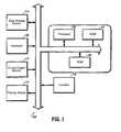
- FIG. 1is a block diagram of a system for tracking a user according to an embodiment of the present invention
- FIGS. 2(A) through 2(C)are several views of color coded visual markers used for tracking a user in an environment according to an embodiment of the present invention
- FIG. 3is a flowchart illustrating a method for detecting and decoding the color coded visual markers of FIG. 2 ;
- FIG. 4is an image of a marker showing feature correspondences and lines projected onto the image to determine edges of the four blocks of the color coded visual marker;
- FIGS. 5(A) through 5(C)are several views of black/white matrix coded visual markers used for tracking a user in an environment according to another embodiment of the present invention.
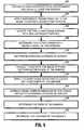
- FIG. 6is a flowchart illustrating a method for detecting and decoding the black/white matrix coded visual markers of FIG. 5 ;
- FIG. 7is an image of a marker depicting the method used to extract a corner point of the matrix coded visual marker according to the method illustrated in FIG. 6 ;
- FIG. 8is a diagram illustrating the interpolation of marker points of a black/white matrix coded visual marker in accordance with the present invention.
- the present inventionis directed to coded visual markers for tracking and camera calibration in mobile computing systems, systems employing the coded visual markers and methods for detecting and decoding the markers when in use.
- color coded visual markersare employed in systems for tracking a user and assisting the user in navigating a site or interacting with a piece of equipment.
- black and white matrix coded visual markersare utilized.
- the marker-based tracking system of the present inventionincludes a plurality of markers placed throughout a workspace or environment of a user. Each of the markers are associated with a code or label and the code is associated with either a location of the marker or an item the marker is attached to.
- the userdirects a camera, coupled to a processor, to one or more of the markers. The camera captures an image of the marker or markers and determines the code of the markers. It then uses the codes to extract information about the location of the markers or about items in the close proximity to the markers.
- the present inventionmay be implemented in various forms of hardware, software, firmware, special purpose processors, or a combination thereof.
- the present inventionmay be implemented in software as an application program tangibly embodied on a program storage device.
- the application programmay be uploaded to, and executed by, a machine comprising any suitable architecture such as that shown in FIG. 1 .
- the machine 100is implemented on a computer platform having hardware such as one or more central processing units (CPU) 102 , a random access memory (RAM) 104 , a read only memory (ROM) 106 , input/output (I/O) interface(s) such as keyboard 108 , cursor control device (e.g., a mouse) 110 , display device 112 and camera 116 for capturing video images.
- the computer platformalso includes an operating system and micro instruction code.
- the various processes and functions described hereinmay either be part of the micro instruction code or part of the application program (or a combination thereof) which is executed via the operating system.
- various other peripheral devicesmay be connected to the computer platform such as an additional data storage device 114 and a printing device.
- the machine 100is embodied in a mobile device such as a laptop computer, notebook computer, personal digital assistant (PDA), etc.
- FIGS. 2(A) through 2(C)are several views of color coded visual markers used for tracking a user in an environment according to an embodiment of the present invention.
- the color based markerswork well for relatively simple cases under friendly illuminative conditions.
- Each of these markers 202 , 204 , 206includes four square blocks of either black or color. To simplify the marker detection and color classification, the color of the color blocks is limited to be one of the three primitive colors (i.e., red, green, and blue).
- the four blocks 208 , 210 , 212 , 214are centered at the four corners points of an invisible square 216 , shown as a dashed line in FIG. 2(A) .
- To determine the orientation of a markerat least one and at most three of the four blocks of a marker are white patched 218 . If there are two white patched blocks in one marker, the two blocks are preferably next to each other (not in diagonal) to ensure that there will be no confusion in determining the orientation.
- the marker 202is coded by the colors of the four blocks 208 , 210 , 212 , 214 and the number of white patched blocks.
- the color coded visual markersuse ‘r’ for red, ‘g’ for green, ‘b’ for blue, and ‘d’ for black.
- the order of the codeis clockwise from the first white centered block 208 , which is the block at the upper-left, and will include a letter for each color of the representative block. (Note, the lower-left block is preferably not white patched and at most the marker will include three white patched blocks).
- the number at the end of the codeis the number of white patched blocks of the corresponding marker. For example, the marker shown in FIG.
- a user equipped with a mobile computer having a camera coupled to the computerwill enter a workspace or environment that has the color coded markers placed throughout.
- a video sequence of the environment including at least one markerwill be captured (step 302 ) to acquire an image of the marker.
- a watershed transformationis applied to the image to extract closed-edge strings that form the contours of the marker (step 304 ). Since the markers are using the three primitive colors for marker coding, the watershed transformation need be applied to the two color components from RGB with the lower intensities to extract the color blocks.
- step 306strings which are less than a predetermined value for representing a square block in a marker are eliminated. Then, the closed-edge strings are grouped based on the similarity of their lengths. The four strings that have the least maximum mutual distance will be put in one group (step 308 ).
- the four weight centers of the strings in each groupare used as correspondences of the centers of the four blocks of a marker to compute a first estimation of a homography from the marker model plane to the image plane (step 310 ).
- the homographyis used to project eight straight lines to form the four blocks of the marker as shown in FIG. 4 (step 312 ). These back projected lines are then used as an initialization to fit straight lines on the image plane.
- the cross points of these straight linesare taken as the first estimation of the correspondences of the corner points of the marker.
- a 1-D Canny edge detection methodas is known in the art, (in the direction perpendicular to the first estimated edges) is used to locate accurately the edge points of the square blocks (step 314 ). Then, the eight straight lines fitted from these accurate edge points are used to extract the feature correspondences, i.e., corner points, of the marker with sub-pixel accuracy. Once the corner points of the marker are extracted along with the edge points of the square blocks, the blocks of the marker can be defined and each block can be analyzed for its color.
- the average values of the red, green, and blue component(denoted as R, G, and B) of all the pixels inside the block (the white patch area excluded) are measured. Then, the intensity I, hue H, and saturation S of the averaged block color is computed as follows:
- the color of the corresponding square blockis then determined by the values of I, H, and S as follows: if I ⁇ I thr , the color is black; else, if S ⁇ S thr , the color is still black; else, if 0 ⁇ H ⁇ 2 ⁇ /3, the color is red; if 2 ⁇ /3 ⁇ H ⁇ 4 ⁇ /3, the color is green; if 4 ⁇ /3 ⁇ H ⁇ 2 ⁇ , the color is blue.
- I thr and S thrare user adjustable thresholds.
- the code for the markeris derived as described above (step 318 ), for example, drdr 1 .
- the codecan be matched against a database of codes, where the database will have information related to the code (step 320 ) and the pose of the marker can be determined.
- the informationmay include a location of the marker, a type of a piece of equipment the marker is attached to, etc.
- the color coded visual markersprovide up to 16 accurate correspondences available for calibration. Additionally, by taking the cross points of the color block, the correspondences of the four center points of the blocks can be located with higher accuracy, where four points provides the least correspondences for computing the homography resulting in faster processing.
- FIGS. 5(A) through 5(C)are several views of matrix coded visual markers used for tracking a user in an environment according to another embodiment of the present invention. Using the black/white matrix coded markers can avoid the problems caused by instability of color classification under unfriendly lighting conditions.
- a black/white matrix coded marker 502is formed by a thick rectangular frame 504 and a coding matrix 506 formed by a pattern of small black circles 508 distributed inside the inner rectangular of the marker.
- the markers shown in FIGS. 5 (A)-(C)are coded with a 4 ⁇ 4 coding matrix.
- the marker 502 with a 4 ⁇ 4 coding matrixis coded using a 12-bit binary number with each bit correspond to a numbered position in the coding matrix as shown in FIG. 5(A) .
- the 4 corner positions labeled ‘a’, ‘b’, ‘c’, and ‘d’ in the coding matrixare reserved for a determination of marker orientation. If the corresponding numbered position is covered by a small black circle, then the corresponding numbered bit of the 12-bit binary number is 1, otherwise it is 0. The marker is thus labeled by the decimal value of the 12-bit binary number.
- bis black
- chas to be also black.
- a black/white matrix coded visual marker system of an embodiment of the present inventioncan have 3 ⁇ 2 m ⁇ n ⁇ 4 markers.
- the redundant positions in the coding matrixcan be used for implementation of automatic error-bit correction to improve the robustness of the marker decoding.
- the marker shown in FIG. 5(B)is coded as 4095b (wherein the 12-bit number is 111111111111) and the marker shown in FIG. 5(C) is 1365a (e.g., 010101010101).
- a user equipped with a mobile computer having a camera coupled to the computerwill enter a workspace or environment that has the black/white matrix coded markers placed throughout.
- a video sequence of the environment including at least one markerwill be captured (step 602 ) to acquire an image of the marker.
- a watershed transformationis applied to the image to extract insulated low intensity areas and store their edges as closed-edge strings (step 604 ).
- the two closed-edge stringsare found that have very close weight centers to form a contour of the marker, i.e., d i,j ⁇ d thr , where, d i,j is the distance between the weight centers of the closed-edge strings i and j, d thr is an adjustable threshold (step 606 ).
- another condition checkcan be applied to see whether a bounding box of the shorter edge string is totally inside the bounding box of the longer edge string.
- FIG. 7shows an example of such candidate edge strings.
- the methodcan extract image points of the outer corners of a marker from the candidate edge strings (step 608 ).
- the pointsare sorted in the longer edge string to an order that all the edge points are sequential connected.
- a predetermined numbere.g., twenty, of evenly distributed edge points are selected from the edge string that evenly divide the sorted edge string into segments.
- the cross point of straight lines fitted using points 1 to 4 and points 5 to 8will be the first estimation of the image correspondence of a corner point of the marker.
- the other corner pointscan be found similarly (step 610 ).
- the estimation of the image correspondences of the marker cornercan be improved by using all the edge points of the edge string to fit the lines and find the cross points (step 612 ).
- the 1-D Canny edge detection methodis then applied to find the edge of the marker (step 614 ) and the final correspondences of the marker corners are computed. Once the marker has been detected, the image correspondences of the circles in the coding matrix need to be identified to determine the code of the marker.
- step 616There are two ways to extract the image correspondences of the circles of the matrix for decoding (step 616 ): (1) Project the marker to the image with the first estimation of a homography obtained from the correspondences of corner points c 1 ,c 2 ,c 3 and c 4 . To get accurate back projection, a non-linear optimization is needed in the estimation of the homography. (2) To avoid the non-linear optimization, an approximation of the feature points can be approximated using linear interpolation. For this purpose, the interpolation functions of the 4-node-2-dimensional linear serendipity element from finite element method, as is known in the art, can be used. Shown in FIG. 8 , the approximate image correspondence (u, v) of point (X, Y) can be obtained from:
- the 1-D Canny edge detectionis also applied to accurately locate the correspondences of the corners of the inner square.
- the code for the markeris derived as described above (step 618 ), for example, 4095 b as shown in FIG. 6(B) .
- the codecan be matched against a database of codes, where the database will have information related to the code (step 620 ) and the pose of the marker can be determined. Additionally, the centers of the black circles can be used as additional correspondences for camera calibration. For a marker using a 4 ⁇ 4 coding matrix, there can be up to 23 correspondences (i.e., the marker coded 4095 a ).
- the marker detection and decodingis based on the image intensity only. Therefore, the detection and decoding are not affected by a color classification problem, and stable decoding results can be obtained under various environments. For the purposes of detecting markers and finding correspondences, only an 8-bit gray level image is needed, resulting in processing a smaller amount of data and achieving better system performance. Additionally, the black/white matrix coded markers provide a larger number of different coded markers, resulting increased coding flexibility.
- the marker systems of the present inventioncan obtain accurate (sub-pixel) correspondences of more than 4 co-planar points using one marker or a set of markers in the same plane. Since the metric information of the feature points on the markers are known, there are two cases when the information can be used to carry out camera calibration: (i) to obtain both intrinsic and extrinsic camera parameters; (ii) pose estimation, i.e., when the intrinsic camera parameters are known, to obtain the extrinsic parameters. In the first case, a homography-based calibration algorithm can be applied. For the second case, either the homography-based algorithm or a conventional 3-point algorithm can be applied. In many cases, the camera's intrinsic parameters can be obtained using Tsai's algorithm, as is known in the art, or the homography-based algorithm.
- the coded visual markers of the present inventioncan be used in many applications, for example, for localization and data navigation.
- a useris equipped with a mobile computer that has (wireless) network connection with a main system, e.g. a server, so the user can access a related database.
- a main systeme.g. a server
- There is a camera attached to the mobile computerfor example, a SONY VAIOTM with a built-in USB camera and a built-in microphone or XybernautTM mobile computer with an plug-in USB camera and microphone.
- the systemcan help the user to locate their coordinates in large industrial environments and present to them information obtained from the database and the real-time systems.
- the usercan interact with the system using keyboard, touch pad, or even voice.
- the markers coordinates and orientation in the global systemare predetermined, the camera captures the marker and the system computes for the pose of the camera related to the captured marker, and thus obtain the position and orientation of the camera in the global system.
- Such localization informationis then used for accessing related external databases, for example, to obtain the closest view of an on-site image with a 3-D reconstructed virtual structure overlay, or present the internal design parameters of a piece of equipment of interest. Additionally, the localization information can also be used to navigate the user through the site.
- a head mounted-displayis a key component to create an immersive AR environment for the users, i.e., an environment where virtual objects are combined with real objects.
- HMDhead mounted-display
- the optical-see-through HMDdirectly uses a scene of the real world with the superimposition of virtual objects projected to the eye using a projector attached to eyeglasses. Since the real-world is directly captured by the eye, it usually requires the calibration of the HMD with the user's eyes to obtain good registration between the virtual objects and the real world.
- the video-see-throughuses a pair of cameras to capture the scenes of the real-world which is projected to the user.
- the superimposition of virtual objectsis performed on the captured images. Therefore, only the camera needs to be calibrated for such AR processes.
- the coded markers described aboveare suitable for motion tracking and calibration in the HMD applications for both industrial and medical applications.
Landscapes
- Engineering & Computer Science (AREA)
- Computer Vision & Pattern Recognition (AREA)
- Physics & Mathematics (AREA)
- General Physics & Mathematics (AREA)
- Theoretical Computer Science (AREA)
- Multimedia (AREA)
- Length Measuring Devices By Optical Means (AREA)
Abstract
Description
dmax:=max(S(di,j)) (1)
where, 1≦i≦N, 1≦j≦N, and i≠j,di,jis the distance between the weight center of string i and the weight center of string j; S represent the set of di,jfor all eligible i and j. The four weight centers of the strings in each group are used as correspondences of the centers of the four blocks of a marker to compute a first estimation of a homography from the marker model plane to the image plane (step310). The homography is used to project eight straight lines to form the four blocks of the marker as shown in
di,j≦dthr,
where, di,jis the distance between the weight centers of the closed-edge strings i and j, dthris an adjustable threshold (step606). An additional condition for the two closed-edge strings to be a candidate of a marker contour is
if 1i<1j, then clower1j≦1i≦
else clower1i≦1j≦
where 1iand 1jare the lengths (in number of edge points) of the edge strings, clowerand cupperthe coefficients for the lower and upper limit of the string length. For example, when the width of the inner square is 0.65 times of the width of the outer square, clower=0.5 and cupper=0.8 can be chosen. In addition, another condition check can be applied to see whether a bounding box of the shorter edge string is totally inside the bounding box of the longer edge string.
where the interpolation function Ni(X,Y) is expressed as
for i=1, 2, 3, and 4.
Claims (12)
Priority Applications (1)
| Application Number | Priority Date | Filing Date | Title |
|---|---|---|---|
| US11/704,137US7809194B2 (en) | 2001-10-04 | 2007-02-08 | Coded visual markers for tracking and camera calibration in mobile computing systems |
Applications Claiming Priority (3)
| Application Number | Priority Date | Filing Date | Title |
|---|---|---|---|
| US32696001P | 2001-10-04 | 2001-10-04 | |
| US10/262,693US20030076980A1 (en) | 2001-10-04 | 2002-10-02 | Coded visual markers for tracking and camera calibration in mobile computing systems |
| US11/704,137US7809194B2 (en) | 2001-10-04 | 2007-02-08 | Coded visual markers for tracking and camera calibration in mobile computing systems |
Related Parent Applications (1)
| Application Number | Title | Priority Date | Filing Date |
|---|---|---|---|
| US10/262,693DivisionUS20030076980A1 (en) | 2001-10-04 | 2002-10-02 | Coded visual markers for tracking and camera calibration in mobile computing systems |
Publications (2)
| Publication Number | Publication Date |
|---|---|
| US20070133841A1 US20070133841A1 (en) | 2007-06-14 |
| US7809194B2true US7809194B2 (en) | 2010-10-05 |
Family
ID=26949399
Family Applications (2)
| Application Number | Title | Priority Date | Filing Date |
|---|---|---|---|
| US10/262,693AbandonedUS20030076980A1 (en) | 2001-10-04 | 2002-10-02 | Coded visual markers for tracking and camera calibration in mobile computing systems |
| US11/704,137Expired - Fee RelatedUS7809194B2 (en) | 2001-10-04 | 2007-02-08 | Coded visual markers for tracking and camera calibration in mobile computing systems |
Family Applications Before (1)
| Application Number | Title | Priority Date | Filing Date |
|---|---|---|---|
| US10/262,693AbandonedUS20030076980A1 (en) | 2001-10-04 | 2002-10-02 | Coded visual markers for tracking and camera calibration in mobile computing systems |
Country Status (1)
| Country | Link |
|---|---|
| US (2) | US20030076980A1 (en) |
Cited By (14)
| Publication number | Priority date | Publication date | Assignee | Title |
|---|---|---|---|---|
| US20140321747A1 (en)* | 2013-04-28 | 2014-10-30 | Tencent Technology (Shenzhen) Co., Ltd. | Method, apparatus and terminal for detecting image stability |
| US9424651B2 (en) | 2014-04-07 | 2016-08-23 | Samsung Electronics Co., Ltd. | Method of tracking marker and electronic device thereof |
| US9519968B2 (en) | 2012-12-13 | 2016-12-13 | Hewlett-Packard Development Company, L.P. | Calibrating visual sensors using homography operators |
| US9561019B2 (en) | 2012-03-07 | 2017-02-07 | Ziteo, Inc. | Methods and systems for tracking and guiding sensors and instruments |
| US20170174440A1 (en)* | 2015-12-16 | 2017-06-22 | Waste Repurposing International, Inc. | Household Hazardous Waste Recovery |
| US9760804B2 (en)* | 2007-01-23 | 2017-09-12 | Nec Corporation | Marker generating and marker detecting system, method and program |
| US9980666B2 (en) | 2013-02-15 | 2018-05-29 | Koninklijke Philips N. V. | System and method for determining a vital sign of a subject |
| US10242456B2 (en) | 2011-06-23 | 2019-03-26 | Limitless Computing, Inc. | Digitally encoded marker-based augmented reality (AR) |
| US10241616B2 (en) | 2014-02-28 | 2019-03-26 | Hewlett-Packard Development Company, L.P. | Calibration of sensors and projector |
| US10449572B2 (en) | 2015-12-16 | 2019-10-22 | Waste Repurposing International, Inc. | Household hazardous waste recovery |
| US10617401B2 (en) | 2014-11-14 | 2020-04-14 | Ziteo, Inc. | Systems for localization of targets inside a body |
| US11439358B2 (en) | 2019-04-09 | 2022-09-13 | Ziteo, Inc. | Methods and systems for high performance and versatile molecular imaging |
| US11468598B2 (en)* | 2018-04-27 | 2022-10-11 | Shanghai Truthvision Information Technology Co., Ltd. | System and method for camera calibration |
| US11915097B1 (en) | 2020-01-14 | 2024-02-27 | Apple Inc. | Visual marker with user selectable appearance |
Families Citing this family (60)
| Publication number | Priority date | Publication date | Assignee | Title |
|---|---|---|---|---|
| US6985612B2 (en)* | 2001-10-05 | 2006-01-10 | Mevis - Centrum Fur Medizinische Diagnosesysteme Und Visualisierung Gmbh | Computer system and a method for segmentation of a digital image |
| US20030218638A1 (en)* | 2002-02-06 | 2003-11-27 | Stuart Goose | Mobile multimodal user interface combining 3D graphics, location-sensitive speech interaction and tracking technologies |
| US7343278B2 (en)* | 2002-10-22 | 2008-03-11 | Artoolworks, Inc. | Tracking a surface in a 3-dimensional scene using natural visual features of the surface |
| FR2857131A1 (en)* | 2003-07-01 | 2005-01-07 | Thomson Licensing Sa | METHOD FOR AUTOMATICALLY REPLACING A GEOMETRIC MODEL OF A SCENE ON A PICTURE OF THE SCENE, DEVICE FOR IMPLEMENTING THE SAME, AND PROGRAMMING MEDIUM |
| JP4401727B2 (en)* | 2003-09-30 | 2010-01-20 | キヤノン株式会社 | Image display apparatus and method |
| WO2005103616A1 (en)* | 2004-04-27 | 2005-11-03 | Gennady Anatolievich Gienko | Method for stereoscopically measuring image points and device for carrying out said method |
| DE102005005242A1 (en)* | 2005-02-01 | 2006-08-10 | Volkswagen Ag | Camera offset determining method for motor vehicle`s augmented reality system, involves determining offset of camera position and orientation of camera marker in framework from camera table-position and orientation in framework |
| AU2006225115B2 (en)* | 2005-03-16 | 2011-10-06 | Lucasfilm Entertainment Company Ltd. | Three- dimensional motion capture |
| WO2007030026A1 (en) | 2005-09-09 | 2007-03-15 | Industrial Research Limited | A 3d scene scanner and a position and orientation system |
| US20090002224A1 (en)* | 2005-09-22 | 2009-01-01 | Nader Khatib | SAR ATR tree line extended operating condition |
| US7697827B2 (en) | 2005-10-17 | 2010-04-13 | Konicek Jeffrey C | User-friendlier interfaces for a camera |
| CA2566260C (en)* | 2005-10-31 | 2013-10-01 | National Research Council Of Canada | Marker and method for detecting said marker |
| JP5084167B2 (en)* | 2006-03-31 | 2012-11-28 | キヤノン株式会社 | Position and orientation measurement method and apparatus |
| KR100844129B1 (en)* | 2006-09-13 | 2008-07-04 | 한국전자통신연구원 | Mouse interface device using camera, system and method by the device, and computer readable recording medium for realizing this |
| US20080170750A1 (en)* | 2006-11-01 | 2008-07-17 | Demian Gordon | Segment tracking in motion picture |
| WO2008073563A1 (en)* | 2006-12-08 | 2008-06-19 | Nbc Universal, Inc. | Method and system for gaze estimation |
| US8542236B2 (en)* | 2007-01-16 | 2013-09-24 | Lucasfilm Entertainment Company Ltd. | Generating animation libraries |
| US8130225B2 (en) | 2007-01-16 | 2012-03-06 | Lucasfilm Entertainment Company Ltd. | Using animation libraries for object identification |
| US8199152B2 (en) | 2007-01-16 | 2012-06-12 | Lucasfilm Entertainment Company Ltd. | Combining multiple session content for animation libraries |
| US20080291272A1 (en)* | 2007-05-22 | 2008-11-27 | Nils Oliver Krahnstoever | Method and system for remote estimation of motion parameters |
| US8558893B1 (en) | 2007-08-03 | 2013-10-15 | Sprint Communications Company L.P. | Head-up security display |
| US8355961B1 (en) | 2007-08-03 | 2013-01-15 | Sprint Communications Company L.P. | Distribution center head-up display |
| US20090290753A1 (en)* | 2007-10-11 | 2009-11-26 | General Electric Company | Method and system for gaze estimation |
| US8055296B1 (en) | 2007-11-06 | 2011-11-08 | Sprint Communications Company L.P. | Head-up display communication system and method |
| US8264422B1 (en) | 2007-11-08 | 2012-09-11 | Sprint Communications Company L.P. | Safe head-up display of information |
| US8144153B1 (en) | 2007-11-20 | 2012-03-27 | Lucasfilm Entertainment Company Ltd. | Model production for animation libraries |
| US7850067B1 (en)* | 2007-11-27 | 2010-12-14 | Sprint Communications Company L.P. | Color bar codes |
| US8254635B2 (en)* | 2007-12-06 | 2012-08-28 | Gideon Stein | Bundling of driver assistance systems |
| EP2157545A1 (en)* | 2008-08-19 | 2010-02-24 | Sony Computer Entertainment Europe Limited | Entertainment device, system and method |
| US9142024B2 (en)* | 2008-12-31 | 2015-09-22 | Lucasfilm Entertainment Company Ltd. | Visual and physical motion sensing for three-dimensional motion capture |
| CN101650828B (en)* | 2009-09-07 | 2012-03-07 | 东南大学 | Method for reducing random error of round object location in camera calibration |
| US9158777B2 (en) | 2010-03-30 | 2015-10-13 | Gravity Jack, Inc. | Augmented reality methods and apparatus |
| JP4971483B2 (en) | 2010-05-14 | 2012-07-11 | 任天堂株式会社 | Image display program, image display apparatus, image display system, and image display method |
| EP2395474A3 (en)* | 2010-06-11 | 2014-03-26 | Nintendo Co., Ltd. | Storage medium having image recognition program stored therein, image recognition apparatus, image recognition system, and image recognition method |
| US9013550B2 (en)* | 2010-09-09 | 2015-04-21 | Qualcomm Incorporated | Online reference generation and tracking for multi-user augmented reality |
| US8818132B2 (en)* | 2010-11-29 | 2014-08-26 | Microsoft Corporation | Camera calibration with lens distortion from low-rank textures |
| JP5178860B2 (en)* | 2011-02-24 | 2013-04-10 | 任天堂株式会社 | Image recognition program, image recognition apparatus, image recognition system, and image recognition method |
| US8817046B2 (en)* | 2011-04-21 | 2014-08-26 | Microsoft Corporation | Color channels and optical markers |
| US8948447B2 (en) | 2011-07-12 | 2015-02-03 | Lucasfilm Entertainment Companyy, Ltd. | Scale independent tracking pattern |
| US20130050499A1 (en)* | 2011-08-30 | 2013-02-28 | Qualcomm Incorporated | Indirect tracking |
| WO2013074926A1 (en) | 2011-11-18 | 2013-05-23 | Lucasfilm Entertainment Company Ltd. | Path and speed based character control |
| GB201122284D0 (en)* | 2011-12-23 | 2012-02-01 | Zappar Ltd | Content identification and distribution |
| US9338447B1 (en)* | 2012-03-14 | 2016-05-10 | Amazon Technologies, Inc. | Calibrating devices by selecting images having a target having fiducial features |
| US8970709B2 (en)* | 2013-03-13 | 2015-03-03 | Electronic Scripting Products, Inc. | Reduced homography for recovery of pose parameters of an optical apparatus producing image data with structural uncertainty |
| US9852512B2 (en) | 2013-03-13 | 2017-12-26 | Electronic Scripting Products, Inc. | Reduced homography based on structural redundancy of conditioned motion |
| CN103218820B (en)* | 2013-04-22 | 2016-02-10 | 苏州科技学院 | A kind of camera calibration error compensating method based on multidimensional characteristic |
| US10363486B2 (en) | 2013-06-10 | 2019-07-30 | Pixel Press Technology, LLC | Smart video game board system and methods |
| US9579573B2 (en)* | 2013-06-10 | 2017-02-28 | Pixel Press Technology, LLC | Systems and methods for creating a playable video game from a three-dimensional model |
| JP5812550B1 (en)* | 2014-10-10 | 2015-11-17 | ビーコア株式会社 | Image display device, image display method, and program |
| CN104680535A (en)* | 2015-03-06 | 2015-06-03 | 南京大学 | Calibration target, calibration system and calibration method for binocular direct-looking camera |
| US10403019B2 (en)* | 2015-12-16 | 2019-09-03 | Lucasfilm Entertainment Company | Multi-channel tracking pattern |
| US11007014B2 (en)* | 2015-12-18 | 2021-05-18 | Koninklijke Philips N.V. | Medical instrument tracking |
| US11577159B2 (en) | 2016-05-26 | 2023-02-14 | Electronic Scripting Products Inc. | Realistic virtual/augmented/mixed reality viewing and interactions |
| ES2616146B2 (en)* | 2016-12-20 | 2018-04-27 | Universitat D'alacant / Universidad De Alicante | METHOD OF DETECTION AND RECOGNITION OF LONG REACH AND HIGH DENSITY VISUAL MARKERS |
| WO2020159553A1 (en)* | 2019-02-01 | 2020-08-06 | Hewlett-Packard Development Company, L.P. | Three-dimensional camera pose determination |
| CN111457914B (en)* | 2020-01-22 | 2022-11-25 | 南京航空航天大学 | Multi-rudder wing dynamic swing angle measuring method based on encodable visual cooperation target |
| CN113240744B (en)* | 2020-01-23 | 2024-10-11 | 华为技术有限公司 | Image processing method and device |
| CN111833405B (en)* | 2020-07-27 | 2023-12-08 | 北京大华旺达科技有限公司 | Calibration and identification method and device based on machine vision |
| CN113298213B (en)* | 2021-06-03 | 2023-12-22 | 杭州三坛医疗科技有限公司 | Label, label detection method and device, visual reference system, device and medium |
| CN116128976B (en)* | 2023-02-02 | 2025-07-18 | 郑州大学 | A positioning method and decoding method of temporal visual landmarks based on RGB |
Citations (3)
| Publication number | Priority date | Publication date | Assignee | Title |
|---|---|---|---|---|
| US5856844A (en)* | 1995-09-21 | 1999-01-05 | Omniplanar, Inc. | Method and apparatus for determining position and orientation |
| US6782119B1 (en)* | 2000-06-29 | 2004-08-24 | Ernest Ross Barlett | Space planning system |
| US7526122B2 (en)* | 2001-07-12 | 2009-04-28 | Sony Corporation | Information inputting/specifying method and information inputting/specifying device |
- 2002
- 2002-10-02USUS10/262,693patent/US20030076980A1/ennot_activeAbandoned
- 2007
- 2007-02-08USUS11/704,137patent/US7809194B2/ennot_activeExpired - Fee Related
Patent Citations (3)
| Publication number | Priority date | Publication date | Assignee | Title |
|---|---|---|---|---|
| US5856844A (en)* | 1995-09-21 | 1999-01-05 | Omniplanar, Inc. | Method and apparatus for determining position and orientation |
| US6782119B1 (en)* | 2000-06-29 | 2004-08-24 | Ernest Ross Barlett | Space planning system |
| US7526122B2 (en)* | 2001-07-12 | 2009-04-28 | Sony Corporation | Information inputting/specifying method and information inputting/specifying device |
Cited By (26)
| Publication number | Priority date | Publication date | Assignee | Title |
|---|---|---|---|---|
| US9760804B2 (en)* | 2007-01-23 | 2017-09-12 | Nec Corporation | Marker generating and marker detecting system, method and program |
| US10242456B2 (en) | 2011-06-23 | 2019-03-26 | Limitless Computing, Inc. | Digitally encoded marker-based augmented reality (AR) |
| US10489930B2 (en) | 2011-06-23 | 2019-11-26 | Limitless Computing, Inc. | Digitally encoded marker-based augmented reality (AR) |
| US11080885B2 (en) | 2011-06-23 | 2021-08-03 | Limitless Computing, Inc. | Digitally encoded marker-based augmented reality (AR) |
| US10426350B2 (en) | 2012-03-07 | 2019-10-01 | Ziteo, Inc. | Methods and systems for tracking and guiding sensors and instruments |
| US9561019B2 (en) | 2012-03-07 | 2017-02-07 | Ziteo, Inc. | Methods and systems for tracking and guiding sensors and instruments |
| US11678804B2 (en) | 2012-03-07 | 2023-06-20 | Ziteo, Inc. | Methods and systems for tracking and guiding sensors and instruments |
| US9519968B2 (en) | 2012-12-13 | 2016-12-13 | Hewlett-Packard Development Company, L.P. | Calibrating visual sensors using homography operators |
| US9980666B2 (en) | 2013-02-15 | 2018-05-29 | Koninklijke Philips N. V. | System and method for determining a vital sign of a subject |
| US20140321747A1 (en)* | 2013-04-28 | 2014-10-30 | Tencent Technology (Shenzhen) Co., Ltd. | Method, apparatus and terminal for detecting image stability |
| US9317770B2 (en)* | 2013-04-28 | 2016-04-19 | Tencent Technology (Shenzhen) Co., Ltd. | Method, apparatus and terminal for detecting image stability |
| US10241616B2 (en) | 2014-02-28 | 2019-03-26 | Hewlett-Packard Development Company, L.P. | Calibration of sensors and projector |
| US9424651B2 (en) | 2014-04-07 | 2016-08-23 | Samsung Electronics Co., Ltd. | Method of tracking marker and electronic device thereof |
| US11464503B2 (en) | 2014-11-14 | 2022-10-11 | Ziteo, Inc. | Methods and systems for localization of targets inside a body |
| US10617401B2 (en) | 2014-11-14 | 2020-04-14 | Ziteo, Inc. | Systems for localization of targets inside a body |
| US12239301B2 (en) | 2014-11-14 | 2025-03-04 | Ziteo, Inc. | Methods and systems for localization of targets inside a body |
| US10449572B2 (en) | 2015-12-16 | 2019-10-22 | Waste Repurposing International, Inc. | Household hazardous waste recovery |
| US10118199B2 (en) | 2015-12-16 | 2018-11-06 | Waste Repurposing International, Inc. | Waste recovery systems and methods |
| US9707595B2 (en)* | 2015-12-16 | 2017-07-18 | Waste Repurposing International, Inc. | Household hazardous waste recovery |
| US20170174440A1 (en)* | 2015-12-16 | 2017-06-22 | Waste Repurposing International, Inc. | Household Hazardous Waste Recovery |
| US11468598B2 (en)* | 2018-04-27 | 2022-10-11 | Shanghai Truthvision Information Technology Co., Ltd. | System and method for camera calibration |
| US11439358B2 (en) | 2019-04-09 | 2022-09-13 | Ziteo, Inc. | Methods and systems for high performance and versatile molecular imaging |
| US11883214B2 (en) | 2019-04-09 | 2024-01-30 | Ziteo, Inc. | Methods and systems for high performance and versatile molecular imaging |
| US12329551B2 (en) | 2019-04-09 | 2025-06-17 | Ziteo, Inc. | Methods and systems for high performance and versatile molecular imaging |
| US11915097B1 (en) | 2020-01-14 | 2024-02-27 | Apple Inc. | Visual marker with user selectable appearance |
| US12333378B1 (en) | 2020-01-14 | 2025-06-17 | Apple Inc. | Visual marker with user selectable appearance |
Also Published As
| Publication number | Publication date |
|---|---|
| US20070133841A1 (en) | 2007-06-14 |
| US20030076980A1 (en) | 2003-04-24 |
Similar Documents
| Publication | Publication Date | Title |
|---|---|---|
| US7809194B2 (en) | Coded visual markers for tracking and camera calibration in mobile computing systems | |
| US8335400B2 (en) | Information processing method and information processing apparatus | |
| CN106372702B (en) | Positioning identifier and positioning method thereof | |
| JP5905540B2 (en) | Method for providing a descriptor as at least one feature of an image and method for matching features | |
| US6417836B1 (en) | Computer input device having six degrees of freedom for controlling movement of a three-dimensional object | |
| US8605987B2 (en) | Object-based 3-dimensional stereo information generation apparatus and method, and interactive system using the same | |
| US6925122B2 (en) | Method for video-based nose location tracking and hands-free computer input devices based thereon | |
| CN108388341B (en) | Man-machine interaction system and device based on infrared camera-visible light projector | |
| CN115885314B (en) | Image processing method, device, equipment and storage medium | |
| CN113240656B (en) | Visual positioning method and related device and equipment | |
| CN108022265A (en) | Infrared camera pose determines method, equipment and system | |
| JP2003178303A (en) | Object recognition device | |
| WO2023193763A1 (en) | Data processing method and apparatus, and tracking mark, electronic device and storage medium | |
| Cho et al. | Fast color fiducial detection and dynamic workspace extension in video see-through self-tracking augmented reality | |
| KR20010055957A (en) | Image Registration Method Using 3D Tracker And Computer Vision For Augmented Reality | |
| US10635958B2 (en) | Hybrid visual tagging using customized colored tiles | |
| US6304672B1 (en) | Edge detecting method and edge detecting device which detects edges for each individual primary color and employs individual color weighting coefficients | |
| López-Nicolás et al. | Spatial layout recovery from a single omnidirectional image and its matching-free sequential propagation | |
| Wang et al. | ReLoc: indoor visual localization with hierarchical sitemap and view synthesis | |
| KR100702534B1 (en) | ID Judgment Method Using Expandable Visual Marker with Direction Information | |
| Schall et al. | 3D tracking in unknown environments using on-line keypoint learning for mobile augmented reality | |
| CN111739086A (en) | Method and device for measuring area, electronic device and storage medium | |
| CN117274397A (en) | Camera calibration method for augmented reality technology | |
| Bradley et al. | Natural interaction with virtual objects using vision-based six DOF sphere tracking | |
| Velipasalar et al. | Recovering field of view lines by using projective invariants |
Legal Events
| Date | Code | Title | Description |
|---|---|---|---|
| AS | Assignment | Owner name:SIEMENS CORPORATE RESEARCH, INC.,NEW JERSEY Free format text:ASSIGNMENT OF ASSIGNORS INTEREST;ASSIGNORS:ZHANG, XIANG;NAVAB, NASSIR;REEL/FRAME:024579/0773 Effective date:20021202 Owner name:SIEMENS CORPORATION,NEW JERSEY Free format text:MERGER;ASSIGNOR:SIEMENS CORPORATE RESEARCH, INC.;REEL/FRAME:024579/0805 Effective date:20090902 Owner name:SIEMENS CORPORATE RESEARCH, INC., NEW JERSEY Free format text:ASSIGNMENT OF ASSIGNORS INTEREST;ASSIGNORS:ZHANG, XIANG;NAVAB, NASSIR;REEL/FRAME:024579/0773 Effective date:20021202 Owner name:SIEMENS CORPORATION, NEW JERSEY Free format text:MERGER;ASSIGNOR:SIEMENS CORPORATE RESEARCH, INC.;REEL/FRAME:024579/0805 Effective date:20090902 | |
| STCF | Information on status: patent grant | Free format text:PATENTED CASE | |
| FPAY | Fee payment | Year of fee payment:4 | |
| MAFP | Maintenance fee payment | Free format text:PAYMENT OF MAINTENANCE FEE, 8TH YEAR, LARGE ENTITY (ORIGINAL EVENT CODE: M1552) Year of fee payment:8 | |
| FEPP | Fee payment procedure | Free format text:MAINTENANCE FEE REMINDER MAILED (ORIGINAL EVENT CODE: REM.); ENTITY STATUS OF PATENT OWNER: LARGE ENTITY | |
| AS | Assignment | Owner name:SIEMENS MEDICAL SOLUTIONS USA, INC., PENNSYLVANIA Free format text:ASSIGNMENT OF ASSIGNORS INTEREST;ASSIGNOR:SIEMENS CORPORATION;REEL/FRAME:060213/0895 Effective date:20220615 | |
| LAPS | Lapse for failure to pay maintenance fees | Free format text:PATENT EXPIRED FOR FAILURE TO PAY MAINTENANCE FEES (ORIGINAL EVENT CODE: EXP.); ENTITY STATUS OF PATENT OWNER: LARGE ENTITY | |
| STCH | Information on status: patent discontinuation | Free format text:PATENT EXPIRED DUE TO NONPAYMENT OF MAINTENANCE FEES UNDER 37 CFR 1.362 | |
| FP | Lapsed due to failure to pay maintenance fee | Effective date:20221005 |