US7809074B2 - Generalized reference signaling scheme for multi-user, multiple input, multiple output (MU-MIMO) using arbitrarily precoded reference signals - Google Patents
Generalized reference signaling scheme for multi-user, multiple input, multiple output (MU-MIMO) using arbitrarily precoded reference signalsDownload PDFInfo
- Publication number
- US7809074B2 US7809074B2US11/687,508US68750807AUS7809074B2US 7809074 B2US7809074 B2US 7809074B2US 68750807 AUS68750807 AUS 68750807AUS 7809074 B2US7809074 B2US 7809074B2
- Authority
- US
- United States
- Prior art keywords
- transmit beamforming
- receiving device
- matrix
- vector
- vectors
- Prior art date
- Legal status (The legal status is an assumption and is not a legal conclusion. Google has not performed a legal analysis and makes no representation as to the accuracy of the status listed.)
- Active, expires
Links
- 230000011664signalingEffects0.000titleclaimsdescription29
- 239000013598vectorSubstances0.000claimsabstractdescription295
- 239000011159matrix materialSubstances0.000claimsabstractdescription216
- 238000012360testing methodMethods0.000claimsabstractdescription80
- 238000000926separation methodMethods0.000claimsabstractdescription18
- 238000000034methodMethods0.000claimsdescription88
- 230000005540biological transmissionEffects0.000claimsdescription78
- 238000013461designMethods0.000claimsdescription42
- 238000004422calculation algorithmMethods0.000claimsdescription30
- 239000000284extractSubstances0.000claimsdescription8
- 238000009499grossingMethods0.000claimsdescription5
- 230000006870functionEffects0.000description23
- 238000004891communicationMethods0.000description21
- 230000008569processEffects0.000description14
- 230000008901benefitEffects0.000description12
- 238000012545processingMethods0.000description12
- 238000000605extractionMethods0.000description8
- 230000000694effectsEffects0.000description6
- 238000013139quantizationMethods0.000description5
- 238000001228spectrumMethods0.000description4
- 238000013459approachMethods0.000description3
- 230000003044adaptive effectEffects0.000description2
- 238000004364calculation methodMethods0.000description2
- 238000000354decomposition reactionMethods0.000description2
- 238000005516engineering processMethods0.000description2
- 230000001965increasing effectEffects0.000description2
- 230000007246mechanismEffects0.000description2
- 230000008054signal transmissionEffects0.000description2
- 238000012549trainingMethods0.000description2
- 239000000654additiveSubstances0.000description1
- 230000000996additive effectEffects0.000description1
- 230000004075alterationEffects0.000description1
- 238000003491arrayMethods0.000description1
- 230000001413cellular effectEffects0.000description1
- 230000008859changeEffects0.000description1
- 238000004590computer programMethods0.000description1
- 230000021615conjugationEffects0.000description1
- 238000001514detection methodMethods0.000description1
- 238000011161developmentMethods0.000description1
- 238000010586diagramMethods0.000description1
- 230000002708enhancing effectEffects0.000description1
- 238000011156evaluationMethods0.000description1
- 230000010365information processingEffects0.000description1
- 230000007774longtermEffects0.000description1
- 238000012986modificationMethods0.000description1
- 230000004048modificationEffects0.000description1
- 230000010363phase shiftEffects0.000description1
- 230000004044responseEffects0.000description1
- 230000035945sensitivityEffects0.000description1
- 230000003595spectral effectEffects0.000description1
- 238000000528statistical testMethods0.000description1
- 239000000126substanceSubstances0.000description1
- 238000006467substitution reactionMethods0.000description1
Images


Classifications
- H—ELECTRICITY
- H04—ELECTRIC COMMUNICATION TECHNIQUE
- H04B—TRANSMISSION
- H04B7/00—Radio transmission systems, i.e. using radiation field
- H04B7/02—Diversity systems; Multi-antenna system, i.e. transmission or reception using multiple antennas
- H04B7/04—Diversity systems; Multi-antenna system, i.e. transmission or reception using multiple antennas using two or more spaced independent antennas
- H04B7/0413—MIMO systems
- H04B7/0456—Selection of precoding matrices or codebooks, e.g. using matrices antenna weighting
- H—ELECTRICITY
- H04—ELECTRIC COMMUNICATION TECHNIQUE
- H04B—TRANSMISSION
- H04B7/00—Radio transmission systems, i.e. using radiation field
- H04B7/02—Diversity systems; Multi-antenna system, i.e. transmission or reception using multiple antennas
- H04B7/04—Diversity systems; Multi-antenna system, i.e. transmission or reception using multiple antennas using two or more spaced independent antennas
- H04B7/0413—MIMO systems
- H—ELECTRICITY
- H04—ELECTRIC COMMUNICATION TECHNIQUE
- H04B—TRANSMISSION
- H04B7/00—Radio transmission systems, i.e. using radiation field
- H04B7/02—Diversity systems; Multi-antenna system, i.e. transmission or reception using multiple antennas
- H04B7/04—Diversity systems; Multi-antenna system, i.e. transmission or reception using multiple antennas using two or more spaced independent antennas
- H04B7/06—Diversity systems; Multi-antenna system, i.e. transmission or reception using multiple antennas using two or more spaced independent antennas at the transmitting station
- H04B7/0613—Diversity systems; Multi-antenna system, i.e. transmission or reception using multiple antennas using two or more spaced independent antennas at the transmitting station using simultaneous transmission
- H04B7/0615—Diversity systems; Multi-antenna system, i.e. transmission or reception using multiple antennas using two or more spaced independent antennas at the transmitting station using simultaneous transmission of weighted versions of same signal
- H04B7/0665—Feed forward of transmit weights to the receiver
- H—ELECTRICITY
- H04—ELECTRIC COMMUNICATION TECHNIQUE
- H04L—TRANSMISSION OF DIGITAL INFORMATION, e.g. TELEGRAPHIC COMMUNICATION
- H04L25/00—Baseband systems
- H04L25/02—Details ; arrangements for supplying electrical power along data transmission lines
- H04L25/03—Shaping networks in transmitter or receiver, e.g. adaptive shaping networks
- H04L25/03006—Arrangements for removing intersymbol interference
- H04L25/03343—Arrangements at the transmitter end
- H—ELECTRICITY
- H04—ELECTRIC COMMUNICATION TECHNIQUE
- H04L—TRANSMISSION OF DIGITAL INFORMATION, e.g. TELEGRAPHIC COMMUNICATION
- H04L25/00—Baseband systems
- H04L25/02—Details ; arrangements for supplying electrical power along data transmission lines
- H04L25/03—Shaping networks in transmitter or receiver, e.g. adaptive shaping networks
- H04L25/03006—Arrangements for removing intersymbol interference
- H04L2025/0335—Arrangements for removing intersymbol interference characterised by the type of transmission
- H04L2025/03426—Arrangements for removing intersymbol interference characterised by the type of transmission transmission using multiple-input and multiple-output channels
- H—ELECTRICITY
- H04—ELECTRIC COMMUNICATION TECHNIQUE
- H04W—WIRELESS COMMUNICATION NETWORKS
- H04W48/00—Access restriction; Network selection; Access point selection
- H04W48/16—Discovering, processing access restriction or access information
Definitions
- the present inventionis directed in general to the field of information processing.
- the present inventionrelates to a system and method for communicating reference signal information in wireless multiple input, multiple output (MIMO) communication systems.
- MIMOmultiple input, multiple output
- Wireless communication systemstransmit and receive signals within a designated electromagnetic frequency spectrum, but the capacity of the electromagnetic frequency spectrum is limited.
- MIMOMultiple Input Multiple Output
- MIMOMultiple Input Multiple Output
- SDMAspace division multiple access
- SDMA based methodshave been adopted in several current emerging standards such as IEEE 802.16 and the 3rd Generation Partnership Project (3GPP) Long Term Evolution (LTE) platform.
- FIG. 1depicts a wireless MIMO communication system 100 that employs SDMA.
- transmitters and receiversare both equipped with multiple antennas.
- the wireless communication system 100includes one or more transmitters 101 (e.g., base stations) and one or more receiver stations 102 . 1 - 102 . m (e.g., subscriber stations), where “m” is an integer representing the number of receiver stations in a given geographic area.
- Base stations and subscriber stationscan be both transmitters and receivers when both base stations and subscriber stations are equipped with a receiver and a transmitter.
- Base stationsgenerally communicate with multiple subscriber stations. Subscriber stations communicate directly with a base station and indirectly, via the base station, with other subscriber stations.
- the number of base stationsdepends in part on the geographic area to be served by the wireless communication system 100 .
- Subscriber systemscan be virtually any type of wireless one-way or two-way communication device such as a cellular telephones, wireless equipped computer systems, and wireless personal digital assistants.
- the signals communicated between base stations and subscriber stationscan include voice, data, electronic mail, video, and other data, voice, and video signals.
- each base station 101 and subscriber station 102 . iincludes an array of antennas for transmitting and receiving signals.
- different subscriber stationsshare the same time-frequency channel and the separation between them occurs in the spatial dimension.
- the antenna arrayforms a beam or multiple beams by applying a set of transmit beam forming weights to signals applied to each antenna in the antenna array.
- a different set of transmit beam forming weightsis applied by the base station to each communication with each subscriber station with a goal of minimizing interference between the radio communication devices signals.
- TDDtime division duplex
- FDDfrequency division duplex
- beam forming between the base station and subscriber stationsallows the allocation of the same time channel and different frequency channel to subscriber stations during downlink and uplink.
- the MIMO system base station 101uses beamforming to transmit a single data stream (e.g., s 1 ) through multiple antennas, and the receiver combines the received signal from the multiple receive antennas to reconstruct the transmitted data.
- Thisis accomplished with “beamforming” weights whereby a signal s i is processed in a signal processing unit 103 . i for transmission by applying a weight vector w i to the signal s i and transmitting the result x i over an array of antennas.
- the weighting vector w iis used to direct the signal with the objective of enhancing the signal quality or performance metric, like signal-to-interference-and-noise ratio (SINR) of the received signal.
- SINRsignal-to-interference-and-noise ratio
- the received signals detected by the array of antennasare processed using a combining vector v i .
- the base station 101has an array of N antennas 105 , where N is an integer greater than or equal to m.
- the base stationprepares a transmission signal, represented by the vector x i , for each signal s i , where i ⁇ 1, 2, . . . , m ⁇ . (Note: lower case bold variables indicate vectors and upper case BOLD variables indicate matrices).
- the term “s i ”is the data to be transmitted to the i th receiver.
- Each of the coefficients of weight vector w imay be a complex weight.
- transmission beamforming vectorsare referred to as “weight vectors,” and reception vectors are referred to as “combining vectors,” though in systems having reciprocal channels (such as TDD systems), a combining vector v at a receiver/subscriber station can be used as both a combining vector (when receiving signals from a transmitter/base station) and a weighting vector (when transmitting to a transmitter/base station).
- the transmission signal vector x iis transmitted via a channel represented by a channel matrix H i .
- the channel matrix H irepresents a channel gain between the transmitter antenna array 105 and the receive antenna array 104 . i at the i th subscriber station 102 . i .
- the channel matrix H ican be represented by a N ⁇ k i matrix of complex coefficients, where N is the number of antennas at the base station antenna array 105 and k i is the number of antennas in the i th subscriber station antenna array 104 . i .
- the value of k ican be unique for each subscriber station.
- the channel matrix H ican instead be represented by a k i ⁇ N matrix of complex coefficients, in which case the matrix manipulation algorithms are adjusted accordingly so that, for example, the right singular vector calculation on a N ⁇ k i channel matrix becomes a left singular vector calculation on a k i ⁇ N channel matrix.
- the coefficients of the channel matrix H idepend, at least in part, on the transmission characteristics of the medium, such as air, through which a signal is transmitted.
- a variety of methodsmay be used to determine the channel matrix H i coefficients, such as transmitting a known pilot signal to a receiver so that the receiver, knowing the pilot signal, can estimate the coefficients of the channel matrix H i using well-known pilot estimation techniques.
- the actual channel matrix H iis known to the receiver and may also be known to the transmitter.
- the transmitted signalsare received on the k i receive antennas.
- the received signals for the i th subscriber station 102 . iare represented by a k i ⁇ 1 received signal vector y i in accordance with Equation [2]:
- s iis the data to be transmitted to the i th subscriber station 102 .
- s nis the data transmitted to the n th subscriber station 102 .
- the * superscriptdenotes the complex conjugation operator
- H i Hrepresents the complex conjugate transpose of the channel matrix correlating the base station 101 and i th subscriber station 102 .
- Equation [2]The first term on the right hand side of Equation [2] is the desired receive signal while the summation terms less the desired receive signal represent co-channel interference.
- CSITchannel-side information at the transmitter
- precoding techniquescan be used at the base station 101 to provide a multi-mode beamformer function to optimally match the input signal on one side to the channel on the other side so that multiple users or subscriber stations can be simultaneously scheduled on the same time-frequency resource block (RB) by separating them in the spatial dimension.
- Thisis referred to as a space division multiple access (SDMA) system or as a multi-user (MU)-MIMO system.
- Additional examples of precodinginclude using a channel quality indicator (CQI) value measured at a receiver 102 . i to perform adaptive modulation and coding (AMC) on the transmit signal before transmission to the receiver 102 . i.
- CQIchannel quality indicator
- AMCadaptive modulation and coding
- While full broadband channel knowledgemay be obtained at the transmitter 101 by using uplink sounding techniques (e.g., with Time Division Duplexing (TDD) systems), most precoded MIMO systems (e.g., with TDD or Frequency Division Duplexing (FDD) systems) use channel feedback techniques to measure channel information at the receiver 102 . i and then feed back the measured channel information to the transmitter 101 .
- TDDTime Division Duplexing
- FDDFrequency Division Duplexing
- SINRSINR
- CQIchannel quality information
- the incomplete knowledge at a receiverresults from the fact that signal information being sent to other receivers can appear as interference or noise at the intended receiver 102 .
- the signaling overhead associated with feeding forward the precoding matrix information to each receiver stationcan be quite large, especially when the precoding matrix information can be arbitrarily computed as a function of the channel vector feedback information from each receiver station.
- Dedicated reference signalscan be used whereby one or more reference signals are weighted and transmitted using the same transmit beamforming vectors as the beamformed data signals.
- dedicated reference signalstypically require a significant signaling overhead for notifying each receiver of its dedicated reference signal, such as control signals to indicate the number of precoded streams and the desired reference signal for each receiver. Even if the signaling overhead is included as part of the usual scheduling overhead, it still consumes valuable overhead.
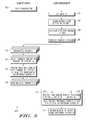
- FIG. 1(labeled prior art) depicts a wireless communication system
- FIG. 2depicts a wireless communication system in which precoded reference signals are fed forward to convey downlink transmit beamforming matrix information to each receiver station;
- FIG. 3depicts a first example flow for a precoding methodology for generating and feeding forward precoded reference signal information to one or more user equipment devices;
- FIG. 4depicts an example flow for a generalized reference signaling scheme for a multi-user MIMO system using arbitrarily precoded reference signals
- FIG. 5depicts an example flow for a generalized reference signaling scheme for a multi-user MIMO system using a single precoded reference signal.
- a reference signal feed forward system and methodologyare described for use in efficiently providing precoding matrix information to receivers in a wireless, multi-user, multi-input, multiple output (MIMO) SDMA system.
- a transmittere.g., base station
- precoded reference signalsare fed forward to some or all of the receivers (e.g., user equipment devices) to provide knowledge of the precoding vectors to the receiver(s).
- Dedicated precoded reference signalsare used whereby one or more reference signals are weighted and transmitted using the same transmit beamforming vectors as the beamformed data signals.
- the precoded reference signalsare processed with one or more hypothesis tests to extract the beamforming vectors and/or matrix information which enables receive beamformers to be designed for the receiver, such as by using, for example, a minimum mean square error (MMSE) criterion.
- MMSEminimum mean square error
- a first testis performed at the receiver to process the precoded reference signals to detect which of the precoded reference signals was intended for the receiver in question without the need of feed forwarding explicit information to that effect.
- a generalized reference signaling schemeis enabled for a MU-MIMO system using arbitrarily precoded reference signals.
- FIG. 2depicts a wireless communication system 200 in which N precoded reference signal(s) 216 are fed forward from a transmitter 210 (e.g., a base station) to one or more receivers 201 . 1 through 201 . m (e.g., subscriber stations) to convey downlink transmit beamforming matrix information to each receiver station 201 . i .
- the transmitter 210includes an array 226 of antennas for communicating with the receivers 201 . 1 through 201 . m , each of which includes an array 202 . i of receive antennas for communicating with the transmitter 210 .
- a data signal s i presented at the transmitter 210 for transmission to the receiver 201 . iis transformed by the signal processor 224 .
- the channel matrix H imay be represented as an N ⁇ k i matrix of complex entries representing the complex coefficients of the transmission channel between each transmit-receive antenna pair, where N represents the number of transmit antennas in the transmit antenna array 226 , and k i represents the number of antennas of the i th receiver 201 . i (or vice versa).
- the signal processing unit 203 . iprocesses the y i signals received on the k antennas to obtain a data signal, z i , which is an estimate of the transmitted data signal s i .
- the processing of the received y i signalsmay include combining the y i signals with appropriate combining vector information v i generated by the minimum mean square error (MMSE) receiver design module 209 . i .
- the receiver 201 . iuses the precoded reference signals to extract the transmit beamforming vector matrix information W generated at the transmitter 210 , and then uses the extracted transmit beamforming vector matrix information W to compute or choose the combining vector information v, using any desired receive beamformer design method, for example the MMSE method.
- Transmit beamforming or precoding at the transmittermay be implemented by having each receiver 201 . i determine its MIMO channel matrix H i —which specifies the transmission channel between a transmitter and an i th receiver—in the channel estimation signal processing unit 203 . i .
- each receiver 201 . 1 through 201 . mdetermines its MIMO channel matrix H i by using pilot estimation or sounding techniques to determine or estimate the coefficients of the channel matrix H i .
- Each receiver 201.
- a receive beamforming design module 204 . i at each receiver 201 . icomputes an initial or optimal receive beamforming vector v opt i that represents an optimal blind receive beamforming vector, such as by maximizing a predetermined receive signal-to-interference-and-noise (SINR) metric.
- SINRreceive signal-to-interference-and-noise
- the initial beamforming vector v opt iis used to generate effective channel information in the design module 204 . i , such as by computing or selecting a vector codeword u, representing the vector quantity H v opt i .
- the vector codeword u irepresents the preferred precoding vector for the receiver 201 . i , where the preferred precoding vector are the columns of on or more unitary matrices, which may be referred to as basis vectors.
- each receiver 201 . imay compute and feed back other information in addition to, or in place of effective channel information u i , such as channel quality information (CQI) or any other information that may be used at the transmitter to generate precoding matrix W information.
- CQIchannel quality information
- a feedback codebook 211 . i at the receiver 201 . imay be used to store an indexed set of possible codewords u so that the codewords u generated by the vector design module 204 .
- ican be used by the quantizer 205 . i to retrieve a corresponding index from the feedback codebook 211 . i and provide the retrieved index over a feedback channel 218 . i (e.g., a low rate feedback channel 215 ) to the transmitter 210 .
- a feedback channel 218 . ie.g., a low rate feedback channel 215
- the transmitter 210decodes or dequantizes the indexed feedback information using a codebook-based dequantizer 220 which accesses a feedback codebook 221 to obtain the effective channel information (e.g., u i ) for the receiver 201 . i .
- the transmitter feedback codebook 221is the same as the feedback codebook 211 . i used at the receiver 201 . i .
- the retrieved effective channel informationis provided to the design module 222 which computes scheduling information and designs the transmit beamforming vectors w i for each receiver 201 . i
- Equation 4is a typical spatial separation constraints equation that ensures that the desired signal component is accentuated and the undesirable interference terms are minimized at the receiver.
- the designed precoding vectors w iare computed as a function of the preferred precoding vectors requested by the receivers.
- the design module 222can use any (arbitrary) multi-user MIMO algorithm to generate the beamforming matrix information W 223 .
- the designed transmit beamforming vectorsare selected from a defined set of candidate transmit beamforming vectors which are also known to the receivers 201 . i , even though any given receiver has no advance knowledge about which transmit beamforming vector is intended for which receiver.
- the design module 222designs the transmit beamforming vectors w i for each receiver 201 . i , the design module 222 provides the designed transmit beamforming vectors w i contained in the precoding information 223 to one or more signal processors 224 . i where they are applied to precode the data input signal s i in the course of generating the transmit signal x i which is transmitted over the transmit antenna array 226 to the receiver(s) 201 . i.
- the beamforming matrix Wis used by the encoder module 225 in the reference signal generator 228 to generate up to N precoded reference signal(s) 216 that may be fed forward to the receivers 201 . i .
- the precoded reference signalsmay refer to one or more (up to N) precoded reference signals, depending on how the transmit beamforming matrix is encoded and received.
- the transmitter 210transmits one or more precoded reference signals corresponding to either the transmit beamforming matrix or to one or more of its computed transmit beamforming vectors. For example, if the transmitter antenna array 226 has four transmit antennas, up to four receivers can be simultaneously supported when zero-forcing beamforming is used.
- up to four reference signalsare precoded with precoding vectors (e.g., w 1 , w 2 , w 3 , and w 4 ), thereby generating up to four precoded reference signals (e.g., RS 1 w 1 , RS 2 w 2 , RS 3 w 3 , and RS 4 w 4 ).
- the beamforming matrix Wis fed forward to each receiver 201 . i by sending bits 216 on the control channel that are indicative of the transmission matrix used.
- This approachassumes that the transmission matrix W is chosen from a set of M possible candidate matrices so that each candidate matrix may be uniquely identified by a minimum of log 2 (M) bits.
- a feed forward codebook 227may be used to store each of the candidate matrices with their corresponding bit index values.
- the bit index that is representative of the transmission matrix Wmay be transmitted by the transmitter to each receiving device. And since the receiving device has information of all possible candidate transmission matrices beforehand (e.g., stored in a feed forward codebook 212 .
- the receiving devicecan use the bit index to retrieve the appropriate transmission matrix W by a single lookup, and can subsequently use this transmission matrix W to design its receive beamformer.
- a bit sequence uniquely identifying the transmission matrix W aboveis transmitted and the receiver retrieves the transmission matrix W by employing a lookup into its database of candidate transmission matrices.
- the transmitter and the receivercan share beforehand a codebook of transmission vectors, and the final transmission matrix W used would be a combination of at most N distinct transmission vectors.
- the transmittermay signal the transmission matrix W by sending N K-bit sequences, where each sequence is uniquely representative of the transmission vectors comprising the transmission matrix W, where K is the minimum number of bits required to uniquely represent each candidate transmission vector.
- the transmittermay sent N bit sequences, each of which uniquely identifies the codewords that were fed back to the transmitter by each multiplexed user, where K is the minimum number of bits required to uniquely represent each candidate transmission vector.
- the transmitteruses a pre-determined algorithm, which is known to all receiving units, to map the codewords to the final transmission matrix W used.
- the receiverfirst retrieves the codewords of all multiplexed users using the bit sequences fed forward to it by the transmitter, and then constructs the transmission matrix W using the known algorithm. The result of the execution of either of the embodiments above is the knowledge of the transmission matrix W at the receiver.
- the receiving unitexecutes a second test to determine which of the transmission vectors contained in W is meant for it.
- the precoded reference signals (RS 1 w 1 , RS 2 w 2 , . . . RS M w M ) 216may be fed forward by the feed forward control field generator 229 over a feed forward channel 219 . i (e.g., a low rate feed forward channel 215 ) to the receivers 201 . i .
- a feed forward control decoder(not shown) is used to decode the feed forward signal to obtain the precoded reference signal information generated by the transmitter 210 .
- the retrieved precoded reference signal informationis processed by the beamforming matrix estimation module 206 . i to enable MMSE receive operations without having prior knowledge about which specific precoding vector w UE was intended for the receiver or which beamforming algorithm was used by the transmitter 210 to generate the precoding vectors w 1 , w 2 , . . . w m .
- the transmitter 210has complete flexibility in designing its beamforming matrix and precoding algorithms.
- the beamforming matrix estimator 206 . iprocesses the received precoded reference signals to detect which exact precoding vectors w 1 , w 2 , . . . w m were used by the transmitter 210 , and to detect which of the precoding vectors is intended for the receiver in question.
- the beamforming matrix estimator 206 . iperforms hypothesis testing on the received precoded reference signals.
- the extraction module 207 . idetermines which reference signal, out of the ‘m’ reference signals transmitted, is encoded using the transmission vector intended for the receiver by effectively projecting the received precoded reference signals to its optimal blind receive beamformer.
- the comparison functionuses the received precoded reference signals to determine which reference signal is intended for the receiver.
- the detection functionapplies the following test:
- v optis the optimal blind receive beamformer initially designed by the receiver design module 204 .
- the desired reference signal chosenis the one that maximizes the test defined in Equation [6]. In effect, this test provides a measure of how “aligned” each precoding vector is with respect to the users effective channels. As a result, the precoded reference signals can be fed forward to the receivers without also feeding forward explicit information to identify which precoding vector was intended for the receiver.
- the beamforming matrix estimator 206 . imay also perform additional hypothesis testing on the received precoded reference signals to extract the precoding matrix W used by the transmitter to facilitate MMSE decoding at the receiver.
- the extraction module 208 . iapplies a second hypothesis test to extract from a predetermined set the exact precoding vector used to generate each precoding reference signal, thereby obtaining information of all precoded vectors generated by the transmitter.
- the extraction functiontests each precoded reference signal to identify which precoding vector from a predetermined set of precoding vectors was used to generate the precoded reference signal.
- this testprovides a distance measure that is used to identify which precoding vector (e.g., w 1 , w 2 , . . . w m ) is the beamforming vector w used to generate the precoded reference signal.
- the beamforming matrix estimatorUpon extracting the complete set of precoding vectors (which may be represented as a precoding matrix W), the beamforming matrix estimator provides this information to the MMSE receiver design module 209 . i which computes the adjusted combining vector v for the receiver 201 . i .
- the adjusted combining vector v iis used by the receiver signal processing unit 203 . i to process the y i signals received on the k antennas to obtain a data signal, z i by combining the y i signals with the adjusted combining vector information v i .
- the transmission vector to receiver i, w imay be chosen by the base station such that it can potentially be any vector in the N dimensional complex space—in such a case the test in Equation [7] cannot be applied since the set of possible precoding vectors is unknown at the receiver.
- the following procedureis used to design the receive beamformer.
- MMSE receive beamformerdetermines which of the N reference signals is meant for itself. For example, we can assume that a receiver 201 . i determines that the y 1 reference signal is intended for the receiver 201 . i . Once the intended reference signal is detected, the MMSE receive beamformer is then designed using the following function:
- Iis the identity matrix
- ⁇ n 2is the white noise spectral density.
- the receive beamformermay be designed using the following function:
- FIG. 3depicts a generalized example flow for a precoding methodology 300 for generating and feeding forward precoded reference signal information to one or more user equipment devices.
- the MIMO transmission channel to a given receiver stationis estimated by transmitting a pilot signal from the transmitter or base station (step 302 ) to the receiver or user equipment where the transmission channel is estimated (step 304 ).
- a transmission channelcan be estimated by embedding a set of predetermined symbols, known as training symbols, at a base station and processing the training symbols at the user equipment to produce a set of initial channel estimates.
- the MIMO transmission channel being estimated at the user equipmentmay be characterized as a channel matrix H.
- the user equipmentalso uses the channel estimate information H to compute the effective channel vector information (step 308 ), such as by computing or selecting a codeword u.
- the receive beamforming vector v and codeword umay be computed in a variety of different ways.
- Q(.)is some quantization function.
- the codeword uis indexed and fed back to the base station at step 310 .
- codebook-based feedback indexing techniquesmay be used to quantize the codeword u where the base station and user equipment share the same feedback codebook.
- the feedback information from the user equipmentis dequantized (step 312 ) into the effective channel vector information (e.g., codeword u).
- the dequantized effective channel vector informationis used by the base station to design the transmit beamforming vectors w i using any arbitrary multi-user MIMO beamforming algorithm (step 314 ), such as a regularized ZFBF algorithm.
- the dequantized effective channel vector informationmay also be used to select an appropriate modulation and coding level in systems that implement adaptive modulation and coding (AMC) mechanisms.
- AMCadaptive modulation and coding
- the base stationuses the vectors w i to compute precoded reference signals (step 316 ), such as by precoding one or more reference signals with the transmit beamforming vectors w i .
- the base stationuses the vectors w i to derive the bit index values corresponding to the precoding matrix W formed from the vectors w i .
- the precoded reference signals(or the index bit values) are then fed forward to the user equipment as part of the downlink data transmission (step 318 ), either directly or in quantized form using a feedforward codebook.
- the feed forward informationis decoded to obtain the precoded reference signals.
- the base station and user equipment device(s)share the same feed forward codebook.
- the precoded reference signalsare tested to obtain the information needed to perform MMSE receive operations (step 320 ).
- the testingconsists of one or more hypothesis tests which take into account the presence of Gaussian noise at the receiver. As a result, the robustness of the testing is directly a function of the additive noise present and interference present.
- a first testis used to extract the precoding vector w from the precoded reference signals that is intended for the user equipment in question, but without requiring that explicit information be fed forward to specify the intended precoding vector.
- the intended reference signalis identified from the precoded reference signals by selecting the precoding vector from a finite set of precoding vectors (e.g., w 1 , w 2 , w 3 , w 4 ) which minimizes the distance measure,
- the first extraction test 322uses properties of zero-forcing type beamforming techniques whereby, with the optimal receive beamformer v opt used, the other precoding vectors will be substantially orthogonal to the equivalent channel H v opt .
- the testing of the precoded reference signalsmay also include a second test (step 324 ) which extracts the precoding matrix W from the precoded reference signals by extracting from each precoded reference signal the precoding vector w i that was used to precode the precoded reference signal, again without requiring that explicit information be fed forward specifying the precoding matrix W.
- the precoding matrix Wis extracted from the precoded reference signals by selecting the precoding vector from a predetermined set of precoding vectors (e.g., w 1 , w 2 , . . . w m ) which minimizes the distance measure, min i ⁇ y ⁇ H H w i ⁇ 2 .
- the extracted precoding vector informationis used by the user equipment to design the receive beamforming vectors v i for the user equipment (step 326 ), such as by using an MMSE receiver to derive the receive beamforming vectors v i .
- FIG. 4depicts an example flow 400 for a generalized reference signaling scheme for a multi-user MIMO system using arbitrarily precoded reference signals.
- the vectors u and vmay be jointly designed by selecting candidate values from a codebook of indexed precoding parameters that maximize a predetermined performance metric for estimating the receive SINR, where the metric is defined to reduce quantization errors resulting from the codebook-based selection process.
- the receiver stationuses the computed vector v as an initial receive beamforming vector.
- the indexed effective channel informationis then communicated as a feedback signal over the feedback control channel to the transmitter station (step 406 ) and the receiver repeats the foregoing sequence during the next design cycle (as indicated by the feedback line to step 402 ).
- the feedback signals from the receiver stationsare decoded to generate effective channel information for each receiver station, and this information is used to design transmit beamformers w 1 , w 2 , . . . w m using any arbitrary multi-user MIMO technique (step 408 ), such as zero-forcing beamforming.
- the N precoded reference signalsare tested to detect the transmit beamformer that was intended for receiver, and to extract all transmit beamformers generated by the transmitter (step 412 ).
- the precoding vector w UE intended for the user equipment receiveris detected by selecting a vector from a finite set of predetermined precoding vectors that maximizes the objective function
- v optis the optimal blind receive beamformer initially designed by the receiver
- His the channel matrix to the receiver in question.
- the receiveruses the extracted information to design the receive beamformer v i for the MMSE receiver (step 414 ), and the receiver then uses the designed receive beamformer v i to receive OFDM symbol subcarriers that were encoded with transmit beamformer w i for the receiver (step 416 ).
- each receiveris able to extract the transmit precoding vector information from the precoded reference signals without having received prior knowledge of the specific precoding and beamforming algorithm used by the transmitter, either by choosing from a predefined set of precoding vectors (e.g., w 1 , w 2 , . . . w m ) that is stored at each receiver, or by estimating the precoding vectors instead of doing a hypothesis test if they are arbitrary (i.e., they do not come from a pre-defined set but instead are derived from an arbitrary continuous space).
- predefined set of precoding vectorse.g., w 1 , w 2 , . . . w m
- selected embodiments of the present inventionprovide for an even more efficient reference signaling scheme for multi-user MIMO systems by using structured precoded reference signals in combination with regularized zero-forcing beamforming techniques to effectively convey the transmit precoding matrix W with a minimum of a single precoded reference signal.
- a mechanismis disclosed by which information regarding an N ⁇ N transmission matrix (for any N) can be fed forward to each receiver by using just one precoded reference signal.
- complete knowledge of the beamforming matrixmay be provided to each receiver, but is done in such a way that size of the feed forward information does not scale with the size of N.
- the reliability or robustness of this algorithmcan be improved by adding more reference signals which is illustrated later on.
- the transmitter base station 210 with multiple transmit antennas 226communicates in a multi-user MIMO mode with multiple user equipment receivers 201 . 1 - 201 . m , each of which has a multi-antenna array 202 . i .
- the transmitter base station 210transmits via beamforming so that the signal, denoted by s i , transmitted to a given user equipment receiver 201 . i provides no interference to other receivers in the system.
- the transmitterchooses the appropriate transmit beamformers w i based on the downlink channel information u i that has been fed back by each receiver over a feed back channel 218 . i .
- Downlink channel estimationis done at each receiver 201 . i and is quantized using a known feedback codebook 211 . i so that a codeword is selected from the codebook 211 . i and fed back to the transmitter 210 . Due to the imperfect channel knowledge at the transmitter 210 , each receiver 201 . i encounters interference from the transmissions to the other receivers in spite of the transmitter's effort to separate the multi-user streams.
- the vector design module 222uses a predetermined MU-MIMO algorithm—which in one embodiment can be a regularized zero-forcing beamforming (R-ZFBF) algorithm—to obtain user separation.
- R-ZFBFregularized zero-forcing beamforming
- the ‘m’ receiversfeed back equivalent channel vectors (denoted as u 1 , u 2 , . . . , u m ) from this set U.
- WX[X H X+ ⁇ I] ⁇ 1 , where I is an identity matrix and ⁇ is a scalar constant that provides a smoothing function to regularize the imperfection in effective channel estimates due to quantization or otherwise.
- Iis an identity matrix
- ⁇is a scalar constant that provides a smoothing function to regularize the imperfection in effective channel estimates due to quantization or otherwise.
- the columns of the actual beamforming matrix Ware further normalized to be of unit norm.
- the optimal receiver/combiner at a receiver 201 . iis an MMSE receiver which obtains knowledge of the beamforming matrix W by receiving a single precoded reference signal on the forward downlink channel prior to data transmission using the compact feed forward scheme described herein.
- the approachexploits the fact that the precoding matrix W corresponding to each unique combination of the possible codewords u i is unique. Since each possible precoding matrix W is unique, the codewords in each possible X can be arranged by ordered indices so that the precoded reference signal or pilot that is sent on the downlink broadcast channel uses a single predetermined column of the designed beamforming matrix W (e.g., the first column, or the second column, or the third column, etc.).
- the extraction module 208 . i in each receiver station 201 . idetermines the precoding matrix W by hypothesis testing the precoded reference signal against the predetermined column (e.g., the first column) of all possible W S (which are predetermined and locally stored). As can be seen, the extraction module 207 . i (described above with reference to the multi-reference signal embodiment) is not needed to detect which precoding matrix W is signified by the single precoded reference signal.
- the transmitter 210uses the requested codeword u i that was fed back as the transmit codeword c i for a given receiver 201 . i .
- two scenariosmay arise.
- the first scenarioif the transmitter 210 does not use the codeword u i requested by a given receiver 201 . i and instead uses a different transmit codeword c i , then the receiver 201 . i searches over all possible W S .
- the search spacemay be further reduced by eliminating one or more highly improbable combinations.
- the selected precoding matrix Wis the estimate of the transmit beamforming matrix used by the transmitter 210 , and is used by the MMSE receiver 209 . i in the receiver 201 . i to design the receive beamforming vectors v i .
- each of the possible transmission matricesmay be associated with a unique vector from a feed forward vector codebook.
- the reference signalmay be encoded with the vector representative of the transmission matrix used.
- the test in Equation [10]is modified to test the reference signal over all possible vector codewords in the feed forward codebook (in lieu of searching over the first columns) with the objective of identifying the codeword used for precoding. Once the codeword is identified, the transmission matrix that it uniquely represents becomes known to the receiver.
- FIG. 5depicts an example flow 500 for a generalized reference signaling scheme for a multi-user MIMO system.
- the codeword uis the transmit beamformer w requested by the receiver.
- the vectors u and vmay be jointly designed by selecting candidate values from a codebook of indexed precoding parameters that maximize a predetermined performance metric for estimating the receive SINR, where the metric is defined to reduce quantization errors resulting from the codebook-based selection process.
- the receiver stationuses the computed vector v as an initial receive beamforming vector.
- the indexed effective channel informationis then communicated as a feedback signal over the feedback control channel to the transmitter station (step 506 ) and the receiver repeats the foregoing sequence during the next design cycle (as indicated by the feedback line to step 502 ).
- the feedback signals from the receiver stationsare decoded to generate effective channel information for each receiver station, and this information is used to design transmit beamformers w 1 , w 2 , . . . w m that will separate the receivers by using a regularized zero-forcing beamforming (R-ZFBF) algorithm (step 508 ).
- R-ZFBFregularized zero-forcing beamforming
- the designed transmit beamformerstaken together, are a transmit beamforming matrix W.
- the transmitterthen feeds forward to the receivers a single precoded reference or pilot signal that is encoded using the predetermined (first, second, third, etc. . . . ) column of the designed transmit beamforming matrix W (step 510 ), either directly or using a bit-level signaling scheme.
- yis the received precoded reference signal
- His the MIMO downlink channel matrix
- W S (:,1)is the space of the predetermined columns of all W S .
- a feed forward vector codebookmay be used instead of the first column—that is a codebook/set of vectors may be defined such that each transmission matrix is uniquely defined by a distinct vector in the set.
- the reference signalingmay then be done using the codebook vector representative of the transmission matrix used, and the test above may be modified to search over all vector codewords in this codebook.
- the transmit beamforming matrix W corresponding to the selected vector w t that minimizes the test functionis the receiver's estimate of the beamforming matrix.
- This estimate of the transmit beamforming matrix Wis used by the MMSE receiver 209 . i in the receiver 201 . i to design the receive beamforming vectors v i . (step 514 ), and the receiver then uses the designed receive beamformer v i to receive data that were encoded with transmit beamformer w i for the receiver (step 516 ).
- a second testinvolves detecting which of the columns of W constitutes the beamforming vector for the receiving device. This information is required to design the MMSE receiver 209 . i , and can be obtained by identifying the column that maximizes the metric, max j
- the j that maximizes the above functionis the column of the transmission matrix that is the beamforming vector intended for itself.
- a transmitting devicee.g., a base station
- receives effective channel informationsuch as a preferred precoding vector or information representative thereof, that is fed back from each of a plurality of receiving devices (e.g., user equipment devices).
- the transmitting deviceuses the received effective channel information to generate transmit beamforming vectors, such as by using a spatial separation algorithm, such as zero-forcing beamforming, to output transmit beamforming vectors.
- Transmit beamforming vectorsmay be generated by selecting transmit beamforming vectors from a defined set of transmit beamforming vectors.
- the transmit beamforming vectorsare used to generate precoded reference signals by using each transmit beamforming vector to encode a reference signal.
- a first reference signalmay be encoded with a first transmit beamforming vector to generate a first precoded reference signal that is designed for a first receiving device
- a second reference signalmay be encoded with a second transmit beamforming vector to generate a second precoded reference signal that is designed for a second receiving device.
- the precoded reference signalsmay then be fed forward to a plurality of receiving devices where the precoded reference signals are received and used in generating receive beamforming vectors at each receiving device, where each receiving device extracts the plurality of transmit beamforming vectors from the precoded reference signals and identifies which transmit beamforming vector is designed for said receiving device without requiring additional information to be fed forward that identifies the transmit beamforming vector or precoded reference signal that is designed for said receiving device.
- the extractionmay be implemented by applying a first test to the precoded reference signals received at a receiving device to identify which transmit beamforming vector is designed for said receiving device, where the first test selects a reference signal from a finite set of transmit reference signals y j which maximizes a first projection measure
- the extractionmay be implemented by applying a second test to the precoded reference signals received at a receiving device to identify the plurality of transmit beamforming vectors generated by the transmitting device, where the second test selects, for each precoded reference signal, a transmit beamforming vector from a finite set of transmit beamforming vectors w i which minimizes a second distance measure ⁇ y ⁇ H H w i ⁇ 2 , where y is a precoded reference signal and H is a channel matrix to said receiving device.
- the plurality of transmit beamforming vectorsare extracted by selecting transmit beamforming vectors from a defined set of transmit beamforming vectors.
- the transmitting devicemay use the transmit beamforming vectors as weighting vectors for signals transmitted by the transmitting device to the at least one of the plurality of receiving device.
- a reference signaling framework and methodologyare disclosed for feeding forward references signals representing transmission matrix information formed with an arbitrary algorithm that maps codewords fed back by the users to the actual transmission matrix, where the reference signals are generated using N precoded pilots which are formed using N transmission vectors selected from an arbitrary set of vectors unknown to the receiving device.
- the N precoded pilots or reference signalsare formed by encoding N reference signals using the transmission vectors to the N users, the N reference signals are tested at each receiving device in order to infer which of the N reference signals is meant for the receiving device in question. Once detected, the receiver uses the N reference signals and the reference signal designed for the receiver to design the receiver beamformer.
- a forward reference signaling method and system for a MIMO SDMA systemthat uses a minimum of one precoded reference signal to convey transmit beamforming information.
- the designed transmit beamforming matrixis used to generate one or more precoded reference signals by using all or part of the designed transmit beamforming matrix to encode one or more reference signals.
- a precoded reference signalmay be generated by encoding a first reference pilot with a predetermined column of the transmit beamforming matrix.
- a precoded reference signalmay be generated by encoding a first reference pilot with a first vector b selected from a predetermined set of vectors, where each vector in the predetermined set of vectors uniquely represents a candidate transmit beamforming matrix.
- each transmit beamforming matrixmay be constructed as a plurality of columns arranged in a predetermined order that is known to the transmitting device and the plurality of receiving devices.
- each transmit beamforming matrixmay be uniquely associated with one or more unique identifying vectors from a feedforward vector codebook, where each unique identifying vector is generated with a Grassmanian-type codebook.
- each unique identifying vector associated with a transmission beamforming matrixmay be a predetermined column from the transmission beamforming matrix.
- the unique identifying vector which is associated with all or part of the designed transmit beamforming matrixmay be used to encode a first reference pilot, thereby generating a precoded reference signal.
- the receivercan extract the transmit beamforming matrix by hypothesis testing the received precoded reference signal against a predetermined set of vectors, where each vector in the predetermined set of vectors uniquely represents a candidate transmit beamforming matrix.
- the precoded reference signalAfter the precoded reference signal is generated by the transmitter, it is fed forward to the receiving devices for use in generating receive beamforming vectors at each receiving device, where each receiving device extracts the transmit beamforming matrix from at least the precoded reference signal and identifies a transmit beamforming vector that is designed for said receiving device without requiring additional information to be fed forward that identifies the transmit beamforming vector that is designed for said receiving device.
- the designed transmit beamforming matrixcan be extracted by hypothesis testing the received precoded reference signal against all possible candidate transmit beamforming matrices, or alternatively by hypothesis testing the received precoded reference signal against a subset of all possible candidate transmit beamforming matrices when a transmit beamforming vector for the receiving device is determined by the effective channel information fed back to the transmitting device.
- the receiving deviceIn addition to extracting the designed transmit beamforming matrix from the precoded reference signal(s), the receiving device also uses the precoded reference signal(s) to identify a column from the designed transmit beamforming matrix that is designed for the receiving device by testing all columns of the generated transmit beamforming matrix, such as by selecting a reference signal from a finite set of transmit reference signals y j which maximizes a first objective measure
- a single precoded reference signalcan be used at the receiving device to extract the designed transmit beamforming matrix.
- a plurality of precoded reference signalscan be used at the receiving device to extract the designed transmit beamforming matrix.
- a receiving devicefeeds back to a transmitting device a preferred precoding vector or information representative thereof. Based at least in part on the preferred precoding vector or information representative thereof, the transmitting device generates a transmit beamforming matrix using a spatial separation algorithm, such as zero-forcing beamforming, and then transmits over a feed forward channel one or more index bits representative of the generated transmit beamforming matrix. Using the index bits, the receiving device retrieves the generated transmit beamforming matrix from a finite set of candidate transmit beamforming matrices, and uses the transmit beamforming matrix to generate a receive beamforming vector at the receiving device.
- a spatial separation algorithmsuch as zero-forcing beamforming
- the transmitting device and receiving deviceshare a feed forward codebook containing the finite set of candidate transmit beamforming matrices.
- a reference signaling framework and methodologyare disclosed for feeding forward transmission matrix information using bits that are representative of the transmission matrix used.
- the index bit valuesare evaluated against a candidate set of transmission matrices that are generated as a set of all possible combinations of precoding vectors or codewords, wherein any precoding vector (codeword) could be used for the receiving device independent of its feedback.
- the receivercan evaluate the index bit values against a candidate set of transmission matrices that are generated as a set of all possible combinations of precoding vectors (codewords) wherein one of the precoding vector (codeword) is fixed to be the one that is fed back by the receiving device.
- the candidate set of transmission matricesmay be compressed to remove unlikely matrices.
- the methods and systems for using precoded reference signals to efficiently providing precoding matrix information to receivers in a wireless, multi-user, multi-input, multiple output (MIMO) SDMA system as shown and described hereinmay be implemented in whole or in part with software stored on a computer-readable medium and executed as a computer program on a general purpose or special purpose computer to perform certain tasks.
- MIMOmulti-input, multiple output
- the elements used to perform various signal processing steps at the transmittermay be implemented within one or more application specific integrated circuits (ASICs), digital signal processors (DSPs), digital signal processing devices (DSPDs), programmable logic devices (PLDs), field programmable gate arrays (FPGAs), processors, controllers, micro-controllers, microprocessors, other electronic units designed to perform the functions described herein, or a combination thereof.
- ASICsapplication specific integrated circuits
- DSPsdigital signal processors
- DSPDsdigital signal processing devices
- PLDsprogrammable logic devices
- FPGAsfield programmable gate arrays
- processorscontrollers, micro-controllers, microprocessors, other electronic units designed to perform the functions described herein, or a combination thereof.
- a software implementationmay be used, whereby some or all of the signal processing steps at each of the transmitter and receiver may be implemented with modules (e.g., procedures, functions, and so on) that perform the functions described herein. It will be appreciated that the separation of functionality into modules is for illustrative purposes, and alternative embodiments may merge the functionality of multiple software modules into a single module or may impose an alternate decomposition of functionality of modules.
- the software codemay be executed by a processor or controller, with the code and any underlying or processed data being stored in any machine-readable or computer-readable storage medium, such as an on-board or external memory unit.
Landscapes
- Engineering & Computer Science (AREA)
- Computer Networks & Wireless Communication (AREA)
- Signal Processing (AREA)
- Power Engineering (AREA)
- Mobile Radio Communication Systems (AREA)
- Radio Transmission System (AREA)
Abstract
Description
xi=wi·si [1]
where wi, is the ithbeamforming, N dimensional transmission weight vector (also referred to as a “transmit beamformer”), and each coefficient wjof weight vector wirepresents a weight and phase shift on the jthtransmit
where “si” is the data to be transmitted to the ithsubscriber station102.i, “sn” is the data transmitted to the nthsubscriber station102.n, the * superscript denotes the complex conjugation operator, “HiH” represents the complex conjugate transpose of the channel matrix correlating the
zi=ŝi=yiHvi. [3]
{tilde over (w)}iHuj≧γ1, if i=j
{tilde over (w)}iHuj≦γ2, if i≠j [4]
where γ1>0 and γ2are constants such that γ2<<γ1. Usually, γ2≈0. Equation 4 is a typical spatial separation constraints equation that ensures that the desired signal component is accentuated and the undesirable interference terms are minimized at the receiver. A specific embodiment of the above is the zero-forcing beamforming equation where γ1=1 and γ2=0.
{tilde over (W)}=X(XHX+αI)−1 [5]
where X=[u1u2. . . uk], I is an identity matrix and α is a scalar constant that provides a smoothing function to account for imperfections in the knowledge of the effective channel due to quantization or otherwise. The solution in Equation (5) is exact with respect to Equation (4) if α=0. This ensures that interference to a user due to the other users' transmissions is close to zero. In selected embodiments, the designed precoding vectors wiare computed as a function of the preferred precoding vectors requested by the receivers. However, while zero-forcing beamforming can be used to generate a beamforming matrix W=[w1, w2, . . . wm]223, it will be appreciated that the
where voptis the optimal blind receive beamformer initially designed by the receiver design module204.i, yjare the received N precoded reference signals (e.g., yj=RSiwi), and H is the channel matrix to the receiver in question. For a given precoded reference signal y, the desired reference signal chosen is the one that maximizes the test defined in Equation [6]. In effect, this test provides a measure of how “aligned” each precoding vector is with respect to the users effective channels. As a result, the precoded reference signals can be fed forward to the receivers without also feeding forward explicit information to identify which precoding vector was intended for the receiver.
mini∥y−HHwi∥2, [7]
where y is the received precoded reference signal (e.g., y=RS1w1), H is the channel matrix to the receiver in question, and wiis used for each of the predetermined set of precoding vectors (e.g., w1, w2, . . . wm) stored at the receiver. For each precoded reference signal y, the transmit beamformer wiis chosen which minimizes the test defined in Equation [7]. In effect, this test provides a distance measure that is used to identify which precoding vector (e.g., w1, w2, . . . wm) is the beamforming vector w used to generate the precoded reference signal. Once each of the precoded reference signals are tested, the complete set of precoding vectors is identified, and as a result, the transmission matrix W is identified.
where I is the identity matrix and σn2is the white noise spectral density.
where “max eig (X)” denotes the dominant eigen vector of the matrix X.
In a selected spatial separation algorithm embodiment, the
where voptis the optimal blind receive beamformer initially designed by the receiver, yjis the jthreceived precoded reference signal (e.g., yj=RSjwj), H is the channel matrix to the receiver in question. With a second test (step413), the precoding vector matrix W is derived by detecting which precoding vector was used to generate each precoded reference signal by selecting a vector from a finite set of predetermined precoding vectors that minimizes a second distance function mini∥y−HHwi∥2, where y is the subject precoded reference signal (e.g., y=RS1w1), H is the channel matrix to the receiver in question, and wiis used for each of the finite set of predetermined precoding vectors (e.g., w1, w2, etc.) stored at the receiver.
ztest=∥y−HHwt∥2,wtinWS(:,1), [10]
where y is the received precoded reference signal (e.g., y=RS1w1H), H is the MIMO downlink channel matrix, and WS(:,1) is the space of the first columns of all WS(though it will be appreciated that the second column could instead be used, or the third, or any predetermined column). Thus, the selected precoding matrix W is the estimate of the transmit beamforming matrix used by the
Claims (40)
{tilde over (w)}iHuj≧γ1, if i=j
{tilde over (w)}iHuj≦γ2, if i≠j
Priority Applications (7)
| Application Number | Priority Date | Filing Date | Title |
|---|---|---|---|
| US11/687,508US7809074B2 (en) | 2007-03-16 | 2007-03-16 | Generalized reference signaling scheme for multi-user, multiple input, multiple output (MU-MIMO) using arbitrarily precoded reference signals |
| PCT/US2008/054355WO2008115650A1 (en) | 2007-03-16 | 2008-02-20 | Generalized reference signaling scheme for mu-mimo using arbitrarily precoded reference signals |
| CN200880008640XACN101636929B (en) | 2007-03-16 | 2008-02-20 | Generalized reference signaling scheme for mu-mimo using arbitrarily precoded reference signals |
| CN201310053251.1ACN103139117B (en) | 2007-03-16 | 2008-02-20 | Use the generalized reference signaling schemes of the MU MIMO of any precoded |
| US12/897,417US8199846B2 (en) | 2007-03-16 | 2010-10-04 | Generalized reference signaling scheme for multi-user, multiple input, multiple output (MU-MIMO) using arbitrarily precoded reference signals |
| US13/493,805US8644411B2 (en) | 2007-03-16 | 2012-06-11 | Generalized reference signaling scheme for multi-user multiple input, multiple output (MU-MIMO) using arbitrarily precoded reference signals |
| US13/944,152US8934564B2 (en) | 2007-03-16 | 2013-07-17 | Generalized reference signaling scheme for multi-user multiple input, multiple output (MU-MIMO) using arbitrarily precoded reference signals |
Applications Claiming Priority (1)
| Application Number | Priority Date | Filing Date | Title |
|---|---|---|---|
| US11/687,508US7809074B2 (en) | 2007-03-16 | 2007-03-16 | Generalized reference signaling scheme for multi-user, multiple input, multiple output (MU-MIMO) using arbitrarily precoded reference signals |
Related Child Applications (1)
| Application Number | Title | Priority Date | Filing Date |
|---|---|---|---|
| US12/897,417ContinuationUS8199846B2 (en) | 2007-03-16 | 2010-10-04 | Generalized reference signaling scheme for multi-user, multiple input, multiple output (MU-MIMO) using arbitrarily precoded reference signals |
Publications (2)
| Publication Number | Publication Date |
|---|---|
| US20080225960A1 US20080225960A1 (en) | 2008-09-18 |
| US7809074B2true US7809074B2 (en) | 2010-10-05 |
Family
ID=39762660
Family Applications (4)
| Application Number | Title | Priority Date | Filing Date |
|---|---|---|---|
| US11/687,508Active2029-06-18US7809074B2 (en) | 2007-03-16 | 2007-03-16 | Generalized reference signaling scheme for multi-user, multiple input, multiple output (MU-MIMO) using arbitrarily precoded reference signals |
| US12/897,417ActiveUS8199846B2 (en) | 2007-03-16 | 2010-10-04 | Generalized reference signaling scheme for multi-user, multiple input, multiple output (MU-MIMO) using arbitrarily precoded reference signals |
| US13/493,805ActiveUS8644411B2 (en) | 2007-03-16 | 2012-06-11 | Generalized reference signaling scheme for multi-user multiple input, multiple output (MU-MIMO) using arbitrarily precoded reference signals |
| US13/944,152ActiveUS8934564B2 (en) | 2007-03-16 | 2013-07-17 | Generalized reference signaling scheme for multi-user multiple input, multiple output (MU-MIMO) using arbitrarily precoded reference signals |
Family Applications After (3)
| Application Number | Title | Priority Date | Filing Date |
|---|---|---|---|
| US12/897,417ActiveUS8199846B2 (en) | 2007-03-16 | 2010-10-04 | Generalized reference signaling scheme for multi-user, multiple input, multiple output (MU-MIMO) using arbitrarily precoded reference signals |
| US13/493,805ActiveUS8644411B2 (en) | 2007-03-16 | 2012-06-11 | Generalized reference signaling scheme for multi-user multiple input, multiple output (MU-MIMO) using arbitrarily precoded reference signals |
| US13/944,152ActiveUS8934564B2 (en) | 2007-03-16 | 2013-07-17 | Generalized reference signaling scheme for multi-user multiple input, multiple output (MU-MIMO) using arbitrarily precoded reference signals |
Country Status (3)
| Country | Link |
|---|---|
| US (4) | US7809074B2 (en) |
| CN (2) | CN101636929B (en) |
| WO (1) | WO2008115650A1 (en) |
Cited By (31)
| Publication number | Priority date | Publication date | Assignee | Title |
|---|---|---|---|---|
| US20080153428A1 (en)* | 2006-12-04 | 2008-06-26 | Samsung Electronics Co., Ltd. | Apparatus and method for transmitting/receiving feedback information in a mobile communication system using array antennas |
| US20080229177A1 (en)* | 2007-03-16 | 2008-09-18 | Kotecha Jayesh H | Channel quality index feedback reduction for broadband systems |
| US20080232494A1 (en)* | 2007-03-21 | 2008-09-25 | Interdigital Technology Corporation | Mimo wireless communication method and apparatus for transmitting and decoding resource block structures based on a dedicated reference signal mode |
| US20080260059A1 (en)* | 2007-04-20 | 2008-10-23 | Interdigital Technology Corporation | Method and apparatus for efficient precoding information validation for mimo communications |
| US20080267057A1 (en)* | 2007-04-30 | 2008-10-30 | Kotecha Jayesh H | System and method for resource block-specific control signaling |
| US20090023451A1 (en)* | 2007-07-19 | 2009-01-22 | Interdigital Technology Corporation | Wireless communication method and apparatus for encoding and decoding beamforming vectors |
| US20090041140A1 (en)* | 2007-08-10 | 2009-02-12 | Motorola, Inc. | Method for blindly detecting a precoding matrix index |
| US20090046801A1 (en)* | 2007-08-14 | 2009-02-19 | Interdigital Technology Corporation | Method and apparatus for creating a multi-user mimo codebook using a single user mimo codebook |
| US20090061842A1 (en)* | 2007-08-31 | 2009-03-05 | Samsung Electronics Co., Ltd. | Apparatus and method for interference cancellation in wireless communication system |
| US20090201903A1 (en)* | 2008-02-13 | 2009-08-13 | Qualcomm Incorporated | Systems and methods for distributed beamforming based on carrier-to-caused interference |
| US20100104032A1 (en)* | 2008-10-20 | 2010-04-29 | Bruno Clerckx | Codebook design method for multiple input multiple output system and method for using the codebook |
| US20100195532A1 (en)* | 2007-04-30 | 2010-08-05 | Nokia Siemens Networks Oy | Signalling within a communication system |
| US20110019631A1 (en)* | 2007-03-16 | 2011-01-27 | Kotecha Jayesh H | Generalized Reference Signaling Scheme for MU-MIMO Using Arbitrarily Precoded Reference Signals |
| US20110092249A1 (en)* | 2009-10-21 | 2011-04-21 | Xerox Corporation | Portable blind aid device |
| US20110116448A1 (en)* | 2008-05-05 | 2011-05-19 | Joengren George | Support for retransmitting a transport block with a different number of layers than a previous transmission attempt |
| US7978623B1 (en) | 2008-03-22 | 2011-07-12 | Freescale Semiconductor, Inc. | Channel rank updates in multiple-input multiple-output communication systems |
| US20110195662A1 (en)* | 2008-09-10 | 2011-08-11 | Electronics And Telecommunications Research Institute | Transmission diversity scheme of multiple cell cooperative communications |
| US20110194400A1 (en)* | 2006-02-14 | 2011-08-11 | Nec Laboratories America, Inc. | Method of Using a Quantized Beamforming Matrix from Multiple Codebook Entries for Multiple-Antenna Systems |
| US20110194637A1 (en)* | 2010-02-05 | 2011-08-11 | Qualcomm Incorporated | Apparatus and method for enabling uplink beamforming transit diversity |
| US8019016B1 (en)* | 2007-04-27 | 2011-09-13 | Marvell International Ltd. | System and method of transmit beam selection |
| US20120003925A1 (en)* | 2009-03-20 | 2012-01-05 | Telefonaktiebolaget L M Ericsson (Publ) | Improved repeater |
| US20120020200A1 (en)* | 2010-07-20 | 2012-01-26 | Samsung Electronics Co. Ltd. | Apparatus and method for precoding using channel orthogonalization in multi-user multi-antenna system |
| US20120039419A1 (en)* | 2008-09-25 | 2012-02-16 | Mohammad Ali Maddah-Ali | X-mimo systems with multi-transmitters and multi-receivers |
| US20120069925A1 (en)* | 2007-05-16 | 2012-03-22 | Motorola Mobility, Inc. | Method and apparatus for feedback in closed loop transmitting |
| US20120106603A1 (en)* | 2007-09-07 | 2012-05-03 | Broadcom Corporation | Method and system for beamforming in a multiple user multiple input multiple output (mimo) communication system using a codebook |
| US20120113934A1 (en)* | 2009-05-29 | 2012-05-10 | Hyun Soo Ko | Method and device for efficiently transmitting precoded reference signal in radio communication system |
| US20120177142A1 (en)* | 2009-07-21 | 2012-07-12 | St-Ericsson Sa | Precoding process for a transmitter of a mu-mimo communication sytstem |
| US8472381B1 (en)* | 2009-08-14 | 2013-06-25 | Marvell International Ltd. | Methods and apparatus for antenna spoofing |
| US20130279619A1 (en)* | 2011-01-04 | 2013-10-24 | Alcatel Lucent | Precoding method and precoder for cross-polarized antenna array |
| US20160020843A1 (en)* | 2013-03-29 | 2016-01-21 | Qinghua Li | Enodeb reference signal reduction |
| US11153000B1 (en)* | 2020-11-19 | 2021-10-19 | Qualcomm Incorporated | Multi-factor beam selection for channel shaping |
Families Citing this family (107)
| Publication number | Priority date | Publication date | Assignee | Title |
|---|---|---|---|---|
| US9356674B2 (en)* | 2005-09-21 | 2016-05-31 | Broadcom Corporation | Method and system for using non-uniform channel quantization for a feedback-based communication system |
| US7602837B2 (en)* | 2005-10-20 | 2009-10-13 | Freescale Semiconductor, Inc. | Beamforming for non-collaborative, space division multiple access systems |
| EP1784032A1 (en)* | 2005-11-04 | 2007-05-09 | Alcatel Lucent | Method for performing user allocation in SDMA systems, and corresponding base station |
| WO2008021392A2 (en)* | 2006-08-17 | 2008-02-21 | Interdigital Technology Corporation | Method and apparatus for reducing a peak-to-average power ratio in a multiple-input multiple-output system |
| US20080089432A1 (en)* | 2006-10-16 | 2008-04-17 | Samsung Electronics Co., Ltd. | Apparatus and method for beamforming in a multiple-input multiple-output system |
| US8290079B2 (en)* | 2007-04-19 | 2012-10-16 | Interdigital Technology Corporation | Method and apparatus for precoding validation in wireless communications |
| US8849353B2 (en)* | 2007-04-27 | 2014-09-30 | Alcatel Lucent | Method of grouping users to reduce interference in MIMO-based wireless network |
| US9319115B2 (en)* | 2007-04-30 | 2016-04-19 | Koninklijke Philips N.V. | Method for providing precoding information in a multi-user MIMO system |
| US8014265B2 (en)* | 2007-08-15 | 2011-09-06 | Qualcomm Incorporated | Eigen-beamforming for wireless communication systems |
| US8009617B2 (en)* | 2007-08-15 | 2011-08-30 | Qualcomm Incorporated | Beamforming of control information in a wireless communication system |
| KR101399029B1 (en)* | 2007-09-12 | 2014-06-27 | 삼성전자주식회사 | Apparatus and method for transmission of pilot in wireless communication system |
| WO2009040775A2 (en)* | 2007-09-28 | 2009-04-02 | Nokia Corporation | User equipment-initiated precoding subset restriction for communication systems |
| ES2576730T3 (en) | 2008-02-14 | 2016-07-11 | Telefonaktiebolaget Lm Ericsson (Publ) | Methods and provisions in a mobile telecommunications system |
| US8351455B2 (en)* | 2008-04-04 | 2013-01-08 | Futurewei Technologies, Inc. | System and method for multi-stage zero forcing beamforming in a wireless communications system |
| EP2451086B1 (en) | 2008-06-30 | 2018-02-28 | Alcatel Lucent | Method of assigning precoding vectors in a mobile cellular network |
| US8737912B2 (en)* | 2008-08-12 | 2014-05-27 | Blackberry Limited | Enabling downlink transparent relay in a wireless communications network |
| WO2010040190A1 (en)* | 2008-10-10 | 2010-04-15 | University Of South Australia | Method and apparatus for beamforming in mimo systems |
| US8416873B2 (en)* | 2008-11-26 | 2013-04-09 | Telefonaktiebolaget Lm Ericsson (Publ) | MMSE demodulation in a multi-user MIMO system |
| EP2192698A1 (en)* | 2008-11-28 | 2010-06-02 | Alcatel Lucent | Selection of Precoding Vectors for Radio Base Station with multiple antennas |
| EP2194661A1 (en)* | 2008-12-08 | 2010-06-09 | Nokia Siemens Networks GmbH & Co. KG | Mobile communication device, network node, communication system and method for distributed cooperative multi-antenna communication |
| KR101604871B1 (en) | 2008-12-12 | 2016-03-18 | 한국전자통신연구원 | Communication system for mu-mimo scheme |
| US8582678B2 (en)* | 2008-12-12 | 2013-11-12 | Electronics And Telecommunications Research Institute | Communication system using multi-user multiple input multiple output (MU-MIMO) communication scheme |
| US8351544B2 (en)* | 2008-12-15 | 2013-01-08 | Motorola Mobility Llc | Method and apparatus for codebook-based feedback in a closed loop wireless communication system |
| US8391392B2 (en) | 2009-01-05 | 2013-03-05 | Marvell World Trade Ltd. | Precoding codebooks for MIMO communication systems |
| US8385441B2 (en) | 2009-01-06 | 2013-02-26 | Marvell World Trade Ltd. | Efficient MIMO transmission schemes |
| WO2010087646A2 (en)* | 2009-02-01 | 2010-08-05 | 엘지전자주식회사 | Method and apparatus for transmitting reference signal in wireless communication system |
| KR20100089758A (en)* | 2009-02-04 | 2010-08-12 | 엘지전자 주식회사 | Apparatus and method of transmitting signal in wireless communication system |
| US8582672B2 (en)* | 2009-02-12 | 2013-11-12 | Futurewei Technologies, Inc. | System and method for wireless communications using spatial multiplexing with incomplete channel information |
| CN101807976B (en)* | 2009-02-16 | 2015-09-16 | 中兴通讯股份有限公司 | A kind of Wave frequency processing device and method |
| US8238483B2 (en) | 2009-02-27 | 2012-08-07 | Marvell World Trade Ltd. | Signaling of dedicated reference signal (DRS) precoding granularity |
| WO2010104321A2 (en)* | 2009-03-09 | 2010-09-16 | 엘지전자 주식회사 | Method for transmitting a reference signal in a downlink mimo system |
| WO2010107814A2 (en)* | 2009-03-16 | 2010-09-23 | Marvell World Trade Ltd. | Multi-user multiple input multiple output (mu-mimo) receiver |
| TWI517620B (en)* | 2009-03-17 | 2016-01-11 | 皇家飛利浦電子股份有限公司 | Method and apparatus for communicating in a mimo network |
| US8660060B2 (en)* | 2009-03-26 | 2014-02-25 | Futurewei Technologies, Inc. | System and method for communications using spatial multiplexing with incomplete channel information |
| EP3512219B1 (en) | 2009-04-06 | 2022-05-04 | Marvell Asia Pte, Ltd. | Improved feedback strategies for multi-user mimo communication systems |
| CN102405603B (en) | 2009-04-21 | 2015-04-29 | 马维尔国际贸易有限公司 | Method, device and system for beamforming with selective beam attenuation |
| US8249046B2 (en)* | 2009-06-03 | 2012-08-21 | Qualcomm Incorporated | Interference management with MIMO in a peer-to-peer network |
| US8711716B2 (en)* | 2009-06-19 | 2014-04-29 | Texas Instruments Incorporated | Multiple CQI feedback for cellular networks |
| US8848603B2 (en)* | 2009-06-22 | 2014-09-30 | Qualcomm Incorporated | Precoding control channels in wireless networks |
| US20110075752A1 (en)* | 2009-09-25 | 2011-03-31 | Hongming Zheng | Non-unitary precoding scheme for wireless communications |
| US8675794B1 (en) | 2009-10-13 | 2014-03-18 | Marvell International Ltd. | Efficient estimation of feedback for modulation and coding scheme (MCS) selection |
| US8917796B1 (en) | 2009-10-19 | 2014-12-23 | Marvell International Ltd. | Transmission-mode-aware rate matching in MIMO signal generation |
| KR101663617B1 (en) | 2009-10-29 | 2016-10-07 | 엘지전자 주식회사 | A method for transmitting and receiving downlink reference signals, and a base station and a user equipment thereof |
| WO2011055238A1 (en) | 2009-11-09 | 2011-05-12 | Marvell World Trade Ltd | Asymmetrical feedback for coordinated transmission systems |
| WO2011059248A2 (en)* | 2009-11-12 | 2011-05-19 | 엘지전자 주식회사 | Mu-mimo transmission method in wireless lan system |
| US8537879B2 (en)* | 2009-11-16 | 2013-09-17 | Qualcomm Incorporated | MIMO design with codebook restrictions |
| US20110176519A1 (en) | 2009-11-17 | 2011-07-21 | Pavan Kumar Vitthaladevuni | Signalling of Multiple-User Multiple-Input and Multiple-Output Transmissions in High-Speed Packet Access Systems |
| EP2514181B1 (en) | 2009-12-17 | 2018-10-03 | Marvell World Trade Ltd. | Mimo feedback schemes for cross-polarized antennas |
| JP6012472B2 (en) | 2010-01-07 | 2016-10-25 | マーベル ワールド トレード リミテッド | Dedicated reference signal (DRS) precoding granularity notification, method, communication apparatus and mobile communication terminal |
| KR101670946B1 (en)* | 2010-01-18 | 2016-10-31 | 삼성전자주식회사 | Mrthod for precoding in a mullti cell multi user systems and communication apparatus |
| US9231795B2 (en)* | 2010-01-18 | 2016-01-05 | Samsung Electronics Co., Ltd. | Communication apparatus and precoding method based on multiple cells and multiple users |
| JP5258002B2 (en) | 2010-02-10 | 2013-08-07 | マーベル ワールド トレード リミテッド | Device, mobile communication terminal, chipset, and method in MIMO communication system |
| US8705443B2 (en)* | 2010-02-24 | 2014-04-22 | Futurewei Technologies, Inc. | System and method for reduced feedback in multiuser multiple input, multiple output wireless communications |
| GB2478603B (en)* | 2010-03-12 | 2017-10-11 | Toshiba Res Europe Ltd | Linear multiuser precoding with multiple-receive antenna users |
| US8687741B1 (en) | 2010-03-29 | 2014-04-01 | Marvell International Ltd. | Scoring hypotheses in LTE cell search |
| KR101422041B1 (en)* | 2010-05-20 | 2014-07-23 | 엘지전자 주식회사 | Method for determining modulation order of uplink control information in multiple antenna wireless communication system and device therefor |
| US8891652B2 (en)* | 2010-06-24 | 2014-11-18 | Qualcomm Incorporated | Structured MIMO codebook |
| US20110317748A1 (en) | 2010-06-29 | 2011-12-29 | Interdigital Patent Holdings, Inc. | Demodulation reference signal based channel state information feedback in ofdm-mimo systems |
| US8934557B2 (en)* | 2010-06-30 | 2015-01-13 | Telefonaktiebolaget L M Ericsson (Publ) | Statistical joint precoding in multi-cell, multi-user MIMO |
| KR20120002875A (en)* | 2010-07-01 | 2012-01-09 | 주식회사 팬택 | Channel information transmission / reception method and terminal, base station |
| US8615052B2 (en) | 2010-10-06 | 2013-12-24 | Marvell World Trade Ltd. | Enhanced channel feedback for multi-user MIMO |
| JP2012100254A (en) | 2010-10-06 | 2012-05-24 | Marvell World Trade Ltd | Codebook subsampling for pucch feedback |
| US8724728B2 (en)* | 2010-12-01 | 2014-05-13 | Samsung Electronics Co., Ltd. | Method of generating adaptive codebook and multiple input multiple output communication system using the adaptive codebook |
| US9048970B1 (en) | 2011-01-14 | 2015-06-02 | Marvell International Ltd. | Feedback for cooperative multipoint transmission systems |
| US9553647B2 (en)* | 2011-02-28 | 2017-01-24 | Indian Institute Of Technology Delhi | Deterministic processing for MIMO systems |
| US8861391B1 (en) | 2011-03-02 | 2014-10-14 | Marvell International Ltd. | Channel feedback for TDM scheduling in heterogeneous networks having multiple cell classes |
| CN103548284B (en) | 2011-03-31 | 2017-07-21 | 马维尔国际贸易有限公司 | Channel feedback for cooperative multipoint transmission |
| WO2013005377A1 (en)* | 2011-07-01 | 2013-01-10 | パナソニック株式会社 | Receiver apparatus, transmitter apparatus, setting method, and determining method |
| CN102916762B (en)* | 2011-08-02 | 2017-08-18 | 瑞典爱立信有限公司 | Method and apparatus for being decoded to precoded signal |
| KR101839812B1 (en)* | 2011-08-11 | 2018-03-19 | 삼성전자주식회사 | Method and apparatus for mixed analog and digital beam forming |
| EP2756606B1 (en)* | 2011-09-16 | 2021-05-19 | Samsung Electronics Co., Ltd. | Method and apparatus for beam allocation in wireless communication system |
| US8583151B2 (en)* | 2011-09-29 | 2013-11-12 | Hankuk University Of Foreign Studies Research And Industry-University Cooperation Foundation | Beamforming for wireless communication |
| US9402264B2 (en)* | 2011-09-30 | 2016-07-26 | Intel Corporation | Methods to transport internet traffic over multiple wireless networks simultaneously |
| WO2013068915A2 (en) | 2011-11-07 | 2013-05-16 | Marvell World Trade Ltd. | Precoding feedback for cross-polarized antennas with magnitude information |
| US8923427B2 (en) | 2011-11-07 | 2014-12-30 | Marvell World Trade Ltd. | Codebook sub-sampling for frequency-selective precoding feedback |
| US9220087B1 (en) | 2011-12-08 | 2015-12-22 | Marvell International Ltd. | Dynamic point selection with combined PUCCH/PUSCH feedback |
| US8902842B1 (en) | 2012-01-11 | 2014-12-02 | Marvell International Ltd | Control signaling and resource mapping for coordinated transmission |
| US20130343299A1 (en)* | 2012-06-21 | 2013-12-26 | Samsung Electronics Co., Ltd | Method for cqi feedback without spatial feedback (pmi/ri) for tdd coordinated multi-point and carrier aggregation scenarios |
| CN103702363B (en)* | 2012-09-27 | 2017-02-08 | 上海贝尔股份有限公司 | Method for compressing signals from frequencies and downlink signal compressing system |
| US10826663B2 (en) | 2013-03-13 | 2020-11-03 | Huawei Technologies Co., Ltd. | System and method for determining a pilot signal |
| JP6275422B2 (en)* | 2013-09-06 | 2018-02-07 | 株式会社Nttドコモ | Wireless base station, user terminal, and wireless communication method |
| CN104735685B (en)* | 2013-12-20 | 2019-04-23 | 中兴通讯股份有限公司 | A kind of information processing method, device and system |
| US9450787B2 (en)* | 2014-01-24 | 2016-09-20 | Huawei Technologies Co., Ltd. | System and method for early termination in iterative null-space directed singular value decomposition for MIMO |
| US10470193B2 (en) | 2014-05-28 | 2019-11-05 | Nokia Solutions And Networks Oy | Method, apparatus and system |
| EP3157216B1 (en)* | 2014-06-12 | 2022-01-19 | Alcatel Lucent | Method and device for acquiring downlink data in large-scale mimo system |
| WO2016082110A1 (en)* | 2014-11-25 | 2016-06-02 | 华为技术有限公司 | Method and apparatus for generating pilot frequency signal |
| CN106330273B (en)* | 2015-07-03 | 2020-02-18 | 电信科学技术研究院 | A kind of precoding method and device |
| US20170170885A1 (en)* | 2015-12-09 | 2017-06-15 | Qinghua Li | Beamforming channel smoothing |
| CN106953672B (en)* | 2016-01-07 | 2020-04-14 | 中兴通讯股份有限公司 | A method and terminal for channel information feedback in a multi-antenna system |
| KR102471056B1 (en)* | 2016-05-11 | 2022-11-25 | 아이디에이씨 홀딩스, 인크. | Systems and methods for beamformed uplink transmission |
| DE102016213689B4 (en)* | 2016-07-26 | 2024-02-29 | Volkswagen Aktiengesellschaft | Device, method and computer program for characterizing antenna units in a predefined space |
| CN107786251B (en) | 2016-08-24 | 2020-11-10 | 华为技术有限公司 | Beamforming training method, initiating device and responding device |
| US10693543B2 (en)* | 2016-09-30 | 2020-06-23 | Huawei Technologies Co., Ltd. | Beamforming-based transmission method and apparatus |
| WO2018204273A1 (en) | 2017-05-05 | 2018-11-08 | Intel Corporation | Management of mimo communication systems |
| CN113242571B (en) | 2017-05-05 | 2022-11-15 | 北京三星通信技术研究有限公司 | Method for transmitting uplink signal, user equipment and base station |
| CN110771056B (en)* | 2017-06-14 | 2022-06-03 | 索尼公司 | Method for operating terminal device and base station, terminal device and base station |
| US10609714B2 (en)* | 2017-07-12 | 2020-03-31 | Qualcomm Incorporated | Spatial listen before talk |
| KR102373485B1 (en)* | 2017-08-25 | 2022-03-11 | 삼성전자주식회사 | Apparatus and method for channel feedback in wireless communication system |
| CN109802712B (en)* | 2017-11-17 | 2021-08-13 | 华为技术有限公司 | A kind of user equipment, access equipment and precoding method |
| EP3753120A4 (en)* | 2018-02-12 | 2021-03-03 | ZTE Corporation | SIGNAL TRANSMISSION AND RECEPTION USING MULTIPLE ANTENNAS |
| US10708090B1 (en) | 2018-12-27 | 2020-07-07 | Industrial Technology Research Institute | Millimeter wave channel estimation method |
| TWI687062B (en)* | 2018-12-27 | 2020-03-01 | 財團法人工業技術研究院 | Millimeter wave channel estimation method |
| CN110635836A (en)* | 2019-09-12 | 2019-12-31 | 重庆大学 | A MMSE-PCA Channel Estimation Method for Millimeter-Wave Massive MIMO System Based on Beam Selection |
| CN115053465B (en)* | 2020-02-07 | 2024-01-02 | 华为技术有限公司 | Information transmission method and device |
| EP4264849A1 (en)* | 2020-12-16 | 2023-10-25 | Continental Automotive Technologies GmbH | Transceiver method between receiver (rx) and transmitter (tx) in an overloaded communication channel |
| WO2022222017A1 (en)* | 2021-04-20 | 2022-10-27 | Zte Corporation | Methods, systems, and devices for performing a regularly coded beam sweep for spatial channel sounding |
| US11689258B2 (en)* | 2021-11-29 | 2023-06-27 | Qualcomm Incorporated | Channel estimation and demodulation procedure for non-linear multi-user multiple-input multiple-output precoding |
Citations (10)
| Publication number | Priority date | Publication date | Assignee | Title |
|---|---|---|---|---|
| US20040066761A1 (en) | 2002-04-22 | 2004-04-08 | Giannakis Georgios B. | Space-time coding using estimated channel information |
| US20060098760A1 (en) | 2004-11-08 | 2006-05-11 | Samsung Electronics Co., Ltd. | Method of maximizing MIMO system performance by joint optimization of diversity and spatial multiplexing |
| US20060209980A1 (en) | 2005-03-04 | 2006-09-21 | Samsung Electronics Co., Ltd. | Beam and power allocation method for MIMO communication system |
| US20070086540A1 (en)* | 2005-10-17 | 2007-04-19 | Samsung Electronics Co., Ltd. | Apparatus and method for transmitting/receiving data in multi-user multi-antenna communication system |
| US20070098106A1 (en)* | 2005-10-31 | 2007-05-03 | Khojastepour Mohammad A | Quantized multi-rank beamforming with structured codebook for multiple-antenna systems |
| US20070191066A1 (en)* | 2006-02-14 | 2007-08-16 | Mohammad Ali Khojastepour | Structured codebook and successive beamforming for multiple-antenna systems |
| US20080159425A1 (en)* | 2006-12-20 | 2008-07-03 | Khojastepour Mohammad A | Design of multi-user downlink linear MIMO precoding systems |
| US20080187062A1 (en)* | 2007-02-06 | 2008-08-07 | Interdigital Technology Corporation | Method and apparatus for multiple-input multiple- output feedback generation |
| US20080212701A1 (en)* | 2007-02-16 | 2008-09-04 | Interdigital Technology Corporation | Method and apparatus for transmitting control signaling for mimo transmission |
| US20080212702A1 (en)* | 2007-02-16 | 2008-09-04 | Interdigital Technology Corporation | Precoded pilot transmission for multi-user and single user mimo communications |
Family Cites Families (53)
| Publication number | Priority date | Publication date | Assignee | Title |
|---|---|---|---|---|
| GB2309616B (en) | 1996-01-27 | 2000-05-17 | Motorola Ltd | A space division multiple access radio communication system and method for allocating channels therein |
| US6473467B1 (en) | 2000-03-22 | 2002-10-29 | Qualcomm Incorporated | Method and apparatus for measuring reporting channel state information in a high efficiency, high performance communications system |
| US6968092B1 (en) | 2001-08-21 | 2005-11-22 | Cisco Systems Canada Co. | System and method for reduced codebook vector quantization |
| US7164649B2 (en) | 2001-11-02 | 2007-01-16 | Qualcomm, Incorporated | Adaptive rate control for OFDM communication system |
| US20030125040A1 (en) | 2001-11-06 | 2003-07-03 | Walton Jay R. | Multiple-access multiple-input multiple-output (MIMO) communication system |
| JP2004032679A (en)* | 2002-02-28 | 2004-01-29 | Matsushita Electric Ind Co Ltd | Communication device and communication system |
| EP1359684A1 (en) | 2002-04-30 | 2003-11-05 | Motorola Energy Systems Inc. | Wireless transmission using an adaptive transmit antenna array |
| KR100492965B1 (en) | 2002-09-27 | 2005-06-07 | 삼성전자주식회사 | Fast search method for nearest neighbor vector quantizer |
| KR100630108B1 (en) | 2002-10-10 | 2006-09-27 | 삼성전자주식회사 | Transmitting and receiving apparatus for supporting transmission antenna diversity using space-time block code |
| US7961774B2 (en) | 2002-10-15 | 2011-06-14 | Texas Instruments Incorporated | Multipath interference-resistant receivers for closed-loop transmit diversity (CLTD) in code-division multiple access (CDMA) systems |
| US7151809B2 (en) | 2002-10-25 | 2006-12-19 | Qualcomm, Incorporated | Channel estimation and spatial processing for TDD MIMO systems |
| US7280625B2 (en)* | 2002-12-11 | 2007-10-09 | Qualcomm Incorporated | Derivation of eigenvectors for spatial processing in MIMO communication systems |
| US7813440B2 (en) | 2003-01-31 | 2010-10-12 | Ntt Docomo, Inc. | Multiple-output multiple-input (MIMO) communication system, MIMO receiver and MIMO receiving method |
| EP1453262A1 (en) | 2003-02-28 | 2004-09-01 | Mitsubishi Electric Information Technology Centre Europe B.V. | Iterative MMSE detection |
| US20050009476A1 (en) | 2003-07-07 | 2005-01-13 | Shiquan Wu | Virtual MIMO transmitters, receivers, systems and methods |
| KR100790092B1 (en) | 2003-08-18 | 2007-12-31 | 삼성전자주식회사 | Apparatus and method for scheduling resource in a radio communication system using multi-user multiple input multiple output scheme |
| US8705659B2 (en) | 2003-11-06 | 2014-04-22 | Apple Inc. | Communication channel optimization systems and methods in multi-user communication systems |
| US20050201296A1 (en) | 2004-03-15 | 2005-09-15 | Telefonaktiebolaget Lm Ericsson (Pu | Reduced channel quality feedback |
| US7110463B2 (en) | 2004-06-30 | 2006-09-19 | Qualcomm, Incorporated | Efficient computation of spatial filter matrices for steering transmit diversity in a MIMO communication system |
| CA2771267C (en) | 2004-08-12 | 2016-03-15 | Interdigital Technology Corporation | Method and apparatus for implementing space frequency block coding |
| US7362822B2 (en) | 2004-09-08 | 2008-04-22 | Intel Corporation | Recursive reduction of channel state feedback |
| KR20060049146A (en)* | 2004-10-21 | 2006-05-18 | 삼성전자주식회사 | Beam and power allocation method in multi-input communication system |
| US7139328B2 (en) | 2004-11-04 | 2006-11-21 | Motorola, Inc. | Method and apparatus for closed loop data transmission |
| KR100950643B1 (en) | 2004-11-15 | 2010-04-01 | 삼성전자주식회사 | MIMO communication system, method for transmitting and receiving data in the system, and apparatus therefor |
| US7895254B2 (en) | 2004-11-15 | 2011-02-22 | Qualcomm Incorporated | Eigenvalue decomposition and singular value decomposition of matrices using Jacobi rotation |
| US7778826B2 (en) | 2005-01-13 | 2010-08-17 | Intel Corporation | Beamforming codebook generation system and associated methods |
| KR20060130806A (en) | 2005-06-08 | 2006-12-20 | 삼성전자주식회사 | Transmission and reception apparatus and method in codebook based closed loop multiple transmit / receive antenna system |
| US20070071147A1 (en) | 2005-06-16 | 2007-03-29 | Hemanth Sampath | Pseudo eigen-beamforming with dynamic beam selection |
| US20070066571A1 (en) | 2005-09-17 | 2007-03-22 | Stockel Richard F | Novel bisphosphonates having anti-inflammatory and/or pain-killing properties |
| KR100906125B1 (en) | 2005-09-26 | 2009-07-07 | 삼성전자주식회사 | Apparatus and method for detecting fast feedback information in broadband wireless communication system |
| US7602837B2 (en) | 2005-10-20 | 2009-10-13 | Freescale Semiconductor, Inc. | Beamforming for non-collaborative, space division multiple access systems |
| US7778607B2 (en) | 2005-10-31 | 2010-08-17 | The Mitre Corporation | Echo MIMO: a method for optimal multiple input multiple output channel estimation and matched cooperative beamforming |
| US20070127608A1 (en) | 2005-12-06 | 2007-06-07 | Jacob Scheim | Blind interference mitigation in a digital receiver |
| US7751493B2 (en) | 2005-12-22 | 2010-07-06 | Samsung Electronics Co., Ltd. | Method for rate adaptation with extended MCS set for wideband eigen-beamforming transmission |
| US7885348B2 (en) | 2006-02-09 | 2011-02-08 | Intel Corporation | MIMO communication system and method for beamforming using polar-cap codebooks |
| KR100923912B1 (en) | 2006-03-06 | 2009-10-28 | 삼성전자주식회사 | Channel State Information Feedback Apparatus and Method for Scheduling in Multi-antenna Systems |
| US20070211813A1 (en) | 2006-03-10 | 2007-09-13 | Shilpa Talwar | MIMO precoding in the presence of co-channel interference |
| US8543070B2 (en) | 2006-04-24 | 2013-09-24 | Qualcomm Incorporated | Reduced complexity beam-steered MIMO OFDM system |
| US20150030058A9 (en) | 2006-05-17 | 2015-01-29 | Texas Instruments Inc. | Cqi feedback for mimo deployments |
| US7995670B2 (en) | 2006-05-24 | 2011-08-09 | Samsung Electronics Co., Ltd. | Method of transmitting and receiving data using precoding codebook in multi-user MIMO communication system and transmitter and receiver using the method |
| US8107543B2 (en) | 2006-06-27 | 2012-01-31 | Amimon Ltd. | High diversity time-space coding and decoding for MIMO systems |
| EP1895680B1 (en) | 2006-08-31 | 2019-08-14 | Samsung Electronics Co., Ltd. | Apparatus and method for transmitting/receiving data in a multi-antenna system, and system using the same |
| US8374650B2 (en) | 2006-09-27 | 2013-02-12 | Apple, Inc. | Methods for optimal collaborative MIMO-SDMA |
| US8073486B2 (en) | 2006-09-27 | 2011-12-06 | Apple Inc. | Methods for opportunistic multi-user beamforming in collaborative MIMO-SDMA |
| US8416761B2 (en)* | 2006-09-28 | 2013-04-09 | Motorola Mobility Llc | Mitigating synchronization loss |
| US8626104B2 (en) | 2006-09-28 | 2014-01-07 | Apple Inc. | Generalized codebook design method for limited feedback systems |
| US8023457B2 (en) | 2006-10-02 | 2011-09-20 | Freescale Semiconductor, Inc. | Feedback reduction for MIMO precoded system by exploiting channel correlation |
| US7702029B2 (en) | 2006-10-02 | 2010-04-20 | Freescale Semiconductor, Inc. | MIMO precoding enabling spatial multiplexing, power allocation and adaptive modulation and coding |
| US8243850B2 (en)* | 2006-10-24 | 2012-08-14 | Samsung Electronics Co., Ltd. | Method and system for generating reference signals in a wireless communication system |
| US7813455B2 (en) | 2006-11-22 | 2010-10-12 | Freescale Semiconductor, Inc. | Decoding MIMO space time code symbol-pairs |
| US8073069B2 (en) | 2007-01-05 | 2011-12-06 | Apple Inc. | Multi-user MIMO-SDMA for finite rate feedback systems |
| US7809074B2 (en) | 2007-03-16 | 2010-10-05 | Freescale Semiconductor, Inc. | Generalized reference signaling scheme for multi-user, multiple input, multiple output (MU-MIMO) using arbitrarily precoded reference signals |
| US7961807B2 (en) | 2007-03-16 | 2011-06-14 | Freescale Semiconductor, Inc. | Reference signaling scheme using compressed feedforward codebooks for multi-user, multiple input, multiple output (MU-MIMO) systems |
- 2007
- 2007-03-16USUS11/687,508patent/US7809074B2/enactiveActive
- 2008
- 2008-02-20WOPCT/US2008/054355patent/WO2008115650A1/enactiveApplication Filing
- 2008-02-20CNCN200880008640XApatent/CN101636929B/enactiveActive
- 2008-02-20CNCN201310053251.1Apatent/CN103139117B/enactiveActive
- 2010
- 2010-10-04USUS12/897,417patent/US8199846B2/enactiveActive
- 2012
- 2012-06-11USUS13/493,805patent/US8644411B2/enactiveActive
- 2013
- 2013-07-17USUS13/944,152patent/US8934564B2/enactiveActive
Patent Citations (10)
| Publication number | Priority date | Publication date | Assignee | Title |
|---|---|---|---|---|
| US20040066761A1 (en) | 2002-04-22 | 2004-04-08 | Giannakis Georgios B. | Space-time coding using estimated channel information |
| US20060098760A1 (en) | 2004-11-08 | 2006-05-11 | Samsung Electronics Co., Ltd. | Method of maximizing MIMO system performance by joint optimization of diversity and spatial multiplexing |
| US20060209980A1 (en) | 2005-03-04 | 2006-09-21 | Samsung Electronics Co., Ltd. | Beam and power allocation method for MIMO communication system |
| US20070086540A1 (en)* | 2005-10-17 | 2007-04-19 | Samsung Electronics Co., Ltd. | Apparatus and method for transmitting/receiving data in multi-user multi-antenna communication system |
| US20070098106A1 (en)* | 2005-10-31 | 2007-05-03 | Khojastepour Mohammad A | Quantized multi-rank beamforming with structured codebook for multiple-antenna systems |
| US20070191066A1 (en)* | 2006-02-14 | 2007-08-16 | Mohammad Ali Khojastepour | Structured codebook and successive beamforming for multiple-antenna systems |
| US20080159425A1 (en)* | 2006-12-20 | 2008-07-03 | Khojastepour Mohammad A | Design of multi-user downlink linear MIMO precoding systems |
| US20080187062A1 (en)* | 2007-02-06 | 2008-08-07 | Interdigital Technology Corporation | Method and apparatus for multiple-input multiple- output feedback generation |
| US20080212701A1 (en)* | 2007-02-16 | 2008-09-04 | Interdigital Technology Corporation | Method and apparatus for transmitting control signaling for mimo transmission |
| US20080212702A1 (en)* | 2007-02-16 | 2008-09-04 | Interdigital Technology Corporation | Precoded pilot transmission for multi-user and single user mimo communications |
Non-Patent Citations (13)
| Title |
|---|
| Alcatel, "Link-level results for multiuser eigenmode transmission with limited feedback"; R1-070318 3GG TSG RAN WG1 Meeting #47bis, Sorrento, Italy, Jan. 15-19, 2007, Tdoc R1-070318.* |
| Alcatel-Lucent, Philips, "Dedicated Reference Signals for MU-MIMO Precoding in E-UTRA Downlink," TGS-RAN WG1 #48, St. Louis, Missouri, Feb. 12-16, 2007, R1-071069. |
| Freescale, "Aspects of SU/MU Switching and MU-MIMO in DL EUTRA" R1-070222 Jan. 2006 3GPP TGS RAN WG1 Meeting #47bis, Sorrento, Italy.* |
| Freescale, "Overview and Way forward on MIMO Precoding in DL EUTRA", R1-070220 Jan. 2006 3GPP TGS RAN WG1 Meeting #47bis, Sorrento, Italy.* |
| Freescale, "Scheme for MU-MIMO in DL EUTRA", R1-070223 Jan. 2006 3GPP TGS RAN WG1 Meeting #47bis, Sorrento, Italy.* |
| Freescale, "Scheme for MU-MIMO in DL EUTRA", R1-070608 (this is an update of R1-070223 and in the document the number was R1-070223. The Examiner changed to 608), Jan. 2007, 3GPP TGS RAN WG1 Meeting #47bis, Sorrento, Italy.* |
| Freescale, Efficient method for feedback reduction and feedback mechanism for precoded MIMO in EUTRA R1-070221 Jan. 2006 3GPP TGS RAN WG1 Meeting #47bis, Sorrento, Italy.* |
| Mondal, "Frame theoretic quantization for limited feedback MIMO beamforming systems" 2005 International Conference on Wireless Networks, Communications and Mobile Computing, vol. 2, Jun. 13-16, 2005 pp. 1065-1070 vol. 2.* |
| PCT International Search Report and Written Opinion related to PCT/US2008/054355 dated Jun. 27, 2008. |
| Philips, "Comparison between MU-MIMO codebook-based channel reporting techniques for LTE downlink." R1-062483, Oct. 2006. 3GPP TGS RAN WG1 Meeting #46bis, Seoul.* |
| Philips, "Comparison of MU-MIMO Feedback Schemes with Multiple UW Receive Antennas," 3GG TSG RAN WG1 Meeting #47bis, Sorrento, Italy, Jan. 15-19, 2007, Tdoc R1-070346. |
| Philips, "System-level simulation results for channel vector quantisation feedback for MU-MIMO." R1-063028, Nov. 2006. 3GPP TGS RAN WG1 Meeting #47, Riga.* |
| Yi, "Beamforming for MIMO systems with limited feedback", 2006 IET International Conference on Wireless, Mobile and Multimedia Networks, Nov. 6-9, 2006 pp. 1-3.* |
Cited By (77)
| Publication number | Priority date | Publication date | Assignee | Title |
|---|---|---|---|---|
| US8103312B2 (en)* | 2006-02-14 | 2012-01-24 | Nec Laboratories America, Inc. | Method of using a quantized beamforming matrix from multiple codebook entries for multiple-antenna systems |
| US20110268209A1 (en)* | 2006-02-14 | 2011-11-03 | Nec Laboratories America, Inc. | Beamforming In MIMO Systems |
| US20110268213A1 (en)* | 2006-02-14 | 2011-11-03 | Nec Laboratories America, Inc. | Quantized Precoding For 2TX Multiple Antenna Systems |
| US20110268214A1 (en)* | 2006-02-14 | 2011-11-03 | Nec Laboratories America, Inc. | Feedback Generation in Recursive Multi-Rank Beamforming |
| US8249659B2 (en)* | 2006-02-14 | 2012-08-21 | Nec Laboratories America, Inc. | Feedback generation in recursive multi-rank beamforming |
| US20110194400A1 (en)* | 2006-02-14 | 2011-08-11 | Nec Laboratories America, Inc. | Method of Using a Quantized Beamforming Matrix from Multiple Codebook Entries for Multiple-Antenna Systems |
| US8249658B2 (en)* | 2006-02-14 | 2012-08-21 | Nec Laboratories America, Inc. | Beamforming in MIMO systems |
| US8254998B2 (en)* | 2006-02-14 | 2012-08-28 | Nec Laboratories America, Inc. | Quantized precoding for 2TX multiple antenna systems |
| US20080153428A1 (en)* | 2006-12-04 | 2008-06-26 | Samsung Electronics Co., Ltd. | Apparatus and method for transmitting/receiving feedback information in a mobile communication system using array antennas |
| US20110019631A1 (en)* | 2007-03-16 | 2011-01-27 | Kotecha Jayesh H | Generalized Reference Signaling Scheme for MU-MIMO Using Arbitrarily Precoded Reference Signals |
| US9577730B2 (en) | 2007-03-16 | 2017-02-21 | Apple Inc. | Channel quality index feedback reduction for broadband systems |
| US8199846B2 (en) | 2007-03-16 | 2012-06-12 | Apple Inc. | Generalized reference signaling scheme for multi-user, multiple input, multiple output (MU-MIMO) using arbitrarily precoded reference signals |
| US20080229177A1 (en)* | 2007-03-16 | 2008-09-18 | Kotecha Jayesh H | Channel quality index feedback reduction for broadband systems |
| US8429506B2 (en) | 2007-03-16 | 2013-04-23 | Apple Inc. | Channel quality index feedback reduction for broadband systems |
| US8020075B2 (en) | 2007-03-16 | 2011-09-13 | Apple Inc. | Channel quality index feedback reduction for broadband systems |
| US9571307B2 (en)* | 2007-03-21 | 2017-02-14 | Interdigital Technology Corporation | Hybrid dedicated reference signal method and system |
| US8913675B2 (en)* | 2007-03-21 | 2014-12-16 | Interdigital Technology Corporation | Hybrid dedicated reference signal method and system |
| US9960935B2 (en) | 2007-03-21 | 2018-05-01 | Interdigital Technology Corporation | Hybrid dedicated reference signal method and system |
| US8401094B2 (en)* | 2007-03-21 | 2013-03-19 | Interdigital Technology Corporation | MIMO wireless communication method and apparatus for transmitting and decoding resource block structures based on a dedicated reference signal mode |
| US20080232494A1 (en)* | 2007-03-21 | 2008-09-25 | Interdigital Technology Corporation | Mimo wireless communication method and apparatus for transmitting and decoding resource block structures based on a dedicated reference signal mode |
| US20150071226A1 (en)* | 2007-03-21 | 2015-03-12 | Interdigital Technology Corporation | Hybrid dedicated reference signal method and system |
| US20130176964A1 (en)* | 2007-03-21 | 2013-07-11 | Interdigital Technology Corporation | Hybrid dedicated reference signal method and system |
| US9716604B2 (en)* | 2007-04-20 | 2017-07-25 | Interdigital Technology Corporation | Method and apparatus for efficient precoding information validation for MIMO communications |
| US10284265B2 (en) | 2007-04-20 | 2019-05-07 | Interdigital Technology Corporation | Method and apparatus for efficient precoding information validation for MIMO communications |
| US20080260059A1 (en)* | 2007-04-20 | 2008-10-23 | Interdigital Technology Corporation | Method and apparatus for efficient precoding information validation for mimo communications |
| US8019016B1 (en)* | 2007-04-27 | 2011-09-13 | Marvell International Ltd. | System and method of transmit beam selection |
| US8213540B1 (en) | 2007-04-27 | 2012-07-03 | Marvell International Ltd. | System and method of transmit beam selection |
| US9775139B2 (en) | 2007-04-30 | 2017-09-26 | Apple Inc. | System and method for resource block-specific control signaling |
| US20080267057A1 (en)* | 2007-04-30 | 2008-10-30 | Kotecha Jayesh H | System and method for resource block-specific control signaling |
| US8547986B2 (en) | 2007-04-30 | 2013-10-01 | Apple Inc. | System and method for resource block-specific control signaling |
| US20100195532A1 (en)* | 2007-04-30 | 2010-08-05 | Nokia Siemens Networks Oy | Signalling within a communication system |
| US8274931B2 (en)* | 2007-04-30 | 2012-09-25 | Nokia Siemens Networks Oy | Signalling within a communication system |
| US10034273B2 (en) | 2007-04-30 | 2018-07-24 | Apple Inc. | System and method for resource block-specific control signaling |
| US10264558B2 (en) | 2007-04-30 | 2019-04-16 | Apple Inc. | System and method for resource block-specific control signaling |
| US8406328B2 (en)* | 2007-05-16 | 2013-03-26 | Motorola Mobility Llc | Method and apparatus for feedback in closed loop transmitting |
| US20120069925A1 (en)* | 2007-05-16 | 2012-03-22 | Motorola Mobility, Inc. | Method and apparatus for feedback in closed loop transmitting |
| US20090023451A1 (en)* | 2007-07-19 | 2009-01-22 | Interdigital Technology Corporation | Wireless communication method and apparatus for encoding and decoding beamforming vectors |
| US8064386B2 (en)* | 2007-07-19 | 2011-11-22 | Interdigital Technology Corporation | Wireless communication method and apparatus for encoding and decoding beamforming vectors |
| US20090041140A1 (en)* | 2007-08-10 | 2009-02-12 | Motorola, Inc. | Method for blindly detecting a precoding matrix index |
| US8223855B2 (en)* | 2007-08-10 | 2012-07-17 | Motorola Mobility, Inc. | Method for blindly detecting a precoding matrix index |
| US20090046801A1 (en)* | 2007-08-14 | 2009-02-19 | Interdigital Technology Corporation | Method and apparatus for creating a multi-user mimo codebook using a single user mimo codebook |
| US20090061842A1 (en)* | 2007-08-31 | 2009-03-05 | Samsung Electronics Co., Ltd. | Apparatus and method for interference cancellation in wireless communication system |
| US20120106603A1 (en)* | 2007-09-07 | 2012-05-03 | Broadcom Corporation | Method and system for beamforming in a multiple user multiple input multiple output (mimo) communication system using a codebook |
| US8594161B2 (en)* | 2007-09-07 | 2013-11-26 | Broadcom Corporation | Method and system for beamforming in a multiple user multiple input multiple output (MIMO) communication system using a codebook |
| US8259599B2 (en)* | 2008-02-13 | 2012-09-04 | Qualcomm Incorporated | Systems and methods for distributed beamforming based on carrier-to-caused interference |
| US20090201903A1 (en)* | 2008-02-13 | 2009-08-13 | Qualcomm Incorporated | Systems and methods for distributed beamforming based on carrier-to-caused interference |
| US8626222B2 (en) | 2008-03-22 | 2014-01-07 | Apple Inc. | Channel rank updates in multiple-input multiple-output communication systems |
| US7978623B1 (en) | 2008-03-22 | 2011-07-12 | Freescale Semiconductor, Inc. | Channel rank updates in multiple-input multiple-output communication systems |
| US20110116448A1 (en)* | 2008-05-05 | 2011-05-19 | Joengren George | Support for retransmitting a transport block with a different number of layers than a previous transmission attempt |
| US8155103B2 (en)* | 2008-05-05 | 2012-04-10 | Telefonaktiebolaget Lm Ericsson (Publ) | Support for retransmitting a transport block with a different number of layers than a previous transmission attempt |
| US8520548B2 (en)* | 2008-05-05 | 2013-08-27 | Telefonaktiebolaget Lm Ericsson (Publ) | Support for retransmitting a transport block with a different number of layers than a previous transmission attempt |
| US20120195393A1 (en)* | 2008-05-05 | 2012-08-02 | Joengren George | Support for retransmitting a transport block with a different number of layers than a previous transmission attempt |
| US20110195662A1 (en)* | 2008-09-10 | 2011-08-11 | Electronics And Telecommunications Research Institute | Transmission diversity scheme of multiple cell cooperative communications |
| US8577287B2 (en)* | 2008-09-10 | 2013-11-05 | Electronics And Telecommunications Research Institute | Transmission diversity scheme of multiple cell cooperative communications |
| US20120039419A1 (en)* | 2008-09-25 | 2012-02-16 | Mohammad Ali Maddah-Ali | X-mimo systems with multi-transmitters and multi-receivers |
| US8340235B2 (en)* | 2008-09-25 | 2012-12-25 | Research In Motion Limited | X-MIMO systems with multi-transmitters and multi-receivers |
| US8401104B2 (en)* | 2008-10-20 | 2013-03-19 | Samsung Electronics Co., Ltd. | Codebook design method for multiple input multiple output system and method for using the codebook |
| US20100104032A1 (en)* | 2008-10-20 | 2010-04-29 | Bruno Clerckx | Codebook design method for multiple input multiple output system and method for using the codebook |
| US8909131B2 (en)* | 2009-03-20 | 2014-12-09 | Telefonaktiebolaget L M Ericsson (Publ) | Repeater |
| US20120003925A1 (en)* | 2009-03-20 | 2012-01-05 | Telefonaktiebolaget L M Ericsson (Publ) | Improved repeater |
| US20120113934A1 (en)* | 2009-05-29 | 2012-05-10 | Hyun Soo Ko | Method and device for efficiently transmitting precoded reference signal in radio communication system |
| US8614984B2 (en)* | 2009-05-29 | 2013-12-24 | Lg Electronics Inc. | Method and device for efficiently transmitting precoded reference signal in radio communication system |
| US8649457B2 (en)* | 2009-07-21 | 2014-02-11 | St-Ericsson Sa | Precoding process for a transmitter of a MU-MIMO communication system |
| US20120177142A1 (en)* | 2009-07-21 | 2012-07-12 | St-Ericsson Sa | Precoding process for a transmitter of a mu-mimo communication sytstem |
| US8472381B1 (en)* | 2009-08-14 | 2013-06-25 | Marvell International Ltd. | Methods and apparatus for antenna spoofing |
| US9166662B1 (en)* | 2009-08-14 | 2015-10-20 | Marvell International Ltd. | Methods and apparatus for antenna spoofing |
| US20110092249A1 (en)* | 2009-10-21 | 2011-04-21 | Xerox Corporation | Portable blind aid device |
| US8606316B2 (en)* | 2009-10-21 | 2013-12-10 | Xerox Corporation | Portable blind aid device |
| US20110194637A1 (en)* | 2010-02-05 | 2011-08-11 | Qualcomm Incorporated | Apparatus and method for enabling uplink beamforming transit diversity |
| US9059760B2 (en)* | 2010-02-05 | 2015-06-16 | Qualcomm Incorporated | Apparatus and method for enabling uplink beamforming transit diversity |
| US8885454B2 (en)* | 2010-07-20 | 2014-11-11 | Samsung Electronics Co., Ltd. | Apparatus and method for precoding using channel orthogonalization in multi-user multi-antenna system |
| US20120020200A1 (en)* | 2010-07-20 | 2012-01-26 | Samsung Electronics Co. Ltd. | Apparatus and method for precoding using channel orthogonalization in multi-user multi-antenna system |
| US8953701B2 (en)* | 2011-01-04 | 2015-02-10 | Alcatel Lucent | Precoding method and precoder for cross-polarized antenna array |
| US20130279619A1 (en)* | 2011-01-04 | 2013-10-24 | Alcatel Lucent | Precoding method and precoder for cross-polarized antenna array |
| US20160020843A1 (en)* | 2013-03-29 | 2016-01-21 | Qinghua Li | Enodeb reference signal reduction |
| US9730050B2 (en)* | 2013-03-29 | 2017-08-08 | Intel IP Corporation | Enodeb reference signal reduction |
| US11153000B1 (en)* | 2020-11-19 | 2021-10-19 | Qualcomm Incorporated | Multi-factor beam selection for channel shaping |
Also Published As
| Publication number | Publication date |
|---|---|
| CN101636929A (en) | 2010-01-27 |
| US20140050274A1 (en) | 2014-02-20 |
| US8199846B2 (en) | 2012-06-12 |
| CN103139117B (en) | 2017-07-11 |
| CN101636929B (en) | 2013-03-27 |
| US8644411B2 (en) | 2014-02-04 |
| US20110019631A1 (en) | 2011-01-27 |
| US8934564B2 (en) | 2015-01-13 |
| US20120314654A1 (en) | 2012-12-13 |
| WO2008115650A1 (en) | 2008-09-25 |
| US20080225960A1 (en) | 2008-09-18 |
| CN103139117A (en) | 2013-06-05 |
Similar Documents
| Publication | Publication Date | Title |
|---|---|---|
| US7809074B2 (en) | Generalized reference signaling scheme for multi-user, multiple input, multiple output (MU-MIMO) using arbitrarily precoded reference signals | |
| US7961807B2 (en) | Reference signaling scheme using compressed feedforward codebooks for multi-user, multiple input, multiple output (MU-MIMO) systems | |
| US9991939B2 (en) | Multi-user MIMO-SDMA for finite rate feedback systems | |
| US8804867B2 (en) | Method and apparatus for using factorized precoding | |
| EP2406979B1 (en) | System and method for channel information feedback in a wireless communications system | |
| US8442139B2 (en) | Apparatus and method for transmitting and receiving in a multi-antenna system | |
| US20080095258A1 (en) | Pre-coding method for mimo system and apparatus using the method | |
| CN102696180B (en) | Spatial channel state feedback method and device | |
| JP2011223579A (en) | Double indicator scheme associated with channel state information feedback | |
| US9094075B2 (en) | Methods and apparatuses for generating and feeding back high rank adaptive codebook in multiple input multiple output system | |
| CN104662942A (en) | Method for improving transmission capacity in a DL MU-MIMO communications system | |
| HK1186023A (en) | Generalized reference signaling scheme for mu-mimo using arbitrarily precoded reference signals | |
| HK1186023B (en) | Generalized reference signaling scheme for mu-mimo using arbitrarily precoded reference signals | |
| CN104883236A (en) | Multiple-input multiple-output system and transmission method thereof, base station and user equipment |
Legal Events
| Date | Code | Title | Description |
|---|---|---|---|
| AS | Assignment | Owner name:FREESCALE SEMICONDUCTOR, INC., TEXAS Free format text:ASSIGNMENT OF ASSIGNORS INTEREST;ASSIGNORS:KOTECHA, JAYESH H.;MUNDARATH, JAYAKRISHNAN C.;REEL/FRAME:019025/0786 Effective date:20070316 | |
| AS | Assignment | Owner name:CITIBANK, N.A., NEW YORK Free format text:SECURITY AGREEMENT;ASSIGNOR:FREESCALE SEMICONDUCTOR, INC.;REEL/FRAME:019847/0804 Effective date:20070620 Owner name:CITIBANK, N.A.,NEW YORK Free format text:SECURITY AGREEMENT;ASSIGNOR:FREESCALE SEMICONDUCTOR, INC.;REEL/FRAME:019847/0804 Effective date:20070620 | |
| AS | Assignment | Owner name:CITIBANK, N.A.,NEW YORK Free format text:SECURITY AGREEMENT;ASSIGNOR:FREESCALE SEMICONDUCTOR, INC.;REEL/FRAME:024085/0001 Effective date:20100219 Owner name:CITIBANK, N.A., NEW YORK Free format text:SECURITY AGREEMENT;ASSIGNOR:FREESCALE SEMICONDUCTOR, INC.;REEL/FRAME:024085/0001 Effective date:20100219 | |
| AS | Assignment | Owner name:CITIBANK, N.A., AS COLLATERAL AGENT,NEW YORK Free format text:SECURITY AGREEMENT;ASSIGNOR:FREESCALE SEMICONDUCTOR, INC.;REEL/FRAME:024397/0001 Effective date:20100413 Owner name:CITIBANK, N.A., AS COLLATERAL AGENT, NEW YORK Free format text:SECURITY AGREEMENT;ASSIGNOR:FREESCALE SEMICONDUCTOR, INC.;REEL/FRAME:024397/0001 Effective date:20100413 | |
| STCF | Information on status: patent grant | Free format text:PATENTED CASE | |
| AS | Assignment | Owner name:APPLE INC., CALIFORNIA Free format text:ASSIGNMENT OF ASSIGNORS INTEREST;ASSIGNOR:FREESCALE SEMICONDUCTOR, INC.;REEL/FRAME:026304/0200 Effective date:20110411 | |
| FPAY | Fee payment | Year of fee payment:4 | |
| AS | Assignment | Owner name:FREESCALE SEMICONDUCTOR, INC., TEXAS Free format text:PATENT RELEASE;ASSIGNOR:CITIBANK, N.A., AS COLLATERAL AGENT;REEL/FRAME:037356/0553 Effective date:20151207 Owner name:FREESCALE SEMICONDUCTOR, INC., TEXAS Free format text:PATENT RELEASE;ASSIGNOR:CITIBANK, N.A., AS COLLATERAL AGENT;REEL/FRAME:037356/0143 Effective date:20151207 Owner name:FREESCALE SEMICONDUCTOR, INC., TEXAS Free format text:PATENT RELEASE;ASSIGNOR:CITIBANK, N.A., AS COLLATERAL AGENT;REEL/FRAME:037354/0640 Effective date:20151207 | |
| MAFP | Maintenance fee payment | Free format text:PAYMENT OF MAINTENANCE FEE, 8TH YEAR, LARGE ENTITY (ORIGINAL EVENT CODE: M1552) Year of fee payment:8 | |
| MAFP | Maintenance fee payment | Free format text:PAYMENT OF MAINTENANCE FEE, 12TH YEAR, LARGE ENTITY (ORIGINAL EVENT CODE: M1553); ENTITY STATUS OF PATENT OWNER: LARGE ENTITY Year of fee payment:12 |