US7808771B2 - High-power ultracapacitor energy storage pack and method of use - Google Patents
High-power ultracapacitor energy storage pack and method of useDownload PDFInfo
- Publication number
- US7808771B2 US7808771B2US12/343,957US34395708AUS7808771B2US 7808771 B2US7808771 B2US 7808771B2US 34395708 AUS34395708 AUS 34395708AUS 7808771 B2US7808771 B2US 7808771B2
- Authority
- US
- United States
- Prior art keywords
- energy storage
- storage cells
- cradle member
- ultracapacitor
- cradle
- Prior art date
- Legal status (The legal status is an assumption and is not a legal conclusion. Google has not performed a legal analysis and makes no representation as to the accuracy of the status listed.)
- Expired - Fee Related
Links
- 238000004146energy storageMethods0.000titleclaimsabstractdescription130
- 238000000034methodMethods0.000titleclaimsdescription11
- 210000000352storage cellAnatomy0.000claimsabstractdescription113
- 238000001816coolingMethods0.000claimsdescription58
- 239000002826coolantSubstances0.000claimsdescription22
- 239000000463materialSubstances0.000claimsdescription10
- 238000012546transferMethods0.000claimsdescription9
- 230000008878couplingEffects0.000claimsdescription5
- 238000010168coupling processMethods0.000claimsdescription5
- 238000005859coupling reactionMethods0.000claimsdescription5
- 210000004027cellAnatomy0.000description38
- 239000004033plasticSubstances0.000description12
- 239000011159matrix materialSubstances0.000description11
- 230000007246mechanismEffects0.000description7
- 238000010276constructionMethods0.000description5
- 239000006260foamSubstances0.000description5
- 238000012544monitoring processMethods0.000description5
- XLYOFNOQVPJJNP-UHFFFAOYSA-NwaterSubstancesOXLYOFNOQVPJJNP-UHFFFAOYSA-N0.000description5
- 230000000712assemblyEffects0.000description4
- 238000000429assemblyMethods0.000description4
- 230000008901benefitEffects0.000description4
- 229910052782aluminiumInorganic materials0.000description3
- XAGFODPZIPBFFR-UHFFFAOYSA-NaluminiumChemical compound[Al]XAGFODPZIPBFFR-UHFFFAOYSA-N0.000description3
- 238000007599dischargingMethods0.000description3
- 239000000945fillerSubstances0.000description3
- 238000009434installationMethods0.000description3
- 238000002955isolationMethods0.000description3
- 238000004519manufacturing processMethods0.000description3
- 230000001133accelerationEffects0.000description2
- 238000013459approachMethods0.000description2
- 238000006243chemical reactionMethods0.000description2
- 239000000498cooling waterSubstances0.000description2
- 230000017525heat dissipationEffects0.000description2
- 238000005192partitionMethods0.000description2
- 230000008929regenerationEffects0.000description2
- 238000011069regeneration methodMethods0.000description2
- 238000003860storageMethods0.000description2
- 239000004593EpoxySubstances0.000description1
- 230000004931aggregating effectEffects0.000description1
- 238000004458analytical methodMethods0.000description1
- 230000009286beneficial effectEffects0.000description1
- 230000000740bleeding effectEffects0.000description1
- 238000007664blowingMethods0.000description1
- 238000005219brazingMethods0.000description1
- 239000003990capacitorSubstances0.000description1
- 210000005056cell bodyAnatomy0.000description1
- 239000004020conductorSubstances0.000description1
- 238000011109contaminationMethods0.000description1
- -1debrisSubstances0.000description1
- 238000013461designMethods0.000description1
- 239000000428dustSubstances0.000description1
- 238000005516engineering processMethods0.000description1
- 230000007613environmental effectEffects0.000description1
- 239000000284extractSubstances0.000description1
- 239000012530fluidSubstances0.000description1
- 239000002783friction materialSubstances0.000description1
- 230000006872improvementEffects0.000description1
- 238000010348incorporationMethods0.000description1
- 238000009413insulationMethods0.000description1
- 230000003993interactionEffects0.000description1
- 229910052751metalInorganic materials0.000description1
- 239000002184metalSubstances0.000description1
- 239000012811non-conductive materialSubstances0.000description1
- 230000003071parasitic effectEffects0.000description1
- 230000002093peripheral effectEffects0.000description1
- 229920000642polymerPolymers0.000description1
- 230000001681protective effectEffects0.000description1
- 239000000565sealantSubstances0.000description1
- 238000000926separation methodMethods0.000description1
- 239000007787solidSubstances0.000description1
- 125000006850spacer groupChemical group0.000description1
- 239000003351stiffenerSubstances0.000description1
- 230000000153supplemental effectEffects0.000description1
- 230000001629suppressionEffects0.000description1
- 230000009885systemic effectEffects0.000description1
- 238000011144upstream manufacturingMethods0.000description1
- 238000003466weldingMethods0.000description1
Images


Classifications
- H—ELECTRICITY
- H05—ELECTRIC TECHNIQUES NOT OTHERWISE PROVIDED FOR
- H05K—PRINTED CIRCUITS; CASINGS OR CONSTRUCTIONAL DETAILS OF ELECTRIC APPARATUS; MANUFACTURE OF ASSEMBLAGES OF ELECTRICAL COMPONENTS
- H05K7/00—Constructional details common to different types of electric apparatus
- H05K7/20—Modifications to facilitate cooling, ventilating, or heating
- H05K7/20845—Modifications to facilitate cooling, ventilating, or heating for automotive electronic casings
- H05K7/20863—Forced ventilation, e.g. on heat dissipaters coupled to components
- B—PERFORMING OPERATIONS; TRANSPORTING
- B60—VEHICLES IN GENERAL
- B60L—PROPULSION OF ELECTRICALLY-PROPELLED VEHICLES; SUPPLYING ELECTRIC POWER FOR AUXILIARY EQUIPMENT OF ELECTRICALLY-PROPELLED VEHICLES; ELECTRODYNAMIC BRAKE SYSTEMS FOR VEHICLES IN GENERAL; MAGNETIC SUSPENSION OR LEVITATION FOR VEHICLES; MONITORING OPERATING VARIABLES OF ELECTRICALLY-PROPELLED VEHICLES; ELECTRIC SAFETY DEVICES FOR ELECTRICALLY-PROPELLED VEHICLES
- B60L50/00—Electric propulsion with power supplied within the vehicle
- B60L50/40—Electric propulsion with power supplied within the vehicle using propulsion power supplied by capacitors
- B—PERFORMING OPERATIONS; TRANSPORTING
- B60—VEHICLES IN GENERAL
- B60L—PROPULSION OF ELECTRICALLY-PROPELLED VEHICLES; SUPPLYING ELECTRIC POWER FOR AUXILIARY EQUIPMENT OF ELECTRICALLY-PROPELLED VEHICLES; ELECTRODYNAMIC BRAKE SYSTEMS FOR VEHICLES IN GENERAL; MAGNETIC SUSPENSION OR LEVITATION FOR VEHICLES; MONITORING OPERATING VARIABLES OF ELECTRICALLY-PROPELLED VEHICLES; ELECTRIC SAFETY DEVICES FOR ELECTRICALLY-PROPELLED VEHICLES
- B60L50/00—Electric propulsion with power supplied within the vehicle
- B60L50/50—Electric propulsion with power supplied within the vehicle using propulsion power supplied by batteries or fuel cells
- B60L50/60—Electric propulsion with power supplied within the vehicle using propulsion power supplied by batteries or fuel cells using power supplied by batteries
- B60L50/64—Constructional details of batteries specially adapted for electric vehicles
- B—PERFORMING OPERATIONS; TRANSPORTING
- B60—VEHICLES IN GENERAL
- B60L—PROPULSION OF ELECTRICALLY-PROPELLED VEHICLES; SUPPLYING ELECTRIC POWER FOR AUXILIARY EQUIPMENT OF ELECTRICALLY-PROPELLED VEHICLES; ELECTRODYNAMIC BRAKE SYSTEMS FOR VEHICLES IN GENERAL; MAGNETIC SUSPENSION OR LEVITATION FOR VEHICLES; MONITORING OPERATING VARIABLES OF ELECTRICALLY-PROPELLED VEHICLES; ELECTRIC SAFETY DEVICES FOR ELECTRICALLY-PROPELLED VEHICLES
- B60L58/00—Methods or circuit arrangements for monitoring or controlling batteries or fuel cells, specially adapted for electric vehicles
- B60L58/10—Methods or circuit arrangements for monitoring or controlling batteries or fuel cells, specially adapted for electric vehicles for monitoring or controlling batteries
- B60L58/12—Methods or circuit arrangements for monitoring or controlling batteries or fuel cells, specially adapted for electric vehicles for monitoring or controlling batteries responding to state of charge [SoC]
- B60L58/15—Preventing overcharging
- H—ELECTRICITY
- H01—ELECTRIC ELEMENTS
- H01G—CAPACITORS; CAPACITORS, RECTIFIERS, DETECTORS, SWITCHING DEVICES, LIGHT-SENSITIVE OR TEMPERATURE-SENSITIVE DEVICES OF THE ELECTROLYTIC TYPE
- H01G11/00—Hybrid capacitors, i.e. capacitors having different positive and negative electrodes; Electric double-layer [EDL] capacitors; Processes for the manufacture thereof or of parts thereof
- H01G11/10—Multiple hybrid or EDL capacitors, e.g. arrays or modules
- H—ELECTRICITY
- H01—ELECTRIC ELEMENTS
- H01G—CAPACITORS; CAPACITORS, RECTIFIERS, DETECTORS, SWITCHING DEVICES, LIGHT-SENSITIVE OR TEMPERATURE-SENSITIVE DEVICES OF THE ELECTROLYTIC TYPE
- H01G11/00—Hybrid capacitors, i.e. capacitors having different positive and negative electrodes; Electric double-layer [EDL] capacitors; Processes for the manufacture thereof or of parts thereof
- H01G11/14—Arrangements or processes for adjusting or protecting hybrid or EDL capacitors
- H—ELECTRICITY
- H01—ELECTRIC ELEMENTS
- H01G—CAPACITORS; CAPACITORS, RECTIFIERS, DETECTORS, SWITCHING DEVICES, LIGHT-SENSITIVE OR TEMPERATURE-SENSITIVE DEVICES OF THE ELECTROLYTIC TYPE
- H01G11/00—Hybrid capacitors, i.e. capacitors having different positive and negative electrodes; Electric double-layer [EDL] capacitors; Processes for the manufacture thereof or of parts thereof
- H01G11/78—Cases; Housings; Encapsulations; Mountings
- H01G11/82—Fixing or assembling a capacitive element in a housing, e.g. mounting electrodes, current collectors or terminals in containers or encapsulations
- H—ELECTRICITY
- H01—ELECTRIC ELEMENTS
- H01G—CAPACITORS; CAPACITORS, RECTIFIERS, DETECTORS, SWITCHING DEVICES, LIGHT-SENSITIVE OR TEMPERATURE-SENSITIVE DEVICES OF THE ELECTROLYTIC TYPE
- H01G2/00—Details of capacitors not covered by a single one of groups H01G4/00-H01G11/00
- H01G2/08—Cooling arrangements; Heating arrangements; Ventilating arrangements
- B—PERFORMING OPERATIONS; TRANSPORTING
- B60—VEHICLES IN GENERAL
- B60L—PROPULSION OF ELECTRICALLY-PROPELLED VEHICLES; SUPPLYING ELECTRIC POWER FOR AUXILIARY EQUIPMENT OF ELECTRICALLY-PROPELLED VEHICLES; ELECTRODYNAMIC BRAKE SYSTEMS FOR VEHICLES IN GENERAL; MAGNETIC SUSPENSION OR LEVITATION FOR VEHICLES; MONITORING OPERATING VARIABLES OF ELECTRICALLY-PROPELLED VEHICLES; ELECTRIC SAFETY DEVICES FOR ELECTRICALLY-PROPELLED VEHICLES
- B60L2240/00—Control parameters of input or output; Target parameters
- B60L2240/40—Drive Train control parameters
- B60L2240/54—Drive Train control parameters related to batteries
- B60L2240/547—Voltage
- B—PERFORMING OPERATIONS; TRANSPORTING
- B60—VEHICLES IN GENERAL
- B60L—PROPULSION OF ELECTRICALLY-PROPELLED VEHICLES; SUPPLYING ELECTRIC POWER FOR AUXILIARY EQUIPMENT OF ELECTRICALLY-PROPELLED VEHICLES; ELECTRODYNAMIC BRAKE SYSTEMS FOR VEHICLES IN GENERAL; MAGNETIC SUSPENSION OR LEVITATION FOR VEHICLES; MONITORING OPERATING VARIABLES OF ELECTRICALLY-PROPELLED VEHICLES; ELECTRIC SAFETY DEVICES FOR ELECTRICALLY-PROPELLED VEHICLES
- B60L2270/00—Problem solutions or means not otherwise provided for
- B60L2270/10—Emission reduction
- B60L2270/14—Emission reduction of noise
- B60L2270/145—Structure borne vibrations
- H—ELECTRICITY
- H01—ELECTRIC ELEMENTS
- H01M—PROCESSES OR MEANS, e.g. BATTERIES, FOR THE DIRECT CONVERSION OF CHEMICAL ENERGY INTO ELECTRICAL ENERGY
- H01M10/00—Secondary cells; Manufacture thereof
- H01M10/60—Heating or cooling; Temperature control
- H01M10/61—Types of temperature control
- H01M10/613—Cooling or keeping cold
- H—ELECTRICITY
- H01—ELECTRIC ELEMENTS
- H01M—PROCESSES OR MEANS, e.g. BATTERIES, FOR THE DIRECT CONVERSION OF CHEMICAL ENERGY INTO ELECTRICAL ENERGY
- H01M10/00—Secondary cells; Manufacture thereof
- H01M10/60—Heating or cooling; Temperature control
- H01M10/62—Heating or cooling; Temperature control specially adapted for specific applications
- H01M10/625—Vehicles
- H—ELECTRICITY
- H01—ELECTRIC ELEMENTS
- H01M—PROCESSES OR MEANS, e.g. BATTERIES, FOR THE DIRECT CONVERSION OF CHEMICAL ENERGY INTO ELECTRICAL ENERGY
- H01M10/00—Secondary cells; Manufacture thereof
- H01M10/60—Heating or cooling; Temperature control
- H01M10/64—Heating or cooling; Temperature control characterised by the shape of the cells
- H01M10/643—Cylindrical cells
- H—ELECTRICITY
- H01—ELECTRIC ELEMENTS
- H01M—PROCESSES OR MEANS, e.g. BATTERIES, FOR THE DIRECT CONVERSION OF CHEMICAL ENERGY INTO ELECTRICAL ENERGY
- H01M10/00—Secondary cells; Manufacture thereof
- H01M10/60—Heating or cooling; Temperature control
- H01M10/65—Means for temperature control structurally associated with the cells
- H01M10/655—Solid structures for heat exchange or heat conduction
- H01M10/6553—Terminals or leads
- H—ELECTRICITY
- H01—ELECTRIC ELEMENTS
- H01M—PROCESSES OR MEANS, e.g. BATTERIES, FOR THE DIRECT CONVERSION OF CHEMICAL ENERGY INTO ELECTRICAL ENERGY
- H01M10/00—Secondary cells; Manufacture thereof
- H01M10/60—Heating or cooling; Temperature control
- H01M10/65—Means for temperature control structurally associated with the cells
- H01M10/655—Solid structures for heat exchange or heat conduction
- H01M10/6556—Solid parts with flow channel passages or pipes for heat exchange
- H—ELECTRICITY
- H01—ELECTRIC ELEMENTS
- H01M—PROCESSES OR MEANS, e.g. BATTERIES, FOR THE DIRECT CONVERSION OF CHEMICAL ENERGY INTO ELECTRICAL ENERGY
- H01M10/00—Secondary cells; Manufacture thereof
- H01M10/60—Heating or cooling; Temperature control
- H01M10/65—Means for temperature control structurally associated with the cells
- H01M10/656—Means for temperature control structurally associated with the cells characterised by the type of heat-exchange fluid
- H01M10/6567—Liquids
- H01M10/6568—Liquids characterised by flow circuits, e.g. loops, located externally to the cells or cell casings
- H—ELECTRICITY
- H01—ELECTRIC ELEMENTS
- H01M—PROCESSES OR MEANS, e.g. BATTERIES, FOR THE DIRECT CONVERSION OF CHEMICAL ENERGY INTO ELECTRICAL ENERGY
- H01M10/00—Secondary cells; Manufacture thereof
- H01M10/60—Heating or cooling; Temperature control
- H01M10/66—Heat-exchange relationships between the cells and other systems, e.g. central heating systems or fuel cells
- H01M10/663—Heat-exchange relationships between the cells and other systems, e.g. central heating systems or fuel cells the system being an air-conditioner or an engine
- Y—GENERAL TAGGING OF NEW TECHNOLOGICAL DEVELOPMENTS; GENERAL TAGGING OF CROSS-SECTIONAL TECHNOLOGIES SPANNING OVER SEVERAL SECTIONS OF THE IPC; TECHNICAL SUBJECTS COVERED BY FORMER USPC CROSS-REFERENCE ART COLLECTIONS [XRACs] AND DIGESTS
- Y02—TECHNOLOGIES OR APPLICATIONS FOR MITIGATION OR ADAPTATION AGAINST CLIMATE CHANGE
- Y02E—REDUCTION OF GREENHOUSE GAS [GHG] EMISSIONS, RELATED TO ENERGY GENERATION, TRANSMISSION OR DISTRIBUTION
- Y02E60/00—Enabling technologies; Technologies with a potential or indirect contribution to GHG emissions mitigation
- Y02E60/10—Energy storage using batteries
- Y—GENERAL TAGGING OF NEW TECHNOLOGICAL DEVELOPMENTS; GENERAL TAGGING OF CROSS-SECTIONAL TECHNOLOGIES SPANNING OVER SEVERAL SECTIONS OF THE IPC; TECHNICAL SUBJECTS COVERED BY FORMER USPC CROSS-REFERENCE ART COLLECTIONS [XRACs] AND DIGESTS
- Y02—TECHNOLOGIES OR APPLICATIONS FOR MITIGATION OR ADAPTATION AGAINST CLIMATE CHANGE
- Y02E—REDUCTION OF GREENHOUSE GAS [GHG] EMISSIONS, RELATED TO ENERGY GENERATION, TRANSMISSION OR DISTRIBUTION
- Y02E60/00—Enabling technologies; Technologies with a potential or indirect contribution to GHG emissions mitigation
- Y02E60/13—Energy storage using capacitors
- Y—GENERAL TAGGING OF NEW TECHNOLOGICAL DEVELOPMENTS; GENERAL TAGGING OF CROSS-SECTIONAL TECHNOLOGIES SPANNING OVER SEVERAL SECTIONS OF THE IPC; TECHNICAL SUBJECTS COVERED BY FORMER USPC CROSS-REFERENCE ART COLLECTIONS [XRACs] AND DIGESTS
- Y02—TECHNOLOGIES OR APPLICATIONS FOR MITIGATION OR ADAPTATION AGAINST CLIMATE CHANGE
- Y02T—CLIMATE CHANGE MITIGATION TECHNOLOGIES RELATED TO TRANSPORTATION
- Y02T10/00—Road transport of goods or passengers
- Y02T10/60—Other road transportation technologies with climate change mitigation effect
- Y02T10/70—Energy storage systems for electromobility, e.g. batteries
- Y—GENERAL TAGGING OF NEW TECHNOLOGICAL DEVELOPMENTS; GENERAL TAGGING OF CROSS-SECTIONAL TECHNOLOGIES SPANNING OVER SEVERAL SECTIONS OF THE IPC; TECHNICAL SUBJECTS COVERED BY FORMER USPC CROSS-REFERENCE ART COLLECTIONS [XRACs] AND DIGESTS
- Y10—TECHNICAL SUBJECTS COVERED BY FORMER USPC
- Y10T—TECHNICAL SUBJECTS COVERED BY FORMER US CLASSIFICATION
- Y10T29/00—Metal working
- Y10T29/49—Method of mechanical manufacture
- Y10T29/49002—Electrical device making
Definitions
- the field of the inventiongenerally relates to an energy storage specially adapted for a hybrid electric vehicle.
- the inventionrelates to a specific or particular functional arrangement of and interconnection between a high-voltage, high-power ultracapacitor propulsion energy storage pack and the hybrid electric vehicle.
- Batteriesare somewhat power-limited because the chemical reaction therein limits the rate at which batteries can accept energy during charging and supply energy during discharging.
- the battery power limitationmanifests itself as an internal series resistance that restricts the drive system efficiency in capturing braking energy through regeneration and supplying power for acceleration.
- Ultracapacitorsare attractive because they can be connected together, similar to batteries, for high-voltage applications; have an extended life of hundreds of thousands of charge/discharge cycles; and have a low equivalent internal series resistance that allows an ultracapacitor pack to accept and supply much higher power than similar battery packs.
- ultracapacitor packsmay be more expensive than battery packs for the same applications and currently cannot store as much energy as battery packs, ultracapacitor packs are projected to last the life of the vehicle and offer better fuel-efficient operation through braking regeneration energy capture and supplying of vehicle acceleration power.
- the price of an ultracapacitor packhas the potential to decrease significantly because of economies of scale in known manufacturing techniques.
- the ultracapacitor cells used in ultracapacitor packsare constructed as layered sheets of conductive material and dielectric, wrapped around a central axis and forming a cylinder. Terminals are placed on each end of the cell. The terminals are typically threaded and provide both an electrical coupling point and a support point. The thermal characteristics of this construction are such that most of heat generated by the cell is transferred to the environment via the two ends of the cell. Currently, heat dissipation is accomplished by blowing cooling air across the cylindrical bodies/cases of the cells.
- Ultracapacitor packs in vehiclesreside in a harsh operating environment and face unique challenges not present in non-vehicular applications.
- the vehicular environmentis dirty, hot, and subject to vibration.
- Current implementationsattempt to address these problems, but leave room for improvement and innovation.
- An aspect of the inventioninvolves an energy storage cell pack cradle assembly of an energy storage cell pack including multiple rows of energy storage cells oriented along a dominant axis of vibration, the energy storage cells including an energy storage cell body with a casing, opposite end portions, and respective electrically conductive terminals extending from the end portions.
- the energy storage cell pack cradle assemblyincludes a first cradle member including a plurality of energy storage cell body supporting structures including respective holes, a second cradle member including a plurality of energy storage cell body supporting structures including respective holes and one or more fasteners connecting the first cradle member and the second cradle member together.
- the energy storage cell body supporting structuresare configured to structurally support the energy storage cells, with the energy storage cells oriented along a dominant axis of vibration, by the energy storage cell bodies with the respective electrically conductive terminals extending through the respective holes without structural support of the electrically conductive terminals by the cradle members.
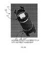
- FIG. 1is a top plan and perspective views of an embodiment of an ultracapacitor pack system.
- FIG. 2is an exploded perspective view of an embodiment of an ultracapacitor energy storage cell pack of the ultracapacitor pack system illustrated in FIG. 1 .
- FIG. 3is an exploded perspective view of an embodiment of an ultracapacitor pack assembly of the ultracapacitor energy storage cell pack of FIG. 2 .
- FIG. 4Ais a perspective view of an upper cradle member of the ultracapacitor pack assembly of FIG. 3 .
- FIG. 4Bis a perspective view of a lower cradle member of the ultracapacitor pack assembly of FIG. 3 .
- FIG. 5is a perspective view of an alternative embodiment of an ultracapacitor pack assembly.
- FIG. 6Ais a perspective view of the ultracapacitor pack assembly of FIG. 3 after a first step in a method of assembly of the ultracapacitor pack assembly.
- FIG. 6Bis a perspective view of the ultracapacitor pack assembly of FIG. 3 after a second step in a method of assembly of the ultracapacitor pack assembly.
- FIG. 6Cis a perspective view of the ultracapacitor pack assembly of FIG. 3 after a third step in a method of assembly of the ultracapacitor pack assembly.
- FIG. 6Dis a perspective view of the ultracapacitor pack assembly of FIG. 3 after a fourth step in a method of assembly of the ultracapacitor pack assembly.
- FIG. 7is a perspective view of an alternative embodiment of an ultracapacitor pack assembly.
- FIG. 8Ais a perspective view of a further embodiment of an ultracapacitor pack assembly.
- FIG. 8Bis a perspective view of an ultracapacitor and an embodiment of ultracapacitor holders for spacing and securing the ultracapacitors in the ultracapacitor pack assembly of FIG. 8A .
- FIG. 9Ais a top perspective view of a still further embodiment of an ultracapacitor pack assembly.
- FIG. 9Bis a bottom perspective view of the ultracapacitor pack assembly of FIG. 9A .
- FIG. 10is a perspective view of an embodiment of terminal heat sinks and an interconnect for a pair of ultracapacitors.
- FIG. 11Ais a side elevational view of another embodiment of a terminal heat sink being applied to an ultracapacitor.
- FIG. 11Bis a top plan view of the terminal heat sink of FIG. 11A .
- FIG. 11Cis a side elevational view of the terminal heat sink of FIG. 11A shown applied to the ultracapacitor.
- FIG. 12is a cross sectional view of an embodiment of an ultracapacitor pack cooling system of the ultracapacitor energy storage cell pack of FIG. 2 .
- FIG. 13is a perspective view of an alternative embodiment of an ultracapacitor energy storage.
- FIG. 14is schematic view of an ultracapacitor and shows how the ultracapacitor is supported in an embodiment of the cradle assembly of the ultracapacitor pack assembly.
- the ultracapacitor energy storage system 100includes a plurality of ultracapacitor energy storage cell packs 110 connected to a central water chiller 120 or cooling supply for cooling ultracapacitors of the ultracapacitor energy storage cell packs 110 , and a controller 130 for controlling cooling of the ultracapacitor energy storage cell packs 110 and/or controlling electrical functions (and/or other functions) of the ultracapacitor energy storage cell packs 110 .
- each ultracapacitor energy storage cell pack 110here includes 48 (6 ⁇ 8) ultracapacitors oriented so that the longitudinal axis of each ultracapacitor is vertically oriented.
- each ultracapacitor energy storage cell pack 110provides for low profile, modular ultracapacitor energy storage cell packs 110 that can be arranged in a variety of different configurations and numbers to provide the desired energy storage for the particular application.
- FIG. 1shows an exemplary configuration of six ultracapacitor energy storage cell packs 110 for assembly onto a rooftop of a metropolitan transit bus for supplying power to propel the bus.
- different configurations, arrangements/orientations, and/or numbers of ultracapacitor energy storage cell packs 110may be provided.
- the inventive principles described hereinare applied to batteries in a battery pack or other power supplies in a power supply pack.
- FIG. 2is an exploded perspective view of an embodiment of the ultracapacitor energy storage cell pack 110 of the ultracapacitor energy storage system 100 illustrated in FIG. 1 .
- FIG. 3is an exploded perspective view of an embodiment of an ultracapacitor pack assembly of the ultracapacitor energy storage cell pack of FIG. 2 , further exploding cradle assembly 160 .
- the exemplary ultracapacitor energy storage cell pack 110includes an ultracapacitor energy storage cell pack assembly 140 with 48 (6 ⁇ 8) ultracapacitors 150 secured in place relative to each other, housed within, and protected by cradle assembly 160 .
- the ultracapacitors 150are Maxwell—Boostcap® Ultracapacitors model BCAP3000, rated at 3000 Farads, 2.7 Volt operating voltage, >1 million duty cycles.
- terminal heat sinks 170which are disposed outside of cradle assembly 160 for cooling the ultracapacitors 150 in a manner to be described, are thermally connected to terminals 240 extending from opposite ends 250 , 260 of each ultracapacitor 150 .
- Interconnects 270form an electrical bridging device that electrically connects terminals 240 from adjacent ultracapacitors 150 (to connect the ultracapacitors 150 in series).
- the ultracapacitor energy storage cell pack 110includes a housing 180 comprised of an upper cover 190 and a lower cover 200 .
- the housing 180includes fastener mechanisms for fastening the upper cover 190 to the lower cover 200 .
- On an interior of the covers 190 , 200are structural supports for supporting the ultracapacitor energy storage cell pack assembly 140 at attachment/mounting points on the ultracapacitor energy storage cell pack assembly 140 .
- the attachment/mounting pointsmay be selected such that the pack assembly 140 is oriented in an advantageous orientation.
- Disposed within one end of the housing 180is a blower and cooler assembly 210 with a cross flow fan/flow source 220 and a heat exchanger 230 .
- circuitrymay be electrically coupled to the terminals 240 in a well-known manner.
- the cradle assembly 160 of the ultracapacitor pack assembly 140includes a vacuum-formed or pressure-formed plastic upper cradle member 280 and a matching vacuum-formed plastic lower cradle member 290 that form respective upper and lower array support structures for holding the ultracapacitors 150 by opposite end portions of the ultracapacitor cell bodies instead of by their terminals 240 .
- the cradle members 280 , 290may be made of a nonconductive material such as FR59 plastic.
- Each cradle member 280 , 290includes a peripheral flange 300 with spaced bolt holes 310 therein.
- the flange 300surrounds a central recessed/raised section 320 (i.e. recessed on an inner surface 350 /raised on an outer surface 360 ).
- Circular slots 330are disposed in a wall/partition 340 of each cradle member 280 , 290 to provide a terminal interface allowing the ultracapacitor terminals to pass through.
- Each slot 330includes a recessed annular wall 330 that projects outwardly from outer surface 360 .
- the annular wall 330has a diameter slightly smaller than an exterior diameter of the ultracapacitor 150 for securably receiving (i.e., to provide spring force and/or grip on) the end portions 250 , 260 of the ultracapacitor 150 .
- the cradle assembly 160may be further configured to direct air flow across the terminals.
- the cradle assembly 160may include vanes and/or form ducting such that air/coolant does not bleed out of the desired flow path, such that additional coolant is directed toward “hot spots” on the pack, such that back pressure on the flow source is reduced, etc.
- the cradle assembly 160enables the ultracapacitors 150 to be placed closer together than was possible in the past, making for a more compact ultracapacitor pack assembly 140 .
- the slots 330are disposed very close to one another.
- An additional advantage of disposing the slots 330 so close togetheris that the annular walls 330 are disposed close enough together so that the plastic material that forms structural support for one annular wall 330 adds to the structural support and rigidity of an adjacent annular wall 330 . This increases the structural support provided by the slots/cups 330 , increasing the structural support of the cradle assembly 160 (i.e., the plastic material forming the annular walls 330 doubles in on itself to form the additional structural support.
- the annular wall 330terminates at a proximal end in the wall/partition 340 and terminates at a distal end in annular flange 380 .
- Annular flange 380extends radially inwardly from the annular wall 330 and includes a central hole 390 with a diameter larger than an outer diameter of the terminal 240 (so the terminal 240 can pass there through) and smaller than the outer diameter of the ultracapacitor 150 so that the end portions 250 , 260 of the ultracapacitor 150 abut the annular flange 380 while the terminal 240 passes through the hole 390 .
- the circular slots 330form cups for securably receiving end portions 250 , 260 of the ultracapacitors 150 .
- the ultracapacitors 150are oriented along the dominant axis of vibration (See FIG. 14 ), which is typically vertically, as shown, for vehicle applications.
- the ultracapacitors 150are supported by their cylindrical body/case 434 and end portions/caps 250 , 260 rather than by their terminals 240 .
- a cradle assembly 400is shown.
- the cradle assembly 400is similar to the cradle assembly 160 described above except that the cradle assembly 400 includes leg stands 410 for supporting the cradle assembly 400 in the housing 180 .
- the cradle assembly 160 , 400includes additional or fewer features, such as, but not by way of limitation added stiffening ribs (e.g., integrally formed with the cradle members 280 , 290 ) or separate stiffeners (not shown) added between rows/columns of ultracapacitors 150 to add structure in the cradle members 280 , 290 or a smaller flange 300 (or no flange 300 ).
- the ultracapacitors 150are laterally supported or slid into a middle support structure between the cradle members 280 , 290 (or other top/bottom support plates/structures).
- the middle support structuremay be used for fire suppression, stress relief for the cradle assembly, vibration dampening, additional structure, and/or stability.
- the ultracapacitors 150are assembled into the slots/cups 330 of the lower cradle member 290 so that lower end portions 260 of the ultracapacitors 150 rest on the annular flange 380 while the terminals 240 pass through the holes 390 .
- the upper cradle member 280is assembled onto the ultracapacitors 150 so that top end portions 250 of the ultracapacitors 150 rest on the annular flange 380 while the terminals 240 pass through the holes 390 (i.e., top end portions 250 are assembled into the slots/cups 330 ).
- the interconnects 270are assembled so as to electrically connect terminals 240 from adjacent ultracapacitors 150 (to connect the ultracapacitors 150 in series).
- the terminal heat sinks 170are fastened to the terminals 240 .
- Fastenerse.g., bolts/nuts
- the cradle members 280 , 290generally enclose and protect the ultracapacitors 150 so that the ultracapacitor pack assembly 140 forms a module.
- the ultracapacitor pack assembly 140may be supported in the ultracapacitor energy storage cell pack 110 by the flanges 300 .
- the other components and/or circuitry of the ultracapacitor energy storage cell pack 110may be installed into the lower cover 200 before, during, or after the ultracapacitor pack assembly 140 is assembled and inserted into the ultracapacitor energy storage cell pack 110 .
- the ultracapacitor pack assembly 140is advantageous because it is quick, easy, and inexpensive to assemble/manufacture, includes fewer components that ultracapacitor pack assemblies in the past, relieves the terminals 240 from supporting the ultracapacitors 150 , is vibration resistant, forms a streamlined, compact ultracapacitor pack assembly, offers excellent high voltage isolation protection, provides robust environmental protection of components, particularly the ultracapacitors 150 , for heavy duty applications, and provides excellent thermal insulation to reduce system heat rejection requirements. Its modularity gives vehicle manufacturers and integrators flexibility in configuring the energy storage on the vehicle. In addition, it provides for a single, uniform module that can be used in varying numbers to meet diverse energy storage requirements.
- the ultracapacitors 150are disposed/supported with their longitudinal axis vertically oriented. End portions 250 , 260 and body 434 of the ultracapacitors 150 , as opposed to the terminals 240 , are structurally supported in the slots 330 of the cradle members 280 , 290 , protecting the structural integrity of the ultracapacitors 150 and preventing damage to the terminals 240 or damage to the ultracapacitors 150 from being structurally supported by the terminals 240 . Vibration during vehicle travel is often in a vertical (up and down) direction as shown.
- the cradle members 280 , 290combine to form a protective, sealed, enclosed housing/cover/box for the ultracapacitors 150 , protecting the ultracapacitors 150 from dirt, dust, debris, water, and other contamination.
- an alternative embodiment of an ultracapacitor pack assembly 420will be described. Similar to cradle assembly 160 , the ultracapacitors 150 are supported by the opposing end portions 250 , 260 of their casings, however, rather than wrapping down the sides of the array of ultracapacitors 150 and coupling to each other, the supporting members are kept apart and do not generally enclose the ultracapacitors 150 . Instead, the upper and lower supporting members are coupled to each other via an intermediate member. In this way access is provided to the center area of the ultracapacitors 150 between their terminals 240 . This may be beneficial for routing electronic circuitry (e.g., monitoring, balancing, and protection circuitry).
- electronic circuitrye.g., monitoring, balancing, and protection circuitry
- the ultracapacitor pack assembly 420includes an upper support board (e.g., FR4 board) 430 and a lower support board 440 with holes therein to receive end portions of ultracapacitors 150 .
- the ultracapacitors 150are oriented along the dominant axis of vibration (See FIG. 14 ), which is typically vertically, as shown, for vehicle applications.
- the ultracapacitors 150are supported by their cylindrical body/case 434 rather than by their terminals 240 .
- Plastic brackets 460are inexpensively disposed on outer surfaces of the support boards 430 , 440 for retaining the end portions of the ultracapacitors 150 in the Z-direction relative to the support boards 430 , 440 .
- Plastic blind rivets/plastic split shanks 470are used to fasten the plastic brackets 460 to the supports 430 , 440 via holes in the support boards 430 , 440 . It is understood that other means may be used to secure the ultracapacitor in the vertical direction.
- upper and lower support boardsmay integrate a cup interface to receive and restrain the end portions 250 , 260 of ultracapacitor 150 .
- a ring section of a second boardmay be attached to support boards 430 , 440 wherein its inner diameter is larger than the terminal but smaller than the end portion of the ultracapacitor cell, and the diameter of boards 430 , 440 are approximately the same as that of the cell.
- ultracapacitor pack assembly 471With reference to FIGS. 8A and 8B , a further embodiment of an ultracapacitor pack assembly 471 will be described. Here, a different approach is taken. Ultracapacitors 150 are equipped with adaptors or holders that transfer support loading to their end portions 250 , 260 . In addition, the adaptors/holders 475 extend the interface with the ultracapacitor to provide a flow path for a coolant to convect heat.
- the ultracapacitor pack assembly 471includes an upper support plate (e.g., ABS/PVC plate) 472 and a lower support plate 473 with sets of support holes or slots on inner surfaces of the plates 472 , 473 to receive spacer supports or support pegs 474 ( FIG.
- the ultracapacitors 150are preferably oriented along the dominant axis of vibration (See FIG. 14 ), which is typically vertically, as shown, for vehicle applications.
- Vertical support posts 476couple and support the support plates 472 , 473 and rest of the ultracapacitor pack assembly 471 .
- the ultracapacitor holders 475function as extension devices, one for each end of the ultracapacitor 150 . Moreover, the ultracapacitors 150 are supported by their cylindrical body/case 434 rather than by their terminals 240 . As illustrated, the ultracapacitor holders 475 include annular cuffs 477 that are akin to cup holders and slidably receive end portions of the ultracapacitors 150 . The support pegs 474 extend from the annular cuff 477 and are circumferentially spaced along the annular cuff 477 . When assembled as shown in FIG.
- the ultracapacitor holders 475perform the following functions: (1) space the ends of the ultracapacitors 150 from the inner surfaces of the support plates 472 , 473 ; (2) provide a passage for coolant (e.g., cooled air flow) to pass over the terminal heat sinks 170 for cooling the ultracapacitors 150 ; and (3) provide an interface with the support plates 472 , 473 .
- coolante.g., cooled air flow
- the ultracapacitor holders 475 and the support plates 472 , 473are interfaced so that the ultracapacitor holders 475 can not rotate, translate, or pass through the support plates 472 , 473 . In this way coolant flow can be better controlled in a predictably way.
- the support plates 472 , 473are fastened together, thus holding the ultracapacitors 150 by their cylindrical bodies/cases 434 only.
- the unified structurecan then be supported by a housing of the ultracapacitor pack assembly 471 .
- This embodimentlends itself well to low cost mass production wherein the uniform end holders are placed on both ends of the ultracapacitors 150 and inserted into machined slots in the support plates.
- the machined slotsare keyed such that the resultant flow path is made in an optimal predetermined manner.
- the ultracapacitor pack assembly 500includes a support matrix 510 (e.g., a foam or polymer core) with cylindrical holes therein having a diameter similar to the external diameter of the ultracapacitors 150 for slidably receiving/supporting the ultracapacitors 150 therein.
- a support matrix 510e.g., a foam or polymer core
- the support matrix 510may have plastic dividers or other support members disposed therein (e.g., elongated, thin plastic support dividers disposed between rows and/or columns of ultracapacitors 150 ) for adding structural support to the foam core support matrix 510 for example.
- the ultracapacitors 150are oriented along the dominant axis of vibration (See FIG. 14 ), which is typically vertically, as shown, for vehicle applications.
- the ultracapacitors 150are supported by their cylindrical body/case 434 rather than by their terminals 240 .
- the ultracapacitors 150may be held in position by friction force applied to the external surface/sides of the cylindrical body/case 434 .
- the ultracapacitors 150may be held by a pressure-fit within a supporting structure (e.g., a foam core support matrix 510 , a grid support structure having a friction interface (not shown), etc.).
- a supporting structuree.g., a foam core support matrix 510 , a grid support structure having a friction interface (not shown), etc.
- the cylindrical holes of the support matrix 510are slightly smaller than the external diameter of the ultracapacitors 150 ; the ultracapacitors 150 may be supported primarily laterally by their casings.
- the ultracapacitors 150may be positioned and held in place by injecting foam (or other setting material) between the ultracapacitors 150 and a supporting structure.
- foamor other setting material
- the multiple ultracapacitors 150are positioned in a structural grid, and then the filler material is applied. In this way, individual ultracapacitors 150 may be removed without disturbing the balance of the array.
- the structural gridmay be supported by a housing of the entire energy storage pack.
- the filler materialmay be a non-expanding friction material (e.g., rubber, epoxy, etc.) that is fixed to the grid and holds the canister in place.
- the ultracapacitors 150may be supported primarily by their end portions via end brackets fixed to the support matrix 510 .
- end brackets 530are fastened on the lower surface of the foam core support matrix 510 for retaining the end portions of the ultracapacitors 150 in the Z direction relative to the support matrix 510 .
- support matrix 510 , the filler material, and/or the gridare preferably made from a flame resistant material.
- vertical support posts 520may be used to support the support matrix 510 within the rest of the ultracapacitor pack assembly 500 .
- each interconnect 270forms a conductive path between the terminals 240 of two ultracapacitor cells 150 .
- interconnect 270may be made from a solid stamped piece of aluminum including a pair of flat terminal receivers 540 with holes 542 therein to receive the terminals 240 of the ultracapacitors 150 .
- interconnect 270may include an access point for cell control and monitoring.
- the flat terminal receivers 540include a bridge 550 , which may be flexible (e.g., thinner material used in bridge 550 and/or multiple preformed bends may be used to make this section flexible), having opposite upwardly angled sections 552 extending upwardly and inwardly from the flat terminal receivers 540 .
- the opposite upwardly angled sections 552are joined by a flat bridge section 554 .
- Each terminal heat sink 170forms a thermally conductive path away from the terminal 240 of ultracapacitor cell 150 that it is mechanically coupled to.
- terminal heat sink 170axially transfers heat more efficiently through the ultracapacitor terminals, instead of radially across the internal dielectric layers and through the canister walls.
- Further terminal heat sink 170may include a heat exchanger having a thermal performance sufficiently high that the terminal heat sink 170 provides at least half of the required cooling of the ultracapacitor cell 150 .
- terminal heat sink 170will be made of a material similar to that of the cell terminals. For example, since ultracapacitor terminals are often made of aluminum, terminal heat sink 170 could also be made of aluminum.
- terminal heat sink 170there are several benefits of using the terminal heat sink 170 as disclosed herein. For example, while some heat exchange takes place via interconnect 270 , the incorporation of cooling surfaces (e.g., fins) would tend to stiffen the interconnect and induce stress in the terminals.
- cooling surfacese.g., fins
- the omnidirectional orientation of terminal heat sink 170provides for a single component/device for use on each cell, independent of the cell's orientation in the series string and further provides for simple installation.
- the thermal performance required of terminal heat sink 170will vary according to each application. In particular, it may vary depending on parameters such as the performance desired of the cell, the convection mode and media, the flow rate of the convection media, the thermal gradient between the cell and coolant, etc. Once the parameters are known, the systemic heat transfer coefficient and terminal heat sink thermal performance may be determined as a result of a standard computational fluid dynamics (CFD) analysis.
- CFDcomputational fluid dynamics
- the terminal heat sink 170forms an energy storage cell terminal cooler/exchanger, or a device that radiates heat from an individual terminal 240 .
- the terminal heat sink 170couples to the terminal 240 and provides a heat exchange surface to the surrounding environment.
- the cooling fins 580form a convective heat exchange surface in an air flow path.
- the heat exchange surfacemay be integrated into a fastener for the terminal 240 (e.g., a threaded nut 570 ). Accordingly, the terminal heat sink 170 may both couple items to the ultracapacitor 150 terminal as needed and cool the terminal end of the ultracapacitor 150 at the same time.
- the terminal heat sink 170is configured to bolt a busbar (or other terminal-to-terminal interconnector/electrical bridging device) to the ultracapacitor 150 .
- the terminal heat sink 170may be configured to provide lateral support (i.e., along the longitudinal axis of the ultracapacitor 150 ) so as to support the ultracapacitor 150 within a housing or enclosure.
- the terminal heat sinks 170enable the ultracapacitors 150 to be packed more closely to each other so that cooling air is primarily passed across the terminal ends. By doing so, there is less need for a large cooling air/heat exchange path between the ultracapacitors 150 .
- each terminal heat sink 170includes a nut 570 with a threaded interior for threadably receiving externally threaded terminal 240 (see also, FIG. 11C ref. 620 ).
- the nut 570is welded to a cylindrical tube (not shown).
- the nut 570 and/or the tubeform a receiving section for structurally receiving externally threaded terminal 240 .
- Annular washers or cooling fins 580circumferentially surround and extend radially from the cylindrical tube.
- a top of the terminal heat sinks 170may include a rotate engagement mechanism/recessed tool interface 590 for rotatable engagement by/with a rotatable tool for screwing the terminal heat sink 170 on/off the externally threaded terminal 240 .
- the rotate engagement mechanism 590includes a “key” interface; particularly, three geometrically spaced cylindrical female sections (e.g. bores) for receiving three corresponding male members of a rotatable tool for screwing the terminal heat sink 170 on/off the externally threaded terminal 240 .
- a keyis required to remove the terminal heat sink 170 , providing added security against unauthorized disassembly.
- the rotate engagement mechanism 590may include other configurations/structures (e.g., screwdriver slot, Allen stock recess) for rotatable engagement by/with a rotatable tool.
- the rotate engagement mechanism 590is also important for controlling the amount of torque applied to the threaded terminal 240 so that the terminals 240 and ultracapacitors 150 are not damaged by applying too much torque.
- the rotate engagement mechanism 590is preferably recessed in the top/exposed end of the terminal heat sink 170 since it is preferable that whatever rotatable tool is used to screw/unscrew the terminal heat sink 170 comes in from the top/exposed portion of the threaded terminals 240 .
- the terminal heat sink 610is generally similar to the terminal heat sink 170 described above except that the terminal heat sink 610 includes an interiorly threaded nut 620 disposed above the cooling fins 580 instead of below the cooling fins 580 as with the heat sink 170 of FIG. 10 .
- Annular washers or cooling fins 580circumferentially surround and extend radially from cylindrical tube 630 . Cylindrical tube 630 may be smooth or internally threaded.
- the nut 620is a standard hexagonal nut.
- the standard hexagonal outer surface of the nut 620forms a rotate engagement mechanism for rotatable engagement by/with a rotatable tool (e.g., wrench) for screwing the terminal heat sink 610 on/off the externally threaded terminal 240 .
- a rotatable toole.g., wrench
- heatradiates in a longitudinal axial direction outwards, towards the terminals 240 , in the direction of the arrows shown.
- the heatis transferred to the terminals 240 , and from the terminals 240 , through the nut 620 /tube 630 and to the cooling fins 580 .
- Convective cooling airflows past the cooling fins 580 to transfer heat therefrom to cool the ultracapacitor 150 .
- the terminal heat sink 610may be simply, quickly, and easily manufactured by sliding L-type annular washer(s) 580 along the outside of the tube 630 into desired positions and enlarging the outer diameter of the tube 630 relative to an inner diameter of annular L-type washers (e.g., by forcing a ball bearing having a larger diameter than an inner diameter of the tube 630 through the tube 630 ) so that the washers are fixed to the tube 630 .
- the washer(s) 580may then be welded (or otherwise fixed) to the end of the tube 630 .
- terminal heat sink 610is manufactured by sliding L-type annular washers along the outside of the tube 630 into desired positions and fixing the inner annular portion of annular L-type washers to the outer circumference of the tube 630 and fixing the nut 620 to end of the tube 630 . Fixing the components together may be performed by brazing, welding, and/or other fixing techniques.
- terminal heat sink 170 , 610the number and/or configuration(s) of the heat fins 580 may vary/differ from that shown.
- terminal heat sink 170 , 610includes one or more of the following features, the terminal heat sink 170 , 610 radiates outwardly in a symmetric configuration from the receiving section, the symmetric configuration is annular, and/or the symmetric configuration is at least one of curvilinear (e.g., circular, annular, oval) and rectilinear (e.g., square, rectangular, rhomboid, parallelogram).
- curvilineare.g., circular, annular, oval
- rectilineare.g., square, rectangular, rhomboid, parallelogram
- the finsare preferably circular, in this way the terminal heat sink 170 , 610 provides omnidirectional cooling and may be installed in any direction, thus making installation quicker.
- the dimensions of the heat fins 580are preferably less than the diameter/dimensions of the ultracapacitors 150 .
- the outer diameter of the heat fins 580is less than the outer diameter of the ultracapacitor 150 . This minimizes the separation of adjacent cells and interaction between adjacent terminal heat sinks 170 , 610 .
- the first fin (closest to the ultracapacitor 150 endmay be in direct contact with the end of the cell for increased heat transfer, or alternately may stand off the end of the cell for increased coolant flow and convection.
- the terminal heat sink 170 , 610is advantageous because, but not by way of limitation, it extracts heat from the ultracapacitor cell in a thermally efficient manner and without the need for a high flow cooling system.
- the terminal heat sink 170 , 610provides a low-cost, simple solution for transferring heat from the ultracapacitors 150 .
- the terminal heat sink 170 , 610provides cooling for individual ultracapacitors 150 , and provides maximum cooling at the points (i.e., terminal ends) of highest heat.
- the terminal heat sink 170 , 610also allows for a more compact form factor in the ultracapacitor pack assembly because the ultracapacitors 150 can be placed closer together since cooling occurs at the terminals 240 and not at the cylindrical body/case 434 . Similarly, since the cells are cooled more efficiently, less cooling air is required and consequently much less energy is required to perform the same cooling.
- ultracapacitor pack cooling system 650for the ultracapacitor energy storage cell pack 140 will be described.
- ultracapacitor pack cooling system 650is a closed loop system. In this way, external contaminates commonly found in hybrid vehicles are excluded from the energy storage, thus extending its life and reliability.
- the ultracapacitor pack cooling system 650includes the blower and cooler assembly 210 disposed within one end of the housing 180 .
- the blower and cooler assembly 210includes the cross flow fan/flow source 220 and the heat exchanger 230 .
- the cross flow fan/flow source 220 and the heat exchanger 230are laterally elongated and extend substantially the entire lateral length of the ultracapacitor energy storage cell pack 140 .
- cross flow fan/flow source 220 and the heat exchanger 230is substantially the same width of each row (e.g., 6 rows shown in embodiment of FIG. 2 ).
- cross flow fan/flow source 220may be a fan extending the length of first row 692 of ultracapacitors 150 , or it may include the combination of a smaller fan and ducting or vanes distributing the flow to first row 692 of ultracapacitors 150 .
- a, front portion of the cross flow fan/flow source 220includes upper guide 660 and lower guide 670 that form a shroud for directing air flow from the cross flow fan/flow source 220 in the manner shown in FIG. 12 and minimizes leakage.
- Coolant flow or a coolant flow path 680flows over and through the upper terminal heat sinks 170 , causing convective cooling of the cooling fins 580 (transferring heat from the upper terminals 240 ) to cool the ultracapacitors 150 .
- Airflows around an opposite end of the ultracapacitor energy storage cell pack 140 and back to the heat exchanger 230 via a return flow or return flow path 690 .
- the return flow 690flows over and through the lower terminal heat sinks 170 , causing convective cooling of the cooling fins 580 (transferring heat from the lower terminals 240 ) to cool the ultracapacitors 150 .
- air flowwill be substantially or completely blocked from crossing/bleeding over the side of the ultracapacitor energy storage cell pack 140 . This may be accomplished with dedicated ducting/blockage/sealants and/or configuring structures such as the housing 180 or cradle assembly 160 to perform this task
- the temperature of the return flow 690is higher than the temperature of the coolant flow path 680 because the return flow 690 includes the heat removed from upstream flow across the terminal heat sinks 170 .
- the temperature gradient associated with the air flow above the first row 692 of ultracapacitors 150is the highest and the temperature gradient associated with the air flow below the first row 692 of ultracapacitors 150 is the lowest. Since, heat transfer occurs in a longitudinal axial direction outwards, towards the terminals 240 , in the direction of the arrows shown in FIG.
- the first row of cellsmay experience greater cooling at the top terminal than at the bottom terminal, whereas the last row of cells may experience a more even cooling at the top and bottom terminals.
- the average temperature of the air flow above and below each row of ultracapacitors 150is the same for every row (i.e., every row has the same average temperature). As a result, each row of ultracapacitors 150 (as well as all ultracapacitors 150 ) are cooled the same.
- the heat exchanger 230removes the added heat from the return flow 690 from the energy storage cell pack 110 .
- Heat exchanger 230may utilize an external cooling supply as well.
- heat exchanger 230will be integrated in a vehicle cooling system.
- a coolantwill pass through the energy storage cell pack 110 extracting heat from the hotter air flow. This may be accomplished by passing the coolant through a finned tube and passing the heated air flow across it.
- the heat exchanger 230 from each ultracapacitor energy storage cell pack 110may be connected to a central water chiller or cooling supply 120 for transferring coolant through the heat exchangers 230 for removing heat from the ultracapacitor energy storage cell packs 110 .
- the flowing coolanttakes heat from the ultracapacitors 150 , and the heat in the coolant is removed with the heat exchanger 230 .
- the controller 130may control cooling of the ultracapacitor energy storage cell packs 110 measuring the temperature of the packs and metering the coolant flow and/or temperature. Additionally, the heat exchanger 230 may be located external to the housing; however the cooling air of the pack is preferably part of a closed-loop system.
- both the cross flow fan/flow source 220 and the heat exchanger 230are integrated into the ultracapacitor energy storage cell pack 110 .
- the heat exchanger 230is cooled externally using coolant from either the vehicle cooling system (not shown) or a central water chiller or cooling supply 120 ( FIG. 1 ).
- one or both of the cross flow fan/flow source 220 the heat exchanger 230are not integrated into the ultracapacitor energy storage cell pack 110 .
- the ultracapacitors 150are vertically arranged in a single-level array, and the coolant (e.g., air) will pass over the top (and/or or bottom) of the ultracapacitors 150 , wrap around, and enter the heat exchanger 230 to extract heat.
- the terminal heat sinks 170 on the terminals 240form mini heat exchangers (e.g., finned nuts) so as to improve the transfer of heat from the terminals 240 to the coolant.
- This designis particularly good with ultracapacitors 150 because the internal construction of the ultracapacitors 150 makes it far more efficient to extract heat from the terminals 240 rather than the cases/cylindrical body 434 of the ultracapacitors 150 .
- the cooling airis propelled by cross flow fan 220 in a linear, uniform flow across the terminal heat sinks 170 .
- This cross flow fanalso called a tangential flow fan
- This cross flow fan 220efficiently redirects the air flow from the integrated heat exchanger 230 back over the terminal heat sinks 170 , thus closing the ultracapacitor cooling loop.
- the cross flow fan 220spans the long profiles associated with the cell array in the most efficient manner (compared to, for example, axial fans and centrifugal fans, which may require multiple motors and add bulk to the housing, based on their principles of operation).
- the above closed-loop cooling strategy/systemprovides active cooling, allowing operation of the ultracapacitor pack in all climates, and provides consistent cell-to-cell temperature control as compared to open loop systems that may vary depending on ambient conditions.
- the spacing between the ultracapacitorspreferably there should be no more that 0.25 in.-0.50 in. between the casings of the cells.
- the ultracapacitor pack system 100preferably includes ground fault circuit protection, a CAN vehicle interface, contactor protection hardware/software, microprocessor controlled cell equalization and monitoring, integral DC Bus precharge resistor(s), fast-acting fuse that reduces damage to DC bus components in event of a short circuit, diagnostic and prognostic functions to predict faults before they occur, and a monitoring system that monitors the voltage and temperature of every capacitor 150 to eliminate hidden cell failures.
- the ultracapacitor energy storage cell pack 700is generally similar to the ultracapacitor energy storage cell pack 110 of FIG. 2 , except instead of the ultracapacitor energy storage cell pack 110 including a single ultracapacitor energy storage cell pack assembly 140 , the ultracapacitor energy storage cell pack 700 includes more than one (e.g., 3) ultracapacitor energy storage cell pack assembly 140 disposed in respective inner thermoform liners 710 designed to readily receive all the components (e.g., ultracapacitor pack assemblies 140 ) of the ultracapacitor energy storage cell pack 700 for quick, inexpensive, and easy assembly.
- more than onee.g., 3
- ultracapacitor energy storage cell pack assembly 140disposed in respective inner thermoform liners 710 designed to readily receive all the components (e.g., ultracapacitor pack assemblies 140 ) of the ultracapacitor energy storage cell pack 700 for quick, inexpensive, and easy assembly.
- a single elongated cross-flow fan 720 and a single heat exchanger 730are used to cool the multiple ultracapacitor energy storage cell pack assemblies 140 .
- the single elongated cross-flow fan 720 , the single heat exchanger 730 , and the multiple ultracapacitor energy storage cell pack assemblies 140 /inner thermoform liners 710are disposed within a housing including a lower cover or sheet metal casing 750 and an upper cover or top 760 .
- the single heat exchangermay supply its own cooling or may be connected to a central water chiller or cooling supply 120 as described above for transferring coolant through heat exchanger(s) 730 for removing heat from one or more ultracapacitor energy storage cell packs 700 .
Landscapes
- Engineering & Computer Science (AREA)
- Power Engineering (AREA)
- Microelectronics & Electronic Packaging (AREA)
- Transportation (AREA)
- Mechanical Engineering (AREA)
- Life Sciences & Earth Sciences (AREA)
- Sustainable Development (AREA)
- Sustainable Energy (AREA)
- Physics & Mathematics (AREA)
- Thermal Sciences (AREA)
- Secondary Cells (AREA)
- Electric Double-Layer Capacitors Or The Like (AREA)
Abstract
Description
Claims (17)
Priority Applications (5)
| Application Number | Priority Date | Filing Date | Title |
|---|---|---|---|
| US12/343,957US7808771B2 (en) | 2008-12-23 | 2008-12-24 | High-power ultracapacitor energy storage pack and method of use |
| US12/489,748US7872856B2 (en) | 2008-12-23 | 2009-06-23 | Hybrid vehicle propulsion energy storage system |
| EP20090801342EP2368290A1 (en) | 2008-12-23 | 2009-12-15 | Hybrid vehicle propulsion energy storage system |
| PCT/US2009/068094WO2010075100A1 (en) | 2008-12-23 | 2009-12-15 | Hybrid vehicle propulsion energy storage system |
| US12/791,980US7916453B2 (en) | 2008-12-23 | 2010-06-02 | System and method for supporting a plurality of propulsion energy storage cells within a vehicle |
Applications Claiming Priority (2)
| Application Number | Priority Date | Filing Date | Title |
|---|---|---|---|
| US12/343,271US20100157527A1 (en) | 2008-12-23 | 2008-12-23 | High-Power Ultracapacitor Energy Storage Pack and Method of Use |
| US12/343,957US7808771B2 (en) | 2008-12-23 | 2008-12-24 | High-power ultracapacitor energy storage pack and method of use |
Related Parent Applications (1)
| Application Number | Title | Priority Date | Filing Date |
|---|---|---|---|
| US12/343,271ContinuationUS20100157527A1 (en) | 2008-12-23 | 2008-12-23 | High-Power Ultracapacitor Energy Storage Pack and Method of Use |
Related Child Applications (2)
| Application Number | Title | Priority Date | Filing Date |
|---|---|---|---|
| US12/489,748ContinuationUS7872856B2 (en) | 2008-12-23 | 2009-06-23 | Hybrid vehicle propulsion energy storage system |
| US12/791,980ContinuationUS7916453B2 (en) | 2008-12-23 | 2010-06-02 | System and method for supporting a plurality of propulsion energy storage cells within a vehicle |
Publications (2)
| Publication Number | Publication Date |
|---|---|
| US20100134974A1 US20100134974A1 (en) | 2010-06-03 |
| US7808771B2true US7808771B2 (en) | 2010-10-05 |
Family
ID=42222614
Family Applications (6)
| Application Number | Title | Priority Date | Filing Date |
|---|---|---|---|
| US12/343,271AbandonedUS20100157527A1 (en) | 2008-12-23 | 2008-12-23 | High-Power Ultracapacitor Energy Storage Pack and Method of Use |
| US12/343,970Expired - Fee RelatedUS7764496B2 (en) | 2008-12-23 | 2008-12-24 | Energy storage pack cooling system and method |
| US12/343,957Expired - Fee RelatedUS7808771B2 (en) | 2008-12-23 | 2008-12-24 | High-power ultracapacitor energy storage pack and method of use |
| US12/489,748Expired - Fee RelatedUS7872856B2 (en) | 2008-12-23 | 2009-06-23 | Hybrid vehicle propulsion energy storage system |
| US12/791,980Expired - Fee RelatedUS7916453B2 (en) | 2008-12-23 | 2010-06-02 | System and method for supporting a plurality of propulsion energy storage cells within a vehicle |
| US12/826,509Expired - Fee RelatedUS7859844B2 (en) | 2008-12-23 | 2010-06-29 | Energy storage cooling system |
Family Applications Before (2)
| Application Number | Title | Priority Date | Filing Date |
|---|---|---|---|
| US12/343,271AbandonedUS20100157527A1 (en) | 2008-12-23 | 2008-12-23 | High-Power Ultracapacitor Energy Storage Pack and Method of Use |
| US12/343,970Expired - Fee RelatedUS7764496B2 (en) | 2008-12-23 | 2008-12-24 | Energy storage pack cooling system and method |
Family Applications After (3)
| Application Number | Title | Priority Date | Filing Date |
|---|---|---|---|
| US12/489,748Expired - Fee RelatedUS7872856B2 (en) | 2008-12-23 | 2009-06-23 | Hybrid vehicle propulsion energy storage system |
| US12/791,980Expired - Fee RelatedUS7916453B2 (en) | 2008-12-23 | 2010-06-02 | System and method for supporting a plurality of propulsion energy storage cells within a vehicle |
| US12/826,509Expired - Fee RelatedUS7859844B2 (en) | 2008-12-23 | 2010-06-29 | Energy storage cooling system |
Country Status (3)
| Country | Link |
|---|---|
| US (6) | US20100157527A1 (en) |
| EP (1) | EP2368290A1 (en) |
| WO (1) | WO2010075100A1 (en) |
Cited By (20)
| Publication number | Priority date | Publication date | Assignee | Title |
|---|---|---|---|---|
| US20090002942A1 (en)* | 2005-07-25 | 2009-01-01 | Josef Seifert | Holding Device for Encased High-Protective Capacitors |
| WO2012128940A1 (en)* | 2011-03-21 | 2012-09-27 | Deere & Company | Capacitor assembly |
| WO2014134143A1 (en)* | 2013-02-27 | 2014-09-04 | loxus, Inc. | Energy storage device assembly |
| US9174525B2 (en) | 2013-02-25 | 2015-11-03 | Fairfield Manufacturing Company, Inc. | Hybrid electric vehicle |
| US9738976B2 (en) | 2013-02-27 | 2017-08-22 | Ioxus, Inc. | Energy storage device assembly |
| US9892868B2 (en) | 2013-06-21 | 2018-02-13 | Ioxus, Inc. | Energy storage device assembly |
| US9899643B2 (en) | 2013-02-27 | 2018-02-20 | Ioxus, Inc. | Energy storage device assembly |
| US9899150B2 (en) | 2014-05-12 | 2018-02-20 | Capacitor Sciences Incorporated | Energy storage device and method of production thereof |
| US9916931B2 (en) | 2014-11-04 | 2018-03-13 | Capacitor Science Incorporated | Energy storage devices and methods of production thereof |
| US9932358B2 (en) | 2015-05-21 | 2018-04-03 | Capacitor Science Incorporated | Energy storage molecular material, crystal dielectric layer and capacitor |
| US9941051B2 (en) | 2015-06-26 | 2018-04-10 | Capactor Sciences Incorporated | Coiled capacitor |
| US9978517B2 (en) | 2016-04-04 | 2018-05-22 | Capacitor Sciences Incorporated | Electro-polarizable compound and capacitor |
| US10026553B2 (en) | 2015-10-21 | 2018-07-17 | Capacitor Sciences Incorporated | Organic compound, crystal dielectric layer and capacitor |
| US10153087B2 (en) | 2016-04-04 | 2018-12-11 | Capacitor Sciences Incorporated | Electro-polarizable compound and capacitor |
| US10305295B2 (en) | 2016-02-12 | 2019-05-28 | Capacitor Sciences Incorporated | Energy storage cell, capacitive energy storage module, and capacitive energy storage system |
| US10340082B2 (en) | 2015-05-12 | 2019-07-02 | Capacitor Sciences Incorporated | Capacitor and method of production thereof |
| US10347423B2 (en) | 2014-05-12 | 2019-07-09 | Capacitor Sciences Incorporated | Solid multilayer structure as semiproduct for meta-capacitor |
| US10395841B2 (en) | 2016-12-02 | 2019-08-27 | Capacitor Sciences Incorporated | Multilayered electrode and film energy storage device |
| US10636575B2 (en) | 2016-02-12 | 2020-04-28 | Capacitor Sciences Incorporated | Furuta and para-Furuta polymer formulations and capacitors |
| US10872733B2 (en) | 2016-04-04 | 2020-12-22 | Capacitor Sciences Incorporated | YanLi material and dielectric and capacitor thereof |
Families Citing this family (77)
| Publication number | Priority date | Publication date | Assignee | Title |
|---|---|---|---|---|
| JP4788674B2 (en)* | 2007-07-05 | 2011-10-05 | トヨタ自動車株式会社 | Power supply |
| FR2924857B1 (en)* | 2007-12-06 | 2014-06-06 | Valeo Equip Electr Moteur | ELECTRICAL SUPPLY DEVICE COMPRISING A RECEPTION UNIT FOR ULTRA CAPACITY STORAGE UNITS |
| DE102007063195B4 (en)* | 2007-12-20 | 2013-08-29 | Daimler Ag | Battery with a housing and a heat conducting plate |
| WO2009110352A1 (en)* | 2008-03-05 | 2009-09-11 | カルソニックカンセイ株式会社 | Vehicle battery cooling device |
| US20100157527A1 (en)* | 2008-12-23 | 2010-06-24 | Ise Corporation | High-Power Ultracapacitor Energy Storage Pack and Method of Use |
| JP2010244978A (en)* | 2009-04-09 | 2010-10-28 | Toyota Motor Corp | Heat exchange medium and power storage device |
| WO2010148224A2 (en)* | 2009-06-18 | 2010-12-23 | Jason Fuhr | Battery module having a cell tray with thermal management features |
| KR101108184B1 (en) | 2009-12-11 | 2012-02-06 | 삼성에스디아이 주식회사 | Battery pack |
| US8149568B2 (en)* | 2010-03-18 | 2012-04-03 | Northern Lights Semiconductor Corp. | Load system for an Mcap energy storage module |
| JP5683688B2 (en)* | 2010-05-18 | 2015-03-11 | エンパイア テクノロジー ディベロップメント エルエルシー | Ultracapacitors using phase change materials |
| ES2372454B1 (en)* | 2010-07-07 | 2012-10-08 | Trainelec,S.L. | POWER STORAGE MODULE FOR RAILWAY VEHICLES. |
| EP2407983B1 (en)* | 2010-07-14 | 2017-02-01 | Vito NV | Method for packaging and connecting ultracapacitors for energy storage purposes |
| WO2012007290A1 (en)* | 2010-07-14 | 2012-01-19 | Vito Nv | Method for packaging and connecting ultracapacitors for energy storage purposes |
| JP5715135B2 (en)* | 2010-07-30 | 2015-05-07 | 三洋電機株式会社 | Secondary battery storage system rack |
| WO2012020624A1 (en)* | 2010-08-12 | 2012-02-16 | 日本ケミコン株式会社 | Capacitor device and method for manufacturing same |
| MX2013002538A (en)* | 2010-09-02 | 2013-05-17 | Proterra Inc | System and methods for battery management. |
| WO2012078727A2 (en) | 2010-12-07 | 2012-06-14 | Allison Transmission, Inc. | Energy storage system for hybrid electric vehicle |
| DE102011000353A1 (en)* | 2011-01-27 | 2012-08-02 | Dr. Ing. H.C. F. Porsche Aktiengesellschaft | battery |
| KR20120093620A (en)* | 2011-02-15 | 2012-08-23 | 삼성전기주식회사 | Capacitor module |
| DE102011101352A1 (en)* | 2011-05-12 | 2012-11-15 | Audi Ag | HV battery, in particular traction battery for a vehicle |
| TW201248972A (en)* | 2011-05-17 | 2012-12-01 | Ind Tech Res Inst | Car electric equipment case module |
| TWM421607U (en)* | 2011-08-30 | 2012-01-21 | Asia Vital Components Co Ltd | Heating and cooling module for battery |
| JP5953206B2 (en)* | 2011-11-11 | 2016-07-20 | 昭和電工株式会社 | Liquid cooling type cooling device and manufacturing method thereof |
| DE102012020516A1 (en)* | 2011-12-09 | 2013-06-13 | W.E.T. Automotive Systems Ag | Temperature control device for an electrochemical voltage source |
| EP2620965A1 (en)* | 2012-01-25 | 2013-07-31 | Volvo Car Corporation | Supercapacitors assembly with extended lifetime by heat and charging/discharging protection management of said supercapacitors |
| FR2986657B1 (en)* | 2012-02-03 | 2014-01-31 | Batscap Sa | POSITIONING SPACER, ENERGY STORAGE MODULE THE ASSEMBLY AND METHOD FOR ASSEMBLING THE MODULE |
| DE102012202539A1 (en)* | 2012-02-20 | 2013-08-22 | Siemens Aktiengesellschaft | Mounting assembly for electrical or electronic component e.g. capacitor in electrical device e.g. electromotor, has perforated plate that is set for pre-assembling and aligning electrical or electronic components to support frame |
| KR20130104615A (en)* | 2012-03-14 | 2013-09-25 | 삼성에스디아이 주식회사 | Battery charging system and method of thereof |
| US20130328387A1 (en)* | 2012-06-08 | 2013-12-12 | Sagar Venkateswaran | Supercapacitor vehicle and roadway system |
| JP2014011897A (en)* | 2012-06-29 | 2014-01-20 | Honda Motor Co Ltd | Electric power conversion system in electric vehicle |
| KR101877996B1 (en)* | 2012-09-07 | 2018-07-16 | 현대자동차주식회사 | Battery system |
| KR101371739B1 (en)* | 2012-09-07 | 2014-03-12 | 기아자동차(주) | Battery system |
| KR101371741B1 (en)* | 2012-09-07 | 2014-03-12 | 기아자동차(주) | Battery system |
| WO2014084415A1 (en)* | 2012-11-28 | 2014-06-05 | 에스케이이노베이션 주식회사 | Closed circulatory battery cooling system |
| DE102013208795A1 (en)* | 2013-05-14 | 2014-11-20 | Robert Bosch Gmbh | Cooling system with a cooling device for temperature control of a battery and method for controlling the temperature of a battery |
| FR3007887A1 (en)* | 2013-06-27 | 2015-01-02 | Batscap Sa | METHOD FOR MANUFACTURING AN ELECTRIC ENERGY STORAGE MODULE, ASSOCIATED MANUFACTURING DEVICE AND ELECTRIC ENERGY STORAGE MODULE OBTAINED BY CARRYING OUT THE METHOD |
| EP3032612B1 (en)* | 2013-08-09 | 2020-09-09 | Vehicle Energy Japan Inc. | Electricity storage module |
| KR20150111422A (en)* | 2014-03-21 | 2015-10-06 | 엘에스산전 주식회사 | Electronic component case for a vehicle |
| US9911532B2 (en)* | 2014-08-25 | 2018-03-06 | Raytheon Company | Forced convection liquid cooling of fluid-filled high density pulsed power capacitor with native fluid |
| US9620830B2 (en)* | 2014-12-16 | 2017-04-11 | Xinen Technology Hong Kong Company, Ltd. | Vehicle battery module with cooling and safety features |
| US9653824B2 (en) | 2015-04-10 | 2017-05-16 | Maxwell Technologies, Inc. | Reduced temperature energy storage device |
| DE102015208999A1 (en)* | 2015-05-15 | 2016-11-17 | Mahle International Gmbh | Energy storage of a motor vehicle |
| WO2017130168A1 (en)* | 2016-01-31 | 2017-08-03 | Ather Energy Pvt. Ltd. | A casing for an energy storage device |
| US9913411B2 (en) | 2016-04-27 | 2018-03-06 | General Electric Company | Thermal capacitance system |
| US10008752B1 (en) | 2016-12-23 | 2018-06-26 | Anhui Xinen Technology Co., Ltd. | Safety feature for energy storage device |
| US20180277808A1 (en)* | 2017-03-27 | 2018-09-27 | Martin Kruszelnicki | Battery Pack Module |
| EP3646360B1 (en)* | 2017-06-30 | 2025-03-12 | KYOCERA AVX Components Corporation | Interconnect strip for an ultracapacitor module |
| KR102534240B1 (en)* | 2017-06-30 | 2023-05-18 | 교세라 에이브이엑스 컴포넌츠 코포레이션 | Heat Dissipation from Balancing Circuit for Ultracapacitor Modules |
| FR3070549B1 (en)* | 2017-08-29 | 2020-12-04 | Delphi Int Operations Luxembourg Sarl | ELECTRICAL CONNECTION AND COOLING DEVICE FOR THIS CI |
| US11133133B2 (en)* | 2017-09-07 | 2021-09-28 | Avx Corporation | Supercapacitor module having matched supercapacitors |
| CN108169609B (en)* | 2017-12-25 | 2024-04-05 | 宁波中车新能源科技有限公司 | Super capacitor parallel charging and discharging tool |
| US11387054B2 (en) | 2018-02-22 | 2022-07-12 | KYOCERA AVX Components Corporation | Electrical circuit including a supercapacitor with reduced leakage |
| US11043337B2 (en) | 2018-02-22 | 2021-06-22 | Avx Corporation | Meter including a supercapacitor |
| EP3756203A4 (en)* | 2018-02-22 | 2021-11-17 | AVX Corporation | ENCAPSULATED SUPERCAPACITOR MODULE WITH HIGH VOLTAGE AND LOW EQUIVALENT SERIES RESISTANCE |
| KR102345048B1 (en)* | 2018-09-04 | 2021-12-28 | 주식회사 엘지에너지솔루션 | Secondary Battery Pack Having Radiant Heat Plate |
| CN109980321A (en)* | 2019-03-04 | 2019-07-05 | 北京长城华冠汽车科技股份有限公司 | Vehicle and cell apparatus and its thermal management algorithm |
| FR3094834B1 (en)* | 2019-04-05 | 2021-04-30 | Valeo Siemens eAutomotive France | CAPACITIVE BLOCK INCLUDING AN INSULATING ELECTRICAL MATERIAL FRAME |
| CN110265595B (en)* | 2019-06-03 | 2024-03-29 | 佛山科学技术学院 | Heat abstractor and group battery |
| US11267551B2 (en) | 2019-11-15 | 2022-03-08 | General Electric Company | System and method for cooling a leading edge of a high speed vehicle |
| US11427330B2 (en) | 2019-11-15 | 2022-08-30 | General Electric Company | System and method for cooling a leading edge of a high speed vehicle |
| US11260953B2 (en) | 2019-11-15 | 2022-03-01 | General Electric Company | System and method for cooling a leading edge of a high speed vehicle |
| US11260976B2 (en) | 2019-11-15 | 2022-03-01 | General Electric Company | System for reducing thermal stresses in a leading edge of a high speed vehicle |
| US11352120B2 (en) | 2019-11-15 | 2022-06-07 | General Electric Company | System and method for cooling a leading edge of a high speed vehicle |
| US11776757B1 (en)* | 2019-11-20 | 2023-10-03 | Smart Wires Inc. | Method for mounting high voltage capacitor banks |
| US11495974B2 (en) | 2020-02-25 | 2022-11-08 | Ucap Power, Inc. | Modular ultracapacitor energy storage/power delivery apparatus and methods |
| WO2022068337A1 (en)* | 2020-09-30 | 2022-04-07 | 东莞市趣电智能科技有限公司 | Heat dissipation module, and charging gun and charging base comprising same |
| US11742156B2 (en)* | 2020-10-26 | 2023-08-29 | KYOCERA AVX Components Corporation | Ultracapacitor module with improved vibration resistance |
| CN220774519U (en)* | 2020-12-04 | 2024-04-12 | 米沃奇电动工具公司 | Battery pack assembly |
| US11745847B2 (en) | 2020-12-08 | 2023-09-05 | General Electric Company | System and method for cooling a leading edge of a high speed vehicle |
| US11407488B2 (en) | 2020-12-14 | 2022-08-09 | General Electric Company | System and method for cooling a leading edge of a high speed vehicle |
| US11577817B2 (en) | 2021-02-11 | 2023-02-14 | General Electric Company | System and method for cooling a leading edge of a high speed vehicle |
| EP4315481A1 (en)* | 2021-03-25 | 2024-02-07 | Nerve Smart Systems A/S | A system and a method for thermal management of battery cells in a battery system |
| KR20240032011A (en)* | 2021-07-06 | 2024-03-08 | 교세라 에이브이엑스 컴포넌츠 코포레이션 | Data center rack with ultracapacitor modules |
| EP4148752A1 (en)* | 2021-09-10 | 2023-03-15 | ABB Schweiz AG | Capacitor assembly |
| IT202100031226A1 (en)* | 2021-12-13 | 2023-06-13 | Fast Charge Eng S R L | LIQUID COOLING SYSTEM DIRECT ON THE ELECTRICAL POWER CONNECTION ELEMENTS AND ON THE CELL POLES OF AN ELECTRIC ENERGY STORAGE SYSTEM FOR A VEHICLE WITH ELECTRIC PROPULSION AND PRESENTING ELECTRO-CHEMICAL BATTERIES, OR ELECTROSTATIC STORAGE SYSTEMS, CONNECTED TO EACH OTHER IN SERIES E AND PARALLEL |
| EP4194258A1 (en) | 2021-12-13 | 2023-06-14 | Fast Charge Engineering S.r.l. | Cooling circuit and vehicle with electrical propulsion having a cooling circuit |
| KR102795307B1 (en)* | 2022-09-19 | 2025-04-17 | (주)씨오알엔 | Modular battery pack with cooling system |
Citations (11)
| Publication number | Priority date | Publication date | Assignee | Title |
|---|---|---|---|---|
| US5449574A (en)* | 1994-12-06 | 1995-09-12 | Hughes Aircraft Company | Electical device having alternating layers of fibrous electrodes |
| US20050041370A1 (en) | 2001-10-04 | 2005-02-24 | Wilk Michael D. | High-power ultracapacitor energy storage pack and method of use |
| FR2863400A1 (en) | 2003-12-03 | 2005-06-10 | Electricite De France | Super-capacitor system for use in hybrid vehicles, has super-capacitors divided into two blocks, each with six super-capacitors connected in parallel and with fixation terminals fixed on radiators for cooling super-capacitors |
| US7016177B1 (en) | 2003-11-07 | 2006-03-21 | Maxwell Technologies, Inc. | Capacitor heat protection |
| US20070020513A1 (en) | 2001-10-04 | 2007-01-25 | Ise Corporation | Energy Storage Cell Support Separator and Cooling System for a Multiple Cell Module |
| WO2007031689A1 (en) | 2005-09-13 | 2007-03-22 | Valeo Equipements Electriques Moteur | Compact electric power supply device for a motor vehicle |
| US7203056B2 (en) | 2003-11-07 | 2007-04-10 | Maxwell Technologies, Inc. | Thermal interconnection for capacitor systems |
| WO2008099602A1 (en) | 2007-02-16 | 2008-08-21 | Panasonic Corporation | Electric storage unit |
| US7466536B1 (en)* | 2004-08-13 | 2008-12-16 | Eestor, Inc. | Utilization of poly(ethylene terephthalate) plastic and composition-modified barium titanate powders in a matrix that allows polarization and the use of integrated-circuit technologies for the production of lightweight ultrahigh electrical energy storage units (EESU) |
| US7477505B2 (en)* | 2005-10-18 | 2009-01-13 | General Hydrogen Corporation | Capacitor bank for electrical generator |
| US20090288695A1 (en)* | 2008-05-21 | 2009-11-26 | Deepak Jaisinghani | Hybrid Solar Power Generator |
Family Cites Families (46)
| Publication number | Priority date | Publication date | Assignee | Title |
|---|---|---|---|---|
| US4546415A (en)* | 1981-12-10 | 1985-10-08 | North American Philips Corporation | Heat dissipation aluminum electrolytic capacitor |
| US4930045A (en)* | 1989-10-26 | 1990-05-29 | Sundstrand Corporation | High power, high temperature disassemblable ceramic capacitor mount |
| US5142439A (en)* | 1991-08-28 | 1992-08-25 | Allied-Signal Inc. | Integrated bus bar/multilayer ceramic capacitor module |
| US5214564A (en)* | 1992-04-23 | 1993-05-25 | Sunstrand Corporation | Capacitor assembly with integral cooling apparatus |
| US5424143A (en)* | 1994-09-16 | 1995-06-13 | Electric Fuel (E.F.L.) Limited | Air-cooled, metal-air battery |
| DE19721287C1 (en)* | 1997-05-21 | 1998-07-23 | Siemens Matsushita Components | Electric component esp. aluminium electrolytic capacitor |
| DE19725843C1 (en)* | 1997-06-18 | 1998-10-29 | Siemens Matsushita Components | Aluminium-electrolyte capacitor for AC operation |
| JP4123541B2 (en)* | 1997-07-02 | 2008-07-23 | 株式会社デンソー | Battery cooling device |
| JPH11274001A (en)* | 1998-01-19 | 1999-10-08 | Hitachi Ltd | Power storage device and power conversion device using the same |
| US5872711A (en)* | 1998-01-20 | 1999-02-16 | Reliance Electric Industrial Company | Low impedance contoured laminated bus assembly and method for making same |
| US5914860A (en)* | 1998-01-20 | 1999-06-22 | Reliance Electric Industrial Company | Small volume heat sink/electronic assembly |
| JPH11329518A (en)* | 1998-05-21 | 1999-11-30 | Toshiba Battery Co Ltd | Battery device |
| US6631072B1 (en)* | 1998-12-05 | 2003-10-07 | Energy Storage Systems Pty Ltd | Charge storage device |
| DE19913450A1 (en)* | 1999-03-25 | 2000-09-28 | Mannesmann Sachs Ag | Power electronics for controlling electrical power machine performance/power section with capacitors connecting splint rings and screw joints while the lid connects to the housing with connections to the cooling device |
| DE10064648C2 (en)* | 1999-12-28 | 2003-09-18 | Honda Motor Co Ltd | battery unit |
| DE10009398C2 (en)* | 2000-02-28 | 2002-03-14 | Epcos Ag | Heatsink module and arrangement of heatsink modules |
| JP4921629B2 (en)* | 2000-03-31 | 2012-04-25 | パナソニック株式会社 | Fluid-cooled battery pack system |
| JP4046463B2 (en)* | 2000-08-03 | 2008-02-13 | 三洋電機株式会社 | Power supply |
| US6611421B2 (en)* | 2000-09-08 | 2003-08-26 | Avx Corporation | Non-polarized tantalum capacitor and capacitor array |
| JP4118014B2 (en)* | 2000-10-31 | 2008-07-16 | 三洋電機株式会社 | Power supply |
| WO2002039468A2 (en)* | 2000-11-09 | 2002-05-16 | Foc Frankenburg Oil Company Est. | A supercapacitor and a method of manufacturing such a supercapacitor |
| US6466429B1 (en)* | 2001-05-03 | 2002-10-15 | C And T Co., Inc. | Electric double layer capacitor |
| US6422027B1 (en)* | 2001-05-03 | 2002-07-23 | Ford Global Tech., Inc. | System and method for cooling a battery pack |
| US7085112B2 (en)* | 2001-10-04 | 2006-08-01 | Ise Corporation | High-power ultracapacitor energy storage pack and method of use |
| US6714391B2 (en)* | 2001-10-04 | 2004-03-30 | Ise Research Corporation | Ultracapacitor energy storage cell pack and methods of assembling and cooling the same |
| US6512347B1 (en)* | 2001-10-18 | 2003-01-28 | General Motors Corporation | Battery having an integral cooling system |
| US6620366B2 (en)* | 2001-12-21 | 2003-09-16 | Cool Options, Inc. | Method of making a capacitor post with improved thermal conductivity |
| JP4272387B2 (en)* | 2002-05-22 | 2009-06-03 | パナソニック株式会社 | Battery pack cooling device |
| JP4170714B2 (en)* | 2002-09-20 | 2008-10-22 | 松下電器産業株式会社 | Assembled battery |
| US7068507B2 (en)* | 2002-09-27 | 2006-06-27 | Rockwell Automation Technologies, Inc. | Compact liquid converter assembly |
| JP3845370B2 (en)* | 2002-11-29 | 2006-11-15 | 本田技研工業株式会社 | Storage element module |
| US6773301B1 (en)* | 2003-05-08 | 2004-08-10 | Jeffrey R. Chaskin | Cell strap for combining cells into a battery |
| US7027290B1 (en)* | 2003-11-07 | 2006-04-11 | Maxwell Technologies, Inc. | Capacitor heat reduction apparatus and method |
| US7180726B2 (en)* | 2003-11-07 | 2007-02-20 | Maxwell Technologies, Inc. | Self-supporting capacitor structure |
| JP4485187B2 (en)* | 2003-12-24 | 2010-06-16 | 本田技研工業株式会社 | Battery case |
| US7492574B2 (en)* | 2005-03-14 | 2009-02-17 | Maxwell Technologies, Inc. | Coupling of cell to housing |
| US7440258B2 (en)* | 2005-03-14 | 2008-10-21 | Maxwell Technologies, Inc. | Thermal interconnects for coupling energy storage devices |
| KR20060102853A (en)* | 2005-03-25 | 2006-09-28 | 삼성에스디아이 주식회사 | Secondary battery module |
| KR100903182B1 (en)* | 2005-09-28 | 2009-06-17 | 주식회사 엘지화학 | Cooling system of vehicle battery pack |
| KR100937903B1 (en)* | 2005-11-03 | 2010-01-21 | 주식회사 엘지화학 | Sealed heat exchange system of battery pack |
| US7554804B2 (en)* | 2006-06-30 | 2009-06-30 | Siemens Energy & Automation, Inc. | Electronic module configured for air flow therethrough and system including same |
| US7531270B2 (en)* | 2006-10-13 | 2009-05-12 | Enerdel, Inc. | Battery pack with integral cooling and bussing devices |
| WO2008095313A1 (en)* | 2007-02-09 | 2008-08-14 | Advanced Lithium Power Inc. | Battery thermal management system |
| JP4529991B2 (en)* | 2007-04-03 | 2010-08-25 | 株式会社デンソー | Battery cooling device |
| US20090080126A1 (en)* | 2007-09-25 | 2009-03-26 | Ise Corporation | Energy Storage Device Coupler and Method |
| US20100157527A1 (en)* | 2008-12-23 | 2010-06-24 | Ise Corporation | High-Power Ultracapacitor Energy Storage Pack and Method of Use |
- 2008
- 2008-12-23USUS12/343,271patent/US20100157527A1/ennot_activeAbandoned
- 2008-12-24USUS12/343,970patent/US7764496B2/ennot_activeExpired - Fee Related
- 2008-12-24USUS12/343,957patent/US7808771B2/ennot_activeExpired - Fee Related
- 2009
- 2009-06-23USUS12/489,748patent/US7872856B2/ennot_activeExpired - Fee Related
- 2009-12-15WOPCT/US2009/068094patent/WO2010075100A1/enactiveApplication Filing
- 2009-12-15EPEP20090801342patent/EP2368290A1/ennot_activeWithdrawn
- 2010
- 2010-06-02USUS12/791,980patent/US7916453B2/ennot_activeExpired - Fee Related
- 2010-06-29USUS12/826,509patent/US7859844B2/ennot_activeExpired - Fee Related
Patent Citations (12)
| Publication number | Priority date | Publication date | Assignee | Title |
|---|---|---|---|---|
| US5449574A (en)* | 1994-12-06 | 1995-09-12 | Hughes Aircraft Company | Electical device having alternating layers of fibrous electrodes |
| US20050041370A1 (en) | 2001-10-04 | 2005-02-24 | Wilk Michael D. | High-power ultracapacitor energy storage pack and method of use |
| US20070020513A1 (en) | 2001-10-04 | 2007-01-25 | Ise Corporation | Energy Storage Cell Support Separator and Cooling System for a Multiple Cell Module |
| US7016177B1 (en) | 2003-11-07 | 2006-03-21 | Maxwell Technologies, Inc. | Capacitor heat protection |
| US7203056B2 (en) | 2003-11-07 | 2007-04-10 | Maxwell Technologies, Inc. | Thermal interconnection for capacitor systems |
| FR2863400A1 (en) | 2003-12-03 | 2005-06-10 | Electricite De France | Super-capacitor system for use in hybrid vehicles, has super-capacitors divided into two blocks, each with six super-capacitors connected in parallel and with fixation terminals fixed on radiators for cooling super-capacitors |
| US7466536B1 (en)* | 2004-08-13 | 2008-12-16 | Eestor, Inc. | Utilization of poly(ethylene terephthalate) plastic and composition-modified barium titanate powders in a matrix that allows polarization and the use of integrated-circuit technologies for the production of lightweight ultrahigh electrical energy storage units (EESU) |
| WO2007031689A1 (en) | 2005-09-13 | 2007-03-22 | Valeo Equipements Electriques Moteur | Compact electric power supply device for a motor vehicle |
| US7477505B2 (en)* | 2005-10-18 | 2009-01-13 | General Hydrogen Corporation | Capacitor bank for electrical generator |
| WO2008099602A1 (en) | 2007-02-16 | 2008-08-21 | Panasonic Corporation | Electric storage unit |
| EP2104121A1 (en) | 2007-02-16 | 2009-09-23 | Panasonic Corporation | Electric storage unit |
| US20090288695A1 (en)* | 2008-05-21 | 2009-11-26 | Deepak Jaisinghani | Hybrid Solar Power Generator |
Non-Patent Citations (2)
| Title |
|---|
| International Search Report and Written Opinion dated Mar. 31, 2010 from PCT/US09/68094. |
| Internet Document "Image of BMW R69S Exhaust Finned Nut" available at http://w6rec.com/duane/bmw/exhaust/R69SNut.jpg (accessed Mar. 13, 2009). |
Cited By (31)
| Publication number | Priority date | Publication date | Assignee | Title |
|---|---|---|---|---|
| US20090002942A1 (en)* | 2005-07-25 | 2009-01-01 | Josef Seifert | Holding Device for Encased High-Protective Capacitors |
| US8068327B2 (en)* | 2005-07-25 | 2011-11-29 | Lenze Drives Gmbh | Holding device for encased high-protective capacitors |
| WO2012128940A1 (en)* | 2011-03-21 | 2012-09-27 | Deere & Company | Capacitor assembly |
| US8570767B2 (en) | 2011-03-21 | 2013-10-29 | Deere & Company | Capacitor assembly |
| CN103443887A (en)* | 2011-03-21 | 2013-12-11 | 迪尔公司 | Capacitor assembly |
| CN103443887B (en)* | 2011-03-21 | 2016-08-24 | 迪尔公司 | Capacitor assembly |
| US9174525B2 (en) | 2013-02-25 | 2015-11-03 | Fairfield Manufacturing Company, Inc. | Hybrid electric vehicle |
| US9878607B2 (en) | 2013-02-25 | 2018-01-30 | Fairfield Manufacturing Company, Inc. | Hybrid electric vehicle |
| WO2014134143A1 (en)* | 2013-02-27 | 2014-09-04 | loxus, Inc. | Energy storage device assembly |
| US9738976B2 (en) | 2013-02-27 | 2017-08-22 | Ioxus, Inc. | Energy storage device assembly |
| US9899643B2 (en) | 2013-02-27 | 2018-02-20 | Ioxus, Inc. | Energy storage device assembly |
| US9892868B2 (en) | 2013-06-21 | 2018-02-13 | Ioxus, Inc. | Energy storage device assembly |
| US10347424B2 (en) | 2014-05-12 | 2019-07-09 | Capacitor Sciences Incorporated | Energy storage device and method of production thereof |
| US10347423B2 (en) | 2014-05-12 | 2019-07-09 | Capacitor Sciences Incorporated | Solid multilayer structure as semiproduct for meta-capacitor |
| US10685782B2 (en) | 2014-05-12 | 2020-06-16 | Capacitor Sciences Incorporated | Capacitor and method of production thereof |
| US9899150B2 (en) | 2014-05-12 | 2018-02-20 | Capacitor Sciences Incorporated | Energy storage device and method of production thereof |
| US9916931B2 (en) | 2014-11-04 | 2018-03-13 | Capacitor Science Incorporated | Energy storage devices and methods of production thereof |
| US10340082B2 (en) | 2015-05-12 | 2019-07-02 | Capacitor Sciences Incorporated | Capacitor and method of production thereof |
| US9932358B2 (en) | 2015-05-21 | 2018-04-03 | Capacitor Science Incorporated | Energy storage molecular material, crystal dielectric layer and capacitor |
| US9941051B2 (en) | 2015-06-26 | 2018-04-10 | Capactor Sciences Incorporated | Coiled capacitor |
| US10854386B2 (en) | 2015-06-26 | 2020-12-01 | Capacitor Sciences Incorporated | Coiled capacitor |
| US10672561B2 (en) | 2015-06-26 | 2020-06-02 | Capacitor Sciences Incorporated | Coiled capacitor |
| US10026553B2 (en) | 2015-10-21 | 2018-07-17 | Capacitor Sciences Incorporated | Organic compound, crystal dielectric layer and capacitor |
| US10636575B2 (en) | 2016-02-12 | 2020-04-28 | Capacitor Sciences Incorporated | Furuta and para-Furuta polymer formulations and capacitors |
| US10305295B2 (en) | 2016-02-12 | 2019-05-28 | Capacitor Sciences Incorporated | Energy storage cell, capacitive energy storage module, and capacitive energy storage system |
| US10672560B2 (en) | 2016-04-04 | 2020-06-02 | Capacitor Sciences Incorporated | Electro-polarizable compound and capacitor |
| US10153087B2 (en) | 2016-04-04 | 2018-12-11 | Capacitor Sciences Incorporated | Electro-polarizable compound and capacitor |
| US10707019B2 (en) | 2016-04-04 | 2020-07-07 | Capacitor Science Incorporated | Electro-polarizable compound and capacitor |
| US9978517B2 (en) | 2016-04-04 | 2018-05-22 | Capacitor Sciences Incorporated | Electro-polarizable compound and capacitor |
| US10872733B2 (en) | 2016-04-04 | 2020-12-22 | Capacitor Sciences Incorporated | YanLi material and dielectric and capacitor thereof |
| US10395841B2 (en) | 2016-12-02 | 2019-08-27 | Capacitor Sciences Incorporated | Multilayered electrode and film energy storage device |
Also Published As
| Publication number | Publication date |
|---|---|
| US20100232105A1 (en) | 2010-09-16 |
| US20100134940A1 (en) | 2010-06-03 |
| US7872856B2 (en) | 2011-01-18 |
| US20100134974A1 (en) | 2010-06-03 |
| EP2368290A1 (en) | 2011-09-28 |
| WO2010075100A1 (en) | 2010-07-01 |
| US20100157532A1 (en) | 2010-06-24 |
| US7916453B2 (en) | 2011-03-29 |
| US7764496B2 (en) | 2010-07-27 |
| US20100157527A1 (en) | 2010-06-24 |
| US20100265660A1 (en) | 2010-10-21 |
| US7859844B2 (en) | 2010-12-28 |
Similar Documents
| Publication | Publication Date | Title |
|---|---|---|
| US7808771B2 (en) | High-power ultracapacitor energy storage pack and method of use | |
| EP2148789B1 (en) | Energy storage device | |
| EP2515361B1 (en) | Battery unit | |
| JP5543358B2 (en) | Vehicle power supply | |
| KR101431717B1 (en) | Bus Bar with Novel Structure | |
| JP5183175B2 (en) | Battery system | |
| US20140154539A1 (en) | Module for securing energy storage cells | |
| US10529965B2 (en) | Rack housing assembly and energy storage apparatus having the same | |
| WO2012133707A1 (en) | Power source device and vehicle provided with power source device | |
| US20120325447A1 (en) | Cooling system | |
| JP7593931B2 (en) | Battery module, and electric vehicle and power storage device equipped with the battery module | |
| CN205376309U (en) | Module including high electric power energy storage unit reaches energy memory including this module | |
| WO2011115796A2 (en) | Power cell array receiver | |
| JP7582769B2 (en) | Power supply device, electric vehicle equipped with the power supply device, and power storage device | |
| WO2023233417A1 (en) | Submerged liquid-cooled modular battery system | |
| US20130022853A1 (en) | Modular Variable Compression Thermal Management Battery Retaining System | |
| US20080318120A1 (en) | Power storage unit | |
| KR100590017B1 (en) | Secondary battery module | |
| EP4579908A1 (en) | Battery pack and energy storage system comprising same | |
| Bolsinger et al. | Integral Battery Architecture with Cylindrical Cells as Structural Elements | |
| WO2024141992A1 (en) | Silicone arrangement for supporting battery cells | |
| HK1181553A (en) | Battery pack for electric vehicles |
Legal Events
| Date | Code | Title | Description |
|---|---|---|---|
| AS | Assignment | Owner name:ISE CORPORATION,CALIFORNIA Free format text:ASSIGNMENT OF ASSIGNORS INTEREST;ASSIGNORS:NGUYEN, VINH-DUY;SMITH, ALEXANDER J.;STONE, KEVIN T.;AND OTHERS;SIGNING DATES FROM 20090316 TO 20090528;REEL/FRAME:022761/0174 Owner name:ISE CORPORATION, CALIFORNIA Free format text:ASSIGNMENT OF ASSIGNORS INTEREST;ASSIGNORS:NGUYEN, VINH-DUY;SMITH, ALEXANDER J.;STONE, KEVIN T.;AND OTHERS;SIGNING DATES FROM 20090316 TO 20090528;REEL/FRAME:022761/0174 | |
| AS | Assignment | Owner name:BLUWAYS USA, INC., CALIFORNIA Free format text:ASSIGNMENT OF ASSIGNORS INTEREST;ASSIGNOR:ISE CORPORATION;REEL/FRAME:026221/0077 Effective date:20110201 | |
| AS | Assignment | Owner name:BLUWAYS, N.V., BELGIUM Free format text:ASSIGNMENT OF ASSIGNORS INTEREST;ASSIGNOR:BLUWAYS USA, INC.;REEL/FRAME:026899/0061 Effective date:20110808 | |
| AS | Assignment | Owner name:BLUWAYS USA, INC., CALIFORNIA Free format text:ASSIGNMENT OF ASSIGNORS INTEREST;ASSIGNOR:BLUWAYS, N.V.;REEL/FRAME:026952/0172 Effective date:20110920 | |
| AS | Assignment | Owner name:SHEPPARD, MULLIN, RICHTER & HAMPTON, LLP, CALIFORN Free format text:COURT-ISSUED WRIT OF ATTACHMENT;ASSIGNOR:BLUWAYS USA, INC.;REEL/FRAME:028466/0829 Effective date:20120316 | |
| AS | Assignment | Owner name:SHEPPARD, MULLIN, RICHTER & HAMPTON, LLP, CALIFORN Free format text:COURT-ISSUED JUDGMENT AGAINST SAID PATENTS;ASSIGNOR:BLUWAYS USA, INC.;REEL/FRAME:028703/0690 Effective date:20120720 | |
| AS | Assignment | Owner name:SHEPPARD, MULLIN, RICHTER & HAMPTON LLP, CALIFORNI Free format text:ORDER TO APPEAR FOR EXAMINATON;ASSIGNOR:BLUWAYS USA, INC.;REEL/FRAME:029445/0708 Effective date:20121203 | |
| AS | Assignment | Owner name:DE CAMARA, POST-JUDGMENT RECEIVER FOR BLUWAYS USA, Free format text:ASSIGNMENT OF ASSIGNORS INTEREST;ASSIGNOR:BLUWAYS USA, INC.;REEL/FRAME:030271/0130 Effective date:20130417 | |
| AS | Assignment | Owner name:DE CAMARA, POST-JUDGMENT RECEIVER FOR BLUWAYS USA, Free format text:ASSIGNMENT OF ASSIGNORS INTEREST;ASSIGNOR:BLUWAYS USA, INC.;REEL/FRAME:030450/0598 Effective date:20130503 | |
| AS | Assignment | Owner name:SHEPPARD, MULLIN, RICHTER & HAMPTON LLP, CALIFORNI Free format text:ORDER EXTENDING LIEN PURSUANT TO CAL. CODE CIV. P. SEC. 708.110(D);ASSIGNOR:BLUWAYS USA, INC.;REEL/FRAME:031721/0608 Effective date:20131125 | |
| REMI | Maintenance fee reminder mailed | ||
| AS | Assignment | Owner name:SHEPPARD, MULLIN, RICHTER & HAMPTON LLP, CALIFORNI Free format text:ASSIGNMENT OF ASSIGNORS INTEREST;ASSIGNOR:DE CAMARA, POST-JUDGMENT RECEIVER FOR BLUWAYS USA, INC., ANDREW;REEL/FRAME:033664/0702 Effective date:20140815 | |
| LAPS | Lapse for failure to pay maintenance fees | ||
| STCH | Information on status: patent discontinuation | Free format text:PATENT EXPIRED DUE TO NONPAYMENT OF MAINTENANCE FEES UNDER 37 CFR 1.362 | |
| FP | Lapsed due to failure to pay maintenance fee | Effective date:20141005 |