US7806909B2 - Line lock threading systems and methods - Google Patents
Line lock threading systems and methodsDownload PDFInfo
- Publication number
- US7806909B2 US7806909B2US10/942,275US94227504AUS7806909B2US 7806909 B2US7806909 B2US 7806909B2US 94227504 AUS94227504 AUS 94227504AUS 7806909 B2US7806909 B2US 7806909B2
- Authority
- US
- United States
- Prior art keywords
- passageways
- suture
- line lock
- along
- line
- Prior art date
- Legal status (The legal status is an assumption and is not a legal conclusion. Google has not performed a legal analysis and makes no representation as to the accuracy of the status listed.)
- Active, expires
Links
Images


Classifications
- A—HUMAN NECESSITIES
- A61—MEDICAL OR VETERINARY SCIENCE; HYGIENE
- A61B—DIAGNOSIS; SURGERY; IDENTIFICATION
- A61B17/00—Surgical instruments, devices or methods
- A61B17/04—Surgical instruments, devices or methods for suturing wounds; Holders or packages for needles or suture materials
- A61B17/0487—Suture clamps, clips or locks, e.g. for replacing suture knots; Instruments for applying or removing suture clamps, clips or locks
- A—HUMAN NECESSITIES
- A61—MEDICAL OR VETERINARY SCIENCE; HYGIENE
- A61B—DIAGNOSIS; SURGERY; IDENTIFICATION
- A61B17/00—Surgical instruments, devices or methods
- A61B17/04—Surgical instruments, devices or methods for suturing wounds; Holders or packages for needles or suture materials
- A61B17/0401—Suture anchors, buttons or pledgets, i.e. means for attaching sutures to bone, cartilage or soft tissue; Instruments for applying or removing suture anchors
- A61B2017/0404—Buttons
- A—HUMAN NECESSITIES
- A61—MEDICAL OR VETERINARY SCIENCE; HYGIENE
- A61B—DIAGNOSIS; SURGERY; IDENTIFICATION
- A61B17/00—Surgical instruments, devices or methods
- A61B17/04—Surgical instruments, devices or methods for suturing wounds; Holders or packages for needles or suture materials
- A61B17/0401—Suture anchors, buttons or pledgets, i.e. means for attaching sutures to bone, cartilage or soft tissue; Instruments for applying or removing suture anchors
- A61B2017/0446—Means for attaching and blocking the suture in the suture anchor
- A61B2017/0458—Longitudinal through hole, e.g. suture blocked by a distal suture knot
- A—HUMAN NECESSITIES
- A61—MEDICAL OR VETERINARY SCIENCE; HYGIENE
- A61B—DIAGNOSIS; SURGERY; IDENTIFICATION
- A61B17/00—Surgical instruments, devices or methods
- A61B17/04—Surgical instruments, devices or methods for suturing wounds; Holders or packages for needles or suture materials
- A61B17/0401—Suture anchors, buttons or pledgets, i.e. means for attaching sutures to bone, cartilage or soft tissue; Instruments for applying or removing suture anchors
- A61B2017/0446—Means for attaching and blocking the suture in the suture anchor
- A61B2017/0459—Multiple holes in the anchor through which the suture extends and locking the suture when tension is applied
- A—HUMAN NECESSITIES
- A61—MEDICAL OR VETERINARY SCIENCE; HYGIENE
- A61B—DIAGNOSIS; SURGERY; IDENTIFICATION
- A61B17/00—Surgical instruments, devices or methods
- A61B17/04—Surgical instruments, devices or methods for suturing wounds; Holders or packages for needles or suture materials
- A61B17/0487—Suture clamps, clips or locks, e.g. for replacing suture knots; Instruments for applying or removing suture clamps, clips or locks
- A61B2017/0488—Instruments for applying suture clamps, clips or locks
- A—HUMAN NECESSITIES
- A61—MEDICAL OR VETERINARY SCIENCE; HYGIENE
- A61B—DIAGNOSIS; SURGERY; IDENTIFICATION
- A61B17/00—Surgical instruments, devices or methods
- A61B17/04—Surgical instruments, devices or methods for suturing wounds; Holders or packages for needles or suture materials
- A61B2017/0496—Surgical instruments, devices or methods for suturing wounds; Holders or packages for needles or suture materials for tensioning sutures
- Y—GENERAL TAGGING OF NEW TECHNOLOGICAL DEVELOPMENTS; GENERAL TAGGING OF CROSS-SECTIONAL TECHNOLOGIES SPANNING OVER SEVERAL SECTIONS OF THE IPC; TECHNICAL SUBJECTS COVERED BY FORMER USPC CROSS-REFERENCE ART COLLECTIONS [XRACs] AND DIGESTS
- Y10—TECHNICAL SUBJECTS COVERED BY FORMER USPC
- Y10T—TECHNICAL SUBJECTS COVERED BY FORMER US CLASSIFICATION
- Y10T24/00—Buckles, buttons, clasps, etc.
- Y10T24/39—Cord and rope holders
- Y10T24/3916—One-piece
- Y10T24/3927—Slack adjuster
Definitions
- the present inventionrelates generally to devices to replace knots and more specifically to devices to replace surgical knots tied in open, arthroscopic, and endoscopic procedures.
- Line locksgenerally operate in one of two ways. Some line locks are manually actuated to secure one or more lines so that tension is maintained in a portion of the line(s). Once actuated, the line lock resists sliding along the line(s) either toward or away from the tensioned portion of the line. Other line locks are continuously adjustable in one direction so that tension is increased in the portion of the line upon which the line lock is advanced. The continuously adjustable line locks resist movement away from the tensioned portion of the line, but can be further advanced toward the tensioned portion of the line with an appropriately applied force.
- the portion of a line that is put under tension, typically to secure some object,is commonly referred to as the standing end.
- the portion of the line that extends toward the line handleris commonly referred to as the working end.
- a knot in a line, or a line lock attached to a line,is the demarcation between the standing end and the working end.
- Continuously adjustable line locksoffer several advantages. They are passive locking devices, meaning that no other operation is required to secure the line lock once it is moved along the line to its desired position. Furthermore, these line locks can be used to continuously increase the tension in the standing end until it reaches a desired level of tension.
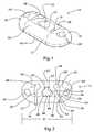
- FIG. 1is a perspective view of an adjustable line lock.
- FIG. 2is a top plan view of line lock shown in FIG. 1 .
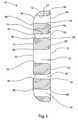
- FIG. 3is an elevated cross sectional side view of the line lock shown in FIG. 1 .
- FIG. 4Ais a perspective view of the line lock shown in FIG. 1 with a line routed therethrough in a slack unlocked position.
- FIG. 4Bis a perspective view of the line lock shown in FIG. 4A with the line in a tensioned locked position.
- FIG. 5is a top plan view of the line lock shown in FIG. 4B .
- FIG. 6is a bottom plan view of the line lock shown in FIG. 4B .
- FIG. 7is a perspective view of the line lock shown in FIG. 4A with the line routed in a different path.
- FIG. 8is a perspective view of an alternative embodiment of the line lock shown in FIG. 1 with open working passageways.
- FIG. 9is a perspective view of another alternative embodiment of the line lock shown in FIG. 1 with open passageways.
- FIG. 10is a perspective view of another alternative embodiment of the line lock shown in FIG. 1 with dual primary passageways and uniform working passageways.
- FIG. 11is a perspective view of a line lock for use with a single strand of line.
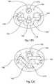
- FIG. 12Ais a perspective view of the line lock shown in FIG. 11 with a line routed therethrough.
- FIG. 12Bis a top plan view of the line lock shown in FIG. 12A .
- FIG. 12Cis a bottom plan view of the line lock shown in FIG. 12A .
- FIG. 13Ais a top perspective view of a line lock having dual strands of line routed therethrough.
- FIG. 13Bis a bottom perspective view of the line lock shown in FIG. 13A .
- FIG. 14Ais a top perspective view of a line lock having a line secured thereto.
- FIG. 14Bis a bottom perspective view of the line lock shown in FIG. 14A .
- FIG. 15is a perspective view of an alternative embodiment of a line lock.
- FIG. 16Ais a perspective view of the line lock shown in FIG. 15 with a line routed therethrough.
- FIG. 16Bis a top plan view of the line lock shown in FIG. 16A .
- FIG. 16Cis a bottom plan view of the line lock shown in FIG. 16A .
- FIG. 17is a perspective view of another alternative embodiment of a line lock.
- FIG. 18Ais a perspective view of the line lock shown in FIG. 17 with a line routed therethrough.
- FIG. 18Bis a top plan view of the line lock shown in FIG. 18A .
- FIG. 18Cis a bottom plan view of the line lock shown in FIG. 18A .
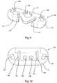
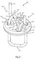
- FIG. 19is a perspective view of a line lock according to another alternative embodiment of the invention, with an associated insertion tool.
- FIG. 20is a perspective view of the line lock of FIG. 19 , with a suture passing loosely through the passageways of the line lock.
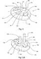
- FIG. 21is a perspective view of the line lock of FIG. 19 , with suture passing tightly through the passageways of the line lock.
- FIG. 22is a perspective view of a system including a cartridge with threaders that facilitate the insertion of suture through the passageways of the line lock of FIG. 19 .
- FIG. 23is a perspective view of the system of FIG. 22 , with the lid of the cartridge open and sutures coupled to the trailing ends of the threaders.
- FIG. 24is a perspective view of the system of FIG. 22 , with the cartridge open and one of the sutures drawn part-way through the cartridge.
- FIG. 25is a perspective view of the system of FIG. 22 , with the cartridge open and the sutures fully drawn through the cartridge to pass through the passageways of the line
- FIG. 26is a perspective view of the system of FIG. 22 , with the cartridge open and the sutures and line lock removed from the cartridge for use.
- the present inventionrelates to line locks that can be used in part to replace surgical knots tied in sutures in open, arthroscopic, and endoscopic procedures.
- the line lockscan be used outside of surgical procedures for any use where it is desired to selectively adjust and/or tie off a line such as a rope, cord, string, or other conventional type of line.
- Line lock 10comprises an elongated body 12 having a top surface 14 and an opposing bottom surface 16 that each extend between a first end 18 and an opposing second end 20 .
- Body 12also has a first side 19 and an opposing second side 21 extending between first end 18 and second end 20 .
- body 12has a substantially rectangular configuration with rounded ends.
- body 12can be any desired configuration such as triangular, circular, square or any other polygonal or irregular configuration.
- body 12has a maximum dimension D along its length ( FIG. 2 ) which is typically less than about 2 cm, more commonly less than about 1.5 cm, and even more commonly less than about 1 cm. Other dimensions can also be used.
- body 12has a height in a range between about 1 mm to about 1.5 mm, a width in a range between about 2 mm to about 3 mm, and length D in a range between about 5 mm to about 8 mm.
- body 12can be any desired dimension.
- maximum dimension Dcan be in a range from about 5 cm to about 0.5 m. Again, other dimensions can also be used.
- body 12can be comprised of any biocompatible material.
- the biocompatible materialcan be bioabsorbable or non-bioabsorbable. Examples of typical materials include non-bioabsorbable plastic, bioabsorbable plastic, synthetic tissue, and allograft tissue.
- body 12can be made of any desired material such as metal, plastic, wood, fiberglass, composite, or the like.
- a primary passageway 22centrally extending through body 10 between top surface 14 and bottom surface 16 is a primary passageway 22 .
- the term “passageway”is broadly intended to include closed apertures, such as depicted by primary passageway 22 , partially bound apertures, open channels, recesses, grooves, slots, and the like, that are capable of receiving a line and at least partially retaining the line therein.
- the term “line” as used in the specification and appended claimsis broadly intended to include suture, cord, rope, filament, wire, cable, and any other form of line.
- first secondary passageway 24Extending between surfaces 14 and 16 at first end 18 of body 12 is a first secondary passageway 24 .
- a second secondary passageway 24 ′extends between surfaces 14 and 16 at second end 20 .
- Extending through body 12 at a location between primary passageway 22 and first secondary passageway 24is a first working passageway 28 .
- first working passageway 28is disposed between primary passageway 22 and first secondary passageway 24 such that a geometric line segment 36 ( FIG. 2 ) can be extended between primary passageway 22 and first secondary passageway 24 so that line segment 36 intersects with first working passageway 28 .
- a second working passageway 28 ′extends through body 12 at a location between primary passageway 22 and second secondary passageway 24 ′.
- Each working passageway 28 and 28 ′has an elongated transverse cross sectional area that extends between a first end 38 and an opposing second end 40 .
- Each working passageway 28 , 28 ′comprises an enlarged access region 32 at first end 38 which communicates with a constricted capture slot 34 at second end 40 .
- Access region 32is sized to enable easy feeding of a line into and through the corresponding working passageways 28 , 28 ′. Accordingly, although access region 32 can be slightly smaller than the transverse cross sectional area of the line which is to be passed therethrough, access region 32 typically has a transverse cross sectional area that is equal to or slightly larger than the transverse cross sectional area of the line that is to be passed therethrough.
- capture slot 34has a width W that is substantially equal to or less than the diameter of the line that is to be passed through working passageways 28 , 28 ′.
- width Wis less than about 0.9 times the diameter of the line and more commonly less than about 0.75 times the diameter of the line.
- working passageways 28 , 28 ′can come in a variety of different configurations.
- capture slot 34can come in a variety of different constricted, tapered, or notched shaped configurations that are capable of securely retaining a line through wedged engagement.
- the required difference between the width W and the diameter of the linemay be less than the examples given above.
- central passageway 22is bounded by an interior surface 42 of body 12 having a substantially triangular transverse cross section.
- Interior surface 42comprises a first side face 44 disposed toward first working passageway 28 , a second side face 46 disposed toward second working passageway 28 ′ and which intersects with first side face 44 , and a third side face 48 extending between first side face 44 and second side face 46 .
- side faces 44 and 46are shown as being substantially flat, in alternative embodiments side faces 44 and 46 can be curved or irregular. In one embodiment, however, first side face 44 is substantially disposed in or tangent to a first plane illustrated by dashed line 50 . With reference to FIG. 2 , plane 50 slopes toward second end 40 of first working passageway 28 as plane 50 extends from first side 19 of body 12 to second side 21 .
- First secondary passageway 24is bounded by an interior surface 54 of body 12 having an elongated transverse cross section. Interior surface 54 comprises a first side face 56 disposed toward first working passageway 28 and an opposing second side face 58 . Although side faces 56 and 58 are shown as being substantially flat, in alternative embodiments side faces 56 and 58 can also be curved or irregular. Again, in one embodiment first side face 56 is substantially disposed in or tangent to a second plane illustrated by dashed line 60 . With reference to FIG. 2 , second plane 60 slopes toward second end 40 of first working passageway 28 as second plane 60 extends from first side 19 of body 12 to second side 21 .
- first plane 50 and second plane 60are disposed so as to be converging as they extend from first side 19 of body 12 to second side 21 .
- planes 50 and 60intersect at a location 62 on body 12 that is at least substantially aligned with a central longitudinal axis of capture slot 34 .
- location 62can be directly adjacent to body 12 or at a distance from body 12 .
- location 62need not be aligned with the central longitudinal axis of capture slot 34 .
- planes 50 and 60are disposed at equally opposing angles relative to the central longitudinal axis of capture slot 34 .
- planes 50 and 60can intersect so as to form an inside angle therebetween in a range between about 5° to about 85°.
- Second secondary passageway 24 ′has substantially the same configuration as first secondary passageway 24 .
- second secondary passageway 24 ′has substantially the same relative position to second working passageway 28 ′ and second side face 46 of primary passageway 22 as first secondary passageway 26 has to first working passageway 28 and first side face 44 of primary passageway 22 .
- planes 50 and 60are also applicable to primary passageway 22 and second secondary passageway 24 ′.
- primary passageway 22has a length in a range between about 1.3 mm to about 1.5 mm and a width in a range between about 1 mm to about 1.3 mm.
- Secondary passageways 24 and 24 ′have a width of about 0.8 mm and a length in a range between 1 mm to about 1.3 mm.
- Access region 32 of working passageways 28 and 28 ′have width in a range between about 0.7 mm to 1 mm while capture slots 17 have a width in a range between about 0.3 mm to 0.4 mm.
- interior surface 42 of primary passageway 22extends to a top outside corner 66 and an opposing bottom outside corner 68 .
- Top outside corner 66bounds a top primary opening 70 while bottom outside corner 66 bounds a bottom primary opening 72 .
- first working passageway 28has an interior surface 74 that extends to a top outside corner 76 and an opposing bottom outside corner 78 .
- Top outside corner 76bounds a top working opening 80 while bottom outside corner 76 bounds a bottom working opening 82 .
- interior surface 54 of first secondary passageway 24extends to a top outside corner 86 and an opposing bottom outside corner 88 .
- Top outside corner 86bounds a top secondary opening 90 while bottom outside corner 86 bounds a bottom secondary opening 92 .
- each of top outside corners 66 , 76 , and 86has a radius of curvature that is smaller than the radius of curvature of the corresponding bottom outside corners 68 , 78 , 88 .
- top outside corners 66 , 76 , and 86each have a radius of curvature in a range between about 0 mm to about 1 mm with about 0 mm to about 0.5 mm being more common.
- bottom outside corners 68 , 78 , and 88each have a radius of curvature in a range between about 0.25 mm to about 2 mm with about 0.5 mm to about 1.5 mm being more common.
- top outside corners and the bottom outside cornerscan have the same radius of curvature or that only one or more of the top outside corners may be smaller than one or more of the bottom outside corners. In still other embodiments, it is appreciated that only a portion of one or more of the top outside corners may be smaller than a portion of one or more of the bottom outside corners.
- second secondary passageway 24 ′ and second working passageway 28 ′having substantially the same configuration as first secondary passageway 24 and first working passageway 28 , respectively.
- first secondary passageway 24 and first working passageway 28respectively.
- the same discussion with regard to the outside cornersare also applicable thereto.
- like elementsare identified by like reference characters.
- Line 100adjustably mounted on line lock 12 .
- Line 100comprises a standing portion 102 in the form of a loop which extends below primary passageway 22 , a first working portion 104 which extends out of first working passageway 28 , and a first locking portion 106 extending therebetween. It is appreciated that each of the sections 102 , 104 , and 106 of line 100 are relative to each other in that they change as line 100 is adjusted on line lock 10 .
- Line 100further includes a second working portion 104 ′ which extends out of second working passageway 28 ′ and a second locking portion 106 ′ that extends between standing portion 102 and second working portion 104 ′.
- First locking portion 106extends up through primary passageway 22 , down through first secondary passageway 24 , and then up through first working passageway 28 .
- the section of locking portion 106 extending between primary passageway 22 and first secondary passageway 24is referred to as compression section 110 .
- Line 100passes up through first working passageway 28 so that first working portion 104 is disposed between compression section 110 and capture slot 34 .
- Second locking portion 106 ′is similarly passed through passageways 22 , 24 ′, and 28 ′.
- standing portion 102 of line 100is typically looped around, embedded within, or passed through tissue, or some other structure.
- unwanted slackis removed from standing portion 102 . This is accomplished by sliding line lock 10 over standing portion 102 and/or pulling on working portion 104 and/or 104 ′ so that the unwanted slack is pulled through line lock 10 . In either event, at least one of working portions 104 and 104 ′ increases in length while standing portion 102 shortens.
- line 100is passing through enlarged access regions 32 of working passageways 28 and 28 ′.
- relative locking portions 106 and 106 ′freely slide through corresponding passageways of line lock 10 as the unwanted slack from standing portion 102 is removed.
- a mild tension forceis typically applied to working portions 104 and 104 ′ as the unwanted slack is removed.
- the applied forcepushes compression section 110 and 110 ′ back toward first side 19 of body 12 and thus away from capture slots 34 , 34 ′.
- the portion of line 100 passing through primary passageway 22 and secondary passageways 24 and 24 ′also naturally slides back within the passageways toward first side 19 of body 12 . This movement of line 100 helps to decrease frictional resistance on line 100 .
- line 100is tensioned, compression portions 110 , 110 ′ are shortened causing them to move into a more linear orientation.
- tensioning of line 100causes compression portions 110 , 110 ′ to force working portions 104 , 104 ′ toward corresponding capture slots 34 , 34 ′.
- at least a portion of line 100 within working passageways 28 and 28 ′is forced into corresponding capture slots 34 , 34 ′ so that line 100 is secured therein by wedged frictional engagement. That is, line 100 is secured by compression within capture slots 34 , 34 ′ because line 100 has a diameter larger than the width of capture slots 34 , 34 ′.
- line 100Once line 100 is captured under compression in capture slots 34 , 34 ′, line 100 will remain captured even if there is a complete loss of tension in standing end 102 .
- “locking” of line lock 10 to line 100ensures that line lock 10 will not become separated from line 100 , even under cyclic changes in line tension in standing end 102 .
- line lock 10is continuously adjustable in that further tension can be applied to standing portions 104 and/or 104 ′ at any time to remove additional slack from standing portion 102 while retaining line 100 locked to line lock 10 .
- the passageways extending through line lock 10are also configured such that as compression portions 110 and 110 ′ force line 100 into capture slots 34 and 34 ′, compression portions 110 and 110 ′ also fold and/or bias working ends 104 and 104 ′ over and/or against top outside corner 76 of capture slots 34 and 34 ′.
- compression portions 110 and 110 ′also fold and/or bias working ends 104 and 104 ′ over and/or against top outside corner 76 of capture slots 34 and 34 ′.
- the engagement between the captured working ends 104 and 104 ′ and top outside corner 76creates a high degree of friction which forms a secondary locking mechanism between line 100 and line lock 10 .
- the engagement between capture working ends 104 and 104 ′ and top outside corner 76prevents backward movement of line lock 10 relative to line 100 .
- compression portion 110is disposed above a portion of top outside corner 76 so as to directly bias working ends 104 against top outside corner 76 .
- Compression portion 110is also shown disposed directly above a portion of working end 104 that is biasing against top outside corner 76 .
- compression portion 110 when tensionedcan extend between central passageway 22 and secondary passageways 24 without passing over working passageway 28 . That is, compression portion 110 can pass at a location toward second side 21 of line lock 10 that is spaced apart from working passageway 28 . In this embodiment, compression portion 110 still passes over working end 104 , thereby remotely causing working end 104 to fold over and bias against top outside corner 76 .
- One of the unique features of the present embodimentis that as line lock 10 is advanced toward standing end 102 when standing end 102 is not under tension, i.e., when slack is being removed from standing end 102 , working ends 104 and 104 ′ tend to push away compression portions 110 and 110 ′, as discussed above, thereby minimizing frictional engagement between working ends 104 , 104 ′, compression portions 110 , 110 ′ and line lock 10 . As a result, line lock 10 can be easily advanced on line 100 .
- compression portions 110 and 110 ′traverse a substantially straight path because they are constrained by secondary passageways 24 and 24 ′ and primary passageway 22 . This substantially straight path translates to a lower frictional resistance to sliding not possible with other adjustable line locks known in the art.
- line 100is routed through passageways 22 , 24 , and 28 so as to pass over the outside corners of the passageways.
- a tensioned section of line 100passes around a first outside corner of line lock 10
- friction produced between line 100 and the corresponding outside cornercause a decrease in tension on the portion of line 100 extending away from the outside corner on the side opposite the tensioned section.
- the friction produced at the outside cornermust be overcome in order to cause line 100 to slide.
- each subsequent cornerproduces an incremental decrease in line tension and a corresponding incremental increase in friction that must be overcome to cause line 100 to slide.
- the loss in tension and increase in frictiondiminishes for each subsequent corner.
- the first cornersare the most significant.
- each outside corner that bounds a corresponding openinghas to have the same radius of curvature.
- the portion of each outside corner that directly engages line 100can have a radius of curvature that is different from the remainder of the corresponding outside corner.
- line lock 10is shown having an alternative routing of line 100 .
- working ends 104 and 104 ′are passed up through secondary passageways 24 and 24 ′, respectively, down through primary passageway 22 , and then back up through working passageways 28 and 28 ′, respectively.
- compression portions 110 and 110 ′are formed that selectively force working ends 104 and 104 ′ toward capture slots 34 as discussed above.
- one end of line 100can be routed as shown in FIG. 4A while the opposing end of line 100 is routed as shown in FIG. 7 .
- Line lock 120comprises body 12 having primary passageway 22 and secondary passageways 24 and 24 ′ extending therethrough as discussed above with regard to FIG. 1 .
- line lock 120comprises working passageways 122 and 122 ′ that are circumferentially open. That is, each working passageway 122 and 122 ′ comprises an elongated tapered slot having a first end 124 and an opposing second end 126 .
- First end 124is open along first side 19 of body 12 to facilitate convenient loading of line 100 therein.
- First end 124also typically has a width greater than the diameter of line 100 .
- Second end 126extends to a location between primary passageway 22 and a corresponding one of secondary passageway 24 , 24 ′.
- each working passageway 122 , 122 ′typically has a width substantially equal to or smaller than the diameter of line 100 .
- FIG. 9Depicted in FIG. 9 is another alternative embodiment of a line lock 136 having substantially the same configuration as line lock 120 .
- line lock 136comprises a partially bounded primary passageway 138 which is open at second side 21 of body 12 and partially bounded secondary passageways 140 and 140 ′ that are also each open at or adjacent to second side 21 of body 12 .
- line 100is secured by being wedged into capture slots 34 and 34 ′ and by biasing working portions 104 and 104 ′ against the top outside corner 76 of each working passageway 28 , 28 ′.
- the locking featurescan be used independently.
- FIG. 10depicted in FIG. 10 is a line lock 144 having body 12 with secondary passageways 24 and 24 ′.
- line lock 144comprises working passageways 146 and 146 ′ wherein capture slots 34 have been eliminated.
- Working passageways 146 and 146 ′merely comprise elongated channels having a width substantially the same size or larger than the diameter of the line 100 to be passed therethrough.
- Line 100is thus primarily secured to line lock 144 as a result of compression portions 110 , 110 ′ biasing line 100 against top outside corner 76 of each working passageways 146 and 146 ′ as previously discussed.
- Line lock 144is also distinguished over line lock 10 in that primary passageway 22 has been replaced with a first primary passageway 148 and a spaced apart second primary passageway 148 ′.
- Primary passageways 148 and 148 ′operate with opposing ends of line 100 . It is also noted that in alternative embodiments primary passageway(s) and/or the secondary passageways need not be elongated to allow the line passing therethrough to slide toward opposing sides 19 and 21 of body 12 as previously discussed with regard to line lock 10 .
- Line lock 150Depicted in FIG. 11 is an alternative embodiment of a line lock 150 that is designed to slide along a single strand of line 100 .
- Line lock 150comprises a substantially disk shaped body 152 having a top surface 154 and an opposing bottom surface 156 . Extending through body 152 between surfaces 154 and 156 is a primary passageway 158 and a spaced apart secondary passageway 160 . Disposed between passageways 158 and 160 is a working passageway 162 . Similar to line lock 10 , working passageway 162 of line lock 150 has a first end with enlarged access region 32 and an opposing second end with constricted capture slot 34 thereat.
- Primary passageway 158 and secondary passageway 160have substantially the same elongated circular configuration which is similar to previously discussed secondary passageway 24 .
- Each of passageways 158 and 160has an inside face 162 and 164 , respectively, that is disposed toward working passageway 162 .
- Each inside face 162 and 164is substantially disposed in or is tangent to a corresponding plane 168 and 170 , respectively. Planes 168 and 170 converge toward capture slot 34 of working passageway 162 and diverge away from access region 32 .
- end passageway 172Also extending through body 152 between top surface 154 and bottom surface 156 is an end passageway 172 .
- end passageway 172can be positioned at a variety of different locations, end passageway 172 is shown aligned with working passageway 162 such that a plane extending between working passageway 162 and end passageway 172 separates primary passageway 158 from secondary passageway 160 .
- line 100is routed through line lock 150 by passing working portion 104 from top surface 154 to bottom surface 156 through end passageway 172 , up through primary passageway 158 , down through secondary passageway 160 , and finally up through working passageway 162 .
- Compression portion 110 of line 100extends between primary passageway 158 and secondary passageway 160 and is positioned to act upon working portion 104 .
- Line lock 150can be selectively advanced by pulling working portion 104 away from top surface 154 so that line 100 travels through line lock 150 .
- line lock 150can be manually slid toward standing portion 102 . In either event, the length of standing portion 102 is decreased.
- line 100locks on line lock 150 in substantially the same manner that line 100 locks with working passageway 28 as previously discussed with regard to line lock 10 . That is, compression portion 110 forces working end 104 toward capture slot 34 so that the portion of line 100 within working passageway 162 is captured by wedged frictional engagement within capture slot 34 . Furthermore, compression portion 110 either directly or indirectly biases working portion 104 against the top outside corner 76 of working passageway 162 at the second end thereof so as to increase the frictional engagement between line 100 and line lock 150 .
- Line lock 150thus provides a continuously adjustable line lock or a one way sliding stop. In alternative embodiments, it is appreciated that line lock 150 can be modified in at least the same ways as discussed with the other line locks disclosed herein.
- FIGS. 12A-12CThe embodiment shown in FIGS. 12A-12C is advantageous in certain applications where line lock 150 is positioned behind a first object and working portion 104 and standing portion 102 pass through the first object.
- standing portion 102is fixed to a second object.
- line lock 150By pulling on working portion 104 , the first object is drawn irreversibly toward the second object.
- Thisis an advantage with surgical sutures where standing end 102 of a suture is attached to normal tissues and line lock 150 is placed behind tissue that has torn away.
- Standing portion 102 and working portion 104pass through the torn tissue toward the normal tissue.
- the torn tissueis pulled into apposition with the normal tissues and line lock 150 maintains the torn tissue adjacent to the normal tissue to facilitate healing of the tissue.
- Line lock 180Depicted in FIGS. 13A and 13B is another embodiment of a line lock 180 incorporating features of the present invention.
- Line lock 180also comprises a substantially disk shaped body 182 having a top surface 184 and an opposing bottom surface 186 .
- line lock 180includes primary passageway 158 , secondary passageway 160 , and working passageway 162 .
- working passageway 162is disposed such that a geometric line segment can be extended between primary passageway 158 and secondary passageway 160 so that the line segment intersects with working passageway 162 .
- line lock 180does not include end passageway 172 .
- Each of passageways 158 , 160 , and 162is configured to receive a double strand of line 100 . Specifically, during use both working end 104 and 104 ′ are passed up through primary passageway 158 , down through secondary passageway 160 and then back up through working passageway 162 . As a result, standing portion 102 is again formed in a loop that can be looped around, passed through, or otherwise secured to tissue or other structure. Unwanted slack is removed from standing portion 102 by again sliding line lock 180 on line 100 toward standing portion 102 and/or by pulling on one or both of working portions 104 and 104 ′ so that line 100 passes through line lock 180 .
- compression portions 110 and 110 ′force working portions 104 , 104 ′ toward capture slot 34 so that a portion of each line section passing through working passageway 162 is captured by wedged frictional engagement within capture slot 34 .
- Compression portions 110 and 110 ′also bias working portions 104 and 104 ′ toward and/or against top outsider corner 76 of working passageway 162 so as to increase the frictional engagement between line 100 and line lock 180 .
- each passageway 158 , 160 , and 162can be set so as to further control the ability of line 100 to slide or not slide through the passageway.
- Other alternatives as discussed with the line locks hereinare also applicable to line lock 180 .
- each of the passageways 158 , 160 , and 162can also be configured to receive a single strand of line 100 .
- the single strand of line 100is routed in a manner as described above for the double strand of line 100 .
- the standing portion 102consists of a free end which can be attached to tissue or other structures.
- FIGS. 14A and 14BDepicted in FIGS. 14A and 14B is still another embodiment of a line lock 190 incorporating features of the present invention.
- Line lock 190has substantially the same configuration as line lock 180 with like elements being referenced with like reference characters.
- the primary distinction between line locks 180 and 190is that in line lock 190 , an end 192 of line 100 adjacent to standing portion 102 is secured to bottom surface 186 of body 182 .
- End 192can be secured to body 182 by being integrally molded into body 182 or can be otherwise secured such as by welding or mechanical attachment.
- Line lock 190is also distinguished from line lock 180 in that passageways 158 , 160 , and 162 need only be configured to receive a single strand of line 100 . That is, working end 104 passes up through primary passageway 158 , down through secondary passageway 160 , and then back up through working passageway 162 . Standing portion 102 is again substantially formed into a loop extending from end 192 of line 100 to primary passageway 158 . Because end 192 of line 100 is secured to body 182 , unwanted slack can be removed from standing portion 102 by pulling line 100 through line lock 190 and/or sliding line lock 190 down line 100 . Line 100 is locked to line lock 190 in substantially the same manner as discussed above with regard to the other line locks when line 100 is tensioned on line lock 190 .
- Line lock 200comprises an elongated substantially box shaped body 202 comprising a top wall 204 and an opposing bottom wall 206 each extending between a first side wall 208 and a first end 210 and an opposing second side wall 212 and an opposing second end 214 . Also extending between top wall 204 and bottom wall 206 is a front wall 216 and an opposing back wall 218 .
- Partially bounded within body 202is a hollow chamber 220 .
- An access channel 222is formed on front wall 216 so as to communicate with chamber 220 .
- a primary passageway 224is also communicating with chamber 220 .
- Primary passagewaycentrally extends through bottom wall 206 to chamber 220 .
- a first secondary passageway 226extends through first side wall 208 so as to communicate with chamber 220 while a second secondary passageway 226 ′ extends through second side wall 212 so as to communicate with chamber 220 .
- a pair of first working passageways 228 and 228 ′extend through bottom wall 206 and top wall 204 , respectively, in vertical alignment between primary passageway 224 and first secondary passageway 226 .
- each of working passageways 228 , 228 ′ and 230 , 230 ′has a first end towards front wall 226 with an enlarged axis region 32 and an opposing second end toward back wall 218 with a capture slot 34 formed thereat.
- working portions 104 of line 100are passed up through primary passageway 224 into chamber 220 .
- Working portion 104then passes out of chamber 220 through first secondary passageway 226 .
- working portion 104passes up through first working passageway 228 , through chamber 220 , and then out through first working passageway 228 ′.
- Compression portion 110 of line 100extends from primary passageway 224 to first secondary passageway 226 .
- Working portion 104is routed such that line 100 passes between compression portion 110 and back wall 218 .
- working portion 104 ′extends from chamber 220 out through second secondary passageway 226 ′.
- Working portion 104 ′then extends up through second working passageway 230 , through chamber 220 , and then out through second working passageway 230 ′.
- line 100extends between compression portion 110 ′ and back wall 218 .
- line lock 200can be slid along line 100 and/or line 100 can be pulled therethrough so as to remove all unwanted slack from standing portion 102 .
- compression portions 110 and 110 ′force the portion of line 100 extending between first working passageways 228 and 228 ′ and between second working passageways 230 and 230 ′, respectively, toward corresponding capture slots 34 .
- at least a portion of line 100 extending through each of the working passagewaysis captured by frictional wedge engagement within each of the corresponding capture slots 34 .
- Line 100is thus locked with line lock 200 .
- Line lock 200offers several advantages. When standing end 102 is slack and working ends 104 and 104 ′ are tensioned, the sections of line 100 extending between working passageways 228 and 228 ′ and between working passageways 230 and 230 ′ force compression portions 110 and 110 ′, respectively, back toward front wall 216 so as to allow the free travel of line 100 through line lock 200 . In contrast, as discussed above, when tension is created in standing end 102 and slack is created in working ends 104 and 104 ′, compression portions 110 and 110 ′ force the sections of line 100 extending between working passageways 228 and 228 ′ and between working passageways 230 and 230 ′ toward back wall 218 so as to secure line 100 within the capture slots 34 . This back and forth movement of compression portions 110 and 110 ′ creates “backlash,” or a finite distance that line lock 200 can move away from standing end 102 until locking of line 100 is achieved.
- Top wall 204 of line lock 200provides a physical constraint to the amount of movement seen in compression portions 110 and 110 ′, thereby minimizing the amount of backlash. Furthermore, top wall 204 provides an additional friction point when compression portions 110 and 110 ′ compress against line 100 , thereby increasing the strength of the locking of line 100 . That is, one friction point is located at working passageways 228 and 230 on bottom wall 206 and the second friction point is located at working passageways 228 ′ and 230 ′ on top wall 204 .
- line lock 200can be routed through line lock 200 in a manner analogous to the routing in FIG. 7 .
- the various passagewayscan be open or closed as depicted in FIGS. 8 and 9 .
- line lock 200can be divided in half and modified to function similar to the line locks shown in FIGS. 11-14 .
- Line lock 240has a configuration similar to line lock 200 and thus like elements are identified by like reference characters.
- Line lock 240comprises an elongated substantially box shaped body 242 . Similar to line lock 200 , body 242 comprises top wall 204 and bottom wall 206 extending between side wall 208 and side wall 212 . Body 242 also includes front wall 216 and back wall 218 which partially bound chamber 220 .
- a first primary passageway 241extends through first side wall 208 while second primary passageway 241 ′ extends through second side wall 212 .
- Primary passageways 241 and 241 ′each communicate with chamber 220 .
- Body 242 of line lock 240further comprises a first secondary passageway 244 extending through back wall 218 in communication with chamber 220 and a spaced apart second secondary passageway 244 ′ in communication with chamber 220 .
- a first access port 246extends through front wall 216 in alignment with first secondary passageway 244 ′ so as to communicate with chamber 220 .
- a second access port 246 ′extends through front wall 216 in alignment with second secondary passageway 244 so as to also communicate with chamber 220 .
- line lock 240comprises a pair of first working passageways 248 and 248 ′.
- Working passageway 248comprises a constricting slot that is formed on bottom wall 206 and is open along intersecting front wall 216 .
- First working passageway 248 ′is aligned with first working passageway 248 and is formed on top wall 204 so as to also be open along intersecting front wall 216 .
- a pair of second working passageways 250 and 250 ′are similarly formed on bottom wall 206 and top wall 204 so as to be aligned with second secondary passageway 244 ′.
- Each of the working passagewaysterminates at capture slot having a width substantially equal to or smaller than the diameter of line 100 .
- working end 104 of line 100is passed through first primary passageway 242 into chamber 220 and then out through first secondary passageway 244 .
- Working end 104then passes down around bottom wall 206 and is then fed up through first working passageways 248 and 248 ′.
- a compression portion 110 of line 100extends between primary passageway 241 and secondary passageway 244 .
- Working portion 104is passed between working passageways 248 , 248 ′ so that line 100 passes between compression portion 110 and first secondary passageway 244 .
- Working portion 104 ′is similarly passed through the passageways on the opposing side of line lock 240 . That is, working portion 104 ′ passes through primary passageway 241 ′ and into chamber 220 . Working portion 104 ′ then travels out through secondary passageway 244 ′, bends around bottom wall 206 , and then travels up through working passageways 250 and 250 ′.
- slackcan be removed from standing portion 102 by pulling line 100 through line lock 240 and/or sliding line lock 240 toward standing portion 102 .
- compression portions 110 and 110 ′again force portions of line 100 into capture slots 34 of the working passageways so as to secure line 100 to line lock 240 by wedged frictional engagement.
- line lock 240provides containment of compression portions 110 and 110 ′ to minimize backlash.
- line 100is routed through line lock 240 such that at least one line turn exceeds 90 degrees.
- the transition between compression portions 110 and 110 ′ and looping portions, designated as 252 and 252 ′, respectively,create 180 degree turns in line 100 .
- These sharp bends in line 100increase the friction that must be overcome in order to advance line lock 240 toward standing end 102 .
- the sharp bendsalso contribute to greater locking strength of line lock 240 to line 100 .
- This embodimentis beneficial when line 100 is monofilament or single strand line, due to the commonly lower line on line friction and greater flexural stiffness of monofilament line when compared to braided or twisted strand line.
- a perspective viewillustrates a line lock 310 according to one alternative embodiment of the invention.
- the line lock 310has a body 312 that is generally disc-shaped.
- the body 312has a top surface 314 , a bottom surface 316 , and a periphery 318 that extends between the top surface 314 and the bottom surface 314 to define a generally circular profile.
- a shape having a “generally circular profile”is any shape in which the outside boundary of any cross section passing through the main portion of the shape is substantially circular.
- the body 312bounds a plurality of passageways designed to cooperate receive a line such as a suture.
- passageways that “cooperate to receive” a line such as a suturereceive the line such that the line passes through all of the cooperating passageways.
- the passageways of the body 312include a first primary passageway 322 and a second primary passageway 323 , each of which may be positioned adjacent to the periphery 318 .
- the primary passageways 322 , 323are positioned on opposite sides of the body 312 .
- the passagewaysinclude a first secondary passageway 324 and a second secondary passageway 325 , which are also positioned on opposite sides of the body 312 , adjacent to the periphery 318 .
- the secondary passageways 324 , 325may be positioned slightly closer to the periphery 318 than the primary passageways 322 , 323 .
- the passagewaysalso include a first working passageway 328 and a second working passageway 329 .
- the working passageways 328 , 329are relatively centrally located with respect to the body 312 .
- Each of the primary and secondary passageways 322 , 323 , 324 , 325may be generally rounded, and may optionally be somewhat elongated to provide an oval cross-section capable of receiving a doubled-over suture end, as when a suture end (not shown) is inserted through a loop (not shown) and drawn through the primary and secondary passageways 322 , 323 , 324 , 325 via the loop.
- Each of the working passageways 328 , 329may also have a cross-section broad enough to receive a doubled-over suture end.
- the passageways 322 , 323 , 324 , 325 , 328 , 329intersect the top surface 314 to form corresponding openings, each of which is bounded by one of a plurality of top outside corners 336 .
- the passageways 322 , 323 , 324 , 324 , 328 , 329also intersect the bottom surface 316 to form corresponding openings, each of which is bounded by one of a plurality of bottom outside corners (not shown).
- the top outside corners 336may have a smaller (i.e., sharper) radius than the corresponding bottom outside corners. More particularly, the top outside corners 336 of the working passageways 328 , 329 may have comparatively small radii when compared to the bottom outside corners. In fact, in the embodiment of FIG. 19 , the radii of the top outside corners 336 of the working passageways 328 , 329 are considerably sharper than those of the top outside corners 336 of the primary and secondary passageways 322 , 323 , 324 , 325 . The sharp radii of the top outside corners 336 of the working passageways 328 , 329 enhances locking of the suture by the line lock 310 .
- Each of the working passageways 328 , 329may have a shape that also facilitates locking of the suture, such as the teardrop-shaped cross-section illustrated in FIG. 19 . More precisely, each of the working passageways 328 may have an access region 332 and a capture slot 334 .
- the access region 332is large enough to permit the suture to pass therethrough with clearance.
- the capture slot 334may be somewhat narrower such that, when the suture is drawn into the capture slot 334 , the walls of the capture slot 334 press against the suture to restrict further motion of the suture through the slot 334 .
- the operation of the capture slot 334will be further shown and described in connection with FIGS. 20 and 21 .
- the first primary, secondary, and working passageways 322 , 324 , 328are symmetrically arranged about the center of the body 312 with respect to the second primary, secondary, and working passageways 323 , 325 , 329 .
- the first primary, secondary, and working passageways 322 , 324 , 328possess radial symmetry with respect to the second primary, secondary, and working passageways 323 , 325 , 329 .
- first primary, secondary, and working passageways 322 , 324 , 328were rotated 180° about a central axis 338 of the body 1212 , they would be substantially superimposed on the second primary, secondary, and working passageways 323 , 325 , 329 .
- the capture slots 334may extend at angles with respect to the access regions 332 so that the working passageways 328 , 329 may be more compactly arranged, while keeping the capture slots 334 at the desired position and orientation with respect to the first primary and secondary passageways 322 , 324 and with respect to the second primary and secondary passageways 323 , 325 .
- Such a configurationmay potentially provide a more compact line lock (not shown) without losing suture locking capability.
- FIG. 19also illustrates an insertion tool 340 that may be used to insert a line lock such as the line lock 310 of FIG. 19 into a relatively constricted space, such as a space within the body accessed via a cannula or the like.
- the insertion tool 340has a proximal end (not shown), which may have handle or other structure to facilitate grasping by hand.
- the insertion tool 340also has a distal end 342 and a hollow bore 344 that may extend along the entire displacement between the proximal end and the distal end 342 so that sutures or other items can be inserted into one end of the hollow bore 344 and retrieved from the opposite end.
- the distal end 342has a rim 346 , which may have an annular shape, a frustoconical shape, or the like, such that the body 312 is able to seat against the rim 346 .
- the insertion tool 340can thus be used to advance the line lock 310 in a manner that will be more fully set forth in the description of FIG. 20 .
- a perspective viewillustrates a system 348 including the line lock 310 of FIG. 19 and a suture 350 relatively loosely passing through the passageways 322 , 323 , 324 , 325 , 328 , 329 of the body 312 .
- the suture 350may be similar or identical to that described previously. Accordingly, the suture 350 may have a standing portion 352 , which is the portion of the suture 350 that is placed under tension and constrained by advancement of the line lock 310 , first and second working portions 354 , 355 , which are handled by a user, and first and second locking portions 356 , 357 that are positioned between the standing portion 352 and the first and second working portions 354 , 355 , respectively.
- the suture 350may be inserted through the passageways 322 , 323 , 324 , 325 , 328 , 329 according to a wide variety of methods.
- the suture 350may be inserted by hand.
- the suture 350may be inserted through the use of threaders (not shown) that are initially routed through the passageways 322 , 323 , 324 , 325 , 328 , 329 along the proper pathways.
- the threadersmay have leading ends designed to be drawn by hand, and trailing ends with loops or other features capable of capturing and drawing the suture ends, as will be shown and described in connection with FIGS. 22-26 .
- a cartridge(not shown) may be used to retain the line lock 310 and guide the suture 350 through the passageways 322 , 323 , 324 , 325 , 328 , 329 along the desired pathways, as will also be shown and described subsequently.
- the first locking portion 356extends from the standing portion 352 through the first primary passageway 322 , then through the first secondary passageway 324 , and then through the first working passageway 328 . From the first working passageway 328 , the first working portion 354 extends between the top surface 314 and the section of the first locking portion 356 that passes from the first primary passageway 322 to the first secondary passageway 324 . This section of the first locking portion 356 is a first compression section 360 of the suture 350 .
- the second locking portion 357extends from the standing portion 352 through the second primary passageway 323 , then through the second secondary passageway 325 , and then through the second working passageway 329 . From the second working passageway 329 , the second working portion 355 extends between the top surface 314 and the section of the second locking portion 357 that passes from the second primary passageway 323 to the second secondary passageway 325 . This section of the second locking portion 357 is a second compression section 361 of the suture 350 .
- the standing portion 352may be inserted through and/or around some feature (not shown), such as bodily tissue, that is to be retained by the system 348 .
- the standing portion 352may additionally or alternatively pass through an opening of a bone anchor or the like to enable tissues to be anchored to the bone, as in rotator cuff repair.
- the suture 350may be tightened by advancing the line lock 310 along the standing portion 352 .
- the line lock 310may be advanced by holding the working portions 354 , 355 and pressing the body 312 toward the standing portion 352 .
- the line lock 310may be advanced along the standing portion 352 through the use of a tool such as the insertion tool 340 of FIG. 19 . More precisely, the working portions 354 , 355 may first be inserted into the hollow bore 344 at the distal end 342 . The working portions 354 , 355 are inserted through the hollow bore 344 such that they protrude from the hollow bore 344 at the proximal end. A user may then grasp the working portions 354 , 355 and draw them proximally, while holding the insertion tool stationary or advancing it distally, until there remains no slack in the working portions 354 , 355 , and the body 312 is seated against the rim 346 of the distal end 342 . The shape of the rim 346 may tend to draw the body 312 into a position and orientation coaxial with the insertion tool 340 to facilitate insertion of the line lock 310 into a relatively narrow space.
- the line lock 310may be advanced along the standing portion 352 without any tooling.
- the line lock 310may be pressed and moved along the standing portion 352 by direct pressure from a finger.
- grasping the working portions 354 , 355 and pulling them in substantially opposite and/or co-linear directionsmay cause the line lock 310 to advance along the standing portion 352 .
- Each of the working portions 354 , 355may then lie along the top surface 314 , but may not pass through the corresponding capture slot 334 until locking is performed.
- Such a techniquemay be particularly useful for retaining tissues in more readily accessible areas, where the working portions 354 , 355 can be oriented and drawn in opposite directions.
- Use of insertion toolingmay be more appropriate for more confined spaces.
- FIG. 21a perspective view illustrates the system 348 of FIG. 20 , with the suture 350 routed relatively tightly through the passageways 322 , 323 , 324 , 325 , 328 , 329 .
- tension in the standing portion 352causes the compression sections 360 , 361 to become taught.
- the compression sections 360 , 361straighten, thereby drawing the portions of the suture 350 within the working passageways 328 , 329 outward, into the capture slots 334 .
- the sections of the working portions 354 , 355 adjacent to the working passageways 328 , 329are pinned against the top surface 314 by the compression sections 360 , 361 .
- each of the working portions 354 , 355is bent twice, with each bend having an angle of about ninety degrees.
- a first bend 370is about the top outside corner 336 of each corresponding working passageway 328 , 329
- a second bend 372is about the corresponding compression section 360 , 361 .
- the top outside corners 336 of the working passageways 328 , 329have tight radii. Accordingly, the top outside corners 336 of the working passageways 328 , 329 provide relatively high friction surfaces, particularly when the working portions 354 , 355 are pressed against them via tension, like that applied by the compression sections 360 , 361 .
- the compression sections 360 , 361may also provide considerable friction, depending on the structure and material of the suture 350 .
- the working portions 354 , 355Due to the friction applied to the bends 370 , 372 of each of the working portions 354 , 355 by the tensioned standing portion 352 , the working portions 354 , 355 are generally unable to retract back into the working passageways 328 , 329 . However, the standing portion 352 may still be tightened by further drawing on the working portions 354 , 355 . Tension in the working portions 354 , 355 tends to pull the compression sections 360 , 361 inward, thereby removing the bends 370 , 372 and relieving the associated sources of friction. Further advancement of the body 312 along the standing portion 352 only increases the level of tension in the standing portion 352 so that, when tension on the working portions 328 , 329 is relieved, the working portions 328 , 329 are again drawn to the locked configuration.
- the working portions 354 , 355may be cut short, for example, just outside the second bends 372 .
- the friction on the bends 370 , 372keeps slippage to a level low enough that cutting the working portions 354 , 355 in such a manner does not impair the operation of the line lock 310 .
- the second bends 372may disappear because there is no longer tension drawing the working portions 354 , 355 to the orientation illustrated in FIG. 21 .
- the second bends 372are not required for locking; rather, the compression sections 360 , 361 continue to press the suture 352 against the top surface 314 , adjacent to the first bends 370 .
- the friction of this compression interfacein addition to that of the first bends 370 , is sufficient to keep the suture 350 from slipping back through the passageways 322 , 323 , 324 , 325 , 328 , 329 .
- the line lock 310 and/or the suture 352may be formed of biodegradable or bioabsorbable materials.
- the line lock 310 and the suture 352may be small and compact enough that they can remain in the body indefinitely without causing any discomfort or significant health risks.
- FIG. 22a perspective view illustrates one embodiment of a system 400 including the line lock 310 of the previous embodiment (not visible in FIG. 22 ), and various implements to help insert, or “thread,” the suture 350 through the passageways 322 , 323 , 324 , 325 , 328 , 329 of the line lock 310 .
- a longitudinal direction 402 , a lateral direction 404 , and a transverse direction 406cooperate to form a system of orthogonal axes that will be used for reference in the following description.
- the system 400includes a cartridge 410 , a first threader 412 , and a second threader 414 .
- the cartridge 410contains the line lock 310 and, when in the closed configuration shown in FIG. 22 , substantially encloses the line lock 310 to facilitate insertion of the suture 350 through the passageways 322 , 323 , 324 , 325 , 328 , 329 , and possibly, to help isolate the line lock 310 from contaminants.
- the phrase “substantially enclose”does not require full enclosure; rather, some portion(s) of the substantially enclosed part may protrude from the enclosure.
- the cartridge 410may be formed of a plastic such as polypropylene, PEEK, or the like.
- the threaders 412 , 414pass through the cartridge 410 along first and second pathways, respectively, to enable a user to draw the suture 350 through the passageways 322 , 323 , 324 , 325 , 328 , 329 along the correct pattern, as will be described in greater detail subsequently.
- the threaders 412 , 414may be formed substantially of a fibrous material or a plastic, such as nylon.
- the cartridge 410has a first longitudinal end 420 , a second longitudinal end 422 , a first lateral end 424 , and a second lateral end 426 .
- the threaders 412 , 414pass through the longitudinal ends 420 , 422 .
- the cartridge 410has a lid 430 designed to move with respect to the remainder of the cartridge 410 , which will be referred to as a containment portion 432 .
- a living hinge 434extends generally along the first lateral end 424 , between the adjacent edges of the lid 430 and the containment portion 432 .
- the living hinge 434is integrally formed with the lid 430 and the containment portion 432 and flexes to enable pivotal motion of the lid 430 with respect to the containment portion 432 .
- a conventional hingemay be used, or a lid may be slidable with respect to and/or fully removable from the remainder of the cartridge, thereby obviating the need for a hinging mechanism.
- a first tab 436 integrally formed with the lid 430 and a second tab 438 integrally formed with the containment portion 432may easily be pushed in opposite directions, for example, by a user's thumbs, to open the cartridge 410 .
- the lid 430 and the containment portion 432may be designed to adhere to each other at the second lateral end 426 so that the cartridge 410 only opens when a threshold force is applied. Thus, the cartridge 410 may not open if dropped or jostled.
- the first longitudinal end 420has a first set of slots 440 through which the threaders 412 , 414 pass.
- the second longitudinal end 422has a second set of slots 442 through which the threaders 412 , 414 pass.
- the threaders 412 , 414extend into the cartridge 410 through the first longitudinal end 420 and out again through the second longitudinal end 422 .
- Each of the threaders 412 , 414has a leading end 450 adjacent to the second set of slots 442 and a trailing end 452 adjacent to the first set of slots 440 .
- Each of the leading ends 450has a pull feature designed to facilitate grasping and drawing of the leading ends 450 by hand.
- the pull featurestake the form of grips 454 that may be easily grasped, for example, between a thumb and an index finger.
- the grips 454may be plastic rods crimped, insert molded, adhesive bonded, or otherwise attached to the remainder of the threaders 412 , 414 .
- differently configured pull featuresmay be used, including rigid rings, flexible loops, spherical beads, squared beads, and the like.
- each of the trailing ends 452has a suture retention feature designed to retain a portion of a suture to enable the threaders 412 , 414 to draw the suture through the passageways 322 , 323 , 324 , 325 , 328 , 329 of the line lock 310 .
- the suture retention featurestake the form of eyelets 456 , each of which is able to receive an end of the suture such that the suture end can double back on itself to be drawn through the cartridge 410 .
- the eyelets 456may be crimped, adhesive bonded, insert molded, or otherwise attached to the remainder of the threaders 412 , 414 .
- differently configured suture retention featuresmay be used, including adhesive-coated surfaces, collets, clips, flexible loops, and the like.
- the eyelets 456may be retained to ensure that they are not drawn into the cartridge 410 prior to attachment to the suture to be threaded through the line lock 310 .
- the containment portion 432may have retention posts 458 that extend in the longitudinal direction 402 on either side of each of the slots of the first set of slots 440 .
- Each of the eyelets 456may optionally be looped around a pair of the retention posts 458 so that each eyelet 456 is unable to enter the corresponding slot of the first set of slots 440 until the eyelet 456 is removed from around the retention posts 458 .
- Each of the eyelets 456may need to be slightly larger than shown in FIG. 22 to enable them to encircle a pair of the retention posts 458 .
- the retention posts 458may also serve a similar function if loops or other flexible suture retention features are used in place of the eyelets 456 .
- FIG. 23a perspective view illustrates the system 400 of FIG. 22 , with the cartridge 410 in the open configuration to expose the line lock 310 .
- the suture 350has also been inserted into engagement with the trailing ends 452 of the threaders 412 , 414 . More precisely, a first suture portion 460 of the suture 350 has been inserted through the eyelet 456 of the first threader 412 , and a second suture portion 462 of the suture 350 has been inserted through the eyelet 456 of the second threader 414 .
- the first and second suture portions 460 , 462are doubled back on themselves to permit the eyelets 456 to draw them through the cartridge 410 and through the passageways 322 , 323 , 324 , 325 , 328 , 329 (not visible in FIG. 23 ) of the line lock 310 .
- Each of the suture portions 460 , 462may correspond to one or more of the various portions 352 , 354 , 355 , 356 , 357 of the suture 350 . However, no direct correlation is necessary because any portion(s) of the suture 350 may be drawn through the line lock 310 via the cartridge 410 and the threaders 412 , 414 . In the alternative to threading two portions of a suture through the line lock 310 , the system 400 may be used to thread two separate sutures through the line lock 310 .
- the containment portion 432has a pair of sockets 464 formed therein.
- Each of the sockets 464may provide a generally rectangular cavity surrounded by a wall that is slotted to permit expansion of the socket 464 .
- the lid 430has a pair of posts 466 that are generally rectangular in shape, and are sized and positioned to slide into the sockets 464 when the cartridge 410 is in the closed configuration.
- the posts 466may be sized to fit relatively tightly into the sockets 464 so that the cartridge 410 does not open until the threshold force is applied to remove the posts 466 from the sockets 464 .
- the containment portion 432also has a central divider 470 that extends generally along the lateral direction 404 to effectively separate the containment portion 432 into two separate compartments.
- the containment portion 432defines a retention feature designed to retain the line lock 310 .
- retention featureand “threading feature” are to be broadly interpreted to include, not just single structural elements, but also groups of elements that cooperate to carry out line lock retention or suture threading.
- the retention featuretakes the form of a pair of troughs 472 positioned on either side of a space in which the line lock 310 rests within the containment portion 432 .
- the troughs 472face each other such that they retain the periphery 318 of the body 312 of the line lock 310 to resist motion of the line lock 310 along the longitudinal and lateral directions 402 , 404 .
- the troughs 472are exposed on the open side of the containment portion 432 so that the line lock 310 can be inserted into the space between the troughs 472 , or removed therefrom, by moving the line lock 310 along the transverse direction 406 .
- the containment portion 432has a threading feature designed to help guide the suture 350 through the passageways 322 , 323 , 324 , 325 , 328 , 329 along the desired pattern.
- the threading featuretakes the form of a pair of posts 474 positioned on either side of the central divider 470 , and thus on either side of the space in which the line lock 310 rests.
- Each of the posts 474may have a generally teardrop-shaped cross section, as taken through a plane parallel to the longitudinal and lateral directions 402 , 404 .
- Each of the posts 474also has a slot 476 facing the adjacent one of the first and second longitudinal ends 420 , 422 .
- the threaders 412 , 414are wrapped around the posts 474 along a configuration similar to that provided by the suture 350 illustrated in FIGS. 20 and 21 . More precisely, from its trailing end 452 , the first threader 412 passes through one of the first set of slots 440 , then through the first primary passageway 322 (not visible in FIG. 23 ) and then through the first secondary passageway 323 (not visible) to define a first loop 480 of the first threader 412 . From the first secondary passageway 323 , the first threader 412 passes through the first working passageway 328 (not visible) to define a second loop 482 of the first threader 412 . From the first working passageway 328 , the first threader 412 extends through the first loop 480 and then passes through the corresponding one of the second set of slots 442 , to the leading end 450 .
- the second threader 414passes through one of the first set of slots 440 , then through the second primary passageway 324 (not visible in FIG. 23 ) and then through the second secondary passageway 325 (not visible) to define a first loop 484 of the second threader 414 .
- the second threader 414passes through the second working passageway 329 (not visible) to define a second loop 486 of the second threader 414 .
- the second threader 414extends through the first loop 484 and then passes through the corresponding one of the second set of slots 442 , to the leading end 450 .
- the various portions of the threaders 412 , 414may be positioned to correspond to portions of the suture 350 , as labeled in FIGS. 20 and 21 .
- the trailing ends 452may correspond to the standing portion 352 of the suture 350
- the leading ends 450may correspond to the working portions 354 , 355
- the loops 480 , 482 , 484 , 486may correspond to the locking portions 356 , 357 .
- the first loops 480 , 484 of the threaders 412 , 414respectively, may more precisely correspond to the compression sections 360 , 361 of the locking portions 356 , 357 .
- the suture 350assumes a configuration having the various portions 352 , 354 , 355 , 356 , 357 and sections 360 , 361 , as illustrated in FIGS. 20 and 21 .
- the lid 430has a pair of blocking members 490 that engage the posts 474 when the cartridge 410 is closed to keep the various loops 480 , 482 , 484 , 486 in place. More precisely, each of the blocking members 490 has a longitudinal portion 492 extending along the longitudinal direction 402 , and a lateral portion 494 extending along the lateral direction 404 . The longitudinal portions 492 may be positioned to seat in the slots 476 of the posts 474 to ensure that the loops 480 , 482 , 484 , 486 cannot slip from the posts 474 by moving transversely toward the lid 430 , into a gap that may exist between the posts 474 and the lid 430 .
- the lateral portions 494may be positioned inward of and adjacent to the first and second sets of slots 440 , 442 to ensure that the leading and trailing ends 450 , 452 of the threaders 412 , 414 are unable to slide out of the slots 440 , 442 by moving transversely toward the lid 430 , into a gap that may exist between the slots 440 , 442 and the lid 430 .
- FIG. 24a perspective view illustrates the system 400 of FIG. 22 , with the cartridge 410 open to expose the line lock 310 .
- the first threader 412is drawn partially through the cartridge 410 so that the corresponding first suture portion 460 of the suture 350 is partially drawn through the corresponding passageways 322 , 324 , 328 (not visible in FIG. 24 ) of the line lock 310 .
- first suture portion 460has been drawn through the corresponding one of the first set of slots 420 and through the first primary passageway 322 (not visible in FIG. 24 ) of the line lock 310 . Further, the first suture portion 460 has been drawn along the first loop 480 of the first threader 412 so that the first suture portion 460 encircles the post 474 toward the second longitudinal side 422 , in place of the first loop 480 .
- the leading, doubled-over portion of the first suture portion 460is thus poised to enter the first secondary passageway 324 (not visible). From the first secondary passageway 324 , the first suture portion 460 will then be drawn along the second loop 482 of the first threader 412 , through the first working passageway 328 (not visible), and then through the corresponding one of the second set of slots 442 in the second longitudinal end 422 . The leading, doubled-over portion of the first suture portion 460 will then protrude from the cartridge 410 and may easily be grasped and drawn by hand until the line lock 310 is positioned at the desired location along the length of the first suture portion 460 .
- the second suture portion 462may be drawn through the cartridge 410 in a similar manner, as described previously in connection with the discussion of FIG. 23 .
- both suture portions 460 , 462may be drawn fully through the cartridge 410 and through the passageways 322 , 323 , 324 , 325 , 328 , 329 of the line lock 310 .
- the suture portions 460 , 462may be drawn through the cartridge 410 with the cartridge in the open configuration, as illustrated in FIG. 24 , or with the cartridge 410 in the closed configuration. If desired, part or all of the cartridge 410 may be made translucent or transparent so that a user can easily verify proper threading without opening the cartridge 410 .
- FIG. 25a perspective view illustrates the system 400 of FIG. 22 , with the cartridge 410 in the open configuration to expose the line lock 310 .
- the suture 350has been fully threaded through the passageways 322 , 323 , 324 , 325 , 328 , 329 of the line lock 310 in the manner illustrated in FIGS. 20 and 21 . Accordingly, the line lock 310 need only be removed from the cartridge 410 prior to use to retain tissue.
- FIG. 26a perspective view illustrates the system 400 of FIG. 22 , with the cartridge 410 in the open configuration, and with the line lock 310 and the suture 350 removed from the cartridge 410 for use.
- the line lock 310has been drawn from the space between the troughs 472 by drawing the line lock 310 along the transverse direction 406 , toward the space the lid 430 would occupy if the cartridge 410 were closed.
- the first and second suture portions 460 , 462are also drawn along the same direction to slide free of the posts 474 and the first and second sets of slots 440 , 442 .
- the standing portion 352may connect the first and second suture portions 460 , 461 together at a location not illustrated in FIG. 26 .
- the standing portion 352may be inserted through an anchor embedded in tissue, or otherwise positioned behind tissues to be retained by the system 400 , prior to performance of the threading process set forth above. If the standing portion 352 is not required to pass through an enclosed aperture, the standing portion 352 may be positioned with respect to the tissue to be retained after the suture 350 has been threaded through the line lock 310 .
- first and second suture portions 460 , 462may be two separate lengths of suture.
- the first and second suture portions 460 , 462may then be attached to their respective anchor points, or to each other, before or after they are threaded through the line lock 310 .
- the first and second suture portions 460 , 462as separate sutures, may be attached to two different anchor points and the line lock 310 may be applied to draw the anchor points, and thereby the connected tissues, together.
- the line lock 310may only receive a single suture portion via the cartridge 410 and one of the threaders 412 , 414 . Such a single suture portion may be attached to an anchor at one end and tightened via the line lock 310 to retain tissue. As yet another alternative, a differently configured line lock (not shown) may be retained within the cartridge 410 to receive a single suture portion. Such a line lock may operate as the functional equivalent of the line lock 310 , and may thus have only the first passageways 322 , 324 , 328 .
- the line lock 310may then be used to retain the tissue as desired. This may be accomplished by following the procedures outlined previously, i.e., holding the working portions 354 , 355 and advancing the line lock 310 along the suture 350 to constrict the standing portion 352 , either with or without an insertion tool, and then trimming the suture 350 .
- the suture 350may easily be threaded through the line lock 310 in the proper pattern to ensure that the line lock 310 is able to perform as desired. Threading may be performed without significantly compromising the sterility of the line lock 310 , the suture 350 , or the operating environment. Thus, the convenience, reliability, and safety of tissue retention operations may be enhanced through the present invention.
- the present inventionhas particular relevance to surgery, and more particularly to tissue retention through the use of sutures.
- the principles, structures, and methods of the present inventionmay also be extended to other fields, including the use of larger line locks for locking ropes or cables in a wide variety of applications.
Landscapes
- Health & Medical Sciences (AREA)
- Life Sciences & Earth Sciences (AREA)
- Surgery (AREA)
- Heart & Thoracic Surgery (AREA)
- Engineering & Computer Science (AREA)
- Biomedical Technology (AREA)
- Nuclear Medicine, Radiotherapy & Molecular Imaging (AREA)
- Medical Informatics (AREA)
- Molecular Biology (AREA)
- Animal Behavior & Ethology (AREA)
- General Health & Medical Sciences (AREA)
- Public Health (AREA)
- Veterinary Medicine (AREA)
- Surgical Instruments (AREA)
Abstract
Description
Claims (38)
Priority Applications (10)
| Application Number | Priority Date | Filing Date | Title |
|---|---|---|---|
| US10/942,275US7806909B2 (en) | 2003-06-11 | 2004-09-15 | Line lock threading systems and methods |
| US11/001,866US7594923B2 (en) | 2003-06-11 | 2004-12-01 | Line lock suture attachment systems and methods |
| US11/125,885US7722644B2 (en) | 2003-06-11 | 2005-05-09 | Compact line locks and methods |
| PCT/US2005/031645WO2006029127A2 (en) | 2004-09-07 | 2005-09-06 | Adjustable line locks and methods |
| EP05794819.2AEP1791475A4 (en) | 2004-09-07 | 2005-09-06 | Adjustable line locks and methods |
| US12/754,774US8388655B2 (en) | 2003-06-11 | 2010-04-06 | Compact line locks and methods |
| US12/851,197US20100305585A1 (en) | 2003-06-11 | 2010-08-05 | Line lock threading systems and methods |
| US12/851,254US20100318126A1 (en) | 2003-06-11 | 2010-08-05 | Line lock threading systems and methods |
| US13/758,171US9265498B2 (en) | 2003-06-11 | 2013-02-04 | Compact line locks and methods |
| US13/888,154US20130245686A1 (en) | 2003-06-11 | 2013-05-06 | Compact line locks and methods |
Applications Claiming Priority (3)
| Application Number | Priority Date | Filing Date | Title |
|---|---|---|---|
| US10/459,375US7150757B2 (en) | 2003-06-11 | 2003-06-11 | Adjustable line locks and methods |
| US10/936,376US7566339B2 (en) | 2003-06-11 | 2004-09-07 | Adjustable line locks and methods |
| US10/942,275US7806909B2 (en) | 2003-06-11 | 2004-09-15 | Line lock threading systems and methods |
Related Parent Applications (3)
| Application Number | Title | Priority Date | Filing Date |
|---|---|---|---|
| US10/459,375Continuation-In-PartUS7150757B2 (en) | 2003-06-11 | 2003-06-11 | Adjustable line locks and methods |
| US10/936,376Continuation-In-PartUS7566339B2 (en) | 2003-06-11 | 2004-09-07 | Adjustable line locks and methods |
| US11/001,866Continuation-In-PartUS7594923B2 (en) | 2003-06-11 | 2004-12-01 | Line lock suture attachment systems and methods |
Related Child Applications (5)
| Application Number | Title | Priority Date | Filing Date |
|---|---|---|---|
| US10/936,376Continuation-In-PartUS7566339B2 (en) | 2003-06-11 | 2004-09-07 | Adjustable line locks and methods |
| US11/001,866Continuation-In-PartUS7594923B2 (en) | 2003-06-11 | 2004-12-01 | Line lock suture attachment systems and methods |
| US11/125,885Continuation-In-PartUS7722644B2 (en) | 2003-06-11 | 2005-05-09 | Compact line locks and methods |
| US12/851,254DivisionUS20100318126A1 (en) | 2003-06-11 | 2010-08-05 | Line lock threading systems and methods |
| US12/851,197ContinuationUS20100305585A1 (en) | 2003-06-11 | 2010-08-05 | Line lock threading systems and methods |
Publications (2)
| Publication Number | Publication Date |
|---|---|
| US20050288710A1 US20050288710A1 (en) | 2005-12-29 |
| US7806909B2true US7806909B2 (en) | 2010-10-05 |
Family
ID=46302835
Family Applications (3)
| Application Number | Title | Priority Date | Filing Date |
|---|---|---|---|
| US10/942,275Active2027-07-03US7806909B2 (en) | 2003-06-11 | 2004-09-15 | Line lock threading systems and methods |
| US12/851,254AbandonedUS20100318126A1 (en) | 2003-06-11 | 2010-08-05 | Line lock threading systems and methods |
| US12/851,197AbandonedUS20100305585A1 (en) | 2003-06-11 | 2010-08-05 | Line lock threading systems and methods |
Family Applications After (2)
| Application Number | Title | Priority Date | Filing Date |
|---|---|---|---|
| US12/851,254AbandonedUS20100318126A1 (en) | 2003-06-11 | 2010-08-05 | Line lock threading systems and methods |
| US12/851,197AbandonedUS20100305585A1 (en) | 2003-06-11 | 2010-08-05 | Line lock threading systems and methods |
Country Status (1)
| Country | Link |
|---|---|
| US (3) | US7806909B2 (en) |
Cited By (34)
| Publication number | Priority date | Publication date | Assignee | Title |
|---|---|---|---|---|
| US20100305585A1 (en)* | 2003-06-11 | 2010-12-02 | Medicinelodge, Inc. Dba Imds Co-Innovation | Line lock threading systems and methods |
| US20100324676A1 (en)* | 2009-06-19 | 2010-12-23 | Ricardo Albertorio | Bone-tendon-bone suture button constructs and methods of tissue fixation |
| US20110160856A1 (en)* | 2009-07-02 | 2011-06-30 | Medicinelodge, Inc. Dba Imds Co-Innovation | Systems and Methods for Zipknot ACL Fixation |
| US20120046747A1 (en)* | 2004-09-07 | 2012-02-23 | Medicinelodge, Inc. Dba Imds Co-Innovation | Systems and methods for zipknot acl fixation |
| US8317829B2 (en) | 2006-08-03 | 2012-11-27 | Arthrocare Corporation | Method and apparatus for attaching connective tissues to bone using a knotless suture anchoring device |
| US8425536B2 (en) | 2007-09-12 | 2013-04-23 | Arthrocare Corporation | Implant and delivery system for soft tissue repair |
| USD684845S1 (en)* | 2008-12-26 | 2013-06-25 | Norman E. Wood | Rack for a controlled descent system |
| US20130199006A1 (en)* | 2011-11-16 | 2013-08-08 | Charles Edward Harris | Adjustable stop piece for lacings and method for use thereof |
| US8545558B2 (en) | 2012-02-02 | 2013-10-01 | Depuy Mitek, Llc | Flipping-type graft fixation device and method |
| US8568190B2 (en)* | 2012-02-01 | 2013-10-29 | Premium Balloon Accessories, Inc. | Balloon sealing and displaying device |
| US8617186B2 (en) | 2008-06-30 | 2013-12-31 | Arthrocare Corporation | Independent suture tensioning and snaring apparatus |
| US20140020263A1 (en)* | 2010-12-23 | 2014-01-23 | Jurrien THEUVENET | Device for connecting up laces |
| US8864797B2 (en) | 2009-07-02 | 2014-10-21 | Coorstek Medical Llc | Systems and methods for intra-operative tension and fixation of zipknot ACL fixation |
| US9161832B2 (en) | 2013-09-30 | 2015-10-20 | Depuy Mitek, Llc | Flipping-type graft fixation device and method with low flipping distance |
| US9186133B2 (en) | 2001-12-06 | 2015-11-17 | Arthrocare Corporation | Bone anchor insertion device |
| US9265498B2 (en) | 2003-06-11 | 2016-02-23 | Imds Llc | Compact line locks and methods |
| US20160219984A1 (en)* | 2013-09-26 | 2016-08-04 | Lacejam Limited | Shoe lace holder |
| US9757113B2 (en) | 2013-07-31 | 2017-09-12 | Medos International Sàrl | Adjustable graft fixation device |
| US9974643B2 (en) | 2013-03-11 | 2018-05-22 | Medos International Sàrl | Implant having adjustable filament coils |
| US10052094B2 (en) | 2013-03-11 | 2018-08-21 | Medos International Sàrl | Implant having adjustable filament coils |
| US20180317612A1 (en)* | 2015-11-06 | 2018-11-08 | Nifco Inc. | String fastener and string fastening device |
| USPP30671P2 (en) | 2018-03-30 | 2019-07-09 | Miyoshi & Co., Ltd. | Dianthus plant named ‘Midtemari’ |
| US10405968B2 (en) | 2013-12-11 | 2019-09-10 | Medos International Sarl | Implant having filament limbs of an adjustable loop disposed in a shuttle suture |
| US10709205B2 (en)* | 2017-03-13 | 2020-07-14 | Xpand Inc. | Shoe lace lock and system and method for lacing shoes |
| US10813741B2 (en) | 2013-09-30 | 2020-10-27 | DePuy Synthes Products, Inc. | Flipping-type graft fixation device and method with low flipping distance |
| US20220125425A1 (en)* | 2020-10-26 | 2022-04-28 | Smith & Nephew, Inc. | Pre-formed surgical knot loading systems and methods of use |
| US11375991B1 (en) | 2021-04-08 | 2022-07-05 | Integrity Orthopaedics, Inc. | Tensionable and lockable micro suture anchors and anchor arrays for anatomical attachment of soft tissue to bone |
| US11375992B1 (en) | 2021-04-08 | 2022-07-05 | Integrity Orthopaedics, Inc. | Cartridge device for suture anchor and suture management during implantation of a micro suture anchor array |
| US11375995B1 (en)* | 2021-04-08 | 2022-07-05 | Integrity Orthopaedics, Inc. | Locking suture construct for tensioned suture to suture stitches in anchor arrays for attaching soft tissue to bone |
| US11382612B1 (en) | 2021-04-08 | 2022-07-12 | Integrity Orthopaedics, Inc. | Method for creating a tensionable and lockable suture anchor array for anatomical attachment of tissue to bone |
| US11382613B1 (en) | 2021-04-08 | 2022-07-12 | Integrity Orthopaedics, Inc. | Methods for transtendinous implantation of knotless micro suture anchors and anchor arrays |
| US20240065246A1 (en)* | 2022-08-29 | 2024-02-29 | James Michael Battisti | Angler's Rigging Jig |
| US12226307B2 (en) | 2021-04-08 | 2025-02-18 | Integrity Orthopaedics, Inc. | Individually lockable cinch loop micro suture anchor array for high density anatomical attachment of soft tissue to bone |
| US12396839B2 (en) | 2021-04-08 | 2025-08-26 | Integrity Orthopaedics, Inc. | Method and apparatus for creating a seam-like anatomical low creep attachment of soft tissue to bone |
Families Citing this family (39)
| Publication number | Priority date | Publication date | Assignee | Title |
|---|---|---|---|---|
| US8303604B2 (en) | 2004-11-05 | 2012-11-06 | Biomet Sports Medicine, Llc | Soft tissue repair device and method |
| US8361113B2 (en) | 2006-02-03 | 2013-01-29 | Biomet Sports Medicine, Llc | Method and apparatus for coupling soft tissue to a bone |
| US8088130B2 (en) | 2006-02-03 | 2012-01-03 | Biomet Sports Medicine, Llc | Method and apparatus for coupling soft tissue to a bone |
| US8298262B2 (en)* | 2006-02-03 | 2012-10-30 | Biomet Sports Medicine, Llc | Method for tissue fixation |
| US9017381B2 (en) | 2007-04-10 | 2015-04-28 | Biomet Sports Medicine, Llc | Adjustable knotless loops |
| US8118836B2 (en) | 2004-11-05 | 2012-02-21 | Biomet Sports Medicine, Llc | Method and apparatus for coupling soft tissue to a bone |
| US7909851B2 (en) | 2006-02-03 | 2011-03-22 | Biomet Sports Medicine, Llc | Soft tissue repair device and associated methods |
| US20070060929A1 (en)* | 2005-09-13 | 2007-03-15 | Norio Onishi | Treating implement cartridge of living body tissue |
| US8968364B2 (en) | 2006-02-03 | 2015-03-03 | Biomet Sports Medicine, Llc | Method and apparatus for fixation of an ACL graft |
| US10517587B2 (en) | 2006-02-03 | 2019-12-31 | Biomet Sports Medicine, Llc | Method and apparatus for forming a self-locking adjustable loop |
| US11259792B2 (en) | 2006-02-03 | 2022-03-01 | Biomet Sports Medicine, Llc | Method and apparatus for coupling anatomical features |
| US8562645B2 (en) | 2006-09-29 | 2013-10-22 | Biomet Sports Medicine, Llc | Method and apparatus for forming a self-locking adjustable loop |
| US11311287B2 (en) | 2006-02-03 | 2022-04-26 | Biomet Sports Medicine, Llc | Method for tissue fixation |
| US8652171B2 (en) | 2006-02-03 | 2014-02-18 | Biomet Sports Medicine, Llc | Method and apparatus for soft tissue fixation |
| US9468433B2 (en) | 2006-02-03 | 2016-10-18 | Biomet Sports Medicine, Llc | Method and apparatus for forming a self-locking adjustable loop |
| EP2032044A2 (en)* | 2006-05-25 | 2009-03-11 | Mitralign, Inc. | Lockers for surgical tensioning members and methods of using the same to secure surgical tensioning members |
| US11259794B2 (en) | 2006-09-29 | 2022-03-01 | Biomet Sports Medicine, Llc | Method for implanting soft tissue |
| US9131939B1 (en) | 2008-02-27 | 2015-09-15 | Mitralign, Inc. | Device for percutaneously delivering a cardiac implant through the application of direct actuation forces external to the body |
| US12245759B2 (en) | 2008-08-22 | 2025-03-11 | Biomet Sports Medicine, Llc | Method and apparatus for coupling soft tissue to bone |
| US12419632B2 (en) | 2008-08-22 | 2025-09-23 | Biomet Sports Medicine, Llc | Method and apparatus for coupling anatomical features |
| US12096928B2 (en) | 2009-05-29 | 2024-09-24 | Biomet Sports Medicine, Llc | Method and apparatus for coupling soft tissue to a bone |
| CA2713309C (en) | 2009-08-20 | 2013-07-02 | Howmedica Osteonics Corp. | Flexible acl instrumentation, kit and method |
| WO2011028564A2 (en)* | 2009-09-03 | 2011-03-10 | Entrigue Surgical, Inc. | Methods and systems for tissue fastening |
| US9713463B2 (en) | 2011-01-13 | 2017-07-25 | Howmedica Osteonics Corp | Toggle bolt assembly and method of assembly |
| US12329373B2 (en) | 2011-05-02 | 2025-06-17 | Biomet Sports Medicine, Llc | Method and apparatus for soft tissue fixation |
| US9357991B2 (en) | 2011-11-03 | 2016-06-07 | Biomet Sports Medicine, Llc | Method and apparatus for stitching tendons |
| US9445803B2 (en) | 2011-11-23 | 2016-09-20 | Howmedica Osteonics Corp. | Filamentary suture anchor |
| US9808242B2 (en) | 2012-04-06 | 2017-11-07 | Howmedica Osteonics Corp. | Knotless filament anchor for soft tissue repair |
| US20140039552A1 (en)* | 2012-08-03 | 2014-02-06 | Howmedica Osteonics Corp. | Soft tissue fixation devices and methods |
| US9402620B2 (en) | 2013-03-04 | 2016-08-02 | Howmedica Osteonics Corp. | Knotless filamentary fixation devices, assemblies and systems and methods of assembly and use |
| US9788826B2 (en) | 2013-03-11 | 2017-10-17 | Howmedica Osteonics Corp. | Filamentary fixation device and assembly and method of assembly, manufacture and use |
| US10292694B2 (en) | 2013-04-22 | 2019-05-21 | Pivot Medical, Inc. | Method and apparatus for attaching tissue to bone |
| US10610211B2 (en) | 2013-12-12 | 2020-04-07 | Howmedica Osteonics Corp. | Filament engagement system and methods of use |
| US9986992B2 (en) | 2014-10-28 | 2018-06-05 | Stryker Corporation | Suture anchor and associated methods of use |
| US11523812B2 (en)* | 2016-02-01 | 2022-12-13 | Medos International Sarl | Soft tissue fixation repair methods using tissue augmentation constructs |
| US11484401B2 (en) | 2016-02-01 | 2022-11-01 | Medos International Sarl | Tissue augmentation scaffolds for use in soft tissue fixation repair |
| US20170273680A1 (en) | 2016-02-01 | 2017-09-28 | DePuy Synthes Products, Inc. | Tissue augmentation tacks for use with soft tissue fixation repair systems and methods |
| IL261719A (en)* | 2018-09-12 | 2018-10-31 | Epic M D Ltd | Device for tissue suturing |
| AU2022254721B2 (en)* | 2021-04-08 | 2024-12-12 | Integrity Orthopaedics, Inc. | Cartridge device for suture anchor and suture management during implantation of a micro suture anchor array |
Citations (72)
| Publication number | Priority date | Publication date | Assignee | Title |
|---|---|---|---|---|
| US757820A (en)* | 1904-01-13 | 1904-04-19 | Christian Lykke | Line-holder. |
| US1452338A (en) | 1922-03-27 | 1923-04-17 | Flowers William James | Rope and cable tie |
| US1806162A (en) | 1928-09-08 | 1931-05-19 | Hahn Paul | Lace and like fastening |
| US2441336A (en) | 1945-01-18 | 1948-05-11 | Alfred L Sova | Hitch |
| US3409014A (en) | 1965-10-08 | 1968-11-05 | Amp Inc | Surgical ligating disk having a noose forming ligature threaded therethrough |
| US3678543A (en) | 1970-05-20 | 1972-07-25 | Edwin L Hobbs | Controlled personal descent device |
| US3715182A (en) | 1971-10-18 | 1973-02-06 | J Ward | Gas appliance igniter for a mobile living unit |
| US3785009A (en) | 1970-10-29 | 1974-01-15 | Prym Werke William | Attaching of buttons and the like without sewing |
| US3880166A (en) | 1973-08-20 | 1975-04-29 | Thomas J Fogarty | Vessel occluder |
| US3910281A (en) | 1973-10-09 | 1975-10-07 | Bio Medicus Inc | Suture anchor |
| US3976079A (en) | 1974-08-01 | 1976-08-24 | Samuels Peter B | Securing devices for sutures |
| US4034443A (en)* | 1972-09-13 | 1977-07-12 | Turner Roland P | Knot-tying device |
| US4105349A (en) | 1976-10-18 | 1978-08-08 | R B Toy Development Co. | Mechanism for forming a loop in a rope or the like |
| US4280435A (en) | 1978-08-11 | 1981-07-28 | Loomis Donald W | One piece anchor for adjustably tethering a rope suspended boat fender |
| US4477947A (en) | 1983-01-13 | 1984-10-23 | Lyons William J | Drawstring fastener |
| US4480358A (en) | 1982-12-02 | 1984-11-06 | Barling Donald E | Tie structure |
| US4480357A (en) | 1982-07-08 | 1984-11-06 | Cummins Richard D | Button securing device |
| US4646394A (en) | 1986-01-08 | 1987-03-03 | American Cord & Webbing Co., Inc. | Cord lock |
| US4785509A (en) | 1987-11-19 | 1988-11-22 | Fisher Sidney L | Hook for rope used to pull a boat into a dock |
| US4831692A (en) | 1987-06-05 | 1989-05-23 | Chuan Jou H | Hook for releasably attaching to at least one end |
| US4910934A (en) | 1988-10-28 | 1990-03-27 | Hennings Carl W | Blind construction lock and method of utilization of the lock in building construction |
| US4932962A (en) | 1989-05-16 | 1990-06-12 | Inbae Yoon | Suture devices particularly useful in endoscopic surgery and methods of suturing |
| US4976013A (en) | 1990-02-07 | 1990-12-11 | Scully-Jones, Corp. | Rope-tying device and method |
| US5074874A (en) | 1989-05-16 | 1991-12-24 | Inbae Yoon | Suture devices particularly useful in endoscopic surgery |
| US5123913A (en) | 1989-11-27 | 1992-06-23 | Wilk Peter J | Suture device |
| US5139520A (en) | 1990-01-31 | 1992-08-18 | American Cyanamid Company | Method for acl reconstruction |
| US5210911A (en) | 1992-07-21 | 1993-05-18 | Zel Products Inc. | Wrapping device |
| US5284485A (en) | 1992-09-16 | 1994-02-08 | Ethicon, Inc. | Endoscopic knotting device |
| US5306301A (en) | 1993-02-11 | 1994-04-26 | American Cyanamid Company | Graft attachment device and method of using same |
| US5403330A (en) | 1992-07-17 | 1995-04-04 | Tuason; Leo B. | Suture knot pusher |
| US5445167A (en) | 1987-05-14 | 1995-08-29 | Yoon; Inbae | Methods of applying surgical chips and suture tie devices to bodily tissue during endoscopic procedures |
| US5527341A (en) | 1991-05-24 | 1996-06-18 | Synthes (U.S.A) | Resorbable tendon and bone augmentation device |
| US5572770A (en) | 1995-08-18 | 1996-11-12 | Boden; Robert O. | Self locking cord lock |
| US5601557A (en) | 1982-05-20 | 1997-02-11 | Hayhurst; John O. | Anchoring and manipulating tissue |
| US5630824A (en) | 1994-06-01 | 1997-05-20 | Innovasive Devices, Inc. | Suture attachment device |
| US5653719A (en) | 1995-09-25 | 1997-08-05 | Raiken; Steve | Knot pushing instrument for endoscopic surgery |
| US5693060A (en) | 1992-11-17 | 1997-12-02 | Smith & Nephew, Inc. | Suture securing device and method |
| US5725556A (en) | 1995-12-15 | 1998-03-10 | M & R Medical, Inc. | Suture locking apparatus |
| US5741281A (en) | 1992-11-17 | 1998-04-21 | Smith & Nephew, Inc. | Suture securing apparatus |
| US5741301A (en) | 1996-02-28 | 1998-04-21 | Pagedas; Anthony C. | Self locking suture lock |
| US5752964A (en) | 1996-04-16 | 1998-05-19 | Mericle; Robert W. | Surgical knot pusher with flattened spatulated tip |
| US5759189A (en) | 1997-02-25 | 1998-06-02 | Smith & Nephew Inc. | Knot pusher |
| US5769894A (en) | 1997-02-05 | 1998-06-23 | Smith & Nephew, Inc. | Graft attachment device and method of attachment |
| US5782864A (en) | 1997-04-03 | 1998-07-21 | Mitek Surgical Products, Inc. | Knotless suture system and method |
| US5839768A (en) | 1997-04-07 | 1998-11-24 | Wackerly; Gary E. | Cable loop forming and hoisting device |
| US5891168A (en) | 1997-01-31 | 1999-04-06 | Thal; Raymond | Process for attaching tissue to bone using a captured-loop knotless suture anchor assembly |
| US5931855A (en) | 1997-05-21 | 1999-08-03 | Frank Hoffman | Surgical methods using one-way suture |
| US5950284A (en) | 1995-10-19 | 1999-09-14 | Weta Plast Ab | Strapping apparatus |
| US6024758A (en) | 1998-02-23 | 2000-02-15 | Thal; Raymond | Two-part captured-loop knotless suture anchor assembly |
| US6030007A (en) | 1997-07-07 | 2000-02-29 | Hughes Electronics Corporation | Continually adjustable nonreturn knot |
| US6045574A (en) | 1999-04-01 | 2000-04-04 | Thal; Raymond | Sleeve and loop knotless suture anchor assembly |
| US6066160A (en) | 1998-11-23 | 2000-05-23 | Quickie Llc | Passive knotless suture terminator for use in minimally invasive surgery and to facilitate standard tissue securing |
| US6095282A (en) | 1997-12-18 | 2000-08-01 | The United States Of America As Represented By The Secretary Of The Army | Rappel tool for descent of a load and rappel tool and stirrup assembly for ascent along a rappel rope |
| US6106545A (en) | 1998-04-16 | 2000-08-22 | Axya Medical, Inc. | Suture tensioning and fixation device |
| US6132439A (en) | 1999-02-17 | 2000-10-17 | X-Site, L.L.C. | Knot pusher |
| US6171317B1 (en) | 1999-09-14 | 2001-01-09 | Perclose, Inc. | Knot tying device and method |
| US6319271B1 (en) | 1998-12-30 | 2001-11-20 | Depuy Orthopaedics, Inc. | Suture locking device |
| US20020123758A1 (en) | 2001-03-02 | 2002-09-05 | Bachman Alan B. | Surgical knot pushing device and method of use |
| US6485065B2 (en) | 1999-11-30 | 2002-11-26 | Craig R. Miles | Knot and a method of formation |
| US6533802B2 (en) | 2001-05-16 | 2003-03-18 | Smith & Nephew, Inc. | Endobutton continuous loop for bone-tendon-bone |
| US6652561B1 (en) | 2000-10-13 | 2003-11-25 | Opus Medical, Inc | Method and apparatus for attaching connective tissues to bone using a perforated suture anchoring device |
| US6739450B2 (en)* | 2002-03-22 | 2004-05-25 | Ethicon, Inc. | Two-tiered multistrand suture folder |
| EP0861050B1 (en) | 1995-11-13 | 2004-06-09 | Pare Surgical, Inc. | Knot tying apparatus |
| US6749616B1 (en) | 2001-11-21 | 2004-06-15 | Baylor College Of Medicine | Surgical system for repairing and grafting severed nerves and methods of repairing and grafting severed nerves |
| EP1430840A2 (en) | 2002-12-19 | 2004-06-23 | Forschungszentrum Karlsruhe GmbH | Surgical clip and device for applying such clip |
| US20040133239A1 (en) | 2002-11-15 | 2004-07-08 | Wanis Singhatat | Knotless suture anchor |
| US20040133217A1 (en) | 2002-03-07 | 2004-07-08 | Ams Research Corporation | Handle and surgical article |
| US20040133238A1 (en) | 1999-06-22 | 2004-07-08 | Cerier Jeffrey C. | Tissue fixation devices and methods of fixing tissue |
| US20040138706A1 (en) | 2003-01-09 | 2004-07-15 | Jeffrey Abrams | Knotless suture anchor |
| US20040138683A1 (en) | 2003-01-09 | 2004-07-15 | Walter Shelton | Suture arrow device and method of using |
| US6770076B2 (en) | 2001-02-12 | 2004-08-03 | Opus Medical, Inc. | Method and apparatus for attaching connective tissues to bone using a knotless suture anchoring device |
| US20070233241A1 (en) | 2006-03-20 | 2007-10-04 | Smith & Nephew, Inc. | Tissue Graft Fixation |
Family Cites Families (33)
| Publication number | Priority date | Publication date | Assignee | Title |
|---|---|---|---|---|
| US1565041A (en)* | 1925-09-09 | 1925-12-08 | Frank J Arney | Adjusting loop |
| US2169528A (en)* | 1938-09-19 | 1939-08-15 | Heffron William | Press-stitcher sewing machine |
| US3165080A (en)* | 1963-07-19 | 1965-01-12 | Castelletti Lewis | Hand operated button sewer |
| NL137517C (en)* | 1967-03-03 | |||
| US3715782A (en)* | 1971-12-09 | 1973-02-13 | E Newell | Device for securing a line |
| US4296698A (en)* | 1980-07-14 | 1981-10-27 | The Singer Company | Button attaching hand tool with button storage compartment |
| US4596329A (en)* | 1982-02-08 | 1986-06-24 | American Hospital Supply Corporation | Pivotally mounted surgical instrument holder |
| SE468199B (en)* | 1988-04-11 | 1992-11-23 | Astra Ab | KNAELEDSPROTES |
| US4910834A (en)* | 1989-06-08 | 1990-03-27 | Minkler Donald W | Rope tie-down loop |
| US5366480A (en)* | 1990-12-24 | 1994-11-22 | American Cyanamid Company | Synthetic elastomeric buttressing pledget |
| US5217470A (en)* | 1991-04-29 | 1993-06-08 | Weston Peter V | Apparatuses and methods for formation and use of a slipknot as a surgical suture knot |
| FR2678823B1 (en)* | 1991-07-11 | 1995-07-07 | Legrand Jean Jacques | DEVICE FOR REINFORCING A LIGAMENT DURING A LIGAMENT PLASTY. |
| US5769899A (en)* | 1994-08-12 | 1998-06-23 | Matrix Biotechnologies, Inc. | Cartilage repair unit |
| US5632745A (en)* | 1995-02-07 | 1997-05-27 | R&D Biologicals, Inc. | Surgical implantation of cartilage repair unit |
| US6235057B1 (en)* | 1995-01-24 | 2001-05-22 | Smith & Nephew, Inc. | Method for soft tissue reconstruction |
| US5607430A (en)* | 1995-08-25 | 1997-03-04 | Biomet, Inc. | Bone stabilization implant having a bone plate portion with integral cable clamping means |
| US6171342B1 (en)* | 1996-07-23 | 2001-01-09 | Depuy Orthopaedics, Inc. | Medical fastening system |
| AU4480097A (en)* | 1996-09-20 | 1998-04-14 | Medicinelodge, Inc. | Adjustable length strap and footing for ligament mounting and method for its use |
| US5766250A (en)* | 1996-10-28 | 1998-06-16 | Medicinelodge, Inc. | Ligament fixator for a ligament anchor system |
| US6068648A (en)* | 1998-01-26 | 2000-05-30 | Orthodyne, Inc. | Tissue anchoring system and method |
| US6099568A (en)* | 1998-03-03 | 2000-08-08 | Linvatec Corporation | ACL graft fixation device and method |
| US6371958B1 (en)* | 2000-03-02 | 2002-04-16 | Ethicon, Inc. | Scaffold fixation device for use in articular cartilage repair |
| WO2001095835A1 (en)* | 2000-06-14 | 2001-12-20 | Jaervinen Teppo | Fixation anchor |
| US6506197B1 (en)* | 2000-11-15 | 2003-01-14 | Ethicon, Inc. | Surgical method for affixing a valve to a heart using a looped suture combination |
| US6743232B2 (en)* | 2001-02-26 | 2004-06-01 | David W. Overaker | Tissue scaffold anchor for cartilage repair |
| US6575986B2 (en)* | 2001-02-26 | 2003-06-10 | Ethicon, Inc. | Scaffold fixation device for use in articular cartilage repair |
| AU2002951276A0 (en)* | 2002-09-06 | 2002-09-19 | Mark David Champion | Knot tying device |
| US7594923B2 (en)* | 2003-06-11 | 2009-09-29 | Medicine Lodge, Inc | Line lock suture attachment systems and methods |
| US7722644B2 (en)* | 2003-06-11 | 2010-05-25 | Medicine Lodge, Inc. | Compact line locks and methods |
| US7150757B2 (en)* | 2003-06-11 | 2006-12-19 | Fallin T Wade | Adjustable line locks and methods |
| US7806909B2 (en)* | 2003-06-11 | 2010-10-05 | Medicine Lodge Inc. | Line lock threading systems and methods |
| US7641694B1 (en)* | 2005-01-06 | 2010-01-05 | IMDS, Inc. | Line lock graft retention system and method |
| US7615061B2 (en)* | 2006-02-28 | 2009-11-10 | Arthrocare Corporation | Bone anchor suture-loading system, method and apparatus |
- 2004
- 2004-09-15USUS10/942,275patent/US7806909B2/enactiveActive
- 2010
- 2010-08-05USUS12/851,254patent/US20100318126A1/ennot_activeAbandoned
- 2010-08-05USUS12/851,197patent/US20100305585A1/ennot_activeAbandoned
Patent Citations (79)
| Publication number | Priority date | Publication date | Assignee | Title |
|---|---|---|---|---|
| US757820A (en)* | 1904-01-13 | 1904-04-19 | Christian Lykke | Line-holder. |
| US1452338A (en) | 1922-03-27 | 1923-04-17 | Flowers William James | Rope and cable tie |
| US1806162A (en) | 1928-09-08 | 1931-05-19 | Hahn Paul | Lace and like fastening |
| US2441336A (en) | 1945-01-18 | 1948-05-11 | Alfred L Sova | Hitch |
| US3409014A (en) | 1965-10-08 | 1968-11-05 | Amp Inc | Surgical ligating disk having a noose forming ligature threaded therethrough |
| US3678543A (en) | 1970-05-20 | 1972-07-25 | Edwin L Hobbs | Controlled personal descent device |
| US3785009A (en) | 1970-10-29 | 1974-01-15 | Prym Werke William | Attaching of buttons and the like without sewing |
| US3715182A (en) | 1971-10-18 | 1973-02-06 | J Ward | Gas appliance igniter for a mobile living unit |
| US4034443A (en)* | 1972-09-13 | 1977-07-12 | Turner Roland P | Knot-tying device |
| US3880166A (en) | 1973-08-20 | 1975-04-29 | Thomas J Fogarty | Vessel occluder |
| US3910281A (en) | 1973-10-09 | 1975-10-07 | Bio Medicus Inc | Suture anchor |
| US3976079A (en) | 1974-08-01 | 1976-08-24 | Samuels Peter B | Securing devices for sutures |
| US4105349A (en) | 1976-10-18 | 1978-08-08 | R B Toy Development Co. | Mechanism for forming a loop in a rope or the like |
| US4280435A (en) | 1978-08-11 | 1981-07-28 | Loomis Donald W | One piece anchor for adjustably tethering a rope suspended boat fender |
| US5601557A (en) | 1982-05-20 | 1997-02-11 | Hayhurst; John O. | Anchoring and manipulating tissue |
| US4480357A (en) | 1982-07-08 | 1984-11-06 | Cummins Richard D | Button securing device |
| US4480358A (en) | 1982-12-02 | 1984-11-06 | Barling Donald E | Tie structure |
| US4477947A (en) | 1983-01-13 | 1984-10-23 | Lyons William J | Drawstring fastener |
| US4646394A (en) | 1986-01-08 | 1987-03-03 | American Cord & Webbing Co., Inc. | Cord lock |
| US5445167A (en) | 1987-05-14 | 1995-08-29 | Yoon; Inbae | Methods of applying surgical chips and suture tie devices to bodily tissue during endoscopic procedures |
| US4831692A (en) | 1987-06-05 | 1989-05-23 | Chuan Jou H | Hook for releasably attaching to at least one end |
| US4785509A (en) | 1987-11-19 | 1988-11-22 | Fisher Sidney L | Hook for rope used to pull a boat into a dock |
| US4910934A (en) | 1988-10-28 | 1990-03-27 | Hennings Carl W | Blind construction lock and method of utilization of the lock in building construction |
| US5074874A (en) | 1989-05-16 | 1991-12-24 | Inbae Yoon | Suture devices particularly useful in endoscopic surgery |
| US4932962A (en) | 1989-05-16 | 1990-06-12 | Inbae Yoon | Suture devices particularly useful in endoscopic surgery and methods of suturing |
| US5123913A (en) | 1989-11-27 | 1992-06-23 | Wilk Peter J | Suture device |
| US5139520A (en) | 1990-01-31 | 1992-08-18 | American Cyanamid Company | Method for acl reconstruction |
| US5374269A (en) | 1990-01-31 | 1994-12-20 | American Cyanamid Company | Method and instruments for ACL reconstruction |
| US4976013A (en) | 1990-02-07 | 1990-12-11 | Scully-Jones, Corp. | Rope-tying device and method |
| US5527341A (en) | 1991-05-24 | 1996-06-18 | Synthes (U.S.A) | Resorbable tendon and bone augmentation device |
| US5403330A (en) | 1992-07-17 | 1995-04-04 | Tuason; Leo B. | Suture knot pusher |
| US5210911A (en) | 1992-07-21 | 1993-05-18 | Zel Products Inc. | Wrapping device |
| US5284485A (en) | 1992-09-16 | 1994-02-08 | Ethicon, Inc. | Endoscopic knotting device |
| US5741281A (en) | 1992-11-17 | 1998-04-21 | Smith & Nephew, Inc. | Suture securing apparatus |
| US5693060A (en) | 1992-11-17 | 1997-12-02 | Smith & Nephew, Inc. | Suture securing device and method |
| US5306301A (en) | 1993-02-11 | 1994-04-26 | American Cyanamid Company | Graft attachment device and method of using same |
| US5645588A (en) | 1993-02-11 | 1997-07-08 | Acufex Microsurgical, Inc. | Graft attachment device |
| US5630824A (en) | 1994-06-01 | 1997-05-20 | Innovasive Devices, Inc. | Suture attachment device |
| US5572770A (en) | 1995-08-18 | 1996-11-12 | Boden; Robert O. | Self locking cord lock |
| US5653719A (en) | 1995-09-25 | 1997-08-05 | Raiken; Steve | Knot pushing instrument for endoscopic surgery |
| US5950284A (en) | 1995-10-19 | 1999-09-14 | Weta Plast Ab | Strapping apparatus |
| EP0861050B1 (en) | 1995-11-13 | 2004-06-09 | Pare Surgical, Inc. | Knot tying apparatus |
| US5725556A (en) | 1995-12-15 | 1998-03-10 | M & R Medical, Inc. | Suture locking apparatus |
| US5741301A (en) | 1996-02-28 | 1998-04-21 | Pagedas; Anthony C. | Self locking suture lock |
| US5752964A (en) | 1996-04-16 | 1998-05-19 | Mericle; Robert W. | Surgical knot pusher with flattened spatulated tip |
| US5891168A (en) | 1997-01-31 | 1999-04-06 | Thal; Raymond | Process for attaching tissue to bone using a captured-loop knotless suture anchor assembly |
| US5769894A (en) | 1997-02-05 | 1998-06-23 | Smith & Nephew, Inc. | Graft attachment device and method of attachment |
| US5759189A (en) | 1997-02-25 | 1998-06-02 | Smith & Nephew Inc. | Knot pusher |
| US5782864A (en) | 1997-04-03 | 1998-07-21 | Mitek Surgical Products, Inc. | Knotless suture system and method |
| US5839768A (en) | 1997-04-07 | 1998-11-24 | Wackerly; Gary E. | Cable loop forming and hoisting device |
| US5931855A (en) | 1997-05-21 | 1999-08-03 | Frank Hoffman | Surgical methods using one-way suture |
| US6030007A (en) | 1997-07-07 | 2000-02-29 | Hughes Electronics Corporation | Continually adjustable nonreturn knot |
| US6095282A (en) | 1997-12-18 | 2000-08-01 | The United States Of America As Represented By The Secretary Of The Army | Rappel tool for descent of a load and rappel tool and stirrup assembly for ascent along a rappel rope |
| US6024758A (en) | 1998-02-23 | 2000-02-15 | Thal; Raymond | Two-part captured-loop knotless suture anchor assembly |
| US6106545A (en) | 1998-04-16 | 2000-08-22 | Axya Medical, Inc. | Suture tensioning and fixation device |
| US6066160A (en) | 1998-11-23 | 2000-05-23 | Quickie Llc | Passive knotless suture terminator for use in minimally invasive surgery and to facilitate standard tissue securing |
| US6432123B2 (en) | 1998-12-30 | 2002-08-13 | Ethicon, Inc. | Suture locking device |
| US20040153103A1 (en) | 1998-12-30 | 2004-08-05 | Schwartz Herbert E. | Soft tissue locking device |
| US6319271B1 (en) | 1998-12-30 | 2001-11-20 | Depuy Orthopaedics, Inc. | Suture locking device |
| US6132439A (en) | 1999-02-17 | 2000-10-17 | X-Site, L.L.C. | Knot pusher |
| US6045574A (en) | 1999-04-01 | 2000-04-04 | Thal; Raymond | Sleeve and loop knotless suture anchor assembly |
| US20040133238A1 (en) | 1999-06-22 | 2004-07-08 | Cerier Jeffrey C. | Tissue fixation devices and methods of fixing tissue |
| US6171317B1 (en) | 1999-09-14 | 2001-01-09 | Perclose, Inc. | Knot tying device and method |
| US6485065B2 (en) | 1999-11-30 | 2002-11-26 | Craig R. Miles | Knot and a method of formation |
| US6652561B1 (en) | 2000-10-13 | 2003-11-25 | Opus Medical, Inc | Method and apparatus for attaching connective tissues to bone using a perforated suture anchoring device |
| US20040098053A1 (en) | 2000-10-13 | 2004-05-20 | Opus Medical, Inc. | Method and apparatus for attaching connective tissues to bone using a perforated suture anchoring device |
| US6770076B2 (en) | 2001-02-12 | 2004-08-03 | Opus Medical, Inc. | Method and apparatus for attaching connective tissues to bone using a knotless suture anchoring device |
| US20020123758A1 (en) | 2001-03-02 | 2002-09-05 | Bachman Alan B. | Surgical knot pushing device and method of use |
| US20040015171A1 (en) | 2001-05-16 | 2004-01-22 | Smith & Nephew, Inc., A Delaware Corporation | Endobutton continuous loop for bone-tendon-bone |
| US6533802B2 (en) | 2001-05-16 | 2003-03-18 | Smith & Nephew, Inc. | Endobutton continuous loop for bone-tendon-bone |
| US6749616B1 (en) | 2001-11-21 | 2004-06-15 | Baylor College Of Medicine | Surgical system for repairing and grafting severed nerves and methods of repairing and grafting severed nerves |
| US20040133217A1 (en) | 2002-03-07 | 2004-07-08 | Ams Research Corporation | Handle and surgical article |
| US6739450B2 (en)* | 2002-03-22 | 2004-05-25 | Ethicon, Inc. | Two-tiered multistrand suture folder |
| US20040133239A1 (en) | 2002-11-15 | 2004-07-08 | Wanis Singhatat | Knotless suture anchor |
| EP1430840A2 (en) | 2002-12-19 | 2004-06-23 | Forschungszentrum Karlsruhe GmbH | Surgical clip and device for applying such clip |
| US20040138706A1 (en) | 2003-01-09 | 2004-07-15 | Jeffrey Abrams | Knotless suture anchor |
| US20040138683A1 (en) | 2003-01-09 | 2004-07-15 | Walter Shelton | Suture arrow device and method of using |
| WO2004062506A1 (en) | 2003-01-09 | 2004-07-29 | Linvatec Biomaterials Oy | Knotless suture anchor |
| US20070233241A1 (en) | 2006-03-20 | 2007-10-04 | Smith & Nephew, Inc. | Tissue Graft Fixation |
Cited By (64)
| Publication number | Priority date | Publication date | Assignee | Title |
|---|---|---|---|---|
| US9186133B2 (en) | 2001-12-06 | 2015-11-17 | Arthrocare Corporation | Bone anchor insertion device |
| US20100318126A1 (en)* | 2003-06-11 | 2010-12-16 | Medicinelodge, Inc. Dba Imds Co-Innovation | Line lock threading systems and methods |
| US20100305585A1 (en)* | 2003-06-11 | 2010-12-02 | Medicinelodge, Inc. Dba Imds Co-Innovation | Line lock threading systems and methods |
| US9265498B2 (en) | 2003-06-11 | 2016-02-23 | Imds Llc | Compact line locks and methods |
| US20120046747A1 (en)* | 2004-09-07 | 2012-02-23 | Medicinelodge, Inc. Dba Imds Co-Innovation | Systems and methods for zipknot acl fixation |
| US8317829B2 (en) | 2006-08-03 | 2012-11-27 | Arthrocare Corporation | Method and apparatus for attaching connective tissues to bone using a knotless suture anchoring device |
| US8425536B2 (en) | 2007-09-12 | 2013-04-23 | Arthrocare Corporation | Implant and delivery system for soft tissue repair |
| US8828029B2 (en) | 2008-06-30 | 2014-09-09 | Arthrocare Corporation | Independent suture tensioning and snaring apparatus |
| US8617186B2 (en) | 2008-06-30 | 2013-12-31 | Arthrocare Corporation | Independent suture tensioning and snaring apparatus |
| USD684845S1 (en)* | 2008-12-26 | 2013-06-25 | Norman E. Wood | Rack for a controlled descent system |
| US20100324676A1 (en)* | 2009-06-19 | 2010-12-23 | Ricardo Albertorio | Bone-tendon-bone suture button constructs and methods of tissue fixation |
| US8231674B2 (en)* | 2009-06-19 | 2012-07-31 | Arthrex, Inc. | Bone-tendon-bone suture button constructs and methods of tissue fixation |
| US8864797B2 (en) | 2009-07-02 | 2014-10-21 | Coorstek Medical Llc | Systems and methods for intra-operative tension and fixation of zipknot ACL fixation |
| US20110160856A1 (en)* | 2009-07-02 | 2011-06-30 | Medicinelodge, Inc. Dba Imds Co-Innovation | Systems and Methods for Zipknot ACL Fixation |
| US20140020263A1 (en)* | 2010-12-23 | 2014-01-23 | Jurrien THEUVENET | Device for connecting up laces |
| US9936767B2 (en)* | 2010-12-23 | 2018-04-10 | Jurrien Theuvenet | Device for connecting up laces |
| US9930932B2 (en)* | 2011-11-16 | 2018-04-03 | Charles Edward Harris | Adjustable stop piece for lacings and method for use thereof |
| US20130199006A1 (en)* | 2011-11-16 | 2013-08-08 | Charles Edward Harris | Adjustable stop piece for lacings and method for use thereof |
| US8568190B2 (en)* | 2012-02-01 | 2013-10-29 | Premium Balloon Accessories, Inc. | Balloon sealing and displaying device |
| US8545558B2 (en) | 2012-02-02 | 2013-10-01 | Depuy Mitek, Llc | Flipping-type graft fixation device and method |
| US9456892B2 (en) | 2012-02-02 | 2016-10-04 | Depuy Mitek, Llc | Flipping-type graft fixation device and method |
| US10016269B2 (en) | 2012-02-02 | 2018-07-10 | Depuy Mitek, Llc | Flipping-type graft fixation device and method |
| US10898178B2 (en) | 2013-03-11 | 2021-01-26 | Medos International Sàrl | Implant having adjustable filament coils |
| US11896475B2 (en) | 2013-03-11 | 2024-02-13 | Medos International Sarl | Implant having adjustable filament coils |
| US9974643B2 (en) | 2013-03-11 | 2018-05-22 | Medos International Sàrl | Implant having adjustable filament coils |
| US10052094B2 (en) | 2013-03-11 | 2018-08-21 | Medos International Sàrl | Implant having adjustable filament coils |
| US10856967B2 (en) | 2013-03-11 | 2020-12-08 | Medos International Sàrl | Implant having adjustable filament coils |
| US12232716B2 (en) | 2013-03-11 | 2025-02-25 | Medos International Sàrl | Implant having adjustable filament coils |
| US9757113B2 (en) | 2013-07-31 | 2017-09-12 | Medos International Sàrl | Adjustable graft fixation device |
| US10441265B2 (en) | 2013-07-31 | 2019-10-15 | Medos International Sàrl | Adjustable graft fixation device |
| US10548372B2 (en)* | 2013-09-26 | 2020-02-04 | LASEJAM Limited | Shoe lace holder |
| US20160219984A1 (en)* | 2013-09-26 | 2016-08-04 | Lacejam Limited | Shoe lace holder |
| US10667901B2 (en) | 2013-09-30 | 2020-06-02 | Depuy Synthes Products, Inc | Flipping-type graft fixation device and method with low flipping distance |
| US10813741B2 (en) | 2013-09-30 | 2020-10-27 | DePuy Synthes Products, Inc. | Flipping-type graft fixation device and method with low flipping distance |
| US9855133B2 (en) | 2013-09-30 | 2018-01-02 | Depuy Mitek, Llc | Flipping-type graft fixation device and method with low flipping distance |
| US9161832B2 (en) | 2013-09-30 | 2015-10-20 | Depuy Mitek, Llc | Flipping-type graft fixation device and method with low flipping distance |
| US11717394B2 (en) | 2013-09-30 | 2023-08-08 | Depuy Synthes Products, Inc | Flipping-type graft fixation device and method with low flipping distance |
| US10405968B2 (en) | 2013-12-11 | 2019-09-10 | Medos International Sarl | Implant having filament limbs of an adjustable loop disposed in a shuttle suture |
| US11534288B2 (en) | 2013-12-11 | 2022-12-27 | Medos International Sarl | Implant having filament limbs of an adjustable loop disposed in a shuttle suture |
| US20180317612A1 (en)* | 2015-11-06 | 2018-11-08 | Nifco Inc. | String fastener and string fastening device |
| US10709205B2 (en)* | 2017-03-13 | 2020-07-14 | Xpand Inc. | Shoe lace lock and system and method for lacing shoes |
| USPP30671P2 (en) | 2018-03-30 | 2019-07-09 | Miyoshi & Co., Ltd. | Dianthus plant named ‘Midtemari’ |
| US20220125425A1 (en)* | 2020-10-26 | 2022-04-28 | Smith & Nephew, Inc. | Pre-formed surgical knot loading systems and methods of use |
| US20220323063A1 (en)* | 2021-04-08 | 2022-10-13 | Integrity Orthopaedics, Inc. | Locking suture construct for tensioned suture to suture stitches in anchor arrays for attaching soft tissue to bone |
| US12059147B2 (en) | 2021-04-08 | 2024-08-13 | Integrity Orthopaedics, Inc. | Knotless micro-suture anchors and anchor arrays for anatomical attachment of soft tissue to bone |
| US11389154B1 (en) | 2021-04-08 | 2022-07-19 | Integrity Orthopaedics, Inc. | Knotless micro suture anchor array for high density anatomical attachment of soft tissue to bone |
| US11389290B1 (en) | 2021-04-08 | 2022-07-19 | Integrity Orthopaedics, Inc. | Delivery device for implanting knotless micro-suture anchors and anchor arrays for attachment of soft tissue to bone |
| US11382612B1 (en) | 2021-04-08 | 2022-07-12 | Integrity Orthopaedics, Inc. | Method for creating a tensionable and lockable suture anchor array for anatomical attachment of tissue to bone |
| US11382611B1 (en) | 2021-04-08 | 2022-07-12 | Integrity Orthopaedics, Inc. | Knotless micro-suture anchors and anchor arrays for anatomical attachment of soft tissue to bone |
| US11375995B1 (en)* | 2021-04-08 | 2022-07-05 | Integrity Orthopaedics, Inc. | Locking suture construct for tensioned suture to suture stitches in anchor arrays for attaching soft tissue to bone |
| US11375992B1 (en) | 2021-04-08 | 2022-07-05 | Integrity Orthopaedics, Inc. | Cartridge device for suture anchor and suture management during implantation of a micro suture anchor array |
| US12419629B2 (en) | 2021-04-08 | 2025-09-23 | Integrity Orthopaedics, Inc. | Knotless micro suture anchor array for high density anatomical attachment of soft tissue to bone |
| US11980541B2 (en) | 2021-04-08 | 2024-05-14 | Integrity Orthopaedics, Inc. | Cartridge device for suture anchor and suture management during implantation of a micro suture anchor array |
| US11992203B2 (en) | 2021-04-08 | 2024-05-28 | Integrity Orthopaedics, Inc. | Tensionable and lockable micro suture anchors and anchor arrays for anatomical attachment of soft tissue to bone |
| US11382613B1 (en) | 2021-04-08 | 2022-07-12 | Integrity Orthopaedics, Inc. | Methods for transtendinous implantation of knotless micro suture anchors and anchor arrays |
| US12059146B2 (en) | 2021-04-08 | 2024-08-13 | Integrity Orthopaedics, Inc. | Tensionable and lockable micro suture anchors and anchor arrays for anatomical attachment of soft tissue to bone |
| US12201289B2 (en) | 2021-04-08 | 2025-01-21 | Integrity Orthopaedics, Inc. | Methods for transtendinous implantation of knotless micro suture anchors and anchor arrays |
| US12207814B2 (en)* | 2021-04-08 | 2025-01-28 | Integrity Orthopaedics, Inc. | Locking suture construct for tensioned suture to suture stitches in anchor arrays for attaching soft tissue to bone |
| US12213870B2 (en) | 2021-04-08 | 2025-02-04 | Integrity Orthopaedics, Inc. | Delivery device for implanting knotless micro-suture anchors and anchor arrays for attachment of soft tissue to bone |
| US12226307B2 (en) | 2021-04-08 | 2025-02-18 | Integrity Orthopaedics, Inc. | Individually lockable cinch loop micro suture anchor array for high density anatomical attachment of soft tissue to bone |
| US11375991B1 (en) | 2021-04-08 | 2022-07-05 | Integrity Orthopaedics, Inc. | Tensionable and lockable micro suture anchors and anchor arrays for anatomical attachment of soft tissue to bone |
| US12268381B2 (en) | 2021-04-08 | 2025-04-08 | Integrity Orthopaedics, Inc. | Method for creating a tensionable and lockable suture anchor array for anatomical attachment of tissue to bone |
| US12396839B2 (en) | 2021-04-08 | 2025-08-26 | Integrity Orthopaedics, Inc. | Method and apparatus for creating a seam-like anatomical low creep attachment of soft tissue to bone |
| US20240065246A1 (en)* | 2022-08-29 | 2024-02-29 | James Michael Battisti | Angler's Rigging Jig |
Also Published As
| Publication number | Publication date |
|---|---|
| US20100318126A1 (en) | 2010-12-16 |
| US20100305585A1 (en) | 2010-12-02 |
| US20050288710A1 (en) | 2005-12-29 |
Similar Documents
| Publication | Publication Date | Title |
|---|---|---|
| US7806909B2 (en) | Line lock threading systems and methods | |
| US9265498B2 (en) | Compact line locks and methods | |
| US7566339B2 (en) | Adjustable line locks and methods | |
| WO2006029127A2 (en) | Adjustable line locks and methods | |
| EP1799123B1 (en) | Suture anchor | |
| US7862584B2 (en) | Suture lock | |
| US20120065731A1 (en) | Systems and methods for intra-operative tension and fixation of zipknot acl fixation | |
| US20120046747A1 (en) | Systems and methods for zipknot acl fixation | |
| US20110313435A1 (en) | Suture buckle with selective friction | |
| JP2018057870A (en) | Device and method for advancing knot | |
| EP2448520A2 (en) | Systems and methods for zipknot acl fixation | |
| AU2011224100B2 (en) | Compact line locks and methods |
Legal Events
| Date | Code | Title | Description |
|---|---|---|---|
| AS | Assignment | Owner name:MEDICINELODGE, INC., UTAH Free format text:ASSIGNMENT OF ASSIGNORS INTEREST;ASSIGNORS:FALLIN, T. WADE;SINNOTT, M. MARY;REEL/FRAME:015808/0006 Effective date:20040915 | |
| AS | Assignment | Owner name:SANKATY ADVISORS, LLC,MASSACHUSETTS Free format text:SECURITY AGREEMENT;ASSIGNOR:MEDICINELODGE, INC.;REEL/FRAME:018720/0476 Effective date:20070102 Owner name:SANKATY ADVISORS, LLC, MASSACHUSETTS Free format text:SECURITY AGREEMENT;ASSIGNOR:MEDICINELODGE, INC.;REEL/FRAME:018720/0476 Effective date:20070102 | |
| STCF | Information on status: patent grant | Free format text:PATENTED CASE | |
| AS | Assignment | Owner name:MEDICINELODGE, INC., TEXAS Free format text:TERMINATION AND RELEASE OF SECURITY INTEREST;ASSIGNOR:SANKATY ADVISORS, LLC, AS ADMINISTRATIVE AGENT;REEL/FRAME:028157/0648 Effective date:20120502 Owner name:MEDICINELODGE HOLDINGS CORP., TEXAS Free format text:TERMINATION AND RELEASE OF SECURITY INTEREST;ASSIGNOR:SANKATY ADVISORS, LLC, AS ADMINISTRATIVE AGENT;REEL/FRAME:028157/0648 Effective date:20120502 Owner name:PNC BANK, NATIONAL ASSOCIATION, AS AGENT, NEW JERS Free format text:SECURITY AGREEMENT;ASSIGNORS:IMDS CORPORATION;FRONTIER BIOMEDICAL, LLC;REEL/FRAME:028157/0389 Effective date:20120502 | |
| AS | Assignment | Owner name:IMDS CORPORATION, UTAH Free format text:RELEASE BY SECURED PARTY;ASSIGNOR:PNC BANK;REEL/FRAME:031174/0714 Effective date:20130830 Owner name:FRONTIER BIOMEDICAL, LLC, UTAH Free format text:RELEASE BY SECURED PARTY;ASSIGNOR:PNC BANK;REEL/FRAME:031174/0714 Effective date:20130830 | |
| REMI | Maintenance fee reminder mailed | ||
| FPAY | Fee payment | Year of fee payment:4 | |
| SULP | Surcharge for late payment | ||
| AS | Assignment | Owner name:IMDS CORPORATION, TEXAS Free format text:RELEASE BY SECURED PARTY;ASSIGNOR:PNC BANK, NATIONAL ASSOCIATION, AS AGENT;REEL/FRAME:037163/0367 Effective date:20151127 | |
| MAFP | Maintenance fee payment | Free format text:PAYMENT OF MAINTENANCE FEE, 8TH YR, SMALL ENTITY (ORIGINAL EVENT CODE: M2552) Year of fee payment:8 | |
| MAFP | Maintenance fee payment | Free format text:PAYMENT OF MAINTENANCE FEE, 12TH YR, SMALL ENTITY (ORIGINAL EVENT CODE: M2553); ENTITY STATUS OF PATENT OWNER: SMALL ENTITY Year of fee payment:12 |