US7806833B2 - Systems and methods for analysis and display of heart sounds - Google Patents
Systems and methods for analysis and display of heart soundsDownload PDFInfo
- Publication number
- US7806833B2 US7806833B2US11/740,906US74090607AUS7806833B2US 7806833 B2US7806833 B2US 7806833B2US 74090607 AUS74090607 AUS 74090607AUS 7806833 B2US7806833 B2US 7806833B2
- Authority
- US
- United States
- Prior art keywords
- heart
- heart sounds
- signals
- sounds
- frequency
- Prior art date
- Legal status (The legal status is an assumption and is not a legal conclusion. Google has not performed a legal analysis and makes no representation as to the accuracy of the status listed.)
- Expired - Fee Related, expires
Links
Images


Classifications
- A—HUMAN NECESSITIES
- A61—MEDICAL OR VETERINARY SCIENCE; HYGIENE
- A61B—DIAGNOSIS; SURGERY; IDENTIFICATION
- A61B7/00—Instruments for auscultation
- A61B7/02—Stethoscopes
- A61B7/04—Electric stethoscopes
- A—HUMAN NECESSITIES
- A61—MEDICAL OR VETERINARY SCIENCE; HYGIENE
- A61B—DIAGNOSIS; SURGERY; IDENTIFICATION
- A61B5/00—Measuring for diagnostic purposes; Identification of persons
- A61B5/0002—Remote monitoring of patients using telemetry, e.g. transmission of vital signals via a communication network
- A61B5/0004—Remote monitoring of patients using telemetry, e.g. transmission of vital signals via a communication network characterised by the type of physiological signal transmitted
- A61B5/0006—ECG or EEG signals
- A—HUMAN NECESSITIES
- A61—MEDICAL OR VETERINARY SCIENCE; HYGIENE
- A61B—DIAGNOSIS; SURGERY; IDENTIFICATION
- A61B7/00—Instruments for auscultation
- A61B7/005—Detecting noise caused by implants, e.g. cardiac valves
- G—PHYSICS
- G16—INFORMATION AND COMMUNICATION TECHNOLOGY [ICT] SPECIALLY ADAPTED FOR SPECIFIC APPLICATION FIELDS
- G16H—HEALTHCARE INFORMATICS, i.e. INFORMATION AND COMMUNICATION TECHNOLOGY [ICT] SPECIALLY ADAPTED FOR THE HANDLING OR PROCESSING OF MEDICAL OR HEALTHCARE DATA
- G16H40/00—ICT specially adapted for the management or administration of healthcare resources or facilities; ICT specially adapted for the management or operation of medical equipment or devices
- G16H40/60—ICT specially adapted for the management or administration of healthcare resources or facilities; ICT specially adapted for the management or operation of medical equipment or devices for the operation of medical equipment or devices
- G16H40/63—ICT specially adapted for the management or administration of healthcare resources or facilities; ICT specially adapted for the management or operation of medical equipment or devices for the operation of medical equipment or devices for local operation
Definitions
- This inventionrelates generally to medical electronic devices for analysis of auscultatory cardiac sounds. More particularly, this invention relates to a method for recording, analyzing and audiovisual representation of heart sounds at the point of care, in humans, to enable differential diagnosis.
- Auscultatory soundshave long been the primary inputs to aid in the detection of various physiological conditions.
- the stethoscopeis the primary tool used by a clinician to monitor heart sounds to detect and diagnose the condition of a subject's heart.
- Auscultationitself is extremely limited by a number of factors. It is extremely subjective and largely depends on the clinician's expertise in listening to the heart sounds and is compounded by the fact that certain components of the heart sounds are beyond the gamut of the human ear.
- auscultationrelies on correctly determining which of the primary heart sounds correspond to the systole diastolic phase of the heart. This is made more difficult when ectopic beats occur.
- a number of improvementshave been developed to circumvent such bottlenecks, ranging from relatively noise-free electronic auscultation, to complex computer algorithms that can analyze the cardiac sounds, calculate various numerical values like heart rate, ascertain the heart sound phases etc.
- algorithmsare available that allow heart sounds in electronic format to be visualized on a personal computer screen and analyzed.
- PCpersonal computer
- auscultatory deviceslike the Acoustic Cardioscan from Zargis Medical Corporation of Stamford, Conn.
- software packageslike the Veteran Phonocardiograph monitor from BioSignetics Corporation of Wales, N.H.
- PC based platformssuffer from the following shortcomings and bottlenecks.
- These PC based systemscall for a separate data gathering device to record heart sounds in the format that can be processed by the PC based algorithm.
- portability issuesassociated with the PC based system setup.
- handheld auscultatory deviceshave been developed in an attempt to circumvent some of the above described problems with PC based computer systems. These handheld devices do incorporate the data gathering mechanism in the device itself, obviating the need for separate data gathering. Handheld devices sold under the brand names Cadiscope (from Caditec AG Medical Instruments of Switzerland) and the Visual Stethoscope (from MC21 Meditech Group) are instances of such handheld auscultatory devices.
- handheld deviceshave their own shortcomings. For example, some handheld devices are designed such that the chest piece is housed in the device itself thereby rendering sterilization processes difficult, or at least call for involved and expensive methods of cleaning. Further, the mere display of the heart sounds or ECG signals, in addition to the audio of the heart sounds is insufficient for the user to ascertain the condition of the heart.
- a method and system of analyzing and displaying heart soundsis provided.
- Such an auscultation systemis useful for a clinician to efficiently and cost-effectively auscultate patients.
- the auscultation systemincludes a sensor for sensing heart sounds from at least one chest location of the patient and for transducing the heart sounds into electrical signals.
- the auscultation systemalso includes a signal processor for selectively filtering the electrical signals thereby highlighting frequency differences of the heart sounds, and further includes a video display for selectively displaying the selectively filtered electrical heart signals.
- the auscultation systemaids the clinician's diagnosis of the heart sounds by visually displaying at least an S 1 heart sound and an S 2 heart sound, and ascertaining an onset of at least one of the heart sounds.
- a corresponding audio representation of the heart soundscan be provided to the clinician.
- the auscultation systemin addition to displaying the heart sounds, the auscultation system also displays calipers corresponding to the time domain and the frequency domain of the heart sounds, permitting the clinician to zoom in and out portions of the heart sounds of particular interest and also to take more accurate measurements of these portions of the heart sounds.
- FIG. 1is a block diagram showing one embodiment of an auscultation device for analyzing and displaying heart sounds in accordance with the present invention
- FIG. 2is a block diagram illustrating a heart sound signal acquirer for the auscultation device of FIG. 1 ;
- FIG. 3is a block diagram illustrating a heart sound signal conditioner for the auscultation device of FIG. 1 ;
- FIG. 4is a flow diagram illustrating heart sound signal decomposition for the auscultation device of FIG. 1 ;
- FIG. 5is a flow diagram illustrating heart sound signal playback for the auscultation device of FIG. 1 ;
- FIG. 6is a flow diagram illustrating display zooming for the auscultation device of FIG. 1 ;
- FIG. 7is a flow diagram illustrating display calipers for the auscultation device of FIG. 1 ;
- FIG. 8is a flow diagram illustrating heart sound signal storage for the auscultation device of FIG. 1 ;
- FIG. 9is a flow diagram illustrating various functions of the auscultation device of FIG. 1 ;
- FIGS. 10A-10Gshow screenshots illustrating the various functions of the auscultation device of FIG. 1 .
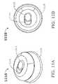
- FIGS. 11A & 11Bare isometric and top views, respectively, of another embodiment of a heart sound signal acquirer for the auscultation device of FIG. 1 .
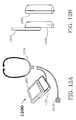
- FIGS. 12A & 12Bshow an isometric and two side views of another embodiment of the auscultation device of FIG. 1 .
- FIGS. 13 and 14illustrate two additional embodiments of the auscultation device of FIG. 1 .
- FIGS. 15 and 16show embodiments of the auscultation device of FIG. 1 wherein the heart sound signal acquirer is attached directly to the main body of the auscultation device.
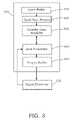
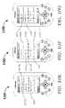
- FIG. 1is a block diagram showing one embodiment of an auscultation device 100 for analyzing and displaying heart sounds in accordance with the present invention.
- Device 100includes heart sound signal acquirer 110 , signal conditioner 120 , signal processor 130 , memory 140 , user interface 150 , video display 160 and audio input/output device 170 .
- Memory 140can be fixed or removal memory, and combinations thereof. Examples of suitable technologies for memory 140 include solid-state memory such as flash memory, or a hard disk drive.
- User interface 150can be a keypad, a keyboard, a thumbwheel, a joystick, and combinations thereof.
- Video display 160can be an LCD screen, or can be an LED display or a miniature plasma screen. It is also possible to combine video display 160 with user interface 150 by use of technologies such as a touch screen. Contrast and brightness control capability can also be added to display 160 .
- Audio input/output (I/O) device 170includes a microphone, and speakers, earphones or headphones, any of which can be internal or external with respect to device 100 . It is also possible to use wireless audio I/O devices such as a Bluetooth-based headset. Volume control of device 170 can also be provided.
- FIG. 2is a block diagram illustrating heart sound signal acquirer 110 in greater detail.
- Acquirer 110includes an acoustic sensor 210 and a preamplifier 215 which are coupled to signal conditioner 120 .
- sensor 210is a unidirectional microphone housed in a chest piece assembly.
- Preamplifier 215is solid-state and provides pre-amplified heart sounds to signal conditioner 120 .
- FIG. 3is a detailed block diagram illustrating heart sound signal conditioner 120 which includes an input buffer 310 , one or more band pass filter(s) 320 , a variable gain amplifier 330 , a gain controller 340 and an output buffer 350 .
- Output buffer 350is coupled to signal processor 130 which in turn is coupled to gain controller 340 .
- filter 320is a 4 th order Butterworth pass band of 5 Hz to 2 kHz which limits the analysis of the heart sound signal to frequencies less than 2 kHz, thereby ensuring that all frequencies of the heart sounds are faithfully captured and at the same time eliminating noise sources that typically exist beyond the pass band of filter 320 .
- Variable gain amplifier 330 of signal conditioner 120serves to vary the signal gain based on a user-selectable input parameter, and also serves to ensure enhanced signal quality and improved signal to noise ratio.
- the conditioned heart sound signal after filtering and amplificationis then provided to signal processor 350 via output buffer 350 .
- FIG. 4is a flow diagram illustrating an exemplary “Decomposition” of heart sound signals by one embodiment of signal processor 350 .
- heart sound signalsare retrieved from input buffer 310 .
- the usercan select Visual Display mode and/or Audio Playback mode as shown in step 410 .
- Two sets of filters of different frequencies pass bandspertain to two modes of operation, namely, a “Bell” mode and a “Diaphragm” mode. These two operational modes emulate the respective functions of a combined Bell/Diaphragm head found in traditional acoustic (non-electronic) stethoscopes that many experienced clinicians are accustomed to using. These two sets of filters pertain to audio filtering as shown in steps 460 and 465 , as well as video filtering for subsequent visual display on display 160 . Depending on the user selection between audio playback mode and visual display mode, the pertinent set of audio or video filters is enabled.
- the user's visual analysis of the decomposed the heart soundsis based on the Bell or Diaphragm mode selected through user interface 150 .
- FIG. 10Fwhich shows an exemplary “Bell” Visual Display mode
- the composite heart sound signalwhich is between 0-300 Hertz is decomposed into two component frequency ranges; a low frequency component between 0-150 Hertz and a high frequency component between 100-300 Hertz (steps 420 , 425 ).
- the low frequency componentshighlights S 1 , S 2 , S 3 , S 4 , and low frequency murmurs, while the high frequency components highlights S 1 , S 2 , low frequency murmurs (prominent) and medium frequency murmurs (suppressed).
- FIG. 10Dwhich illustrates a “Diaphragm” Visual Display mode
- the composite heart sound signal which is between 60-800 Hertzis also decomposed into two component frequency ranges, a low frequency component between 60-300 Hertz and a high frequency component between 250-800 Hertz (steps 430 , 435 ).
- the low frequency componentshighlighting the S 1 , S 2 , medium frequency murmurs (prominent) and low frequency murmurs (suppressed).
- the high frequency componentshighlighting the medium frequency murmurs and high frequency murmurs.
- the frequencies captured in “Bell” modeinclude the complete range of Bell frequencies.
- the frequencies captured in “Diaphragm” modeinclude the complete range of the Diaphragm frequencies.
- display 160e.g., an LCD display
- audio output device 170e.g., a set of headphones
- DACdigital-to-analog conversion
- both visual and auditory representations of the heart sounds as experienced by the userare synchronized.
- the sensor headhas two opposing sensors (not shown), i.e., a Bell-side sensor and a Diaphragm-side sensor, like a traditional acoustic stethoscope. Accordingly, instead of the user manually selecting the Decomposition mode, device 100 automatically selects the appropriate decomposition mode by sensing whether the Bell side sensor or the Diaphragm side sensor of the sensor head is touching the chest wall of the patient and hence is generating a stronger heart sound signal. The heart sounds are then analyzed by the corresponding Bell or Diaphragm filters which are also automatically selected by processor 130 .
- heart signal acquirer 1110also includes a selector switch 1115 which the user can use to select from two or more pre-determined modes, e.g., a “Bell” mode or a “Diaphragm” mode, using a finger of the same hand that is hold signal acquirer 1110 against the chest wall of the patient. While an exemplary two-position slider switch assembly 1115 , 1116 is shown, it is understood that other selector switches are also possible, including push button switches, rocker switches and rotary switches. Switch 1115 can be located on the top of or on the side of signal acquirer 1110 .
- FIG. 5is a flow diagram illustrating heart sound signal audio playback as facilitated by the user inputting the “Playback” command using user interface 150 , such as a keypad (step 510 ).
- the usercan select “Normal” playback or “Stereophonic” playback (steps 520 , 530 ).
- the usercan also select “Bell” mode or “Diaphragm” mode (steps 550 , 570 ).
- display 160such as an LCD screen, shows the composite Bell waveform as well as the respective component low frequency and the high frequency waveforms.
- step 580when Diaphragm mode has been selected, display 160 such as an LCD screen, shows the composite Diaphragm waveform as well as the respective component low frequency and the high frequency waveforms.
- a vertical “Play” cursorscrolls across the three waveforms on display 160 synchronously with the audio playback described above, thereby ensuring that the user can visually see on display 160 what he/she is hearing via audio output device 170 .
- FIG. 6is a flow diagram illustrating the “Zoom” command for video display 160 of auscultation device 100 .
- the useris able to Enlarge or Reduce the heart sound waveforms along the horizontal-axis, i.e., along the time domain, displayed on video display 160 (step 610 ).
- the Enlarge key presswill have no effect once the maximum Enlargement has been reached (steps 620 , 630 , 640 ).
- the Reduce key presswill have no effect once the maximum Reduction has been reached (steps 650 , 670 , 680 ).
- FIG. 7is a flow diagram illustrating soft “Calipers” for time measures of heart sound waveforms.
- the useractivates the Caliper function on video display 160 by pressing keys on user interface 150 , causing soft calipers to appear on display 160 as a pair of lines (step 705 ).
- the time widths enclosed by the respective calipersalso appear on display 160 .
- X calipersa pair of vertical calipers appears.
- X calipersallow the user to make accurate measurements of the time periods of the different heart sound phases.
- FIG. 10Fif “Y” calipers are selected, a pair of horizontal calipers appears. Y calipers allow the user to ascertain the murmur grades, whenever murmurs are detected in the heart sounds.
- the useris able to ascertain pathologic heart conditions using device 100 because of most conditions can be associated with their respective characteristic frequencies and amplitude durations. For example under the right conditions, mitral value regurgitation can be diagnosed with approximately 60% certainty.
- the caliperscan be repositioned by moving left or right relative to its current position. For example, as shown in steps 710 , 714 , calipers can be repositioned to the left until the calipers are at the end of the page, thereby causing the “previous page” of the heart sound waveforms to appear on display 160 (step 718 ). Alternatively, the calipers can be repositioned to the right until the calipers are at the end of the page (steps 740 , 744 ), thereby causing the “next page” of the heart sound waveforms to appear on display 160 (step 748 ). Other display positioning modes are possible. For example, it is also possible to move the display window by partial page increments or portions thereof.
- the calipers on display 160can be resized by expanding or reducing the size of the calipers.
- the caliperscan be enlarged until a maximum size is reached, and further key presses will no longer have any effect (step 728 ).
- the caliperscan be reduced until a minimum size is reached, and further key presses will no longer have any effect (steps 730 , 734 , 738 ).
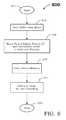
- FIG. 8is a flow diagram illustrating the storage of heart sound signals acquired by auscultation device 100 .
- the userselects the “Save” function by pressing keys on user interface 150 , causing device 100 to download the heart sound signal, and associated patient identification and any annotation into a removable or an external memory device (step 820 ).
- the patient ID and annotationscan be added using voice recordings thereby minimizing the need for additional keystrokes.
- the local memory of device 100can now be freed up for recording new heart sound signals (steps 830 , 840 ).
- speech recognition technologyknown to one skilled in the art can be incorporated into device 100 , enabling a textual record of the patent identification and annotations to be included instead or in addition to an audio recording. Speech recognition capability can also be used to activate the various functions of device 100 , thereby resulting in a user-friendly and relatively hands-free auscultation device. Accuracy and/or efficiency of speech recognition can be increased by limiting the vocabulary and/or training the synthesizer to recognize the user's vocal characteristics.
- device 100can ask a user whether device 100 should be sensing in “Bell” or “Diaphragm” mode, or to inform the user that an invalid command/mode has been selected.
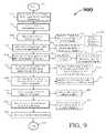
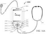
- FIG. 9the flowchart of FIG. 9 and the screenshots of FIGS. 10A-10G are now used to illustrate a typical sequence of the various functions that a user may activate while using auscultation device 100 to diagnose the heart sounds of a patient.
- a heart sound signal acquirer 110e.g., a microphone embedded in a chestpiece
- audio input device 170e.g., earphones
- FIG. 10Bshows device 100 during the “Power On” cycle
- FIG. 10Ashows battery level 1011 upon completion of the “Power On” which enables the user to keep track of the power needs of device 100 .
- device 100goes into a sleep mode if there are no key presses after a timeout period, e.g., after two minutes. While in this sleep mode, any key press causes device 100 to return to the last state of operation.
- the userpre-selects a suitable duration of heart diagnosis, e.g., X seconds, of heart sound signals to be acquired (step 910 ).
- device 100displays function “Acquire” 1013 and enables the user to make a voice recording of the associated patient information including patient ID (step 920 ).
- the userplaces chestpiece 110 on the patient's chest (step 930 ), which causes device 100 to output the heart sound 1064 on video display 160 as shown in FIG. 10C (device response 935 ).
- the “Original” heart sound 1064enables the user to interpret the graphical representation of the complete heart waveforms, thereby providing the user with a general idea of the condition of the patient's heart.
- device 100initially displays the default audio volume level as an adjustable “Speaker” icon 1012 , the default signal gain level as a “Dial” icon 1016 , and the default zoom as a “Percentage” icon 1015 on video display 160 .
- step 400the user selects “Bell” or “Diaphragm” mode by pressing “Mode Select” key 1053 , thereby causing device 100 to indicate the appropriate mode, in this example, “Diaphragm” 1014 , on video display 160 (device response 942 ).
- “Function Select” key 1052to activate the “Decompose” function (step 940 ), which is followed by a lapse of X seconds, original heart sound 1067 , and decomposed low frequency heart sound 1066 and high frequency heart sound 1065 are displayed by device 100 (device responses 944 , 946 ).
- the decomposed heart sounds 1065 , 1066enable the user to identify the various heart sound phases and also to detect the presence of heart murmurs.
- the userBy manipulating the “Play/Pause” key 1059 as shown in step 500 , the user causes device 100 to playback and/or record the heart sound signal, and also enables the user to select between “Normal” and “Stereophonic” playback modes (device response 955 ).
- step 600by manipulating Function Select key 1054 and “Directional” keys 1055 , 1057 (step 600 ), the user is able to “Zoom In” and “Zoom Out” on the heart sounds in the time domain, i.e., along the X-axis of display 160 (device response 965 ), thereby allowing the user to observe a closer expanded view of the heart sounds.
- step 700by activating “X-Calipers” 1072 a , 1072 b , device 100 enables the user to make more accurate time measurements of the heart sound phases (device response 975 ). This ability to zoom in/out and to measure the heart sounds in the time domain is particularly important when one of more of the heart sound phases exceed a particular “normal” time limit, and is indicative of a pathological condition.
- FIG. 10Gdepicts device 100 during playback of the heart sounds, as indicated by “Playback” mode 1017 on display 160 .
- Note vertical line cursor 1073scrolls across display 160 during playback, synchronizing the video display with the audio playback of the heart sounds, and enabling the user to visually observing on display 160 what he or she is hearing on audio output device 170 .
- the userAfter playback, the user has the option of saving the heart sounds in memory 140 for future analysis before initiating a new recording by pressing “Home” key 1051 (step 800 and device response 985 ).
- the usercan now initiate a new heart sound recording by pressing Function Select key 1054 as shown in step 900 .
- FIG. 12Aillustrates another embodiment 1200 in which heart sound acquirer 1210 and display 1260 are both coupled to audio input device 1270 .
- FIG. 12Bshow side views of the “open” and “close” positions, respectively, of device 1200 .
- the “power-on” function of device 1200can be activated by sliding open device 1200 which simultaneously exposes user interface 1250 . Conversely, sliding close device 1200 conceals user interface 1250 and powers-down device 1200 .
- FIG. 13is an isometric view of an additional embodiment of device 100 .
- Device 1300includes a display 1360 which can be a touch-screen large enough to incorporate all or a portion of the user interface for device 1300 . It is possible for device 1300 to be worn like a watch on the wrist of the user by adding a wrist strap.
- FIG. 14is an isometric view of yet another embodiment of device 100 .
- Device 1400is a compact version with display 1460 supported by audio input device 1470 .
- display 1460 of device 1400can be conveniently flipped open resulting in a hands-free display capability.
- heart sound acquirer 1410is attached to display 1460 .
- device 100can also be used to sense and record lung sounds, including the higher frequency ranges associated with pulmonary problems such as wheezing.
- device 100provides many advantages over the existing auscultatory devices, including ease of use, accuracy, portability, cost-effectiveness and ease of sterilization and maintenance.
Landscapes
- Health & Medical Sciences (AREA)
- Engineering & Computer Science (AREA)
- Life Sciences & Earth Sciences (AREA)
- Biomedical Technology (AREA)
- Medical Informatics (AREA)
- Public Health (AREA)
- General Health & Medical Sciences (AREA)
- Heart & Thoracic Surgery (AREA)
- Surgery (AREA)
- Physics & Mathematics (AREA)
- Veterinary Medicine (AREA)
- Animal Behavior & Ethology (AREA)
- Molecular Biology (AREA)
- Acoustics & Sound (AREA)
- Business, Economics & Management (AREA)
- Primary Health Care (AREA)
- General Business, Economics & Management (AREA)
- Cardiology (AREA)
- Epidemiology (AREA)
- Physiology (AREA)
- Computer Networks & Wireless Communication (AREA)
- Biophysics (AREA)
- Pathology (AREA)
- Measuring Pulse, Heart Rate, Blood Pressure Or Blood Flow (AREA)
- Measuring And Recording Apparatus For Diagnosis (AREA)
Abstract
Description
Claims (21)
Priority Applications (2)
| Application Number | Priority Date | Filing Date | Title |
|---|---|---|---|
| US11/740,906US7806833B2 (en) | 2006-04-27 | 2007-04-26 | Systems and methods for analysis and display of heart sounds |
| US12/109,346US20080273709A1 (en) | 2006-04-27 | 2008-04-25 | Systems and methods for tuning, analysis and display of heart sounds |
Applications Claiming Priority (4)
| Application Number | Priority Date | Filing Date | Title |
|---|---|---|---|
| IN772CH2006 | 2006-04-27 | ||
| IN772/CHE/2006 | 2006-04-27 | ||
| US83338506P | 2006-07-25 | 2006-07-25 | |
| US11/740,906US7806833B2 (en) | 2006-04-27 | 2007-04-26 | Systems and methods for analysis and display of heart sounds |
Related Child Applications (1)
| Application Number | Title | Priority Date | Filing Date |
|---|---|---|---|
| US12/109,346Continuation-In-PartUS20080273709A1 (en) | 2006-04-27 | 2008-04-25 | Systems and methods for tuning, analysis and display of heart sounds |
Publications (2)
| Publication Number | Publication Date |
|---|---|
| US20090012415A1 US20090012415A1 (en) | 2009-01-08 |
| US7806833B2true US7806833B2 (en) | 2010-10-05 |
Family
ID=38656219
Family Applications (2)
| Application Number | Title | Priority Date | Filing Date |
|---|---|---|---|
| US11/740,906Expired - Fee RelatedUS7806833B2 (en) | 2006-04-27 | 2007-04-26 | Systems and methods for analysis and display of heart sounds |
| US12/109,346AbandonedUS20080273709A1 (en) | 2006-04-27 | 2008-04-25 | Systems and methods for tuning, analysis and display of heart sounds |
Family Applications After (1)
| Application Number | Title | Priority Date | Filing Date |
|---|---|---|---|
| US12/109,346AbandonedUS20080273709A1 (en) | 2006-04-27 | 2008-04-25 | Systems and methods for tuning, analysis and display of heart sounds |
Country Status (4)
| Country | Link |
|---|---|
| US (2) | US7806833B2 (en) |
| EP (1) | EP2010059A4 (en) |
| JP (1) | JP5586947B2 (en) |
| WO (1) | WO2007127386A2 (en) |
Cited By (5)
| Publication number | Priority date | Publication date | Assignee | Title |
|---|---|---|---|---|
| US20090227888A1 (en)* | 2005-12-20 | 2009-09-10 | Smart Valley Software Oy | Method and an apparatus for measuring and analyzing movements of a human or an animal using sound signals |
| US20110087079A1 (en)* | 2008-06-17 | 2011-04-14 | Koninklijke Philips Electronics N.V. | Acoustical patient monitoring using a sound classifier and a microphone |
| US8491488B1 (en) | 2010-10-01 | 2013-07-23 | Blaufuss Medical Multimedia Laboratories, LLC | Method and system for identifying cardiopulmonary findings by using a heart and lung sounds builder |
| US9226725B2 (en) | 2012-05-17 | 2016-01-05 | Industrial Technology Research Institute | Physiological signals sensing structure, stethoscope therewith and manufacturing method thereof |
| US10039520B2 (en) | 2005-04-13 | 2018-08-07 | Aum Cardiovascular, Inc | Detection of coronary artery disease using an electronic stethoscope |
Families Citing this family (41)
| Publication number | Priority date | Publication date | Assignee | Title |
|---|---|---|---|---|
| US8920343B2 (en) | 2006-03-23 | 2014-12-30 | Michael Edward Sabatino | Apparatus for acquiring and processing of physiological auditory signals |
| US8212183B2 (en)* | 2006-12-26 | 2012-07-03 | Intel Corporation | Method and apparatus for utilizing thermal energy generated by medical diagnostic devices |
| KR100771450B1 (en)* | 2007-02-05 | 2007-10-31 | 동진메디칼 주식회사 | Remote Stethoscope System Using Wired / Wireless Network |
| US12324657B2 (en) | 2007-11-28 | 2025-06-10 | Intervet Inc. | System and method for diagnosis of bovine diseases using auscultation analysis |
| US11389080B2 (en)* | 2007-11-28 | 2022-07-19 | Intervet Inc. | System and method for diagnosis of bovine diseases using auscultation analysis |
| BRPI0913474A8 (en)* | 2008-09-10 | 2016-11-29 | Koninklijke Philips Electronics Nv | SYSTEM FOR LOCATION OF A SOUND SOURCE, STETHOSCOPE, RECEIVER PART CONNECTED TO THE SYSTEM AND METHOD FOR LOCATION OF A SOUND SOURCE |
| US10064580B2 (en) | 2008-11-07 | 2018-09-04 | Intervet Inc. | System and method for determining antibiotic effectiveness in respiratory diseased animals using auscultation analysis |
| BR112012005854A2 (en)* | 2009-09-16 | 2017-05-02 | 3M Innovative Properties Company | TELEMEDICINE SYSTEMS, ELECTRONIC STESTOCOPE AND BIOACOUSTIC SENSOR |
| BR112012014295A2 (en)* | 2009-12-18 | 2017-10-24 | Koninl Philips Electronics Nv | signal processing apparatus, method of operating a signal processing apparatus and computer program product |
| US9480400B2 (en) | 2010-02-01 | 2016-11-01 | 3M Innovative Properties Company | Electronic stethoscope system for telemedicine applications |
| US9204856B2 (en)* | 2010-02-01 | 2015-12-08 | 3M Innovative Properties Company | Electronic stethoscope system for telemedicine applications |
| EP2608714A4 (en)* | 2010-08-25 | 2017-03-08 | Diacoustic Medical Devices (Pty) Ltd | A system and method for classifying a heart sound |
| US20120209131A1 (en)* | 2011-02-11 | 2012-08-16 | AventuSoft, LLC | Method and System of a Cardio-acoustic Classification system for Screening, Diagnosis and Monitoring of Cardiovascular Conditions |
| JP6076364B2 (en) | 2011-10-28 | 2017-02-08 | コーニンクレッカ フィリップス エヌ ヴェKoninklijke Philips N.V. | Apparatus and method for processing heart sounds for auscultation |
| US8666484B2 (en)* | 2011-11-25 | 2014-03-04 | Persyst Development Corporation | Method and system for displaying EEG data |
| US9055927B2 (en)* | 2011-11-25 | 2015-06-16 | Persyst Development Corporation | User interface for artifact removal in an EEG |
| US10402782B2 (en) | 2012-04-16 | 2019-09-03 | Airstrip Ip Holdings, Llc | Systems and methods for and displaying patient data |
| CA2869632C (en)* | 2012-04-16 | 2021-05-25 | Airstrip Ip Holdings, Llc | Systems and methods for displaying patient data |
| US9521956B2 (en)* | 2012-06-05 | 2016-12-20 | 3M Innovative Properties Company | Enhanced auscultatory sensor and analysis for patient diagnosis |
| US20140128755A1 (en)* | 2012-11-08 | 2014-05-08 | Quinn Snyder | Pulse Detecting Device and Method |
| CN103120592A (en)* | 2012-11-29 | 2013-05-29 | 中国人民解放军第四军医大学 | Heart sound electronic auscultation and intelligent health analysis system |
| US9042568B2 (en)* | 2012-12-11 | 2015-05-26 | Barry Poplaw | Portable smart stethoscope formed of smart mobile device and casing assembly |
| EP2953544B1 (en) | 2013-02-06 | 2019-05-08 | Intervet Inc. | System for determining antibiotic effectiveness in respiratory diseased using auscultation analysis |
| ITTO20130496A1 (en)* | 2013-06-17 | 2014-12-18 | St Microelectronics Srl | MOBILE DEVICE FOR AN ELECTRONIC STETHOSCOPE INCLUDING AN ELECTRONIC MICROPHONE AND A UNIT OF DETECTION OF THE POSITION OF THE MOBILE DEVICE |
| CN103479386B (en)* | 2013-09-02 | 2015-09-30 | 无锡慧思顿科技有限公司 | A kind of system based on sound transducer identifying and diagnosing rheumatic heart disease |
| US9241673B2 (en)* | 2013-09-30 | 2016-01-26 | Cyberonics, Inc. | Systems and methods for validating monitoring device placement and locations |
| TW201513833A (en)* | 2013-10-11 | 2015-04-16 | Euclid Technology Co Ltd | Measuring apparatus |
| WO2015094426A1 (en)* | 2013-12-22 | 2015-06-25 | Bose Swaralipy | A device for monitoring, recording and transmitting input received from a medical diagnostics instrument |
| US11406347B2 (en)* | 2014-10-23 | 2022-08-09 | Medtronic, Inc. | Acoustic monitoring to detect medical condition |
| US20170086778A1 (en)* | 2015-09-29 | 2017-03-30 | International Business Machines Corporation | Capture and analysis of body sounds |
| US10867019B2 (en)* | 2015-10-21 | 2020-12-15 | Nec Corporation | Personal authentication device, personal authentication method, and personal authentication program using acoustic signal propagation |
| CN105455842A (en)* | 2015-12-24 | 2016-04-06 | 香港一方智能医疗科技有限公司 | Intelligent auscultation system |
| JP6709657B2 (en)* | 2016-03-28 | 2020-06-17 | パイオニア株式会社 | Auscultation device and electronic equipment |
| CN109313931A (en) | 2016-05-11 | 2019-02-05 | 泰拓卡尔有限公司 | System, method and computer program product for providing feedback related to medical examination |
| CN111166320A (en)* | 2019-12-31 | 2020-05-19 | 中科彭州智慧产业创新中心有限公司 | Electrode position adjustable developments electrocardio monitoring pectoral girdle |
| CN112022200A (en)* | 2020-09-18 | 2020-12-04 | 湖南万脉医疗科技有限公司 | Multifunctional equipment for visual heart sound identification |
| JP7295368B2 (en)* | 2020-12-31 | 2023-06-21 | Yanchers株式会社 | Auscultation sound analysis system |
| US20240423579A1 (en)* | 2021-10-26 | 2024-12-26 | Sparrow Acoustics Inc. | Method and an electronic device for processing a waveform |
| CN115736938A (en)* | 2022-11-17 | 2023-03-07 | 东南大学 | Multi-mode physiological signal acquisition device |
| US20240424307A1 (en)* | 2023-06-22 | 2024-12-26 | Pacesetter, Inc. | Method and system for monitoring heart function based on electromechanical activation time |
| WO2025019404A2 (en)* | 2023-07-17 | 2025-01-23 | University Of Pittsburgh - Of The Commonwealth System Of Higher Education | Cardiac auscultation using earphones |
Citations (27)
| Publication number | Priority date | Publication date | Assignee | Title |
|---|---|---|---|---|
| US3799147A (en)* | 1972-03-23 | 1974-03-26 | Directors University Cincinnat | Method and apparatus for diagnosing myocardial infarction in human heart |
| US3878832A (en)* | 1973-05-14 | 1975-04-22 | Palo Alto Medical Research Fou | Method and apparatus for detecting and quantifying cardiovascular murmurs and the like |
| US4182315A (en)* | 1977-07-21 | 1980-01-08 | Diamond George A | Apparatus and method for detection of body tissue movement |
| US4672977A (en) | 1986-06-10 | 1987-06-16 | Cherne Industries, Inc. | Lung sound cancellation method and apparatus |
| US5012815A (en) | 1989-02-02 | 1991-05-07 | Yale University | Dynamic spectral phonocardiograph |
| US5213108A (en) | 1988-02-04 | 1993-05-25 | Blood Line Technology, Inc. | Visual display stethoscope |
| US6278890B1 (en) | 1998-11-09 | 2001-08-21 | Medacoustics, Inc. | Non-invasive turbulent blood flow imaging system |
| US6368283B1 (en)* | 2000-09-08 | 2002-04-09 | Institut De Recherches Cliniques De Montreal | Method and apparatus for estimating systolic and mean pulmonary artery pressures of a patient |
| US20020151812A1 (en)* | 2001-04-11 | 2002-10-17 | Cardiac Pacemakers, Inc. | Apparatus and method for outputting heart sounds |
| US6512830B1 (en)* | 1995-02-09 | 2003-01-28 | Meditron As | Auscultation apparatus |
| US6520924B2 (en)* | 2000-11-16 | 2003-02-18 | Byung Hoon Lee | Automatic diagnostic apparatus with a stethoscope |
| US20030045805A1 (en) | 2001-08-30 | 2003-03-06 | Medtronic, Inc. | Ischemia detection |
| US20030083582A1 (en) | 2001-10-31 | 2003-05-01 | Robert Hirsh | Non-invasive method and device to monitor cardiac parameters |
| US20030093002A1 (en)* | 2001-11-13 | 2003-05-15 | Kuo Terry B.J. | Function indicator for autonomic nervous system based on phonocardiogram |
| US20030163058A1 (en) | 2001-10-11 | 2003-08-28 | Osypka Markus J. | Method and apparatus for determining the left-ventricular ejection time TLVE of a heart of a subject |
| US20040028236A1 (en)* | 2002-08-08 | 2004-02-12 | Chelen William E. | Time and frequency windowed pocket cardiac stethoscope |
| US20040106961A1 (en)* | 2002-12-02 | 2004-06-03 | Siejko Krzysztof Z. | Method and apparatus for phonocardiographic image acquisition and presentation |
| US20040260188A1 (en)* | 2003-06-17 | 2004-12-23 | The General Hospital Corporation | Automated auscultation system |
| US6910005B2 (en) | 2000-06-29 | 2005-06-21 | Koninklijke Philips Electronics N.V. | Recording apparatus including quality test and feedback features for recording speech information to a subsequent off-line speech recognition |
| WO2005123180A1 (en) | 2004-06-17 | 2005-12-29 | St. Jude Medical Ab | Detection and/or monitoring of diastolic heart failure |
| US20060173336A1 (en) | 2004-12-10 | 2006-08-03 | Goubergen Herman V | Method of selecting part of a run of echocardiography images |
| US7174203B2 (en) | 2004-11-18 | 2007-02-06 | Inovise Medical, Inc. | Method and system relating to monitoring and characterizing heart condition |
| US20070043299A1 (en) | 2005-08-19 | 2007-02-22 | Cardiac Pacemakers, Inc. | Tracking progression of congestive heart failure via a force-frequency relationship |
| US7300407B2 (en) | 2003-11-10 | 2007-11-27 | Zargis Medical Corporation | Handheld auscultatory scanner with synchronized display of heart sounds |
| US20080039733A1 (en) | 2006-08-08 | 2008-02-14 | Kamil Unver | Systems and methods for calibration of heart sounds |
| US20080154144A1 (en) | 2006-08-08 | 2008-06-26 | Kamil Unver | Systems and methods for cardiac contractility analysis |
| US20080167566A1 (en) | 2006-08-08 | 2008-07-10 | Kamil Unver | Systems and methods for determining systolic time intervals |
Family Cites Families (7)
| Publication number | Priority date | Publication date | Assignee | Title |
|---|---|---|---|---|
| CA1143014A (en)* | 1980-04-24 | 1983-03-15 | Her Majesty The Queen, In Right Of Canada, As Represented By The Minister Of National Defence | Portable digital heart rate meter/ stethoscope |
| CA1198806A (en)* | 1982-11-24 | 1985-12-31 | Her Majesty The Queen, In Right Of Canada, As Represented By The Minister Of National Defence | Heart rate detector |
| US5010889A (en)* | 1988-02-04 | 1991-04-30 | Bloodline Technology | Intelligent stethoscope |
| WO1994013206A1 (en)* | 1992-12-07 | 1994-06-23 | Curatechnologies Inc. | Electronic stethoscope |
| US5913826A (en)* | 1996-06-12 | 1999-06-22 | K-One Technologies | Wideband external pulse cardiac monitor |
| US6438238B1 (en)* | 2000-07-14 | 2002-08-20 | Thomas F. Callahan | Stethoscope |
| US7300405B2 (en)* | 2003-10-22 | 2007-11-27 | 3M Innovative Properties Company | Analysis of auscultatory sounds using single value decomposition |
- 2007
- 2007-04-26USUS11/740,906patent/US7806833B2/ennot_activeExpired - Fee Related
- 2007-04-27EPEP07794393Apatent/EP2010059A4/ennot_activeWithdrawn
- 2007-04-27WOPCT/US2007/010272patent/WO2007127386A2/enactiveApplication Filing
- 2007-04-27JPJP2009507826Apatent/JP5586947B2/ennot_activeExpired - Fee Related
- 2008
- 2008-04-25USUS12/109,346patent/US20080273709A1/ennot_activeAbandoned
Patent Citations (28)
| Publication number | Priority date | Publication date | Assignee | Title |
|---|---|---|---|---|
| US3799147A (en)* | 1972-03-23 | 1974-03-26 | Directors University Cincinnat | Method and apparatus for diagnosing myocardial infarction in human heart |
| US3878832A (en)* | 1973-05-14 | 1975-04-22 | Palo Alto Medical Research Fou | Method and apparatus for detecting and quantifying cardiovascular murmurs and the like |
| US4182315A (en)* | 1977-07-21 | 1980-01-08 | Diamond George A | Apparatus and method for detection of body tissue movement |
| US4672977A (en) | 1986-06-10 | 1987-06-16 | Cherne Industries, Inc. | Lung sound cancellation method and apparatus |
| US5213108A (en) | 1988-02-04 | 1993-05-25 | Blood Line Technology, Inc. | Visual display stethoscope |
| US5012815A (en) | 1989-02-02 | 1991-05-07 | Yale University | Dynamic spectral phonocardiograph |
| US6512830B1 (en)* | 1995-02-09 | 2003-01-28 | Meditron As | Auscultation apparatus |
| US6278890B1 (en) | 1998-11-09 | 2001-08-21 | Medacoustics, Inc. | Non-invasive turbulent blood flow imaging system |
| US6910005B2 (en) | 2000-06-29 | 2005-06-21 | Koninklijke Philips Electronics N.V. | Recording apparatus including quality test and feedback features for recording speech information to a subsequent off-line speech recognition |
| US6368283B1 (en)* | 2000-09-08 | 2002-04-09 | Institut De Recherches Cliniques De Montreal | Method and apparatus for estimating systolic and mean pulmonary artery pressures of a patient |
| US6520924B2 (en)* | 2000-11-16 | 2003-02-18 | Byung Hoon Lee | Automatic diagnostic apparatus with a stethoscope |
| US20020151812A1 (en)* | 2001-04-11 | 2002-10-17 | Cardiac Pacemakers, Inc. | Apparatus and method for outputting heart sounds |
| US20050137490A1 (en)* | 2001-04-11 | 2005-06-23 | Cardiac Pacemakers, Inc. | Apparatus and method for outputting heart sounds |
| US20030045805A1 (en) | 2001-08-30 | 2003-03-06 | Medtronic, Inc. | Ischemia detection |
| US20030163058A1 (en) | 2001-10-11 | 2003-08-28 | Osypka Markus J. | Method and apparatus for determining the left-ventricular ejection time TLVE of a heart of a subject |
| US20030083582A1 (en) | 2001-10-31 | 2003-05-01 | Robert Hirsh | Non-invasive method and device to monitor cardiac parameters |
| US20030093002A1 (en)* | 2001-11-13 | 2003-05-15 | Kuo Terry B.J. | Function indicator for autonomic nervous system based on phonocardiogram |
| US20040028236A1 (en)* | 2002-08-08 | 2004-02-12 | Chelen William E. | Time and frequency windowed pocket cardiac stethoscope |
| US20040106961A1 (en)* | 2002-12-02 | 2004-06-03 | Siejko Krzysztof Z. | Method and apparatus for phonocardiographic image acquisition and presentation |
| US20040260188A1 (en)* | 2003-06-17 | 2004-12-23 | The General Hospital Corporation | Automated auscultation system |
| US7300407B2 (en) | 2003-11-10 | 2007-11-27 | Zargis Medical Corporation | Handheld auscultatory scanner with synchronized display of heart sounds |
| WO2005123180A1 (en) | 2004-06-17 | 2005-12-29 | St. Jude Medical Ab | Detection and/or monitoring of diastolic heart failure |
| US7174203B2 (en) | 2004-11-18 | 2007-02-06 | Inovise Medical, Inc. | Method and system relating to monitoring and characterizing heart condition |
| US20060173336A1 (en) | 2004-12-10 | 2006-08-03 | Goubergen Herman V | Method of selecting part of a run of echocardiography images |
| US20070043299A1 (en) | 2005-08-19 | 2007-02-22 | Cardiac Pacemakers, Inc. | Tracking progression of congestive heart failure via a force-frequency relationship |
| US20080039733A1 (en) | 2006-08-08 | 2008-02-14 | Kamil Unver | Systems and methods for calibration of heart sounds |
| US20080154144A1 (en) | 2006-08-08 | 2008-06-26 | Kamil Unver | Systems and methods for cardiac contractility analysis |
| US20080167566A1 (en) | 2006-08-08 | 2008-07-10 | Kamil Unver | Systems and methods for determining systolic time intervals |
Non-Patent Citations (5)
| Title |
|---|
| "International Search Report and the Written Opinion of the International Searching Authority", Application No. PCT/US06/12611, mailed Sep. 19, 2007. |
| "International Search Report and the Written Opinion of the International Searching Authority", Application No. PCT/US07/17608, mailed Jan. 28, 2008. |
| ISA/KR, PCT International Search Report and Written Opinion, Application No. PCT/US2008/086493, dated Apr. 23, 2009, 9 pages. |
| ISA/US, PCT International Search Report and Written Opinion, Application No. PCT/US2007/010272, dated Oct. 14, 2008, 7 pages. |
| Stefadouros, M.D., Miltiadis A. and Calhoun Witham, M.D., "Systolic Time Intervals by Echocardiography," Circulation Journal of the American Heart Association; 1975, vol. 51, pp. 114-117. |
Cited By (8)
| Publication number | Priority date | Publication date | Assignee | Title |
|---|---|---|---|---|
| US10039520B2 (en) | 2005-04-13 | 2018-08-07 | Aum Cardiovascular, Inc | Detection of coronary artery disease using an electronic stethoscope |
| US20090227888A1 (en)* | 2005-12-20 | 2009-09-10 | Smart Valley Software Oy | Method and an apparatus for measuring and analyzing movements of a human or an animal using sound signals |
| US8540650B2 (en)* | 2005-12-20 | 2013-09-24 | Smart Valley Software Oy | Method and an apparatus for measuring and analyzing movements of a human or an animal using sound signals |
| US20110087079A1 (en)* | 2008-06-17 | 2011-04-14 | Koninklijke Philips Electronics N.V. | Acoustical patient monitoring using a sound classifier and a microphone |
| US10269228B2 (en)* | 2008-06-17 | 2019-04-23 | Koninklijke Philips N.V. | Acoustical patient monitoring using a sound classifier and a microphone |
| US8491488B1 (en) | 2010-10-01 | 2013-07-23 | Blaufuss Medical Multimedia Laboratories, LLC | Method and system for identifying cardiopulmonary findings by using a heart and lung sounds builder |
| US8734358B1 (en) | 2010-10-01 | 2014-05-27 | Blaufuss Medical Multimedia Laboratories, LLC | Method and system for identifying cardiopulmonary findings by using a heart and lung sounds builder |
| US9226725B2 (en) | 2012-05-17 | 2016-01-05 | Industrial Technology Research Institute | Physiological signals sensing structure, stethoscope therewith and manufacturing method thereof |
Also Published As
| Publication number | Publication date |
|---|---|
| US20090012415A1 (en) | 2009-01-08 |
| US20080273709A1 (en) | 2008-11-06 |
| JP2009535106A (en) | 2009-10-01 |
| EP2010059A2 (en) | 2009-01-07 |
| WO2007127386A3 (en) | 2008-12-24 |
| JP5586947B2 (en) | 2014-09-10 |
| EP2010059A4 (en) | 2013-04-03 |
| WO2007127386A2 (en) | 2007-11-08 |
Similar Documents
| Publication | Publication Date | Title |
|---|---|---|
| US7806833B2 (en) | Systems and methods for analysis and display of heart sounds | |
| US12138106B2 (en) | Acquiring and processing acoustic energy emitted by at least one organ in a biological system | |
| US7300407B2 (en) | Handheld auscultatory scanner with synchronized display of heart sounds | |
| US9973847B2 (en) | Mobile device-based stethoscope system | |
| US20050157887A1 (en) | System for outputting acoustic signal from a stethoscope | |
| JP2008529696A (en) | Voice monitor | |
| CN102512138A (en) | Cardiac sound monitoring and early warning method | |
| CN107550515A (en) | Stethoscope system | |
| KR20150001009A (en) | Mobile terminal diagnosis system using portable wireless digital electronic stethoscope | |
| WO2000002486A1 (en) | Analytic stethoscope | |
| KR100416402B1 (en) | Potable diagnostic system for the heart and lung sounds | |
| KR100669532B1 (en) | USB Digital Stethoscope | |
| JP2001333899A (en) | Auscultating system and medium with recorded program which can be read by machine | |
| CN201039997Y (en) | Multifunctional electrostethophone | |
| KR200259030Y1 (en) | Electro-stethoscope | |
| CN203609444U (en) | Emergency department stethoscope | |
| KR200269579Y1 (en) | Potable diagnostic system for the heart and lung sounds | |
| US12380973B1 (en) | Systems and methods for dictation with a digital stethoscope | |
| KR200349837Y1 (en) | A digital stethoscope | |
| US20250311999A1 (en) | Electronic stethoscope | |
| KR20050087008A (en) | An electronic stethoscope | |
| KR20040053656A (en) | Electronics stethoscope |
Legal Events
| Date | Code | Title | Description |
|---|---|---|---|
| AS | Assignment | Owner name:HD MEDICAL GROUP LIMITED, AUSTRALIA Free format text:ASSIGNMENT OF ASSIGNORS INTEREST;ASSIGNORS:THIAGARAJAN, ARVIND;COFFMAN, DAMON J;TEO, TAT-JIN;REEL/FRAME:019567/0244;SIGNING DATES FROM 20070712 TO 20070716 Owner name:HD MEDICAL GROUP LIMITED, AUSTRALIA Free format text:ASSIGNMENT OF ASSIGNORS INTEREST;ASSIGNORS:THIAGARAJAN, ARVIND;COFFMAN, DAMON J;TEO, TAT-JIN;SIGNING DATES FROM 20070712 TO 20070716;REEL/FRAME:019567/0244 | |
| STCF | Information on status: patent grant | Free format text:PATENTED CASE | |
| FPAY | Fee payment | Year of fee payment:4 | |
| FEPP | Fee payment procedure | Free format text:MAINTENANCE FEE REMINDER MAILED (ORIGINAL EVENT CODE: REM.) | |
| AS | Assignment | Owner name:HD MEDICAL, INC., CALIFORNIA Free format text:ASSIGNMENT OF ASSIGNORS INTEREST;ASSIGNOR:HD MEDICAL GROUP LIMITED;REEL/FRAME:046234/0014 Effective date:20180628 | |
| FEPP | Fee payment procedure | Free format text:7.5 YR SURCHARGE - LATE PMT W/IN 6 MO, SMALL ENTITY (ORIGINAL EVENT CODE: M2555); ENTITY STATUS OF PATENT OWNER: SMALL ENTITY | |
| MAFP | Maintenance fee payment | Free format text:PAYMENT OF MAINTENANCE FEE, 8TH YR, SMALL ENTITY (ORIGINAL EVENT CODE: M2552); ENTITY STATUS OF PATENT OWNER: SMALL ENTITY Year of fee payment:8 | |
| FEPP | Fee payment procedure | Free format text:MAINTENANCE FEE REMINDER MAILED (ORIGINAL EVENT CODE: REM.); ENTITY STATUS OF PATENT OWNER: SMALL ENTITY | |
| LAPS | Lapse for failure to pay maintenance fees | Free format text:PATENT EXPIRED FOR FAILURE TO PAY MAINTENANCE FEES (ORIGINAL EVENT CODE: EXP.); ENTITY STATUS OF PATENT OWNER: SMALL ENTITY | |
| STCH | Information on status: patent discontinuation | Free format text:PATENT EXPIRED DUE TO NONPAYMENT OF MAINTENANCE FEES UNDER 37 CFR 1.362 | |
| FP | Lapsed due to failure to pay maintenance fee | Effective date:20221005 |