US7806724B2 - Coaxial connector for cable with a solid outer conductor - Google Patents
Coaxial connector for cable with a solid outer conductorDownload PDFInfo
- Publication number
- US7806724B2 US7806724B2US12/264,932US26493208AUS7806724B2US 7806724 B2US7806724 B2US 7806724B2US 26493208 AUS26493208 AUS 26493208AUS 7806724 B2US7806724 B2US 7806724B2
- Authority
- US
- United States
- Prior art keywords
- connector
- outer conductor
- grip
- connector body
- ring
- Prior art date
- Legal status (The legal status is an assumption and is not a legal conclusion. Google has not performed a legal analysis and makes no representation as to the accuracy of the status listed.)
- Active, expires
Links
Images


Classifications
- H—ELECTRICITY
- H01—ELECTRIC ELEMENTS
- H01R—ELECTRICALLY-CONDUCTIVE CONNECTIONS; STRUCTURAL ASSOCIATIONS OF A PLURALITY OF MUTUALLY-INSULATED ELECTRICAL CONNECTING ELEMENTS; COUPLING DEVICES; CURRENT COLLECTORS
- H01R9/00—Structural associations of a plurality of mutually-insulated electrical connecting elements, e.g. terminal strips or terminal blocks; Terminals or binding posts mounted upon a base or in a case; Bases therefor
- H01R9/03—Connectors arranged to contact a plurality of the conductors of a multiconductor cable, e.g. tapping connections
- H01R9/05—Connectors arranged to contact a plurality of the conductors of a multiconductor cable, e.g. tapping connections for coaxial cables
- H01R9/0521—Connection to outer conductor by action of a nut
- H—ELECTRICITY
- H01—ELECTRIC ELEMENTS
- H01R—ELECTRICALLY-CONDUCTIVE CONNECTIONS; STRUCTURAL ASSOCIATIONS OF A PLURALITY OF MUTUALLY-INSULATED ELECTRICAL CONNECTING ELEMENTS; COUPLING DEVICES; CURRENT COLLECTORS
- H01R4/00—Electrically-conductive connections between two or more conductive members in direct contact, i.e. touching one another; Means for effecting or maintaining such contact; Electrically-conductive connections having two or more spaced connecting locations for conductors and using contact members penetrating insulation
- H01R4/28—Clamped connections, spring connections
- H01R4/50—Clamped connections, spring connections utilising a cam, wedge, cone or ball also combined with a screw
- H01R4/5016—Clamped connections, spring connections utilising a cam, wedge, cone or ball also combined with a screw using a cone
- H01R4/5025—Clamped connections, spring connections utilising a cam, wedge, cone or ball also combined with a screw using a cone combined with a threaded ferrule operating in a direction parallel to the conductor
Definitions
- This inventionrelates to electrical cable connectors. More particularly, the invention relates to a solid outer conductor coaxial cable connector coupled to a coaxial cable by insertion of the cable end into a connector body bore.
- Coaxial cable connectorsare used, for example, in communication systems requiring a high level of precision and reliability.
- FIG. 1is a schematic isometric rear view of a first exemplary embodiment of a coaxial connector.
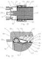
- FIG. 2is a schematic cross-section side view of the coaxial connector of FIG. 1 , with a section of coaxial cable attached.
- FIG. 3is a close-up view of area A of FIG. 2 .
- FIG. 4is a schematic cross-section side view of a first alternative embodiment coaxial connector, with a section of coaxial cable attached.
- FIG. 5is a close-up view of area B of FIG. 4 .
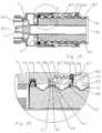
- FIG. 6is a schematic cross-section view of a second alternative embodiment coaxial connector, with a section of coaxial cable attached.
- FIG. 7is a close-up view of area C of FIG. 6 .
- FIG. 8is a close-up view of area D of FIG. 6 .
- FIG. 9is a schematic isometric view of the clamp ring of FIG. 6 .
- FIG. 10is a schematic cross-section view of a third alternative embodiment coaxial connector, with a section of coaxial cable attached.
- FIG. 11is a close-up view of area E of FIG. 10 .
- FIG. 12is a schematic isometric view of a spring contact.
- FIG. 13is a schematic isometric view of a grip ring with a solid cross-section and annular barbs.
- FIG. 14is a schematic isometric view of a grip ring with a horizontal V cross-section.
- FIG. 15is a schematic isometric view of a grip ring with a solid cross-section and helical barbs.
- FIG. 16is a schematic connector end side view of the grip ring of FIG. 15 .
- FIG. 17is a close-up cross section view along line B-B of FIG. 16 .
- FIG. 18is a schematic isometric view of a fourth alternative embodiment of a coaxial connector.
- FIG. 19is a schematic cross-section view of FIG. 18 .
- FIG. 20is a close-up view of area F of FIG. 19 .
- the inventorhas analyzed available solid outer conductor coaxial connectors and recognized the drawbacks of threaded inter-body connection(s), manual flaring installation procedures and crimp/compression coaxial connector designs.
- a coaxial connector 1has a connector body 3 with a connector body bore 5 .
- An insulator 7 seated within the connector body bore 5supports an inner contact 9 coaxial with the connector body bore 5 .
- the coaxial connector 1mechanically retains the outer conductor 11 of a coaxial cable 13 inserted into the cable end 15 of the connector body bore 5 via a grip surface 17 located on the inner diameter of a grip ring 19 .
- a spring contact 21 seated within the connector body bore 5makes circumferential contact with the outer conductor 11 , electrically coupling the outer conductor 11 across the connector body 3 to a connector interface 23 at the connector end 25 .
- the connector interface 23may be any desired standard or proprietary interface.
- each individual elementhas a cable end 15 side and a connector end 25 side, i.e. the sides of the respective element that are facing the respective cable end 15 and the connector end 25 of the coaxial connector 1 .
- the grip ring 19may be retained within the connector body bore 5 , for example seated within a grip ring groove 27 .
- the grip ring groove 27may be formed wherein the cable end grip ring groove 27 sidewall and/or bottom are surfaces of a clamp nut 31 coupled to the connector body 3 , for example as shown in FIGS. 4 and 5 .
- the clamp ring 31may be coupled to the connector body 3 by a retaining feature 29 , such as an interlock between one or more annular snap groove(s) 33 in the sidewall of the connector body bore 5 proximate the cable end 15 and corresponding snap barb(s) 35 provided on an outer diameter of the clamp ring 31 , as best shown for example in FIG. 5 .
- a retaining feature 29such as an interlock between one or more annular snap groove(s) 33 in the sidewall of the connector body bore 5 proximate the cable end 15 and corresponding snap barb(s) 35 provided on an outer diameter of the clamp ring 31 , as best shown for example in FIG. 5 .
- Clamp ring threads 37 between the connector body bore 5 and an outer diameter of the clamp ring 31may also be provided as an alternative to the retaining feature 29 .
- the clamp ring threads 37may be combined with the snap groove 33 and snap 35 interconnection to provide an assembly that may be supplied with the clamp ring 31 already attached to the connector body 3 , preventing disassembly and/or loss of the internal elements, as shown for example in FIGS. 6-9 and 19 - 20 .
- the longitudinal travel of the clamp ring 31 with respect to the connector body 3 via threading along the clamp ring threads 37is limited by a width within the snap groove 33 across which the snap barb 35 may move before interfering with the snap groove 33 sidewalls.
- the retaining feature 29may also include an interference fit 67 between the connector body 3 and the clamp ring 31 , positioned to engage during final threading together of the connector body 3 and the clamp ring 31 .
- the interference fit 67operative to resist unthreading/loosening of the clamp ring 31 once threaded into the connector body 3 .
- an annular wedge surface 39 within the grip ring groove 27has a taper between a maximum diameter at a connector end 25 side and a minimum diameter at a cable end 15 side.
- An outer diameter of the grip ring 19contacts the wedge surface 39 and is thereby driven radially inward by passage along the wedge surface 39 towards the cable end 15 .
- the contact between the outer diameter of the grip ring 19 and the wedge surface 39may be along a corner of the grip ring 19 that may be rounded to promote smooth travel therealong or alternatively the grip ring 19 may be formed with an extended contact area between the grip ring 19 and the wedge surface 39 by angling the outer diameter profile of the grip ring 19 to be parallel to the taper of the wedge surface 39 .
- the spring contact 21may be any conductive structure with a spring characteristic, such as a helical coil spring, for example as shown in FIGS. 10 and 11 , seated in a separate spring groove 41 of the connector body bore 5 sidewall or alternatively seated on a connector end 25 side of the grip ring groove 27 .
- a spacer 43may be applied between the spring contact 21 and the grip ring 19 and/or an outer conductor seal 45 .
- the spacer 43may be seated directly against the connector body 3 or alternatively configured to seat against the wedge surface 39 .
- the grip ring 19is preferably formed from a material, such as stainless steel or beryllium copper alloy with a hardness characteristic greater than the material of the outer conductor 11 , to enable the grip surface 17 to securely engage and grip the outer diameter of the outer conductor 11 .
- the grip surface 17 of the grip ring 19has a directional bias, engaging and gripping the outer diameter surface of the outer conductor 11 when in tension towards the cable end 15 while allowing the outer conductor 11 to slide past the grip surface 17 when moved towards the connector end 25 .
- the grip surface 17may be formed as a plurality of annular ( FIGS. 13-14 ) or helical ( FIGS.
- grooves or barb(s) 47provided with an angled face 49 extending from a groove bottom on the cable end 15 to a groove top on the connector end 25 of each groove and/or barb 47 .
- a stop face 51 opposite the angled face 49may be a vertical face with respect to the coaxial connector 1 longitudinal axis and/or the stop face 51 may be angled towards the connector end 25 to present a barb point to gouge into and retain the outer conductor 11 when travel is attempted in the direction out of the connector body bore 5 towards the cable end 15 .
- the grip ring 19has a range of longitudinal movement within the grip ring groove 27 .
- the grip ring 19moves along the wedge surface 39 towards the connector end 25 , for example as the leading edge of the outer conductor 11 is inserted into the connector body bore 5 from the cable end 15 and contacts the angled face(s) 49 of the grip surface 17 , the grip ring 19 will either spread to allow the outer conductor to pass through, or will also begin to move longitudinally towards the connector end 25 , within the grip ring groove 27 . Because of the wedge surface 39 taper, as the grip ring 19 moves towards the connector end 25 , the depth of the grip ring groove 27 with respect to the grip ring 19 increases.
- the grip ring 19may be spread radially outward to enable the passage of the outer conductor 11 through the grip ring 19 and towards the connector end 25 .
- the bias of the grip ring 19 inward towards its relaxed statecreates a gripping engagement between the grip surface 17 and the outer diameter surface of the outer conductor 11 . If tension is applied between the connector body 3 and the coaxial cable 13 to pull the outer conductor 11 towards the cable end 15 , the grip ring 19 is driven against the tapered wedge surface 39 , progressively decreasing the depth of the grip ring groove 27 , thereby driving the grip ring 19 radially inward and further increasing the gripping engagement as grip surface 17 is driven into the outer diameter surface of the outer conductor 11 .
- a cable end 15 grip ring groove 27 sidewallmay be dimensioned to be at a position where the grip ring 19 diameter relative to the outer conductor 11 diameter is configured for the grip surface 17 to have securely engaged the outer conductor 11 but which is short of the grip ring 19 radial inward movement from causing the outer conductor 11 to collapse radially inward.
- the limited longitudinal movement obtained by threading the clamp ring 31 into the connector body 3is operative to drive the wedge surface 39 against the grip ring 19 to move the grip ring 19 radially inward into secure gripping engagement with the outer conductor 11 , without requiring the application of tension between the connector body 3 and the coaxial cable 13 .
- the threading of the clamp ring 31 into the connector body bore 5may be configured to apply direct and/or via a spacer 43 , if present, pressure on the spring contact 21 whereby the spring contact 21 deforms radially inward towards the outer conductor 11 , increasing the contact pressure between the spring contact 21 and the outer conductor 11 , thereby improving the electrical coupling therebetween.
- Elastic characteristics of the outer conductor seal 45may also impact ease of installation and the final sealing characteristics.
- the outer conductor seal 45is provided on the connector end 25 side of the grip ring 19 , for example as shown in FIG. 5
- the outer conductoris compressed.
- the compressed outer conductor sealbiases the grip ring 19 towards the cable end 15 , into the wedge surface 39 and thus radially inward towards gripping engagement with the outer conductor 11 .
- the outer conductor seal 45is provided on the cable end 15 side of the grip ring 19 , for example as shown in FIG. 7 , the outer conductor seal 45 is compressed by the grip ring 19 as it is moved towards the cable end 15 , thus improving the seal between the outer conductor 11 and the grip ring groove 27 .
- a jacket seal 53may be provided in a jacket groove 53 proximate the cable end 15 of the coaxial connector 1 .
- the jacket seal 53is dimensioned to seal between the connector body bore 5 or clamp ring 31 , if present, and the jacket 57 . If a clamp ring 31 is present, a further clamp ring seal 59 seated in a clamp ring groove 61 may be provided to seal between the clamp ring 31 and the connector body 3 .
- the grip ring 19may be formed as a c-shaped ring, for example as shown in FIGS. 12 and 17 with a solid cross-section.
- the grip ring 19may be formed with a horizontal V and/or U shaped cross-section as shown for example in FIG. 13 .
- the grip ring 19has a spring property biasing the grip surface 17 into engagement with the outer diameter surface of the outer conductor 11 , rather than a direct mechanical linkage between the radial inward movement of the grip ring 19 according to the longitudinal position of the grip ring 19 with respect to the wedge surface 39 .
- the grip surface 17may be provided with a profile matching the characteristics of a particular solid outer conductor 11 , for example a concave curved profile dimensioned to mate with a corrugation trough of an annular corrugated solid outer conductor coaxial cable 13 , as shown for example in FIG. 9 .
- the curved profilemay be a convex configuration, dimensioned to cradle a corrugation peak.
- a complete coaxial connector 1 assembly ready for installationis prepared with a minimal total number of required elements. If a clamp ring 31 is included in the configuration, the installation of the spring contact 21 , spacer 43 , grip ring 19 and/or outer conductor seal 45 is simplified by the improved access to the grip ring groove 27 , that may then be easily closed by snapping/threading the clamp ring 31 in place after the desired sub elements have been seated in the open end(s) of the connector body bore 5 and/or clamp ring 31 .
- the various environmental sealsmay be each overmolded upon the respective groove(s) to provide a single assembly with integral environmental seals.
- Hole(s) 62may be formed from the outer diameter to the inner diameter of the clamp ring 31 , enabling the outer conductor seal 45 and clamp ring seal 59 to overmolded as a unitary inter-supporting gasket, best shown in FIG. 20 .
- the additional retention of the outer conductor seal 45 provided by overmolding through the hole(s) 62also enables an outer conductor seal 45 profile with a wiper extension 65 .
- the wiper extension 65enables the outer conductor seal 45 to more securely seal against both smooth and corrugated outer conductor coaxial cable(s) 13 .
- a further overmoldingmay be applied in the form of a clamp ring grip 63 , for example as shown in FIGS. 18 and 19 , on an outer diameter of the clamp ring 31 for improved installer grip during hand threading of the clamp ring 31 into the connector body 3 .
- the coaxial cable endis stripped back to expose desired lengths of the conductor(s) and the stripped coaxial cable end inserted into the cable end 15 of the connector body bore 5 until bottomed. If present, the clamp ring 31 , if including clamp ring threads 37 , is then threaded towards the connector body 3 and a test tension between the connector body 3 and the coaxial cable 1 applied to verify secure engagement between the grip ring 19 and the outer conductor 11 .
- Coaxial connector 1 embodiments with a threaded clamp ring 31may be uninstalled from the coaxial cable 13 for interconnection inspection and/or reuse by unthreading the clamp ring 31 away from the connector body 3 , enabling the grip ring 13 to move outward and away from engagement with the outer conductor 11 as the wedge surface 39 shifts toward the cable end 15 with the clamp ring 31 .
- the grip ring 13When the grip ring 13 has disengaged, the coaxial cable 13 may be withdrawn from the connector body bore 5 .
Landscapes
- Coupling Device And Connection With Printed Circuit (AREA)
Abstract
Description
| Table of Parts |
| 1 | |
| 3 | |
| 5 | connector body bore |
| 7 | insulator |
| 9 | |
| 11 | |
| 13 | |
| 15 | |
| 17 | |
| 19 | |
| 21 | |
| 23 | |
| 25 | |
| 27 | grip ring groove |
| 29 | retaining |
| 31 | |
| 33 | snap groove |
| 35 | |
| 37 | |
| 39 | |
| 41 | spring groove |
| 43 | |
| 45 | |
| 47 | |
| 49 | |
| 51 | |
| 53 | |
| 55 | |
| 57 | jacket |
| 59 | |
| 61 | |
| 62 | |
| 63 | |
| 65 | |
| 67 | interference fit |
Claims (21)
Priority Applications (23)
| Application Number | Priority Date | Filing Date | Title |
|---|---|---|---|
| US12/264,932US7806724B2 (en) | 2008-11-05 | 2008-11-05 | Coaxial connector for cable with a solid outer conductor |
| US12/611,095US7927134B2 (en) | 2008-11-05 | 2009-11-02 | Coaxial connector for cable with a solid outer conductor |
| BRPI0920285ABRPI0920285A2 (en) | 2008-11-05 | 2009-11-04 | coaxial connector with connector end and cable end to couple with solid outer conductor coaxial cable. |
| JP2011534907AJP2012508431A (en) | 2008-11-05 | 2009-11-04 | Insertion coupling coaxial connector |
| EP09825379AEP2281328A4 (en) | 2008-11-05 | 2009-11-04 | Insertion coupling coaxial connector |
| JP2011534910AJP2012508432A (en) | 2008-11-05 | 2009-11-04 | Anti-rotation coaxial connector |
| PCT/US2009/063315WO2010054021A2 (en) | 2008-11-05 | 2009-11-04 | Insertion coupling coaxial connector |
| KR1020107025706AKR101168135B1 (en) | 2008-11-05 | 2009-11-04 | Insertion coupling coaxial connector |
| PCT/US2009/063320WO2010054026A2 (en) | 2008-11-05 | 2009-11-04 | Anti-rotation coaxial connector |
| KR1020107025707AKR20110081055A (en) | 2008-11-05 | 2009-11-04 | Anti-rotation coaxial connector |
| US12/612,428US7918687B2 (en) | 2008-11-05 | 2009-11-04 | Coaxial connector grip ring having an anti-rotation feature |
| BRPI0917702ABRPI0917702A2 (en) | 2008-11-05 | 2009-11-04 | coaxial connector with one connector end and one cable end |
| EP09825380AEP2281329A4 (en) | 2008-11-05 | 2009-11-04 | Anti-rotation coaxial connector |
| CN2009801440152ACN102204031A (en) | 2008-11-05 | 2009-11-04 | Insertion coupling coaxial connector |
| CN2009801440167ACN102204032A (en) | 2008-11-05 | 2009-11-04 | Anti-rotation coaxial connector |
| TW098137510ATW201021327A (en) | 2008-11-05 | 2009-11-05 | Insertion coupling coaxial connector |
| US12/886,939US8277247B2 (en) | 2008-11-05 | 2010-09-21 | Shielded grip ring for coaxial connector |
| US12/886,940US8454383B2 (en) | 2008-11-05 | 2010-09-21 | Self gauging insertion coupling coaxial connector |
| US12/886,941US8449327B2 (en) | 2008-11-05 | 2010-09-21 | Interleaved outer conductor spring contact for a coaxial connector |
| PCT/US2010/051799WO2011053440A1 (en) | 2008-11-05 | 2010-10-07 | Interleaved outer conductor shield contact |
| PCT/US2010/051792WO2011053439A2 (en) | 2008-11-05 | 2010-10-07 | Self gauging insertion coupling coaxial connector |
| PCT/US2010/051773WO2011053438A1 (en) | 2008-11-05 | 2010-10-07 | Shielded grip ring for coaxial connector |
| US13/151,078US8460031B2 (en) | 2008-11-05 | 2011-06-01 | Coaxial connector with cable diameter adapting seal assembly and interconnection method |
Applications Claiming Priority (1)
| Application Number | Priority Date | Filing Date | Title |
|---|---|---|---|
| US12/264,932US7806724B2 (en) | 2008-11-05 | 2008-11-05 | Coaxial connector for cable with a solid outer conductor |
Related Child Applications (1)
| Application Number | Title | Priority Date | Filing Date |
|---|---|---|---|
| US12/611,095Continuation-In-PartUS7927134B2 (en) | 2008-11-05 | 2009-11-02 | Coaxial connector for cable with a solid outer conductor |
Publications (2)
| Publication Number | Publication Date |
|---|---|
| US20100112853A1 US20100112853A1 (en) | 2010-05-06 |
| US7806724B2true US7806724B2 (en) | 2010-10-05 |
Family
ID=42131966
Family Applications (1)
| Application Number | Title | Priority Date | Filing Date |
|---|---|---|---|
| US12/264,932Active2029-02-26US7806724B2 (en) | 2008-11-05 | 2008-11-05 | Coaxial connector for cable with a solid outer conductor |
Country Status (1)
| Country | Link |
|---|---|
| US (1) | US7806724B2 (en) |
Cited By (20)
| Publication number | Priority date | Publication date | Assignee | Title |
|---|---|---|---|---|
| US20100112855A1 (en)* | 2008-11-05 | 2010-05-06 | Andrew Llc | Insertion Coupling Coaxial Connector |
| US20100126011A1 (en)* | 2008-11-24 | 2010-05-27 | Andrew, Llc, State/Country Of Incorporation: North Carolina | Flaring coaxial cable end preparation tool and associated methods |
| US7931499B2 (en) | 2009-01-28 | 2011-04-26 | Andrew Llc | Connector including flexible fingers and associated methods |
| US8157587B2 (en)* | 2010-06-07 | 2012-04-17 | Andrew Llc | Connector stabilizing coupling body assembly |
| US8298006B2 (en) | 2010-10-08 | 2012-10-30 | John Mezzalingua Associates, Inc. | Connector contact for tubular center conductor |
| US8430688B2 (en) | 2010-10-08 | 2013-04-30 | John Mezzalingua Associates, LLC | Connector assembly having deformable clamping surface |
| US8435073B2 (en) | 2010-10-08 | 2013-05-07 | John Mezzalingua Associates, LLC | Connector assembly for corrugated coaxial cable |
| US8439703B2 (en) | 2010-10-08 | 2013-05-14 | John Mezzalingua Associates, LLC | Connector assembly for corrugated coaxial cable |
| CN103107441A (en)* | 2012-11-15 | 2013-05-15 | 镇江步云电子有限公司 | Plugging inner conductor |
| US8449325B2 (en) | 2010-10-08 | 2013-05-28 | John Mezzalingua Associates, LLC | Connector assembly for corrugated coaxial cable |
| US8458898B2 (en) | 2010-10-28 | 2013-06-11 | John Mezzalingua Associates, LLC | Method of preparing a terminal end of a corrugated coaxial cable for termination |
| US8628352B2 (en) | 2011-07-07 | 2014-01-14 | John Mezzalingua Associates, LLC | Coaxial cable connector assembly |
| US9017102B2 (en) | 2012-02-06 | 2015-04-28 | John Mezzalingua Associates, LLC | Port assembly connector for engaging a coaxial cable and an outer conductor |
| US9083113B2 (en) | 2012-01-11 | 2015-07-14 | John Mezzalingua Associates, LLC | Compression connector for clamping/seizing a coaxial cable and an outer conductor |
| US9099825B2 (en) | 2012-01-12 | 2015-08-04 | John Mezzalingua Associates, LLC | Center conductor engagement mechanism |
| US9172156B2 (en) | 2010-10-08 | 2015-10-27 | John Mezzalingua Associates, LLC | Connector assembly having deformable surface |
| US9472928B2 (en) | 2014-07-15 | 2016-10-18 | Commscope Technologies Llc | Coaxial cable and connector with tuned capacitive coupling |
| US9608343B2 (en) | 2013-10-24 | 2017-03-28 | Commscope Technologies Llc | Coaxial cable and connector with capacitive coupling |
| US10079447B1 (en)* | 2017-07-21 | 2018-09-18 | Pct International, Inc. | Coaxial cable connector with an expandable pawl |
| US10566748B2 (en)* | 2012-03-19 | 2020-02-18 | Holland Electronics, Llc | Shielded coaxial connector |
Families Citing this family (6)
| Publication number | Priority date | Publication date | Assignee | Title |
|---|---|---|---|---|
| US8460031B2 (en)* | 2008-11-05 | 2013-06-11 | Andrew Llc | Coaxial connector with cable diameter adapting seal assembly and interconnection method |
| US9464790B2 (en)* | 2012-05-08 | 2016-10-11 | Cooper Technologies Company | Systems, methods, and devices for providing rotatable light modules and hinged mount in a luminaire |
| CN108666825A (en)* | 2017-03-29 | 2018-10-16 | 上海方德自动化设备股份有限公司 | A kind of locking device of high-efficiency shielding electromagnetic interference |
| CN107732604A (en)* | 2017-11-15 | 2018-02-23 | 镇江华京通讯科技有限公司 | A kind of inexpensive radio frequency (RF) coaxial connector |
| DE102017222809B4 (en)* | 2017-12-14 | 2019-10-02 | Micro-Epsilon Messtechnik Gmbh & Co. Kg | Electrical connector and connector |
| CN112636064B (en)* | 2020-12-01 | 2022-09-30 | 合肥巨一动力系统有限公司 | High-voltage connector structure of electric drive system |
Citations (21)
| Publication number | Priority date | Publication date | Assignee | Title |
|---|---|---|---|---|
| US3671926A (en) | 1970-08-03 | 1972-06-20 | Lindsay Specialty Prod Ltd | Coaxial cable connector |
| US3744011A (en) | 1971-10-28 | 1973-07-03 | Itt | Coaxial cable connector |
| US3757279A (en) | 1972-05-15 | 1973-09-04 | Jerrold Electronics Corp | Tor diameters electrical connector operable for diverse coaxial cable center conduc |
| US3761870A (en) | 1972-07-26 | 1973-09-25 | Tidal Sales Corp | Co-axial connector including positive clamping features for providing reliable electrical connections to the center and outer conductors of a co-axial cable |
| US4824400A (en)* | 1987-03-13 | 1989-04-25 | Georg Spinner | Connector for a coaxial line with corrugated outer conductor or a corrugated waveguide tube |
| US4923412A (en) | 1987-11-30 | 1990-05-08 | Pyramid Industries, Inc. | Terminal end for coaxial cable |
| US5267877A (en) | 1992-11-23 | 1993-12-07 | Dynawave Incorporated | Coaxial connector for corrugated conduit |
| US5352134A (en) | 1993-06-21 | 1994-10-04 | Cabel-Con, Inc. | RF shielded coaxial cable connector |
| US5944556A (en) | 1997-04-07 | 1999-08-31 | Andrew Corporation | Connector for coaxial cable |
| US5967852A (en) | 1998-01-15 | 1999-10-19 | Adc Telecommunications, Inc. | Repairable connector and method |
| US6019636A (en) | 1998-10-20 | 2000-02-01 | Eagle Comtronics, Inc. | Coaxial cable connector |
| US6808415B1 (en) | 2004-01-26 | 2004-10-26 | John Mezzalingua Associates, Inc. | Clamping and sealing mechanism with multiple rings for cable connector |
| US6848939B2 (en) | 2003-06-24 | 2005-02-01 | Stirling Connectors, Inc. | Coaxial cable connector with integral grip bushing for cables of varying thickness |
| US20050164552A1 (en) | 2004-01-23 | 2005-07-28 | Andrew Corporation | Push-on Connector Interface |
| US7011546B2 (en) | 2003-09-09 | 2006-03-14 | Commscope Properties, Llc | Coaxial connector with enhanced insulator member and associated methods |
| US7156696B1 (en) | 2006-07-19 | 2007-01-02 | John Mezzalingua Associates, Inc. | Connector for corrugated coaxial cable and method |
| US7249969B2 (en) | 2003-07-28 | 2007-07-31 | Andrew Corporation | Connector with corrugated cable interface insert |
| US7329149B2 (en) | 2004-01-26 | 2008-02-12 | John Mezzalingua Associates, Inc. | Clamping and sealing mechanism with multiple rings for cable connector |
| US7335059B2 (en) | 2006-03-08 | 2008-02-26 | Commscope, Inc. Of North Carolina | Coaxial connector including clamping ramps and associated method |
| US7588460B2 (en)* | 2007-04-17 | 2009-09-15 | Thomas & Betts International, Inc. | Coaxial cable connector with gripping ferrule |
| US20090325420A1 (en)* | 2008-06-30 | 2009-12-31 | Commscope, Inc. Of North Carolina | Coupling nut with cable jacket retention |
- 2008
- 2008-11-05USUS12/264,932patent/US7806724B2/enactiveActive
Patent Citations (21)
| Publication number | Priority date | Publication date | Assignee | Title |
|---|---|---|---|---|
| US3671926A (en) | 1970-08-03 | 1972-06-20 | Lindsay Specialty Prod Ltd | Coaxial cable connector |
| US3744011A (en) | 1971-10-28 | 1973-07-03 | Itt | Coaxial cable connector |
| US3757279A (en) | 1972-05-15 | 1973-09-04 | Jerrold Electronics Corp | Tor diameters electrical connector operable for diverse coaxial cable center conduc |
| US3761870A (en) | 1972-07-26 | 1973-09-25 | Tidal Sales Corp | Co-axial connector including positive clamping features for providing reliable electrical connections to the center and outer conductors of a co-axial cable |
| US4824400A (en)* | 1987-03-13 | 1989-04-25 | Georg Spinner | Connector for a coaxial line with corrugated outer conductor or a corrugated waveguide tube |
| US4923412A (en) | 1987-11-30 | 1990-05-08 | Pyramid Industries, Inc. | Terminal end for coaxial cable |
| US5267877A (en) | 1992-11-23 | 1993-12-07 | Dynawave Incorporated | Coaxial connector for corrugated conduit |
| US5352134A (en) | 1993-06-21 | 1994-10-04 | Cabel-Con, Inc. | RF shielded coaxial cable connector |
| US5944556A (en) | 1997-04-07 | 1999-08-31 | Andrew Corporation | Connector for coaxial cable |
| US5967852A (en) | 1998-01-15 | 1999-10-19 | Adc Telecommunications, Inc. | Repairable connector and method |
| US6019636A (en) | 1998-10-20 | 2000-02-01 | Eagle Comtronics, Inc. | Coaxial cable connector |
| US6848939B2 (en) | 2003-06-24 | 2005-02-01 | Stirling Connectors, Inc. | Coaxial cable connector with integral grip bushing for cables of varying thickness |
| US7249969B2 (en) | 2003-07-28 | 2007-07-31 | Andrew Corporation | Connector with corrugated cable interface insert |
| US7011546B2 (en) | 2003-09-09 | 2006-03-14 | Commscope Properties, Llc | Coaxial connector with enhanced insulator member and associated methods |
| US20050164552A1 (en) | 2004-01-23 | 2005-07-28 | Andrew Corporation | Push-on Connector Interface |
| US6808415B1 (en) | 2004-01-26 | 2004-10-26 | John Mezzalingua Associates, Inc. | Clamping and sealing mechanism with multiple rings for cable connector |
| US7329149B2 (en) | 2004-01-26 | 2008-02-12 | John Mezzalingua Associates, Inc. | Clamping and sealing mechanism with multiple rings for cable connector |
| US7335059B2 (en) | 2006-03-08 | 2008-02-26 | Commscope, Inc. Of North Carolina | Coaxial connector including clamping ramps and associated method |
| US7156696B1 (en) | 2006-07-19 | 2007-01-02 | John Mezzalingua Associates, Inc. | Connector for corrugated coaxial cable and method |
| US7588460B2 (en)* | 2007-04-17 | 2009-09-15 | Thomas & Betts International, Inc. | Coaxial cable connector with gripping ferrule |
| US20090325420A1 (en)* | 2008-06-30 | 2009-12-31 | Commscope, Inc. Of North Carolina | Coupling nut with cable jacket retention |
Non-Patent Citations (2)
| Title |
|---|
| International search report for counterpart application No. PCT/US2009/063315. Issued on Jun. 22, 1010. |
| International search report for counterpart application No. PCT/US2009/063320. Issued on Jun. 22, 1010. |
Cited By (24)
| Publication number | Priority date | Publication date | Assignee | Title |
|---|---|---|---|---|
| US20100112855A1 (en)* | 2008-11-05 | 2010-05-06 | Andrew Llc | Insertion Coupling Coaxial Connector |
| US7927134B2 (en)* | 2008-11-05 | 2011-04-19 | Andrew Llc | Coaxial connector for cable with a solid outer conductor |
| US20100126011A1 (en)* | 2008-11-24 | 2010-05-27 | Andrew, Llc, State/Country Of Incorporation: North Carolina | Flaring coaxial cable end preparation tool and associated methods |
| US8136234B2 (en) | 2008-11-24 | 2012-03-20 | Andrew Llc | Flaring coaxial cable end preparation tool and associated methods |
| US7931499B2 (en) | 2009-01-28 | 2011-04-26 | Andrew Llc | Connector including flexible fingers and associated methods |
| US8157587B2 (en)* | 2010-06-07 | 2012-04-17 | Andrew Llc | Connector stabilizing coupling body assembly |
| US8298006B2 (en) | 2010-10-08 | 2012-10-30 | John Mezzalingua Associates, Inc. | Connector contact for tubular center conductor |
| US8430688B2 (en) | 2010-10-08 | 2013-04-30 | John Mezzalingua Associates, LLC | Connector assembly having deformable clamping surface |
| US8435073B2 (en) | 2010-10-08 | 2013-05-07 | John Mezzalingua Associates, LLC | Connector assembly for corrugated coaxial cable |
| US8439703B2 (en) | 2010-10-08 | 2013-05-14 | John Mezzalingua Associates, LLC | Connector assembly for corrugated coaxial cable |
| US9276363B2 (en) | 2010-10-08 | 2016-03-01 | John Mezzalingua Associates, LLC | Connector assembly for corrugated coaxial cable |
| US8449325B2 (en) | 2010-10-08 | 2013-05-28 | John Mezzalingua Associates, LLC | Connector assembly for corrugated coaxial cable |
| US9172156B2 (en) | 2010-10-08 | 2015-10-27 | John Mezzalingua Associates, LLC | Connector assembly having deformable surface |
| US8458898B2 (en) | 2010-10-28 | 2013-06-11 | John Mezzalingua Associates, LLC | Method of preparing a terminal end of a corrugated coaxial cable for termination |
| US9214771B2 (en) | 2011-06-01 | 2015-12-15 | John Mezzalingua Associates, LLC | Connector for a cable |
| US8628352B2 (en) | 2011-07-07 | 2014-01-14 | John Mezzalingua Associates, LLC | Coaxial cable connector assembly |
| US9083113B2 (en) | 2012-01-11 | 2015-07-14 | John Mezzalingua Associates, LLC | Compression connector for clamping/seizing a coaxial cable and an outer conductor |
| US9099825B2 (en) | 2012-01-12 | 2015-08-04 | John Mezzalingua Associates, LLC | Center conductor engagement mechanism |
| US9017102B2 (en) | 2012-02-06 | 2015-04-28 | John Mezzalingua Associates, LLC | Port assembly connector for engaging a coaxial cable and an outer conductor |
| US10566748B2 (en)* | 2012-03-19 | 2020-02-18 | Holland Electronics, Llc | Shielded coaxial connector |
| CN103107441A (en)* | 2012-11-15 | 2013-05-15 | 镇江步云电子有限公司 | Plugging inner conductor |
| US9608343B2 (en) | 2013-10-24 | 2017-03-28 | Commscope Technologies Llc | Coaxial cable and connector with capacitive coupling |
| US9472928B2 (en) | 2014-07-15 | 2016-10-18 | Commscope Technologies Llc | Coaxial cable and connector with tuned capacitive coupling |
| US10079447B1 (en)* | 2017-07-21 | 2018-09-18 | Pct International, Inc. | Coaxial cable connector with an expandable pawl |
Also Published As
| Publication number | Publication date |
|---|---|
| US20100112853A1 (en) | 2010-05-06 |
Similar Documents
| Publication | Publication Date | Title |
|---|---|---|
| US7806724B2 (en) | Coaxial connector for cable with a solid outer conductor | |
| US7927134B2 (en) | Coaxial connector for cable with a solid outer conductor | |
| US7918687B2 (en) | Coaxial connector grip ring having an anti-rotation feature | |
| US8277247B2 (en) | Shielded grip ring for coaxial connector | |
| US8449327B2 (en) | Interleaved outer conductor spring contact for a coaxial connector | |
| US8454383B2 (en) | Self gauging insertion coupling coaxial connector | |
| US7753727B1 (en) | Threaded crimp coaxial connector | |
| US7824215B2 (en) | Axial compression coaxial connector with grip surfaces | |
| US7448906B1 (en) | Hollow inner conductor contact for coaxial cable connector | |
| US6840803B2 (en) | Crimp connector for corrugated cable | |
| US7275957B1 (en) | Axial compression electrical connector for annular corrugated coaxial cable | |
| US7927135B1 (en) | Coaxial connector with a coupling body with grip fingers engaging a wedge of a stabilizing body | |
| US7661984B2 (en) | Locking threaded connection coaxial connector | |
| US7736180B1 (en) | Inner conductor wedge attachment coupling coaxial connector | |
| US8460031B2 (en) | Coaxial connector with cable diameter adapting seal assembly and interconnection method | |
| EP2214265A1 (en) | Inner contact supporting and biasing insulator | |
| US8758053B2 (en) | Low PIM coaxial connector | |
| US20130203287A1 (en) | Port assembly connector for engaging a coaxial cable and an outer conductor | |
| EP2497160A1 (en) | Shielded grip ring for coaxial connector | |
| WO2011053440A1 (en) | Interleaved outer conductor shield contact | |
| CA2680989A1 (en) | Cable connector |
Legal Events
| Date | Code | Title | Description |
|---|---|---|---|
| AS | Assignment | Owner name:ANDREW LLC,NORTH CAROLINA Free format text:ASSIGNMENT OF ASSIGNORS INTEREST;ASSIGNORS:PAYNTER, JEFFREY;COX, AL;REEL/FRAME:021786/0520 Effective date:20081104 Owner name:ANDREW LLC, NORTH CAROLINA Free format text:ASSIGNMENT OF ASSIGNORS INTEREST;ASSIGNORS:PAYNTER, JEFFREY;COX, AL;REEL/FRAME:021786/0520 Effective date:20081104 | |
| AS | Assignment | Owner name:BANK OF AMERICA, N.A., AS ADMINISTRATIVE AGENT,CAL Free format text:PATENT SECURITY AGREEMENT SUPPLEMENT;ASSIGNORS:COMMSCOPE OF NORTH CAROLINA;ANDREW LLC;REEL/FRAME:022118/0955 Effective date:20090115 Owner name:BANK OF AMERICA, N.A., AS ADMINISTRATIVE AGENT, CA Free format text:PATENT SECURITY AGREEMENT SUPPLEMENT;ASSIGNORS:COMMSCOPE OF NORTH CAROLINA;ANDREW LLC;REEL/FRAME:022118/0955 Effective date:20090115 | |
| STCF | Information on status: patent grant | Free format text:PATENTED CASE | |
| AS | Assignment | Owner name:ALLEN TELECOM LLC, NORTH CAROLINA Free format text:PATENT RELEASE;ASSIGNOR:BANK OF AMERICA, N.A., AS ADMINISTRATIVE AGENT;REEL/FRAME:026039/0005 Effective date:20110114 Owner name:ANDREW LLC (F/K/A ANDREW CORPORATION), NORTH CAROL Free format text:PATENT RELEASE;ASSIGNOR:BANK OF AMERICA, N.A., AS ADMINISTRATIVE AGENT;REEL/FRAME:026039/0005 Effective date:20110114 Owner name:COMMSCOPE, INC. OF NORTH CAROLINA, NORTH CAROLINA Free format text:PATENT RELEASE;ASSIGNOR:BANK OF AMERICA, N.A., AS ADMINISTRATIVE AGENT;REEL/FRAME:026039/0005 Effective date:20110114 | |
| AS | Assignment | Owner name:JPMORGAN CHASE BANK, N.A., AS COLLATERAL AGENT, NE Free format text:SECURITY AGREEMENT;ASSIGNORS:ALLEN TELECOM LLC, A DELAWARE LLC;ANDREW LLC, A DELAWARE LLC;COMMSCOPE, INC. OF NORTH CAROLINA, A NORTH CAROLINA CORPORATION;REEL/FRAME:026276/0363 Effective date:20110114 | |
| AS | Assignment | Owner name:JPMORGAN CHASE BANK, N.A., AS COLLATERAL AGENT, NE Free format text:SECURITY AGREEMENT;ASSIGNORS:ALLEN TELECOM LLC, A DELAWARE LLC;ANDREW LLC, A DELAWARE LLC;COMMSCOPE, INC OF NORTH CAROLINA, A NORTH CAROLINA CORPORATION;REEL/FRAME:026272/0543 Effective date:20110114 | |
| FPAY | Fee payment | Year of fee payment:4 | |
| AS | Assignment | Owner name:COMMSCOPE TECHNOLOGIES LLC, NORTH CAROLINA Free format text:CHANGE OF NAME;ASSIGNOR:ANDREW LLC;REEL/FRAME:035285/0057 Effective date:20150301 | |
| AS | Assignment | Owner name:WILMINGTON TRUST, NATIONAL ASSOCIATION, AS COLLATERAL AGENT, CONNECTICUT Free format text:SECURITY INTEREST;ASSIGNORS:ALLEN TELECOM LLC;COMMSCOPE TECHNOLOGIES LLC;COMMSCOPE, INC. OF NORTH CAROLINA;AND OTHERS;REEL/FRAME:036201/0283 Effective date:20150611 Owner name:WILMINGTON TRUST, NATIONAL ASSOCIATION, AS COLLATE Free format text:SECURITY INTEREST;ASSIGNORS:ALLEN TELECOM LLC;COMMSCOPE TECHNOLOGIES LLC;COMMSCOPE, INC. OF NORTH CAROLINA;AND OTHERS;REEL/FRAME:036201/0283 Effective date:20150611 | |
| AS | Assignment | Owner name:ALLEN TELECOM LLC, NORTH CAROLINA Free format text:RELEASE OF SECURITY INTEREST PATENTS (RELEASES RF 036201/0283);ASSIGNOR:WILMINGTON TRUST, NATIONAL ASSOCIATION;REEL/FRAME:042126/0434 Effective date:20170317 Owner name:COMMSCOPE TECHNOLOGIES LLC, NORTH CAROLINA Free format text:RELEASE OF SECURITY INTEREST PATENTS (RELEASES RF 036201/0283);ASSIGNOR:WILMINGTON TRUST, NATIONAL ASSOCIATION;REEL/FRAME:042126/0434 Effective date:20170317 Owner name:COMMSCOPE, INC. OF NORTH CAROLINA, NORTH CAROLINA Free format text:RELEASE OF SECURITY INTEREST PATENTS (RELEASES RF 036201/0283);ASSIGNOR:WILMINGTON TRUST, NATIONAL ASSOCIATION;REEL/FRAME:042126/0434 Effective date:20170317 Owner name:REDWOOD SYSTEMS, INC., NORTH CAROLINA Free format text:RELEASE OF SECURITY INTEREST PATENTS (RELEASES RF 036201/0283);ASSIGNOR:WILMINGTON TRUST, NATIONAL ASSOCIATION;REEL/FRAME:042126/0434 Effective date:20170317 | |
| MAFP | Maintenance fee payment | Free format text:PAYMENT OF MAINTENANCE FEE, 8TH YEAR, LARGE ENTITY (ORIGINAL EVENT CODE: M1552) Year of fee payment:8 | |
| AS | Assignment | Owner name:COMMSCOPE, INC. OF NORTH CAROLINA, NORTH CAROLINA Free format text:RELEASE BY SECURED PARTY;ASSIGNOR:JPMORGAN CHASE BANK, N.A.;REEL/FRAME:048840/0001 Effective date:20190404 Owner name:REDWOOD SYSTEMS, INC., NORTH CAROLINA Free format text:RELEASE BY SECURED PARTY;ASSIGNOR:JPMORGAN CHASE BANK, N.A.;REEL/FRAME:048840/0001 Effective date:20190404 Owner name:ALLEN TELECOM LLC, ILLINOIS Free format text:RELEASE BY SECURED PARTY;ASSIGNOR:JPMORGAN CHASE BANK, N.A.;REEL/FRAME:048840/0001 Effective date:20190404 Owner name:ANDREW LLC, NORTH CAROLINA Free format text:RELEASE BY SECURED PARTY;ASSIGNOR:JPMORGAN CHASE BANK, N.A.;REEL/FRAME:048840/0001 Effective date:20190404 Owner name:COMMSCOPE TECHNOLOGIES LLC, NORTH CAROLINA Free format text:RELEASE BY SECURED PARTY;ASSIGNOR:JPMORGAN CHASE BANK, N.A.;REEL/FRAME:048840/0001 Effective date:20190404 Owner name:ANDREW LLC, NORTH CAROLINA Free format text:RELEASE BY SECURED PARTY;ASSIGNOR:JPMORGAN CHASE BANK, N.A.;REEL/FRAME:049260/0001 Effective date:20190404 Owner name:ALLEN TELECOM LLC, ILLINOIS Free format text:RELEASE BY SECURED PARTY;ASSIGNOR:JPMORGAN CHASE BANK, N.A.;REEL/FRAME:049260/0001 Effective date:20190404 Owner name:COMMSCOPE, INC. OF NORTH CAROLINA, NORTH CAROLINA Free format text:RELEASE BY SECURED PARTY;ASSIGNOR:JPMORGAN CHASE BANK, N.A.;REEL/FRAME:049260/0001 Effective date:20190404 Owner name:COMMSCOPE TECHNOLOGIES LLC, NORTH CAROLINA Free format text:RELEASE BY SECURED PARTY;ASSIGNOR:JPMORGAN CHASE BANK, N.A.;REEL/FRAME:049260/0001 Effective date:20190404 Owner name:REDWOOD SYSTEMS, INC., NORTH CAROLINA Free format text:RELEASE BY SECURED PARTY;ASSIGNOR:JPMORGAN CHASE BANK, N.A.;REEL/FRAME:049260/0001 Effective date:20190404 | |
| AS | Assignment | Owner name:JPMORGAN CHASE BANK, N.A., NEW YORK Free format text:TERM LOAN SECURITY AGREEMENT;ASSIGNORS:COMMSCOPE, INC. OF NORTH CAROLINA;COMMSCOPE TECHNOLOGIES LLC;ARRIS ENTERPRISES LLC;AND OTHERS;REEL/FRAME:049905/0504 Effective date:20190404 Owner name:WILMINGTON TRUST, NATIONAL ASSOCIATION, AS COLLATE Free format text:PATENT SECURITY AGREEMENT;ASSIGNOR:COMMSCOPE TECHNOLOGIES LLC;REEL/FRAME:049892/0051 Effective date:20190404 Owner name:JPMORGAN CHASE BANK, N.A., NEW YORK Free format text:ABL SECURITY AGREEMENT;ASSIGNORS:COMMSCOPE, INC. OF NORTH CAROLINA;COMMSCOPE TECHNOLOGIES LLC;ARRIS ENTERPRISES LLC;AND OTHERS;REEL/FRAME:049892/0396 Effective date:20190404 Owner name:WILMINGTON TRUST, NATIONAL ASSOCIATION, AS COLLATERAL AGENT, CONNECTICUT Free format text:PATENT SECURITY AGREEMENT;ASSIGNOR:COMMSCOPE TECHNOLOGIES LLC;REEL/FRAME:049892/0051 Effective date:20190404 | |
| AS | Assignment | Owner name:WILMINGTON TRUST, DELAWARE Free format text:SECURITY INTEREST;ASSIGNORS:ARRIS SOLUTIONS, INC.;ARRIS ENTERPRISES LLC;COMMSCOPE TECHNOLOGIES LLC;AND OTHERS;REEL/FRAME:060752/0001 Effective date:20211115 | |
| MAFP | Maintenance fee payment | Free format text:PAYMENT OF MAINTENANCE FEE, 12TH YEAR, LARGE ENTITY (ORIGINAL EVENT CODE: M1553); ENTITY STATUS OF PATENT OWNER: LARGE ENTITY Year of fee payment:12 | |
| AS | Assignment | Owner name:OUTDOOR WIRELESS NETWORKS LLC, NORTH CAROLINA Free format text:ASSIGNMENT OF ASSIGNORS INTEREST;ASSIGNOR:COMMSCOPE TECHNOLOGIES LLC;REEL/FRAME:068492/0826 Effective date:20240715 | |
| AS | Assignment | Owner name:JPMORGAN CHASE BANK, N.A., AS COLLATERAL AGENT, NEW YORK Free format text:PATENT SECURITY AGREEMENT (TERM);ASSIGNOR:OUTDOOR WIRELESS NETWORKS LLC;REEL/FRAME:068770/0632 Effective date:20240813 Owner name:JPMORGAN CHASE BANK, N.A., AS COLLATERAL AGENT, NEW YORK Free format text:PATENT SECURITY AGREEMENT (ABL);ASSIGNOR:OUTDOOR WIRELESS NETWORKS LLC;REEL/FRAME:068770/0460 Effective date:20240813 | |
| AS | Assignment | Owner name:APOLLO ADMINISTRATIVE AGENCY LLC, NEW YORK Free format text:SECURITY INTEREST;ASSIGNORS:ARRIS ENTERPRISES LLC;COMMSCOPE TECHNOLOGIES LLC;COMMSCOPE INC., OF NORTH CAROLINA;AND OTHERS;REEL/FRAME:069889/0114 Effective date:20241217 | |
| AS | Assignment | Owner name:OUTDOOR WIRELESS NETWORKS LLC, NORTH CAROLINA Free format text:RELEASE OF SECURITY INTEREST AT REEL/FRAME 068770/0632;ASSIGNOR:JPMORGAN CHASE BANK, N.A., AS COLLATERAL AGENT;REEL/FRAME:069743/0264 Effective date:20241217 Owner name:RUCKUS WIRELESS, LLC (F/K/A RUCKUS WIRELESS, INC.), NORTH CAROLINA Free format text:RELEASE OF SECURITY INTEREST AT REEL/FRAME 049905/0504;ASSIGNOR:JPMORGAN CHASE BANK, N.A., AS COLLATERAL AGENT;REEL/FRAME:071477/0255 Effective date:20241217 Owner name:COMMSCOPE TECHNOLOGIES LLC, NORTH CAROLINA Free format text:RELEASE OF SECURITY INTEREST AT REEL/FRAME 049905/0504;ASSIGNOR:JPMORGAN CHASE BANK, N.A., AS COLLATERAL AGENT;REEL/FRAME:071477/0255 Effective date:20241217 Owner name:COMMSCOPE, INC. OF NORTH CAROLINA, NORTH CAROLINA Free format text:RELEASE OF SECURITY INTEREST AT REEL/FRAME 049905/0504;ASSIGNOR:JPMORGAN CHASE BANK, N.A., AS COLLATERAL AGENT;REEL/FRAME:071477/0255 Effective date:20241217 Owner name:ARRIS SOLUTIONS, INC., NORTH CAROLINA Free format text:RELEASE OF SECURITY INTEREST AT REEL/FRAME 049905/0504;ASSIGNOR:JPMORGAN CHASE BANK, N.A., AS COLLATERAL AGENT;REEL/FRAME:071477/0255 Effective date:20241217 Owner name:ARRIS TECHNOLOGY, INC., NORTH CAROLINA Free format text:RELEASE OF SECURITY INTEREST AT REEL/FRAME 049905/0504;ASSIGNOR:JPMORGAN CHASE BANK, N.A., AS COLLATERAL AGENT;REEL/FRAME:071477/0255 Effective date:20241217 Owner name:ARRIS ENTERPRISES LLC (F/K/A ARRIS ENTERPRISES, INC.), NORTH CAROLINA Free format text:RELEASE OF SECURITY INTEREST AT REEL/FRAME 049905/0504;ASSIGNOR:JPMORGAN CHASE BANK, N.A., AS COLLATERAL AGENT;REEL/FRAME:071477/0255 Effective date:20241217 | |
| AS | Assignment | Owner name:OUTDOOR WIRELESS NETWORKS LLC, NORTH CAROLINA Free format text:PARTIAL TERMINATION AND RELEASE OF SECURITY INTEREST IN PATENTS RECORDED AT REEL 069889/FRAME 0114;ASSIGNOR:APOLLO ADMINISTRATIVE AGENCY LLC;REEL/FRAME:070154/0341 Effective date:20250131 Owner name:OUTDOOR WIRELESS NETWORKS LLC, NORTH CAROLINA Free format text:PARTIAL TERMINATION AND RELEASE OF SECURITY INTEREST IN PATENTS;ASSIGNOR:U.S. BANK TRUST COMPANY, NATIONAL ASSOCIATION;REEL/FRAME:070154/0183 Effective date:20250131 Owner name:OUTDOOR WIRELESS NETWORKS LLC, NORTH CAROLINA Free format text:RELEASE (REEL 068770 / FRAME 0460);ASSIGNOR:JPMORGAN CHASE BANK, N.A.;REEL/FRAME:070149/0432 Effective date:20250131 |