US7805782B2 - Siderail for a hospital bed - Google Patents
Siderail for a hospital bedDownload PDFInfo
- Publication number
- US7805782B2 US7805782B2US11/368,791US36879106AUS7805782B2US 7805782 B2US7805782 B2US 7805782B2US 36879106 AUS36879106 AUS 36879106AUS 7805782 B2US7805782 B2US 7805782B2
- Authority
- US
- United States
- Prior art keywords
- assembly
- width
- siderail
- patient support
- deck
- Prior art date
- Legal status (The legal status is an assumption and is not a legal conclusion. Google has not performed a legal analysis and makes no representation as to the accuracy of the status listed.)
- Active, expires
Links
- 230000000903blocking effectEffects0.000claimsdescription32
- 230000002452interceptive effectEffects0.000claimsdescription20
- 230000008878couplingEffects0.000claimsdescription6
- 238000010168coupling processMethods0.000claimsdescription6
- 238000005859coupling reactionMethods0.000claimsdescription6
- 238000005303weighingMethods0.000claims1
- 230000000712assemblyEffects0.000description26
- 238000000429assemblyMethods0.000description26
- 230000008901benefitEffects0.000description2
- 239000002537cosmeticSubstances0.000description1
- 238000012986modificationMethods0.000description1
- 230000004048modificationEffects0.000description1
- 210000000689upper legAnatomy0.000description1
Images


Classifications
- A—HUMAN NECESSITIES
- A61—MEDICAL OR VETERINARY SCIENCE; HYGIENE
- A61G—TRANSPORT, PERSONAL CONVEYANCES, OR ACCOMMODATION SPECIALLY ADAPTED FOR PATIENTS OR DISABLED PERSONS; OPERATING TABLES OR CHAIRS; CHAIRS FOR DENTISTRY; FUNERAL DEVICES
- A61G7/00—Beds specially adapted for nursing; Devices for lifting patients or disabled persons
- A61G7/05—Parts, details or accessories of beds
- A61G7/0507—Side-rails
- A61G7/0508—Side-rails characterised by a particular connection mechanism
- A61G7/051—Side-rails characterised by a particular connection mechanism pivoting sideward
- A—HUMAN NECESSITIES
- A61—MEDICAL OR VETERINARY SCIENCE; HYGIENE
- A61G—TRANSPORT, PERSONAL CONVEYANCES, OR ACCOMMODATION SPECIALLY ADAPTED FOR PATIENTS OR DISABLED PERSONS; OPERATING TABLES OR CHAIRS; CHAIRS FOR DENTISTRY; FUNERAL DEVICES
- A61G7/00—Beds specially adapted for nursing; Devices for lifting patients or disabled persons
- A61G7/05—Parts, details or accessories of beds
- A61G7/0507—Side-rails
- A61G7/0512—Side-rails characterised by customised length
- A61G7/0513—Side-rails characterised by customised length covering particular sections of the bed, e.g. one or more partial side-rail sections along the bed
- A61G7/0514—Side-rails characterised by customised length covering particular sections of the bed, e.g. one or more partial side-rail sections along the bed mounted to individual mattress supporting frame sections
- A—HUMAN NECESSITIES
- A61—MEDICAL OR VETERINARY SCIENCE; HYGIENE
- A61G—TRANSPORT, PERSONAL CONVEYANCES, OR ACCOMMODATION SPECIALLY ADAPTED FOR PATIENTS OR DISABLED PERSONS; OPERATING TABLES OR CHAIRS; CHAIRS FOR DENTISTRY; FUNERAL DEVICES
- A61G2200/00—Information related to the kind of patient or his position
- A61G2200/10—Type of patient
- A61G2200/16—Type of patient bariatric, e.g. heavy or obese
Definitions
- the present inventionrelates to a hospital bed and more particularly to a hospital bed for a bariatric patient.
- Bariatric bedsare designed for use by obese patients.
- Bariatric bedstypically include a larger than average heavy duty frame to support the patient size and weight.
- the bed of the present disclosureis configured to support patients up to 1000 pounds, preferably patients between 250 pounds and 1000 pounds, although it is within the scope of the present invention to accommodate patients of 400 pounds or more including weights of greater than 1000 pounds.
- a patient supportincludes a frame, a deck, and a mattress supported by the deck.
- the mattressincludes an upper surface and a lower surface.
- a plurality of siderailsis provided. The siderails are configured to move between a blocking position, an intermediate position, and an egress position.
- a patient supportincludes a frame, a deck configured to move between a first width and a second width, a mattress supported by the deck, and a width adjustment assembly configured to move the deck between the first width and the second width.
- FIG. 1is a perspective view of an illustrative embodiment patient support
- FIG. 2is a side view of the patient support showing a mattress and an illustrative siderail assembly in an intermediate position;
- FIG. 3is a side view of the patient support similar to FIG. 2 showing the siderail assembly in an egress position;
- FIG. 4is a side view of the patient support similar to FIG. 2 showing the mattress with a bolster and the siderail assembly in an extended position and the intermediate position;
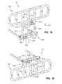
- FIG. 5is a perspective view of the siderail assembly of FIG. 2 ;
- FIG. 6is a perspective view of the siderail assembly similar to FIG. 5 showing the siderail assembly in a blocking postion;
- FIG. 7is a perspective view of the siderail assembly similar to FIG. 5 showing the siderail assembly in the egress position;
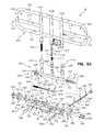
- FIG. 8is an exploded perspective view of the siderail assembly of FIG. 5 ;
- FIG. 9is an exploded view of an illustrative embodiment latch assembly of the siderail assembly of FIG. 5 ;
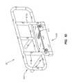
- FIG. 10is a perspective view of a further illustrative embodiment siderail assembly in a first raised position according to the present disclosure
- FIG. 11is a perspective view of the siderail assembly of FIG. 10 in a second raised position
- FIG. 12is a perspective view of the siderail assembly of FIG. 10 in a lowered position
- FIG. 13is a perspective view, with a partial cut-away, of the siderail assembly of FIG. 10 ;
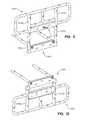
- FIG. 14is a perspective view of a further illustrative embodiment siderail assembly in a first raised position according to the present disclosure
- FIG. 15is a perspective view of the siderail assembly of FIG. 14 in a second raised position
- FIG. 16is a perspective view of the siderail assembly of FIG. 14 in a lowered position
- FIG. 17is a perspective view, with a partial cut-away, of the siderail assembly of FIG. 14 ;
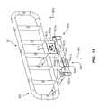
- FIG. 18is a perspective view of a further illustrative embodiment siderail assembly in a first raised position
- FIG. 19is a perspective view of a further illustrative embodiment siderail assembly in a first raised position
- FIG. 20is a perspective view of the siderail assembly of FIG. 19 in a second raised position.
- FIG. 21is a perspective view of the siderail assembly of FIG. 19 in a lowered position.
- a patient support 10is illustrated as including a base frame 12 supported by a plurality of casters 14 .
- An intermediate frame 16is supported by the base frame 12 and is coupled to an articulating support deck 18 .
- the support deck 18is of conventional design and illustratively includes a plurality of sections configured to articulate relative to one another, including a head section 20 pivotally coupled to a seat section 22 , and a foot section 24 pivotally coupled to the seat section 22 .
- a thigh section 26is pivotally coupled intermediate the seat section 22 and the foot section 24 .
- the seat section 22may be rigidly mounted to the intermediate frame 16 to prevent movement therebetween.
- the support deck 18includes sliding panels 27 and siderail sliding panels 29 which may be moved laterally to expand and retract the width of the deck 18 .
- Examples of expanding support decksare provided in U.S. Patent Application entitled “BARIATRIC BED”, filed Jul. 28, 2004 (60/591838) and U.S. Pat. Nos. 6,212,714 and 6,357,065, the disclosures of which are expressly incorporated by reference herein.
- a headboard 28is mounted to the intermediate frame 16 adjacent a head end 30 of patient support 10
- a footboard 32is mounted to the intermediate frame 16 adjacent a foot end 34 of patient support 10
- the patient support 10further includes a pair of head end siderail assemblies 36 and a pair of foot end siderail assemblies 38 coupled to the support deck 18 through the associated siderail sliding panels 29 on opposite sides of the patient support 10 .
- Head end and foot end siderail assemblies 36 , 38are configured to move between a first deck position, as shown in FIG. 2 , and a second deck position, as shown in FIG. 4 to permit the siderail assemblies 36 , 38 to move with siderail sliding panels 29 . Additionally, head end and foot end siderail assemblies 36 , 38 are configured to move between first raised or blocking position, as shown in FIG. 6 , a second raised or intermediate position, as shown in FIG. 5 , and a lowered or egress positions, as shown in FIG. 7 , to permit entry and egress of patients into and out of patient support 10 .
- the siderail assembliesinclude structural components, described herein, selected to support the stated patient weights.
- the blocking positionis intended to prevent a patient (not shown) from exiting from patient support 10 .
- the intermediate positionallows a caregiver (not shown) access to the patient while still maintaining some hindrance to patient egress.
- the egress positionallows a caregiver additional access to the patient and for movement of the patient from patient support 10 .
- the blocking, intermediate, and egress positions of the siderail assemblies 36 , 38allow for reducing the likelihood of patient egress and allowing a low bed exit position (not shown).
- Each of the blocking, intermediate, and egress positionsmay be secured in position with a latching mechanism to be described herein.
- head end siderail assembly 36includes a head end upper siderail assembly 400 and a lower siderail assembly 404 .
- Foot end siderail assembly 38includes a foot end upper siderail assembly 402 and lower siderail assembly 404 .
- Upper siderail assemblies 400 , 402cooperate with lower siderail assemblies 404 to permit upper siderail assemblies 400 , 402 to move between the blocking, intermediate and egress positions.
- Upper siderail assemblies 400 , 402include respective upper members 406 , 408 , respective lower members 410 , 412 , curved grip members 414 , lower assembly receiving members 416 a - c , stoppers 415 , and upper release assemblies 417 .
- Head end upper siderail assembly 400further includes a pair of blocking members 418 .
- Blocking members 418cooperate with upper member 406 to define a pair of openings 420 both sized to receive a removable controller (not shown). Examples of the removable controller are provided in U.S. Pat. No. 6,691,346, the disclosure of which is expressly incorporated by reference herein.
- foot end upper siderail assembly 402includes a blocking member 422 .
- Head end siderail assembly 36 and foot end siderail 38are similar and description of operation and components of head end siderail assembly 36 is interchangeable with foot end siderail 38 . The differences between assemblies 36 , 38 are mostly cosmetic and not functional.
- lower assembly 404includes lower assembly interactive members 422 a - c configured to be received by respective receiving members 416 a - c , a rotation member 424 including a first end 426 and a second end 428 , a biasing spring 430 configured to bias upper siderail assemblies 400 , 402 upwards, a release assembly 431 , and a rotation stop 432 .
- siderail sliding panel 29includes a main body 433 , a rotation assembly 434 coupled to main body 433 , width adjustment members 438 a - b , a width adjustment assembly 436 configured to cooperate with adjustment member 438 a to adjust the width of support deck 18 , a restraint strap connector 442 , and a siderail stop 444 .
- Siderail stopincludes a base 443 and a cap 445 .
- Interactive members 422 a - care cylindrical tubes sized to be received by respective receiving members 416 a - c .
- Interactive member 422 aincludes a channel 435 configured to receive stopper 415 .
- stopper 415is a screw and a washer threaded into Interactive member 422 a .
- Stopper 415prevents removal of upper siderail assemblies 400 , 402 from lower siderail assemblies 404 .
- Interactive member 422 csupports biasing spring 430 which is received inside receiving member 416 c to bias upper siderail assembly 400 towards the blocking position.
- Each interactive members 422 a - bincludes an upper latch opening 446 and a lower latch opening 448 . Additionally, interactive member 422 b receives rotation stop 432 and is received by receiving member 416 b.
- Release assembly 431includes a release shaft 450 , a release shaft tube 452 , a release shaft spring 454 , and a washer 456 .
- Rotation assembly 434includes a knob 458 , a screw 460 , an end cap 462 , a locking hub disk 464 , and a locking hub shaft 466 .
- Locking hub disk 464 and locking hub shaft 466cooperate to form a locking hub assembly 468 .
- Release shaft 450includes body 469 having a first end 470 and a second end 472 , an opening 474 , a stopper end 476 , and a rotation stopper groove or channel 478 .
- Main body 433includes a pivot end 480 and a rotation end 482 .
- Pivot end 480includes a pivot end plate 484 , a pair of screws 485 , a pair of washers 486 , a pivot bar 488 , and a mounting plate 490 .
- Mounting plate 490includes a pair of threaded holes 492 .
- Pivot end plate 484includes a pair of screw holes 494 and bar hole 496 . Screws 485 go through holes 494 and thread into threaded holes 492 .
- Pivot bar 488is welded to bar hole 496 .
- Rotation end 482includes a threaded hole 498 , a hub shaft opening 500 , and a release shaft opening 502 .
- Screw 460fits in an opening 504 in end cap 462 and threads into threaded hole 498 holding end cap 462 in place.
- Hub shaft opening 500receives and hold locking hub assembly 468 .
- Second end 428includes a pair of set screws 505 and a body 506 having a pair of set screw openings 508 , a shaft opening 510 , and hub shaft opening 500 .
- First end 426includes a washer 512 and a pair of wave washers 514 .
- Washer 512provides a bearing surface for wave washers 514 .
- Wave washers 514provide resistance so upper rail assembly 400 does not abruptly swing down.
- Set screws 505thread through set screw openings 508 to hold release shaft tube 452 in place.
- Rotation stop 432includes a spring 516 and a body 518 including a release shaft opening 520 .
- Release shaft opening 520is sized to receive stopper end 476 and positioned over rotation stopper channel 478 .
- release shaft opening 520is biased upwards into contact with rotation stopper channel 478 preventing rotation assembly 434 from allowing siderail assemblies 400 , 402 to rotate.
- release shaft opening 520is positioned to allow stopper end 476 to move through opening 520 allowing rotation of siderail assemblies 400 , 402 .
- upper release assembly 417includes a bracket 522 , a handle 523 , a shaft 524 , a spring 526 , a pair of release members 528 , a pair of holding members 532 , and a snap ring 534 .
- Shaft 524includes a body 535 , a pair of holding member apertures or channels 536 , and a snap ring channel 538 .
- Handle 523includes a lift portion 540 and a rotation portion 542 including an opening 544 sized to receive shaft 524 .
- Each release member 528includes a body 546 , a locking portion 548 , and a holding member opening 550 .
- Bracket 522includes a first wing 552 , a second wing 554 , and bolt openings 556 .
- First wing 552includes a first wing opening 558 sized to receive shaft 524 .
- Second wing 554includes a second wing opening 560 including a stopper tab 562 .
- bracket 522bolts to a mounting plate 564 (shown in FIG. 1 ).
- Handle 523is placed between first wing 552 and second wing 554 , spring 526 is placed between release members 528 .
- Holding members 532are placed through holding member channels 536 into holding member openings 550 and into a pair of channels (not shown) in handle 523 .
- snap ring 534is place in snap ring channel 538 outside first wing 552 holding the entire assembly in place.
- width adjustment assembly 436is configured to cooperate with adjustment member 438 a to adjust the width of support deck 18 .
- Width adjustment assembly 436includes an extension bar 563 , a knob 566 , a first spring clip 568 , and a second spring clip 569 .
- Adjustment member 438 aincludes a standard deck width hole 570 , a extended deck width hole 572 , and an assembly receiving opening 573 .
- Spring clips 568 , 569each include a locking portion 574 and a biasing portion 576 .
- Adjustment assembly 436is configured to slide into receiving opening 573 .
- Spring clip 569prevents removal of adjustment assembly 436 from adjustment member 438 a during operation. While in the first deck position, shown in FIG. 2 , locking portion 574 of button 568 is biased into standard width hole 570 . While in the second deck position, shown in FIG. 4 , locking portion 574 of button 569 is biased into extended deck width hole 572 .
- FIGS. 2-4siderail assembly 36 moves between the intermediate position ( FIG. 2 ) with a portion 575 of upper siderail assembly 400 above the upper surface of a mattress 576 and the egress position ( FIG. 3 ) with the upper siderail assembly 400 below the surface of the mattress 576 .
- Mattress 576includes a main body 578 and an extension body or bolster 586 .
- Siderail assembly 36is in the second deck position to accommodate the addition of extension body 586 . Additional disclosure of the mattress structures may be found in U.S. Utility Application entitled “Hospital Bed” (60/659368) which is expressly incorporated by reference herein.
- each of siderail assemblies 36 , 38will be positioned below or substantially below at least one of base frame 12 , intermediate frame 16 , and/or deck 18 when in the egress position.
- knob 566In operation of width adjustment of deck 18 , siderail sliding panels 29 must be extended.
- the caregiverpushes knob 566 inwards towards frame 12 .
- Knob 566is coupled to extension bar 563 .
- Extension bar 563includes a spring clip receiver 582 .
- Spring clip receiver 582is configured to push spring clip 568 .
- Spring clip receiver 582depresses locking portion 574 of first spring clip 568 and allows slide assembly 29 to be pulled until locking portion 574 of second snap button 569 engages the end of the socket (not shown).
- Locking portion 574 of spring button 568is then locked in the socket hole and second snap button 569 is locked at the end of the socket preventing movement of slide assembly 29 from moving in either direction.
- Spring clip receiver 582is a channel of sufficient length to allow locking portion 574 to remain in extended deck width hole 572 and allow knob 566 to return to its initial position. In alternative embodiments, there could be multiple width positions requiring additional deck width holes.
- the caregiverIn operation to move between the intermediate position ( FIG. 5 ) and the blocking position ( FIG. 6 ), the caregiver uses upper release assembly 417 .
- the caregiverlifts handle 523 .
- Holding members 532move along holding member channels 536 and the pair of holding channels in handle 523 causing movement of release members 528 inwards. This movement moves release members 528 out of contact with lower latch openings 448 .
- the caregiverbegins lifting upper siderail assembly 400 and releases handle 523 . This allows the caregiver to raise the upper siderail assembly 400 until release members 528 snap into upper latch opening 446 locking upper siderail assembly 400 into blocking position.
- Stopper 415is positioned in channel 433 . This prevents a caregiver from accidentally removing the upper siderail assembly 400 from lower siderail assembly 404 without removing stopper 415 .
- release shaft opening 520is biased upwards into contact with rotation stopper channel 478 preventing rotation assembly 434 from allowing siderail assemblies 400 , 402 to rotate.
- release shaft opening 520is positioned to allow stopper end 476 to move through opening 520 allowing rotation of siderail assemblies 400 , 402 . This allows rotation of siderail assemblies 400 , 402 only when the siderail is in the intermediate position. In alternative embodiments, rotation stop 423 could be removed allowing rotation in all positions.
- the caregiveruses rotation assembly 434 .
- the caregiverpulls knob 458 in a direction 461 away from lower assembly 404 .
- Pulling knob 458 in direction 461moves locking hub disk 464 in the same direction as knob 458 .
- the caregiverreleases knob 458 and spring 454 biases knob 458 to its original position.
- Siderail assembly 36is not locked in the egress position and movement of siderail assembly 36 is enabled without additional movement of knob 458 .
- shaft 466slides into hub shaft opening 500 .
- an addition hub shaft opening 500is positioned opposition hub shaft opening to lock siderail assembly 36 in the egress position.
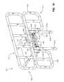
- FIGS. 10-13Another illustrative embodiment siderail assembly 36 ′ is shown in FIGS. 10-13 .
- Siderail assembly 36 ′includes an upper siderail assembly 602 and lower siderail assembly 604 .
- Upper siderail assembly 602cooperates with lower siderail assembly 604 to permit upper siderail assembly 602 to move between the blocking position ( FIG. 11 ), the intermediate position ( FIG. 10 ), and the egress position ( FIG. 12 ).
- Upper siderail assembly 602includes, lower assembly receiving members 616 a , 616 b and an upper release assembly 617 .
- Lower assembly 604includes lower assembly interactive members 622 a , 622 b configured to be received by respective receiving members 616 a , 616 b.
- upper release assembly 617includes a bracket 722 , a handle 723 , a shaft (not shown), a pair of release members 728 a , 728 b , a pair of first links 732 a , 732 b , a main link 734 , and a pair of outer brackets 735 a , 735 b .
- Bracket 722includes a back member 736 , a front member 738 , and retaining members 740 .
- Handle 723couples to the shaft (not shown).
- the shaft (not shown)is positioned through front member 738 and is welded to main link 734 . In alternative embodiments the shaft maybe press fit in an opening (not shown) in main link 734 .
- Outer brackets 735 a, bcontain openings 742 configured to receive respective release members 728 a , 728 b .
- Main link 734includes a pair of coupling members 744 .
- Release members 728 a, binclude first link coupling members 750 .
- First links 732 aeach include a main bracket receiver 746 and a release member receiver 748 .
- Main bracket receivers 746receive coupling members 744 and release member receivers 748 receive first link coupling members 750 .
- Release members 728 a, bare configured to move between a locked position interacting with an intermediate position opening (not shown) and a locked position interacting with a blocking position opening (not shown). Both intermediate position opening (not shown) and blocking position opening (not shown) located through a first wall (not shown) in both lower assembly interactive members 622 a , 622 b and receiving members 616 a , 616 b.
- the caregiverrotates handle 723 in either a first direction 752 or second direction 754 .
- Rotation of handle 723 in either first or second directions 752 , 754moves release members 728 a , 728 b in an inward direction 756 out of contact with both lower assembly interactive members 622 a , 622 b and receiving members 616 a , 616 b .
- Handle 723is biased to the starting position.
- release members 728 a , 728 bmove in the outward position 758 into contact with both lower assembly interactive members 622 a , 622 b and receiving members 616 a , 616 b .
- While in contact with both lower assembly interactive members 622 a , 622 b and receiving members 616 a , 616 bupper siderail assembly 602 is locked in either the intermediate position or the blocking position.
- FIGS. 14-17Another illustrative embodiment siderail assembly 36 ′′ is shown in FIGS. 14-17 .
- Siderail assembly 36 ′′includes an upper siderail assembly 802 and lower siderail assembly 804 .
- Upper siderail assembly 802cooperates with lower siderail assembly 804 to permit upper siderail assembly 802 to move between the blocking position ( FIG. 15 ), the intermediate position ( FIG. 14 ), and the egress position ( FIG. 16 ).
- Upper siderail assembly 802includes, lower assembly receiving members 816 a - c and an upper release assembly 817 .
- Lower assembly 804includes a rotation assembly 806 and lower assembly interactive members 822 a - c configured to be received by respective receiving members 816 a - c.
- Rotation assembly 806includes a handle 808 , bracket 809 , a pair of springs (not shown), and a pair of release members 810 configured to cooperate with a pair of openings (not shown) in lower siderail assembly 804 .
- Release members 810are biased into the pair of openings by the pair of springs (not shown).
- an additional pair of openingsis provided to interact with release members 810 to lock siderail assembly 36 ′′ in the egress position.
- upper release assembly 817includes a bracket 822 , a handle 823 , a shaft (not shown), a pair of release members 828 a , 828 b , a pair of first links 832 a , 832 b , and a main link (not shown).
- Handle 823couples to a shaft 836 through the main link (not shown).
- Shaft 836is positioned through first openings 837 .
- First links 832 a , 832 bcontain openings 842 configured to receive respective release members 828 a , 828 b .
- first links 832 a , 832 bare configured to pivot around respective pivot shafts 841 a , 841 b .
- Release members 828 a , 828 binclude first link coupling members 850 .
- Release members 828 a , 828 bare configured to move between a locked position interacting with an intermediate position opening (not shown) and a locked position interacting with a blocking position opening (not shown). Both intermediate position opening and blocking position opening located through a first wall (not shown) of both lower assembly interactive members 822 a , 822 b and receiving members 816 a , 816 b.
- the caregiverIn operation to move between the intermediate position ( FIG. 14 ) and the blocking position ( FIG. 15 ), the caregiver lifts handle 823 in an upward direction 852 .
- Lifting handle 823 in upward direction 852moves release members 828 a , 828 b in an inward direction 856 out of contact with both interactive members 822 a , 822 b and receiving members 816 a , 816 b .
- Handle 823is biased to the starting position.
- the caregiverstarts lifting upper assembly 802 .
- the caregiverreleases handle 823 release members 828 a , 828 b move in the outward position 858 into contact with both lower assembly interactive members 822 a , 822 b and receiving members 816 a , 816 b .
- While in contact with both lower assembly interactive members 822 a , 822 b and receiving members 816 a , 816 bupper siderail assembly 802 is locked in either the intermediate position or the blocking position.
- the caregiveruses rotation assembly 806 .
- the caregiverpulls handle 808 downwards in a direction 807 .
- Pulling handle 808moves release members 810 out of contact the pair of openings in lower siderail assembly 804 allowing rotation of siderail assembly 36 ′′.
- the caregiverreleases handle 808 and the pair of springs bias handle 808 towards its original position.
- Siderail assembly 36 ′′is not locked in the egress position and rotation upwards of siderail assembly 36 ′′ is enabled without additional movement of handle 808 .
- release members 810slide into the pair of openings in lower siderail assembly 804 .
- FIG. 18Another illustrative embodiment siderail assembly 36 ′′′ is shown in FIG. 18 .
- Siderail assembly 36 ′′′uses all the same components as siderail assembly 36 ′′ except it uses upper release assembly 417 from siderail assembly 36 .
- Upper release assembly 417 of siderail assembly 36 ′′′includes all components and operates as does upper release assembly 417 of siderail assembly 36 .
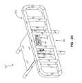
- FIGS. 19-21Yet another illustrative embodiment siderail assembly 36 ′′′′ is shown in FIGS. 19-21 .
- Siderail assembly 36 ′′′′includes an upper siderail assembly 902 and lower siderail assembly 904 .
- Upper siderail assembly 902cooperates with lower siderail assembly 904 to permit upper siderail assembly 902 to move between the blocking position ( FIG. 21 ), the intermediate position ( FIG. 19 ), and rotate to the egress position ( FIG. 20 ).
- siderail assembly 36 ′′′′is below deck 18 of patient support 10 .
- Upper siderail assembly 902includes, lower assembly receiving members 916 a , 916 b , upper blocker 911 , lower blocker 913 , and an upper release assembly 917 .
- Lower blockerincludes a first blocker member 918 , and a second blocker member 920 .
- Lower assembly 904includes a height adjustment assembly 906 lower assembly interactive members 922 a , 922 b configured to be received by respective receiving members 916 a , 916 b .
- To rotate upper blocker 911pull up on upper release assembly 917 .
- a tube(not shown) is welded to upper blocker 911 .
- second blocker member 920runs through the tube and has a hole (not shown) to engage with 917 .
- Height adjustment assembly 906includes a handle 908 , bracket 909 , a pair of release links 910 , and a pair of release members (not shown) configured to cooperate with a pair of openings 928 in lower siderail assembly 904 .
- Receiving member 916 aincludes an opening (not shown). This allows release members to interact with one of openings 928 and the opening in receiving member 916 a .
- Release links 910are coupled to handle 908 by a pair of link couplers 930 and release links 910 pivot about pivot pins 932 . Release assembly 906 is biased in the rest position with release members locked in one of openings 928 in lower siderail assembly 904 .
- the caregiveruses height adjustment assembly 906 .
- the caregiverlifts handle 908 upwards.
- Lifting handle 908rotates release links 910 about pivot pins 932 .
- the movement of release links 910moves release members out of contact the opening in receiving member 916 a and opening 928 .
- the caregiverreleases handle 908 and handle 908 is biased towards its original position.
- siderail assembly 36 ′′′′is not locked in the egress position and movement upwards of siderail assembly 36 ′′′′ is enabled without additional movement of handle 908 .
- release memberslock into opening 928 in lower siderail assembly 904 .
Landscapes
- Health & Medical Sciences (AREA)
- Nursing (AREA)
- Life Sciences & Earth Sciences (AREA)
- Animal Behavior & Ethology (AREA)
- General Health & Medical Sciences (AREA)
- Public Health (AREA)
- Veterinary Medicine (AREA)
- Invalid Beds And Related Equipment (AREA)
Abstract
Description
Claims (20)
Priority Applications (1)
| Application Number | Priority Date | Filing Date | Title |
|---|---|---|---|
| US11/368,791US7805782B2 (en) | 2005-03-07 | 2006-03-06 | Siderail for a hospital bed |
Applications Claiming Priority (2)
| Application Number | Priority Date | Filing Date | Title |
|---|---|---|---|
| US65922105P | 2005-03-07 | 2005-03-07 | |
| US11/368,791US7805782B2 (en) | 2005-03-07 | 2006-03-06 | Siderail for a hospital bed |
Publications (2)
| Publication Number | Publication Date |
|---|---|
| US20060195984A1 US20060195984A1 (en) | 2006-09-07 |
| US7805782B2true US7805782B2 (en) | 2010-10-05 |
Family
ID=36955306
Family Applications (1)
| Application Number | Title | Priority Date | Filing Date |
|---|---|---|---|
| US11/368,791Active2027-10-01US7805782B2 (en) | 2005-03-07 | 2006-03-06 | Siderail for a hospital bed |
Country Status (2)
| Country | Link |
|---|---|
| US (1) | US7805782B2 (en) |
| CA (1) | CA2505083A1 (en) |
Cited By (39)
| Publication number | Priority date | Publication date | Assignee | Title |
|---|---|---|---|---|
| US20080092294A1 (en)* | 2006-09-14 | 2008-04-24 | Rawls-Meehan Martin B | Methods and systems of an adjustable bed |
| US20090188042A1 (en)* | 2008-01-21 | 2009-07-30 | Stryker Corporation | Hospital bed |
| US8069512B2 (en)* | 2006-09-14 | 2011-12-06 | Martin B Rawls-Meehan | Adjustable bed frame |
| US20120102643A1 (en)* | 2010-11-03 | 2012-05-03 | Turner Jonathan D | Siderail assembly for patient support apparatus |
| US20120153098A1 (en)* | 2010-12-20 | 2012-06-21 | Jeffrey Riach | Portable Table Support |
| US8239986B2 (en) | 2008-03-13 | 2012-08-14 | Hill-Rom Services, Inc. | Siderail assembly for a patient-support apparatus |
| US8474076B2 (en) | 2011-02-04 | 2013-07-02 | Hill-Rom Services, Inc. | Adjustable foot section for a patient support apparatus |
| US8909378B2 (en) | 2006-09-14 | 2014-12-09 | Martin B Rawls-Meehan | Adjustable bed position control |
| US8909357B2 (en) | 2007-09-14 | 2014-12-09 | Martin B Rawls-Meehan | System for tandem bed communication |
| US8926535B2 (en) | 2006-09-14 | 2015-01-06 | Martin B. Rawls-Meehan | Adjustable bed position control |
| US9044366B2 (en) | 2006-09-14 | 2015-06-02 | Ascion, Llc | Adjustable mattress support facility |
| USD733452S1 (en) | 2010-02-09 | 2015-07-07 | Ascion, Llc | Adjustable bed |
| USD736023S1 (en) | 2013-01-25 | 2015-08-11 | Ascion, Llc | Adjustable bed |
| US9173793B2 (en) | 2006-09-14 | 2015-11-03 | Ascion, Llc | Adjustable bed frame with mattress retaining brackets |
| US9205009B2 (en) | 2012-12-17 | 2015-12-08 | Hill-Rom Services, Inc. | Patient support apparatus having movable handles |
| US9248064B2 (en) | 2013-03-15 | 2016-02-02 | Hillenbrand Management Company Llc | Sheet receiver for patient repositioning system |
| WO2016022564A1 (en)* | 2014-08-04 | 2016-02-11 | Hillenbrand Management Company Llc | Patient repositioning system for bariatric bed |
| US9333139B2 (en) | 2009-05-05 | 2016-05-10 | Hillenbrand Management Company Llc | Patient positioning device |
| US9381125B2 (en) | 2012-03-02 | 2016-07-05 | Stryker Corporation | Patient support |
| US9433546B2 (en) | 2006-09-14 | 2016-09-06 | Ascion, Llc | Dual motion deck-on-deck bed frame |
| US20170055717A1 (en)* | 2015-08-26 | 2017-03-02 | Hill-Rom Services, Inc. | Bed with a Stowable Siderail |
| US9603764B2 (en) | 2014-02-11 | 2017-03-28 | Medline Industries, Inc. | Method and apparatus for a locking caster |
| US9622927B1 (en)* | 2012-10-05 | 2017-04-18 | Gf Health Products, Inc. | Bed with extendable and retractable extensions |
| US9629473B2 (en) | 2009-02-09 | 2017-04-25 | Ascion, Llc | Leg assembly |
| US10130536B2 (en) | 2013-09-06 | 2018-11-20 | Stryker Corporation | Patient support usable with bariatric patients |
| US10137045B2 (en) | 2013-03-15 | 2018-11-27 | Hillenbrand Management Company Llc | Patient repositioning system |
| US10154930B2 (en) | 2016-08-01 | 2018-12-18 | Stryker Corporation | EMS backboard |
| US10188569B2 (en) | 2013-09-06 | 2019-01-29 | Stryker Corporation | Patient support usable with bariatric patients |
| US10426680B2 (en) | 2015-07-31 | 2019-10-01 | Hill-Rom Services, Inc. | Air bladder control of mattress/frame width expansion |
| CN110974574A (en)* | 2015-10-14 | 2020-04-10 | Qfix系统有限责任公司 | Patient cot and method of transferring a patient from a cot to a target physical therapy device |
| EP3632390A3 (en)* | 2018-10-01 | 2020-07-15 | Hill-Rom Services, Inc. | Method and apparatus for upgrading a bed to include moveable components |
| US10842701B2 (en) | 2016-10-14 | 2020-11-24 | Stryker Corporation | Patient support apparatus with stabilization |
| US10849804B2 (en) | 2015-09-24 | 2020-12-01 | Umano Medical Inc. | Hospital bed with adjustable width |
| US11052005B2 (en) | 2017-09-19 | 2021-07-06 | Stryker Corporation | Patient support apparatus with handles for patient ambulation |
| US11116680B2 (en) | 2017-09-19 | 2021-09-14 | Stryker Corporation | Patient support apparatus for controlling patient ingress and egress |
| US11160705B2 (en) | 2017-10-20 | 2021-11-02 | Stryker Corporation | Adjustable patient support apparatus for assisted egress and ingress |
| US11259975B2 (en)* | 2018-10-13 | 2022-03-01 | Breanne O'Leary | Apparatus providing extension of a surgical table width allowing adaptation to the parameters of the specific patient |
| US12036161B2 (en) | 2019-08-16 | 2024-07-16 | Stryker Corporation | Patient support with deck width monitoring and control |
| WO2025101736A1 (en)* | 2023-11-07 | 2025-05-15 | Sizewise Rentals, L.L.C. | Expansion control assembly |
Families Citing this family (30)
| Publication number | Priority date | Publication date | Assignee | Title |
|---|---|---|---|---|
| AU2003299869A1 (en)* | 2002-12-26 | 2004-07-29 | Gendron, Inc. | Bariatric patient management system |
| EP1621174B1 (en)* | 2004-07-30 | 2011-10-19 | Hill-Rom Services, Inc. | Patient support having powered adjustable width |
| CA2523168C (en)* | 2004-10-18 | 2014-02-18 | Stryker Corporation | Bed siderail |
| US7712166B2 (en)* | 2004-12-03 | 2010-05-11 | Stryker Corporation | Bed siderail and support structure |
| US7788748B2 (en)* | 2005-04-06 | 2010-09-07 | Piedmont Global Solutions, Inc. | Hospital beds with a rotating sleep surface that can translate into a chair configuration |
| GB0513227D0 (en)* | 2005-06-29 | 2005-08-03 | Ferno Uk Ltd | Stretcher |
| US8864205B2 (en) | 2006-06-28 | 2014-10-21 | Stryker Corporation | Patient support with wireless data and/or energy transfer |
| EP2046259B1 (en)* | 2006-06-28 | 2014-07-02 | Stryker Corporation | Patient support |
| NL2000533C2 (en)* | 2007-03-13 | 2008-09-16 | Schell Ind | Bed with compact folding side guard. |
| US7712171B2 (en) | 2007-04-25 | 2010-05-11 | Hill-Rom Services, Inc. | Patient support including turn assist, low air loss, or integrated lateral transfer |
| WO2009152429A1 (en) | 2008-06-13 | 2009-12-17 | Hill-Rom Services, Inc. | Item support apparatuses and systems for bedside |
| US20110010854A1 (en) | 2009-07-15 | 2011-01-20 | Zerhusen Robert M | Siderail with storage area |
| FR2955251B1 (en)* | 2010-01-18 | 2013-06-28 | Hill Rom Sas | MEDICALIZED BED EQUIPPED WITH A DEVICE FOR AIDING THE MOBILITY OF A PATIENT. |
| CN201612383U (en)* | 2009-12-23 | 2010-10-27 | 厦门纬嘉运动器材有限公司 | Bed widening mechanism of obese people bed |
| US8484778B2 (en) | 2010-09-07 | 2013-07-16 | Hill-Rom Services, Inc. | Side rail with two position storage feature |
| US20120144583A1 (en)* | 2010-12-08 | 2012-06-14 | Turner Jonathan D | Siderail movable to separate chair egress position |
| FR2979818B1 (en) | 2011-09-08 | 2017-01-06 | Medicatlantic Sa | BED BARRIER, IN PARTICULAR A MEDICAL BED, AND METHOD OF MOUNTING SUCH A BARRIER |
| WO2013058753A1 (en)* | 2011-10-20 | 2013-04-25 | Ferno-Washington, Inc. | Work surface extensions for embalming tables and embalming tables including the same |
| FR2985904B1 (en) | 2012-01-20 | 2014-12-19 | Medicatlantic Sa | BED COMPRISING A RETRACTABLE BARRIER HAVING A TECHNICAL HELPING POINT FOR BEARING |
| ES2900556T3 (en)* | 2012-07-25 | 2022-03-17 | Joerns Healthcare Llc | Adjustable width mattress |
| US9173796B2 (en)* | 2013-02-05 | 2015-11-03 | Hill-Rom Services, Inc. | Bed with a powered width expansion wing with manual release |
| JP5922608B2 (en)* | 2013-03-22 | 2016-05-24 | ジーイー・メディカル・システムズ・グローバル・テクノロジー・カンパニー・エルエルシー | Medical device table and medical device |
| KR101476267B1 (en)* | 2013-04-08 | 2014-12-24 | 주식회사 해피베드 | Safety rail for patients |
| WO2017015602A1 (en) | 2015-07-23 | 2017-01-26 | Stryker Corporation | Patient support apparatus with side rail |
| US11737934B2 (en) | 2015-10-14 | 2023-08-29 | Qfix Systems, Llc | MRI compatible patient trolley |
| CN107772902B (en)* | 2016-08-31 | 2018-11-20 | 麒盛科技股份有限公司 | A kind of beddo applied to the waist ejecting mechanism of beddo and including the waist ejecting mechanism |
| GB2559104B (en)* | 2016-10-25 | 2020-04-22 | Benmor Medical Uk Ltd | Barrier for a bed |
| US20180177654A1 (en)* | 2016-12-22 | 2018-06-28 | Stephen Muscarello | Hospital bed or gurney having selective patient privacy |
| CA3081153A1 (en)* | 2017-11-01 | 2019-05-09 | Umano Medical Inc. | Shock absorbing assembly for a patient support apparatus |
| USD983585S1 (en)* | 2021-11-10 | 2023-04-18 | Arjo Ip Holding Ab | Grab handle for hospital bed |
Citations (39)
| Publication number | Priority date | Publication date | Assignee | Title |
|---|---|---|---|---|
| US4641385A (en)* | 1985-07-29 | 1987-02-10 | Simmons Universal Corporation | Armboard rail |
| US5038430A (en)* | 1990-03-22 | 1991-08-13 | Invacare Corporation | Attaching means for bed cross brace |
| US5083332A (en)* | 1989-07-28 | 1992-01-28 | Hill-Rom Company, Inc. | Hospital bed with collapsible side edges and laterally-movable side guards |
| US5083334A (en) | 1990-10-12 | 1992-01-28 | Ssi Medical Services, Inc. | Side guard for patient support |
| US5129117A (en) | 1990-11-28 | 1992-07-14 | Hill-Rom Company, Inc. | Birth assist protection guard |
| US5179744A (en)* | 1989-07-28 | 1993-01-19 | Hill-Rom Company, Inc. | Hospital bed with inflatable and collapsible side edges and laterally-movable side guards |
| US5191663A (en) | 1992-07-02 | 1993-03-09 | Hill-Rom Company, Inc. | Hospital bed sideguard pads |
| US5345629A (en) | 1988-03-23 | 1994-09-13 | American Life Support Technology | Patient support system |
| US5394580A (en) | 1993-06-11 | 1995-03-07 | Hill-Rom Company, Inc. | Hospital bed with three position patient side guards |
| US5732423A (en) | 1995-08-04 | 1998-03-31 | Hill-Rom, Inc. | Bed side rails |
| US5802636A (en) | 1996-11-12 | 1998-09-08 | Hill-Rom, Inc. | Integrated siderail and accessory rail for a bed |
| US5832549A (en) | 1995-12-18 | 1998-11-10 | Le Couviour Mobilier Specialise Sante | Bed side part |
| US5878452A (en) | 1996-12-03 | 1999-03-09 | Hill-Rom, Inc. | Long term care bed controls |
| US5987666A (en)* | 1999-03-15 | 1999-11-23 | St. Luke Foundation | Gap-filling pad disposable between a mattress and a bed rail |
| US6021533A (en) | 1997-08-25 | 2000-02-08 | Hill-Rom, Inc. | Mattress apparatus having a siderail down sensor |
| US6212714B1 (en) | 1995-01-03 | 2001-04-10 | Hill-Rom, Inc. | Hospital bed and mattress having a retracting foot section |
| US6240580B1 (en) | 1999-03-08 | 2001-06-05 | Hill-Rom, Inc. | Extruded side rail apparatus |
| US6240583B1 (en) | 1996-12-03 | 2001-06-05 | Hill-Rom, Inc. | Ambulatory assist arm for a bed |
| US6357065B1 (en) | 1999-11-15 | 2002-03-19 | Mellen Air Manufacturing, Inc. | Variable width bariatric modularbed |
| US6363552B1 (en) | 2000-03-17 | 2002-04-02 | Hill-Rom Services, Inc. | Bed siderail |
| US6374437B1 (en)* | 1997-06-24 | 2002-04-23 | Voelker Moebelproduktionsgesellschaft Mbh | Bed, specially a medical or care bed |
| US6401277B1 (en) | 1999-03-12 | 2002-06-11 | Hill-Rom Services, Inc. | Siderail extender |
| US6427264B1 (en) | 1999-03-19 | 2002-08-06 | Hill-Rom Services, Inc. | Gap filler for bed |
| US20030019035A1 (en)* | 1999-01-22 | 2003-01-30 | Heimbrock Richard H. | Convertible stretcher |
| US6622323B2 (en) | 2000-03-24 | 2003-09-23 | Hill-Rom Services, Inc. | Bed siderails having flexible portions |
| US20030177578A1 (en)* | 2000-09-28 | 2003-09-25 | Jack Nixon | Side frame for a cot or bed |
| US6691346B2 (en) | 1999-12-29 | 2004-02-17 | Hill-Rom Services, Inc. | Foot controls for a bed |
| US6725474B2 (en) | 1990-05-16 | 2004-04-27 | Hill-Rom Services, Inc. | Hospital bed |
| US6728985B2 (en) | 2001-08-15 | 2004-05-04 | Hill-Rom Services, Inc. | Ambulatory assist arm apparatus |
| US20040123387A1 (en)* | 2002-12-13 | 2004-07-01 | Marsden Andrew W. | Bed rail with clamping force indicator |
| US6779209B2 (en) | 2000-12-29 | 2004-08-24 | Hill-Rom Services, Inc. | Bed siderail apparatus |
| US6820293B2 (en) | 2002-09-26 | 2004-11-23 | Hill-Rom Services, Inc. | Bed siderail pad apparatus |
| US6862759B2 (en) | 1998-06-26 | 2005-03-08 | Hill-Rom Services, Inc. | Hospital bed |
| US6874179B2 (en) | 2000-10-19 | 2005-04-05 | Hill-Rom S.A.S. | Bed with articulated barrier elements |
| US7260860B2 (en) | 2004-08-04 | 2007-08-28 | Hill-Rom Services, Inc. | Mattress system for a hospital bed |
| US20080127415A1 (en)* | 2004-03-12 | 2008-06-05 | Ruschke Jeffrey A | Variable Height Siderail for a Bed |
| US7406729B2 (en)* | 2004-07-30 | 2008-08-05 | Hill-Rom Services, Inc. | Patient support having powered adjustable width |
| US7464425B2 (en) | 2004-08-04 | 2008-12-16 | Hill-Rom Services, Inc. | Hospital bed |
| US7568247B2 (en) | 2002-12-26 | 2009-08-04 | Gendron, Inc. | Bariatric patient management system |
- 2005
- 2005-04-25CACA002505083Apatent/CA2505083A1/ennot_activeAbandoned
- 2006
- 2006-03-06USUS11/368,791patent/US7805782B2/enactiveActive
Patent Citations (62)
| Publication number | Priority date | Publication date | Assignee | Title |
|---|---|---|---|---|
| US4641385A (en)* | 1985-07-29 | 1987-02-10 | Simmons Universal Corporation | Armboard rail |
| US5345629A (en) | 1988-03-23 | 1994-09-13 | American Life Support Technology | Patient support system |
| US5083332A (en)* | 1989-07-28 | 1992-01-28 | Hill-Rom Company, Inc. | Hospital bed with collapsible side edges and laterally-movable side guards |
| US5179744A (en)* | 1989-07-28 | 1993-01-19 | Hill-Rom Company, Inc. | Hospital bed with inflatable and collapsible side edges and laterally-movable side guards |
| US5038430A (en)* | 1990-03-22 | 1991-08-13 | Invacare Corporation | Attaching means for bed cross brace |
| US6725474B2 (en) | 1990-05-16 | 2004-04-27 | Hill-Rom Services, Inc. | Hospital bed |
| US5083334A (en) | 1990-10-12 | 1992-01-28 | Ssi Medical Services, Inc. | Side guard for patient support |
| US5129117A (en) | 1990-11-28 | 1992-07-14 | Hill-Rom Company, Inc. | Birth assist protection guard |
| US5191663A (en) | 1992-07-02 | 1993-03-09 | Hill-Rom Company, Inc. | Hospital bed sideguard pads |
| US5394580A (en) | 1993-06-11 | 1995-03-07 | Hill-Rom Company, Inc. | Hospital bed with three position patient side guards |
| US6212714B1 (en) | 1995-01-03 | 2001-04-10 | Hill-Rom, Inc. | Hospital bed and mattress having a retracting foot section |
| US5732423A (en) | 1995-08-04 | 1998-03-31 | Hill-Rom, Inc. | Bed side rails |
| US6182310B1 (en) | 1995-08-04 | 2001-02-06 | Hill-Rom, Inc. | Bed side rails |
| US5832549A (en) | 1995-12-18 | 1998-11-10 | Le Couviour Mobilier Specialise Sante | Bed side part |
| US5802636A (en) | 1996-11-12 | 1998-09-08 | Hill-Rom, Inc. | Integrated siderail and accessory rail for a bed |
| US5878452A (en) | 1996-12-03 | 1999-03-09 | Hill-Rom, Inc. | Long term care bed controls |
| US6240583B1 (en) | 1996-12-03 | 2001-06-05 | Hill-Rom, Inc. | Ambulatory assist arm for a bed |
| US6829793B2 (en) | 1996-12-03 | 2004-12-14 | Hill - Rom Services, Inc. | Bed siderail extender apparatus |
| US6374437B1 (en)* | 1997-06-24 | 2002-04-23 | Voelker Moebelproduktionsgesellschaft Mbh | Bed, specially a medical or care bed |
| US6021533A (en) | 1997-08-25 | 2000-02-08 | Hill-Rom, Inc. | Mattress apparatus having a siderail down sensor |
| US7111348B2 (en) | 1997-08-25 | 2006-09-26 | Hill Rom Services, Inc. | Mattress assembly |
| US6295675B1 (en) | 1997-08-25 | 2001-10-02 | Hill-Rom Services, Inc. | Mattress assembly |
| US6760939B2 (en) | 1997-08-25 | 2004-07-13 | Hill-Rom Services, Inc. | Mattress assembly |
| US6467113B2 (en) | 1997-08-25 | 2002-10-22 | Hill-Rom Services, Inc. | Mattress assembly |
| US6862759B2 (en) | 1998-06-26 | 2005-03-08 | Hill-Rom Services, Inc. | Hospital bed |
| US20030019035A1 (en)* | 1999-01-22 | 2003-01-30 | Heimbrock Richard H. | Convertible stretcher |
| US6751815B2 (en)* | 1999-01-22 | 2004-06-22 | Hill-Rom Services, Inc. | Convertible stretcher |
| US6640361B2 (en) | 1999-01-22 | 2003-11-04 | Hill-Rom Services, Inc. | Convertible stretcher |
| US6240580B1 (en) | 1999-03-08 | 2001-06-05 | Hill-Rom, Inc. | Extruded side rail apparatus |
| US6622364B2 (en) | 1999-03-08 | 2003-09-23 | Hill-Rom Services, Inc. | Method for making a bed siderail apparatus |
| US6401277B1 (en) | 1999-03-12 | 2002-06-11 | Hill-Rom Services, Inc. | Siderail extender |
| US5987666A (en)* | 1999-03-15 | 1999-11-23 | St. Luke Foundation | Gap-filling pad disposable between a mattress and a bed rail |
| US6704954B2 (en) | 1999-03-19 | 2004-03-16 | Hill-Rom Services, Inc. | Gap filler for bed |
| US6427264B1 (en) | 1999-03-19 | 2002-08-06 | Hill-Rom Services, Inc. | Gap filler for bed |
| US6357065B1 (en) | 1999-11-15 | 2002-03-19 | Mellen Air Manufacturing, Inc. | Variable width bariatric modularbed |
| US6880189B2 (en)* | 1999-12-29 | 2005-04-19 | Hill-Rom Services, Inc. | Patient support |
| US6691346B2 (en) | 1999-12-29 | 2004-02-17 | Hill-Rom Services, Inc. | Foot controls for a bed |
| US6640360B2 (en) | 2000-03-17 | 2003-11-04 | Hill-Rom Services, Inc. | Bed siderail |
| US6363552B1 (en) | 2000-03-17 | 2002-04-02 | Hill-Rom Services, Inc. | Bed siderail |
| US6622323B2 (en) | 2000-03-24 | 2003-09-23 | Hill-Rom Services, Inc. | Bed siderails having flexible portions |
| US20030177578A1 (en)* | 2000-09-28 | 2003-09-25 | Jack Nixon | Side frame for a cot or bed |
| US6772459B2 (en)* | 2000-09-28 | 2004-08-10 | Siddall & Hilton Limited | Side frame for a cot or bed |
| US6874179B2 (en) | 2000-10-19 | 2005-04-05 | Hill-Rom S.A.S. | Bed with articulated barrier elements |
| US6779209B2 (en) | 2000-12-29 | 2004-08-24 | Hill-Rom Services, Inc. | Bed siderail apparatus |
| US6728985B2 (en) | 2001-08-15 | 2004-05-04 | Hill-Rom Services, Inc. | Ambulatory assist arm apparatus |
| US6820293B2 (en) | 2002-09-26 | 2004-11-23 | Hill-Rom Services, Inc. | Bed siderail pad apparatus |
| US7028354B2 (en)* | 2002-12-13 | 2006-04-18 | Cosco Management, Inc. | Bed rail and clamp |
| US6886196B2 (en)* | 2002-12-13 | 2005-05-03 | Cosco Management, Inc. | Bed rail with fold controller |
| US20050229309A1 (en)* | 2002-12-13 | 2005-10-20 | Kurt Nygren | Bed rail with fold control and jaw motion control |
| US7024708B2 (en)* | 2002-12-13 | 2006-04-11 | Cosco Management, Inc. | Bed rail |
| US20040128763A1 (en)* | 2002-12-13 | 2004-07-08 | Kurt Nygren | Bed rail with fold controller |
| US20040211002A1 (en)* | 2002-12-13 | 2004-10-28 | Jorge Tomas | Bed rail |
| US20040123387A1 (en)* | 2002-12-13 | 2004-07-01 | Marsden Andrew W. | Bed rail with clamping force indicator |
| US7568247B2 (en) | 2002-12-26 | 2009-08-04 | Gendron, Inc. | Bariatric patient management system |
| US20080127415A1 (en)* | 2004-03-12 | 2008-06-05 | Ruschke Jeffrey A | Variable Height Siderail for a Bed |
| US7406729B2 (en)* | 2004-07-30 | 2008-08-05 | Hill-Rom Services, Inc. | Patient support having powered adjustable width |
| US7363663B2 (en) | 2004-08-04 | 2008-04-29 | Hill-Rom Services, Inc. | Mattress with automatic width adjustment |
| US7461425B2 (en) | 2004-08-04 | 2008-12-09 | Hill-Rom Services, Inc. | Bed with automatically identifiable mattress type |
| US7464425B2 (en) | 2004-08-04 | 2008-12-16 | Hill-Rom Services, Inc. | Hospital bed |
| US20090070942A1 (en) | 2004-08-04 | 2009-03-19 | Chambers Kenith W | Hospital bed |
| US7565710B2 (en) | 2004-08-04 | 2009-07-28 | Hill-Rom Services, Inc. | Support surface with inflatable width adjustment portion |
| US7260860B2 (en) | 2004-08-04 | 2007-08-28 | Hill-Rom Services, Inc. | Mattress system for a hospital bed |
Cited By (113)
| Publication number | Priority date | Publication date | Assignee | Title |
|---|---|---|---|---|
| US20080120776A1 (en)* | 2006-08-29 | 2008-05-29 | Rawls-Meehan Martin B | Methods and systems of an adjustable bed |
| US9737150B2 (en) | 2006-08-29 | 2017-08-22 | Martin B. Rawls-Meehan | Adjustable bed with an actuator safety slot |
| US9314105B2 (en) | 2006-08-29 | 2016-04-19 | Martin B Ralws-Meehan | Methods and systems of an adjustable bed |
| US9161633B2 (en) | 2006-08-29 | 2015-10-20 | Martin B. Rawls-Meehan | System of memory positions for an adjustable bed |
| US9149126B2 (en) | 2006-08-29 | 2015-10-06 | Martin B Rawls-Meehan | Methods and systems of an adjustable bed |
| US20080104758A1 (en)* | 2006-08-29 | 2008-05-08 | Rawls-Meehan Martin B | Methods and systems of an adjustable bed |
| US20080127418A1 (en)* | 2006-08-29 | 2008-06-05 | Rawls-Meehan Martin B | Methods and systems of an adjustable bed |
| US8046114B2 (en) | 2006-09-14 | 2011-10-25 | Martin B Rawls-Meehan | Methods and systems of an adjustable bed |
| US20120110740A1 (en)* | 2006-09-14 | 2012-05-10 | Rawls-Meehan Martin B | Adjustable bed frame |
| US9226593B2 (en) | 2006-09-14 | 2016-01-05 | Martin B. Rawls-Meehan | System of adjustable bed control via a home network |
| US20080115279A1 (en)* | 2006-09-14 | 2008-05-22 | Rawls-Meehan Martin B | Methods and systems of an adjustable bed |
| US20080115277A1 (en)* | 2006-09-14 | 2008-05-22 | Rawls-Meehan Martin B | Methods and systems of an adjustable bed |
| US20080115275A1 (en)* | 2006-09-14 | 2008-05-22 | Rawls-Meehan Martin B | Methods and systems of an adjustable bed |
| US20080115280A1 (en)* | 2006-09-14 | 2008-05-22 | Rawls-Meehan Martin B | Methods and systems of an adjustable bed |
| US20080115281A1 (en)* | 2006-09-14 | 2008-05-22 | Rawls-Meehan Martin B | Methods and systems of an adjustable bed |
| US20080115282A1 (en)* | 2006-09-14 | 2008-05-22 | Rawls-Meehan Martin B | Methods and systems of an adjustable bed |
| US20080115274A1 (en)* | 2006-09-14 | 2008-05-22 | Rawls-Meehan Martin B | Methods and systems of an adjustable bed |
| US20080115273A1 (en)* | 2006-09-14 | 2008-05-22 | Rawls-Meehan Martin B | Methods and systems of an adjustable bed |
| US20080115276A1 (en)* | 2006-09-14 | 2008-05-22 | Rawls-Meehan Martin B | Methods and systems of an adjustable bed |
| US20080120778A1 (en)* | 2006-09-14 | 2008-05-29 | Rawls-Meehan Martin B | Methods and systems of an adjustable bed |
| US20080104755A1 (en)* | 2006-09-14 | 2008-05-08 | Rawls-Meehan Martin B | Methods and systems of an adjustable bed |
| US20080104759A1 (en)* | 2006-09-14 | 2008-05-08 | Rawls-Meehan Martin B | Methods and systems of an adjustable bed |
| US10935941B2 (en) | 2006-09-14 | 2021-03-02 | Martin B. Rawls-Meehan | Method of a touch screen remote control with feedback for an adjustable bed |
| US8019486B2 (en) | 2006-09-14 | 2011-09-13 | Martin B Rawls-Meehan | Voice command control of adjustable bed functions |
| US8032263B2 (en) | 2006-09-14 | 2011-10-04 | Martin B Rawls-Meehan | Methods and systems of an adjustable bed |
| US8032960B2 (en) | 2006-09-14 | 2011-10-11 | Martin B Rawls-Meehan | Methods and systems of an adjustable bed |
| US8046115B2 (en) | 2006-09-14 | 2011-10-25 | Martin B Rawls-Meehan | Common control of an adjustable bed and a second system using stored preferences |
| US8046117B2 (en) | 2006-09-14 | 2011-10-25 | Martin B Rawls-Meehan | Wireless control of an adjustable bed |
| US20080092294A1 (en)* | 2006-09-14 | 2008-04-24 | Rawls-Meehan Martin B | Methods and systems of an adjustable bed |
| US8046116B2 (en) | 2006-09-14 | 2011-10-25 | Martin B Rawls-Meehan | Controlling an adjustable bed and a second system with a modular controller |
| US8050805B2 (en) | 2006-09-14 | 2011-11-01 | Martin B Rawls-Meehan | Methods and systems of an adjustable bed |
| US8069512B2 (en)* | 2006-09-14 | 2011-12-06 | Martin B Rawls-Meehan | Adjustable bed frame |
| US8078336B2 (en) | 2006-09-14 | 2011-12-13 | Martin B Rawls-Meehan | Two-way communication between a bed facility controller and a remote control for the bed facility |
| US8078337B2 (en) | 2006-09-14 | 2011-12-13 | Martin B Rawls-Meehan | Control of an adjustable bed through a network |
| US9867478B2 (en) | 2006-09-14 | 2018-01-16 | Martin B. Rawls-Meehan | Closed feedback loop to verify a position of an adjustable bed |
| US8150562B2 (en) | 2006-09-14 | 2012-04-03 | Martin B Rawls-Meehan | Methods and systems of an adjustable bed |
| US20080092291A1 (en)* | 2006-09-14 | 2008-04-24 | Rawls-Meehan Martin B | Methods and systems of an adjustable bed |
| US9730525B2 (en) | 2006-09-14 | 2017-08-15 | Martin B. Rawls-Meehan | Adjustable bed position control |
| US9655797B2 (en) | 2006-09-14 | 2017-05-23 | Ascion, Llc | Drive arm for adjustable bed frame |
| US9526665B2 (en) | 2006-09-14 | 2016-12-27 | Ascion, Llc | Deck-on-deck adjustable bed frame |
| US8375488B2 (en)* | 2006-09-14 | 2013-02-19 | Martin B. Rawls-Meehan | Adjustable bed frame |
| US9526346B2 (en) | 2006-09-14 | 2016-12-27 | Ascion, Llc | Adjustable mattress support facility |
| US9451833B2 (en) | 2006-09-14 | 2016-09-27 | Ascion, Llc | Leg assembly for a support frame |
| US20130191992A1 (en)* | 2006-09-14 | 2013-08-01 | Martin B. Rawls-Meehan | Adjustable bed frame with mattress bracket |
| US8565934B2 (en) | 2006-09-14 | 2013-10-22 | Martin B Rawls-Meehan | Touch screen control of an adjustable bed |
| US8682457B2 (en) | 2006-09-14 | 2014-03-25 | Martin B. Rawls-Meehan | Wireless control of an adjustable bed |
| US8869328B2 (en) | 2006-09-14 | 2014-10-28 | Martin B Rawls-Meehan | System of two-way communication in an adjustable bed with memory |
| US8909378B2 (en) | 2006-09-14 | 2014-12-09 | Martin B Rawls-Meehan | Adjustable bed position control |
| US9433546B2 (en) | 2006-09-14 | 2016-09-06 | Ascion, Llc | Dual motion deck-on-deck bed frame |
| US9173794B2 (en) | 2006-09-14 | 2015-11-03 | Ascion, Llc | Deck-on-deck adjustable bed frame |
| US9031673B2 (en) | 2006-09-14 | 2015-05-12 | Martin B. Rawls-Meehan | System of adjustable bed control via a home network |
| US9044366B2 (en) | 2006-09-14 | 2015-06-02 | Ascion, Llc | Adjustable mattress support facility |
| US9044365B2 (en) | 2006-09-14 | 2015-06-02 | Ascion, Llc | Mattress support facility with retaining brackets |
| US9066602B2 (en) | 2006-09-14 | 2015-06-30 | Martin B. Rawls-Meehan | Closed feedback loop to verify a position of an adjustable bed |
| US20080092292A1 (en)* | 2006-09-14 | 2008-04-24 | Rawls-Meehan Martin B | Methods and systems of an adjustable bed |
| US9295338B2 (en) | 2006-09-14 | 2016-03-29 | Martin B. Rawls-Meehan | Adjustable bed position control |
| US20080104756A1 (en)* | 2006-09-14 | 2008-05-08 | Rawls-Meehan Martin B | Methods and systems of an adjustable bed |
| US20080092293A1 (en)* | 2006-09-14 | 2008-04-24 | Rawls-Meehan Martin B | Methods and systems of an adjustable bed |
| US9173793B2 (en) | 2006-09-14 | 2015-11-03 | Ascion, Llc | Adjustable bed frame with mattress retaining brackets |
| US8926535B2 (en) | 2006-09-14 | 2015-01-06 | Martin B. Rawls-Meehan | Adjustable bed position control |
| US20080104760A1 (en)* | 2006-09-14 | 2008-05-08 | Rawls-Meehan Martin B | Methods and systems of an adjustable bed |
| US20080104750A1 (en)* | 2006-09-14 | 2008-05-08 | Rawls-Meehan Martin B | Methods and systems of an adjustable bed |
| US9237814B2 (en) | 2006-09-14 | 2016-01-19 | Martin B. Rawls-Meehan | Feedback loop in control of an adjustable bed including a memory |
| US9737155B2 (en) | 2007-09-14 | 2017-08-22 | Martin B. Rawls-Meehan | System for tandem bed communication |
| US8909357B2 (en) | 2007-09-14 | 2014-12-09 | Martin B Rawls-Meehan | System for tandem bed communication |
| US20090188042A1 (en)* | 2008-01-21 | 2009-07-30 | Stryker Corporation | Hospital bed |
| US8104118B2 (en)* | 2008-01-21 | 2012-01-31 | Stryker Corporation | Hospital bed |
| US8239986B2 (en) | 2008-03-13 | 2012-08-14 | Hill-Rom Services, Inc. | Siderail assembly for a patient-support apparatus |
| US9629473B2 (en) | 2009-02-09 | 2017-04-25 | Ascion, Llc | Leg assembly |
| US9333139B2 (en) | 2009-05-05 | 2016-05-10 | Hillenbrand Management Company Llc | Patient positioning device |
| USD733452S1 (en) | 2010-02-09 | 2015-07-07 | Ascion, Llc | Adjustable bed |
| US8413270B2 (en)* | 2010-11-03 | 2013-04-09 | Hill-Rom Services, Inc. | Siderail assembly for patient support apparatus |
| US20120102643A1 (en)* | 2010-11-03 | 2012-05-03 | Turner Jonathan D | Siderail assembly for patient support apparatus |
| US20120153098A1 (en)* | 2010-12-20 | 2012-06-21 | Jeffrey Riach | Portable Table Support |
| US8474076B2 (en) | 2011-02-04 | 2013-07-02 | Hill-Rom Services, Inc. | Adjustable foot section for a patient support apparatus |
| US9381125B2 (en) | 2012-03-02 | 2016-07-05 | Stryker Corporation | Patient support |
| US9622927B1 (en)* | 2012-10-05 | 2017-04-18 | Gf Health Products, Inc. | Bed with extendable and retractable extensions |
| US9205009B2 (en) | 2012-12-17 | 2015-12-08 | Hill-Rom Services, Inc. | Patient support apparatus having movable handles |
| USD736023S1 (en) | 2013-01-25 | 2015-08-11 | Ascion, Llc | Adjustable bed |
| USD785360S1 (en) | 2013-01-25 | 2017-05-02 | Ascion, Llc | Deck-on-deck adjustable bed |
| US11026853B2 (en) | 2013-03-15 | 2021-06-08 | Hillenbrand Management Company Llc | Patient repositioning system |
| US10463555B2 (en) | 2013-03-15 | 2019-11-05 | Hillenbrand Management Company Llc | Patient repositioning system |
| US10603235B2 (en) | 2013-03-15 | 2020-03-31 | Hillenbrand Management Company Llc | Patient repositioning system |
| US9248064B2 (en) | 2013-03-15 | 2016-02-02 | Hillenbrand Management Company Llc | Sheet receiver for patient repositioning system |
| US10137045B2 (en) | 2013-03-15 | 2018-11-27 | Hillenbrand Management Company Llc | Patient repositioning system |
| US11865056B2 (en) | 2013-09-06 | 2024-01-09 | Stryker Corporation | Patient support usable with bariatric patients |
| US10130536B2 (en) | 2013-09-06 | 2018-11-20 | Stryker Corporation | Patient support usable with bariatric patients |
| US11419776B2 (en) | 2013-09-06 | 2022-08-23 | Stryker Corporation | Patient support usable with bariatric patients |
| US11285061B2 (en) | 2013-09-06 | 2022-03-29 | Stryker Corporation | Patient support usable with bariatric patients |
| US10716722B2 (en) | 2013-09-06 | 2020-07-21 | Stryker Corporation | Patient support usable with bariatric patients |
| US11980580B2 (en) | 2013-09-06 | 2024-05-14 | Stryker Corporation | Patient support usable with bariatric patients |
| US10188569B2 (en) | 2013-09-06 | 2019-01-29 | Stryker Corporation | Patient support usable with bariatric patients |
| US10842694B2 (en) | 2013-09-06 | 2020-11-24 | Stryker Corporation | Patient support usable with bariatric patients |
| US9603764B2 (en) | 2014-02-11 | 2017-03-28 | Medline Industries, Inc. | Method and apparatus for a locking caster |
| US10426683B2 (en) | 2014-08-04 | 2019-10-01 | Hillenbrand Management Company Llc | Patient repositioning system for bariatric bed |
| WO2016022564A1 (en)* | 2014-08-04 | 2016-02-11 | Hillenbrand Management Company Llc | Patient repositioning system for bariatric bed |
| US10426680B2 (en) | 2015-07-31 | 2019-10-01 | Hill-Rom Services, Inc. | Air bladder control of mattress/frame width expansion |
| US20170055717A1 (en)* | 2015-08-26 | 2017-03-02 | Hill-Rom Services, Inc. | Bed with a Stowable Siderail |
| US10285507B2 (en)* | 2015-08-26 | 2019-05-14 | Hill-Rom Services, Inc. | Bed with a stowable siderail |
| US10849804B2 (en) | 2015-09-24 | 2020-12-01 | Umano Medical Inc. | Hospital bed with adjustable width |
| CN110974574B (en)* | 2015-10-14 | 2021-12-07 | Qfix系统有限责任公司 | Patient cot and method of transferring a patient from a cot to a target physical therapy device |
| CN110974574A (en)* | 2015-10-14 | 2020-04-10 | Qfix系统有限责任公司 | Patient cot and method of transferring a patient from a cot to a target physical therapy device |
| US10154930B2 (en) | 2016-08-01 | 2018-12-18 | Stryker Corporation | EMS backboard |
| US10842701B2 (en) | 2016-10-14 | 2020-11-24 | Stryker Corporation | Patient support apparatus with stabilization |
| US11116680B2 (en) | 2017-09-19 | 2021-09-14 | Stryker Corporation | Patient support apparatus for controlling patient ingress and egress |
| US11052005B2 (en) | 2017-09-19 | 2021-07-06 | Stryker Corporation | Patient support apparatus with handles for patient ambulation |
| US11723821B2 (en) | 2017-09-19 | 2023-08-15 | Stryker Corporation | Patient support apparatus for controlling patient ingress and egress |
| US11160705B2 (en) | 2017-10-20 | 2021-11-02 | Stryker Corporation | Adjustable patient support apparatus for assisted egress and ingress |
| US11806290B2 (en) | 2017-10-20 | 2023-11-07 | Stryker Corporation | Adjustable patient support apparatus for assisted egress and ingress |
| EP3632390A3 (en)* | 2018-10-01 | 2020-07-15 | Hill-Rom Services, Inc. | Method and apparatus for upgrading a bed to include moveable components |
| US11259975B2 (en)* | 2018-10-13 | 2022-03-01 | Breanne O'Leary | Apparatus providing extension of a surgical table width allowing adaptation to the parameters of the specific patient |
| US12036161B2 (en) | 2019-08-16 | 2024-07-16 | Stryker Corporation | Patient support with deck width monitoring and control |
| WO2025101736A1 (en)* | 2023-11-07 | 2025-05-15 | Sizewise Rentals, L.L.C. | Expansion control assembly |
Also Published As
| Publication number | Publication date |
|---|---|
| CA2505083A1 (en) | 2006-09-07 |
| US20060195984A1 (en) | 2006-09-07 |
Similar Documents
| Publication | Publication Date | Title |
|---|---|---|
| US7805782B2 (en) | Siderail for a hospital bed | |
| US8069513B2 (en) | Patient support apparatus having auto contour | |
| EP1381341B1 (en) | Patient support apparatus having auto contour | |
| EP1152674B1 (en) | Convertible stretcher | |
| US11337875B2 (en) | Wheelchair lift-transfer device | |
| US4724555A (en) | Hospital bed footboard | |
| US8117697B2 (en) | Patient-support apparatus with a locking deck section | |
| US6799770B2 (en) | Reclinable wheelchair | |
| US7743441B2 (en) | Expandable width bed | |
| US20060053555A1 (en) | Bed having fixed length foot deck | |
| CN119318569A (en) | Electric shifter |
Legal Events
| Date | Code | Title | Description |
|---|---|---|---|
| STCF | Information on status: patent grant | Free format text:PATENTED CASE | |
| FPAY | Fee payment | Year of fee payment:4 | |
| AS | Assignment | Owner name:JPMORGAN CHASE BANK, N.A., AS COLLATERAL AGENT, ILLINOIS Free format text:SECURITY INTEREST;ASSIGNORS:ALLEN MEDICAL SYSTEMS, INC.;HILL-ROM SERVICES, INC.;ASPEN SURGICAL PRODUCTS, INC.;AND OTHERS;REEL/FRAME:036582/0123 Effective date:20150908 Owner name:JPMORGAN CHASE BANK, N.A., AS COLLATERAL AGENT, IL Free format text:SECURITY INTEREST;ASSIGNORS:ALLEN MEDICAL SYSTEMS, INC.;HILL-ROM SERVICES, INC.;ASPEN SURGICAL PRODUCTS, INC.;AND OTHERS;REEL/FRAME:036582/0123 Effective date:20150908 | |
| AS | Assignment | Owner name:JPMORGAN CHASE BANK, N.A., AS COLLATERAL AGENT, ILLINOIS Free format text:SECURITY AGREEMENT;ASSIGNORS:HILL-ROM SERVICES, INC.;ASPEN SURGICAL PRODUCTS, INC.;ALLEN MEDICAL SYSTEMS, INC.;AND OTHERS;REEL/FRAME:040145/0445 Effective date:20160921 Owner name:JPMORGAN CHASE BANK, N.A., AS COLLATERAL AGENT, IL Free format text:SECURITY AGREEMENT;ASSIGNORS:HILL-ROM SERVICES, INC.;ASPEN SURGICAL PRODUCTS, INC.;ALLEN MEDICAL SYSTEMS, INC.;AND OTHERS;REEL/FRAME:040145/0445 Effective date:20160921 | |
| MAFP | Maintenance fee payment | Free format text:PAYMENT OF MAINTENANCE FEE, 8TH YEAR, LARGE ENTITY (ORIGINAL EVENT CODE: M1552) Year of fee payment:8 | |
| AS | Assignment | Owner name:HILL-ROM, INC., ILLINOIS Free format text:RELEASE BY SECURED PARTY;ASSIGNOR:JPMORGAN CHASE BANK, N.A.;REEL/FRAME:050254/0513 Effective date:20190830 Owner name:WELCH ALLYN, INC., NEW YORK Free format text:RELEASE BY SECURED PARTY;ASSIGNOR:JPMORGAN CHASE BANK, N.A.;REEL/FRAME:050254/0513 Effective date:20190830 Owner name:ANODYNE MEDICAL DEVICE, INC., FLORIDA Free format text:RELEASE BY SECURED PARTY;ASSIGNOR:JPMORGAN CHASE BANK, N.A.;REEL/FRAME:050254/0513 Effective date:20190830 Owner name:MORTARA INSTRUMENT SERVICES, INC., WISCONSIN Free format text:RELEASE BY SECURED PARTY;ASSIGNOR:JPMORGAN CHASE BANK, N.A.;REEL/FRAME:050254/0513 Effective date:20190830 Owner name:HILL-ROM COMPANY, INC., ILLINOIS Free format text:RELEASE BY SECURED PARTY;ASSIGNOR:JPMORGAN CHASE BANK, N.A.;REEL/FRAME:050254/0513 Effective date:20190830 Owner name:MORTARA INSTRUMENT, INC., WISCONSIN Free format text:RELEASE BY SECURED PARTY;ASSIGNOR:JPMORGAN CHASE BANK, N.A.;REEL/FRAME:050254/0513 Effective date:20190830 Owner name:HILL-ROM SERVICES, INC., ILLINOIS Free format text:RELEASE BY SECURED PARTY;ASSIGNOR:JPMORGAN CHASE BANK, N.A.;REEL/FRAME:050254/0513 Effective date:20190830 Owner name:VOALTE, INC., FLORIDA Free format text:RELEASE BY SECURED PARTY;ASSIGNOR:JPMORGAN CHASE BANK, N.A.;REEL/FRAME:050254/0513 Effective date:20190830 Owner name:ALLEN MEDICAL SYSTEMS, INC., ILLINOIS Free format text:RELEASE BY SECURED PARTY;ASSIGNOR:JPMORGAN CHASE BANK, N.A.;REEL/FRAME:050254/0513 Effective date:20190830 | |
| AS | Assignment | Owner name:JPMORGAN CHASE BANK, N.A., ILLINOIS Free format text:SECURITY AGREEMENT;ASSIGNORS:HILL-ROM HOLDINGS, INC.;HILL-ROM, INC.;HILL-ROM SERVICES, INC.;AND OTHERS;REEL/FRAME:050260/0644 Effective date:20190830 | |
| AS | Assignment | Owner name:HILL-ROM HOLDINGS, INC., ILLINOIS Free format text:RELEASE OF SECURITY INTEREST AT REEL/FRAME 050260/0644;ASSIGNOR:JPMORGAN CHASE BANK, N.A.;REEL/FRAME:058517/0001 Effective date:20211213 Owner name:BARDY DIAGNOSTICS, INC., ILLINOIS Free format text:RELEASE OF SECURITY INTEREST AT REEL/FRAME 050260/0644;ASSIGNOR:JPMORGAN CHASE BANK, N.A.;REEL/FRAME:058517/0001 Effective date:20211213 Owner name:VOALTE, INC., FLORIDA Free format text:RELEASE OF SECURITY INTEREST AT REEL/FRAME 050260/0644;ASSIGNOR:JPMORGAN CHASE BANK, N.A.;REEL/FRAME:058517/0001 Effective date:20211213 Owner name:HILL-ROM, INC., ILLINOIS Free format text:RELEASE OF SECURITY INTEREST AT REEL/FRAME 050260/0644;ASSIGNOR:JPMORGAN CHASE BANK, N.A.;REEL/FRAME:058517/0001 Effective date:20211213 Owner name:WELCH ALLYN, INC., NEW YORK Free format text:RELEASE OF SECURITY INTEREST AT REEL/FRAME 050260/0644;ASSIGNOR:JPMORGAN CHASE BANK, N.A.;REEL/FRAME:058517/0001 Effective date:20211213 Owner name:ALLEN MEDICAL SYSTEMS, INC., ILLINOIS Free format text:RELEASE OF SECURITY INTEREST AT REEL/FRAME 050260/0644;ASSIGNOR:JPMORGAN CHASE BANK, N.A.;REEL/FRAME:058517/0001 Effective date:20211213 Owner name:HILL-ROM SERVICES, INC., ILLINOIS Free format text:RELEASE OF SECURITY INTEREST AT REEL/FRAME 050260/0644;ASSIGNOR:JPMORGAN CHASE BANK, N.A.;REEL/FRAME:058517/0001 Effective date:20211213 Owner name:BREATHE TECHNOLOGIES, INC., CALIFORNIA Free format text:RELEASE OF SECURITY INTEREST AT REEL/FRAME 050260/0644;ASSIGNOR:JPMORGAN CHASE BANK, N.A.;REEL/FRAME:058517/0001 Effective date:20211213 | |
| MAFP | Maintenance fee payment | Free format text:PAYMENT OF MAINTENANCE FEE, 12TH YEAR, LARGE ENTITY (ORIGINAL EVENT CODE: M1553); ENTITY STATUS OF PATENT OWNER: LARGE ENTITY Year of fee payment:12 |