US7805201B2 - Treating a tumor or the like with an electric field - Google Patents
Treating a tumor or the like with an electric fieldDownload PDFInfo
- Publication number
- US7805201B2 US7805201B2US11/111,236US11123605AUS7805201B2US 7805201 B2US7805201 B2US 7805201B2US 11123605 AUS11123605 AUS 11123605AUS 7805201 B2US7805201 B2US 7805201B2
- Authority
- US
- United States
- Prior art keywords
- electric field
- cells
- dividing cells
- electrodes
- field
- Prior art date
- Legal status (The legal status is an assumption and is not a legal conclusion. Google has not performed a legal analysis and makes no representation as to the accuracy of the status listed.)
- Expired - Lifetime, expires
Links
- 230000005684electric fieldEffects0.000titleclaimsabstractdescription161
- 206010028980NeoplasmDiseases0.000titledescription80
- 230000006378damageEffects0.000claimsabstractdescription45
- 230000031016anaphaseEffects0.000claimsabstractdescription7
- 230000016853telophaseEffects0.000claimsabstractdescription6
- 239000004020conductorSubstances0.000claimsdescription71
- 238000000034methodMethods0.000claimsdescription41
- 230000015556catabolic processEffects0.000claimsdescription18
- 230000001965increasing effectEffects0.000claimsdescription18
- 239000011248coating agentSubstances0.000claimsdescription10
- 238000000576coating methodMethods0.000claimsdescription10
- GWEVSGVZZGPLCZ-UHFFFAOYSA-NTitan oxideChemical compoundO=[Ti]=OGWEVSGVZZGPLCZ-UHFFFAOYSA-N0.000claimsdescription8
- 238000003776cleavage reactionMethods0.000claimsdescription8
- 230000003834intracellular effectEffects0.000claimsdescription8
- 230000007017scissionEffects0.000claimsdescription8
- 230000007774longtermEffects0.000claimsdescription5
- 239000004408titanium dioxideSubstances0.000claimsdescription3
- 239000003989dielectric materialSubstances0.000claimsdescription2
- 210000004027cellAnatomy0.000abstractdescription215
- 210000004881tumor cellAnatomy0.000abstractdescription19
- 230000032823cell divisionEffects0.000abstractdescription11
- 210000001519tissueAnatomy0.000description76
- 238000011282treatmentMethods0.000description46
- 230000000694effectsEffects0.000description36
- 239000000499gelSubstances0.000description33
- 239000012528membraneSubstances0.000description33
- 239000000463materialSubstances0.000description32
- 230000007246mechanismEffects0.000description22
- 230000008569processEffects0.000description19
- 238000009826distributionMethods0.000description18
- 210000000170cell membraneAnatomy0.000description14
- 238000010438heat treatmentMethods0.000description14
- 201000001441melanomaDiseases0.000description13
- 239000000523sampleSubstances0.000description13
- 210000000056organAnatomy0.000description12
- 210000003463organelleAnatomy0.000description12
- 238000009413insulationMethods0.000description11
- 150000002500ionsChemical class0.000description11
- 208000032612Glial tumorDiseases0.000description10
- 206010018338GliomaDiseases0.000description10
- 239000000853adhesiveSubstances0.000description10
- 230000006870functionEffects0.000description10
- 230000008901benefitEffects0.000description9
- 210000000481breastAnatomy0.000description9
- 239000003990capacitorSubstances0.000description9
- 210000000805cytoplasmAnatomy0.000description9
- 230000001070adhesive effectEffects0.000description8
- 230000015572biosynthetic processEffects0.000description8
- 210000000349chromosomeAnatomy0.000description8
- 210000003722extracellular fluidAnatomy0.000description8
- 201000011510cancerDiseases0.000description7
- 230000001419dependent effectEffects0.000description7
- 238000009422external insulationMethods0.000description7
- 239000012212insulatorSubstances0.000description7
- 238000009421internal insulationMethods0.000description7
- 210000005061intracellular organelleAnatomy0.000description7
- 230000004936stimulating effectEffects0.000description7
- 241000894006BacteriaSpecies0.000description6
- 230000007423decreaseEffects0.000description6
- 238000002474experimental methodMethods0.000description6
- 230000012010growthEffects0.000description6
- 230000002147killing effectEffects0.000description6
- 230000003902lesionEffects0.000description6
- 230000001681protective effectEffects0.000description6
- 238000010276constructionMethods0.000description5
- 239000013078crystalSubstances0.000description5
- 239000011810insulating materialSubstances0.000description5
- 229920002521macromoleculePolymers0.000description5
- 230000035755proliferationEffects0.000description5
- 230000005855radiationEffects0.000description5
- 238000010408sweepingMethods0.000description5
- 238000012404In vitro experimentMethods0.000description4
- 210000004718centrioleAnatomy0.000description4
- 239000003795chemical substances by applicationSubstances0.000description4
- 238000002512chemotherapyMethods0.000description4
- 239000007822coupling agentSubstances0.000description4
- 238000010586diagramMethods0.000description4
- 238000006073displacement reactionMethods0.000description4
- 238000005868electrolysis reactionMethods0.000description4
- 238000007917intracranial administrationMethods0.000description4
- 230000003211malignant effectEffects0.000description4
- 229910052751metalInorganic materials0.000description4
- 239000002184metalSubstances0.000description4
- 210000004940nucleusAnatomy0.000description4
- 230000009467reductionEffects0.000description4
- 230000035945sensitivityEffects0.000description4
- 208000026310Breast neoplasmDiseases0.000description3
- -1Ca++ ionsChemical class0.000description3
- 108091060290ChromatidProteins0.000description3
- 241000195493CryptophytaSpecies0.000description3
- 241000233866FungiSpecies0.000description3
- 206010058467Lung neoplasm malignantDiseases0.000description3
- 102000029749MicrotubuleHuman genes0.000description3
- 108091022875MicrotubuleProteins0.000description3
- 241000699666Mus <mouse, genus>Species0.000description3
- 238000013459approachMethods0.000description3
- 210000003169central nervous systemAnatomy0.000description3
- 230000008859changeEffects0.000description3
- 210000004756chromatidAnatomy0.000description3
- 230000000295complement effectEffects0.000description3
- 238000007796conventional methodMethods0.000description3
- 230000001351cycling effectEffects0.000description3
- 230000021953cytokinesisEffects0.000description3
- 239000007933dermal patchSubstances0.000description3
- 238000010291electrical methodMethods0.000description3
- 238000004520electroporationMethods0.000description3
- 239000004744fabricSubstances0.000description3
- 239000000835fiberSubstances0.000description3
- 238000007667floatingMethods0.000description3
- 238000001727in vivoMethods0.000description3
- 210000004688microtubuleAnatomy0.000description3
- 210000003205muscleAnatomy0.000description3
- 230000037361pathwayEffects0.000description3
- 230000000149penetrating effectEffects0.000description3
- 239000004033plasticSubstances0.000description3
- 229920003023plasticPolymers0.000description3
- 230000031877prophaseEffects0.000description3
- 238000001959radiotherapyMethods0.000description3
- 230000000638stimulationEffects0.000description3
- 206010006187Breast cancerDiseases0.000description2
- 201000009030CarcinomaDiseases0.000description2
- 241000196324EmbryophytaSpecies0.000description2
- 206010061218InflammationDiseases0.000description2
- 241001465754MetazoaSpecies0.000description2
- 241000204031MycoplasmaSpecies0.000description2
- 206010029098Neoplasm skinDiseases0.000description2
- 240000004808Saccharomyces cerevisiaeSpecies0.000description2
- 208000000453Skin NeoplasmsDiseases0.000description2
- 238000002679ablationMethods0.000description2
- 208000009956adenocarcinomaDiseases0.000description2
- 210000004102animal cellAnatomy0.000description2
- 239000002246antineoplastic agentSubstances0.000description2
- 238000003491arrayMethods0.000description2
- 229910002113barium titanateInorganic materials0.000description2
- 230000000747cardiac effectEffects0.000description2
- 239000000919ceramicSubstances0.000description2
- 229940127089cytotoxic agentDrugs0.000description2
- 230000003247decreasing effectEffects0.000description2
- 238000011161developmentMethods0.000description2
- 208000037265diseases, disorders, signs and symptomsDiseases0.000description2
- 208000035475disorderDiseases0.000description2
- 239000013013elastic materialSubstances0.000description2
- 239000003792electrolyteSubstances0.000description2
- 210000003527eukaryotic cellAnatomy0.000description2
- 230000005294ferromagnetic effectEffects0.000description2
- PCHJSUWPFVWCPO-UHFFFAOYSA-NgoldChemical compound[Au]PCHJSUWPFVWCPO-UHFFFAOYSA-N0.000description2
- 239000010931goldSubstances0.000description2
- 229910052737goldInorganic materials0.000description2
- 239000000017hydrogelSubstances0.000description2
- 230000001939inductive effectEffects0.000description2
- 230000004054inflammatory processEffects0.000description2
- 230000016507interphaseEffects0.000description2
- 210000002977intracellular fluidAnatomy0.000description2
- 230000000670limiting effectEffects0.000description2
- 239000007788liquidSubstances0.000description2
- GQYHUHYESMUTHG-UHFFFAOYSA-Nlithium niobateChemical compound[Li+].[O-][Nb](=O)=OGQYHUHYESMUTHG-UHFFFAOYSA-N0.000description2
- 201000005202lung cancerDiseases0.000description2
- 208000020816lung neoplasmDiseases0.000description2
- 244000005700microbiomeSpecies0.000description2
- 230000011278mitosisEffects0.000description2
- 210000005036nerveAnatomy0.000description2
- 230000003287optical effectEffects0.000description2
- 230000036961partial effectEffects0.000description2
- 230000037368penetrate the skinEffects0.000description2
- 230000000737periodic effectEffects0.000description2
- 230000010076replicationEffects0.000description2
- 230000004044responseEffects0.000description2
- 208000037803restenosisDiseases0.000description2
- 230000000717retained effectEffects0.000description2
- 231100000241scarToxicity0.000description2
- 238000000926separation methodMethods0.000description2
- 238000007493shaping processMethods0.000description2
- 238000001356surgical procedureMethods0.000description2
- 210000001550testisAnatomy0.000description2
- 238000012546transferMethods0.000description2
- 230000001052transient effectEffects0.000description2
- 210000003708urethraAnatomy0.000description2
- 210000001215vaginaAnatomy0.000description2
- 230000002792vascularEffects0.000description2
- WSMQKESQZFQMFW-UHFFFAOYSA-N5-methyl-pyrazole-3-carboxylic acidChemical compoundCC1=CC(C(O)=O)=NN1WSMQKESQZFQMFW-UHFFFAOYSA-N0.000description1
- 229920001817AgarPolymers0.000description1
- 201000003076AngiosarcomaDiseases0.000description1
- 206010003571AstrocytomaDiseases0.000description1
- 206010004146Basal cell carcinomaDiseases0.000description1
- 206010004446Benign prostatic hyperplasiaDiseases0.000description1
- 206010004593Bile duct cancerDiseases0.000description1
- 206010005003Bladder cancerDiseases0.000description1
- 208000003174Brain NeoplasmsDiseases0.000description1
- 206010006784Burning sensationDiseases0.000description1
- 229910002966CaCu3Ti4O12Inorganic materials0.000description1
- 206010008342Cervix carcinomaDiseases0.000description1
- 208000005243ChondrosarcomaDiseases0.000description1
- 201000009047ChordomaDiseases0.000description1
- 208000006332ChoriocarcinomaDiseases0.000description1
- 208000032544CicatrixDiseases0.000description1
- 206010009944Colon cancerDiseases0.000description1
- 229920000742CottonPolymers0.000description1
- 208000009798CraniopharyngiomaDiseases0.000description1
- 208000002699Digestive System NeoplasmsDiseases0.000description1
- 201000009051Embryonal CarcinomaDiseases0.000description1
- 206010014967EpendymomaDiseases0.000description1
- 208000006168Ewing SarcomaDiseases0.000description1
- 201000008808FibrosarcomaDiseases0.000description1
- 108010010803GelatinProteins0.000description1
- 208000001258HemangiosarcomaDiseases0.000description1
- 208000018142LeiomyosarcomaDiseases0.000description1
- 229910003327LiNbO3Inorganic materials0.000description1
- 206010025323LymphomasDiseases0.000description1
- 208000007054Medullary CarcinomaDiseases0.000description1
- 208000000172MedulloblastomaDiseases0.000description1
- 206010027406MesotheliomaDiseases0.000description1
- 206010027476MetastasesDiseases0.000description1
- 241000699670Mus sp.Species0.000description1
- 206010029260NeuroblastomaDiseases0.000description1
- 239000004677NylonSubstances0.000description1
- 201000010133OligodendrogliomaDiseases0.000description1
- 206010033128Ovarian cancerDiseases0.000description1
- 206010061535Ovarian neoplasmDiseases0.000description1
- 206010061902Pancreatic neoplasmDiseases0.000description1
- 208000007641PinealomaDiseases0.000description1
- 206010035226Plasma cell myelomaDiseases0.000description1
- 208000007452PlasmacytomaDiseases0.000description1
- ZLMJMSJWJFRBEC-UHFFFAOYSA-NPotassiumChemical compound[K]ZLMJMSJWJFRBEC-UHFFFAOYSA-N0.000description1
- 208000006994Precancerous ConditionsDiseases0.000description1
- 206010060862Prostate cancerDiseases0.000description1
- 208000004403Prostatic HyperplasiaDiseases0.000description1
- 208000000236Prostatic NeoplasmsDiseases0.000description1
- 201000004681PsoriasisDiseases0.000description1
- 208000006265Renal cell carcinomaDiseases0.000description1
- 201000000582RetinoblastomaDiseases0.000description1
- 208000025747Rheumatic diseaseDiseases0.000description1
- 206010039491SarcomaDiseases0.000description1
- 201000010208SeminomaDiseases0.000description1
- 208000024313Testicular NeoplasmsDiseases0.000description1
- 208000006105Uterine Cervical NeoplasmsDiseases0.000description1
- 208000014070Vestibular schwannomaDiseases0.000description1
- 208000008383Wilms tumorDiseases0.000description1
- 208000027418Wounds and injuryDiseases0.000description1
- 238000009825accumulationMethods0.000description1
- 208000004064acoustic neuromaDiseases0.000description1
- 230000004913activationEffects0.000description1
- 230000002411adverseEffects0.000description1
- 239000008272agarSubstances0.000description1
- 238000002399angioplastyMethods0.000description1
- 239000003242anti bacterial agentSubstances0.000description1
- 229940088710antibiotic agentDrugs0.000description1
- 210000001367arteryAnatomy0.000description1
- 210000003050axonAnatomy0.000description1
- JRPBQTZRNDNNOP-UHFFFAOYSA-Nbarium titanateChemical compound[Ba+2].[Ba+2].[O-][Ti]([O-])([O-])[O-]JRPBQTZRNDNNOP-UHFFFAOYSA-N0.000description1
- 201000007180bile duct carcinomaDiseases0.000description1
- 201000001531bladder carcinomaDiseases0.000description1
- 210000004556brainAnatomy0.000description1
- 210000005013brain tissueAnatomy0.000description1
- 208000003362bronchogenic carcinomaDiseases0.000description1
- 230000003047cage effectEffects0.000description1
- 238000010888cage effectMethods0.000description1
- 238000004113cell cultureMethods0.000description1
- 230000010261cell growthEffects0.000description1
- 230000004663cell proliferationEffects0.000description1
- 230000001413cellular effectEffects0.000description1
- 210000002230centromereAnatomy0.000description1
- 201000010881cervical cancerDiseases0.000description1
- 239000013043chemical agentSubstances0.000description1
- 239000013611chromosomal DNASubstances0.000description1
- 238000004140cleaningMethods0.000description1
- 239000011231conductive fillerSubstances0.000description1
- 239000000470constituentSubstances0.000description1
- 208000035250cutaneous malignant susceptibility to 1 melanomaDiseases0.000description1
- 238000005520cutting processMethods0.000description1
- 208000002445cystadenocarcinomaDiseases0.000description1
- 238000004720dielectrophoresisMethods0.000description1
- NKZSPGSOXYXWQA-UHFFFAOYSA-Ndioxido(oxo)titanium;lead(2+)Chemical compound[Pb+2].[O-][Ti]([O-])=ONKZSPGSOXYXWQA-UHFFFAOYSA-N0.000description1
- 238000007599dischargingMethods0.000description1
- 239000003814drugSubstances0.000description1
- 239000008151electrolyte solutionSubstances0.000description1
- 210000002889endothelial cellAnatomy0.000description1
- 238000005516engineering processMethods0.000description1
- 230000002708enhancing effectEffects0.000description1
- 208000037828epithelial carcinomaDiseases0.000description1
- 230000003203everyday effectEffects0.000description1
- 230000005284excitationEffects0.000description1
- 210000002950fibroblastAnatomy0.000description1
- 230000005669field effectEffects0.000description1
- 239000000945fillerSubstances0.000description1
- 239000012530fluidSubstances0.000description1
- 239000006260foamSubstances0.000description1
- 229920001821foam rubberPolymers0.000description1
- 239000002223garnetSubstances0.000description1
- 229920000159gelatinPolymers0.000description1
- 235000019322gelatineNutrition0.000description1
- 235000011852gelatine dessertsNutrition0.000description1
- 238000001415gene therapyMethods0.000description1
- 210000003313haploid nucleated cellAnatomy0.000description1
- 210000005003heart tissueAnatomy0.000description1
- 230000017525heat dissipationEffects0.000description1
- 201000002222hemangioblastomaDiseases0.000description1
- 206010073071hepatocellular carcinomaDiseases0.000description1
- 230000003463hyperproliferative effectEffects0.000description1
- 230000006698inductionEffects0.000description1
- 230000002401inhibitory effectEffects0.000description1
- 230000005764inhibitory processEffects0.000description1
- 208000014674injuryDiseases0.000description1
- 238000003780insertionMethods0.000description1
- 230000037431insertionEffects0.000description1
- 230000003993interactionEffects0.000description1
- MTRJKZUDDJZTLA-UHFFFAOYSA-Niron yttriumChemical compound[Fe].[Y]MTRJKZUDDJZTLA-UHFFFAOYSA-N0.000description1
- 230000002427irreversible effectEffects0.000description1
- 208000011379keloid formationDiseases0.000description1
- 208000032839leukemiaDiseases0.000description1
- 206010024627liposarcomaDiseases0.000description1
- 210000004185liverAnatomy0.000description1
- 210000004072lungAnatomy0.000description1
- 201000005296lung carcinomaDiseases0.000description1
- 208000037829lymphangioendotheliosarcomaDiseases0.000description1
- 208000012804lymphangiosarcomaDiseases0.000description1
- 230000036244malformationEffects0.000description1
- 208000015486malignant pancreatic neoplasmDiseases0.000description1
- 230000001404mediated effectEffects0.000description1
- 208000023356medullary thyroid gland carcinomaDiseases0.000description1
- 230000021121meiosisEffects0.000description1
- 206010027191meningiomaDiseases0.000description1
- 230000031864metaphaseEffects0.000description1
- 208000037819metastatic cancerDiseases0.000description1
- 208000011575metastatic malignant neoplasmDiseases0.000description1
- 230000037230mobilityEffects0.000description1
- 201000000050myeloid neoplasmDiseases0.000description1
- 210000001087myotubuleAnatomy0.000description1
- 208000001611myxosarcomaDiseases0.000description1
- 208000025189neoplasm of testisDiseases0.000description1
- 210000004126nerve fiberAnatomy0.000description1
- 230000007935neutral effectEffects0.000description1
- 229920001778nylonPolymers0.000description1
- 238000005457optimizationMethods0.000description1
- 230000008520organizationEffects0.000description1
- 201000008968osteosarcomaDiseases0.000description1
- 238000013021overheatingMethods0.000description1
- ZBSCCQXBYNSKPV-UHFFFAOYSA-Noxolead;oxomagnesium;2,4,5-trioxa-1$l^{5},3$l^{5}-diniobabicyclo[1.1.1]pentane 1,3-dioxideChemical compound[Mg]=O.[Pb]=O.[Pb]=O.[Pb]=O.O1[Nb]2(=O)O[Nb]1(=O)O2ZBSCCQXBYNSKPV-UHFFFAOYSA-N0.000description1
- 201000002528pancreatic cancerDiseases0.000description1
- 208000008443pancreatic carcinomaDiseases0.000description1
- 208000004019papillary adenocarcinomaDiseases0.000description1
- 201000010198papillary carcinomaDiseases0.000description1
- 230000003071parasitic effectEffects0.000description1
- 230000000849parathyroidEffects0.000description1
- 230000002093peripheral effectEffects0.000description1
- 210000000578peripheral nerveAnatomy0.000description1
- 208000024724pineal body neoplasmDiseases0.000description1
- 201000004123pineal gland cancerDiseases0.000description1
- 230000010287polarizationEffects0.000description1
- 229920000728polyesterPolymers0.000description1
- 239000011148porous materialSubstances0.000description1
- 229910052700potassiumInorganic materials0.000description1
- 239000011591potassiumSubstances0.000description1
- 238000003825pressingMethods0.000description1
- 238000011321prophylaxisMethods0.000description1
- 238000010926purgeMethods0.000description1
- 230000002829reductive effectEffects0.000description1
- 230000012191relaxation of muscleEffects0.000description1
- 201000009410rhabdomyosarcomaDiseases0.000description1
- 230000000552rheumatic effectEffects0.000description1
- 150000003839saltsChemical class0.000description1
- 230000037387scarsEffects0.000description1
- 238000012216screeningMethods0.000description1
- 201000008407sebaceous adenocarcinomaDiseases0.000description1
- 230000035807sensationEffects0.000description1
- 208000000587small cell lung carcinomaDiseases0.000description1
- 238000001228spectrumMethods0.000description1
- 230000007480spreadingEffects0.000description1
- 238000003892spreadingMethods0.000description1
- 206010041823squamous cell carcinomaDiseases0.000description1
- 239000000725suspensionSubstances0.000description1
- 201000010965sweat gland carcinomaDiseases0.000description1
- 230000001360synchronised effectEffects0.000description1
- 206010042863synovial sarcomaDiseases0.000description1
- 230000008685targetingEffects0.000description1
- 201000003120testicular cancerDiseases0.000description1
- 229940124597therapeutic agentDrugs0.000description1
- 230000001225therapeutic effectEffects0.000description1
- 238000002560therapeutic procedureMethods0.000description1
- 210000001685thyroid glandAnatomy0.000description1
- 230000008467tissue growthEffects0.000description1
- 230000000472traumatic effectEffects0.000description1
- 210000005239tubuleAnatomy0.000description1
- 230000004614tumor growthEffects0.000description1
- 230000004222uncontrolled growthEffects0.000description1
- 208000010570urinary bladder carcinomaDiseases0.000description1
- 210000001835visceraAnatomy0.000description1
- 230000029663wound healingEffects0.000description1
Images


Classifications
- A—HUMAN NECESSITIES
- A61—MEDICAL OR VETERINARY SCIENCE; HYGIENE
- A61N—ELECTROTHERAPY; MAGNETOTHERAPY; RADIATION THERAPY; ULTRASOUND THERAPY
- A61N1/00—Electrotherapy; Circuits therefor
- A61N1/18—Applying electric currents by contact electrodes
- A61N1/32—Applying electric currents by contact electrodes alternating or intermittent currents
- A61N1/326—Applying electric currents by contact electrodes alternating or intermittent currents for promoting growth of cells, e.g. bone cells
- A—HUMAN NECESSITIES
- A61—MEDICAL OR VETERINARY SCIENCE; HYGIENE
- A61N—ELECTROTHERAPY; MAGNETOTHERAPY; RADIATION THERAPY; ULTRASOUND THERAPY
- A61N1/00—Electrotherapy; Circuits therefor
- A61N1/40—Applying electric fields by inductive or capacitive coupling ; Applying radio-frequency signals
Definitions
- This inventionconcerns selective destruction of rapidly dividing cells in a localized area, and more particularly, selectively destroying dividing cells without destroying nearby non-dividing cells by applying an electric field with specific characteristics to a target area in a living patient.
- All living organismsproliferate by cell division, including cell cultures, microorganisms (such as bacteria, mycoplasma, yeast, protozoa, and other single-celled organisms), fungi, algae, plant cells, etc.
- Dividing cells of organismscan be destroyed, or their proliferation controlled, by methods that are based on the sensitivity of the dividing cells of these organisms to certain agents. For example, certain antibiotics stop the multiplication process of bacteria.
- cytokinesisbegins as the cleavage furrow begins to form at the equator of the cell.
- late anaphaseis the point at which pinching the cell membrane begins.
- cytokinesisis nearly complete and spindles disappear. Only a relatively narrow membrane connection joins the two cytoplasms. Finally, the membranes separate fully, cytokinesis is complete and the cell returns to interphase.
- the cellundergoes a second division, involving separation of sister chromosomes to opposite poles of the cell along spindle fibers, followed by formation of a cleavage furrow and cell division.
- this divisionis not preceded by chromosome replication, yielding a haploid germ cell.
- Bacteriaalso divide by chromosome replication, followed by cell separation. However, since the daughter chromosomes separate by attachment to membrane components; there is no visible apparatus that contributes to cell division as in eukaryotic cells.
- tumorsparticularly malignant or cancerous tumors
- Such expedited growthenables tumors to occupy an ever-increasing space and to damage or destroy tissue adjacent thereto.
- certain cancersare characterized by an ability to transmit cancerous “seeds”, including single cells or small cell clusters (metastases), to new locations where the metastatic cancer cells grow into additional tumors.
- the rapid growth of tumors, in general, and malignant tumors in particular, as described above,is the result of relatively frequent cell division or multiplication of these cells compared to normal tissue cells.
- the distinguishably frequent cell division of cancer cellsis the basis for the effectiveness of existing cancer treatments, e.g., irradiation therapy and the use of various chemo-therapeutic agents. Such treatments are based on the fact that cells undergoing division are more sensitive to radiation and chemotherapeutic agents than non-dividing cells. Because tumors cells divide much more frequently than normal cells, it is possible, to a certain extent, to selectively damage or destroy tumor cells by radiation therapy and/or chemotherapy. The actual sensitivity of cells to radiation, therapeutic agents, etc., is also dependent on specific characteristics of different types of normal or malignant cell types.
- tumor cellsare not sufficiently higher than that many types of normal tissues. This diminishes the ability to distinguish between tumor cells and normal cells, and therefore, existing cancer treatments typically cause significant damage to normal tissues, thus limiting the therapeutic effectiveness of such treatments. Furthermore, the inevitable damage to other tissue renders treatments very traumatic to the patients and, often, patients are unable to recover from a seemingly successful treatment. Also, certain types of tumors are not sensitive at all to existing methods of treatment.
- Another use of electric fields for medical purposesinvolves the utilization of high frequency oscillating fields transmitted from a source that emits an electric wave, such as an RF wave or a microwave source that is directed at the part of the body that is of interest (i.e., target).
- an electric wavesuch as an RF wave or a microwave source that is directed at the part of the body that is of interest (i.e., target).
- the energyis transmitted to the body by radiation or induction.
- the electric energy generated by the sourcereaches the vicinity of the body via a conductor and is transmitted from it through air or some other electric insulating material to the human body.
- Electric fields that can be used in medical applicationscan thus be separated generally into two different modes.
- the electric fieldsare applied to the body or tissues by means of conducting electrodes. These electric fields can be separated into two types, namely (1) steady fields or fields that change at relatively slow rates, and alternating fields of low frequencies that induce corresponding electric currents in the body or tissues, and (2) high frequency alternating fields (above 1 MHz) applied to the body by means of the conducting electrodes.
- the electric fieldsare high frequency alternating fields applied to the body by means of insulated electrodes.
- the first type of electric fieldis used, for example, to stimulate nerves and muscles, pace the heart, etc.
- such fieldsare used in nature to propagate signals in nerve and muscle fibers, central nervous system (CNS), heart, etc.
- the recording of such natural fieldsis the basis for the ECG, EEG, EMG, ERG, etc.
- the field strength in these applicationsis simply the voltage applied to the stimulating/recording electrodes divided by the distance between them.
- These currentscan be calculated by Ohm's law and can have dangerous stimulatory effects on the heart and CNS and can result in potentially harmful ion concentration changes. Also, if the currents are strong enough, they can cause excessive heating in the tissues. This heating can be calculated by the power dissipated in the tissue (the product of the voltage and the current).
- one negative effectis the changes in ionic concentration in the various “compartments” within the system, and the harmful products of the electrolysis taking place at the electrodes, or the medium in which the tissues are imbedded.
- the changes in ion concentrationsoccur whenever the system includes two or more compartments between which the organism maintains ion concentration differences.
- [Ca ++ ] in the extracellular fluidis about 2 ⁇ 10 ⁇ 3 M, while in the cytoplasm of typical cells its concentration can be as low as 10 ⁇ 7 M.
- a current induced in such a system by a pair of electrodesflows in part from the extracellular fluid into the cells and out again into the extracellular medium. About 2% of the current flowing into the cells is carried by the Ca ++ ions. In contrast, because the concentration of intracellular Ca ++ is much smaller, only a negligible fraction of the currents that exits the cells is carried by these ions. Thus, Ca ++ ions accumulate in the cells such that their concentrations in the cells increases, while the concentration in the extracellular compartment may decrease. These effects are observed for both DC and alternating currents (AC). The rate of accumulation of the ions depends on the current intensity ion mobilities, membrane ion conductance, etc.
- the method of the '066 patentis therefore based on the assumption that the electroporation threshold of tumor cells is sufficiently distinguishable from that of normal cells because of differences in cell size and differences in the dielectric properties of the cell membranes. Based upon this assumption, the larger size of many types of tumor cells makes these cells more susceptible to electroporation and thus, it may be possible to selectively damage only the larger tumor cell membranes by applying an appropriate electric field.
- One disadvantage of this methodis that the ability to discriminate is highly dependent upon cell type, for example, the size difference between normal cells and tumor cells is significant only in certain types of cells.
- Another drawback of this methodis that the voltages which are applied can damage some of the normal cells and may not damage all of the tumor cells because the differences in size and membrane dielectric properties are largely statistical and the actual cell geometries and dielectric properties can vary significantly.
- the selective destruction of rapidly dividing cellscan therefore be accomplished by imposing an AC electric field in a target region for extended periods of time. Some of the cells that divide while the field is applied will be damaged, but the cells that do not divide will not be harmed. This selectively damages rapidly dividing cells like tumor cells, but does not harm normal cells that are not dividing. Since the vulnerability of the dividing cells is strongly related to the alignment between the long axis of the dividing cells and the lines of force of the electric field, improved results are obtained in one preferred embodiment by sequentially imposing the field in different directions.
- a major use of the present apparatusis in the treatment of tumors by selective destruction of tumor cells with substantially no effect on normal tissue cells, and thus, the exemplary apparatus is described below in the context of selective destruction of tumor cells.
- the term “cell”may also refer to a single-celled organism (eubacteria, bacteria, yeast, protozoa), multi-celled organisms (fungi, algae, mold), and plants as or parts thereof that are not normally classified as “cells”.
- the exemplary apparatusenables selective destruction of cells undergoing division in a way that is more effective and more accurate (e.g., more adaptable to be aimed at specific targets) than existing methods.
- the present apparatuscauses minimal damage, if any, to normal tissue and, thus, reduces or eliminates many side-effects associated with existing selective destruction methods, such as radiation therapy and chemotherapy.
- the selective destruction of dividing cells using the present apparatusdoes not depend on the sensitivity of the cells to chemical agents or radiation. Instead, the selective destruction of dividing cells is based on distinguishable geometrical characteristics of cells undergoing division, in comparison to non-dividing cells, regardless of the cell geometry of the type of cells being treated.
- cell geometry-dependent selective destruction of living tissueis performed by inducing a non-homogenous electric field in the cells using an electronic apparatus.
- telophasetransient period
- the cell structureis basically that of two sub-cells interconnected by a narrow “bridge” formed of the cell material.
- the division processis completed when the “bridge” between the two sub-cells is broken.
- the selective destruction of tumor cells using the present electronic apparatusutilizes this unique geometrical feature of dividing cells.
- a cell or a group of cellsWhen a cell or a group of cells are under natural conditions or environment, i.e., part of a living tissue, they are disposed surrounded by a conductive environment consisting mostly of an electrolytic inter-cellular fluid and other cells that are composed mostly of an electrolytic intra-cellular liquid.
- a conductive environmentconsisting mostly of an electrolytic inter-cellular fluid and other cells that are composed mostly of an electrolytic intra-cellular liquid.
- the electric current flow pattern for cells undergoing divisionis very different and unique as compared to non-dividing cells.
- Such cellsincluding first and second sub-cells, namely an “original” cell and a newly formed cell, that are connected by a cytoplasm “bridge” or “neck”.
- the currentspenetrate the first sub-cell through part of the membrane (“the current source pole”); however, they do not exit the first sub-cell through a portion of its membrane closer to the opposite pole (“the current sink pole”). Instead, the lines of current flow converge at the neck or cytoplasm bridge, whereby the density of the current flow lines is greatly increased.
- the movement of the cellular organelles towards the bridgedisrupts the cell structure and results in increased pressure in the vicinity of the connecting bridge membrane.
- This pressure of the organelles on the bridge membraneis expected to break the bridge membrane and, thus, it is expected that the dividing cell will “explode” in response to this pressure.
- the ability to break the membrane and disrupt other cell structurescan be enhanced by applying a pulsating alternating electric field that has a frequency from about 50 KHz to about 500 KHz.
- the forces exerted on the intercellular organelleshave a “hammering” effect, whereby force pulses (or beats) are applied to the organelles numerous times per second, enhancing the movement of organelles of different sizes and masses towards the bridge (or neck) portion from both of the sub-cells, thereby increasing the probability of breaking the cell membrane at the bridge portion.
- the forces exerted on the intracellular organellesalso affect the organelles themselves and may collapse or break the organelles.
- the apparatus for applying the electric fieldis an electronic apparatus that generates the desired electric signals in the shape of waveforms or trains of pulses.
- the electronic apparatusincludes a generator that generates an alternating voltage waveform at frequencies in the range from about 50 KHz to about 500 KHz.
- the generatoris operatively connected to conductive leads which are connected at their other ends to insulated conductors/electrodes (also referred to as isolects) that are activated by the generated waveforms.
- the insulated electrodesconsist of a conductor in contact with a dielectric (insulating layer) that is in contact with the conductive tissue, thus forming a capacitor.
- the electric fields that are generated by the present apparatuscan be applied in several different modes depending upon the precise treatment application.
- the electric fieldsare applied by external insulated electrodes which are incorporated into an article of clothing and which are constructed so that the applied electric fields are of a local type that target a specific, localized area of tissue (e.g., a tumor).
- This embodimentis designed to treat tumors and lesions that are at or below the skin surface by wearing the article of clothing over the target tissue so that the electric fields generated by the insulated electrodes are directed at the tumors (lesions, etc.).
- the apparatusis used in an internal type application in that the insulated electrodes are in the form of a probe or catheter etc., that enter the body through natural pathways, such as the urethra or vagina, or are configured to penetrate living tissue, until the insulated electrodes are positioned near the internal target area (e.g., an internal tumor).
- the internal target areae.g., an internal tumor
- the present apparatusutilizes electric fields that fall into a special intermediate category relative to previous high and low frequency applications in that the present electric fields are bio-effective fields that have no meaningful stimulatory effects and no thermal effects.
- the present electric fieldsare bio-effective fields that have no meaningful stimulatory effects and no thermal effects.
- the present electronic apparatus and the generated electric fieldstarget dividing cells, such as tumors or the like, and do not target non-dividing cells that is found around in healthy tissue surrounding the target area.
- the present apparatusutilizes insulated electrodes, the above mentioned negative effects, obtained when conductive electrodes are used, i.e., ion concentration changes in the cells and the formation of harmful agents by electrolysis, do not occur with the present apparatus. This is because, in general, no actual transfer of charges takes place between the electrodes and the medium, and there is no charge flow in the medium where the currents are capacitive.
- the present electronic apparatuscan also be used in applications other than treatment of tumors in the living body.
- the selective destruction utilizing the present apparatuscan be used in conjunction with any organism that proliferates by division, for example, tissue cultures, microorganisms, such as bacteria, mycoplasma, protozoa, fungi, algae, plant cells, etc.
- Such organismsdivide by the formation of a groove or cleft as described above. As the groove or cleft deepens, a narrow bridge is formed between the two parts of the organism, similar to the bridge formed between the sub-cells of dividing animal cells.
- FIGS. 1A-1Eare simplified, schematic, cross-sectional, illustrations of various stages of a cell division process
- FIGS. 2A and 2Bare schematic illustrations of a non-dividing cell being subjected to an electric field
- FIGS. 3A , 3 B and 3 Care schematic illustrations of a dividing cell being subjected to an electric field according to one exemplary embodiment, resulting in destruction of the cell ( FIG. 3C ) in accordance with one exemplary embodiment;
- FIG. 5is a schematic block diagram of an apparatus for applying an electric according to one exemplary embodiment for selectively destroying cells
- FIG. 6is a simplified schematic diagram of an equivalent electric circuit of insulated electrodes of the apparatus of FIG. 5 ;
- FIG. 7is a cross-sectional illustration of a skin patch incorporating the apparatus of FIG. 5 and for placement on a skin surface for treating a tumor or the like;
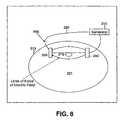
- FIG. 8is a cross-sectional illustration of the insulated electrodes implanted within the body for treating a tumor or the like;
- FIG. 9is a cross-sectional illustration of the insulated electrodes implanted within the body for treating a tumor or the like.
- FIGS. 10A-10Dare cross-sectional illustrations of various constructions of the insulated electrodes of the apparatus of FIG. 5 ;
- FIG. 11is a front elevational view in partial cross-section of two insulated electrodes being arranged about a human torso for treatment of a tumor container within the body, e.g., a tumor associated with lung cancer;
- FIGS. 12A-12Care cross-sectional illustrations of various insulated electrodes with and without protective members formed as a part of the construction thereof;
- FIG. 13is a schematic diagram of insulated electrodes that are arranged for focusing the electric field at a desired target while leaving other areas in low field density (i.e., protected areas);
- FIG. 15is a partial section of a hat according to an exemplary embodiment having a recessed section for receiving one or more insulated electrodes;
- FIG. 16is a cross-sectional view of the hat of FIG. 15 placed on a head and illustrating a biasing mechanism for applying a force to the insulated electrode to ensure the insulated electrode remains in contact against the head;
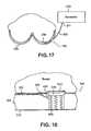
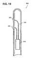
- FIG. 18is a cross-sectional view of a section of the article of clothing of FIG. 17 illustrating a biasing mechanism for biasing the insulated electrode in direction to ensure the insulated electrode is placed proximate to a skin surface where treatment is desired;
- FIG. 20is an elevational view of an unwrapped collar according to one exemplary embodiment for placement around a neck for treating a tumor or the like in this area when the collar is wrapped around the neck;
- FIG. 21is a cross-sectional view of two insulated electrodes with conductive gel members being arranged about a body, with the electric field lines being shown;
- FIG. 22is a cross-sectional view of the arrangement of FIG. 21 illustrating a point of insulation breakdown in one insulated electrode
- FIG. 23is a cross-sectional view of an arrangement of at least two insulated electrodes with conductive gel members being arranged about a body for treatment of a tumor or the like, wherein each conductive gel member has a feature for minimizing the effects of an insulation breakdown in the insulated electrode;
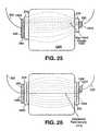
- FIG. 24is a cross-sectional view of another arrangement of at least two insulated electrodes with conductive gel members being arranged about a body for treatment of a tumor or the like, wherein a conductive member is disposed within the body near the tumor to create a region of increased field density;
- FIG. 25is a cross-sectional view of an arrangement of two insulated electrodes of varying sizes disposed relative to a body.
- FIG. 26is a cross-sectional view of an arrangement of at least two insulated electrodes with conductive gel members being arranged about a body for treatment of a tumor or the like, wherein each conductive gel member has a feature for minimizing the effects of an insulation breakdown in the insulated electrode.
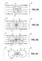
- FIGS. 27A-Cshow a configuration of electrodes that facilitates the application of an electric field in different directions.
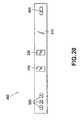
- FIG. 28shows a three-dimensional arrangement of electrodes about a body part that facilitates the application of an electric field in different directions.
- FIGS. 29A and 29Bare graphs of the efficiency of the cell destruction process as a function of field strength for melanoma and glioma cells, respectively.
- FIGS. 30A and 30Bare graphs that show how the cell destruction efficiency is a function of the frequency of the applied field for melanoma and glioma cells, respectively.
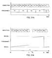
- FIG. 31Ais a graphical representation of the sequential application of a plurality of frequencies in a plurality of directions.
- FIG. 31Bis a graphical representation of the sequential application of a sweeping frequency in a plurality of directions.
- FIGS. 1A-1Eschematically illustrate various stages of a cell division process.
- FIG. 1Aillustrates a cell 10 at its normal geometry, which can be generally spherical (as illustrated in the drawings), ellipsoidal, cylindrical, “pancake-like” or any other cell geometry, as is known in the art.
- FIGS. 1B-1Dillustrate cell 10 during different stages of its division process, which results in the formation of two new cells 18 and 20 , shown in FIG. 1E .
- the division process of cell 10is characterized by a slowly growing cleft 12 which gradually separates cell 10 into two units, namely sub-cells 14 and 16 , which eventually evolve into new cells 18 and 20 ( FIG. 1E ).
- the division processis characterized by a transient period during which the structure of cell 10 is basically that of the two sub-cells 14 and 16 interconnected by a narrow “bridge” 22 containing cell material (cytoplasm surrounded by cell membrane).
- FIGS. 2A and 2Bschematically illustrate non-dividing cell 10 being subjected to an electric field produced by applying an alternating electric potential, at a relatively low frequency and at a relatively high frequency, respectively.
- Cell 10includes intracellular organelles, e.g., a nucleus 30 .
- Alternating electric potentialis applied across electrodes 28 and 32 that can be attached externally to a patient at a predetermined region, e.g., in the vicinity of the tumor being treated.
- a conductive environmenthereinafter referred to as a “volume conductor” consisting mostly of electrolytic inter-cellular liquid.
- the specific distribution of the electric field lineswhich is substantially consistent with the direction of current flow in this instance, depends on the geometry and the electric properties of the system components, e.g., the relative conductivities and dielectric constants of the system components, that can be frequency dependent. For low frequencies, e.g., frequencies lower than 10 KHz, the conductance properties of the components completely dominate the current flow and the field distribution, and the field distribution is generally as depicted in FIG. 2A . At higher frequencies, e.g., at frequencies of between 10 KHz and 1 MHz, the dielectric properties of the components becomes more significant and eventually dominate the field distribution, resulting in field distribution lines as depicted generally in FIG. 2B .
- the dielectric properties of the various componentsare not significant in determining and computing the field distribution. Therefore, as a first approximation, with regard to the electric field distribution, the system can be reasonably represented by the relative impedances of its various components. Using this approximation, the intercellular (i.e., extracellular) fluid and the intracellular fluid each has a relatively low impedance, while the cell membrane 11 has a relatively high impedance. Thus, under low frequency conditions, only a fraction of the electric field lines (or currents induced by the electric field) penetrate membrane 11 of the cell 10 .
- the impedance of membrane 11 relative to the intercellular and intracellular fluidsdecreases, and thus, the fraction of currents penetrating the cells increases significantly. It should be noted that at very high frequencies, i.e., above 1 MHz, the membrane capacitance can short the membrane resistance and, therefore, the total membrane resistance can become negligible.
- the electric field linespenetrate cell 10 from a portion of the membrane 11 closest to one of the electrodes generating the current, e.g., closest to positive electrode 28 (also referred to herein as “source”).
- the current flow pattern across cell 10is generally uniform because, under the above approximation, the field induced inside the cell is substantially homogeneous.
- the currentsexit cell 10 through a portion of membrane 11 closest to the opposite electrode, e.g., negative electrode 32 (also referred to herein as “sink”).
- field lines and current flowcan depend on a number of factors, for example, on the frequency of the applied electric potential and on whether electrodes 28 and 32 are electrically insulated.
- insulated electrodesapplying a DC or low frequency alternating voltage, there is practically no current flow along the lines of the electric field.
- the displacement currentsare induced in the tissue due to charging and discharging of the electrode insulation and the cell membranes (which act as capacitors to a certain extent), and such currents follow the lines of the electric field.
- Fields generated by non-insulated electrodesin contrast, always generate some form of current flow, specifically, DC or low frequency alternating fields generate conductive current flow along the field lines, and high frequency alternating fields generate both conduction and displacement currents along the field lines.
- the electric fields that are usedare alternating fields having frequencies that are in the range from about 50 KHz to about 500 KHz, and preferably from about 100 KHz to about 300 KHz.
- these type of electric fieldsare also referred to below as “TC fields”, which is an abbreviation of “Tumor Curing electric fields”, since these electric fields fall into an intermediate category (between high and low frequency ranges) that have bio-effective field properties while having no meaningful stimulatory and thermal effects.
- TC fieldsis an abbreviation of “Tumor Curing electric fields”
- These frequenciesare sufficiently low so that the system behavior is determined by the system's Ohmic (conductive) properties but sufficiently high enough not to have any stimulation effect on excitable tissues.
- Such a systemconsists of two types of elements, namely, the intercellular, or extracellular fluid, or medium and the individual cells.
- the intercellular fluidis mostly an electrolyte with a specific resistance of about 40-100 Ohm*cm.
- the cellsare characterized by three elements, namely (1) a thin, highly electric resistive membrane that coats the cell; (2) internal cytoplasm that is mostly an electrolyte that contains numerous macromolecules and micro-organelles, including the nucleus; and (3) membranes, similar in their electric properties to the cell membrane, cover the micro-organelles.
- FIG. 2schematically depicts the resulting field distribution in the system.
- the lines of forcewhich also depict the lines of potential current flow across the cell volume mostly in parallel with the undistorted lines of force (the main direction of the electric field).
- the field inside the cellsis mostly homogeneous.
- the fraction of the field or current that penetrates the cellsis determined by the cell membrane impedance value relative to that of the extracellular fluid. Since the equivalent electric circuit of the cell membrane is that of a resistor and capacitor in parallel, the impedance is a function of the frequency. The higher the frequency, the lower the impedance, the larger the fraction of penetrating current and the smaller the field distortion (Rotshenker S. & Y. Palti, Changes in fraction of current penetrating an axon as a function of duration of stimulating pulse , J. Theor. Biol. 41; 401-407 (1973).
- FIGS. 3A-3Cschematically illustrate the electric current flow pattern in cell 10 during its division process, under the influence of alternating fields (TC fields) in the frequency range from about 100 KHz to about 300 KHz in accordance with one exemplary embodiment.
- the field lines or induced currentspenetrate cell 10 through a part of the membrane of sub-cell 16 closer to electrode 28 . However, they do not exit through the cytoplasm bridge 22 that connects sub-cell 16 with the newly formed yet still attached sub-cell 14 , or through a part of the membrane in the vicinity of the bridge 22 .
- the direction of movement of polarized and charged objectsis towards the higher density electric field lines, i.e., towards the cytoplasm bridge 22 between sub-cells 14 and 16 .
- all intracellular organellesfor example, nuclei 24 and 26 of sub-cells 14 and 16 , respectively, are polarizable and, thus, such intracellular organelles are electrically forced in the direction of the bridge 22 . Since the movement is always from lower density currents to the higher density currents, regardless of the field polarity, the forces applied by the alternating electric field to organelles, such as nuclei 24 and 26 , are always in the direction of bridge 22 .
- dielectrophoresisa phenomenon referred to as “dielectrophoresis” is described extensively in literature, e.g., in C. L. Asbury & G. van den Engh, Biophys. J. 74, 1024-1030, 1998, the disclosure of which is hereby incorporated by reference in its entirety.
- the movement of the organelles 24 and 26 towards the bridge 22disrupts the structure of the dividing cell, change the concentration of the various cell constituents and, eventually, the pressure of the converging organelles on bridge membrane 22 results in the breakage of cell membrane 11 at the vicinity of the bridge 22 , as shown schematically in FIG. 3C .
- the ability to break membrane 11 at bridge 22 and to otherwise disrupt the cell structure and organizationcan be enhanced by applying a pulsating AC electric field, rather than a steady AC field.
- FIG. 4a dividing cell 10 is illustrated, at an earlier stage as compared to FIGS. 3A and 3B , under the influence of external TC fields (e.g., alternating fields in the frequency range of about 100 KHz to about 300 KHz), generally indicated as lines 100 , with a corresponding spindle mechanism generally indicated at 120 .
- the lines 120are microtubules that are known to have a very strong dipole moment. This strong polarization makes the tubules, as well as other polar macromolecules and especially those that have a specific orientation within the cells or its surrounding, susceptible to electric fields.
- the present apparatusutilizes insulated electrodes
- the above-mentioned negative effects obtained when conductive electrodes are usedi.e., ion concentration changes in the cells and the formation of harmful agents by electrolysis, do not occur when the present apparatus is used. This is because, in general, no actual transfer of charges takes place between the electrodes and the medium and there is no charge flow in the medium where the currents are capacitive, i.e., are expressed only as rotation of charges, etc.
- FIG. 5is a simple schematic diagram of the electronic apparatus 200 illustrating the major components thereof.
- the electronic apparatus 200generates the desired electric signals (TC signals) in the shape of waveforms or trains of pulses.
- the apparatus 200includes a generator 210 and a pair of conductive leads 220 that are attached at one end thereof to the generator 210 .
- the opposite ends of the leads 220are connected to insulated conductors 230 that are activated by the electric signals (e.g., waveforms).
- the insulated conductors 230are also referred to hereinafter as isolects 230 .
- the apparatus 200includes a temperature sensor 240 and a control box 250 which are both added to control the amplitude of the electric field generated so as not to generate excessive heating in the area that is treated.
- the generator 210generates an alternating voltage waveform at frequencies in the range from about 50 KHz to about 500 KHz (preferably from about 100 KHz to about 300 KHz) (i.e., the TC fields).
- the required voltagesare such that the electric field intensity in the tissue to be treated is in the range of about 0.1 V/cm to about 10 V/cm.
- the actual potential difference between the two conductors in the isolects 230is determined by the relative impedances of the system components, as described below.
- control box 250When the control box 250 is included, it controls the output of the generator 210 so that it will remain constant at the value preset by the user or the control box 250 sets the output at the maximal value that does not cause excessive heating, or the control box 250 issues a warning or the like when the temperature (sensed by temperature sensor 240 ) exceeds a preset limit.
- the leads 220are standard isolated conductors with a flexible metal shield, preferably grounded so that it prevents the spread of the electric field generated by the leads 220 .
- the isolects 230have specific shapes and positioning so as to generate an electric field of the desired configuration, direction and intensity at the target volume and only there so as to focus the treatment.
- the specifications of the apparatus 200 as a whole and its individual componentsare largely influenced by the fact that at the frequency of the present TC fields (50 KHz-500 KHz), living systems behave according to their “Ohmic”, rather than their dielectric properties.
- the only elements in the apparatus 200 that behave differentlyare the insulators of the isolects 230 (see FIGS. 7-9 ).
- the isolects 200consist of a conductor in contact with a dielectric that is in contact with the conductive tissue thus forming a capacitor.
- the details of the construction of the isolects 230is based on their electric behavior that can be understood from their simplified electric circuit when in contact with tissue as generally illustrated in FIG. 6 .
- the potential drop or the electric field distribution between the different componentsis determined by their relative electric impedance, i.e., the fraction of the field on each component is given by the value of its impedance divided by the total circuit impedance.
- the potential drop on element ⁇ V AA/(A+B+C+D+E).
- the impedance of the capacitance of the capacitorsis dominant and determines the field distribution. Therefore, in order to increase the effective voltage drop across the tissues (field intensity), the impedance of the capacitors is to be decreased (i.e., increase their capacitance). This can be achieved by increasing the effective area of the “plates” of the capacitor, decrease the thickness of the dielectric or use a dielectric with high dielectric constant.
- the isolects 230are configured differently depending upon the application in which the isolects 230 are to be used. There are two principle modes for applying the present electric fields (TC fields). First, the TC fields can be applied by external isolects and second, the TC fields can be applied by internal isolects.
- Electric fields (TC fields) that are applied by external isolectscan be of a local type or widely distributed type.
- the first typeincludes, for example, the treatment of skin tumors and treatment of lesions close to the skin surface.
- FIG. 7illustrates an exemplary embodiment where the isolects 230 are incorporated in a skin patch 300 .
- the skin patch 300can be a self-adhesive flexible patch with one or more pairs of isolects 230 .
- the patch 300includes internal insulation 310 (formed of a dielectric material) and the external insulation 260 and is applied to skin surface 301 that contains a tumor 303 either on the skin surface 301 or slightly below the skin surface 301 .
- Tissueis generally indicated at 305 .
- the internal insulation 310must have a relatively high capacity. This can be achieved by a large surface area; however, this may not be desired as it will result in the spread of the field over a large area (e.g., an area larger than required to treat the tumor).
- the internal insulation 310can be made very thin and/or the internal insulation 310 can be of a high dielectric constant. As the skin resistance between the electrodes (labeled as A and E in FIG. 6 ) is normally significantly higher than that of the tissue (labeled as C in FIG. 6 ) underneath it (1-10 K ⁇ vs. 0.1-1 K ⁇ ), most of the potential drop beyond the isolects occurs there.
- the characteristics of the internal insulation 310should be such that they have impedance preferably under 100 K ⁇ at the frequencies of the present TC fields (e.g., 50 KHz to 500 KHz).
- the impedancepreferably under 100 K ⁇ at the frequencies of the present TC fields (e.g., 50 KHz to 500 KHz).
- the impedanceshould be about 10 K Ohms or less, such that over 1% of the applied voltage falls on the tissues, for isolects with a surface area of 10 mm 2 , at frequencies of 200 KHz, the capacity should be on the order of 10 ⁇ 10 F., which means that using standard insulations with a dielectric constant of 2-3, the thickness of the insulating layer 310 should be about 50-100 microns. An internal field 10 times stronger would be obtained with insulators with a dielectric constant of about 20-50.
- Using an insulating material with a high dielectric constantincreases the capacitance of the electrodes, which results in a reduction of the electrodes' impedance to the AC signal that is applied by the generator 1 (shown in FIG. 5 ). Because the electrodes A, E are wired in series with the target tissue C, as shown in FIG. 6 , this reduction in impedance reduces the voltage drop in the electrodes, so that a larger portion of the applied AC voltage appears across the tissue C. Since a larger portion of the voltage appears across the tissue, the voltage that is being applied by the generator 1 can be advantageously lowered for a given field strength in the tissue.
- the desired field strength in the tissue being treatedis preferably between about 0.1 V/cm and about 10 V/cm, and more preferably between about 2 V/cm and 3 V/cm or between about 1 V/cm and about 5 V/cm.
- the dielectric constant used in the electrodeis sufficiently high, the impedance of the electrodes A, E drops down to the same order of magnitude as the series combination of the skin and tissue B, C, D.
- a suitable material with an extremely high dielectric constantis CaCu 3 Ti 4 O 12 , which has a dielectric constant of about 11,000 (measured at 100 kHz). When the dielectric constant is this high, useful fields can be obtained using a generator voltage that is on the order of a few tens of Volts.
- the insulationcan be replaced by very high dielectric constant insulating materials, such as titanium dioxide (e.g., rutile), the dielectric constant can reach values of about 200.
- dielectric constant insulating materialssuch as titanium dioxide (e.g., rutile)
- the dielectric constantcan reach values of about 200.
- some materialsinclude: lithium niobate (LiNbO 3 ), which is a ferroelectric crystal and has a number of applications in optical, pyroelectric and piezoelectric devices; yttrium iron garnet (YIG) is a ferromagnetic crystal and magneto-optical devices, e.g., optical isolator can be realized from this material; barium titanate (BaTiO 3 ) is a ferromagnetic crystal with a large electro-optic effect; potassium tantalate (KTaO 3 ) which is a dielectric crystal (ferroelectric at low temperature) and has very low microwave loss and tunability of dielectric constant at low temperature; and lithium tantalate (LiTaO 3 ) which is a ferroelectric crystal with similar properties as lithium niobate and has utility in electro-optical, pyroelectric and piezoelectric devices.
- LiNbO 3lithium niobate
- YIGyttrium iron garnet
- Insulator ceramics with high dielectric constantsmay also be used, such as a ceramic made of a combination of Lead Magnesium Niobate and Lead Titanate. It will be understood that the aforementioned exemplary materials can be used in combination with the present device where it is desired to use a material having a high dielectric constant.
- the isolects 230can be shaped so as to conform with the body structure and/or (2) an intervening filler 270 (as illustrated in FIG. 10C ), such as a gel, that has high conductance and a high effective dielectric constant, can be added to the structure.
- the shapingcan be pre-structured (see FIG.
- FIGS. 10A- 10 C′illustrate various exemplary configurations for the isolects 230 .
- the exact thickness of the gelis not important so long as it is of sufficient thickness that the gel layer does not dry out during the treatment. In one exemplary embodiment, the thickness of the gel is about 0.5 mm to about 2 mm.
- the gelhas high conductivity, is tacky, and is biocompatible for extended periods of time.
- One suitable gelis AG603 Hydrogel, which is available from AmGel Technologies, 1667 S. Mission Road, Fallbrook, Calif. 92028-4115, USA.
- the dielectric coating of eachshould be very thin, for example from between 1-50 microns. Since the coating is so thin, the isolects 230 can easily be damaged mechanically or undergo dielectric breakdown. This problem can be overcome by adding a protective feature to the isolect's structure so as to provide desired protection from such damage.
- the isolect 230can be coated, for example, with a relatively loose net 340 that prevents access to the surface but has only a minor effect on the effective surface area of the isolect 230 (i.e., the capacity of the isolects 230 (cross section presented in FIG. 12B ). The loose net 340 does not effect the capacity and ensures good contact with the skin, etc.
- the loose net 340can be formed of a number of different materials; however, in one exemplary embodiment, the net 340 is formed of nylon, polyester, cotton, etc.
- a very thin conductive coating 350can be applied to the dielectric portion (insulating layer) of the isolect 230 .
- One exemplary conductive coatingis formed of a metal and more particularly of gold. The thickness of the coating 350 depends upon the particular application and also on the type of material used to form the coating 350 ; however, when gold is used, the coating has a thickness from about 0.1 micron to about 0.1 mm.
- the rim illustrated in FIG. 10can also provide some mechanical protection.
- the dielectric strength of the internal insulation 310determines at what field intensity the insulation will be “shorted” and cease to act as an intact insulation.
- insulatorssuch as plastics, have dielectric strength values of about 100V per micron or more. As a high dielectric constant reduces the field within the internal insulator 310 , a combination of a high dielectric constant and a high dielectric strength gives a significant advantage.
- FIGS. 8 and 9illustrate a second type of treatment using the isolects 230 , namely electric field generation by internal isolects 230 .
- a body to which the isolects 230 are implantedis generally indicated at 311 and includes a skin surface 313 and a tumor 315 .
- the isolects 230can have the shape of plates, wires or other shapes that can be inserted subcutaneously or a deeper location within the body 311 so as to generate an appropriate field at the target area (tumor 315 ).
- the mode of isolects applicationis not restricted to the above descriptions.
- the distance between each member of the pair of isolects 230can be large.
- the pairscan even by positioned opposite sides of a torso 410 , as illustrated in FIG. 11 .
- the arrangement of the isolects 230 in FIG. 11is particularly useful for treating a tumor 415 associated with lung cancer or gastro-intestinal tumors.
- the electric fields (TC fields)spread in a wide fraction of the body.
- the isolects insulating materialshould have minimal dielectric losses at the frequency ranges to be used during the treatment process. This factor can be taken into consideration when choosing the particular frequencies for the treatment.
- the direct heating of the tissueswill most likely be dominated by the heating due to current flow (given by the I*R product).
- the isolect (insulated electrode) 230 and its surroundingsshould be made of materials that facilitate heat losses and its general structure should also facilitate head losses, i.e., minimal structures that block heat dissipation to the surroundings (air) as well as high heat conductivity.
- head lossesi.e., minimal structures that block heat dissipation to the surroundings (air) as well as high heat conductivity.
- Using larger electrodesalso minimizes the local sensation of heating, since it spreads the energy that is being transferred into the patient over a larger surface area.
- the heatingis minimized to the point where the patient's skin temperature never exceeds about 39° C.
- Another way to reduce heatingis to apply the field to the tissue being treated intermittently, by applying a field with a duty cycle between about 20% and about 50% instead of using a continuous field.
- a field with a duty cycle between about 20% and about 50%instead of using a continuous field.
- the fieldwould be repetitively switched on for one second, then switched off for two seconds.
- the efficacy of treatment using a field with a 33% duty cycleis roughly the same as for a field with a duty cycle of 100%.
- the fieldcould be switched on for one hour then switched off for one hour to achieve a duty cycle of 50%.
- switching at a rate of once per hourwould not help minimize short-term heating.
- the effectiveness of the treatmentcan be enhanced by an arrangement of isolects 230 that focuses the field at the desired target while leaving other sensitive areas in low field density (i.e., protected areas).
- the proper placement of the isolects 230 over the bodycan be maintained using any number of different techniques, including using a suitable piece of clothing that keeps the isolects at the appropriate positions.
- FIG. 13illustrates such an arrangement in which an area labeled as “P” represents a protected area. The lines of field force do not penetrate this protected area and the field there is much smaller than near the isolects 230 where target areas can be located and treated well. In contrast, the field intensity near the four poles is very high.
- Exampleserves to illustrate an exemplary application of the present apparatus and application of TC fields; however, this Example is not limiting and does not limit the scope of the present invention in any way.
- the only areas that were visible discernable on the skinwere the marks that represented the points of insertion of the isolects 230 .
- the fact that the tumor was eliminated at the treated sidewas further demonstrated by cutting and inversing the skin so that its inside face was exposed. Such a procedure indicated that the tumor has been substantially, if not completely, eliminated on the treated side of the mouse.
- the success of the treatmentwas also further verified by histopathological examination.
- the present apparatuscan further include a device for rotating the TC field relative to the living tissue.
- the alternating electric potentialapplies to the tissue being treated is rotated relative to the tissue using conventional devices, such as a mechanical device that upon activation, rotates various components of the present system.
- the TC fieldsare applied to different pairs of the insulated electrodes 230 in a consecutive manner.
- the generator 210 and the control system thereofcan be arranged so that signals are sent at periodic intervals to select pairs of insulated electrodes 230 , thereby causing the generation of the TC fields of different directions by these insulated electrodes 230 .
- the signalsare sent at select times from the generator to the insulated electrodes 230 , the TC fields of changing directions are generated consecutively by different insulated electrodes 230 .
- This arrangementhas a number of advantages and is provided in view of the fact that the TC fields have maximal effect when they are parallel to the axis of cell division. Since the orientation of cell division is in most cases random, only a fraction of the dividing cells are affected by any given field. Thus, using fields of two or more orientations increases the effectiveness since it increases the chances that more dividing cells are affected by a given TC field.
- the inventorhas recognized that applying the field in different directions sequentially will increase the overall killing power, because the field orientation that is most effectively in killing dividing cells will be applied to a larger population of the dividing cells.
- a number of examples for applying the field in different directionsare discussed below.
- FIGS. 27A , 27 B, and 27 Cshow a set of 6 electrodes E 1 -E 6 , and how the direction of the field through the target tissue 1510 can be changed by applying the AC signal from the generator 1 (shown in FIG. 1 ) across different pairs of electrodes. For example, if the AC signal is applied across electrodes E 1 and E 4 , the field lines F would be vertical (as shown in FIG. 27A ), and if the signal is applied across electrodes E 2 and E 5 , or across electrodes E 3 and E 6 , the field lines F would be diagonal (as shown in FIGS. 27B and 27C , respectively). Additional field directions can be obtained by applying the AC signal across other pairs of electrodes. For example, a roughly horizontal field could be obtained by applying the signal across electrodes E 2 and E 6 .
- the AC signalis applied between the various pairs of electrodes sequentially.
- An example of this arrangementis to apply the AC signal across electrodes E 1 and E 4 for one second, then apply the AC signal across electrodes E 2 and E 5 for one second, and then apply the AC signal across electrodes E 3 and E 6 for one second.
- This three-part sequenceis then repeated for the desired period of treatment. Because the efficacy in cell-destruction is strongly dependant on the cell's orientation, cycling the field between the different directions increases the chance that the field will be oriented in a direction that favors cell destruction at least part of the time.
- FIGS. 27A-Cis just one of many possible arrangement of multiple electrodes, and many other configurations of three or more electrodes could be used based on the same principles.
- FIG. 28shows how the sequential application of signals across different sets of electrodes can be extended to three dimensions.
- a first array of electrodes A 1 -A 9is arranged around body part 1500
- a last array of electrodes N 1 -N 9is arranged around the body part 1500 a distance W away from the first array. Additional arrays of electrodes may optionally be added between the first array and the last array, but these additional arrays are not illustrated for clarity (so as not to obscure the electrodes A 5 -A 9 and B 5 -B 8 on the back of the body part 1500 ).
- the direction of the field through the target tissuecan be changed by applying the AC signal from the generator 1 (shown in FIG. 1 ) across different pairs of electrodes.
- applying the AC signal between electrodes A 2 and A 7would result in a field in a front-to-back direction between those two electrodes, and applying the AC signal between electrodes A 5 and A 9 would result in a roughly vertical field between those two electrodes.
- applying the AC signal across electrodes A 2 and N 7would generate diagonal field lines in one direction through the body part 1500
- applying the AC signal across electrodes A 2 and B 7would generate diagonal field lines in another direction through the body part.
- Using a three-dimensional array of electrodesalso makes it possible to energize multiple pairs of electrodes simultaneously to induce fields in the desired directions. For example, if suitable switching is provided so that electrodes A 2 through N 2 are all connected to one terminal of the generator, and so that electrodes A 7 through N 7 are all connected to the other terminal of the generator, the resulting field would be a sheet that extends in a front-to-back direction for the entire width W. After the front-to-back field is maintained for a suitable duration (e.g., one second), the switching system (not shown) is reconfigured to connect electrodes A 3 through N 3 to one terminal of the generator, and electrodes A 8 through N 8 to the other terminal of the generator.
- a suitable duratione.g., one second
- the rotating sheet-shaped fieldmay be added (sequentially in time) to the diagonal fields described above, to better target cells that are oriented along those diagonal axes.
- the signalsmay optionally be applied to combinations of electrodes simultaneously in order to form a desired resultant vector.
- a field that is rotated about the X axis by 20° with respect to the initial positioncan be obtained by switching electrodes A 2 through N 2 and A 3 through N 3 all to one terminal of the generator, and switching electrodes A 7 through N 7 and A 8 through N 8 all to the other terminal of the generator.
- Applying the signals to other combinations of electrodeswill result in fields in other directions, as will be appreciated by persons skilled in the relevant arts. If appropriate computer control of the voltages is implemented, the field's direction can even be swept through space in a continuous (i.e., smooth) manner, as opposed to the stepwise manner described above.
- FIGS. 29A and 29Bdepict the results of in vitro experiments that show how the killing power of the applied field against dividing cells is a function of the field strength.
- B16F1 melanoma cellswere subjected to a 100 kHz AC field at different field strengths, for a period of 24 hours at each strength.
- F-98 glioma cellswere subjected to a 200 kHz AC field at different field strengths, for a period of 24 hours at each strength.
- the strength of the field (EF)is measured in Volts per cm.
- the magnitude of the killing effectis expressed in terms of TER, which is which is the ratio of the decrease in the growth rate of treated cells (GRT) compared with the growth rate of control cells (GRc).
- TERGR C - GR T GR C
- FIGS. 30A and 30Bdepict the results of in vitro experiments that show how the killing power of the applied field is a function of the frequency of the field.
- B16F1 melanoma cellsFIG. 30A
- F-98 glioma cellsFIG. 30B
- FIGS. 30A and 30Bshow the change in the growth rate, normalized to the field intensity (TER/EF). Data are shown as mean+SE.
- TER/EFfield intensity
- a field with a frequency of about 120 kHzwould be appropriate for destroying melanoma cells, and a field with a frequency on the order of 200 kHz would be appropriate for destroying glioma cells.
- the cells of any given typewill have the exact same size. Instead, the cells will have a distribution of sizes, with some cells being smaller and some cells being larger. It is believed that the best frequency for damaging a particular cell is related to the physical characteristics (e.g., the size) of that particular cell. Thus, to best damage a population of cells with a distribution of sizes, it can be advantageous to apply a distribution of different frequencies to the population, where the selection of frequencies is optimized based on the expected size distribution of the target cells. For example, the data on FIG. 30B indicates that using two frequencies of 170 kHz and 250 kHz to destroy a population of glioma cells would be more effective than using a single frequency of 200 kHz.
- the various frequenciesmay be applied sequentially in time. For example, in the case of glioma, field frequencies of 100, 150, 170, 200, 250, and 300 kHz may be applied during the first, second, third, fourth, fifth, and sixth minutes of treatment, respectively. That cycle of frequencies would then repeat during each successive six minutes of treatment. Alternatively, the frequency of the field may be swept in a stepless manner from 100 to 300 kHz.
- FIG. 31Ais an example of such a combination using three directions (D 1 , D 2 , and D 3 ) and three frequencies (F 1 , F 2 , and F 3 ).
- FIG. 31Bis an example of such a combination using three directions (D 1 , D 2 , and D 3 ), sweeping the frequency from 100 kHz to 300 kHz. Note that the break in the time axis between t 1 and t 2 provides the needed time for the sweeping frequency to rise to just under 300 kHz.
- the frequency sweeping (or stepping)may be synchronized with directional changes, as shown in FIG. 31A .
- the frequency sweeping (or stepping)may be asynchronous with respect to the directional changes, as shown in FIG. 31B .
- a signal that contains two or more frequencies components simultaneouslyis applied to the electrodes to treat a populations of cells that have a distribution of sizes.
- the various signalswill add by superposition to create a field that includes all of the applied frequency components.
- the article of clothing 500is in the form of a hat or cap or other type of clothing designed for placement on a head of a person.
- a head 502is shown with the hat 500 being placed thereon and against a skin surface 504 of the head 502 .
- An intra-cranial tumor or the like 510is shown as being formed within the head 502 underneath the skin surface 504 thereof.
- the hat 500is therefore intended for placement on the head 502 of a person who has a tumor 510 or the like.
- the insulated electrodes 230 in this embodimentare specifically contoured and arranged for a specific application.
- the treatment of intra-cranial tumors or other lesions or the liketypically requires a treatment that is of a relatively long duration, e.g., days to weeks, and therefore, it is desirable to provide as much comfort as possible to the patient.
- the hat 500is specifically designed to provide comfort during the lengthy treatment process while not jeopardizing the effectiveness of the treatment.
- the hat 500includes a predetermined number of insulated electrodes 230 that are preferably positioned so as to produce the optimal TC fields at the location of the tumor 510 .
- the lines of force of the TC fieldare generally indicated at 520 .
- the tumor 510is positioned within these lines of force 520 .
- the insulated electrodes 230are positioned within the hat 500 such that a portion or surface thereof is free to contact the skin surface 504 of the head 502 .
- the insulated electrodes 230are placed in contact with the skin surface 504 of the head 502 in positions that are selected so that the TC fields generated thereby are focused at the tumor 510 while leaving surrounding areas in low density.
- hair on the head 502is shaved in selected areas to permit better contact between the insulated electrodes 230 and the skin surface 504 ; however, this is not critical.
- the hat 500preferably includes a mechanism 530 that applies a force to the insulated electrodes 230 so that they are pressed against the skin surface 502 .
- the mechanism 530can be of a biasing type that applies a biasing force to the insulated electrodes 230 to cause the insulated electrodes 230 to be directed outwardly away from the hat 500 .
- the mechanism 530can slightly recoil to provide a comfortable fit between the insulated electrodes 230 and the head 502 .
- the mechanism 530is a spring based device that is disposed within the hat 500 and has one section that is coupled to and applies a force against the insulated electrodes 230 .
- the insulated electrodes 230are coupled to the generator 210 by means of conductors 220 .
- the generator 210can be either disposed within the hat 500 itself so as to provide a compact, self-sufficient, independent system or the generator 210 can be disposed external to the hat 500 with the conductors 220 exiting the hat 500 through openings or the like and then running to the generator 210 .
- the generator 210can be located in any number of different locations, some of which are in close proximity to the hat 500 itself, while others can be further away from the hat 500 .
- the generator 210can be disposed within a carrying bag or the like (e.g., a bag that extends around the patient's waist) which is worn by the patient or it can be strapped to an extremity or around the torso of the patient.
- the generator 210can also be disposed in a protective case that is secured to or carried by another article of clothing that is worn by the patient.
- the protective casecan be inserted into a pocket of a sweater, etc.
- FIG. 14illustrates an embodiment where the generator 210 is incorporated directly into the hat 500 .
- a number of insulated electrodes 230 along with the mechanism 530are preferably formed as an independent unit, generally indicated at 540 , that can be inserted into the hat 500 and electrically connected to the generator (not shown) via the conductors (not shown).
- the patientcan easily insert and/or remove the units 540 from the hat 500 when they may need cleaning, servicing and/or replacement.
- the hat 500is constructed to include select areas 550 that are formed in the hat 500 to receive and hold the units 540 .
- each area 550is in the form of an opening (pore) that is formed within the hat 500 .
- the unit 540has a body 542 and includes the mechanism 530 and one or more insulated electrodes 230 .
- the mechanism 530is arranged within the unit 540 so that a portion thereof (e.g., one end thereof) is in contact with a face of each insulated electrode 230 such that the mechanism 530 applies a biasing force against the face of the insulated electrode 230 .
- the hat 500can include pivotable clip members that pivot between an open position in which the opening 550 is free and a closed position in which the pivotable clip members engage portions (e.g., peripheral edges) of the insulated electrodes to retain and hold the insulated electrodes 230 in place. To remove the insulated electrodes 230 , the pivotable clip members are moved to the open position. In the embodiment illustrated in FIG.
- the insulated electrodes 230are retained within the openings 550 by an adhesive element 560 which in one embodiment is a two sided self-adhesive rim member that extends around the periphery of the insulated electrode 230 .
- an adhesive element 560which in one embodiment is a two sided self-adhesive rim member that extends around the periphery of the insulated electrode 230 .
- a protective cover of one side of the adhesive rim 560is removed and it is applied around the periphery of the exposed face of the insulated electrode 230 , thereby securely attaching the adhesive rim 560 to the hat 500 and then the other side of the adhesive rim 560 is removed for application to the skin surface 504 in desired locations for positioning and securing the insulated electrode 230 to the head 502 with the tumor being positioned relative thereto for optimization of the TC fields.
- one side of the adhesive rim 560is in contact with and secured to the skin surface 540 , this is why it is desirable for the head
- the adhesive rim 560is designed to securely attach the unit 540 within the opening 550 in a manner that permits the unit 540 to be easily removed from the hat 500 when necessary and then replaced with another unit 540 or with the same unit 540 .
- the unit 540includes the biasing mechanism 530 for pressing the insulated electrode 230 against the skin surface 504 when the hat 500 is worn.
- the unit 540can be constructed so that side opposite the insulated electrode 230 is a support surface formed of a rigid material, such as plastic, so that the biasing mechanism 530 (e.g., a spring) can be compressed therewith under the application of force and when the spring 530 is in a relaxed state, the spring 530 remains in contact with the support surface and the applies a biasing force at its other end against the insulated electrode 230 .
- the biasing mechanism 530e.g., spring
- the biasing mechanism 530preferably has a contour corresponding to the skin surface 504 so that the insulated electrode 230 has a force applied thereto to permit the insulated electrode 230 to have a contour complementary to the skin surface 504 , thereby permitting the two to seat flushly against one another.
- the mechanism 530can be a spring, there are a number of other embodiments that can be used instead of a spring.
- the mechanism 530can be in the form of an elastic material, such as a foam rubber, a foam plastic, or a layer containing air bubbles, etc.
- the unit 540has an electric connector 570 that can be hooked up to a corresponding electric connector, such as a conductor 220 , that is disposed within the hat 500 .
- the conductor 220connects at one end to the unit 540 and at the other end is connected to the generator 210 .
- the generator 210can be incorporated directly into the hat 500 or the generator 210 can be positioned separately (remotely) on the patient or on a bedside support, etc.
- a coupling agentsuch as a conductive gel
- a coupling agentis preferably used to ensure that an effective conductive environment is provided between the insulated electrode 230 and the skin surface 504 .
- Suitable gel materialshave been disclosed hereinbefore in the discussion of earlier embodiments.
- the coupling agentis disposed on the insulated electrode 230 and preferably, a uniform layer of the agent is provided along the surface of the electrode 230 .
- One of the reasons that the units 540 need replacement at periodic timesis that the coupling agent needs to be replaced and/or replenished. In other words, after a predetermined time period or after a number of uses, the patient removes the units 540 so that the coupling agent can be applied again to the electrode 230 .
- FIGS. 17 and 18illustrate another article of clothing which has the insulated electrodes 230 incorporated as part thereof.
- a bra or the like 700is illustrated and includes a body that is formed of a traditional bra material, generally indicated at 705 , to provide shape, support and comfort to the wearer.
- the bra 700also includes a fabric support layer 710 on one side thereof.
- the support layer 710is preferably formed of a suitable fabric material that is constructed to provide necessary and desired support to the bra 700 .
- the bra 700includes one or more insulated electrodes 230 disposed within the bra material 705 .
- the one or more insulated electrodesare disposed along an inner surface of the bra 700 opposite the support 710 and are intended to be placed proximate to a tumor or the like that is located within one breast or in the immediately surrounding area.
- the insulated electrodes 230 in this embodimentare specifically constructed and configured for application to a breast or the immediate area.
- the insulated electrodes 230 used in this applicationdo not have a planar surface construction but rather have an arcuate shape that is complementary to the general curvature found in a typical breast.
- a lining 720is disposed across the insulated electrodes 230 so as to assist in retaining the insulated electrodes in their desired locations along the inner surface for placement against the breast itself.
- the lining 720can be formed of any number of thin materials that are comfortable to wear against one's skin and in one exemplary embodiment, the lining 720 is formed of a fabric material.
- the bra 700also preferably includes a biasing mechanism 800 as in some of the earlier embodiments.
- the biasing mechanism 800is disposed within the bra material 705 and extends from the support 710 to the insulated electrode 230 and applies a biasing force to the insulated electrode 230 so that the electrode 230 is pressed against the breast. This ensures that the insulated electrode 230 remains in contact with the skin surface as opposed to lifting away from the skin surface, thereby creating a gap that results in a less effective treatment since the gap diminishes the efficiency of the TC fields.
- the biasing mechanism 800can be in the form of a spring arrangement or it can be an elastic material that applies the desired biasing force to the insulated electrodes 230 so as to press the insulated electrodes 230 into the breast.
- the biasing mechanism 800applies a force against the insulated electrodes 230 and when the patient places the bra 700 on their body, the insulated electrodes 230 are placed against the breast which itself applies a force that counters the biasing force, thereby resulting in the insulated electrodes 230 being pressed against the patient's breast.
- the biasing mechanism 800is in the form of springs that are disposed within the bra material 705 .
- a conductive gel 810can be provided on the insulated electrode 230 between the electrode and the lining 720 .
- the conductive gel layer 810is formed of materials that have been previously described herein for performing the functions described above.
- An electric connector 820is provided as part of the insulated electrode 230 and electrically connects to the conductor 220 at one end thereof, with the other end of the conductor 220 being electrically connected to the generator 210 .
- the conductor 220runs within the bra material 705 to a location where an opening is formed in the bra 700 .
- the conductor 220extends through this opening and is routed to the generator 210 , which in this embodiment is disposed in a location remote from the bra 700 .
- the generator 210can be disposed within the bra 700 itself in another embodiment.
- the bra 700can have a compartment formed therein which is configured to receive and hold the generator 210 in place as the patient wears the bra 700 .
- the compartmentcan be covered with a releasable strap that can open and close to permit the generator 210 to be inserted therein or removed therefrom.
- the strapcan be formed of the same material that is used to construct the bra 700 or it can be formed of some other type of material.
- the strapcan be releasably attached to the surrounding bra body by fastening means, such as a hook and loop material, thereby permitting the patient to easily open the compartment by separating the hook and loop elements to gain access to the compartment for either inserting or removing the generator 210 .
- the generator 210also has a connector 211 for electrical connection to the conductor 220 and this permits the generator 210 to be electrically connected to the insulated electrodes 230 .
- the insulated electrodes 230are arranged in the bra 700 to focus the electric field (TC fields) on the desired target (e.g., a tumor).
- TC fieldselectric field
- the location of the insulated electrodes 230 within the bra 700will vary depending upon the location of the tumor.
- the physicianwill then devise an arrangement of insulated electrodes 230 and the bra 700 is constructed in view of this arrangement so as to optimize the effects of the TC fields on the target area (tumor).
- the number and position of the insulated electrodes 230will therefore depend upon the precise location of the tumor or other target area that is being treated.
- the exact size and shape of the insulated electrodes 230can likewise vary. For example, if the insulated electrodes 230 are placed on the bottom section of the bra 700 as opposed to a more central location, the insulated electrodes 230 will have different shapes since the shape of the breast (as well as the bra) differs in these areas.
- FIG. 19illustrates yet another embodiment in which the insulated electrodes 230 are in the form of internal electrodes that are incorporated into in the form of a probe or catheter 600 that is configured to enter the body through a natural pathway, such as the urethra, vagina, etc.
- the insulated electrodes 230are disposed on an outer surface of the probe 600 and along a length thereof.
- the conductors 220are electrically connected to the electrodes 230 and run within the body of the probe 600 to the generator 210 which can be disposed within the probe body or the generator 210 can be disposed independent of the probe 600 in a remote location, such as on the patient or at some other location close to the patient.
- the probe 600can be configured to penetrate the skin surface or other tissues to reach an internal target that lies within the body.
- the probe 600can penetrate the skin surface and then be positioned adjacent to or proximate to a tumor that is located within the body.
- the probe 600is inserted through the natural pathway and then is positioned in a desired location so that the insulated electrodes 230 are disposed near the target area (i.e., the tumor).
- the generator 210is then activated to cause the insulated electrodes 230 to generate the TC fields which are applied to the tumor for a predetermined length of time.
- the illustrated probe 600is merely exemplary in nature and that the probe 600 can have other shapes and configurations so long as they can perform the intended function.
- the conductors (e.g., wires) leading from the insulated electrodes 230 to the generator 210are twisted or shielded so as not to generate a field along the shaft.
- the probescan contain only one insulated electrode while the other can be positioned on the body surface.
- This external electrodeshould be larger or consist of numerous electrodes so as to result in low lines of force-current density so as not to affect the untreated areas.
- the placing of electrodesshould be designed to minimize the field at potentially sensitive areas.
- the external electrodesmay be held against the skin surface by a vacuum force (e.g., suction).
- FIG. 20illustrates yet another embodiment in which a high standing collar member 900 (or necklace type structure) can be used to treat thyroid, parathyroid, laryngeal lesions, etc.
- FIG. 20illustrates the collar member 900 in an unwrapped, substantially flat condition.
- the insulated electrodes 230are incorporated into a body 910 of the collar member 900 and are configured for placement against a neck area of the wearer.
- the insulated electrodes 230are coupled to the generator 210 according to any of the manner described hereinbefore and it will be appreciated that the generator 210 can be disposed within the body 910 or it can be disposed in a location external to the body 910 .
- the collar body 910can be formed of any number of materials that are traditionally used to form collars 900 that are disposed around a person's neck.
- the collar 900preferably includes a means 920 for adjusting the collar 900 relative to the neck.
- complementary fastenerscan be disposed on ends of the collar 900 to permit adjustment of the collar diameter.
- the construction of the present devicesare particularly well suited for applications where the devices are incorporated into articles of clothing to permit the patient to easily wear a traditional article of clothing while at the same time the patient undergoes treatment.
- an extra level of comfortcan be provided to the patient and the effectiveness of the treatment can be increased by incorporating some or all of the device components into the article of clothing.
- the precise article of clothing that the components are incorporated intowill obviously vary depending upon the target area of the living tissue where tumor, lesion or the like exists.
- an article of clothing in the form of a sock-like structure or wrapcan be provided and is configured to be worn around the testicle area of the patient in such a manner that the insulated electrodes thereof are positioned relative to the tumor such that the TC fields are directed at the target tissue.
- the precise nature or form of the article of clothingcan vary greatly since the device components can be incorporated into most types of articles of clothing and therefore, can be used to treat any number of different areas of the patient's body where a condition may be present.
- FIGS. 21-22in which another aspect of the present device is shown.
- a body 1000such as any number of parts of a human or animal body, is illustrated.
- two or more insulated electrodes 230are disposed in proximity to the body 1000 for treatment of a tumor or the like (not shown) using TC fields, as has been previously described in great detail in the above discussion of other embodiments.
- the insulated electrode 230has a conductive component and has external insulation 260 that surrounds the conductive component thereof.
- Each insulated electrode 230is preferably connected to a generator (not shown) by the lead 220 .
- a conductive filler materiale.g., conductive gel member 270
- the insulated electrodes 230are spaced apart from one another and when the generator is actuated, the insulated electrodes 230 generate the TC fields that have been previously described in great detail.
- the lines of the electric field (TC field)are generally illustrated at 1010 . As shown, the electric field lines 1010 extend between the insulated electrodes 230 and through the conductive gel member 270 .
- the external insulation 260 of the insulated electrode 230can begin to breakdown at any given location thereof.
- FIG. 22illustrates that the external insulation 260 of one of the insulated electrodes 230 has experienced a breakdown 1020 at a face thereof which is adjacent the conductive gel member 270 .
- the breakdown 1020 of the external insulation 260results in the formation of a strong current flow-current density at this point (i.e., at the breakdown 1020 ).
- the increased current densityis depicted by the increased number of electric field lines 1010 and the relative positioning and distance between adjacent electric field lines 1010 .
- an overheated area 1030is illustrated and is a region or area of the tissues/skin where an increased current density exits due to the breakdown 1020 in the external insulation 260 .
- a patientcan experience discomfort and pain in this area 1030 due to the strong current that exists in the area and the increased heat and possible burning sensation that exist in area 1030 .
- FIG. 23illustrates yet another embodiment in which a further application of the insulated electrodes 230 is shown.
- the conductive gel member 270 that is disposed between the insulated electrode 230 and the body 1000includes a conductor 1100 that is floating in that the gel material forming the member 270 completely surrounds the conductor 1100 .
- the conductor 1100is a thin metal sheet plate that is disposed within the conductor 1100 .
- a conductorsuch as the plate 1100
- the conductor 1100practically has no effect on the field (except that the two opposing faces of the conductor 1100 are equipotential and the corresponding equipotentials are slightly shifted).
- the conductor 1100is disposed parallel to the electric field, there is a significant distortion of the electric field.
- the area in the immediate proximity of the conductor 1100is not equipotential, in contrast to the situation where there is no conductor 1100 present.
- the conductor 1100When the conductor 1100 is disposed within the gel member 270 , the conductor 1100 will typically not effect the electric field (TC field) for the reasons discussed above, namely that the conductor 1100 is normal to the lines of the electric field.
- the conductor 1100causes the current to spread throughout the conductor 1100 and then exit from the whole surface of the conductor 1100 so that the current reaches the body 1000 with a current density that is neither high nor low. Thus, the current that reaches the skin will not cause discomfort to the patient even when there has been a breakdown in the insulation 260 of the insulated electrode 230 . It is important that the conductor 1100 is not grounded as this would cause it to abolish the electric field beyond it. Thus, the conductor 1100 is “floating” within the gel member 270 .
- the conductor 1100If the conductor 1100 is introduced into the body tissues 1000 and is not disposed parallel to the electric field, the conductor 100 will cause distortion of the electric field.
- the distortioncan cause spreading of the lines of force (low field density-intensity) or concentration of the lines of field (higher density) of the electric field, according to the particular geometries of the insert and its surroundings, and thus, the conductor 1100 can exhibit, for example, a screening effect.
- the conductor 1100completely encircles an organ 1101 , the electric field in the organ itself will be zero since this type of arrangement is a Faraday cage.
- a conductive net or similar structurecan be used to cover, completely or partially, the organ, thereby resulting in the electric field in the organ itself being zero or about zero.
- a netcan be made of a number of conductive wires that are arranged relative to one another to form the net or a set of wires can be arranged to substantially encircle or otherwise cover the organ 1101 .
- an organ 1103 to be treated(the target organ) is not covered with a member having a Faraday cage effect but rather is disposed in the electric field 1010 (TC fields).
- FIG. 24illustrates an embodiment where the conductor 1100 is disposed within the body (i.e., under the skin) and it is located near a target (e.g., a target organ).
- a targete.g., a target organ.
- high field densityof the TC fields
- another nearby organcan be protected by disposing the above described protective conductive net or the like around this nearby organ so as to protect this organ from the fields.
- a high field density conditioncan be provided near or at the target.
- the conductor 1100permits the TC fields to be focused at a particular area (i.e., a target).
- the gel members 260can each include a conductor as described with reference to FIG. 23 .
- the conductor in the gel member 260protects the skin surface (tissues) from any side effects that may be realized if a breakdown in the insulation of the insulated electrode 230 occurs.
- the conductor 1100creates a high field density near the target.
- a first insulated electrode 1200 and a second insulated electrode 1210are provided and are disposed about a body 1300 .
- Each insulated electrodeincludes a conductor that is preferably surrounded by an insulating material, thus the term “insulated electrode”.
- the conductive gel member 270is provided between each of the first and second electrodes 1200 , 1210 and the body 1300 . Electric field lines are generally indicated at 1220 for this type of arrangement.
- the first insulated electrode 1200has dimensions that are significantly greater than the dimensions of the second insulated electrode 1210 (the conductive gel member for the second insulated electrode 1210 will likewise be smaller).
- the pattern of the electric field lines 1220is varied. More specifically, the electric field tapers inwardly toward the second insulated electrode 1210 due to the smaller dimensions of the second insulated electrode 1210 .
- An area of high field densityforms near the interface between the gel member 270 associated with the second insulated electrode 1210 and the skin surface. The various components of the system are manipulated so that the tumor within the skin or on the skin is within this high field density so that the area to be treated (the target) is exposed to electric field lines of a higher field density.
- FIG. 26also illustrates a tapering TC field when a conductor 1400 (e.g., a conductive plate) is disposed in each of the conductive gel members 270 .
- a conductor 1400e.g., a conductive plate
- the size of the gel members 270 and the size of the conductors 1400are the same or about the same despite the differences in the sizes of the insulated electrodes 1200 , 1210 .
- the conductors 1400again can be characterized as “floating plates” since each conductor 1400 is surrounded by the material that forms the gel member 270 . As shown in FIG.
- the decrease in the field densityis generally indicated at 1410 .
- a very inhomogeneous tapering fieldgenerally indicated at 1420 , changing from very low density to very high density is formed between the one conductor 1400 and the insulated electrode 1210 .
- One benefit of this exemplary configurationis that it permits the size of the insulated electrode to be reduced without causing an increase in the nearby field density.
- Electrodes that having very high dielectric constant insulationcan be very expensive.
- Some insulated electrodesfor example, can cost $500.00 or more; and further, the price is sensitive to the particular area of treatment. Thus, a reduction in the size of the insulated electrodes directly leads to a reduction in cost.
- tumorrefers to a malignant tissue comprising transformed cells that grow uncontrollably.
- Tumorsinclude leukemias, lymphomas, myelomas, plasmacytomas, and the like; and solid tumors.
- solid tumorsinclude sarcomas and carcinomas such as, but not limited to: fibrosarcoma, myxosarcoma, liposarcoma, chondrosarcoma, osteogenic sarcoma, chordoma, angiosarcoma, endotheliosarcoma, lymphangiosarcoma, lymphangioendotheliosarcoma, synovioma, mesothelioma, Ewing's tumor, leiomyosarcoma, rhabdomyosarcoma, colon carcinoma, pancreatic cancer, breast cancer, ovarian cancer, prostate cancer, squamous cell carcinoma, basal cell carcinoma, adenocarcinom
- the inventionis particularly advantageous for treating brain tumors, which are difficult to treat with surgery and radiation, and often inaccessible to chemotherapy or gene therapies.
- the present inventionis suitable for use in treating skin and breast tumors because of the ease of localized treatment provided by the present invention.
- the present inventioncan control uncontrolled growth associated with non-malignant or pre-malignant conditions, and other disorders involving inappropriate cell or tissue growth by application of an electric field in accordance with the invention to the tissue undergoing inappropriate growth.
- the inventionis useful for the treatment of arteriovenous (AV) malformations, particularly in intracranial sites.
- AVarteriovenous
- the inventionmay also be used to treat psoriasis, a dermatologic condition that is characterized by inflammation and vascular proliferation; and benign prostatic hypertrophy, a condition associated with inflammation and possibly vascular proliferation. Treatment of other hyperproliferative disorders is also contemplated.
- undesirable fibroblast and endothelial cell proliferation associated with wound healing, leading to scar and keloid formation after surgery or injury, and restenosis after angioplasty or placement of coronary stentscan be inhibited by application of an electric field in accordance with the present invention.
- the non-invasive nature of this inventionmakes it particularly desirable for these types of conditions, particularly to prevent development of internal scars and adhesions, or to inhibit restenosis of coronary, carotid, and other important arteries.
- the above-described embodimentsmay also be used prophylactically to prevent tumors from ever reaching a detectable size in the first place.
- the bra embodiment described above in connection with FIGS. 17 and 18may be worn by a woman for an 8 hour session every day for a week, with the week-long course of treatment being repeated every few months to kill any cells that have become cancerous and started to proliferate.
- This mode of usageis particularly appropriate for people who are at high risk for a particular type of cancer (e.g., women with a strong history of breast cancer in their families, or people who have survived a bout of cancer and are at risk of a relapse).
- the course of prophylactic treatmentmay be tailored based on the type of cancer being targeted and/or to suit the convenience of the patient. For example, undergoing a four 16 hour sessions during the week of treatment may be more convenient for some patients than seven 8 hour session, and may be equally effective.
- the present inventionprovides an effective, simple method of selectively destroying dividing cells, e.g., tumor cells and parasitic organisms, while non-dividing cells or organisms are left affected by application of the method on living tissue containing both types of cells or organisms.
- the present inventiondoes not damage the normal cells or organisms.
- the present inventiondoes not discriminate based upon cell type (e.g., cells having differing sizes) and therefore may be used to treat any number of types of sizes having a wide spectrum of characteristics, including varying dimensions.
Landscapes
- Health & Medical Sciences (AREA)
- Life Sciences & Earth Sciences (AREA)
- Animal Behavior & Ethology (AREA)
- General Health & Medical Sciences (AREA)
- Engineering & Computer Science (AREA)
- Biomedical Technology (AREA)
- Nuclear Medicine, Radiotherapy & Molecular Imaging (AREA)
- Radiology & Medical Imaging (AREA)
- Veterinary Medicine (AREA)
- Public Health (AREA)
- Orthopedic Medicine & Surgery (AREA)
- Cell Biology (AREA)
- Micro-Organisms Or Cultivation Processes Thereof (AREA)
- Electrotherapy Devices (AREA)
- Apparatus Associated With Microorganisms And Enzymes (AREA)
- Immobilizing And Processing Of Enzymes And Microorganisms (AREA)
Abstract
Description
The experimental results show that the inhibitory effect of the applied field on proliferation increases with intensity in both the melanoma and the glioma cells. Complete proliferation arrest (TER=1) is seen at 1.35 and 2.25 V/cm in melanoma and glioma cells, respectively.
Claims (20)
Priority Applications (1)
| Application Number | Priority Date | Filing Date | Title |
|---|---|---|---|
| US11/111,236US7805201B2 (en) | 2000-02-17 | 2005-04-21 | Treating a tumor or the like with an electric field |
Applications Claiming Priority (12)
| Application Number | Priority Date | Filing Date | Title |
|---|---|---|---|
| US18329500P | 2000-02-17 | 2000-02-17 | |
| PCT/IB2001/000202WO2001060994A1 (en) | 2000-02-17 | 2001-02-16 | Method and apparatus for destroying dividing cells |
| US10/204,334US7333852B2 (en) | 2000-02-17 | 2001-02-16 | Method and apparatus for destroying dividing cells |
| US33863201P | 2001-11-06 | 2001-11-06 | |
| US10/263,329US7136699B2 (en) | 2002-10-02 | 2002-10-02 | Apparatus for destroying dividing cells |
| US10/285,313US7089054B2 (en) | 2002-10-02 | 2002-10-31 | Apparatus and method for treating a tumor or the like |
| US10/288,562US7016725B2 (en) | 2001-11-06 | 2002-11-05 | Method and apparatus for destroying dividing cells |
| US10/315,576US6868289B2 (en) | 2002-10-02 | 2002-12-10 | Apparatus for treating a tumor or the like and articles incorporating the apparatus for treatment of the tumor |
| US10/402,327US7146210B2 (en) | 2000-02-17 | 2003-03-28 | Apparatus and method for optimizing tumor treatment efficiency by electric fields |
| US56506504P | 2004-04-23 | 2004-04-23 | |
| US11/074,318US7706890B2 (en) | 2002-10-02 | 2005-03-07 | Treating a tumor or the like with an electric field that is focused at a target region |
| US11/111,236US7805201B2 (en) | 2000-02-17 | 2005-04-21 | Treating a tumor or the like with an electric field |
Related Parent Applications (3)
| Application Number | Title | Priority Date | Filing Date |
|---|---|---|---|
| US10/288,562Continuation-In-PartUS7016725B2 (en) | 2000-02-17 | 2002-11-05 | Method and apparatus for destroying dividing cells |
| US10/402,327Continuation-In-PartUS7146210B2 (en) | 2000-02-17 | 2003-03-28 | Apparatus and method for optimizing tumor treatment efficiency by electric fields |
| US11/074,318Continuation-In-PartUS7706890B2 (en) | 2000-02-17 | 2005-03-07 | Treating a tumor or the like with an electric field that is focused at a target region |
Publications (2)
| Publication Number | Publication Date |
|---|---|
| US20050209640A1 US20050209640A1 (en) | 2005-09-22 |
| US7805201B2true US7805201B2 (en) | 2010-09-28 |
Family
ID=35240980
Family Applications (5)
| Application Number | Title | Priority Date | Filing Date |
|---|---|---|---|
| US11/111,393Expired - LifetimeUS7599745B2 (en) | 2000-02-17 | 2005-04-21 | Treating a tumor or the like with an electric field |
| US11/111,439Expired - LifetimeUS7565205B2 (en) | 2000-02-17 | 2005-04-21 | Treating a tumor or the like with electric fields at different orientations |
| US11/111,236Expired - LifetimeUS7805201B2 (en) | 2000-02-17 | 2005-04-21 | Treating a tumor or the like with an electric field |
| US11/111,423Expired - Fee RelatedUS8244345B2 (en) | 2004-04-23 | 2005-04-21 | Treating a tumor or the like with electric fields at different frequencies |
| US13/546,495Expired - LifetimeUS8706261B2 (en) | 2004-04-23 | 2012-07-11 | Treating a tumor or the like with electric fields at different frequencies |
Family Applications Before (2)
| Application Number | Title | Priority Date | Filing Date |
|---|---|---|---|
| US11/111,393Expired - LifetimeUS7599745B2 (en) | 2000-02-17 | 2005-04-21 | Treating a tumor or the like with an electric field |
| US11/111,439Expired - LifetimeUS7565205B2 (en) | 2000-02-17 | 2005-04-21 | Treating a tumor or the like with electric fields at different orientations |
Family Applications After (2)
| Application Number | Title | Priority Date | Filing Date |
|---|---|---|---|
| US11/111,423Expired - Fee RelatedUS8244345B2 (en) | 2004-04-23 | 2005-04-21 | Treating a tumor or the like with electric fields at different frequencies |
| US13/546,495Expired - LifetimeUS8706261B2 (en) | 2004-04-23 | 2012-07-11 | Treating a tumor or the like with electric fields at different frequencies |
Country Status (6)
| Country | Link |
|---|---|
| US (5) | US7599745B2 (en) |
| EP (1) | EP1740268A2 (en) |
| JP (2) | JP4750784B2 (en) |
| CN (1) | CN1976738B (en) |
| CA (1) | CA2563817C (en) |
| WO (1) | WO2005115535A2 (en) |
Cited By (108)
| Publication number | Priority date | Publication date | Assignee | Title |
|---|---|---|---|---|
| US20110209723A1 (en)* | 2010-03-01 | 2011-09-01 | David Hunt Sullivan | Methods Of Treating Clothing And Textiles And Articles Treated Thereby |
| WO2012154736A1 (en)* | 2011-05-09 | 2012-11-15 | Innovolink, Llc | Apparatus and method for heating a treatment region with an alternating electric field |
| US20120290049A1 (en)* | 2011-05-09 | 2012-11-15 | Michel Marc | Apparatus and Method for Providing a Substantially Constant Voltage Between Electrodes Extending Across a Treatment Region |
| US8401668B2 (en) | 2007-04-19 | 2013-03-19 | Miramar Labs, Inc. | Systems and methods for creating an effect using microwave energy to specified tissue |
| US8406894B2 (en) | 2007-12-12 | 2013-03-26 | Miramar Labs, Inc. | Systems, apparatus, methods and procedures for the noninvasive treatment of tissue using microwave energy |
| US8406870B2 (en) | 2006-04-05 | 2013-03-26 | Novocure Ltd. | Treating cancer using electromagnetic fields in combination with other treatment regimens |
| US8447396B2 (en) | 2000-02-17 | 2013-05-21 | Novocure Ltd. | Treating bacteria with electric fields |
| US8469951B2 (en) | 2011-08-01 | 2013-06-25 | Miramar Labs, Inc. | Applicator and tissue interface module for dermatological device |
| US8684901B1 (en) | 2010-11-22 | 2014-04-01 | Jacob Zabara | Electromagnetic radiation treatment for cancer and pathological genetic regulations |
| US8688228B2 (en) | 2007-04-19 | 2014-04-01 | Miramar Labs, Inc. | Systems, apparatus, methods and procedures for the noninvasive treatment of tissue using microwave energy |
| US8706261B2 (en) | 2004-04-23 | 2014-04-22 | Novocure Ltd. | Treating a tumor or the like with electric fields at different frequencies |
| US8853600B2 (en) | 1997-07-31 | 2014-10-07 | Miramar Labs, Inc. | Method and apparatus for treating subcutaneous histological features |
| WO2014181167A1 (en) | 2013-05-06 | 2014-11-13 | Palti Yoram Prof | Apparatus and methods for treating a tumor with an alternating electric field and for selecting a treatment frequency based on estimated cell size |
| US9149331B2 (en) | 2007-04-19 | 2015-10-06 | Miramar Labs, Inc. | Methods and apparatus for reducing sweat production |
| EP2962724A1 (en) | 2011-03-10 | 2016-01-06 | Electrocore LLC | Device with enclosure for nerve modulation |
| US9233257B1 (en) | 2010-11-22 | 2016-01-12 | Jacob Zabara | Electromagnetic radiation treatment |
| US9241763B2 (en) | 2007-04-19 | 2016-01-26 | Miramar Labs, Inc. | Systems, apparatus, methods and procedures for the noninvasive treatment of tissue using microwave energy |
| US9675814B2 (en) | 2011-05-09 | 2017-06-13 | Innovolink, Llc | Apparatus and method for obtaining a substantially constant current across a treatment region |
| US9726647B2 (en) | 2015-03-17 | 2017-08-08 | Hemosonics, Llc | Determining mechanical properties via ultrasound-induced resonance |
| US9901387B2 (en) | 2011-05-09 | 2018-02-27 | Innovolink, Llc | Apparatus and method for heating adipose cells |
| US9901742B2 (en)* | 2011-05-09 | 2018-02-27 | Innovolink, Llc | Apparatus and method for heating a treatment region with an alternating electric field |
| US9910453B2 (en) | 2015-09-25 | 2018-03-06 | Novocure Limited | High voltage, high efficiency sine wave generator with pre-set frequency and adjustable amplitude |
| US9956028B2 (en) | 2011-05-09 | 2018-05-01 | Innovolink, Llc | Apparatus and method for heating biological targets |
| US10463429B2 (en) | 2007-04-19 | 2019-11-05 | Miradry, Inc. | Methods, devices, and systems for non-invasive delivery of microwave therapy |
| US10624696B2 (en) | 2007-04-19 | 2020-04-21 | Miradry, Inc. | Systems and methods for creating an effect using microwave energy to specified tissue |
| US10779885B2 (en) | 2013-07-24 | 2020-09-22 | Miradry. Inc. | Apparatus and methods for the treatment of tissue using microwave energy |
| US10779875B2 (en) | 2013-05-06 | 2020-09-22 | Novocure Gmbh | Optimizing treatment using TTfields by changing the frequency during the course of long term tumor treatment |
| US10953209B2 (en) | 2018-03-28 | 2021-03-23 | Board Of Regents Of The University Of Texas System | Treating tumors using TTFields combined with a PARP inhibitor |
| US10962524B2 (en) | 2011-02-15 | 2021-03-30 | HomoSonics LLC | Characterization of blood hemostasis and oxygen transport parameters |
| US10967167B2 (en) | 2018-08-23 | 2021-04-06 | Carsten Hagemann | Using alternating electric fields to increase permeability of the blood brain barrier |
| US11020585B2 (en) | 2018-09-07 | 2021-06-01 | Novocure Gmbh | Treating autoimmune diseases using an alternating electric field to reduce the proliferation of t-cells |
| WO2021137085A2 (en) | 2019-12-31 | 2021-07-08 | Novocure Gmbh | High voltage, high efficiency sine wave generator that prevents spikes during amplitude adjustments and switching of channels |
| US11058886B1 (en) | 2018-04-05 | 2021-07-13 | Evanesc Therapeutics, Inc. | Method of polarization control of evanescent waves for treating tumors |
| EP3854450A1 (en) | 2012-09-05 | 2021-07-28 | electroCore, Inc. | Non-invasive vagal nerve stimulation to treat disorders |
| US11103698B2 (en) | 2018-07-03 | 2021-08-31 | The Board Of Trustees Of The Leland Stanford Junior University | Using alternating electric fields to increase cell membrane permeability |
| US11154707B2 (en) | 2018-10-15 | 2021-10-26 | Novocure Gmbh | Generating tumor treating fields (TTFields) with high uniformity throughout the brain |
| US11160977B2 (en) | 2018-09-04 | 2021-11-02 | Novocure Gmbh | Delivering tumor treating fields (TTFields) to the infratentorial brain |
| US11179322B2 (en) | 2018-07-10 | 2021-11-23 | Novocure Gmbh | Methods and compositions for treating tumors with TTFields and sorafenib |
| US11191956B2 (en) | 2016-04-04 | 2021-12-07 | Novocure Gmbh | Reducing motility of cancer cells using tumor treating fields (TTFields) |
| US11213349B2 (en)* | 2017-11-07 | 2022-01-04 | Evanesc Therapeutics, Inc. | Apparatus for treating tumors by evanescent waves |
| US11224741B2 (en) | 2018-11-29 | 2022-01-18 | Novocure Gmbh | Enhanced-flexibility transducer arrays for delivering TTFields (tumor treating fields) |
| US11276171B2 (en) | 2019-01-08 | 2022-03-15 | Novocure Gmbh | Evaluating quality of segmentation of an image into different types of tissue for planning treatment using tumor treating fields (TTFields) |
| US11291837B2 (en) | 2019-04-17 | 2022-04-05 | Novocure Gmbh | Uploading data from an isolated system without compromising isolation |
| US11298422B2 (en) | 2018-04-09 | 2022-04-12 | Novocure Gmbh | Treating tumors with TTFields and an aurora kinase inhibitor |
| US20220125510A1 (en)* | 2020-10-26 | 2022-04-28 | Evanesc Therapeutics, Inc. | Apparatus for application of evanescent waves to biological tissues |
| US11338135B2 (en) | 2017-10-23 | 2022-05-24 | Cardiac Pacemakers, Inc. | Medical devices for cancer therapy with electric field shaping elements |
| US11369790B2 (en) | 2018-10-25 | 2022-06-28 | Novocure Gmbh | Delivering alternating electric fields (e.g., TTFields) to a subject's spinal anatomy |
| US11395916B2 (en) | 2018-11-19 | 2022-07-26 | Novocure Gmbh | Arrays for delivering tumor treating fields (TTFields) with selectively addressable sub-elements |
| US11420049B2 (en) | 2019-04-22 | 2022-08-23 | Boston Scientific Scimed, Inc. | Systems for administering electrical stimulation to treat cancer |
| US11471676B2 (en) | 2019-02-27 | 2022-10-18 | Novocure Gmbh | Delivering tumor treating fields (TTFields) using implantable transducer arrays |
| US11554262B2 (en) | 2019-02-26 | 2023-01-17 | Novocure Gmbh | Determining a frequency for TTFields treatment based on an electrical characteristic of targeted cancer cells |
| WO2023002250A1 (en) | 2021-07-21 | 2023-01-26 | Novocure Gmbh | Conductive pad generating tumor treating field and methods of production and use thereof |
| US11571585B2 (en) | 2020-06-19 | 2023-02-07 | The Methodist Hospital | Method and apparatus for oncomagnetic treatment |
| US11573221B2 (en) | 2017-01-19 | 2023-02-07 | Novocure Gmbh | System for viewing cell cultures under a microscope whilst applying TTFields |
| US11583675B2 (en) | 2018-07-10 | 2023-02-21 | Novocure Gmbh | Inhibiting viral infection using alternating electric fields |
| US11607542B2 (en) | 2019-04-23 | 2023-03-21 | Boston Scientific Scimed, Inc. | Electrical stimulation for cancer treatment with internal and external electrodes |
| WO2023042080A1 (en) | 2021-09-14 | 2023-03-23 | Novocure Gmbh | Temperature independent method and system for applying ttfields |
| WO2023053096A1 (en) | 2021-09-30 | 2023-04-06 | Novocure Gmbh | Method and system for applying tumor treating fields interfacing with hair follicles |
| US11642514B2 (en) | 2015-10-28 | 2023-05-09 | Novocure Gmbh | Optimizing positions of electrodes for applying tumor treating fields (TTFields) by adding a dipole to a 3D model |
| US11650277B2 (en) | 2018-04-10 | 2023-05-16 | Novocure Gmbh | TTField treatment with optimization of electrode positions based on low frequency (<1MHZ) AC conductivity estimates derived from two MRI images having different repetition times |
| US11654279B2 (en) | 2019-07-31 | 2023-05-23 | Novocure Gmbh | Applying tumor treating fields (TTFields) via electrodes embedded into skull implants |
| WO2023105466A1 (en) | 2021-12-10 | 2023-06-15 | Novocure Gmbh | Compression garment assembly for applying ttfields and methods of production and use thereof |
| WO2023105464A1 (en) | 2021-12-10 | 2023-06-15 | Novocure Gmbh | Garment providing a biasing force on a transducer array |
| WO2023105468A1 (en) | 2021-12-10 | 2023-06-15 | Novocure Gmbh | Compression garment assembly for applying ttfields and methods of production and use thereof |
| WO2023105391A1 (en) | 2021-12-07 | 2023-06-15 | Novocure Gmbh | Compact dc system for delivering a square wave ac signal |
| US20230200904A1 (en)* | 2017-11-07 | 2023-06-29 | Evanesc Therapeutics, Inc. | Apparatus for application of evanescent waves to biological tissues |
| US11691006B2 (en) | 2019-04-22 | 2023-07-04 | Boston Scientific Scimed, Inc. | Electrical stimulation devices for cancer treatment |
| US11712561B2 (en) | 2019-04-23 | 2023-08-01 | Boston Scientific Scimed, Inc. | Electrical stimulation with thermal treatment or thermal monitoring |
| WO2023187720A1 (en)* | 2022-03-30 | 2023-10-05 | Novocure Gmbh | Reducing electrosensation whilst treating a subject using alternating electric fields by pairing transducer arrays together |
| US11818943B2 (en) | 2020-06-25 | 2023-11-14 | Novocure Gmbh | Fabricating organic light emitting diodes (OLEDs) using tubulin |
| US11850422B2 (en) | 2019-04-23 | 2023-12-26 | Boston Scientific Scimed, Inc. | Electrodes for electrical stimulation to treat cancer |
| US11878163B2 (en) | 2019-12-31 | 2024-01-23 | Novocure Gmbh | Arrays for delivering tumor treating fields (TTFields) with individually accessible electrode elements and temperature sensors |
| US11883655B2 (en) | 2020-02-24 | 2024-01-30 | Boston Scientific Scimed, Inc. | Systems and methods for treatment of pancreatic cancer |
| US11890467B2 (en) | 2019-08-30 | 2024-02-06 | Novocure Gmbh | Delivering tumor treating fields (TTFields) to the neck |
| US11911610B2 (en) | 2019-03-29 | 2024-02-27 | Novocure Gmbh | Methods for restoring sensitivity to TTFields in TTFields-resistant cancer cells with PTGER3 inhibitors |
| US11911612B2 (en) | 2018-07-18 | 2024-02-27 | Novocure Gmbh | Using power loss density and related measures to quantify the dose of tumor treating fields (TTFields) |
| WO2024052877A1 (en) | 2022-09-08 | 2024-03-14 | Novocure Gmbh | Constructing a 3d phantom with a matrix material having conductive particles dispersed therein |
| US11938317B2 (en) | 2017-12-26 | 2024-03-26 | Galvanize Therapeutics, Inc. | Optimization of energy delivery for various applications |
| WO2024069539A1 (en) | 2022-09-30 | 2024-04-04 | Novocure Gmbh | Single wire temperature measurement solution for a ttfield application system and methods of production and use thereof |
| WO2024069501A1 (en) | 2022-09-29 | 2024-04-04 | Novocure Gmbh | System and method for maintaining ttfields during battery changes |
| WO2024069488A1 (en) | 2022-09-27 | 2024-04-04 | Novocure Gmbh | Ingestible implantable device to measure internal ttfield intensity |
| WO2024069541A1 (en) | 2022-09-29 | 2024-04-04 | Novocure Gmbh | Transducer array having a temperature sensor isolation layer between a temperature sensor and external environment |
| US11964146B2 (en) | 2016-06-30 | 2024-04-23 | Novocure Gmbh | Arrays for longitudinal delivery of TTFields to a body |
| US11986647B2 (en) | 2018-09-07 | 2024-05-21 | Novocure Gmbh | Treating autoinflammatory and mitochondrial diseases using an alternating electric field |
| WO2024116097A1 (en) | 2022-11-30 | 2024-06-06 | Novocure Gmbh | Transducer arrays having alternative array materials |
| WO2024127192A1 (en) | 2022-12-13 | 2024-06-20 | Novocure Gmbh | Wireless transducer arrays applying tumor treating fields and systems and methods of use thereof |
| WO2024201412A1 (en) | 2023-03-31 | 2024-10-03 | Novocure Gmbh | Microneedles to overcome contact resistance |
| US12109412B2 (en) | 2019-04-22 | 2024-10-08 | Boston Scientific Scimed, Inc. | Combination electrical and chemotherapeutic treatment of cancer |
| US12114991B2 (en) | 2020-09-25 | 2024-10-15 | Novocure Gmbh | Varying the metallization area on individual electrode elements in a tumor treating fields (TTFields) system to maximize current without overheating |
| US12121739B2 (en) | 2019-12-31 | 2024-10-22 | Novocure Gmbh | Methods, systems, and apparatuses for managing temperatures induced by alternating fields |
| US12172024B1 (en) | 2020-10-26 | 2024-12-24 | Evanesc Therapeutics, Inc. | Method for electromagnetic absorption in biological tissues |
| US12186575B2 (en) | 2018-11-13 | 2025-01-07 | The Methodist Hospital | Method and apparatus for oncomagnetic treatment |
| US12201831B2 (en) | 2021-03-31 | 2025-01-21 | Novocure Gmbh | Impedance tomography using electrodes of a tumor treating fields (TTFields) system |
| US12220575B2 (en) | 2020-03-30 | 2025-02-11 | Novocure Gmbh | Intravenous / intra-spinal / intra-cavity / intraventricular delivery of TTFields (tumor treating fields) for treating cancer and metastases |
| WO2025068918A1 (en) | 2023-09-29 | 2025-04-03 | Novocure Gmbh | Apparatus and method of reapplying transducer arrays to a patient |
| WO2025068877A1 (en) | 2023-09-29 | 2025-04-03 | Novocure Gmbh | Low frequency rf ablation system |
| US12268863B2 (en) | 2023-02-06 | 2025-04-08 | Novocure Gmbh | Shiftable transducer array with anisotropic material layer |
| US12311136B2 (en) | 2020-04-24 | 2025-05-27 | Novocure Gmbh | Using alternating electric fields to increase permeability of the blood brain barrier |
| EP4567054A3 (en)* | 2020-06-30 | 2025-06-25 | Novocure GmbH | Flexible transducer arrays with a polymer insulating layer for applying tumor treating fields (ttfields) |
| US12343336B2 (en) | 2019-08-05 | 2025-07-01 | Novocure Gmbh | Increasing cancer cells' sensitivity to tumor treating fields (TTFields) by inhibiting IL11 activity |
| US12349967B2 (en) | 2016-06-27 | 2025-07-08 | Galvanize Therapeutics, Inc. | Methods, apparatuses, and systems for the treatment of pulmonary disorders |
| US12357821B2 (en) | 2022-03-30 | 2025-07-15 | Novocure Gmbh | Using interleaved cooling periods to increase the peak intensity of tumor treating fields |
| US12377280B2 (en) | 2021-12-30 | 2025-08-05 | Novocure Gmbh | Selecting values of parameters for treatment using tumor treating fields (TTFields) |
| US12397151B2 (en) | 2021-02-17 | 2025-08-26 | Novocure Gmbh | Arrays for delivering tumor treating fields (TTFields) with sets of electrode elements having individually adjustable active areas |
| US12403305B2 (en) | 2016-06-27 | 2025-09-02 | Galvanize Therapeutics, Inc. | Immunostimulation in the treatment of viral infection |
| US12403306B2 (en) | 2017-10-23 | 2025-09-02 | Cardiac Pacemakers, Inc. | Electric field shaping leads for treatment of cancer |
| US12420113B2 (en) | 2022-04-01 | 2025-09-23 | The Board Of Regents Of The University Of Texas System | Methods and apparatus for applying tumor treating fields combined with personalized ultra-fractionated stereotactic adaptive radiotherapy |
| US12440680B2 (en) | 2022-03-11 | 2025-10-14 | Novocure Gmbh | Methods of treating disease by skewing macrophage phenotype with alternating electric fields |
Families Citing this family (230)
| Publication number | Priority date | Publication date | Assignee | Title |
|---|---|---|---|---|
| US7136699B2 (en)* | 2002-10-02 | 2006-11-14 | Standen, Ltd. | Apparatus for destroying dividing cells |
| US7089054B2 (en)* | 2002-10-02 | 2006-08-08 | Standen Ltd. | Apparatus and method for treating a tumor or the like |
| CN1416466A (en) | 2000-02-17 | 2003-05-07 | 约朗姆·帕尔蒂 | Method and apparatus for destroying dividing cells |
| US7599746B2 (en) | 2000-02-17 | 2009-10-06 | Standen Ltd | Apparatus and method for preventing the spread of cancerous metastases and for elimination of metastases |
| US6868289B2 (en)* | 2002-10-02 | 2005-03-15 | Standen Ltd. | Apparatus for treating a tumor or the like and articles incorporating the apparatus for treatment of the tumor |
| US8447395B2 (en)* | 2000-02-17 | 2013-05-21 | Novocure Ltd | Treating bacteria with electric fields |
| US8175711B2 (en) | 2002-04-08 | 2012-05-08 | Ardian, Inc. | Methods for treating a condition or disease associated with cardio-renal function |
| US8774922B2 (en) | 2002-04-08 | 2014-07-08 | Medtronic Ardian Luxembourg S.A.R.L. | Catheter apparatuses having expandable balloons for renal neuromodulation and associated systems and methods |
| US7853333B2 (en) | 2002-04-08 | 2010-12-14 | Ardian, Inc. | Methods and apparatus for multi-vessel renal neuromodulation |
| US8131371B2 (en) | 2002-04-08 | 2012-03-06 | Ardian, Inc. | Methods and apparatus for monopolar renal neuromodulation |
| US8145317B2 (en) | 2002-04-08 | 2012-03-27 | Ardian, Inc. | Methods for renal neuromodulation |
| US9308043B2 (en) | 2002-04-08 | 2016-04-12 | Medtronic Ardian Luxembourg S.A.R.L. | Methods for monopolar renal neuromodulation |
| US7162303B2 (en) | 2002-04-08 | 2007-01-09 | Ardian, Inc. | Renal nerve stimulation method and apparatus for treatment of patients |
| US8150519B2 (en) | 2002-04-08 | 2012-04-03 | Ardian, Inc. | Methods and apparatus for bilateral renal neuromodulation |
| US7620451B2 (en) | 2005-12-29 | 2009-11-17 | Ardian, Inc. | Methods and apparatus for pulsed electric field neuromodulation via an intra-to-extravascular approach |
| US8774913B2 (en) | 2002-04-08 | 2014-07-08 | Medtronic Ardian Luxembourg S.A.R.L. | Methods and apparatus for intravasculary-induced neuromodulation |
| US9636174B2 (en) | 2002-04-08 | 2017-05-02 | Medtronic Ardian Luxembourg S.A.R.L. | Methods for therapeutic renal neuromodulation |
| US6978174B2 (en) | 2002-04-08 | 2005-12-20 | Ardian, Inc. | Methods and devices for renal nerve blocking |
| US20080213331A1 (en) | 2002-04-08 | 2008-09-04 | Ardian, Inc. | Methods and devices for renal nerve blocking |
| US8145316B2 (en) | 2002-04-08 | 2012-03-27 | Ardian, Inc. | Methods and apparatus for renal neuromodulation |
| US20070129761A1 (en) | 2002-04-08 | 2007-06-07 | Ardian, Inc. | Methods for treating heart arrhythmia |
| US7617005B2 (en) | 2002-04-08 | 2009-11-10 | Ardian, Inc. | Methods and apparatus for thermally-induced renal neuromodulation |
| US20070135875A1 (en) | 2002-04-08 | 2007-06-14 | Ardian, Inc. | Methods and apparatus for thermally-induced renal neuromodulation |
| US8347891B2 (en) | 2002-04-08 | 2013-01-08 | Medtronic Ardian Luxembourg S.A.R.L. | Methods and apparatus for performing a non-continuous circumferential treatment of a body lumen |
| US20140018880A1 (en) | 2002-04-08 | 2014-01-16 | Medtronic Ardian Luxembourg S.A.R.L. | Methods for monopolar renal neuromodulation |
| US9308044B2 (en) | 2002-04-08 | 2016-04-12 | Medtronic Ardian Luxembourg S.A.R.L. | Methods for therapeutic renal neuromodulation |
| US7653438B2 (en) | 2002-04-08 | 2010-01-26 | Ardian, Inc. | Methods and apparatus for renal neuromodulation |
| US7756583B2 (en) | 2002-04-08 | 2010-07-13 | Ardian, Inc. | Methods and apparatus for intravascularly-induced neuromodulation |
| US20040082859A1 (en) | 2002-07-01 | 2004-04-29 | Alan Schaer | Method and apparatus employing ultrasound energy to treat body sphincters |
| DE10260149A1 (en)* | 2002-12-20 | 2004-07-01 | BSH Bosch und Siemens Hausgeräte GmbH | Device for determining the conductivity of laundry, clothes dryer and method for preventing layer formation on electrodes |
| TW200416015A (en)* | 2003-02-17 | 2004-09-01 | Wei-Gung Wang | Device for selectively generating hydrogen ions in an aqueous solution |
| US7775087B2 (en)* | 2004-03-16 | 2010-08-17 | Northwestern University | Microchannel forming method and nanotipped dispensing device having a microchannel |
| US20060047328A1 (en)* | 2004-08-31 | 2006-03-02 | Patrick Murphy | Multi-frequency electrical field generator and use thereof |
| US7937143B2 (en) | 2004-11-02 | 2011-05-03 | Ardian, Inc. | Methods and apparatus for inducing controlled renal neuromodulation |
| CA2590342C (en)* | 2004-12-07 | 2016-09-20 | Standen Ltd. | Electrodes for applying an electric field in-vivo over an extended period of time |
| CN101124011B (en)* | 2004-12-27 | 2011-08-31 | 斯坦顿有限公司 | Using electric fields to treat tumors from different directions, etc. |
| US20110160621A1 (en)* | 2005-06-24 | 2011-06-30 | Henry Nita | Methods and apparatus for dissolving intracranial blood clots |
| US7717853B2 (en)* | 2005-06-24 | 2010-05-18 | Henry Nita | Methods and apparatus for intracranial ultrasound delivery |
| CN112402798B (en)* | 2005-10-03 | 2021-11-16 | 诺沃库勒有限责任公司 | Optimizing electric field characteristics to increase the effect of an electric field on proliferating cells |
| EP2068739A4 (en)* | 2006-09-14 | 2013-01-23 | Lazure Technologies Llc | Device and method for destruction of cancer cells |
| ES2629612T3 (en)* | 2007-03-06 | 2017-08-11 | Novocure Ltd. | Cancer treatment using electromagnetic fields in combination with photodynamic therapy |
| CN101820947A (en)* | 2007-08-14 | 2010-09-01 | 诺沃库勒有限公司 | Use treating parasites with electric fields |
| US20090076500A1 (en)* | 2007-09-14 | 2009-03-19 | Lazure Technologies, Llc | Multi-tine probe and treatment by activation of opposing tines |
| US8562602B2 (en) | 2007-09-14 | 2013-10-22 | Lazure Technologies, Llc | Multi-layer electrode ablation probe and related methods |
| US20090076502A1 (en)* | 2007-09-14 | 2009-03-19 | Lazure Technologies, Llc. | Prostate cancer ablation |
| US20100100093A1 (en)* | 2008-09-16 | 2010-04-22 | Lazure Technologies, Llc. | System and method for controlled tissue heating for destruction of cancerous cells |
| US8652129B2 (en) | 2008-12-31 | 2014-02-18 | Medtronic Ardian Luxembourg S.A.R.L. | Apparatus, systems, and methods for achieving intravascular, thermally-induced renal neuromodulation |
| WO2010080886A1 (en) | 2009-01-09 | 2010-07-15 | Recor Medical, Inc. | Methods and apparatus for treatment of mitral valve in insufficiency |
| US8728139B2 (en) | 2009-04-16 | 2014-05-20 | Lazure Technologies, Llc | System and method for energy delivery to a tissue using an electrode array |
| CN101628155B (en)* | 2009-08-14 | 2012-04-18 | 鞍山市嘉惠广播电子技术有限公司 | Ultrahigh frequency tumor treatment equipment |
| US9375223B2 (en) | 2009-10-06 | 2016-06-28 | Cardioprolific Inc. | Methods and devices for endovascular therapy |
| US9526911B1 (en) | 2010-04-27 | 2016-12-27 | Lazure Scientific, Inc. | Immune mediated cancer cell destruction, systems and methods |
| US8719720B2 (en) | 2010-09-24 | 2014-05-06 | Honeywell International Inc. | Economizer controller plug and play system recognition with automatic user interface population |
| TWI513451B (en) | 2010-10-25 | 2015-12-21 | Medtronic Ardian Luxembourg | Devices, systems and methods for evaluation and feedback of neuromodulation treatment |
| US9486625B2 (en) | 2011-08-08 | 2016-11-08 | Medamp Electronics, Llc | Method for treating benign prostate hyperplasia |
| US8706258B2 (en) | 2011-08-08 | 2014-04-22 | Medamp Electronics, Llc | Method and apparatus for treating cancer |
| AU2013230781B2 (en) | 2012-03-08 | 2015-12-03 | Medtronic Af Luxembourg S.A.R.L. | Ovarian neuromodulation and associated systems and methods |
| US9597018B2 (en) | 2012-03-08 | 2017-03-21 | Medtronic Ardian Luxembourg S.A.R.L. | Biomarker sampling in the context of neuromodulation devices, systems, and methods |
| US20140110296A1 (en) | 2012-10-19 | 2014-04-24 | Medtronic Ardian Luxembourg S.A.R.L. | Packaging for Catheter Treatment Devices and Associated Devices, Systems, and Methods |
| US10080907B1 (en) | 2012-10-26 | 2018-09-25 | University Of South Florida | Systems and methods for controlling the spatial distribution of an electromagnetic field |
| US10194979B1 (en) | 2014-03-28 | 2019-02-05 | Medtronic Ardian Luxembourg S.A.R.L. | Methods for catheter-based renal neuromodulation |
| US10194980B1 (en) | 2014-03-28 | 2019-02-05 | Medtronic Ardian Luxembourg S.A.R.L. | Methods for catheter-based renal neuromodulation |
| US9980766B1 (en) | 2014-03-28 | 2018-05-29 | Medtronic Ardian Luxembourg S.A.R.L. | Methods and systems for renal neuromodulation |
| US20190117963A1 (en)* | 2014-07-25 | 2019-04-25 | Loyalty Based Innovations, LLC | Apparatus and method for treating multiple tumors in patients with metastatic disease by electric fields |
| US9833617B2 (en)* | 2014-07-25 | 2017-12-05 | Loyalty Based Innovations, LLC | Apparatus and method for treating multiple tumors in patients with metastatic disease by electric fields |
| WO2016142176A1 (en) | 2015-03-09 | 2016-09-15 | Koninklijke Philips N.V. | Iontophoretic device, arrangement and method |
| SG11201703913YA (en)* | 2016-01-05 | 2017-08-30 | Biosensor Laboratories Inc | Iontophoresis Device For Drug Delivery And Method For Manufacturing The Same |
| WO2018033842A1 (en) | 2016-08-18 | 2018-02-22 | Yoram Wasserman | Temperature measurement in arrays for delivering ttfields |
| EP4302820A3 (en) | 2016-11-24 | 2024-03-06 | Public University Corporation Yokohama City University | Cancer treatment apparatus |
| EP3974024B1 (en) | 2016-12-13 | 2024-08-21 | Novocure GmbH | Electrode positioning optimized using deformable templates |
| CN106823125A (en)* | 2017-03-24 | 2017-06-13 | 长沙利星医药科技开发有限公司 | A kind of device of use amplitude modulation electric-field enhancing curative effect of medication |
| CN107281635B (en)* | 2017-07-26 | 2024-01-16 | 江苏海莱新创医疗科技有限公司 | Electrode physiotherapy device and electrode positioning method |
| US20190117969A1 (en)* | 2017-10-23 | 2019-04-25 | Cardiac Pacemakers, Inc. | Medical devices for treatment of cancer with electric fields |
| CN110115803A (en)* | 2018-02-07 | 2019-08-13 | 张建义 | A kind of power supply device can be used for biomedical research and auxiliary electrode Array Design |
| JP7152709B2 (en) | 2018-05-23 | 2022-10-13 | 株式会社リコー | Power supply and magnetic field generation system |
| KR102809351B1 (en)* | 2018-09-20 | 2025-05-23 | 한국전자통신연구원 | Cancer treatment device, nanoparticle probe, method for inhibiting cancer cell division, and cancer treatment system |
| JP7282411B2 (en)* | 2018-10-23 | 2023-05-29 | ザ ボード オブ トラスティーズ オブ ザ レランド スタンフォード ジュニア ユニバーシティー | Prevention and treatment of teratoma formation in stem cell-based therapy using alternating electric fields |
| WO2020091873A1 (en)* | 2018-11-01 | 2020-05-07 | Loyalty Based Innovations, LLC | Apparatus and method for treating multiple tumors in patients with metastatic disease by electric fields |
| JP2019093146A (en)* | 2018-12-13 | 2019-06-20 | パルティ、ヨーラム | Apparatus and methods for treating tumor with alternating electric field and for selecting treatment frequency based on estimated cell size |
| US11344740B2 (en) | 2019-02-07 | 2022-05-31 | Asha Medical, Inc. | System and methods for treating cancer cells with alternating polarity magnetic fields |
| US11027143B2 (en) | 2020-02-06 | 2021-06-08 | Vivek K. Sharma | System and methods for treating cancer cells with alternating polarity magnetic fields |
| CN113692302A (en) | 2019-02-07 | 2021-11-23 | V·K·沙玛 | System and method for treating cancer cells with alternating polarity magnetic fields |
| CN110038219A (en)* | 2019-04-18 | 2019-07-23 | 马冲 | A kind of apparats for treating tumor |
| US11620789B2 (en) | 2019-05-03 | 2023-04-04 | Novocure Gmbh | Methods, systems, and apparatuses for managing transducer array placement |
| CN110051933B (en)* | 2019-05-31 | 2024-12-17 | 湖南安泰康成生物科技有限公司 | Wearable device for inhibiting rapid growth of lesion tissues by using electromagnetic waves |
| US20210069503A1 (en) | 2019-09-10 | 2021-03-11 | David Tran | Methods for Reducing Viability of Cancer Cells by Activation of the STING Pathway with TTFields |
| WO2021069966A1 (en) | 2019-10-07 | 2021-04-15 | Novocure Gmbh | Methods, systems, and apparatuses for guiding transducer array placement |
| US11534601B2 (en)* | 2019-11-08 | 2022-12-27 | Novocure Gmbh | Perforated hydrogel configurations and methods of production and use thereof |
| EP4129398A1 (en) | 2019-11-21 | 2023-02-08 | Novocure GmbH | Implantable arrays for providing tumor treating fields |
| WO2021111186A1 (en) | 2019-12-02 | 2021-06-10 | Novocure Gmbh | Methods and apparatuses for optimizing transducer array placement |
| EP4484949A3 (en) | 2019-12-11 | 2025-03-19 | Novocure GmbH | Compositions and methods of altering the electric impedance to an alternating electric field |
| CA3163262A1 (en) | 2019-12-11 | 2021-06-17 | Novocure Gmbh | Compositions and methods of altering the electric impedance to an alternating electric field |
| CA3163248A1 (en) | 2019-12-11 | 2021-06-17 | Novocure Gmbh | Compositions and methods for imaging a cell |
| US12369967B2 (en)* | 2019-12-16 | 2025-07-29 | Lifebridge Innovations, Pbc | Apparatus and method for optimizing and adapting treatment of multiple tumors in patients with metastatic disease by electric field |
| JP7608464B2 (en) | 2019-12-20 | 2025-01-06 | ノボキュア ゲーエムベーハー | Pivot assembly for dynamically limiting cable twist, system and method for using same - Patents.com |
| JP7652780B2 (en) | 2019-12-20 | 2025-03-27 | ノボキュア ゲーエムベーハー | Treatment assembly for providing a tumor treatment electric field to an animal test subject - Patents.com |
| EP4076639A1 (en) | 2019-12-20 | 2022-10-26 | Novocure GmbH | Cage assembly for animal test subjects |
| US20210199640A1 (en) | 2019-12-26 | 2021-07-01 | The Board of Trustees of the Leland Stanford Junior Unviersity | Methods of Normalizing Aberrant Glycolytic Metabolism in Cancer Cells |
| US20210196207A1 (en) | 2019-12-31 | 2021-07-01 | Novocure Gmbh | Methods, systems, and apparatuses for associating dielectric properties with a patient model |
| WO2021136965A2 (en) | 2019-12-31 | 2021-07-08 | Novocure Gmbh | Methods, systems, and apparatuses for image segmentation |
| US12367961B2 (en) | 2019-12-31 | 2025-07-22 | Novocure Gmbh | Methods, systems, and apparatuses for fast approximation of electric field distribution |
| US20230147250A1 (en) | 2019-12-31 | 2023-05-11 | Novocure Gmbh | Methods, systems, and apparatuses for combined tumor treating fields and mental health therapy |
| CA3168285A1 (en)* | 2020-01-17 | 2021-07-22 | London Health Sciences Centre Research Inc. | Planning and delivery of dynamically oriented electric field for biomedical applications |
| TWI864225B (en) | 2020-01-22 | 2024-12-01 | 瑞士商諾沃庫勒有限責任公司 | Assemblies and transducer arrays for a ttfield-generating system |
| US12343529B2 (en) | 2020-03-31 | 2025-07-01 | Novocure Gmbh | Methods, systems, and apparatuses for guiding transducer placements for tumor treating fields |
| KR102644003B1 (en)* | 2020-04-01 | 2024-03-07 | 한국전자통신연구원 | Cancer treatment device |
| TWI889816B (en) | 2020-05-06 | 2025-07-11 | 瑞士商諾沃庫勒有限責任公司 | Conductive pad generating tumor treating field and methods of production and use thereof |
| CN111481823A (en)* | 2020-05-07 | 2020-08-04 | 河北普尼医疗科技有限公司 | Device for treating multiple organ tumors based on electric field |
| US11850421B2 (en) | 2020-05-08 | 2023-12-26 | Novocure Gmbh | Compositions and methods of applying alternating electric fields to pluripotent stem cells |
| CN115666712A (en) | 2020-06-02 | 2023-01-31 | 诺沃库勒有限责任公司 | Implantable array for providing a field of tumor therapy |
| WO2022003519A2 (en)* | 2020-06-29 | 2022-01-06 | Novocure Gmbh | Treating autoinflammatory and mitochondrial diseases using an alternating electric field |
| KR20230049620A (en) | 2020-08-03 | 2023-04-13 | 노보큐어 게엠베하 | Methods and compositions for increasing sensitivity of cancer cells to alternating electric fields |
| EP4213933A1 (en) | 2020-09-18 | 2023-07-26 | Novocure Gmbh | Methods and compositions for treating coronavirus |
| US12194295B2 (en) | 2020-09-30 | 2025-01-14 | Novocure Gmbh | Method and apparatus for delivering tumor treating fields to a torso, and method for determining locations for transducers to deliver tumor treating fields |
| US12268890B2 (en) | 2020-09-30 | 2025-04-08 | Novocure Gmbh | Methods and systems for transducer array placement and skin surface condition avoidance |
| EP4420715A3 (en) | 2020-09-30 | 2024-12-04 | Novocure GmbH | Implantable arrays for providing tumor treating fields |
| TWI815047B (en)* | 2020-10-16 | 2023-09-11 | 瑞士商諾沃庫勒有限責任公司 | Methods for reducing viability of cancer cells by activation of the sting pathway with ttfields |
| TWI830958B (en)* | 2020-10-16 | 2024-02-01 | 瑞士商諾沃庫勒有限責任公司 | Methods for determining optimal position of transducer array on subject's body and planning positioning of electrode element set on subject's body |
| TWI869971B (en)* | 2020-10-16 | 2025-01-11 | 瑞士商諾沃庫勒有限責任公司 | Methods for reducing viability of cancer cells by activation of the sting pathway with ttfields |
| TWI805954B (en)* | 2020-10-16 | 2023-06-21 | 瑞士商諾沃庫勒有限責任公司 | Applying tumor treating fields (ttfields) via electrodes embedded into skull implants |
| US12333713B2 (en)* | 2020-11-06 | 2025-06-17 | Novocure Gmbh | Methods and apparatuses for determining transducer locations to generate tumor treating fields |
| EP4251261A1 (en) | 2020-11-25 | 2023-10-04 | Novocure Gmbh | Increasing the efficacy of tumor treating fields (ttfields) by applying the ttfields at peak intensity less than half the time |
| KR102519139B1 (en) | 2020-11-25 | 2023-04-25 | 주식회사 필드큐어 | Apparatus and Method for Electric Field Therapy using Rotating Electric Fields |
| DE102020133165B9 (en)* | 2020-12-11 | 2024-06-06 | Tdk Electronics Ag | Ceramic electrode, assembly with the ceramic electrode, arrangement with the ceramic electrode and method for producing a ceramic electrode |
| WO2022130183A2 (en) | 2020-12-17 | 2022-06-23 | Novocure Gmbh | Pyroelectric-based temperature sensing of transducer arrays for applying tumor treating fields (ttfields) |
| US11883652B2 (en) | 2020-12-21 | 2024-01-30 | Novocure Gmbh | Optimization of composite electrode |
| CN116615268A (en) | 2020-12-24 | 2023-08-18 | 诺沃库勒有限责任公司 | Methods and compositions for using alternating electric fields in gene therapy |
| WO2022147153A1 (en) | 2020-12-30 | 2022-07-07 | Novocure Gmbh | Amplitude modulation for tumor treating fields |
| CN117098577A (en) | 2020-12-30 | 2023-11-21 | 诺沃库勒有限责任公司 | Amplitude modulation for tumor treatment fields |
| US20220203110A1 (en) | 2020-12-30 | 2022-06-30 | Novocure Gmbh | Method and apparatus for determining transducer locations to generate tumor treating fields |
| JP2024506509A (en) | 2021-01-22 | 2024-02-14 | ノボキュア ゲーエムベーハー | Methods, systems and apparatus for medical image enhancement that optimize transducer array placement |
| US12002153B2 (en)* | 2021-01-22 | 2024-06-04 | Novocure Gmbh | Methods, systems, and apparatuses for medical image enhancement to optimize transducer array placement |
| US20220241603A1 (en) | 2021-02-03 | 2022-08-04 | Novocure Gmbh | Varying Parameters of Tumor Treating Fields (TTFields) Treatment to Overcome Treatment Resistance |
| JP2024513661A (en) | 2021-03-02 | 2024-03-27 | ノボキュア ゲーエムベーハー | Method and apparatus for visualization of tumor segmentation |
| US12322112B2 (en) | 2021-03-02 | 2025-06-03 | Novocure Gmbh | Methods and apparatuses for visualization of tumor segmentation |
| US20220287957A1 (en) | 2021-03-12 | 2022-09-15 | Novocure Gmbh | Compositions and methods for using alternating electric fields to disrupt nanoparticles |
| EP4304704A1 (en) | 2021-03-12 | 2024-01-17 | Novocure GmbH | Methods of treating disease by skewing macrophage phenotype with alternating electric fields |
| EP4480527A3 (en) | 2021-03-12 | 2025-03-12 | Novocure GmbH | Methods of production of an electrode array |
| EP4271466A2 (en) | 2021-03-18 | 2023-11-08 | Novocure Gmbh | Constructing a 3d phantom with liquid hydrogel |
| US20220305277A1 (en) | 2021-03-23 | 2022-09-29 | Novocure Gmbh | Methods and apparatuses for detecting and responding to changes in a subject |
| WO2022201060A1 (en) | 2021-03-23 | 2022-09-29 | Novocure Gmbh | Method and apparatus for detecting and responding to changes in subjects |
| WO2022200964A1 (en) | 2021-03-23 | 2022-09-29 | Novocure Gmbh | Transducer apparatuses for delivering tumor treating fields to a subject's body |
| WO2022208390A1 (en) | 2021-03-31 | 2022-10-06 | Novocure Gmbh | Carrier for elements of tumor-treating field provision system and systems and methods of using same |
| JP2024515260A (en) | 2021-04-08 | 2024-04-08 | ノボキュア ゲーエムベーハー | Methods for Treating Neurodegenerative Disorders Using Alternating Electric Fields |
| WO2022254340A1 (en) | 2021-06-01 | 2022-12-08 | Novocure Gmbh | Compositions and methods for treating with a combination of alternating electric fields and trastuzumab |
| WO2023275648A1 (en) | 2021-06-30 | 2023-01-05 | Novocure Gmbh | Compositions and methods for using alternating electric fields to disrupt lipid capsules |
| JP2024524395A (en) | 2021-06-30 | 2024-07-05 | ノボキュア ゲーエムベーハー | Compositions and methods for increasing the sensitivity of cancer cells to alternating electric fields |
| EP4363047B1 (en)* | 2021-06-30 | 2025-03-19 | Novocure GmbH | Nonconductive field guide for resection cavity, and systems of using same |
| WO2023017491A1 (en) | 2021-08-12 | 2023-02-16 | Novocure Gmbh | Apparatuses for delivering tumor treating fields having electrode elements with nonuniform thicknesses and methods for manufacturing same |
| US12263339B2 (en) | 2021-08-12 | 2025-04-01 | Novocure Gmbh | Apparatuses for delivering tumor treating fields having electrode elements with nonuniform thicknesses and methods for manufacturing same |
| US12409332B2 (en) | 2021-08-12 | 2025-09-09 | Novocure Gmbh | Methods and apparatuses for delivering tumor treating fields to a subject's body for near-surface tumors |
| WO2023017489A1 (en) | 2021-08-12 | 2023-02-16 | Novocure Gmbh | Methods and apparatuses for delivering tumor treating fields to a subject's body for near-surface tumors |
| KR20240045298A (en) | 2021-08-12 | 2024-04-05 | 노보큐어 게엠베하 | A transducer device having an electrode array shaped to reduce edge effects when providing a tumor treatment field to a subject's body. |
| WO2023017492A2 (en) | 2021-08-12 | 2023-02-16 | Novocure Gmbh | Transducer apparatuses with electrode element spacing to reduce edge effect in delivering tumor treating fields to a subject's body |
| US11877838B2 (en)* | 2021-08-14 | 2024-01-23 | Nano Hesgarsazan Salamat Arya | Preventing cytokine storm in COVID-19 patients by suppressing clonal expansion in activated lymphocytes using alternating electric fields |
| CN113694371A (en)* | 2021-08-25 | 2021-11-26 | 杭州维纳安可医疗科技有限责任公司 | Implanted electrode and electric field treatment equipment |
| US20230241374A1 (en)* | 2021-08-31 | 2023-08-03 | Novocure Gmbh | Electrode Assembly with a Skin Contact Layer Comprising a Conductive Adhesive Composite, and Systems and Methods of Applying Tumor Treating Fields Using Same |
| WO2023051843A1 (en)* | 2021-09-28 | 2023-04-06 | 江苏海莱新创医疗科技有限公司 | Tumor electric field treatment system |
| WO2023051845A1 (en)* | 2021-09-28 | 2023-04-06 | 江苏海莱新创医疗科技有限公司 | Tumor electric field treatment system |
| WO2023051844A1 (en)* | 2021-09-28 | 2023-04-06 | 江苏海莱新创医疗科技有限公司 | Tumor electric field treatment system |
| TW202322866A (en)* | 2021-09-30 | 2023-06-16 | 瑞士商諾沃庫勒有限責任公司 | Reducing electrosensation whilst treating a subject using alternating electric fields |
| US20230149708A1 (en)* | 2021-11-12 | 2023-05-18 | University Of South Carolina | Tumor treating fields (ttf) for cancer treatment |
| WO2023084340A1 (en) | 2021-11-12 | 2023-05-19 | Novocure Gmbh | Adjusting tumor treating fields simulation and treatment using molecular imaging |
| WO2023095111A1 (en) | 2021-11-29 | 2023-06-01 | Novocure Gmbh | Methods of reducing ciliogenesis with alternating electric fields |
| US20230181918A1 (en) | 2021-12-14 | 2023-06-15 | Novocure Gmbh | Transducer array with adhesive layer shaped to reduce skin irritation |
| CN118317808A (en) | 2021-12-14 | 2024-07-09 | 诺沃库勒有限责任公司 | Transducer array having a shape that conforms to the contours of a subject's body and method of determining the shape and placement of a transducer array |
| CA3241002A1 (en) | 2021-12-14 | 2023-06-22 | Novocure Gmbh | Shifting of transducer array to reduce skin irritation |
| EP4466066A1 (en) | 2022-03-22 | 2024-11-27 | Novocure GmbH | Geometrically fitted transducers for tumor treating fields |
| WO2023187751A1 (en) | 2022-03-31 | 2023-10-05 | Novocure Gmbh | Alternating electric field waveform for electrosensation reduction |
| CN114949591A (en)* | 2022-06-03 | 2022-08-30 | 江苏百宁盈创医疗科技有限公司 | TTfield therapy device capable of being adjusted regionally and using method thereof |
| WO2023242741A1 (en) | 2022-06-13 | 2023-12-21 | Novocure Gmbh | Systems and methods for increasing intestinal absorption of therapeutic agents |
| JP2025520560A (en) | 2022-06-18 | 2025-07-03 | ノボキュア ゲーエムベーハー | Compositions and methods for combined alternating electric field and FGF inhibitor treatment |
| EP4539924A1 (en) | 2022-06-20 | 2025-04-23 | Novocure GmbH | Compositions, systems, and methods for treating cancer using tumor treating fields and vegf inhibitors |
| US20230407282A1 (en) | 2022-06-21 | 2023-12-21 | Novocure Gmbh | Systems and methods for treating conditions and diseases using alternating electric fields and crispr-cas system |
| CN115227965A (en)* | 2022-06-23 | 2022-10-25 | 中山大学 | An ultra-thin brain glioma treatment chip and system based on acoustic-electrical conversion |
| US20240001133A1 (en) | 2022-06-30 | 2024-01-04 | Novocure Gmbh | Tumor treating field transducers with protective border, and apparatuses and methods for active detection of improper transducer configuration |
| WO2024062457A1 (en) | 2022-09-23 | 2024-03-28 | Novocure Gmbh | Treating skin irritation from application of an alternating electric field |
| US20250101406A1 (en) | 2022-09-23 | 2025-03-27 | Novocure Gmbh | 3d models for predicting treatment responses to alternating electric fields |
| CN119968648A (en) | 2022-09-29 | 2025-05-09 | 诺沃库勒有限责任公司 | Remove background noise from images |
| WO2024069498A1 (en) | 2022-09-29 | 2024-04-04 | Novocure Gmbh | Three-dimensional model generation for tumor treating fields transducer layout |
| US20240108699A1 (en) | 2022-09-30 | 2024-04-04 | Novocure Gmbh | Compositions, systems, and methods for reducing electrosensation and/or skin irritation |
| CN119998010A (en) | 2022-09-30 | 2025-05-13 | 诺沃库勒有限责任公司 | Reducing electrical induction while treating a subject with an alternating electric field by controlling the ramp characteristics |
| EP4593870A1 (en) | 2022-09-30 | 2025-08-06 | Novocure GmbH | Compositions, systems, and methods for treating cancer using alternating electric fields and apoptotic cancer cell vaccination |
| US20240110174A1 (en) | 2022-09-30 | 2024-04-04 | Novocure Gmbh | Compositions, systems, and methods for treating cancer using alternating electric fields and dendritic cells |
| WO2024079716A1 (en) | 2022-10-14 | 2024-04-18 | Novocure Gmbh | Method and apparatus for small array dose distribution of alternating electric fields |
| WO2024079719A1 (en)* | 2022-10-14 | 2024-04-18 | Novocure Gmbh | Method and apparatus for delivering alternating electric fields to a target tissue |
| WO2024141898A1 (en) | 2022-12-27 | 2024-07-04 | Novocure Gmbh | Multi-channel device for directional shaping of electric fields e.g., tumor treating fields (ttfields) |
| CN120417962A (en) | 2022-12-28 | 2025-08-01 | 诺沃库勒有限责任公司 | Wearable garment with integrated tumor treatment electric field voltage generator |
| WO2024141995A1 (en) | 2022-12-28 | 2024-07-04 | Novocure Gmbh | Compositions, systems, and methods for treating cancer using tumor treating fields and anti-vegfr-2 antibodies |
| CN120435329A (en) | 2022-12-29 | 2025-08-05 | 诺沃库勒有限责任公司 | To reduce the electrical sensation experienced by a subject when using an alternating electric field to treat the subject by increasing the number of steps in the ramp portion of the waveform |
| CN120712091A (en) | 2022-12-29 | 2025-09-26 | 诺沃库勒有限责任公司 | Cancer-associated fibroblast (CAF) inhibitors for use in methods of treating diseases such as cancer with alternating electric fields |
| CN120417966A (en) | 2022-12-29 | 2025-08-01 | 诺沃库勒有限责任公司 | Reducing inductance during application of an alternating electric field by ensuring successive increases in amplitude during opposite phases of an AC waveform |
| WO2024165920A1 (en) | 2023-02-06 | 2024-08-15 | Novocure Gmbh | Shiftable and flexible transducer arrays with layer of anisotropic material |
| EP4514447B1 (en) | 2023-02-06 | 2025-06-04 | Novocure GmbH | Shiftable transducer array with anisotropic material layer |
| WO2024201385A1 (en) | 2023-03-30 | 2024-10-03 | Novocure Gmbh | Compositions, systems, and methods for treating cancer using tumor treating fields and killer cells |
| US20240325532A1 (en) | 2023-03-30 | 2024-10-03 | Novocure Gmbh | Compositions, systems, and methods for treating cancer using tumor treating fields and chimeric antigen receptor (car)-immune cells |
| WO2024201253A1 (en) | 2023-03-31 | 2024-10-03 | Novocure Gmbh | Combining tumor treating fields with radiation treatment planning |
| US20240325747A1 (en) | 2023-03-31 | 2024-10-03 | Novocure Gmbh | Compositions and methods of a concomitant therapy of alternating electric fields and n-cadherin inhibitor |
| US20240399142A1 (en) | 2023-06-01 | 2024-12-05 | Novocure Gmbh | Methods Of Using Alternating Electric Fields And Checkpoint Inhibitors |
| US20240415869A1 (en) | 2023-06-15 | 2024-12-19 | Novocure Gmbh | Compositions, systems, and methods for treating cancer using tumor treating fields (ttfields) and thioredoxin/glutathione inhibitors |
| US20250006382A1 (en) | 2023-06-28 | 2025-01-02 | Novocure Gmbh | Adapting array layouts to account for tumor progression |
| US20250032788A1 (en) | 2023-06-30 | 2025-01-30 | Novocure Gmbh | Compositions and methods for treating with a combination of alternating electric fields and dna-dependent protein kinase inhibitors |
| US20250005749A1 (en) | 2023-06-30 | 2025-01-02 | Novocure Gmbh | Image enhancement of medical images |
| US20250001167A1 (en) | 2023-06-30 | 2025-01-02 | Novocure Gmbh | User tools for treatment planning for tumor treating fields |
| WO2025003831A1 (en) | 2023-06-30 | 2025-01-02 | Novocure Gmbh | Treatment planning for delivering tumor treating fields using patient data |
| WO2025004006A1 (en) | 2023-06-30 | 2025-01-02 | Novocure Gmbh | Automatic generation of a region of interest in a medical image for tumor treating fields treatment planning |
| US20250001192A1 (en) | 2023-06-30 | 2025-01-02 | Novocure Gmbh | Transducers for delivery of tumor treating fields and capable of reducing creasing |
| US20250001169A1 (en) | 2023-06-30 | 2025-01-02 | Novocure Gmbh | Transducer arrays capable of assuming a substantially conical shape |
| US20250005750A1 (en) | 2023-06-30 | 2025-01-02 | Novocure Gmbh | Determining conductivities of medical images based on measured resistances |
| WO2025004005A1 (en) | 2023-06-30 | 2025-01-02 | Novocure Gmbh | Edge detection brush |
| US20250001168A1 (en) | 2023-06-30 | 2025-01-02 | Novocure Gmbh | Treatment planning for tumor treating fields |
| WO2025012879A1 (en) | 2023-07-12 | 2025-01-16 | Novocure Gmbh | Apparatuses, methods, and systems for treating spinal tumors with tumor treating fields |
| WO2025062369A1 (en) | 2023-09-21 | 2025-03-27 | Novocure Gmbh | Compositions, systems, and methods for treating cancer using tumor treating fields with immune checkpoint inhibitors and mhc class i activators |
| US20250108203A1 (en) | 2023-09-28 | 2025-04-03 | Novocure Gmbh | Transducer array having subarrays and methods of production and use thereof |
| WO2025068820A1 (en) | 2023-09-29 | 2025-04-03 | Novocure Gmbh | Thermal mapping for treatment planning for tumor treating fields |
| WO2025068969A1 (en) | 2023-09-29 | 2025-04-03 | Novocure Gmbh | Compositions and methods for enhancing the effect of platinum-based systemic therapy |
| US20250108212A1 (en) | 2023-09-29 | 2025-04-03 | Novocure Gmbh | Using Staggered Changes in Amplitude and Frequency to Ameliorate Electrosensation During Treatment with Alternating Electric Fields |
| WO2025079021A1 (en) | 2023-10-12 | 2025-04-17 | Novocure Gmbh | Compositions and methods for enhancing the effect of a trop-2 specific therapeutic |
| EP4541415A1 (en)* | 2023-10-18 | 2025-04-23 | Universitat Pompeu Fabra | Device for treating tumors using pulsed alternating currents |
| US20250135196A1 (en) | 2023-10-27 | 2025-05-01 | Brown University | Compositions, systems, and methods for treating cancer using tumor treating fields with inhibitors of mif, mica, and/or micb |
| WO2025126047A1 (en) | 2023-12-11 | 2025-06-19 | Novocure Gmbh | Selecting size of transducer for delivering alternating electric fields |
| WO2025133987A1 (en) | 2023-12-22 | 2025-06-26 | Novocure Gmbh | Determining transducer locations for delivery of tumor treating fields using external measurements of subject and using subject selection tree |
| US20250209690A1 (en) | 2023-12-22 | 2025-06-26 | Nococure GmbH | Reconstruction of a truncated medical image |
| US20250209614A1 (en) | 2023-12-22 | 2025-06-26 | Novecure GmbH | Automatic anchor image selection |
| WO2025141513A1 (en) | 2023-12-28 | 2025-07-03 | Novocure Gmbh | Compositions and methods of a concomitant therapy of alternating electric fields and notch-1 inhibitor or hes5 inhibitor |
| US20250213851A1 (en) | 2023-12-29 | 2025-07-03 | Novocure Gmbh | Asymmetric oval-shaped and rounded triangular-shaped electrode assemblies |
| WO2025186743A1 (en) | 2024-03-05 | 2025-09-12 | Novocure Gmbh | Combinations for treating cancer in standard of care and/or profibrotic chemotherapeutic agent-naive patients using tumor treating fields and chemotherapeutic agents |
| WO2025191539A1 (en) | 2024-03-15 | 2025-09-18 | Novocure Gmbh | Reduced impedance transducer array for applying alternating electric fields and methods of production and use thereof |
| US20250295651A1 (en) | 2024-03-25 | 2025-09-25 | Novocure Gmbh | Methods of using alternating electric fields in combination with temozolomide and a checkpoint inhibitor |
| WO2025202988A1 (en) | 2024-03-29 | 2025-10-02 | Novocure Gmbh | Concomitant treatment with ttfields and hgm-coa reductase inhibitors |
Citations (50)
| Publication number | Priority date | Publication date | Assignee | Title |
|---|---|---|---|---|
| US2220269A (en) | 1934-03-20 | 1940-11-05 | Firm Siemens Reiniger Werke Ag | Electrode means |
| US3991770A (en) | 1974-01-24 | 1976-11-16 | Leveen Harry H | Method for treating benign and malignant tumors utilizing radio frequency, electromagnetic radiation |
| US4016886A (en) | 1974-11-26 | 1977-04-12 | The United States Of America As Represented By The United States Energy Research And Development Administration | Method for localizing heating in tumor tissue |
| US4121592A (en) | 1975-08-04 | 1978-10-24 | Critical Systems, Inc. | Apparatus for heating tissue |
| US4263920A (en) | 1978-03-25 | 1981-04-28 | Manfred Tasto | Method of and device for determining internal body structure |
| US4467809A (en) | 1982-09-17 | 1984-08-28 | Biolectron, Inc. | Method for non-invasive electrical stimulation of epiphyseal plate growth |
| US4472506A (en) | 1981-01-13 | 1984-09-18 | Liburdy Robert P | Method for determining cell membrane dielectric breakdown |
| US4622952A (en) | 1983-01-13 | 1986-11-18 | Gordon Robert T | Cancer treatment method |
| US4626506A (en) | 1983-06-29 | 1986-12-02 | Kernforschungsanlage Julich | Process and device for the determination of cells secreting cellular contents |
| US4676258A (en) | 1983-01-24 | 1987-06-30 | Kureha Kagaku Kogyo Kabushiki Kaisha | Device for hyperthermia |
| US4822470A (en) | 1987-10-09 | 1989-04-18 | Baylor College Of Medicine | Method of and apparatus for cell poration and cell fusion using radiofrequency electrical pulses |
| US4846178A (en) | 1986-06-05 | 1989-07-11 | Beijing Information Technology Institute | Electric field therapeutic apparatus |
| US4846196A (en) | 1986-01-29 | 1989-07-11 | Wiksell Hans O T | Method and device for the hyperthermic treatment of tumors |
| EP0330797A2 (en) | 1988-03-04 | 1989-09-06 | Indiba, S.A. | A device for cellular regeneration with high frequency currents |
| US4923814A (en) | 1986-05-09 | 1990-05-08 | Electropore, Inc. | High speed, high power apparatus for vesicle prealignment, poration, loading and fusion in uniform electric fields and method therefor |
| US4936303A (en) | 1987-11-20 | 1990-06-26 | Ultrathermics | Ultrasonic heating apparatus and method |
| US4971991A (en) | 1987-12-01 | 1990-11-20 | Kohshiro Umemura | Physiological function enhancing agents activated by ultrasonic waves for the treatment of tumors |
| US5099756A (en) | 1989-06-01 | 1992-03-31 | Harry H. Leveen | Radio frequency thermotherapy |
| US5158071A (en) | 1988-07-01 | 1992-10-27 | Hitachi, Ltd. | Ultrasonic apparatus for therapeutical use |
| US5236410A (en) | 1990-08-02 | 1993-08-17 | Ferrotherm International, Inc. | Tumor treatment method |
| US5269304A (en) | 1989-03-04 | 1993-12-14 | Tony Matthews | Electro-therapy apparatus |
| US5312513A (en) | 1992-04-03 | 1994-05-17 | Texas Instruments Incorporated | Methods of forming multiple phase light modulators |
| US5312813A (en) | 1991-05-03 | 1994-05-17 | University Technologies International | Biofilm reduction method |
| US5386837A (en) | 1993-02-01 | 1995-02-07 | Mmtc, Inc. | Method for enhancing delivery of chemotherapy employing high-frequency force fields |
| US5389069A (en) | 1988-01-21 | 1995-02-14 | Massachusetts Institute Of Technology | Method and apparatus for in vivo electroporation of remote cells and tissue |
| US5441532A (en) | 1991-06-26 | 1995-08-15 | Massachusetts Institute Of Technology | Adaptive focusing and nulling hyperthermia annular and monopole phased array applicators |
| US5441746A (en) | 1989-12-22 | 1995-08-15 | Molecular Bioquest, Inc. | Electromagnetic wave absorbing, surface modified magnetic particles for use in medical applications, and their method of production |
| US5468223A (en) | 1992-11-30 | 1995-11-21 | C.N.R.S. Paris | Electrochemotherapy |
| US5606971A (en) | 1995-11-13 | 1997-03-04 | Artann Corporation, A Nj Corp. | Method and device for shear wave elasticity imaging |
| US5674267A (en) | 1993-03-30 | 1997-10-07 | Centre National De La Recherche Scientifique | Electric pulse applicator using pairs of needle electrodes for the treatment of biological tissue |
| US5683366A (en)* | 1992-01-07 | 1997-11-04 | Arthrocare Corporation | System and method for electrosurgical tissue canalization |
| US5718246A (en) | 1996-01-03 | 1998-02-17 | Preferential, Inc. | Preferential induction of electrically mediated cell death from applied pulses |
| US5807257A (en) | 1994-07-01 | 1998-09-15 | Interstitial, Inc. | Breast cancer detection, imaging and screening by electromagnetic millimeter waves |
| US5964726A (en) | 1994-02-25 | 1999-10-12 | Ramot University Authority For Applied Research And Industrial Development | Apparatus and method for efficient incorporation of molecules into cells |
| US5976092A (en) | 1998-06-15 | 1999-11-02 | Chinn; Douglas O. | Combination stereotactic surgical guide and ultrasonic probe |
| US5984882A (en) | 1996-08-19 | 1999-11-16 | Angiosonics Inc. | Methods for prevention and treatment of cancer and other proliferative diseases with ultrasonic energy |
| US6027488A (en) | 1998-06-03 | 2000-02-22 | Genetronics, Inc. | Flow-through electroporation system for ex vivo gene therapy |
| US6043066A (en) | 1997-09-04 | 2000-03-28 | Mangano; Joseph A. | Cell separation using electric fields |
| US6055453A (en) | 1997-08-01 | 2000-04-25 | Genetronics, Inc. | Apparatus for addressing needle array electrodes for electroporation therapy |
| US6096020A (en) | 1996-09-09 | 2000-08-01 | Genetronics, Inc. | Electroporation employing user-configured pulsing scheme |
| WO2001060994A1 (en) | 2000-02-17 | 2001-08-23 | Palti Yoram Prof | Method and apparatus for destroying dividing cells |
| US6319901B1 (en) | 1998-10-15 | 2001-11-20 | Ichor Medical Systems, Inc. | Methods for prolonging cell membrane permeability |
| US6366808B1 (en) | 2000-03-13 | 2002-04-02 | Edward A. Schroeppel | Implantable device and method for the electrical treatment of cancer |
| US6413255B1 (en) | 1999-03-09 | 2002-07-02 | Thermage, Inc. | Apparatus and method for treatment of tissue |
| US6447499B2 (en) | 1995-07-28 | 2002-09-10 | James R. Gray | Use of a polarized field to modify the efficacy of a bioactive agent |
| US20020193833A1 (en) | 1999-03-25 | 2002-12-19 | Genetronics, Inc. | Method and apparatus for reducing electroporation-mediated muscle reaction and pain response |
| US20030060856A1 (en) | 2001-08-13 | 2003-03-27 | Victor Chornenky | Apparatus and method for treatment of benign prostatic hyperplasia |
| US20030191508A1 (en) | 2000-01-18 | 2003-10-09 | Shingo Motoi | Cosmetic use alternating current wave forms and cosmetic device |
| US6856839B2 (en) | 2000-02-02 | 2005-02-15 | Catholic University Of America | Use of electromagnetic fields in cancer and other therapies |
| US7467011B2 (en)* | 2002-10-02 | 2008-12-16 | Standen Ltd | Hat for treating a tumor or the like |
Family Cites Families (67)
| Publication number | Priority date | Publication date | Assignee | Title |
|---|---|---|---|---|
| BE794566A (en) | 1972-01-28 | 1973-07-26 | Esb Inc | BIOELECTROCHEMICAL REGENERATOR AND STIMULATOR AND IN VIVO APPLICATION METHODS OF ELECTRIC ENERGY TO CELLS AND TISSUES. |
| US4230129A (en)* | 1975-07-11 | 1980-10-28 | Leveen Harry H | Radio frequency, electromagnetic radiation device having orbital mount |
| US4119102A (en)* | 1975-07-11 | 1978-10-10 | Leveen Harry H | Radio frequency treatment of tumors while inducing hypotension |
| US4154246A (en)* | 1977-07-25 | 1979-05-15 | Leveen Harry H | Field intensification in radio frequency thermotherapy |
| JPS5547870A (en) | 1978-02-24 | 1980-04-05 | Lawrence Joseph L | Medical treatment method |
| JPS5520335A (en)* | 1978-07-28 | 1980-02-13 | Sawafuji Electric Co Ltd | Cooler |
| US4263820A (en) | 1978-08-23 | 1981-04-28 | Wetherald Milo N | Energy equalizing and storing device |
| GB2043453A (en) | 1979-02-22 | 1980-10-08 | Electrochem Tech Corp | Improvements in or relating to an electrode |
| EP0284608B1 (en)* | 1985-11-28 | 1990-06-20 | ZF FRIEDRICHSHAFEN Aktiengesellschaft | Mechanical remote-controlled gear-shift system |
| JPH0511882Y2 (en)* | 1987-01-06 | 1993-03-25 | ||
| DE3921808A1 (en)* | 1989-07-03 | 1991-01-17 | Schubert Werner | Breaking up internal tumours using shock waves - involves gas bubbles to enhance effect in region of tumour |
| US5284144A (en)* | 1989-11-22 | 1994-02-08 | The United States Of America As Represented By The Secretary Of The Dept. Of Health & Human Services | Apparatus for hyperthermia treatment of cancer |
| SE465754B (en)* | 1990-03-05 | 1991-10-28 | Dmitry Nikolaevich Kolmakov | APPLICATOR FOR LOCAL HYPERTERMY INCLUDING A MICROWAVE RADIATION |
| US5224492A (en)* | 1990-06-13 | 1993-07-06 | Omron Corporation | Thermotherapy apparatus |
| US5412182A (en)* | 1992-04-09 | 1995-05-02 | City Of Hope | Eddy current heating for hyperthermia cancer treatment |
| EP0597463A3 (en)* | 1992-11-13 | 1996-11-06 | Dornier Med Systems Inc | Thermotherapiesonde. |
| US5620479A (en)* | 1992-11-13 | 1997-04-15 | The Regents Of The University Of California | Method and apparatus for thermal therapy of tumors |
| US5386069A (en)* | 1993-05-07 | 1995-01-31 | Eastman Chemical Company | Process for preparation of difluoro-tetraiodobenzene |
| AU2976997A (en)* | 1996-05-31 | 1998-01-05 | Masayuki Matsuura | Low frequency therapy method, low frequency therapy apparatus and low frequency therapy system |
| US6027499A (en)* | 1997-05-23 | 2000-02-22 | Fiber-Tech Medical, Inc. (Assignee Of Jennifer B. Cartledge) | Method and apparatus for cryogenic spray ablation of gastrointestinal mucosa |
| US6241701B1 (en)* | 1997-08-01 | 2001-06-05 | Genetronics, Inc. | Apparatus for electroporation mediated delivery of drugs and genes |
| US6497724B1 (en)* | 1999-04-30 | 2002-12-24 | The Board Of Trustees Of The Leland Stanford Junior University | Expandable space frame |
| WO2000002620A1 (en)* | 1998-07-13 | 2000-01-20 | Genetronics, Inc. | Method and apparatus for electrically assisted topical delivery of agents for cosmetic applications |
| US6678556B1 (en)* | 1998-07-13 | 2004-01-13 | Genetronics, Inc. | Electrical field therapy with reduced histopathological change in muscle |
| JP2003505114A (en)* | 1998-07-13 | 2003-02-12 | ジェネトロニクス、インコーポレーテッド | Gene therapy targeting the skin and muscle with a pulsed electric field |
| US6398781B1 (en)* | 1999-03-05 | 2002-06-04 | Gyrus Medical Limited | Electrosurgery system |
| US6738663B2 (en) | 1999-04-09 | 2004-05-18 | Oncostim, A Minnesota Corporation | Implantable device and method for the electrical treatment of cancer |
| US6973347B1 (en)* | 1999-05-26 | 2005-12-06 | Impulse Dynamics Nv | Local cardiac motion control using applied electrical signals and mechanical force |
| US6326177B1 (en)* | 1999-08-04 | 2001-12-04 | Eastern Virginia Medical School Of The Medical College Of Hampton Roads | Method and apparatus for intracellular electro-manipulation |
| US8175698B2 (en) | 2000-02-17 | 2012-05-08 | Novocure Ltd. | Treating bacteria with electric fields |
| US8447395B2 (en) | 2000-02-17 | 2013-05-21 | Novocure Ltd | Treating bacteria with electric fields |
| US7146210B2 (en) | 2000-02-17 | 2006-12-05 | Standen Ltd. | Apparatus and method for optimizing tumor treatment efficiency by electric fields |
| US6868289B2 (en)* | 2002-10-02 | 2005-03-15 | Standen Ltd. | Apparatus for treating a tumor or the like and articles incorporating the apparatus for treatment of the tumor |
| US7016725B2 (en)* | 2001-11-06 | 2006-03-21 | Standen Ltd. | Method and apparatus for destroying dividing cells |
| US7599746B2 (en) | 2000-02-17 | 2009-10-06 | Standen Ltd | Apparatus and method for preventing the spread of cancerous metastases and for elimination of metastases |
| US7136699B2 (en) | 2002-10-02 | 2006-11-14 | Standen, Ltd. | Apparatus for destroying dividing cells |
| US7465546B2 (en)* | 2000-02-23 | 2008-12-16 | The Trustees Of The University Of Pennsylvania | Regulation of transforming growth factor-beta (TGF-β) gene expression in living cells via the application of specific and selective electric and electromagnetic fields |
| US6546290B1 (en) | 2000-04-12 | 2003-04-08 | Roamitron Holding S.A. | Method and apparatus for electromedical therapy |
| JP3477514B2 (en)* | 2000-07-04 | 2003-12-10 | 新潟大学長 | Cancer hyperthermia treatment device |
| JP3493428B2 (en)* | 2000-07-04 | 2004-02-03 | 新潟大学長 | Cancer hyperthermia treatment device |
| US6466858B1 (en)* | 2000-11-02 | 2002-10-15 | General Electric Company | Methods and apparatus for monitoring gas turbine engine operation |
| US6638475B1 (en) | 2000-11-08 | 2003-10-28 | The Regents Of The University Of California | Method for inhibiting pathogenic and spoilage activity in products |
| CZ298160B6 (en)* | 2001-01-18 | 2007-07-11 | Apparatus for inducing an immune response in cancer therapy | |
| US20020198567A1 (en)* | 2001-06-07 | 2002-12-26 | Yona Keisari | Electro-endocytotic therapy as a treatment modality of cancer |
| US7130694B1 (en)* | 2001-12-26 | 2006-10-31 | Advanced Bionics Corporation | Pulse skipping strategy |
| US7162303B2 (en)* | 2002-04-08 | 2007-01-09 | Ardian, Inc. | Renal nerve stimulation method and apparatus for treatment of patients |
| US20040152997A1 (en)* | 2002-05-20 | 2004-08-05 | Davies Richard J. | Electrophysiological approaches to assess resection and tumor ablation margins and responses to drug therapy |
| JP4152695B2 (en) | 2002-08-28 | 2008-09-17 | 株式会社アビー | Method for producing fresh frozen raw vegetables |
| US6858899B2 (en)* | 2002-10-15 | 2005-02-22 | Matrix Semiconductor, Inc. | Thin film transistor with metal oxide layer and method of making same |
| US6964726B2 (en)* | 2002-12-26 | 2005-11-15 | Kimberly-Clark Worldwide, Inc. | Absorbent webs including highly textured surface |
| US7720549B2 (en)* | 2004-04-06 | 2010-05-18 | Oncostim, Inc. | Partially implantable system for the electrical treatment of abnormal tissue growth |
| CN1976738B (en)* | 2004-04-23 | 2010-09-01 | 诺沃库勒有限公司 | Treating a tumor or the like with an electric field |
| DE102004028156A1 (en) | 2004-06-09 | 2006-01-05 | Kalbe, Jochen, Dr. | Combination of radio waves and one or more of monoclonal antibodies, tyrosine-kinase inhibitors, angiogenesisi inhibitors, farnesyl transferase inhibitors, topoisomerase - I or II inhibitors, cytokine and antisense oligonucleotides |
| US20060047328A1 (en)* | 2004-08-31 | 2006-03-02 | Patrick Murphy | Multi-frequency electrical field generator and use thereof |
| CA2590342C (en) | 2004-12-07 | 2016-09-20 | Standen Ltd. | Electrodes for applying an electric field in-vivo over an extended period of time |
| CN101124011B (en) | 2004-12-27 | 2011-08-31 | 斯坦顿有限公司 | Using electric fields to treat tumors from different directions, etc. |
| US8788044B2 (en) | 2005-01-21 | 2014-07-22 | Michael Sasha John | Systems and methods for tissue stimulation in medical treatment |
| US7548780B2 (en)* | 2005-02-22 | 2009-06-16 | Cardiac Pacemakers, Inc. | Cell therapy and neural stimulation for cardiac repair |
| CA2605428A1 (en)* | 2005-04-21 | 2006-11-02 | Epi-Sci, Llc | Method and system for detecting electrophysiological changes in pre-cancerous and cancerous tissue and epithelium |
| WO2006131817A1 (en) | 2005-06-08 | 2006-12-14 | Standen, Ltd. | Treating cancer with electric fields that are guided to desired locations within a body |
| CN112402798B (en) | 2005-10-03 | 2021-11-16 | 诺沃库勒有限责任公司 | Optimizing electric field characteristics to increase the effect of an electric field on proliferating cells |
| US8019414B2 (en) | 2006-04-05 | 2011-09-13 | Novocure Ltd. | Treating cancer using electromagnetic fields in combination with other treatment regimens |
| US20070255320A1 (en)* | 2006-04-28 | 2007-11-01 | Cyberonics, Inc. | Method and apparatus for forming insulated implantable electrodes |
| DE102006050369A1 (en) | 2006-10-25 | 2008-04-30 | Oncotherm Kft. | Hyperthermia device for the selective treatment and monitoring of surface tissue |
| ES2629612T3 (en) | 2007-03-06 | 2017-08-11 | Novocure Ltd. | Cancer treatment using electromagnetic fields in combination with photodynamic therapy |
| CN101820947A (en) | 2007-08-14 | 2010-09-01 | 诺沃库勒有限公司 | Use treating parasites with electric fields |
| US8715203B2 (en) | 2007-09-17 | 2014-05-06 | Novocure Limited | Composite electrode |
- 2005
- 2005-04-21CNCN200580018206.6Apatent/CN1976738B/ennot_activeExpired - Lifetime
- 2005-04-21JPJP2007509012Apatent/JP4750784B2/ennot_activeExpired - Lifetime
- 2005-04-21CACA2563817Apatent/CA2563817C/ennot_activeExpired - Lifetime
- 2005-04-21USUS11/111,393patent/US7599745B2/ennot_activeExpired - Lifetime
- 2005-04-21USUS11/111,439patent/US7565205B2/ennot_activeExpired - Lifetime
- 2005-04-21USUS11/111,236patent/US7805201B2/ennot_activeExpired - Lifetime
- 2005-04-21USUS11/111,423patent/US8244345B2/ennot_activeExpired - Fee Related
- 2005-04-21WOPCT/IB2005/002410patent/WO2005115535A2/enactiveApplication Filing
- 2005-04-21EPEP05767642Apatent/EP1740268A2/ennot_activeWithdrawn
- 2010
- 2010-11-18JPJP2010257822Apatent/JP2011078804A/enactivePending
- 2012
- 2012-07-11USUS13/546,495patent/US8706261B2/ennot_activeExpired - Lifetime
Patent Citations (52)
| Publication number | Priority date | Publication date | Assignee | Title |
|---|---|---|---|---|
| US2220269A (en) | 1934-03-20 | 1940-11-05 | Firm Siemens Reiniger Werke Ag | Electrode means |
| US3991770A (en) | 1974-01-24 | 1976-11-16 | Leveen Harry H | Method for treating benign and malignant tumors utilizing radio frequency, electromagnetic radiation |
| US4016886A (en) | 1974-11-26 | 1977-04-12 | The United States Of America As Represented By The United States Energy Research And Development Administration | Method for localizing heating in tumor tissue |
| US4121592A (en) | 1975-08-04 | 1978-10-24 | Critical Systems, Inc. | Apparatus for heating tissue |
| US4263920A (en) | 1978-03-25 | 1981-04-28 | Manfred Tasto | Method of and device for determining internal body structure |
| US4472506A (en) | 1981-01-13 | 1984-09-18 | Liburdy Robert P | Method for determining cell membrane dielectric breakdown |
| US4467809A (en) | 1982-09-17 | 1984-08-28 | Biolectron, Inc. | Method for non-invasive electrical stimulation of epiphyseal plate growth |
| US4622952A (en) | 1983-01-13 | 1986-11-18 | Gordon Robert T | Cancer treatment method |
| US4676258A (en) | 1983-01-24 | 1987-06-30 | Kureha Kagaku Kogyo Kabushiki Kaisha | Device for hyperthermia |
| US4626506A (en) | 1983-06-29 | 1986-12-02 | Kernforschungsanlage Julich | Process and device for the determination of cells secreting cellular contents |
| US4846196A (en) | 1986-01-29 | 1989-07-11 | Wiksell Hans O T | Method and device for the hyperthermic treatment of tumors |
| US4923814A (en) | 1986-05-09 | 1990-05-08 | Electropore, Inc. | High speed, high power apparatus for vesicle prealignment, poration, loading and fusion in uniform electric fields and method therefor |
| US4846178A (en) | 1986-06-05 | 1989-07-11 | Beijing Information Technology Institute | Electric field therapeutic apparatus |
| US4822470A (en) | 1987-10-09 | 1989-04-18 | Baylor College Of Medicine | Method of and apparatus for cell poration and cell fusion using radiofrequency electrical pulses |
| US4936303A (en) | 1987-11-20 | 1990-06-26 | Ultrathermics | Ultrasonic heating apparatus and method |
| US4971991A (en) | 1987-12-01 | 1990-11-20 | Kohshiro Umemura | Physiological function enhancing agents activated by ultrasonic waves for the treatment of tumors |
| US5389069A (en) | 1988-01-21 | 1995-02-14 | Massachusetts Institute Of Technology | Method and apparatus for in vivo electroporation of remote cells and tissue |
| EP0330797A2 (en) | 1988-03-04 | 1989-09-06 | Indiba, S.A. | A device for cellular regeneration with high frequency currents |
| US5158071A (en) | 1988-07-01 | 1992-10-27 | Hitachi, Ltd. | Ultrasonic apparatus for therapeutical use |
| US5269304A (en) | 1989-03-04 | 1993-12-14 | Tony Matthews | Electro-therapy apparatus |
| US5099756A (en) | 1989-06-01 | 1992-03-31 | Harry H. Leveen | Radio frequency thermotherapy |
| US5441746A (en) | 1989-12-22 | 1995-08-15 | Molecular Bioquest, Inc. | Electromagnetic wave absorbing, surface modified magnetic particles for use in medical applications, and their method of production |
| US5236410A (en) | 1990-08-02 | 1993-08-17 | Ferrotherm International, Inc. | Tumor treatment method |
| US5312813A (en) | 1991-05-03 | 1994-05-17 | University Technologies International | Biofilm reduction method |
| US5441532A (en) | 1991-06-26 | 1995-08-15 | Massachusetts Institute Of Technology | Adaptive focusing and nulling hyperthermia annular and monopole phased array applicators |
| US5683366A (en)* | 1992-01-07 | 1997-11-04 | Arthrocare Corporation | System and method for electrosurgical tissue canalization |
| US5312513A (en) | 1992-04-03 | 1994-05-17 | Texas Instruments Incorporated | Methods of forming multiple phase light modulators |
| US5468223A (en) | 1992-11-30 | 1995-11-21 | C.N.R.S. Paris | Electrochemotherapy |
| US5386837A (en) | 1993-02-01 | 1995-02-07 | Mmtc, Inc. | Method for enhancing delivery of chemotherapy employing high-frequency force fields |
| US5674267A (en) | 1993-03-30 | 1997-10-07 | Centre National De La Recherche Scientifique | Electric pulse applicator using pairs of needle electrodes for the treatment of biological tissue |
| US5964726A (en) | 1994-02-25 | 1999-10-12 | Ramot University Authority For Applied Research And Industrial Development | Apparatus and method for efficient incorporation of molecules into cells |
| US5807257A (en) | 1994-07-01 | 1998-09-15 | Interstitial, Inc. | Breast cancer detection, imaging and screening by electromagnetic millimeter waves |
| US20020193832A1 (en) | 1995-07-28 | 2002-12-19 | James Gray | Use of a polarizing field to modify the efficacy of a bioactive agent |
| US6447499B2 (en) | 1995-07-28 | 2002-09-10 | James R. Gray | Use of a polarized field to modify the efficacy of a bioactive agent |
| US5606971A (en) | 1995-11-13 | 1997-03-04 | Artann Corporation, A Nj Corp. | Method and device for shear wave elasticity imaging |
| US5718246A (en) | 1996-01-03 | 1998-02-17 | Preferential, Inc. | Preferential induction of electrically mediated cell death from applied pulses |
| US5984882A (en) | 1996-08-19 | 1999-11-16 | Angiosonics Inc. | Methods for prevention and treatment of cancer and other proliferative diseases with ultrasonic energy |
| US6096020A (en) | 1996-09-09 | 2000-08-01 | Genetronics, Inc. | Electroporation employing user-configured pulsing scheme |
| US6055453A (en) | 1997-08-01 | 2000-04-25 | Genetronics, Inc. | Apparatus for addressing needle array electrodes for electroporation therapy |
| US6068650A (en) | 1997-08-01 | 2000-05-30 | Gentronics Inc. | Method of Selectively applying needle array configurations |
| US6043066A (en) | 1997-09-04 | 2000-03-28 | Mangano; Joseph A. | Cell separation using electric fields |
| US6027488A (en) | 1998-06-03 | 2000-02-22 | Genetronics, Inc. | Flow-through electroporation system for ex vivo gene therapy |
| US5976092A (en) | 1998-06-15 | 1999-11-02 | Chinn; Douglas O. | Combination stereotactic surgical guide and ultrasonic probe |
| US6319901B1 (en) | 1998-10-15 | 2001-11-20 | Ichor Medical Systems, Inc. | Methods for prolonging cell membrane permeability |
| US6413255B1 (en) | 1999-03-09 | 2002-07-02 | Thermage, Inc. | Apparatus and method for treatment of tissue |
| US20020193833A1 (en) | 1999-03-25 | 2002-12-19 | Genetronics, Inc. | Method and apparatus for reducing electroporation-mediated muscle reaction and pain response |
| US20030191508A1 (en) | 2000-01-18 | 2003-10-09 | Shingo Motoi | Cosmetic use alternating current wave forms and cosmetic device |
| US6856839B2 (en) | 2000-02-02 | 2005-02-15 | Catholic University Of America | Use of electromagnetic fields in cancer and other therapies |
| WO2001060994A1 (en) | 2000-02-17 | 2001-08-23 | Palti Yoram Prof | Method and apparatus for destroying dividing cells |
| US6366808B1 (en) | 2000-03-13 | 2002-04-02 | Edward A. Schroeppel | Implantable device and method for the electrical treatment of cancer |
| US20030060856A1 (en) | 2001-08-13 | 2003-03-27 | Victor Chornenky | Apparatus and method for treatment of benign prostatic hyperplasia |
| US7467011B2 (en)* | 2002-10-02 | 2008-12-16 | Standen Ltd | Hat for treating a tumor or the like |
Non-Patent Citations (4)
| Title |
|---|
| Asbury et al., "Trapping of DNA in Nonuniform Oscillating Electic Fields", Biophysical Journal, Feb. 1998, p. 1024-1030,vol. 74,Seattle,WA. |
| Berg et al.,"Electric Field Effects on Biological Membranes:Electoincorporation and Electofusion",Ettore Maj Inter. Science, 1987,p. 135-166,vol. 32,Phys. Science,New York. |
| Hofmann et al.,"Electronic Genetic-Physical and Biological Aspects of Cellular Electomanipulation",IEEE Eng. in Med. and Biology Mag., Dec. 1986,p. 6-23,New York. |
| Kirson et al., "Disruption of Cancer Cell Replication by Alternating Electric Fields", Cancer Research 64, May 2004, p. 3288-3295, Haifa, Israel. |
Cited By (166)
| Publication number | Priority date | Publication date | Assignee | Title |
|---|---|---|---|---|
| US8853600B2 (en) | 1997-07-31 | 2014-10-07 | Miramar Labs, Inc. | Method and apparatus for treating subcutaneous histological features |
| US8447396B2 (en) | 2000-02-17 | 2013-05-21 | Novocure Ltd. | Treating bacteria with electric fields |
| US8706261B2 (en) | 2004-04-23 | 2014-04-22 | Novocure Ltd. | Treating a tumor or the like with electric fields at different frequencies |
| US8406870B2 (en) | 2006-04-05 | 2013-03-26 | Novocure Ltd. | Treating cancer using electromagnetic fields in combination with other treatment regimens |
| US8688228B2 (en) | 2007-04-19 | 2014-04-01 | Miramar Labs, Inc. | Systems, apparatus, methods and procedures for the noninvasive treatment of tissue using microwave energy |
| US9149331B2 (en) | 2007-04-19 | 2015-10-06 | Miramar Labs, Inc. | Methods and apparatus for reducing sweat production |
| US8401668B2 (en) | 2007-04-19 | 2013-03-19 | Miramar Labs, Inc. | Systems and methods for creating an effect using microwave energy to specified tissue |
| US12186015B2 (en) | 2007-04-19 | 2025-01-07 | Miradry, Inc. | Methods, devices, and systems for non-invasive delivery of microwave therapy |
| US9241763B2 (en) | 2007-04-19 | 2016-01-26 | Miramar Labs, Inc. | Systems, apparatus, methods and procedures for the noninvasive treatment of tissue using microwave energy |
| US10166072B2 (en) | 2007-04-19 | 2019-01-01 | Miradry, Inc. | Systems and methods for creating an effect using microwave energy to specified tissue |
| US9427285B2 (en) | 2007-04-19 | 2016-08-30 | Miramar Labs, Inc. | Systems and methods for creating an effect using microwave energy to specified tissue |
| US10463429B2 (en) | 2007-04-19 | 2019-11-05 | Miradry, Inc. | Methods, devices, and systems for non-invasive delivery of microwave therapy |
| US10624696B2 (en) | 2007-04-19 | 2020-04-21 | Miradry, Inc. | Systems and methods for creating an effect using microwave energy to specified tissue |
| US11419678B2 (en) | 2007-04-19 | 2022-08-23 | Miradry, Inc. | Methods, devices, and systems for non-invasive delivery of microwave therapy |
| US10779887B2 (en) | 2007-04-19 | 2020-09-22 | Miradry, Inc. | Systems and methods for creating an effect using microwave energy to specified tissue |
| US8825176B2 (en) | 2007-12-12 | 2014-09-02 | Miramar Labs, Inc. | Apparatus for the noninvasive treatment of tissue using microwave energy |
| US8406894B2 (en) | 2007-12-12 | 2013-03-26 | Miramar Labs, Inc. | Systems, apparatus, methods and procedures for the noninvasive treatment of tissue using microwave energy |
| US20110209723A1 (en)* | 2010-03-01 | 2011-09-01 | David Hunt Sullivan | Methods Of Treating Clothing And Textiles And Articles Treated Thereby |
| US8684901B1 (en) | 2010-11-22 | 2014-04-01 | Jacob Zabara | Electromagnetic radiation treatment for cancer and pathological genetic regulations |
| US9233257B1 (en) | 2010-11-22 | 2016-01-12 | Jacob Zabara | Electromagnetic radiation treatment |
| US10962524B2 (en) | 2011-02-15 | 2021-03-30 | HomoSonics LLC | Characterization of blood hemostasis and oxygen transport parameters |
| US11680940B2 (en) | 2011-02-15 | 2023-06-20 | Hemosonics Llc | Characterization of blood hemostasis and oxygen transport parameters |
| EP3666325A1 (en) | 2011-03-10 | 2020-06-17 | Electrocore LLC | Devices and methods for non-invasive capacitive electrical stimulation and their use for vagus nerve stimulation on the neck of a patient |
| EP2962725A1 (en) | 2011-03-10 | 2016-01-06 | Electrocore LLC | Apparatus for nerve modulation |
| EP2962724A1 (en) | 2011-03-10 | 2016-01-06 | Electrocore LLC | Device with enclosure for nerve modulation |
| US9901742B2 (en)* | 2011-05-09 | 2018-02-27 | Innovolink, Llc | Apparatus and method for heating a treatment region with an alternating electric field |
| AU2012253629B2 (en)* | 2011-05-09 | 2015-08-06 | Innovolink, Llc | Apparatus and method for heating a treatment region with an alternating electric field |
| US9901387B2 (en) | 2011-05-09 | 2018-02-27 | Innovolink, Llc | Apparatus and method for heating adipose cells |
| WO2012154736A1 (en)* | 2011-05-09 | 2012-11-15 | Innovolink, Llc | Apparatus and method for heating a treatment region with an alternating electric field |
| US20120290049A1 (en)* | 2011-05-09 | 2012-11-15 | Michel Marc | Apparatus and Method for Providing a Substantially Constant Voltage Between Electrodes Extending Across a Treatment Region |
| US9956028B2 (en) | 2011-05-09 | 2018-05-01 | Innovolink, Llc | Apparatus and method for heating biological targets |
| US9675814B2 (en) | 2011-05-09 | 2017-06-13 | Innovolink, Llc | Apparatus and method for obtaining a substantially constant current across a treatment region |
| US8535302B2 (en) | 2011-08-01 | 2013-09-17 | Miramar Labs, Inc. | Applicator and tissue interface module for dermatological device |
| US11123136B2 (en) | 2011-08-01 | 2021-09-21 | Miradry, Inc. | Applicator and tissue interface module for dermatological device |
| US9028477B2 (en) | 2011-08-01 | 2015-05-12 | Miramar Labs, Inc. | Applicator and tissue interface module for dermatological device |
| US8469951B2 (en) | 2011-08-01 | 2013-06-25 | Miramar Labs, Inc. | Applicator and tissue interface module for dermatological device |
| US10321954B2 (en) | 2011-08-01 | 2019-06-18 | Miradry, Inc. | Applicator and tissue interface module for dermatological device |
| US9314301B2 (en) | 2011-08-01 | 2016-04-19 | Miramar Labs, Inc. | Applicator and tissue interface module for dermatological device |
| EP3854450A1 (en) | 2012-09-05 | 2021-07-28 | electroCore, Inc. | Non-invasive vagal nerve stimulation to treat disorders |
| US10779875B2 (en) | 2013-05-06 | 2020-09-22 | Novocure Gmbh | Optimizing treatment using TTfields by changing the frequency during the course of long term tumor treatment |
| US9655669B2 (en) | 2013-05-06 | 2017-05-23 | Novocure Limited | Optimizing treatment using TTFields by changing the frequency during the course of long term tumor treatment |
| WO2014181167A1 (en) | 2013-05-06 | 2014-11-13 | Palti Yoram Prof | Apparatus and methods for treating a tumor with an alternating electric field and for selecting a treatment frequency based on estimated cell size |
| US11701161B2 (en) | 2013-05-06 | 2023-07-18 | Novocure Gmbh | Optimizing treatment using TTFields by changing the frequency during the course of long term tumor treatment |
| EP3569144A1 (en) | 2013-05-06 | 2019-11-20 | Novocure Limited | Apparatus for treating a tumor with an alternating electric field and for selecting a treatment frequency based on estimated cell size |
| EP3824805A1 (en) | 2013-05-06 | 2021-05-26 | Novocure GmbH | Apparatus and methods for treating a tumor with an alternating electric field and for selecting a treatment frequency based on estimated cell size |
| US10779885B2 (en) | 2013-07-24 | 2020-09-22 | Miradry. Inc. | Apparatus and methods for the treatment of tissue using microwave energy |
| US12163925B2 (en) | 2015-03-17 | 2024-12-10 | Hemosonics Llc | Determining mechanical properties via ultrasound-induced resonance |
| US11656206B2 (en) | 2015-03-17 | 2023-05-23 | Hemosonics Llc | Determining mechanical properties via ultrasound-induced resonance |
| US9726647B2 (en) | 2015-03-17 | 2017-08-08 | Hemosonics, Llc | Determining mechanical properties via ultrasound-induced resonance |
| US11002712B2 (en) | 2015-03-17 | 2021-05-11 | Hemosonics Llc | Determining mechanical properties via ultrasound-induced resonance |
| US10495613B2 (en) | 2015-03-17 | 2019-12-03 | Hemosonics, Llc | Determining mechanical properties via ultrasound-induced resonance |
| US9910453B2 (en) | 2015-09-25 | 2018-03-06 | Novocure Limited | High voltage, high efficiency sine wave generator with pre-set frequency and adjustable amplitude |
| US11642514B2 (en) | 2015-10-28 | 2023-05-09 | Novocure Gmbh | Optimizing positions of electrodes for applying tumor treating fields (TTFields) by adding a dipole to a 3D model |
| US11191956B2 (en) | 2016-04-04 | 2021-12-07 | Novocure Gmbh | Reducing motility of cancer cells using tumor treating fields (TTFields) |
| US12349967B2 (en) | 2016-06-27 | 2025-07-08 | Galvanize Therapeutics, Inc. | Methods, apparatuses, and systems for the treatment of pulmonary disorders |
| US12403305B2 (en) | 2016-06-27 | 2025-09-02 | Galvanize Therapeutics, Inc. | Immunostimulation in the treatment of viral infection |
| US11964146B2 (en) | 2016-06-30 | 2024-04-23 | Novocure Gmbh | Arrays for longitudinal delivery of TTFields to a body |
| US11879886B2 (en) | 2017-01-19 | 2024-01-23 | Novocure Gmbh | System for viewing cell cultures under a microscope whilst applying |
| US11573221B2 (en) | 2017-01-19 | 2023-02-07 | Novocure Gmbh | System for viewing cell cultures under a microscope whilst applying TTFields |
| US12403306B2 (en) | 2017-10-23 | 2025-09-02 | Cardiac Pacemakers, Inc. | Electric field shaping leads for treatment of cancer |
| US11338135B2 (en) | 2017-10-23 | 2022-05-24 | Cardiac Pacemakers, Inc. | Medical devices for cancer therapy with electric field shaping elements |
| US20230200904A1 (en)* | 2017-11-07 | 2023-06-29 | Evanesc Therapeutics, Inc. | Apparatus for application of evanescent waves to biological tissues |
| US11213349B2 (en)* | 2017-11-07 | 2022-01-04 | Evanesc Therapeutics, Inc. | Apparatus for treating tumors by evanescent waves |
| US11911098B2 (en) | 2017-11-07 | 2024-02-27 | Evanesc Therapeutics, Inc. | Apparatus for treating tumors by evanescent waves |
| US11938317B2 (en) | 2017-12-26 | 2024-03-26 | Galvanize Therapeutics, Inc. | Optimization of energy delivery for various applications |
| US10953209B2 (en) | 2018-03-28 | 2021-03-23 | Board Of Regents Of The University Of Texas System | Treating tumors using TTFields combined with a PARP inhibitor |
| US12290652B2 (en) | 2018-03-28 | 2025-05-06 | Novocure Gmbh | Treating tumors using TTFields combined with a PARP inhibitor |
| US11058886B1 (en) | 2018-04-05 | 2021-07-13 | Evanesc Therapeutics, Inc. | Method of polarization control of evanescent waves for treating tumors |
| US12343550B2 (en) | 2018-04-05 | 2025-07-01 | Evanesc Therapeutics, Inc. | Method of polarization control of evanescent waves for treating tumors |
| US11298422B2 (en) | 2018-04-09 | 2022-04-12 | Novocure Gmbh | Treating tumors with TTFields and an aurora kinase inhibitor |
| US11650277B2 (en) | 2018-04-10 | 2023-05-16 | Novocure Gmbh | TTField treatment with optimization of electrode positions based on low frequency (<1MHZ) AC conductivity estimates derived from two MRI images having different repetition times |
| US11103698B2 (en) | 2018-07-03 | 2021-08-31 | The Board Of Trustees Of The Leland Stanford Junior University | Using alternating electric fields to increase cell membrane permeability |
| US11529511B2 (en) | 2018-07-03 | 2022-12-20 | The Board Of Trustees Of The Leland Stanford Junior University | Using alternating electric fields to increase cell membrane permeability |
| US11179322B2 (en) | 2018-07-10 | 2021-11-23 | Novocure Gmbh | Methods and compositions for treating tumors with TTFields and sorafenib |
| US12011588B2 (en) | 2018-07-10 | 2024-06-18 | Novocure Gmbh | Inhibiting viral infection using alternating electric fields |
| US11583675B2 (en) | 2018-07-10 | 2023-02-21 | Novocure Gmbh | Inhibiting viral infection using alternating electric fields |
| US11911612B2 (en) | 2018-07-18 | 2024-02-27 | Novocure Gmbh | Using power loss density and related measures to quantify the dose of tumor treating fields (TTFields) |
| US11400269B2 (en) | 2018-08-23 | 2022-08-02 | Novocure Gmbh | Using alternating electric fields to increase permeability of the blood brain barrier |
| US10967167B2 (en) | 2018-08-23 | 2021-04-06 | Carsten Hagemann | Using alternating electric fields to increase permeability of the blood brain barrier |
| US12290654B2 (en) | 2018-08-23 | 2025-05-06 | Novocure Gmbh | Using alternating electric fields to increase permeability of the blood brain barrier |
| US11351349B2 (en) | 2018-08-23 | 2022-06-07 | Novocure Gmbh | Using alternating electric fields to increase permeability of the blood brain barrier |
| US11160977B2 (en) | 2018-09-04 | 2021-11-02 | Novocure Gmbh | Delivering tumor treating fields (TTFields) to the infratentorial brain |
| US11986647B2 (en) | 2018-09-07 | 2024-05-21 | Novocure Gmbh | Treating autoinflammatory and mitochondrial diseases using an alternating electric field |
| US11020585B2 (en) | 2018-09-07 | 2021-06-01 | Novocure Gmbh | Treating autoimmune diseases using an alternating electric field to reduce the proliferation of t-cells |
| US11241577B2 (en) | 2018-10-15 | 2022-02-08 | Novocure Gmbh | Generating tumor treating fields (TTFields) with high uniformity throughout the brain |
| US11865355B2 (en) | 2018-10-15 | 2024-01-09 | Novocure Gmbh | Generating tumor treating fields (TTFields) with high uniformity throughout the brain |
| US12208275B2 (en) | 2018-10-15 | 2025-01-28 | Novocure Gmbh | Generating tumor treating fields (TTFields) with high uniformity throughout the brain |
| US11154707B2 (en) | 2018-10-15 | 2021-10-26 | Novocure Gmbh | Generating tumor treating fields (TTFields) with high uniformity throughout the brain |
| US11369790B2 (en) | 2018-10-25 | 2022-06-28 | Novocure Gmbh | Delivering alternating electric fields (e.g., TTFields) to a subject's spinal anatomy |
| US12311167B2 (en) | 2018-10-25 | 2025-05-27 | Novocure Gmbh | Delivering alternating electric fields (e.g., TTFields) to a subject's spinal anatomy |
| US12186575B2 (en) | 2018-11-13 | 2025-01-07 | The Methodist Hospital | Method and apparatus for oncomagnetic treatment |
| US11395916B2 (en) | 2018-11-19 | 2022-07-26 | Novocure Gmbh | Arrays for delivering tumor treating fields (TTFields) with selectively addressable sub-elements |
| US12029898B2 (en) | 2018-11-19 | 2024-07-09 | Novocure Gmbh | Arrays for delivering tumor treating fields (TTFields) with selectively addressable sub-elements |
| US12151096B2 (en) | 2018-11-29 | 2024-11-26 | Novocure Gmbh | Enhanced-flexibility transducer arrays for delivering TTFields (tumor treating fields) |
| US11872391B2 (en) | 2018-11-29 | 2024-01-16 | Novocure Gmbh | Enhanced-flexibility transducer arrays for delivering TTFields (tumor treating fields) |
| US11224741B2 (en) | 2018-11-29 | 2022-01-18 | Novocure Gmbh | Enhanced-flexibility transducer arrays for delivering TTFields (tumor treating fields) |
| US12151097B2 (en) | 2018-11-29 | 2024-11-26 | Novocure Gmbh | Enhanced-flexibility transducer arrays for delivering TTFields (tumor treating fields) |
| US11915424B2 (en) | 2019-01-08 | 2024-02-27 | Novocure Gmbh | Evaluating quality of segmentation of an image into different types of tissue for planning treatment using tumor treating fields (TTFields) |
| US11276171B2 (en) | 2019-01-08 | 2022-03-15 | Novocure Gmbh | Evaluating quality of segmentation of an image into different types of tissue for planning treatment using tumor treating fields (TTFields) |
| US11554262B2 (en) | 2019-02-26 | 2023-01-17 | Novocure Gmbh | Determining a frequency for TTFields treatment based on an electrical characteristic of targeted cancer cells |
| US12285605B2 (en) | 2019-02-27 | 2025-04-29 | Novocure Gmbh | Delivering tumor treating fields (TTFields) using implantable transducer arrays |
| US11471676B2 (en) | 2019-02-27 | 2022-10-18 | Novocure Gmbh | Delivering tumor treating fields (TTFields) using implantable transducer arrays |
| US11857782B2 (en) | 2019-02-27 | 2024-01-02 | Novocure Gmbh | Delivering tumor treating fields (TTFields) using implantable transducer arrays |
| US11607543B2 (en) | 2019-02-27 | 2023-03-21 | Novocure Gmbh | Delivering tumor treating fields (TTFields) using implantable transducer arrays |
| US11911610B2 (en) | 2019-03-29 | 2024-02-27 | Novocure Gmbh | Methods for restoring sensitivity to TTFields in TTFields-resistant cancer cells with PTGER3 inhibitors |
| US11291837B2 (en) | 2019-04-17 | 2022-04-05 | Novocure Gmbh | Uploading data from an isolated system without compromising isolation |
| US11577076B2 (en) | 2019-04-17 | 2023-02-14 | Novocure Gmbh | Uploading data from an isolated system without compromising isolation |
| US12311168B2 (en) | 2019-04-22 | 2025-05-27 | Boston Scientific Scimed, Inc. | Electrical stimulation devices for cancer treatment |
| US11420049B2 (en) | 2019-04-22 | 2022-08-23 | Boston Scientific Scimed, Inc. | Systems for administering electrical stimulation to treat cancer |
| US11691006B2 (en) | 2019-04-22 | 2023-07-04 | Boston Scientific Scimed, Inc. | Electrical stimulation devices for cancer treatment |
| US12109412B2 (en) | 2019-04-22 | 2024-10-08 | Boston Scientific Scimed, Inc. | Combination electrical and chemotherapeutic treatment of cancer |
| US11607542B2 (en) | 2019-04-23 | 2023-03-21 | Boston Scientific Scimed, Inc. | Electrical stimulation for cancer treatment with internal and external electrodes |
| US12186553B2 (en) | 2019-04-23 | 2025-01-07 | Boston Scientific Scimed, Inc. | Electrical stimulation for cancer treatment with internal and external electrodes |
| US11712561B2 (en) | 2019-04-23 | 2023-08-01 | Boston Scientific Scimed, Inc. | Electrical stimulation with thermal treatment or thermal monitoring |
| US11850422B2 (en) | 2019-04-23 | 2023-12-26 | Boston Scientific Scimed, Inc. | Electrodes for electrical stimulation to treat cancer |
| US11654279B2 (en) | 2019-07-31 | 2023-05-23 | Novocure Gmbh | Applying tumor treating fields (TTFields) via electrodes embedded into skull implants |
| US12343336B2 (en) | 2019-08-05 | 2025-07-01 | Novocure Gmbh | Increasing cancer cells' sensitivity to tumor treating fields (TTFields) by inhibiting IL11 activity |
| US11890467B2 (en) | 2019-08-30 | 2024-02-06 | Novocure Gmbh | Delivering tumor treating fields (TTFields) to the neck |
| EP4074370A1 (en) | 2019-12-31 | 2022-10-19 | Novocure GmbH | High voltage, high efficiency sine wave generator that prevents spikes during amplitude adjustments and switching of channels |
| US12119759B2 (en) | 2019-12-31 | 2024-10-15 | Novocure Gmbh | High voltage, high efficiency sine wave generator that prevents spikes during amplitude adjustments and switching of channels |
| WO2021137085A2 (en) | 2019-12-31 | 2021-07-08 | Novocure Gmbh | High voltage, high efficiency sine wave generator that prevents spikes during amplitude adjustments and switching of channels |
| EP4091665A1 (en) | 2019-12-31 | 2022-11-23 | Novocure GmbH | High voltage, high efficiency sine wave generator that prevents spikes during amplitude adjustments and switching of channels |
| US11601067B2 (en) | 2019-12-31 | 2023-03-07 | Novocure Gmbh | High voltage, high efficiency sine wave generator that prevents spikes during amplitude adjustments and switching of channels |
| US11878163B2 (en) | 2019-12-31 | 2024-01-23 | Novocure Gmbh | Arrays for delivering tumor treating fields (TTFields) with individually accessible electrode elements and temperature sensors |
| US12434053B2 (en) | 2019-12-31 | 2025-10-07 | Novocure Gmbh | Arrays for delivering tumor treating fields (TTFields) with individually accessible electrode elements and temperature sensors |
| EP4074368A1 (en) | 2019-12-31 | 2022-10-19 | Novocure GmbH | High voltage, high efficiency sine wave generator that prevents spikes during amplitude adjustments and switching of channels |
| EP4074369A1 (en) | 2019-12-31 | 2022-10-19 | Novocure GmbH | High voltage, high efficiency sine wave generator that prevents spikes during amplitude adjustments and switching of channels |
| US12121739B2 (en) | 2019-12-31 | 2024-10-22 | Novocure Gmbh | Methods, systems, and apparatuses for managing temperatures induced by alternating fields |
| US11883655B2 (en) | 2020-02-24 | 2024-01-30 | Boston Scientific Scimed, Inc. | Systems and methods for treatment of pancreatic cancer |
| US12220575B2 (en) | 2020-03-30 | 2025-02-11 | Novocure Gmbh | Intravenous / intra-spinal / intra-cavity / intraventricular delivery of TTFields (tumor treating fields) for treating cancer and metastases |
| US12311136B2 (en) | 2020-04-24 | 2025-05-27 | Novocure Gmbh | Using alternating electric fields to increase permeability of the blood brain barrier |
| US11571585B2 (en) | 2020-06-19 | 2023-02-07 | The Methodist Hospital | Method and apparatus for oncomagnetic treatment |
| US11818943B2 (en) | 2020-06-25 | 2023-11-14 | Novocure Gmbh | Fabricating organic light emitting diodes (OLEDs) using tubulin |
| EP4567054A3 (en)* | 2020-06-30 | 2025-06-25 | Novocure GmbH | Flexible transducer arrays with a polymer insulating layer for applying tumor treating fields (ttfields) |
| US12114991B2 (en) | 2020-09-25 | 2024-10-15 | Novocure Gmbh | Varying the metallization area on individual electrode elements in a tumor treating fields (TTFields) system to maximize current without overheating |
| US12172024B1 (en) | 2020-10-26 | 2024-12-24 | Evanesc Therapeutics, Inc. | Method for electromagnetic absorption in biological tissues |
| US20220125510A1 (en)* | 2020-10-26 | 2022-04-28 | Evanesc Therapeutics, Inc. | Apparatus for application of evanescent waves to biological tissues |
| US12397151B2 (en) | 2021-02-17 | 2025-08-26 | Novocure Gmbh | Arrays for delivering tumor treating fields (TTFields) with sets of electrode elements having individually adjustable active areas |
| US12201831B2 (en) | 2021-03-31 | 2025-01-21 | Novocure Gmbh | Impedance tomography using electrodes of a tumor treating fields (TTFields) system |
| EP4566658A2 (en) | 2021-07-21 | 2025-06-11 | Novocure GmbH | Conductive pad generating tumor treating field and methods of production and use thereof |
| WO2023002250A1 (en) | 2021-07-21 | 2023-01-26 | Novocure Gmbh | Conductive pad generating tumor treating field and methods of production and use thereof |
| WO2023042080A1 (en) | 2021-09-14 | 2023-03-23 | Novocure Gmbh | Temperature independent method and system for applying ttfields |
| WO2023053096A1 (en) | 2021-09-30 | 2023-04-06 | Novocure Gmbh | Method and system for applying tumor treating fields interfacing with hair follicles |
| WO2023105391A1 (en) | 2021-12-07 | 2023-06-15 | Novocure Gmbh | Compact dc system for delivering a square wave ac signal |
| WO2023105466A1 (en) | 2021-12-10 | 2023-06-15 | Novocure Gmbh | Compression garment assembly for applying ttfields and methods of production and use thereof |
| WO2023105464A1 (en) | 2021-12-10 | 2023-06-15 | Novocure Gmbh | Garment providing a biasing force on a transducer array |
| WO2023105468A1 (en) | 2021-12-10 | 2023-06-15 | Novocure Gmbh | Compression garment assembly for applying ttfields and methods of production and use thereof |
| US12434051B2 (en) | 2021-12-10 | 2025-10-07 | Novocure Gmbh | Compression garment assembly for applying TTFields and methods of production and use thereof |
| US12377280B2 (en) | 2021-12-30 | 2025-08-05 | Novocure Gmbh | Selecting values of parameters for treatment using tumor treating fields (TTFields) |
| US12440680B2 (en) | 2022-03-11 | 2025-10-14 | Novocure Gmbh | Methods of treating disease by skewing macrophage phenotype with alternating electric fields |
| US12357821B2 (en) | 2022-03-30 | 2025-07-15 | Novocure Gmbh | Using interleaved cooling periods to increase the peak intensity of tumor treating fields |
| EP4464370A3 (en)* | 2022-03-30 | 2024-12-18 | Novocure GmbH | Reducing electrosensation whilst treating a subject using alternating electric fields by pairing transducer arrays together |
| WO2023187720A1 (en)* | 2022-03-30 | 2023-10-05 | Novocure Gmbh | Reducing electrosensation whilst treating a subject using alternating electric fields by pairing transducer arrays together |
| US12420113B2 (en) | 2022-04-01 | 2025-09-23 | The Board Of Regents Of The University Of Texas System | Methods and apparatus for applying tumor treating fields combined with personalized ultra-fractionated stereotactic adaptive radiotherapy |
| WO2024052877A1 (en) | 2022-09-08 | 2024-03-14 | Novocure Gmbh | Constructing a 3d phantom with a matrix material having conductive particles dispersed therein |
| WO2024069488A1 (en) | 2022-09-27 | 2024-04-04 | Novocure Gmbh | Ingestible implantable device to measure internal ttfield intensity |
| WO2024069501A1 (en) | 2022-09-29 | 2024-04-04 | Novocure Gmbh | System and method for maintaining ttfields during battery changes |
| WO2024069541A1 (en) | 2022-09-29 | 2024-04-04 | Novocure Gmbh | Transducer array having a temperature sensor isolation layer between a temperature sensor and external environment |
| EP4596033A2 (en) | 2022-09-29 | 2025-08-06 | Novocure GmbH | Transducer array having a temperature sensor isolation layer between a temperature sensor and external environment |
| WO2024069539A1 (en) | 2022-09-30 | 2024-04-04 | Novocure Gmbh | Single wire temperature measurement solution for a ttfield application system and methods of production and use thereof |
| WO2024116097A1 (en) | 2022-11-30 | 2024-06-06 | Novocure Gmbh | Transducer arrays having alternative array materials |
| WO2024127192A1 (en) | 2022-12-13 | 2024-06-20 | Novocure Gmbh | Wireless transducer arrays applying tumor treating fields and systems and methods of use thereof |
| US12268863B2 (en) | 2023-02-06 | 2025-04-08 | Novocure Gmbh | Shiftable transducer array with anisotropic material layer |
| WO2024201412A1 (en) | 2023-03-31 | 2024-10-03 | Novocure Gmbh | Microneedles to overcome contact resistance |
| WO2025068918A1 (en) | 2023-09-29 | 2025-04-03 | Novocure Gmbh | Apparatus and method of reapplying transducer arrays to a patient |
| WO2025068877A1 (en) | 2023-09-29 | 2025-04-03 | Novocure Gmbh | Low frequency rf ablation system |
Also Published As
| Publication number | Publication date |
|---|---|
| CA2563817A1 (en) | 2005-12-08 |
| US20050209640A1 (en) | 2005-09-22 |
| CA2563817C (en) | 2018-07-10 |
| US20050209642A1 (en) | 2005-09-22 |
| CN1976738A (en) | 2007-06-06 |
| US20050240228A1 (en) | 2005-10-27 |
| US7599745B2 (en) | 2009-10-06 |
| US8706261B2 (en) | 2014-04-22 |
| US20120283726A1 (en) | 2012-11-08 |
| WO2005115535A3 (en) | 2006-04-06 |
| US7565205B2 (en) | 2009-07-21 |
| JP4750784B2 (en) | 2011-08-17 |
| US8244345B2 (en) | 2012-08-14 |
| JP2011078804A (en) | 2011-04-21 |
| EP1740268A2 (en) | 2007-01-10 |
| JP2007533389A (en) | 2007-11-22 |
| US20050209641A1 (en) | 2005-09-22 |
| CN1976738B (en) | 2010-09-01 |
| WO2005115535A2 (en) | 2005-12-08 |
Similar Documents
| Publication | Publication Date | Title |
|---|---|---|
| US7805201B2 (en) | Treating a tumor or the like with an electric field | |
| US7565206B2 (en) | Treating a tumor or the like with electric fields at different orientations | |
| US7890183B2 (en) | Treating parasites with electric fields | |
| US8447396B2 (en) | Treating bacteria with electric fields | |
| US7912540B2 (en) | Article of clothing for treating a tumor or the like | |
| US7706890B2 (en) | Treating a tumor or the like with an electric field that is focused at a target region | |
| US7146210B2 (en) | Apparatus and method for optimizing tumor treatment efficiency by electric fields | |
| HK40028857A (en) | Treating a tumor or the like with electric fields at different orientations | |
| HK40028857B (en) | Treating a tumor or the like with electric fields at different orientations |
Legal Events
| Date | Code | Title | Description |
|---|---|---|---|
| AS | Assignment | Owner name:STANDEN LTD. Free format text:ASSIGNMENT OF ASSIGNORS INTEREST;ASSIGNOR:PALTI, YORAM;REEL/FRAME:020933/0989 Effective date:20080511 | |
| STCF | Information on status: patent grant | Free format text:PATENTED CASE | |
| AS | Assignment | Owner name:NOVOCURE LIMITED Free format text:CHANGE OF NAME;ASSIGNOR:STANDEN LIMITED;REEL/FRAME:026311/0210 Effective date:20110221 | |
| AS | Assignment | Owner name:DEUTSCHE BANK TRUST COMPANY AMERICAS, NEW YORK Free format text:SECURITY AGREEMENT;ASSIGNOR:NOVOCURE LIMITED;REEL/FRAME:029845/0135 Effective date:20130128 | |
| FPAY | Fee payment | Year of fee payment:4 | |
| AS | Assignment | Owner name:NOVOCURE LIMITED, JERSEY Free format text:RELEASE OF SECURITY INTEREST;ASSIGNOR:DEUTSCHE BANK TRUST COMPANY AMERICAS;REEL/FRAME:031866/0567 Effective date:20131220 | |
| AS | Assignment | Owner name:BIOPHARMA SECURED INVESTMENTS III HOLDINGS CAYMAN Free format text:SECURITY INTEREST;ASSIGNOR:NOVOCURE LIMITED;REEL/FRAME:034866/0402 Effective date:20150130 | |
| AS | Assignment | Owner name:NOVOCURE LIMITED, JERSEY Free format text:RELEASE BY SECURED PARTY;ASSIGNOR:BIOPHARMA SECURED INVESTMENTS III HOLDINGS CAYMAN LP;REEL/FRAME:044858/0416 Effective date:20180207 Owner name:BIOPHARMA CREDIT PLC, UNITED KINGDOM Free format text:SECURITY INTEREST;ASSIGNOR:NOVOCURE LIMITED;REEL/FRAME:045278/0825 Effective date:20180207 Owner name:BIOPHARMA CREDIT PLC, UNITED KINGDOM Free format text:SECURITY INTEREST;ASSIGNOR:NOVOCURE LIMITED;REEL/FRAME:045284/0851 Effective date:20180207 | |
| MAFP | Maintenance fee payment | Free format text:PAYMENT OF MAINTENANCE FEE, 8TH YR, SMALL ENTITY (ORIGINAL EVENT CODE: M2552) Year of fee payment:8 | |
| AS | Assignment | Owner name:BIOPHARMA CREDIT PLC, UNITED KINGDOM Free format text:SECURITY INTEREST;ASSIGNOR:NOVOCURE GMBH;REEL/FRAME:050395/0398 Effective date:20190424 | |
| FEPP | Fee payment procedure | Free format text:ENTITY STATUS SET TO UNDISCOUNTED (ORIGINAL EVENT CODE: BIG.); ENTITY STATUS OF PATENT OWNER: LARGE ENTITY | |
| AS | Assignment | Owner name:NOVOCURE GMBH, SWITZERLAND Free format text:ASSIGNMENT OF ASSIGNORS INTEREST;ASSIGNOR:NOVOCURE LIMITED;REEL/FRAME:050110/0098 Effective date:20190424 | |
| MAFP | Maintenance fee payment | Free format text:PAYMENT OF MAINTENANCE FEE UNDER 1.28(C) (ORIGINAL EVENT CODE: M1559); ENTITY STATUS OF PATENT OWNER: LARGE ENTITY | |
| AS | Assignment | Owner name:NOVOCURE LIMITED, JERSEY Free format text:RELEASE BY SECURED PARTY;ASSIGNOR:BIOPHARMA CREDIT PLC;REEL/FRAME:052383/0705 Effective date:20190424 | |
| AS | Assignment | Owner name:NOVOCURE LIMITED, JERSEY Free format text:RELEASE OF SECURITY INTEREST FOR PATENT SECURITY AGREEMENT FILED AT REEL/FRAME 045278/0825;ASSIGNOR:BIOPHARMA CREDIT PLC;REEL/FRAME:052391/0549 Effective date:20190424 | |
| FEPP | Fee payment procedure | Free format text:PETITION RELATED TO MAINTENANCE FEES GRANTED (ORIGINAL EVENT CODE: PTGR); ENTITY STATUS OF PATENT OWNER: LARGE ENTITY | |
| AS | Assignment | Owner name:BPCR LIMITED PARTNERSHIP, UNITED KINGDOM Free format text:OMNIBUS CONFIRMATION OF ASSIGNMENT AGREEMENT;ASSIGNOR:BIOPHARMA CREDIT PLC;REEL/FRAME:052741/0173 Effective date:20200521 | |
| AS | Assignment | Owner name:NOVOCURE GMBH, SWITZERLAND Free format text:RELEASE OF SECURITY INTEREST FOR PATENT SECURITY AGREEMENT FILED AT REEL/FRAME 50395/0398;ASSIGNOR:BPCR LIMITED PARTNERSHIP;REEL/FRAME:053538/0623 Effective date:20200818 | |
| AS | Assignment | Owner name:NOVOCURE LIMITED, JERSEY Free format text:RELEASE OF SECURITY INTEREST FOR PATENT SECURITY AGREEMENT FILED AT REEL/FRAME 45278 0825;ASSIGNOR:BIOPHARMA CREDIT PLC;REEL/FRAME:053597/0335 Effective date:20200818 | |
| AS | Assignment | Owner name:JPMORGAN CHASE BANK, N.A., AS ADMINISTRATIVE AGENT, ILLINOIS Free format text:SECURITY INTEREST;ASSIGNOR:NOVOCURE GMBH;REEL/FRAME:054344/0510 Effective date:20201106 | |
| MAFP | Maintenance fee payment | Free format text:PAYMENT OF MAINTENANCE FEE, 12TH YEAR, LARGE ENTITY (ORIGINAL EVENT CODE: M1553); ENTITY STATUS OF PATENT OWNER: LARGE ENTITY Year of fee payment:12 | |
| AS | Assignment | Owner name:NOVOCURE GMBH, SWITZERLAND Free format text:RELEASE BY SECURED PARTY;ASSIGNOR:JPMORGAN CHASE BANK, N.A., AS ADMINISTRATIVE AGENT;REEL/FRAME:067211/0839 Effective date:20240423 | |
| AS | Assignment | Owner name:BIOPHARMA CREDIT PLC, UNITED KINGDOM Free format text:PATENT SECURITY AGREEMENT;ASSIGNOR:NOVOCURE GMBH (SWITZERLAND);REEL/FRAME:067315/0399 Effective date:20240501 |