US7804904B1 - Active replica transformer hybrid - Google Patents
Active replica transformer hybridDownload PDFInfo
- Publication number
- US7804904B1 US7804904B1US11/089,010US8901005AUS7804904B1US 7804904 B1US7804904 B1US 7804904B1US 8901005 AUS8901005 AUS 8901005AUS 7804904 B1US7804904 B1US 7804904B1
- Authority
- US
- United States
- Prior art keywords
- near end
- replication
- transmitter
- signal
- output
- Prior art date
- Legal status (The legal status is an assumption and is not a legal conclusion. Google has not performed a legal analysis and makes no representation as to the accuracy of the status listed.)
- Expired - Fee Related, expires
Links
Images


Classifications
- H—ELECTRICITY
- H03—ELECTRONIC CIRCUITRY
- H03M—CODING; DECODING; CODE CONVERSION IN GENERAL
- H03M1/00—Analogue/digital conversion; Digital/analogue conversion
- H03M1/06—Continuously compensating for, or preventing, undesired influence of physical parameters
- H03M1/0617—Continuously compensating for, or preventing, undesired influence of physical parameters characterised by the use of methods or means not specific to a particular type of detrimental influence
- H03M1/0626—Continuously compensating for, or preventing, undesired influence of physical parameters characterised by the use of methods or means not specific to a particular type of detrimental influence by filtering
- H—ELECTRICITY
- H03—ELECTRONIC CIRCUITRY
- H03M—CODING; DECODING; CODE CONVERSION IN GENERAL
- H03M1/00—Analogue/digital conversion; Digital/analogue conversion
- H03M1/66—Digital/analogue converters
- H—ELECTRICITY
- H04—ELECTRIC COMMUNICATION TECHNIQUE
- H04L—TRANSMISSION OF DIGITAL INFORMATION, e.g. TELEGRAPHIC COMMUNICATION
- H04L25/00—Baseband systems
- H04L25/02—Details ; arrangements for supplying electrical power along data transmission lines
- H04L25/0264—Arrangements for coupling to transmission lines
- H04L25/028—Arrangements specific to the transmitter end
Definitions
- This inventionrelates to an active replication transmitter circuit for near end transmission cancellation and more specifically to an adjustable replication transmitter circuit with a low pass filter.
- Hybridsare widely used in communication systems that send and receive signals on a single pair of wires.
- a good hybridis defined as a hybrid that can reject most of the near end transmission signal from the desired received signal.
- a good hybridis important, because as the distance between two ends of a communicating/network nodes increases, the received signal strength decreases, while near end transmission signal from the nearby transmitted signal stays approximately constant.
- the two ends of the communicating nodesare isolated by one or more isolation transformers.
- isolation transformersThere are two types of conventional hybrids typically used in such applications. The first is a bridge hybrid, also referred to as a resistive bridge hybrid. The second type is a hybrid transformer. For these types of applications, these hybrids generally work well, because these applications do not usually utilize the low frequency range of the communications bandwidth. Another term for this is DC free signaling.
- Newer communication systemssuch as gigabit Ethernet (I.E.E.E. standard 802.3ab), use a non-DC free signaling.
- conventional hybridsonly work well for rejecting higher frequency near end transmission signals. Therefore, extremely complicated digital signal processing (DSP) based echo canceling technology is needed to reject not only the residual high frequency echo but also the large amplitude low frequency echo signal. This low frequency echo signal is seen by the receiver as transmitter base line wander.
- DSPdigital signal processing
- U.S. Pat. No. 4,935,919 to Hiraguchiis directed to an echo canceler in a modem, which cancels echoes from hybrid transformers on both the near end and the far end.
- the echo cancelerhas a variable delay, which may be adjusted to conform to a round trip of an echo.
- An adaptive filterhas a number of delay circuits, each adding an increment of delay. A number of these delay circuits are selected in order to provide a selected delay time.
- U.S. Pat. No. 5,305,379 to Takeuchi, et al.describes a sending data buffer for holding sending data temporarily and transmitting the data to an echo canceler section.
- the data bufferis installed between a sending section and an echo canceler that is included in a subscriber line circuit of an integrated service digital network.
- the sending data bufferis operated in a shift register mode during a sending training mode, and operated in FIFO (first in-first out) mode during a sending/receiving training mode.
- FIG. 1shows a block diagram of a communication system showing a near end transmitter 12 (NET), near end receiver 14 (NER), in communication with a near end hybrid 10 .
- a wire link 16usually a twisted wire pair, connects the near end hybrid to a far end hybrid 11 which is in communication with a far end receiver 15 (FER) and a far end transmitter 13 (FET). Desired transmission is from the near end transmitter 12 to the far end receiver 15 and from the far end transmitter 13 to the near end receiver 14 . It is important to reject or attenuate near end transmission signals from the near end transmitter 12 to the near end receiver 14 .
- FIG. 2Ashows a diagram of the near end of such a communication system having cross talk attenuation.
- NET 12is configured as a current source. Current generated by the current source flows through output resistor R and develops a voltage across output resistor R.
- NET 12 ′may be configured as a voltage source having resistors R1 and R2. In either arrangement, NET 12 ( 12 ′) feeds the primary of an isolation transformer 20 . The secondary of the isolation transformer 20 is connected to a twisted wire pair communication link 22 , which will be connected to a far end circuit, not shown.
- a replication transmitter 18is provided to attempt to eliminate near end transmission signals from transmitter 12 ( 12 ′).
- the output of replication transmitter 18is subtracted from the primary of the isolation transformer 20 by subtraction circuit 24 .
- the output of subtraction circuit 24is provided as an input to NER 14 .
- the input NER 14comprises the received signal and the transmitted signal less the replication signal.
- the voltage developed at the output of NET 12(I ⁇ R) should be equal to the voltage developed by replication transmitter 18 or I ⁇ R replication .
- R replicationshould be equal to R.
- due to process variationsit is difficult to ensure that R replication is equal to R. As a result, such a conventional arrangement does not sufficiently eliminate the effects from NET 12 ( 12 ′).
- This inventionsolves these problems by using a circuit with an adjustable replication transmitter and a high pass filter to provide cross talk attenuation over a wide frequency range.
- the adjustable replication transmitteris adjusted so that the amplitude of the voltages at the replication transmitter provides the best possible cross talk attenuation.
- the high pass filtercompensates for the reduced load seen by the near end transmitter at very low frequencies in order to provide effective cross talk attenuation to very low frequencies.
- the adjustable replication transmitter and the high pass filtercan be used separately or together.
- a communication circuitcomprises a near end transmitter, a hybrid having an input in communication with an output of the near end transmitter, a near end replication transmitter, a high pass filter responsive to the near end replication transmitter, a subtractor to subtract an output from the high pass filter from the output from the near end transmitter and an output of the hybrid, and a near end receiver responsive to an output of the subtractor.
- the hybridcomprises an isolation transformer.
- the hybridcomprises an active circuit.
- the near end replication transmitteris adjustable.
- the near end replication transmittercomprises a current generator connected in parallel with an adjustable load.
- the near end replication transmittercomprises an adjustable current generator connected in parallel with a load.
- an adjustable capacitive loadis provided in communication with the near end replication transmitter to maximize signal delay matching between the near end transmitter and the near end replication transmitter.
- an adaptive control circuitis provided and is responsive to the adaptive control circuit.
- the high pass filtercomprises an inductor having similar characteristics as the hybrid.
- the high pass filtercomprises a combination of a resistance and a capacitance.
- a communication circuitcomprises a near end transmitter, a hybrid having an input in communication with an output of the near end transmitter, a near end adjustable replication transmitter, a subtractor to subtract an output from the near end adjustable replication transmitter from the output from the near end transmitter and the hybrid, and a near end receiver responsive to an output of the subtractor.
- a communication circuitcomprises near end transmitting means for transmitting a transmitted signal, hybrid means having an input in communication with an output of the near end transmitting means for communicating the transmitted signal to and a received signal from a channel, near end replication transmitting means for generating a replication signal, high pass filter means for high pass filtering the replication signal, subtracting means for the high pass filtered replication signal from the transmitted and received signals, and near end receiving means for receiving an output signal from the subtracting means.
- a communication circuitcomprises near end transmitting means for transmitting a transmitted signal, hybrid means having an input in communication with an output of the near end transmitting means for communicating the transmitted signal to and a received signal from a channel, near end adjustable replication transmitting means for generating an adjustable replication signal, subtracting means for subtracting the adjustable replication signal from the received signal and the transmitted signal, and near end receiving means for receiving an output of the subtracting means.
- a communication methodcomprises the steps of (a) transmitting a transmitted signal, (b) combining the transmitted signal with a received signal from a channel, (c) generating a replication signal, (d) high pass filtering the replication signal, (e) subtracting the high pass filtered replication signal from the transmitted and received signals, and (f) receiving an output signal from step (e).
- a communication methodcomprises the steps of (a) transmitting a transmitted signal, (b) combining the transmitted signal with a received signal from a channel, (c) generating a replication signal, (d) adjusting the replication signal, (e) subtracting adjusted replication signal from the transmitted and received signals, and (f) receiving an output signal from step (e).
- a communication circuitcomprises a near end circuit and a far end circuit.
- the near end circuitcomprises a near end transmitter, a near end hybrid having a first terminal in communication with an output of the near end transmitter and a second terminal, a near end replication transmitter, a near end high pass filter responsive to the near end replication transmitter, a near end subtractor to subtract an output from the near end high pass filter from the output from the near end transmitter and the near end hybrid, and a near end receiver responsive to an output of the near end subtractor.
- the far end circuitcomprises a far end transmitter, a far end hybrid having a third terminal in communication with an output of the far end transmitter and a fourth terminal in communication with the second terminal of the near end hybrid, a far end replication transmitter, a far end high pass filter responsive to the far end replication transmitter, a far end subtractor to subtract an output from the far end high pass filter from the output from the far end transmitter and the far end hybrid, and a far end receiver responsive to an output of the far end subtractor.
- a communication circuitcomprises a near end circuit and a far end circuit.
- the near end circuitcomprises a near end transmitter, a near end hybrid having a first terminal in communication with an output of the near end transmitter and a second terminal, a near end adjustable replication transmitter, a near end subtractor to subtract an output from the near end adjustable replication transmitter from the output from the near end transmitter and the near end hybrid, and a near end receiver responsive to an output of the near end subtractor.
- the far end circuitcomprises a far end transmitter, a far end hybrid having a third terminal in communication with an output of the far end transmitter and fourth terminal in communication with the second terminal of the near end hybrid, a far end adjustable replication transmitter, a far end subtractor to subtract an output from the far end adjustable replication transmitter from the output from the far end transmitter and the far end hybrid, and a far end receiver responsive to an output of the far end subtractor.
- a communication circuitcomprises a near end communication means and a far end communication means.
- the near end communication meanscomprises near end transmitting means for transmitting a first signal, near end hybrid means having a first terminal in communication with an output of the near end transmitting means for communicating the first signal to and in communication with a second signal from a channel, near end replication transmitting means for transmitting a near end replication signal, near end high pass filter means for high pass filtering the near end replication signal, near end subtracting means for subtracting the near end high pass filtered replication signal from the first signal from the near end transmitting means and the second signal from the near end hybrid means, and near end receiving means for receiving an output signal from the near end subtracting means.
- the far end communication meanscomprises far end transmitting means for transmitting the second signal, far end hybrid means having a second terminal in communication with an output of the far end transmitting means for communicating the second signal to and the first signal from the channel, far end replication transmitting means for generating a far end replication signal, far end high pass filter means for high pass filtering the far end replication signal, subtracting means for the far end high pass filtered replication signal from the second signal from the far end transmitting means and the first signal from the far end hybrid means, and far end receiving means for receiving an output signal from the subtracting means.
- a communication circuitcomprises a near end communication means and a far end communication means.
- the near end communication meanscomprises near end transmitting means for transmitting a first signal, near end hybrid means having an input in communication with an output of the near end transmitting means for communicating the first signal to and a second signal from a channel, near end adjustable replication transmitting means for generating a near end adjustable replication signal, near end subtracting means for subtracting the near end adjustable replication signal from the first signal from the near end transmitting means and the second signal from the near end hybrid means, and near end receiving means for receiving an output of the near end subtracting means.
- the far end communication meanscomprises far end transmitting means for transmitting the second signal, far end hybrid means having an input in communication with an output of the far end transmitting means for communicating the second signal to and the first signal from the channel, far end adjustable replication transmitting means for generating a far end adjustable replication signal, far end subtracting means for subtracting the far end adjustable replication signal from the second signal from the far end transmitting means and the first signal from the far end hybrid means, and far end receiving means for receiving an output of the far end subtracting means.
- a communication methodcomprises the steps of (a) transmitting a first signal, (b) combining the first signal with a second signal from a channel, (c) generating a first replication signal, (d) high pass filtering the first replication signal, (e) subtracting the high pass filtered first replication signal from the first and second signals, receiving an output signal from step (e), (g) transmitting the second signal, (h) combining the second signal with the first signal from the channel, (i) generating a second replication signal, (j) high pass filtering the second replication signal, (k) subtracting the high pass filtered second replication signal from the first and second signals, and receiving an output signal from step (k).
- a communication methodcomprises the steps of (a) transmitting a first signal, (b) combining the first signal with a second signal from a channel, (c) generating a first replication signal, (d) adjusting the first replication signal, (e) subtracting the adjusted first replication signal from the first and second signals, receiving an output signal from step (e), (g) transmitting the second signal, (h) combining the second signal with the first signal from the channel, (i) generating a second replication signal, (j) adjusting the second replication signal, (k) subtracting the adjusted second replication signal from the first and second signals, and (l) receiving an output signal from step (k).
- FIG. 1is a block diagram of a conventional communication system.
- FIGS. 2A and 2Bare schematic diagrams of conventional communication systems having NET noise attenuation.
- FIGS. 3A and 3Bare schematic diagrams of the communication system of the first embodiment of the present invention having NET attenuation provided by a replication transmitter and a low pass filter arranged between the replication transmitter and the subtraction circuit.
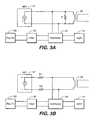
- FIGS. 4A and 4Bare schematic diagrams of the communication system of the second embodiment of the present invention having NET attenuation provided by an adjustable replication transmitter and a low pass filter arranged between the replication transmitter and the subtraction circuit.
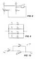
- FIG. 5is a schematic diagram of an example of an adjustable transmitter.
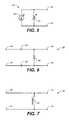
- FIG. 6is a schematic diagram of an example of a high pass filter.
- FIG. 7is a schematic diagram of another example of a high pass filter.
- FIG. 8is a schematic diagram of an example of a calibration circuit in accordance with the present invention.
- FIG. 9is a schematic of an example of a variable resistance used in the calibration circuit of FIG. 8 .
- FIG. 10is a schematic a diagram of an example of a voltage multiplier circuit.
- FIGS. 11A and 11Bare schematic diagrams of the communication system of a third embodiment of the present invention having NET noise attenuation provided by an adjustable replication transmitter.
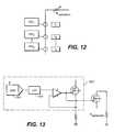
- FIG. 12is a diagram of another example of an adjustable transmitter.
- FIG. 13is a schematic diagram of one of the power digital to analog converters of FIG. 12 .
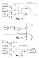
- FIG. 14is a diagram of a further example of an adjustable transmitter.
- FIG. 15is a schematic diagram of one of the power digital to analog converters of FIG. 14 .
- FIG. 16is a diagram of an additional example of an adjustable transmitter.
- FIGS. 3A-16for a description of the preferred embodiments of this invention.
- FIGS. 3A and 3BA first embodiment of the communication system of this invention is shown in FIGS. 3A and 3B .
- the present inventionis preferably implemented in an Ethernet transceiver operating at 1000 Mbits/sec.
- near end transmitter 12feeds the primary of an isolation transformer 20 .
- the secondary of the isolation transformer 20is connected to a twisted wire pair 22 , which is connected to a far end circuit, not shown.
- the primary of the isolation transformer 20is also fed to subtraction circuit 24 , and an output of subtraction circuit 24 is input to near end receiver 14 .
- a replication transmitter 130is provided to compensate for the effects of near end transmitter 12 as another input to subtraction circuit 24 .
- a high pass filter 32is further provided between replication transmitter 30 and subtraction circuit 24 . The high pass filter compensates for the decreased load seen by the near end transmitter 12 at lower frequencies.
- FIGS. 6 and 7show two circuits for realizing the high pass filter 32 .
- the circuit of FIG. 6shows an RC network having a first capacitor 60 connected between the first input 40 and first output 42 , a second capacitor 62 connected between the second input 41 and second output 43 , and a resistor 64 connected between the first output 42 and the second output 43 .
- the filter of FIG. 6reduces the amount of the voltages from the replication transmitter 130 reaching the subtraction network at lower frequencies.
- the circuit of FIG. 7illustrates a high pass filter implemented as an inductor 70 .
- the inductor 70places a load which decreases at decreasing frequencies between the first output and second output of the replication transmitter which reduces the amount of the voltages from the replication transmitter reaching the subtraction network at lower frequencies.
- the circuit of FIG. 7has the added advantage that the inductor 70 can be chosen to match the inductance of the primary of the isolation transformer seen by the outputs of the near end transmitter.
- the inductorwill simulate the DC wander behavior of NET 12 .
- inductor 70can be implemented by isolation transformer having the same characteristics of isolation transformer 20 . However, this implementation is somewhat more costly than the matching inductor.
- any DC components of the transmit signalexists in the replica path signal.
- DSPdigital signal processor
- FIGS. 4A and 4BA second embodiment of the communication method of this invention is shown in FIGS. 4A and 4B .
- the second embodimentis similar to the first embodiment and replication transmitter 30 comprises an adjustable gain control to maximize the amplitude matching between the main signal path and the replica signal path.
- FIGS. 11A and 11Billustrate a third embodiment which is similar to the second embodiment, except that the high pass filter is omitted.
- the near end transmitter 12may generate a near end signal by generating a plurality of near end currents and summing the plurality of near end currents.
- FIG. 5A circuit which can be used to realize adjustable replication transmitter 30 is shown in FIG. 5 .
- the replication transmittercomprises a current source 50 , connected in parallel with a load 52 .
- Either current source 50 , load or resistor 52 , or bothcan be varied to produce the adjustable voltages at the output thereof.
- FIG. 8illustrates an example of a circuit to adjust or calibrate resistor R 52 to match output resistor R.
- one way to adjust the output of replication transmitter 30 to match the output NET 12is to calibrate R replication 52 such that R replication 52 is substantial equal to R. This can be accomplished by providing an external resistor R ext which has the same value as the output resistor R.
- the voltage developed across R extis compared to R replication by comparator 65 .
- R replicationis adjusted until the voltages across R ext and R replication are substantially equal.
- FIG. 9illustrates an example of an adjustable or variable resistance comprising n switchable resistances R r1 through R m which are switched by respective switches S 1 through S n , in response to comparator 65 .
- the calibration or adjustment of R replicationcan be conducted upon startup, continuously, on a timed basis or upon a manual request.
- FIG. 9illustrates another arrangement in which the output voltage of replication transmitter is adjusted by voltage multiplier 200 .
- V′ repV rep *R F2 /R F1 .
- the output of comparator 65is used to adjust or calibrate either one or both of R F2 and R F1 .
- R F2 and R F1can be implemented, for example, as shown in FIG. 9 .
- FIG. 12is another implementation of replication transmitter 30 .
- FIG. 12illustrates a transmitter comprising n direct drive programmable high speed power digital-to-analog converters 400 1 ⁇ 400 n .
- a complete description of suchis provided in commonly assigned, copending application “Direct Drive Programmable High Speed Power Digital-to-Analog Converter,” filed Dec. 18, 2000, and assigned U.S. application Ser. No. 09/737,474 (now U.S. Pat. No. 6,462,688), the contents of which are incorporated by reference herein.
- the transmitterprovides 17 different levels which is accomplished by superpositioning selected ones of the direct drive programmable high speed power digital to analog converters 400 1 ⁇ 400 n .
- the replication transmittercomprises current sources I 1 . . . I n configured in series to develop an output voltage across R replication .
- R replicationmay be adjustable similarly as described above.
- R replicationmay be fixed and the output voltage may be multiplied by a voltage multiplier similar to that of voltage multiplier 200 .
- FIG. 13shows the details of one of the direct drive programmable high speed power digital-to-analog converters 400 1 and a detailed explanation of which can be found in the aforementioned commonly-assigned application.
- FIGS. 14 and 15show another embodiment which is a simplification to that in FIGS. 11 and 12 .
- the inventorhas observed that a replication voltage for each DAC is developed across each resistor R k . Accordingly, the voltages developed can be summed by summing circuit 700 . It is noted that resistor R f is adjustable as in the previous embodiments.
- FIG. 16illustrates a variant to FIG. 15 , where instead of calibrating feedback resistor R k , the output voltage is multiplied by multiplier 200 as described above.
- Adjustable replication transmittermay include an adaptive circuit for adjusting the capacitive loading to maximize the signal delay matching between the main signal path and the replica signal path.
Landscapes
- Engineering & Computer Science (AREA)
- Theoretical Computer Science (AREA)
- Cable Transmission Systems, Equalization Of Radio And Reduction Of Echo (AREA)
Abstract
Description
This application is a divisional of U.S. application Ser. No. 09/737,743, filed Dec. 18, 2000, which claims priority under 35 U.S.C. §119(e) to U.S. Provisional Application Ser. No. 60/206,409, entitled “Active Replica Transformer Hybrid,” filed May 23, 2000, and to U.S. Provisional Application Ser. No. 60/211,571, entitled “Active Replica Transformer Hybrid,” filed Jun. 15, 2000, the entire contents of each of which are incorporated by reference herein.
This application is related to the following commonly-assigned application: “Direct Drive Programmable High Speed Power Digital-to-Analog Converter,” filed Dec. 18, 2000, and assigned U.S. application Ser. No. 09/737,474 (now U.S. Pat. No. 6,462,688), the entire contents of which are incorporated by reference herein.
1. Field of the Invention
This invention relates to an active replication transmitter circuit for near end transmission cancellation and more specifically to an adjustable replication transmitter circuit with a low pass filter.
2. Background Information
Hybrids are widely used in communication systems that send and receive signals on a single pair of wires. In order to detect the signals with error free performance, it is important that near end transmission from the nearby-transmitted signal be removed from the received signal. A good hybrid is defined as a hybrid that can reject most of the near end transmission signal from the desired received signal. A good hybrid is important, because as the distance between two ends of a communicating/network nodes increases, the received signal strength decreases, while near end transmission signal from the nearby transmitted signal stays approximately constant. In order to detect the received signal with error free performance, it is important that any near end transmission signal from the nearby transmitted signal is removed from the received signal.
In many conventional communications systems, such as PC modems, ADSL, VDSL and the like, operating on standard twisted pair telephone wires, the two ends of the communicating nodes are isolated by one or more isolation transformers. There are two types of conventional hybrids typically used in such applications. The first is a bridge hybrid, also referred to as a resistive bridge hybrid. The second type is a hybrid transformer. For these types of applications, these hybrids generally work well, because these applications do not usually utilize the low frequency range of the communications bandwidth. Another term for this is DC free signaling.
Newer communication systems, such as gigabit Ethernet (I.E.E.E. standard 802.3ab), use a non-DC free signaling. Unfortunately, conventional hybrids only work well for rejecting higher frequency near end transmission signals. Therefore, extremely complicated digital signal processing (DSP) based echo canceling technology is needed to reject not only the residual high frequency echo but also the large amplitude low frequency echo signal. This low frequency echo signal is seen by the receiver as transmitter base line wander.
U.S. Pat. No. 4,935,919 to Hiraguchi is directed to an echo canceler in a modem, which cancels echoes from hybrid transformers on both the near end and the far end. The echo canceler has a variable delay, which may be adjusted to conform to a round trip of an echo. An adaptive filter has a number of delay circuits, each adding an increment of delay. A number of these delay circuits are selected in order to provide a selected delay time.
U.S. Pat. No. 5,305,379 to Takeuchi, et al. describes a sending data buffer for holding sending data temporarily and transmitting the data to an echo canceler section. The data buffer is installed between a sending section and an echo canceler that is included in a subscriber line circuit of an integrated service digital network. The sending data buffer is operated in a shift register mode during a sending training mode, and operated in FIFO (first in-first out) mode during a sending/receiving training mode.
This invention solves these problems by using a circuit with an adjustable replication transmitter and a high pass filter to provide cross talk attenuation over a wide frequency range. The adjustable replication transmitter is adjusted so that the amplitude of the voltages at the replication transmitter provides the best possible cross talk attenuation. The high pass filter compensates for the reduced load seen by the near end transmitter at very low frequencies in order to provide effective cross talk attenuation to very low frequencies. The adjustable replication transmitter and the high pass filter can be used separately or together.
According to a first aspect of the present invention, a communication circuit comprises a near end transmitter, a hybrid having an input in communication with an output of the near end transmitter, a near end replication transmitter, a high pass filter responsive to the near end replication transmitter, a subtractor to subtract an output from the high pass filter from the output from the near end transmitter and an output of the hybrid, and a near end receiver responsive to an output of the subtractor.
According to a second aspect of the present invention, the hybrid comprises an isolation transformer.
According to a third aspect of the present invention, the hybrid comprises an active circuit.
According to a fourth aspect of the present invention, the near end replication transmitter is adjustable.
According to a fifth aspect of the present invention, the near end replication transmitter comprises a current generator connected in parallel with an adjustable load.
According to a sixth aspect of the present invention, the near end replication transmitter comprises an adjustable current generator connected in parallel with a load.
According to a seventh aspect of the present invention, an adjustable capacitive load is provided in communication with the near end replication transmitter to maximize signal delay matching between the near end transmitter and the near end replication transmitter.
According to an eighth aspect of the present invention, an adaptive control circuit is provided and is responsive to the adaptive control circuit.
According to a ninth aspect of the present invention, the high pass filter comprises an inductor having similar characteristics as the hybrid.
According to a tenth aspect of the present invention, the high pass filter comprises a combination of a resistance and a capacitance.
According to an eleventh aspect of the present invention, a communication circuit comprises a near end transmitter, a hybrid having an input in communication with an output of the near end transmitter, a near end adjustable replication transmitter, a subtractor to subtract an output from the near end adjustable replication transmitter from the output from the near end transmitter and the hybrid, and a near end receiver responsive to an output of the subtractor.
According to a twelfth aspect of the present invention, a communication circuit comprises near end transmitting means for transmitting a transmitted signal, hybrid means having an input in communication with an output of the near end transmitting means for communicating the transmitted signal to and a received signal from a channel, near end replication transmitting means for generating a replication signal, high pass filter means for high pass filtering the replication signal, subtracting means for the high pass filtered replication signal from the transmitted and received signals, and near end receiving means for receiving an output signal from the subtracting means.
According to a thirteenth aspect of the present invention, a communication circuit comprises near end transmitting means for transmitting a transmitted signal, hybrid means having an input in communication with an output of the near end transmitting means for communicating the transmitted signal to and a received signal from a channel, near end adjustable replication transmitting means for generating an adjustable replication signal, subtracting means for subtracting the adjustable replication signal from the received signal and the transmitted signal, and near end receiving means for receiving an output of the subtracting means.
According to a fourteenth aspect of the present invention, a communication method comprises the steps of (a) transmitting a transmitted signal, (b) combining the transmitted signal with a received signal from a channel, (c) generating a replication signal, (d) high pass filtering the replication signal, (e) subtracting the high pass filtered replication signal from the transmitted and received signals, and (f) receiving an output signal from step (e).
According to a fifteenth aspect of the present invention, a communication method comprises the steps of (a) transmitting a transmitted signal, (b) combining the transmitted signal with a received signal from a channel, (c) generating a replication signal, (d) adjusting the replication signal, (e) subtracting adjusted replication signal from the transmitted and received signals, and (f) receiving an output signal from step (e).
According to a sixteenth aspect of the present invention, a communication circuit comprises a near end circuit and a far end circuit. The near end circuit comprises a near end transmitter, a near end hybrid having a first terminal in communication with an output of the near end transmitter and a second terminal, a near end replication transmitter, a near end high pass filter responsive to the near end replication transmitter, a near end subtractor to subtract an output from the near end high pass filter from the output from the near end transmitter and the near end hybrid, and a near end receiver responsive to an output of the near end subtractor. The far end circuit comprises a far end transmitter, a far end hybrid having a third terminal in communication with an output of the far end transmitter and a fourth terminal in communication with the second terminal of the near end hybrid, a far end replication transmitter, a far end high pass filter responsive to the far end replication transmitter, a far end subtractor to subtract an output from the far end high pass filter from the output from the far end transmitter and the far end hybrid, and a far end receiver responsive to an output of the far end subtractor.
According to a seventeenth aspect of the present invention, a communication circuit comprises a near end circuit and a far end circuit. The near end circuit comprises a near end transmitter, a near end hybrid having a first terminal in communication with an output of the near end transmitter and a second terminal, a near end adjustable replication transmitter, a near end subtractor to subtract an output from the near end adjustable replication transmitter from the output from the near end transmitter and the near end hybrid, and a near end receiver responsive to an output of the near end subtractor. The far end circuit comprises a far end transmitter, a far end hybrid having a third terminal in communication with an output of the far end transmitter and fourth terminal in communication with the second terminal of the near end hybrid, a far end adjustable replication transmitter, a far end subtractor to subtract an output from the far end adjustable replication transmitter from the output from the far end transmitter and the far end hybrid, and a far end receiver responsive to an output of the far end subtractor.
According to an eighteenth aspect of the present invention, a communication circuit comprises a near end communication means and a far end communication means. The near end communication means comprises near end transmitting means for transmitting a first signal, near end hybrid means having a first terminal in communication with an output of the near end transmitting means for communicating the first signal to and in communication with a second signal from a channel, near end replication transmitting means for transmitting a near end replication signal, near end high pass filter means for high pass filtering the near end replication signal, near end subtracting means for subtracting the near end high pass filtered replication signal from the first signal from the near end transmitting means and the second signal from the near end hybrid means, and near end receiving means for receiving an output signal from the near end subtracting means. The far end communication means comprises far end transmitting means for transmitting the second signal, far end hybrid means having a second terminal in communication with an output of the far end transmitting means for communicating the second signal to and the first signal from the channel, far end replication transmitting means for generating a far end replication signal, far end high pass filter means for high pass filtering the far end replication signal, subtracting means for the far end high pass filtered replication signal from the second signal from the far end transmitting means and the first signal from the far end hybrid means, and far end receiving means for receiving an output signal from the subtracting means.
According to a nineteenth aspect of the present invention, a communication circuit comprises a near end communication means and a far end communication means. The near end communication means comprises near end transmitting means for transmitting a first signal, near end hybrid means having an input in communication with an output of the near end transmitting means for communicating the first signal to and a second signal from a channel, near end adjustable replication transmitting means for generating a near end adjustable replication signal, near end subtracting means for subtracting the near end adjustable replication signal from the first signal from the near end transmitting means and the second signal from the near end hybrid means, and near end receiving means for receiving an output of the near end subtracting means. The far end communication means comprises far end transmitting means for transmitting the second signal, far end hybrid means having an input in communication with an output of the far end transmitting means for communicating the second signal to and the first signal from the channel, far end adjustable replication transmitting means for generating a far end adjustable replication signal, far end subtracting means for subtracting the far end adjustable replication signal from the second signal from the far end transmitting means and the first signal from the far end hybrid means, and far end receiving means for receiving an output of the far end subtracting means.
According to a twentieth aspect of the present invention, a communication method comprises the steps of (a) transmitting a first signal, (b) combining the first signal with a second signal from a channel, (c) generating a first replication signal, (d) high pass filtering the first replication signal, (e) subtracting the high pass filtered first replication signal from the first and second signals, receiving an output signal from step (e), (g) transmitting the second signal, (h) combining the second signal with the first signal from the channel, (i) generating a second replication signal, (j) high pass filtering the second replication signal, (k) subtracting the high pass filtered second replication signal from the first and second signals, and receiving an output signal from step (k).
According to a twenty-first aspect of the present invention, a communication method comprises the steps of (a) transmitting a first signal, (b) combining the first signal with a second signal from a channel, (c) generating a first replication signal, (d) adjusting the first replication signal, (e) subtracting the adjusted first replication signal from the first and second signals, receiving an output signal from step (e), (g) transmitting the second signal, (h) combining the second signal with the first signal from the channel, (i) generating a second replication signal, (j) adjusting the second replication signal, (k) subtracting the adjusted second replication signal from the first and second signals, and (l) receiving an output signal from step (k).
Other objects and advantages of the present invention will become apparent to those skilled in the art upon reading the following detailed description of preferred embodiments, in conjunction with the accompanying drawings, wherein like reference numerals have been used to designate like elements, and wherein:
Refer now toFIGS. 3A-16 for a description of the preferred embodiments of this invention.
A first embodiment of the communication system of this invention is shown inFIGS. 3A and 3B . The present invention is preferably implemented in an Ethernet transceiver operating at 1000 Mbits/sec. As shown therein, nearend transmitter 12 feeds the primary of anisolation transformer 20. The secondary of theisolation transformer 20 is connected to atwisted wire pair 22, which is connected to a far end circuit, not shown. The primary of theisolation transformer 20 is also fed tosubtraction circuit 24, and an output ofsubtraction circuit 24 is input tonear end receiver 14. In this embodiment, areplication transmitter 130 is provided to compensate for the effects ofnear end transmitter 12 as another input tosubtraction circuit 24. Ahigh pass filter 32 is further provided betweenreplication transmitter 30 andsubtraction circuit 24. The high pass filter compensates for the decreased load seen by thenear end transmitter 12 at lower frequencies.
The circuit ofFIG. 7 illustrates a high pass filter implemented as aninductor 70. Theinductor 70 places a load which decreases at decreasing frequencies between the first output and second output of the replication transmitter which reduces the amount of the voltages from the replication transmitter reaching the subtraction network at lower frequencies. The circuit ofFIG. 7 has the added advantage that theinductor 70 can be chosen to match the inductance of the primary of the isolation transformer seen by the outputs of the near end transmitter. The inductor will simulate the DC wander behavior ofNET 12. Alternatively,inductor 70 can be implemented by isolation transformer having the same characteristics ofisolation transformer 20. However, this implementation is somewhat more costly than the matching inductor.
In such an arrangement, any DC components of the transmit signal exists in the replica path signal. By using this replica, a much simpler digital signal processor (DSP) based echo canceler may be employed to cancel any residual echo that is not cancelled.
A second embodiment of the communication method of this invention is shown inFIGS. 4A and 4B . The second embodiment is similar to the first embodiment andreplication transmitter 30 comprises an adjustable gain control to maximize the amplitude matching between the main signal path and the replica signal path.
A circuit which can be used to realizeadjustable replication transmitter 30 is shown inFIG. 5 . The replication transmitter comprises acurrent source 50, connected in parallel with aload 52. Eithercurrent source 50, load orresistor 52, or both can be varied to produce the adjustable voltages at the output thereof.
As a further variation to the preceding embodiments, it is proposed to provide an adjustable capacitive loading in the replica signal path to maximize the signal delay matching between the main signal path and the replica signal path. The main signal path does not see any changes as a result of adjustingreplication transmitter 30, sincereplication transmitter 30 is not connected to the main signal path.
Adjustable replication transmitter may include an adaptive circuit for adjusting the capacitive loading to maximize the signal delay matching between the main signal path and the replica signal path.
While the invention has been particularly shown and described with reference to the preferred embodiments thereof, it will be understood by those skilled in the art that various changes in form and details may be made without departing from the spirit and scope of the invention. It is well within the scope of one of ordinary skill in the art to implement any of the functional circuits described herein. More specifically while the hybrid of the present embodiment is illustrated as an isolation transformer; one skilled in the art would appreciate an active circuit being substituted for the isolation transformer.
Claims (30)
1. A communication circuit comprising:
a near end transmitter;
a hybrid having an input in communication with an output of the near end transmitter;
a near end adjustable load replication transmitter having an adjustable load;
a subtractor configured to subtract an output from the near end adjustable load replication transmitter from the output from the near end transmitter and the hybrid;
a near end receiver responsive to an output of the subtractor; and
a calibration circuit configured to adjust the adjustable load against a reference load.
2. The communication circuit ofclaim 1 , wherein the near end adjustable load replication transmitter comprises a current generator in communication with the adjustable load.
3. The communication circuit ofclaim 1 , wherein the near end adjustable load replication transmitter comprises an adjustable current generator in communication with a load.
4. The communication circuit ofclaim 1 , wherein the near end adjustable load replication transmitter is configured to maximize amplitude matching between the near end transmitter and the near end adjustable replication transmitter.
5. The communication circuit ofclaim 1 , wherein the near end adjustable load replication transmitter comprises a voltage multiplier.
6. The communication circuit ofclaim 1 , comprising:
an adjustable capacitive load in communication with the near end adjustable load replication transmitter and configured to maximize signal delay matching between the near end transmitter and the near end adjustable load replication transmitter.
7. A communication circuit comprising:
a near end transmitter;
a hybrid having an input in communication with an output of the near end transmitter;
a near end adjustable load replication transmitter having an adjustable load;
a subtractor configured to subtract an output from the near end adjustable load replication transmitter from the output from the near end transmitter and the hybrid;
a near end receiver responsive to an output of the subtractor; and
an adjustable capacitive load in communication with the near end adjustable load replication transmitter, wherein the adjustable capacitive load adjusts signal delays of transmitted and replication signals generated by the near end transmitter and the near end adjustable load replication transmitter, respectively.
8. The communication circuit ofclaim 7 , comprising:
an adaptive control circuit,
wherein the adjustable capacitive load is responsive to the adaptive control circuit.
9. A communication method, comprising the steps of:
(a) transmitting a transmitted signal;
(b) combining the transmitted signal with a received signal from a channel;
(c) generating a replication signal using a near end adjustable load replication transmitter having an adjustable load that is adjusted against a reference load;
(d) adjusting the replication signal;
(e) subtracting the adjusted replication signal from the transmitted and received signals to generate an output signal; and
(f) receiving the output signal from step (e).
10. The communication method ofclaim 9 , wherein step (d) comprises the steps of:
(d1) adjusting a current; and
(d2) adjusting the adjustable load.
11. The communication method ofclaim 9 , wherein step (d) comprises the step of:
(d1) adjusting a current.
12. The communication method ofclaim 9 , wherein step (d) comprises the step of:
(d1) maximizing amplitude matching between the replication signal and the transmitted signal.
13. A communication circuit, comprising:
a near end circuit comprising:
a near end transmitter;
a near end hybrid having a first terminal in communication with an output of the near end transmitter and a second terminal;
a near end adjustable load replication transmitter having an adjustable load;
a near end subtractor configured to subtract an output from the near end adjustable load replication transmitter from the output from the near end transmitter and the near end hybrid; and
a near end receiver responsive to an output of the near end subtractor; and
a calibration circuit configured to adjust the adjustable load against a reference load; and
a far end circuit comprising:
a far end transmitter;
a far end hybrid having a third terminal in communication with an output of the far end transmitter and a fourth terminal in communication with the second terminal of the near end hybrid;
a far end adjustable load replication transmitter having an adjustable load;
a far end subtractor configured to subtract an output from the far end adjustable load replication transmitter from the output from the far end transmitter and the far end hybrid; and
a far end receiver responsive to an output of the far end subtractor; and
a calibration circuit configured to adjust the adjustable load against a reference load.
14. A communication method, comprising the steps of:
(a) transmitting a first signal;
(b) combining the first signal with a second signal from a channel;
(c) generating a first replication signal using a first near end adjustable load replication transmitter having an adjustable load that is adjusted against a reference load;
(d) adjusting the first replication signal;
(e) subtracting the adjusted first replication signal from the first and second signals to generate a first output signal;
(f) receiving the first output signal from step (e);
(g) transmitting the second signal;
(h) combining the second signal with the first signal from the channel;
(i) generating a second replication signal using a second near end adjustable load replication transmitter having an adjustable load that is adjusted against a reference load;
(j) adjusting the second replication signal;
(k) subtracting the adjusted second replication signal from the first and second signals to generate a second output signal; and
(l) receiving the second output signal from step (k).
15. A communication circuit, comprising:
a near end transmitter comprising at least one near end current source; and
a near end replication transmitter comprising:
at least one replication current source arranged in series and configured to generate a replication voltage across a replication resistance,
wherein the at least one replication current source corresponds to a respective one of the at least one near end current source, and
wherein the at least one replication current source is in electrical communication with a respective one of the at least one near end current source; and
wherein each of the at least one near end current source comprises:
a near end transistor, and
wherein each of the at least one replication current source comprises:
a replication current transistor,
wherein a gate of a corresponding near end transistor is coupled directly to a gate of a respective near end replication transistor.
16. The communication circuit ofclaim 15 , wherein the replication voltage is scaled in accordance with a size of the replication resistance and a size of the at least one replication current transistor.
17. The communication circuit ofclaim 15 , comprising:
a hybrid having an input in communication with an output of the near end transmitter;
a subtractor configured to subtract an output from the near end replication transmitter from the output from the near end transmitter and an output of the hybrid; and
a near end receiver responsive to an output of the subtractor.
18. The communication circuit ofclaim 17 , wherein the hybrid comprises:
an output resistance; and
a transformer.
19. An Ethernet transceiver, comprising:
a near end transmitter comprising at least one near end current source; and
a near end replication transmitter comprising:
at least one replication current source arranged in series and configured to generate a replication voltage across a replication resistance,
wherein the at least one replication current source corresponds to a respective one of the at least one near end current source, and
wherein the at least one replication current source is in electrical communication with a respective one of the at least one near end current source; and
wherein each of the at least one near end current source comprises:
a near end transistor, and
wherein each of the at least one replication current source comprises:
a replication current transistor,
wherein a gate of a corresponding near end transistor is coupled directly to a gate of a respective near end replication transistor.
20. The Ethernet transceiver ofclaim 19 , wherein the replication voltage is scaled in accordance with a size of the replication resistance and a size of the at least one replication current transistor.
21. The Ethernet transceiver ofclaim 19 , comprising:
a hybrid having an input in communication with an output of the near end transmitter;
a subtractor configured to subtract an output from the near end replication transmitter from the output from the near end transmitter and an output of the hybrid; and
a near end receiver responsive to an output of the subtractor.
22. The Ethernet transceiver ofclaim 21 , wherein the hybrid comprises:
an output resistance; and
a transformer.
23. The Ethernet transceiver ofclaim 21 , wherein the Ethernet transceiver is compliant with I.E.E.E. 802.3ab.
24. A transceiving method, comprising the steps of:
(a) generating a near end signal for transmission via a transceiver by:
(a1) generating a plurality of near end currents; and
(a2) summing the generated plurality of near end currents generated in step (a1); and
(b) generating a replication signal by:
(b1) generating a plurality of replication currents based on the generated plurality of near end currents generated in step (a1); and
(b2) summing the generated plurality of replication currents generated in step (b1).
25. The transceiving method ofclaim 24 , wherein step (b) comprises the step of:
(b3) converting the summed replication currents summed in step (b2) to a voltage.
26. The transceiving method ofclaim 24 , comprising the steps of:
(c) combining a received signal with the near end signal generated in step (a);
(d) subtracting the replication signal in step (b) from the combined signal in step (c) to generate an output; and
(e) receiving the output from step (d).
27. The communication circuit ofclaim 1 , wherein the subtractor receives a transmitted signal generated by the near end transmitter directly from the output of the near end transmitter.
28. The communication circuit ofclaim 1 , wherein the near end adjustable load replication transmitter replicates an amplitude of a transmitted signal generated by the near end transmitter.
29. The communication method ofclaim 9 , wherein step (d) comprises the step of:
(d1) replicating an amplitude of the transmitted signal.
30. A communication method comprising:
(a) transmitting a transmitted signal;
(b) combining the transmitted signal with a received signal from a channel;
(c) generating a replication signal using a near end adjustable load replication transmitter having an adjustable load;
(d) adjusting the replication signal;
(e) subtracting the adjusted replication signal from the transmitted and received signals to generate an output signal; and
(f) receiving the output signal from step (e);
wherein step (d) comprises the step of:
(d1) adjusting signal delays of the transmitted signal and the replication signal.
Priority Applications (1)
| Application Number | Priority Date | Filing Date | Title |
|---|---|---|---|
| US11/089,010US7804904B1 (en) | 2000-05-23 | 2005-03-24 | Active replica transformer hybrid |
Applications Claiming Priority (4)
| Application Number | Priority Date | Filing Date | Title |
|---|---|---|---|
| US20640900P | 2000-05-23 | 2000-05-23 | |
| US21157100P | 2000-06-15 | 2000-06-15 | |
| US09/737,743US7194037B1 (en) | 2000-05-23 | 2000-12-18 | Active replica transformer hybrid |
| US11/089,010US7804904B1 (en) | 2000-05-23 | 2005-03-24 | Active replica transformer hybrid |
Related Parent Applications (1)
| Application Number | Title | Priority Date | Filing Date |
|---|---|---|---|
| US09/737,743ContinuationUS7194037B1 (en) | 2000-05-23 | 2000-12-18 | Active replica transformer hybrid |
Publications (1)
| Publication Number | Publication Date |
|---|---|
| US7804904B1true US7804904B1 (en) | 2010-09-28 |
Family
ID=37863894
Family Applications (3)
| Application Number | Title | Priority Date | Filing Date |
|---|---|---|---|
| US09/737,743Expired - LifetimeUS7194037B1 (en) | 2000-05-23 | 2000-12-18 | Active replica transformer hybrid |
| US11/030,205Expired - LifetimeUS7729429B1 (en) | 2000-05-23 | 2005-01-07 | Active replica transformer hybrid |
| US11/089,010Expired - Fee RelatedUS7804904B1 (en) | 2000-05-23 | 2005-03-24 | Active replica transformer hybrid |
Family Applications Before (2)
| Application Number | Title | Priority Date | Filing Date |
|---|---|---|---|
| US09/737,743Expired - LifetimeUS7194037B1 (en) | 2000-05-23 | 2000-12-18 | Active replica transformer hybrid |
| US11/030,205Expired - LifetimeUS7729429B1 (en) | 2000-05-23 | 2005-01-07 | Active replica transformer hybrid |
Country Status (1)
| Country | Link |
|---|---|
| US (3) | US7194037B1 (en) |
Families Citing this family (12)
| Publication number | Priority date | Publication date | Assignee | Title |
|---|---|---|---|---|
| US7194037B1 (en)* | 2000-05-23 | 2007-03-20 | Marvell International Ltd. | Active replica transformer hybrid |
| US7433665B1 (en) | 2000-07-31 | 2008-10-07 | Marvell International Ltd. | Apparatus and method for converting single-ended signals to a differential signal, and transceiver employing same |
| US7312739B1 (en)* | 2000-05-23 | 2007-12-25 | Marvell International Ltd. | Communication driver |
| US7606547B1 (en) | 2000-07-31 | 2009-10-20 | Marvell International Ltd. | Active resistance summer for a transformer hybrid |
| US7486786B2 (en)* | 2004-09-29 | 2009-02-03 | Stmicroelectronics, Inc. | Apparatus and method for performing impedance synthesis in a transmitter |
| US7548799B2 (en)* | 2006-07-25 | 2009-06-16 | Silicon Laboratories, Inc. | Powered device including a detection signature resistor |
| US7979168B2 (en)* | 2006-07-25 | 2011-07-12 | Silicon Laboratories Inc. | Powered device including a multi-use detection resistor |
| US7814450B2 (en)* | 2006-12-31 | 2010-10-12 | Texas Instruments Incorporated | Active skew control of a digital phase-lock loop using delay lock-loops |
| US7660570B2 (en)* | 2007-03-12 | 2010-02-09 | John Mezzalingua Associates, Inc. | Active step attenuator |
| US8098768B2 (en)* | 2008-02-11 | 2012-01-17 | Aquantia Corporation | Compensation of ethernet transmit baseline wander |
| US9124282B1 (en)* | 2014-03-10 | 2015-09-01 | Analog Devices Global | Digital-to-analog converter with correction for parasitic routing resistance |
| TWI813496B (en)* | 2022-11-07 | 2023-08-21 | 瑞昱半導體股份有限公司 | Radio frequency circuit and calibration method therefor |
Citations (293)
| Publication number | Priority date | Publication date | Assignee | Title |
|---|---|---|---|---|
| US3297951A (en) | 1963-12-20 | 1967-01-10 | Ibm | Transversal filter having a tapped and an untapped delay line of equal delay, concatenated to effectively provide sub-divided delays along both lines |
| US3500215A (en) | 1965-11-16 | 1970-03-10 | Philips Corp | Filter for bivalent pulse signals |
| US3521170A (en) | 1966-03-05 | 1970-07-21 | Philips Corp | Transversal digital filters having analog to digital converter for analog signals |
| US3543009A (en) | 1966-05-13 | 1970-11-24 | Research Corp | Binary transversal filter systems |
| US3602830A (en)* | 1969-10-21 | 1971-08-31 | Honeywell Inc | A constant current control circuit |
| US3793589A (en) | 1972-06-28 | 1974-02-19 | Gen Electric | Data communication transmitter utilizing vector waveform generation |
| US3973089A (en) | 1973-10-29 | 1976-08-03 | General Electric Company | Adaptive hybrid circuit |
| US4071842A (en) | 1975-08-28 | 1978-01-31 | Bell Telephone Laboratories, Incorporated | Apparatus for analog to digital conversion |
| US4087654A (en)* | 1975-11-28 | 1978-05-02 | Bell Telephone Laboratories, Incorporated | Echo canceller for two-wire full duplex data transmission |
| US4112253A (en) | 1976-07-22 | 1978-09-05 | Siemens Aktiengesellschaft | Device for the transmission of push-pull signals across a two-wire line in full duplex operation |
| US4131767A (en) | 1976-09-07 | 1978-12-26 | Bell Telephone Laboratories, Incorporated | Echo cancellation in two-wire, two-way data transmission systems |
| US4152541A (en) | 1978-02-03 | 1979-05-01 | Burroughs Corporation | Full duplex driver/receiver |
| USRE30111E (en) | 1974-10-15 | 1979-10-09 | Motorola, Inc. | Digital single signal line full duplex method and apparatus |
| US4309673A (en) | 1980-03-10 | 1982-01-05 | Control Data Corporation | Delay lock loop modulator and demodulator |
| US4321753A (en) | 1978-09-01 | 1982-03-30 | Illinois Tool Works Inc. | Electronic gear checker |
| US4362909A (en) | 1979-05-14 | 1982-12-07 | U.S. Philips Corporation | Echo canceler with high-pass filter |
| US4393494A (en) | 1979-10-04 | 1983-07-12 | Cselt Centro Studi E Laboratori Telecomunicazioni S.P.A. | Transceiver for full-duplex transmission of digital signals over a common line |
| US4393370A (en) | 1980-04-30 | 1983-07-12 | Nippon Electric Co., Ltd. | Digital to analog converter using matrix of current sources |
| US4408190A (en) | 1980-06-03 | 1983-10-04 | Tokyo Shibaura Denki Kabushiki Kaisha | Resistorless digital-to-analog converter using cascaded current mirror circuits |
| US4464545A (en) | 1981-07-13 | 1984-08-07 | Bell Telephone Laboratories, Incorporated | Echo canceller |
| US4503421A (en) | 1981-05-27 | 1985-03-05 | Nippon Electric Co., Ltd. | Digital to analog converter |
| US4527126A (en) | 1983-08-26 | 1985-07-02 | Micro Component Technology, Inc. | AC parametric circuit having adjustable delay lock loop |
| US4535206A (en) | 1980-04-09 | 1985-08-13 | At&T Bell Laboratories | Echo cancellation in two-wire full-duplex data transmission with estimation of far-end data components |
| US4591832A (en) | 1984-07-18 | 1986-05-27 | Rca Corporation | Digital-to-analog conversion system as for use in a digital TV receiver |
| US4605826A (en) | 1982-06-23 | 1986-08-12 | Nec Corporation | Echo canceler with cascaded filter structure |
| US4621172A (en) | 1982-12-22 | 1986-11-04 | Nec Corporation | Fast convergence method and system for echo canceller |
| US4621356A (en) | 1983-07-18 | 1986-11-04 | Scipione Fred J | Communications interface for duplex transmission and reception of data and other signals over telephone lines |
| US4626803A (en) | 1985-12-30 | 1986-12-02 | General Electric Company | Apparatus for providing a carrier signal with two digital data streams I-Q modulated thereon |
| US4715064A (en) | 1984-06-22 | 1987-12-22 | Ncr Corporation | Adaptive hybrid circuit |
| US4727566A (en) | 1984-02-01 | 1988-02-23 | Telefonaktiebolaget Lm Ericsson | Method to test the function of an adaptive echo canceller |
| US4746903A (en) | 1985-12-30 | 1988-05-24 | International Business Machines Corporation | Parallel algorithmic digital to analog converter |
| US4817081A (en) | 1986-03-28 | 1989-03-28 | At&T And Philips Telecommunications B.V. | Adaptive filter for producing an echo cancellation signal in a transceiver system for duplex digital communication through one single pair of conductors |
| US4816830A (en) | 1987-09-14 | 1989-03-28 | Cooper James C | Waveform shaping apparatus and method |
| US4868571A (en) | 1986-10-21 | 1989-09-19 | Nec Corporation | Digital to analog converter |
| US4878244A (en) | 1985-09-16 | 1989-10-31 | Northern Telecom Limited | Electronic hybrid circuit |
| US4888762A (en) | 1987-02-17 | 1989-12-19 | Nec Corporation | Echo canceller for bidirectional transmission on two-wire subscriber lines |
| US4894820A (en) | 1987-03-24 | 1990-01-16 | Oki Electric Industry Co., Ltd. | Double-talk detection in an echo canceller |
| US4935919A (en) | 1986-09-16 | 1990-06-19 | Nec Corporation | Full duplex modem having two echo cancellers for a near end echo and a far end echo |
| US4947171A (en) | 1988-03-31 | 1990-08-07 | Deutsche Itt Industries Gmbh | Circuit arrangement for averaging signals during pulse-density D/A or A/D conversion |
| US4970715A (en) | 1987-03-27 | 1990-11-13 | Universal Data Systems, Inc. | Modem with improved remote echo location and cancellation |
| US4972360A (en) | 1988-08-30 | 1990-11-20 | International Business Machines Corp. | Digital filter for a modem sigma-delta analog-to-digital converter |
| US4988960A (en) | 1988-12-21 | 1991-01-29 | Yamaha Corporation | FM demodulation device and FM modulation device employing a CMOS signal delay device |
| US4993045A (en) | 1988-10-31 | 1991-02-12 | Racal Data Communications Inc. | Modem diagnostic loop |
| US4999830A (en) | 1989-09-25 | 1991-03-12 | At&T Bell Laboratories | Communication system analog-to-digital converter using echo information to improve resolution |
| US5018134A (en) | 1987-11-18 | 1991-05-21 | Hitachi, Ltd. | Method for cancelling echo in a transmitter and an apparatus therefor |
| US5043730A (en) | 1988-12-16 | 1991-08-27 | Nakamichi Corporation | Digital-analog conversion circuit with application of voltage biasing for distortion stabilization |
| US5084865A (en) | 1989-02-23 | 1992-01-28 | Nec Corporation | Echo canceller having fir and iir filters for cancelling long tail echoes |
| US5119365A (en) | 1990-12-14 | 1992-06-02 | Ag Communication Systems Corporation | Bi-directional buffer line amplifier |
| US5136260A (en) | 1991-03-08 | 1992-08-04 | Western Digital Corporation | PLL clock synthesizer using current controlled ring oscillator |
| US5148427A (en) | 1990-04-10 | 1992-09-15 | Level One Communications, Inc. | Non-linear echo canceller |
| US5153450A (en) | 1991-07-16 | 1992-10-06 | Samsung Semiconductor, Inc. | Programmable output drive circuit |
| US5164725A (en) | 1992-02-05 | 1992-11-17 | Tritech Microelectronics International Pte Ltd. | Digital to analog converter with current sources paired for canceling error sources |
| US5175764A (en) | 1990-10-18 | 1992-12-29 | Ag Communication Systems Corporation | Enhanced high voltage line interface circuit |
| US5185538A (en) | 1990-06-13 | 1993-02-09 | Mitsubishi Denki Kabushiki Kaisha | Output circuit for semiconductor integrated circuits having controllable load drive capability and operating method thereof |
| US5202528A (en) | 1990-05-14 | 1993-04-13 | Casio Computer Co., Ltd. | Electronic musical instrument with a note detector capable of detecting a plurality of notes sounded simultaneously |
| US5204880A (en) | 1991-04-23 | 1993-04-20 | Level One Communications, Inc. | Differential line driver employing predistortion |
| US5204854A (en)* | 1991-08-23 | 1993-04-20 | Sierra Semiconductor Corporation | Adaptive hybrid |
| US5212659A (en) | 1991-10-08 | 1993-05-18 | Crystal Semiconductor | Low precision finite impulse response filter for digital interpolation |
| US5222084A (en) | 1990-06-25 | 1993-06-22 | Nec Corporation | Echo canceler having adaptive digital filter unit associated with delta-sigma modulation circuit |
| US5243346A (en) | 1990-12-19 | 1993-09-07 | Nec Corporation | Digital-to-analog converting device using decoders and parallel-to-serial converters |
| US5243347A (en) | 1992-09-28 | 1993-09-07 | Motorola, Inc. | Monotonic current/resistor digital-to-analog converter and method of operation |
| US5245654A (en) | 1991-10-10 | 1993-09-14 | Cermetek Microelectronics, Inc. | Solid state isolation device using opto-isolators |
| US5245231A (en) | 1991-12-30 | 1993-09-14 | Dell Usa, L.P. | Integrated delay line |
| US5248956A (en) | 1991-04-05 | 1993-09-28 | Center For Innovative Technology | Electronically controllable resistor |
| US5253272A (en) | 1991-03-01 | 1993-10-12 | Amp Incorporated | Digital data transmission system with adaptive predistortion of transmitted pulses |
| US5253249A (en) | 1989-06-29 | 1993-10-12 | Digital Equipment Corporation | Bidirectional transceiver for high speed data system |
| US5254994A (en) | 1991-03-06 | 1993-10-19 | Kabushiki Kaisha Toshiba | Current source cell use in current segment type D and A converter |
| US5267269A (en) | 1991-09-04 | 1993-11-30 | Level One Communications, Inc. | System and method employing predetermined waveforms for transmit equalization |
| US5269313A (en) | 1991-09-09 | 1993-12-14 | Sherwood Medical Company | Filter and method for filtering baseline wander |
| US5272453A (en) | 1992-08-03 | 1993-12-21 | Motorola Inc. | Method and apparatus for switching between gain curves of a voltage controlled oscillator |
| US5280526A (en) | 1992-05-26 | 1994-01-18 | At&T Bell Laboratories | Transformer-less hybrid circuit |
| US5282157A (en) | 1990-09-13 | 1994-01-25 | Telecom Analysis Systems, Inc. | Input impedance derived from a transfer network |
| US5283582A (en) | 1991-12-20 | 1994-02-01 | Texas Instruments Incorporated | Circuitry and method for current input analog to digital conversion |
| US5305379A (en) | 1991-05-22 | 1994-04-19 | Hitachi, Ltd. | Semiconductor integrated device |
| US5307405A (en) | 1992-09-25 | 1994-04-26 | Qualcomm Incorporated | Network echo canceller |
| US5307064A (en) | 1991-09-09 | 1994-04-26 | Tekuno Esu Kabushiki Kaisha | Digital-to-analog converter capable of reducing load of low-pass filter |
| US5323157A (en) | 1993-01-15 | 1994-06-21 | Motorola, Inc. | Sigma-delta digital-to-analog converter with reduced noise |
| US5325400A (en) | 1992-06-04 | 1994-06-28 | The Lan Guys, Inc. | Method and apparatus for predistortion of signals in digital transmission systems |
| US5357145A (en) | 1992-12-22 | 1994-10-18 | National Semiconductor Corporation | Integrated waveshaping circuit using weighted current summing |
| US5367540A (en) | 1992-01-16 | 1994-11-22 | Fujitsu Limited | Transversal filter for use in a digital subscriber line transmission interface |
| US5365935A (en) | 1991-09-10 | 1994-11-22 | Ralin, Inc. | Portable, multi-channel ECG data monitor/recorder |
| US5375147A (en) | 1991-08-21 | 1994-12-20 | Fujitsu Limited | Jitter compensating device |
| US5388092A (en) | 1989-06-27 | 1995-02-07 | Nec Corporation | Echo canceller for two-wire full duplex digital data transmission |
| US5388123A (en) | 1991-05-10 | 1995-02-07 | Matsushita Electric Industrial Co., Ltd. | Data receiving system |
| US5392042A (en) | 1993-08-05 | 1995-02-21 | Martin Marietta Corporation | Sigma-delta analog-to-digital converter with filtration having controlled pole-zero locations, and apparatus therefor |
| US5399996A (en) | 1993-08-16 | 1995-03-21 | At&T Global Information Solutions Company | Circuit and method for minimizing electromagnetic emissions |
| US5418478A (en) | 1993-07-30 | 1995-05-23 | Apple Computer, Inc. | CMOS differential twisted-pair driver |
| US5440514A (en) | 1994-03-08 | 1995-08-08 | Motorola Inc. | Write control for a memory using a delay locked loop |
| US5440515A (en) | 1994-03-08 | 1995-08-08 | Motorola Inc. | Delay locked loop for detecting the phase difference of two signals having different frequencies |
| US5444739A (en) | 1991-09-12 | 1995-08-22 | Matsushita Electric Industrial Co., Ltd. | Equalizer for data receiver apparatus |
| US5465272A (en) | 1994-04-08 | 1995-11-07 | Synoptics Communications, Inc. | Data transmitter baseline wander correction circuit |
| US5471665A (en) | 1994-10-18 | 1995-11-28 | Motorola, Inc. | Differential DC offset compensation circuit |
| US5479124A (en) | 1993-08-20 | 1995-12-26 | Nexgen Microsystems | Slew rate controller for high speed bus |
| US5489873A (en) | 1994-03-03 | 1996-02-06 | Motorola, Inc. | Active low-pass filter |
| US5507036A (en) | 1994-09-30 | 1996-04-09 | Rockwell International | Apparatus with distortion cancelling feed forward signal |
| US5508656A (en) | 1993-12-23 | 1996-04-16 | Sgs-Thomson Microelectronics S.A. | Amplifier with offset correction |
| US5517435A (en) | 1993-03-11 | 1996-05-14 | Nec Corporation | Method of identifying an unknown system with a band-splitting adaptive filter and a device thereof |
| US5517141A (en) | 1993-11-05 | 1996-05-14 | Motorola, Inc. | Differential high speed track and hold amplifier |
| US5521540A (en) | 1992-03-24 | 1996-05-28 | Bull, S.A. | Method and apparatus for multi-range delay control |
| US5537113A (en) | 1992-06-17 | 1996-07-16 | Advantest Corp. | A/D or D/A conversion using distribution of differential waveforms to interleaved converters |
| US5539405A (en) | 1993-07-29 | 1996-07-23 | Cirrus Logic, Inc. | DAC achieving monotonicity with equal sources and shift array therefor |
| US5539403A (en) | 1992-06-01 | 1996-07-23 | Matsushita Electric Industrial Co, Ltd | D/A conversion apparatus and A/D conversion apparatus |
| US5539773A (en) | 1992-02-17 | 1996-07-23 | Thomson Consumer Electronics S.A. | Method and apparatus for ghost cancelling and/or equalizing |
| US5559476A (en) | 1995-05-31 | 1996-09-24 | Cirrus Logic, Inc. | Voltage controlled oscillator including voltage controlled delay circuit with power supply noise isolation |
| US5568064A (en) | 1995-01-23 | 1996-10-22 | International Business Machines Corporation | Bidirectional transmission line driver/receiver |
| US5568142A (en) | 1994-10-20 | 1996-10-22 | Massachusetts Institute Of Technology | Hybrid filter bank analog/digital converter |
| US5572158A (en) | 1994-02-15 | 1996-11-05 | Rambus, Inc. | Amplifier with active duty cycle correction |
| US5572159A (en) | 1994-11-14 | 1996-11-05 | Nexgen, Inc. | Voltage-controlled delay element with programmable delay |
| US5577027A (en) | 1995-04-18 | 1996-11-19 | Intel Corporation | Apparatus and method for effectively eliminating the echo signal of transmitting signal in a modem |
| US5579004A (en) | 1994-11-02 | 1996-11-26 | Advanced Micro Devices, Inc. | Digital interpolation circuit for a digital-to-analog converter circuit |
| US5585795A (en) | 1992-04-06 | 1996-12-17 | Fujitsu Limited | D/A converter including output buffer having a controllable offset voltage |
| US5585802A (en) | 1994-11-02 | 1996-12-17 | Advanced Micro Devices, Inc. | Multi-stage digital to analog conversion circuit and method |
| US5587681A (en) | 1993-10-29 | 1996-12-24 | Plessey Semiconductors Limited | DC restoration circuit |
| US5589788A (en) | 1994-05-12 | 1996-12-31 | Hewlett-Packard Company | Timing adjustment circuit |
| US5596439A (en) | 1995-08-01 | 1997-01-21 | Viasat, Inc. | Self-interference cancellation for two-party relayed communication |
| US5600321A (en) | 1995-06-07 | 1997-02-04 | Advanced Micro Devices Inc. | High speed, low power CMOS D/A converter for wave synthesis in network |
| US5613233A (en) | 1994-09-30 | 1997-03-18 | Rockwell International Corp. | Apparatus with distortion cancelling feedback signal |
| US5625357A (en) | 1995-02-16 | 1997-04-29 | Advanced Micro Devices, Inc. | Current steering semi-digital reconstruction filter |
| US5629652A (en) | 1996-05-09 | 1997-05-13 | Analog Devices | Band-switchable, low-noise voltage controlled oscillator (VCO) for use with low-q resonator elements |
| US5648738A (en) | 1994-11-01 | 1997-07-15 | Cirrus Logic, Inc. | Read channel having auto-zeroing and offset compensation, and power-down between servo fields |
| US5651029A (en) | 1995-05-16 | 1997-07-22 | Myson Technology, Inc. | Apparatus for transmitting an output with predetermined frequency response to an unshielded twisted-pair media and waveform shaping circuit and method employed therein |
| US5659609A (en) | 1994-09-05 | 1997-08-19 | Fujitsu Limited | Echo canceller and waveform-distortion compensation device |
| US5663728A (en) | 1995-05-18 | 1997-09-02 | Hughes Aircraft Company | Digital-to-analog converted (DAC) and method that set waveform rise and fall times to produce an analog waveform that approximates a piecewise linear waveform to reduce spectral distortion |
| US5666354A (en) | 1995-12-20 | 1997-09-09 | International Business Machines Corporation | CMOS bi-directional differential link |
| US5684482A (en) | 1996-03-06 | 1997-11-04 | Ian A. Galton | Spectral shaping of circuit errors in digital-to-analog converters |
| US5687330A (en) | 1993-06-18 | 1997-11-11 | Digital Equipment Corporation | Semiconductor process, power supply and temperature compensated system bus integrated interface architecture with precision receiver |
| US5696796A (en) | 1995-06-07 | 1997-12-09 | Comsat Corporation | Continuously variable if sampling method for digital data transmission |
| US5703541A (en) | 1995-06-05 | 1997-12-30 | Mitsubishi Denki Kabushiki Kaisha | Ring oscillator with two inverters per unit inverter circuit |
| US5719515A (en) | 1993-09-27 | 1998-02-17 | Sgs-Thomson Microelectronics S.A. | Digital delay line |
| US5726583A (en) | 1996-07-19 | 1998-03-10 | Kaplinsky; Cecil H. | Programmable dynamic line-termination circuit |
| US5745564A (en) | 1995-01-26 | 1998-04-28 | Northern Telecom Limited | Echo cancelling arrangement |
| US5757219A (en) | 1996-01-31 | 1998-05-26 | Analogic Corporation | Apparatus for and method of autozeroing the input of a charge-to-voltage converter |
| US5757298A (en) | 1996-02-29 | 1998-05-26 | Hewlett-Packard Co. | Method and apparatus for error compensation using a non-linear digital-to-analog converter |
| US5760726A (en) | 1996-08-23 | 1998-06-02 | Motorola, Inc. | Digital-to-analog converter with dynamic matching and bit splitting |
| US5790060A (en) | 1996-09-11 | 1998-08-04 | Harris Corporation | Digital-to-analog converter having enhanced current steering and associated method |
| US5796725A (en) | 1994-08-31 | 1998-08-18 | Nec Corporation | Echo canceller capable of cancelling an echo signal at a high speed |
| US5798661A (en) | 1996-02-09 | 1998-08-25 | Advanced Micro Devices, Inc. | Method for continuous waveform synthesis |
| US5798664A (en) | 1995-04-07 | 1998-08-25 | Nec Corporation | Offset cancelling amplifier circuit having Miller integrator as offset detector |
| US5812597A (en) | 1994-09-21 | 1998-09-22 | Tut Systems, Inc. | Circuit for preventing base line wander of digital signals in a network receiver |
| US5822426A (en) | 1995-06-06 | 1998-10-13 | International Business Machines Corporation | Balanced hybrid circuit |
| US5821892A (en) | 1996-11-20 | 1998-10-13 | Texas Instruments Incorporated | Digital to analog conversion system |
| US5825819A (en) | 1996-04-23 | 1998-10-20 | Motorola, Inc. | Asymmetrical digital subscriber line (ADSL) line driver circuit |
| US5834860A (en) | 1992-11-25 | 1998-11-10 | Sgs-Thomson Microelectronics Ltd. | Controlled impedance transistor switch circuit |
| US5838186A (en) | 1994-09-21 | 1998-11-17 | Mitsubishi Denki Kabushiki Kaisha | Signal output circuit with reduced noise in output signal |
| US5838177A (en) | 1997-01-06 | 1998-11-17 | Micron Technology, Inc. | Adjustable output driver circuit having parallel pull-up and pull-down elements |
| US5841809A (en) | 1996-06-03 | 1998-11-24 | Fujitsu Limimited | Access line termination unit |
| US5841386A (en) | 1996-01-18 | 1998-11-24 | Texas Instruments Incorporated | Simple high resolution monolithic DAC for the tuning of an external VCXO (voltage controlled quartz oscillator) |
| US5844439A (en) | 1996-03-13 | 1998-12-01 | Integrated Circuit Systems, Inc. | DC restoration circuit for multi-level transmission signals |
| US5859552A (en) | 1995-10-06 | 1999-01-12 | Lsi Logic Corporation | Programmable slew rate control circuit for output buffer |
| US5864587A (en) | 1995-06-06 | 1999-01-26 | Lsi Logic Corporation | Differential signal receiver |
| US5880615A (en) | 1996-12-10 | 1999-03-09 | Intel Corporation | Method and apparatus for detecting differential threshold levels while compensating for baseline wander |
| US5887059A (en) | 1996-01-30 | 1999-03-23 | Advanced Micro Devices, Inc. | System and method for performing echo cancellation in a communications network employing a mixed mode LMS adaptive balance filter |
| US5894496A (en) | 1996-09-16 | 1999-04-13 | Ericsson Inc. | Method and apparatus for detecting and compensating for undesired phase shift in a radio transceiver |
| US5898340A (en) | 1996-11-20 | 1999-04-27 | Chatterjee; Manjirnath A. | High power efficiency audio amplifier with digital audio and volume inputs |
| US5930686A (en) | 1993-05-05 | 1999-07-27 | Marconi Electronic Systems Limited | Integrated transceiver circuit packaged component |
| US5936450A (en) | 1997-03-21 | 1999-08-10 | National Semiconductor Corporation | Waveshaping circuit using digitally controlled weighted current summing |
| US5940442A (en) | 1997-01-30 | 1999-08-17 | National Semioonductor Corporation | High speed data receiver |
| US5940498A (en) | 1996-06-14 | 1999-08-17 | Siemens Aktiengesellschaft | Electronic voice circuit configuration |
| US5949362A (en) | 1997-08-22 | 1999-09-07 | Harris Corporation | Digital-to-analog converter including current cell matrix with enhanced linearity and associated methods |
| US5963069A (en) | 1995-10-16 | 1999-10-05 | Altera Corporation | System for distributing clocks using a delay lock loop in a programmable logic circuit |
| US5982317A (en) | 1997-04-18 | 1999-11-09 | Jesper Steensgaard-Madsen | Oversampled digital-to-analog converter based on nonlinear separation and linear recombination |
| US5999044A (en) | 1998-04-13 | 1999-12-07 | Credence Systems Corporation | Differential driver having multiple output voltage ranges |
| EP0800278B1 (en) | 1996-04-04 | 1999-12-08 | Mitel Semiconductor Limited | An error correction circuit |
| US6005370A (en) | 1998-01-26 | 1999-12-21 | Physio-Control Manufacturing Corporation | Automatic rate control for defibrillator capacitor charging |
| US6014048A (en) | 1998-05-27 | 2000-01-11 | Advanced Micro Devices, Inc. | Clock generator with multiple feedback paths including a delay locked loop path |
| US6037812A (en) | 1998-05-18 | 2000-03-14 | National Semiconductor Corporation | Delay locked loop (DLL) based clock synthesis |
| US6038266A (en) | 1998-09-30 | 2000-03-14 | Lucent Technologies, Inc. | Mixed mode adaptive analog receive architecture for data communications |
| US6043766A (en) | 1997-12-10 | 2000-03-28 | National Semiconductor Corporation | Distributive encoder for encoding error signals which represent signal peak errors in data signals for identifying erroneous signal baseline, peak and equalization conditions |
| US6044489A (en) | 1997-12-10 | 2000-03-28 | National Semiconductor Corporation | Data signal baseline error detector |
| US6047346A (en) | 1998-02-02 | 2000-04-04 | Rambus Inc. | System for adjusting slew rate on an output of a drive circuit by enabling a plurality of pre-drivers and a plurality of output drivers |
| US6046607A (en) | 1994-11-21 | 2000-04-04 | Yamaha Corporation | Logic circuit controlled by a plurality of clock signals |
| US6049706A (en) | 1998-10-21 | 2000-04-11 | Parkervision, Inc. | Integrated frequency translation and selectivity |
| US6052076A (en) | 1998-10-14 | 2000-04-18 | Western Digital Corporation | Digital-to-analog converter having high resolution and high bandwidth |
| US6057716A (en) | 1998-04-07 | 2000-05-02 | Credence Systems Corporation | Inhibitable continuously-terminated differential drive circuit for an integrated circuit tester |
| WO2000028691A2 (en) | 1998-11-09 | 2000-05-18 | Broadcom Corporation, Et Al. | Multi-pair gigabit ethernet transceiver |
| WO2000028663A2 (en) | 1998-11-09 | 2000-05-18 | Broadcom Corporation | Fir filter structure with low latency for gigabit ethernet applications |
| US6067327A (en) | 1997-09-18 | 2000-05-23 | International Business Machines Corporation | Data transmitter and method therefor |
| US6087968A (en) | 1997-04-16 | 2000-07-11 | U.S. Philips Corporation | Analog to digital converter comprising an asynchronous sigma delta modulator and decimating digital filter |
| US6094082A (en) | 1998-05-18 | 2000-07-25 | National Semiconductor Corporation | DLL calibrated switched current delay interpolator |
| US6100830A (en) | 1998-01-08 | 2000-08-08 | Fujitsu Microelectronics Europe Gmbh | Differential switching circuitry |
| US6121831A (en) | 1999-05-12 | 2000-09-19 | Level One Communications, Inc. | Apparatus and method for removing offset in a gain circuit |
| US6137328A (en) | 1998-05-29 | 2000-10-24 | Hyundai Electronics Industries Co., Ltd. | Clock phase correction circuit |
| US6140857A (en) | 1999-03-29 | 2000-10-31 | Intel Corporation | Method and apparatus for reducing baseline wander |
| US6148025A (en) | 1998-04-17 | 2000-11-14 | Lucent Technologies, Inc. | System and method for compensating for baseline wander |
| US6150856A (en) | 1999-04-30 | 2000-11-21 | Micron Technology, Inc. | Delay lock loops, signal locking methods and methods of implementing delay lock loops |
| US6154784A (en) | 1998-06-10 | 2000-11-28 | Lsi Logic Corporation | Current mode ethernet transmitter |
| US6163579A (en) | 1998-03-04 | 2000-12-19 | Analog Devices, Inc. | Broadband modem transformer hybird |
| US6163283A (en) | 1998-01-08 | 2000-12-19 | Fujitsu Microelectronics Europe Gmbh | Thermometer coding circuitry |
| US6163289A (en) | 1997-09-23 | 2000-12-19 | Philips Electronics North America Corp. | Differential voltage digital-to-analog converter |
| US6166572A (en) | 1997-06-13 | 2000-12-26 | Oki Electric Industry Co., Ltd. | Voltage-controlled delay line, direct phase controlled voltage-controlled oscillator, clock/data recovery circuit, and clock/data recovery apparatus |
| US6172634B1 (en) | 1998-02-25 | 2001-01-09 | Lucent Technologies Inc. | Methods and apparatus for providing analog-fir-based line-driver with pre-equalization |
| US6173019B1 (en) | 1997-12-10 | 2001-01-09 | National Semiconductor Corporation | Control loop for data signal baseline correction |
| US6177896B1 (en) | 1998-03-13 | 2001-01-23 | Hyundai Electronics Industries Co., Ltd. | Oversampling digital/analog converter |
| US6185263B1 (en) | 1998-11-09 | 2001-02-06 | Broadcom Corporation | Adaptively configurable class-A/class-B transmit DAC for transceiver emission and power consumption control |
| US6188282B1 (en) | 1999-10-08 | 2001-02-13 | Ericsson Inc. | Differential amplifier with reduced even order non-linearity and associated methods |
| US6191719B1 (en) | 1997-08-25 | 2001-02-20 | Broadcom Corporation | Digital to analog converter with reduced ringing |
| US6192226B1 (en) | 1998-12-21 | 2001-02-20 | Motorola, Inc. | Carrier squelch processing system and apparatus |
| US6201490B1 (en) | 1997-11-14 | 2001-03-13 | Yamaha Corporation | DA conversion apparatus to reduce transient noise upon switching of analog signals |
| US6201831B1 (en) | 1998-11-13 | 2001-03-13 | Broadcom Corporation | Demodulator for a multi-pair gigabit transceiver |
| US6201841B1 (en) | 1994-12-07 | 2001-03-13 | Fujitsu Limited | Distortion compensating device |
| US6204788B1 (en) | 1998-08-25 | 2001-03-20 | Matsushita Electric Industrial Co., Ltd. | Digital/analog conversion apparatus |
| US6211716B1 (en) | 1999-05-28 | 2001-04-03 | Kendin Communications, Inc. | Baseline wander compensation circuit and method |
| US6215429B1 (en) | 1998-02-10 | 2001-04-10 | Lucent Technologies, Inc. | Distributed gain for audio codec |
| US6223061B1 (en) | 1997-07-25 | 2001-04-24 | Cleveland Medical Devices Inc. | Apparatus for low power radio communications |
| US6236645B1 (en) | 1998-03-09 | 2001-05-22 | Broadcom Corporation | Apparatus for, and method of, reducing noise in a communications system |
| US6236346B1 (en) | 1998-01-08 | 2001-05-22 | Fujitsu Limited | Cell array circuitry |
| US6236345B1 (en) | 1998-04-24 | 2001-05-22 | U.S. Philips Corporation | Video rate D/A converter with sigma-delta modulator |
| US6249164B1 (en) | 1998-09-25 | 2001-06-19 | International Business Machines Corporation | Delay circuit arrangement for use in a DAC/driver waveform generator with phase lock rise time control |
| US6249249B1 (en) | 1998-05-14 | 2001-06-19 | Kabushiki Kaisha Toshiba | Active array antenna system |
| JP2001177409A (en) | 1999-12-16 | 2001-06-29 | Philips Japan Ltd | D/a converter |
| US6259680B1 (en) | 1997-10-01 | 2001-07-10 | Adtran, Inc. | Method and apparatus for echo cancellation |
| US6259745B1 (en) | 1998-10-30 | 2001-07-10 | Broadcom Corporation | Integrated Gigabit Ethernet transmitter architecture |
| US6259957B1 (en) | 1997-04-04 | 2001-07-10 | Cirrus Logic, Inc. | Circuits and methods for implementing audio Codecs and systems using the same |
| US6266367B1 (en) | 1998-05-28 | 2001-07-24 | 3Com Corporation | Combined echo canceller and time domain equalizer |
| US6271782B1 (en) | 1998-08-06 | 2001-08-07 | Jesper Steensgaard-Madsen | Delta-sigma A/D converter |
| US6275098B1 (en) | 1999-10-01 | 2001-08-14 | Lsi Logic Corporation | Digitally calibrated bandgap reference |
| US6289068B1 (en) | 1998-06-22 | 2001-09-11 | Xilinx, Inc. | Delay lock loop with clock phase shifter |
| US6288604B1 (en) | 1998-02-03 | 2001-09-11 | Broadcom Corporation | CMOS amplifier providing automatic offset cancellation |
| US6295012B1 (en) | 1999-08-25 | 2001-09-25 | Broadcom Corporation | CMOS DAC with high impedance differential current drivers |
| US6298046B1 (en) | 1998-08-28 | 2001-10-02 | Rc Networks | Adjustable balancing circuit for an adaptive hybrid and method of adjusting the same |
| US6307490B1 (en) | 1999-09-30 | 2001-10-23 | The Engineering Consortium, Inc. | Digital to analog converter trim apparatus and method |
| US6309077B1 (en) | 1999-01-12 | 2001-10-30 | Cornell Research Foundation Inc. | Motion amplification based sensors |
| US6313775B1 (en) | 1999-09-03 | 2001-11-06 | Nokia Mobile Phones Limited | Delta-sigma modulator with two-step quantization, and method for using two-step quantization in delta-sigma modulation |
| US20010050585A1 (en) | 2000-01-18 | 2001-12-13 | Larrie Carr | Digital delay line with synchronous control |
| US6333959B1 (en) | 2000-04-25 | 2001-12-25 | Winbond Electronics Corporation | Cross feedback latch-type bi-directional shift register in a delay lock loop circuit |
| US6339390B1 (en) | 2000-10-04 | 2002-01-15 | Scott R. Velazquez | Adaptive parallel processing analog and digital converter |
| US6340940B1 (en) | 2000-07-18 | 2002-01-22 | Cirrus Logic, Inc. | Digital to analog conversion circuits and methods utilizing single-bit delta-SIGMA modulators and multiple-bit digital to analog converters |
| US6346899B1 (en)* | 1998-12-04 | 2002-02-12 | Asahi Kasei Kabushiki Kaisha | Analog current mode D/A converter using transconductors |
| US6351229B1 (en) | 2000-09-05 | 2002-02-26 | Texas Instruments Incorporated | Density-modulated dynamic dithering circuits and method for delta-sigma converter |
| USRE37619E1 (en) | 1996-01-05 | 2002-04-02 | Analog Devices, Inc. | Skewless differential switch and DAC employing the same |
| US6369734B2 (en) | 1998-02-10 | 2002-04-09 | Intel Corporation | Method and apparatus for increasing linearity and reducing noise coupling in a digital to analog converter |
| US6370190B1 (en) | 1998-09-15 | 2002-04-09 | 3Com Technologies | Data receiver including hybrid decision feedback equalizer |
| JP3273704B2 (en) | 1994-11-09 | 2002-04-15 | 新日本製鐵株式会社 | Mold width change control method for continuous casting equipment |
| US6373908B2 (en) | 1998-11-11 | 2002-04-16 | Broadcom Corporation | Adaptive electronic transmission signal cancellation apparatus for full duplex communication |
| US6373417B1 (en) | 1999-02-23 | 2002-04-16 | Cirrus Logic, Inc. | Digital to analog converter using level and timing control signals to cancel noise |
| US6377640B2 (en) | 1997-07-31 | 2002-04-23 | Stanford Syncom, Inc. | Means and method for a synchronous network communications system |
| US6377683B1 (en) | 1998-05-29 | 2002-04-23 | 3Com Corporation | Low complexity frequency domain echo canceller for DMT transceivers |
| US6385238B1 (en) | 1997-12-03 | 2002-05-07 | Kabushiki Kaisha Toshiba | Adaptive equalization and baseline wander correction circuit |
| US6385442B1 (en) | 1998-03-04 | 2002-05-07 | Symbol Technologies, Inc. | Multiphase receiver and oscillator |
| US20020061087A1 (en) | 2000-11-21 | 2002-05-23 | Stephen Williams | Apparatus and method for acquiring phase lock timing recovery in a partial response maximum likelihood (PRML) channel |
| US6408032B1 (en) | 1998-09-30 | 2002-06-18 | Pmc-Sierra Ltd. | Transmit baseline wander correction technique |
| US6415003B1 (en) | 1998-09-11 | 2002-07-02 | National Semiconductor Corporation | Digital baseline wander correction circuit |
| US20020084857A1 (en) | 2000-10-23 | 2002-07-04 | Samsung Electronics Co., Ltd. | Delay locked loop for improving high frequency characteristics and yield |
| US6421377B1 (en) | 1998-05-13 | 2002-07-16 | Globespanvirata, Inc. | System and method for echo cancellation over asymmetric spectra |
| US6433608B1 (en) | 2001-01-02 | 2002-08-13 | Realtek Semi-Conductor Co., Ltd. | Device and method for correcting the baseline wandering of transmitting signals |
| US6441761B1 (en) | 1999-12-08 | 2002-08-27 | Texas Instruments Incorporated | High speed, high resolution digital-to-analog converter with off-line sigma delta conversion and storage |
| US6452428B1 (en) | 1999-11-23 | 2002-09-17 | Intel Corporation | Slew rate control circuit |
| US20020136321A1 (en) | 1998-10-30 | 2002-09-26 | Chan Kevin T. | Reduction of aggregate EMI emissions of multiple transmitters |
| US6462688B1 (en) | 2000-12-18 | 2002-10-08 | Marvell International, Ltd. | Direct drive programmable high speed power digital-to-analog converter |
| US6477200B1 (en) | 1998-11-09 | 2002-11-05 | Broadcom Corporation | Multi-pair gigabit ethernet transceiver |
| US6476746B2 (en) | 1999-12-08 | 2002-11-05 | Texas Instruments Incorporated | Cellular base station having a high speed, high resolution digital-to-analog converter with off-line sigma delta conversion and storage |
| US6476749B1 (en) | 1998-12-21 | 2002-11-05 | Bell Canada | High speed analog-to-digital converter and digital-to-analog converter |
| US20020181601A1 (en) | 2001-03-21 | 2002-12-05 | Chin-Wen Huang | Receiver with baseline wander correction and correction method thereof |
| US6492922B1 (en) | 2000-12-14 | 2002-12-10 | Xilinx Inc. | Anti-aliasing filter with automatic cutoff frequency adaptation |
| US6501402B2 (en) | 2001-05-09 | 2002-12-31 | Broadcom Corporation | Digital-to-analogue converter using an array of current sources |
| US6509857B1 (en) | 1999-10-25 | 2003-01-21 | Texas Instruments Incorporated | Digital-to-analog converting method and digital-to-analog converter |
| US6509854B1 (en) | 1997-03-16 | 2003-01-21 | Hitachi, Ltd. | DA conversion circuit |
| US6531973B2 (en) | 2000-09-11 | 2003-03-11 | Broadcom Corporation | Sigma-delta digital-to-analog converter |
| US6535987B1 (en) | 1998-07-31 | 2003-03-18 | Stmicroelectronics S.A. | Amplifier with a fan-out variable in time |
| US6539072B1 (en) | 1997-02-06 | 2003-03-25 | Rambus, Inc. | Delay locked loop circuitry for clock delay adjustment |
| US6556677B1 (en) | 1999-05-27 | 2003-04-29 | William Christopher Hardy | Single-ended echo cancellation system and method |
| US6563870B1 (en) | 1997-12-22 | 2003-05-13 | Infineon Technologies Ag | Nonlinear echo compensator |
| US6570931B1 (en) | 1999-12-31 | 2003-05-27 | Intel Corporation | Switched voltage adaptive slew rate control and spectrum shaping transmitter for high speed digital transmission |
| US6577114B1 (en) | 2000-07-31 | 2003-06-10 | Marvell International, Ltd. | Calibration circuit |
| US6576746B2 (en) | 1998-10-13 | 2003-06-10 | Immunomedics, Inc. | Site-specific labeling of disulfide-containing targeting vectors |
| US6583742B1 (en) | 1998-02-26 | 2003-06-24 | Wolfson Microelectronics Limited | Digital to analogue converter with dynamic element matching |
| US6608743B1 (en) | 1999-10-19 | 2003-08-19 | Nec Corporation | Delay locked loop, synchronizing method for the same and semiconductor device equipped with the same |
| US20030174660A1 (en) | 2000-06-20 | 2003-09-18 | Thomas Blon | Circuit arrangement for the analogue suppression of echos |
| US6633178B2 (en) | 2001-09-28 | 2003-10-14 | Intel Corporation | Apparatus and method for power efficient line driver |
| US20040005015A1 (en) | 1998-10-30 | 2004-01-08 | Chan Kevin T. | Method and system for a reduced emissions direct drive transmitter for unshielded twisted pair (UTP) applications |
| US6687286B1 (en) | 1999-12-17 | 2004-02-03 | Agere Systems, Inc. | Programmable transmitter circuit for coupling to an ethernet or fast ethernet |
| US6714825B1 (en) | 1998-11-12 | 2004-03-30 | Matsushita Electric Industrial Co., Ltd. | Multi-channel audio reproducing device |
| US6721379B1 (en) | 1998-09-25 | 2004-04-13 | International Business Machines Corporation | DAC/Driver waveform generator with phase lock rise time control |
| US6731748B1 (en) | 1998-11-30 | 2004-05-04 | Qualcomm Incorporated | Audio interface for satellite user terminals |
| US20040090981A1 (en) | 2002-11-07 | 2004-05-13 | Realtek Semiconductor Corp. | Initialization method for a network system |
| US20040091071A1 (en) | 2002-11-07 | 2004-05-13 | Realtek Semiconductor Corp. | Demodulation apparatus for a network transceiver and method thereof |
| US6744931B2 (en) | 1992-04-09 | 2004-06-01 | Olympus Optical Co., Ltd. | Image processing apparatus |
| US6751202B1 (en) | 1999-04-30 | 2004-06-15 | 3Com Corporation | Filtered transmit cancellation in a full-duplex modem data access arrangement (DAA) |
| US20040141569A1 (en) | 1999-10-20 | 2004-07-22 | Agazzi Oscar E. | Method, apparatus and system for high-speed transmission on fiber optic channel |
| US6775529B1 (en) | 2000-07-31 | 2004-08-10 | Marvell International Ltd. | Active resistive summer for a transformer hybrid |
| US20040208312A1 (en) | 1997-09-16 | 2004-10-21 | Kozo Okuda | Echo canceling method, echo canceller, and voice switch |
| US6823028B1 (en) | 2000-05-12 | 2004-11-23 | National Semiconductor Corporation | Digitally controlled automatic gain control system for use in an analog front-end of a receiver |
| DE102004017497A1 (en) | 2003-04-14 | 2004-11-25 | Realtek Semiconductor Corp. | amplifier circuit |
| US6844837B1 (en) | 2000-05-23 | 2005-01-18 | Marvell International Ltd. | Class B driver |
| US6864726B2 (en) | 2003-06-17 | 2005-03-08 | Intel Corporation | Output signal control from a DAC-driven amplifier-based driver |
| US6882216B2 (en) | 2003-06-24 | 2005-04-19 | Realtek Semiconductor Corp. | On-chip high-pass filter with large time constant |
| US7095348B1 (en)* | 2000-05-23 | 2006-08-22 | Marvell International Ltd. | Communication driver |
| US7113121B1 (en)* | 2000-05-23 | 2006-09-26 | Marvell International Ltd. | Communication driver |
| US7194037B1 (en)* | 2000-05-23 | 2007-03-20 | Marvell International Ltd. | Active replica transformer hybrid |
| US7280060B1 (en)* | 2000-05-23 | 2007-10-09 | Marvell International Ltd. | Communication driver |
| US7312739B1 (en)* | 2000-05-23 | 2007-12-25 | Marvell International Ltd. | Communication driver |
| JP4293306B2 (en) | 2003-11-04 | 2009-07-08 | ナスニックス株式会社 | Attractor ties |
| JP4351109B2 (en) | 2004-04-12 | 2009-10-28 | 旭ファイバーグラス株式会社 | Inorganic fiber mat |
Family Cites Families (19)
| Publication number | Priority date | Publication date | Assignee | Title |
|---|---|---|---|---|
| JPS5748827Y2 (en) | 1977-06-06 | 1982-10-26 | ||
| JPS58111415U (en) | 1982-01-26 | 1983-07-29 | 新田 博 | Nut with long groove |
| JPH0629853B2 (en) | 1985-03-19 | 1994-04-20 | 三井金属鉱業株式会社 | Light scattering image information analyzer |
| JPH0697831B2 (en) | 1985-11-27 | 1994-11-30 | 神鋼電機株式会社 | Skew structure linear pulse motor |
| JPS62159925U (en) | 1986-03-27 | 1987-10-12 | ||
| JPS63300700A (en) | 1987-05-30 | 1988-12-07 | Akai Electric Co Ltd | Time difference correcting device for audio system |
| JP2508352B2 (en) | 1990-03-22 | 1996-06-19 | 三菱電機株式会社 | amplifier |
| JPH04293306A (en) | 1991-03-22 | 1992-10-16 | Mitsubishi Electric Corp | Amplifier |
| JP3409053B2 (en) | 1991-05-29 | 2003-05-19 | Necエレクトロニクス株式会社 | Composite differential amplifier |
| JPH0564231A (en) | 1991-09-05 | 1993-03-12 | Matsushita Electric Ind Co Ltd | Chroma sub-Nyquist sampling circuit |
| JPH06276182A (en) | 1993-03-22 | 1994-09-30 | Fujitsu Denso Ltd | Full duplex communication control system |
| JP3336388B2 (en) | 1993-11-05 | 2002-10-21 | 株式会社日立製作所 | Semiconductor integrated circuit |
| JPH0955770A (en) | 1995-08-17 | 1997-02-25 | Minsei Kagi Kofun Yugenkoshi | Apparatus for transmitting pre-determined frequency response output to unshielded twisted pair medium, waveform shaping circuit therefor and method thereof |
| JPH09270707A (en) | 1996-04-03 | 1997-10-14 | Rohm Co Ltd | Digital/analog converter and controller using the converter |
| JP3344904B2 (en) | 1996-10-21 | 2002-11-18 | 沖電気工業株式会社 | Limiter amplifier |
| CA2649659A1 (en) | 1998-03-09 | 1999-09-16 | Broadcom Corporation | Gigabit ethernet transceiver |
| ATE412289T1 (en) | 1998-10-30 | 2008-11-15 | Broadcom Corp | CABLE MODEM SYSTEM |
| EP1131893B1 (en) | 1998-11-09 | 2004-08-04 | Broadcom Corporation | Forward error corrector |
| DE69936064T2 (en) | 1998-12-07 | 2008-01-10 | Broadcom Corp., Irvine | JITTERARM PLL TAKE RECOVERY SYSTEM HIGH PHASE RESOLUTION |
- 2000
- 2000-12-18USUS09/737,743patent/US7194037B1/ennot_activeExpired - Lifetime
- 2005
- 2005-01-07USUS11/030,205patent/US7729429B1/ennot_activeExpired - Lifetime
- 2005-03-24USUS11/089,010patent/US7804904B1/ennot_activeExpired - Fee Related
Patent Citations (308)
| Publication number | Priority date | Publication date | Assignee | Title |
|---|---|---|---|---|
| US3297951A (en) | 1963-12-20 | 1967-01-10 | Ibm | Transversal filter having a tapped and an untapped delay line of equal delay, concatenated to effectively provide sub-divided delays along both lines |
| US3500215A (en) | 1965-11-16 | 1970-03-10 | Philips Corp | Filter for bivalent pulse signals |
| US3521170A (en) | 1966-03-05 | 1970-07-21 | Philips Corp | Transversal digital filters having analog to digital converter for analog signals |
| US3543009A (en) | 1966-05-13 | 1970-11-24 | Research Corp | Binary transversal filter systems |
| US3602830A (en)* | 1969-10-21 | 1971-08-31 | Honeywell Inc | A constant current control circuit |
| US3793589A (en) | 1972-06-28 | 1974-02-19 | Gen Electric | Data communication transmitter utilizing vector waveform generation |
| US3973089A (en) | 1973-10-29 | 1976-08-03 | General Electric Company | Adaptive hybrid circuit |
| USRE30111E (en) | 1974-10-15 | 1979-10-09 | Motorola, Inc. | Digital single signal line full duplex method and apparatus |
| US4071842A (en) | 1975-08-28 | 1978-01-31 | Bell Telephone Laboratories, Incorporated | Apparatus for analog to digital conversion |
| US4087654A (en)* | 1975-11-28 | 1978-05-02 | Bell Telephone Laboratories, Incorporated | Echo canceller for two-wire full duplex data transmission |
| US4112253A (en) | 1976-07-22 | 1978-09-05 | Siemens Aktiengesellschaft | Device for the transmission of push-pull signals across a two-wire line in full duplex operation |
| US4131767A (en) | 1976-09-07 | 1978-12-26 | Bell Telephone Laboratories, Incorporated | Echo cancellation in two-wire, two-way data transmission systems |
| US4152541A (en) | 1978-02-03 | 1979-05-01 | Burroughs Corporation | Full duplex driver/receiver |
| US4321753A (en) | 1978-09-01 | 1982-03-30 | Illinois Tool Works Inc. | Electronic gear checker |
| US4362909A (en) | 1979-05-14 | 1982-12-07 | U.S. Philips Corporation | Echo canceler with high-pass filter |
| US4393494A (en) | 1979-10-04 | 1983-07-12 | Cselt Centro Studi E Laboratori Telecomunicazioni S.P.A. | Transceiver for full-duplex transmission of digital signals over a common line |
| US4309673A (en) | 1980-03-10 | 1982-01-05 | Control Data Corporation | Delay lock loop modulator and demodulator |
| US4535206A (en) | 1980-04-09 | 1985-08-13 | At&T Bell Laboratories | Echo cancellation in two-wire full-duplex data transmission with estimation of far-end data components |
| US4393370A (en) | 1980-04-30 | 1983-07-12 | Nippon Electric Co., Ltd. | Digital to analog converter using matrix of current sources |
| US4408190A (en) | 1980-06-03 | 1983-10-04 | Tokyo Shibaura Denki Kabushiki Kaisha | Resistorless digital-to-analog converter using cascaded current mirror circuits |
| US4503421A (en) | 1981-05-27 | 1985-03-05 | Nippon Electric Co., Ltd. | Digital to analog converter |
| US4464545A (en) | 1981-07-13 | 1984-08-07 | Bell Telephone Laboratories, Incorporated | Echo canceller |
| US4605826A (en) | 1982-06-23 | 1986-08-12 | Nec Corporation | Echo canceler with cascaded filter structure |
| US4621172A (en) | 1982-12-22 | 1986-11-04 | Nec Corporation | Fast convergence method and system for echo canceller |
| US4621356A (en) | 1983-07-18 | 1986-11-04 | Scipione Fred J | Communications interface for duplex transmission and reception of data and other signals over telephone lines |
| US4527126A (en) | 1983-08-26 | 1985-07-02 | Micro Component Technology, Inc. | AC parametric circuit having adjustable delay lock loop |
| US4727566A (en) | 1984-02-01 | 1988-02-23 | Telefonaktiebolaget Lm Ericsson | Method to test the function of an adaptive echo canceller |
| US4715064A (en) | 1984-06-22 | 1987-12-22 | Ncr Corporation | Adaptive hybrid circuit |
| US4591832A (en) | 1984-07-18 | 1986-05-27 | Rca Corporation | Digital-to-analog conversion system as for use in a digital TV receiver |
| US4878244A (en) | 1985-09-16 | 1989-10-31 | Northern Telecom Limited | Electronic hybrid circuit |
| US4626803A (en) | 1985-12-30 | 1986-12-02 | General Electric Company | Apparatus for providing a carrier signal with two digital data streams I-Q modulated thereon |
| US4746903A (en) | 1985-12-30 | 1988-05-24 | International Business Machines Corporation | Parallel algorithmic digital to analog converter |
| US4817081A (en) | 1986-03-28 | 1989-03-28 | At&T And Philips Telecommunications B.V. | Adaptive filter for producing an echo cancellation signal in a transceiver system for duplex digital communication through one single pair of conductors |
| US4935919A (en) | 1986-09-16 | 1990-06-19 | Nec Corporation | Full duplex modem having two echo cancellers for a near end echo and a far end echo |
| US4868571A (en) | 1986-10-21 | 1989-09-19 | Nec Corporation | Digital to analog converter |
| US4888762A (en) | 1987-02-17 | 1989-12-19 | Nec Corporation | Echo canceller for bidirectional transmission on two-wire subscriber lines |
| US4894820A (en) | 1987-03-24 | 1990-01-16 | Oki Electric Industry Co., Ltd. | Double-talk detection in an echo canceller |
| US4970715A (en) | 1987-03-27 | 1990-11-13 | Universal Data Systems, Inc. | Modem with improved remote echo location and cancellation |
| US4816830A (en) | 1987-09-14 | 1989-03-28 | Cooper James C | Waveform shaping apparatus and method |
| US5018134A (en) | 1987-11-18 | 1991-05-21 | Hitachi, Ltd. | Method for cancelling echo in a transmitter and an apparatus therefor |
| US4947171A (en) | 1988-03-31 | 1990-08-07 | Deutsche Itt Industries Gmbh | Circuit arrangement for averaging signals during pulse-density D/A or A/D conversion |
| US4972360A (en) | 1988-08-30 | 1990-11-20 | International Business Machines Corp. | Digital filter for a modem sigma-delta analog-to-digital converter |
| US4993045A (en) | 1988-10-31 | 1991-02-12 | Racal Data Communications Inc. | Modem diagnostic loop |
| US5043730A (en) | 1988-12-16 | 1991-08-27 | Nakamichi Corporation | Digital-analog conversion circuit with application of voltage biasing for distortion stabilization |
| US4988960A (en) | 1988-12-21 | 1991-01-29 | Yamaha Corporation | FM demodulation device and FM modulation device employing a CMOS signal delay device |
| US5084865A (en) | 1989-02-23 | 1992-01-28 | Nec Corporation | Echo canceller having fir and iir filters for cancelling long tail echoes |
| US5388092A (en) | 1989-06-27 | 1995-02-07 | Nec Corporation | Echo canceller for two-wire full duplex digital data transmission |
| US5253249A (en) | 1989-06-29 | 1993-10-12 | Digital Equipment Corporation | Bidirectional transceiver for high speed data system |
| US4999830A (en) | 1989-09-25 | 1991-03-12 | At&T Bell Laboratories | Communication system analog-to-digital converter using echo information to improve resolution |
| US5148427A (en) | 1990-04-10 | 1992-09-15 | Level One Communications, Inc. | Non-linear echo canceller |
| US5202528A (en) | 1990-05-14 | 1993-04-13 | Casio Computer Co., Ltd. | Electronic musical instrument with a note detector capable of detecting a plurality of notes sounded simultaneously |
| US5185538A (en) | 1990-06-13 | 1993-02-09 | Mitsubishi Denki Kabushiki Kaisha | Output circuit for semiconductor integrated circuits having controllable load drive capability and operating method thereof |
| US5222084A (en) | 1990-06-25 | 1993-06-22 | Nec Corporation | Echo canceler having adaptive digital filter unit associated with delta-sigma modulation circuit |
| US5282157A (en) | 1990-09-13 | 1994-01-25 | Telecom Analysis Systems, Inc. | Input impedance derived from a transfer network |
| US5175764A (en) | 1990-10-18 | 1992-12-29 | Ag Communication Systems Corporation | Enhanced high voltage line interface circuit |
| US5119365A (en) | 1990-12-14 | 1992-06-02 | Ag Communication Systems Corporation | Bi-directional buffer line amplifier |
| US5243346A (en) | 1990-12-19 | 1993-09-07 | Nec Corporation | Digital-to-analog converting device using decoders and parallel-to-serial converters |
| US5253272A (en) | 1991-03-01 | 1993-10-12 | Amp Incorporated | Digital data transmission system with adaptive predistortion of transmitted pulses |
| US5254994A (en) | 1991-03-06 | 1993-10-19 | Kabushiki Kaisha Toshiba | Current source cell use in current segment type D and A converter |
| US5136260A (en) | 1991-03-08 | 1992-08-04 | Western Digital Corporation | PLL clock synthesizer using current controlled ring oscillator |
| US5248956A (en) | 1991-04-05 | 1993-09-28 | Center For Innovative Technology | Electronically controllable resistor |
| US5204880A (en) | 1991-04-23 | 1993-04-20 | Level One Communications, Inc. | Differential line driver employing predistortion |
| US5388123A (en) | 1991-05-10 | 1995-02-07 | Matsushita Electric Industrial Co., Ltd. | Data receiving system |
| US5305379A (en) | 1991-05-22 | 1994-04-19 | Hitachi, Ltd. | Semiconductor integrated device |
| US5153450A (en) | 1991-07-16 | 1992-10-06 | Samsung Semiconductor, Inc. | Programmable output drive circuit |
| US5375147A (en) | 1991-08-21 | 1994-12-20 | Fujitsu Limited | Jitter compensating device |
| US5204854A (en)* | 1991-08-23 | 1993-04-20 | Sierra Semiconductor Corporation | Adaptive hybrid |
| US5267269A (en) | 1991-09-04 | 1993-11-30 | Level One Communications, Inc. | System and method employing predetermined waveforms for transmit equalization |
| US5307064A (en) | 1991-09-09 | 1994-04-26 | Tekuno Esu Kabushiki Kaisha | Digital-to-analog converter capable of reducing load of low-pass filter |
| US5269313A (en) | 1991-09-09 | 1993-12-14 | Sherwood Medical Company | Filter and method for filtering baseline wander |
| US5365935A (en) | 1991-09-10 | 1994-11-22 | Ralin, Inc. | Portable, multi-channel ECG data monitor/recorder |
| US5444739A (en) | 1991-09-12 | 1995-08-22 | Matsushita Electric Industrial Co., Ltd. | Equalizer for data receiver apparatus |
| US5212659A (en) | 1991-10-08 | 1993-05-18 | Crystal Semiconductor | Low precision finite impulse response filter for digital interpolation |
| US5245654A (en) | 1991-10-10 | 1993-09-14 | Cermetek Microelectronics, Inc. | Solid state isolation device using opto-isolators |
| US5283582A (en) | 1991-12-20 | 1994-02-01 | Texas Instruments Incorporated | Circuitry and method for current input analog to digital conversion |
| US5245231A (en) | 1991-12-30 | 1993-09-14 | Dell Usa, L.P. | Integrated delay line |
| US5367540A (en) | 1992-01-16 | 1994-11-22 | Fujitsu Limited | Transversal filter for use in a digital subscriber line transmission interface |
| US5164725A (en) | 1992-02-05 | 1992-11-17 | Tritech Microelectronics International Pte Ltd. | Digital to analog converter with current sources paired for canceling error sources |
| US5539773A (en) | 1992-02-17 | 1996-07-23 | Thomson Consumer Electronics S.A. | Method and apparatus for ghost cancelling and/or equalizing |
| US5521540A (en) | 1992-03-24 | 1996-05-28 | Bull, S.A. | Method and apparatus for multi-range delay control |
| US5585795A (en) | 1992-04-06 | 1996-12-17 | Fujitsu Limited | D/A converter including output buffer having a controllable offset voltage |
| US6744931B2 (en) | 1992-04-09 | 2004-06-01 | Olympus Optical Co., Ltd. | Image processing apparatus |
| US5280526A (en) | 1992-05-26 | 1994-01-18 | At&T Bell Laboratories | Transformer-less hybrid circuit |
| US5280526C1 (en) | 1992-05-26 | 2001-05-01 | Paradyne Corp | Transformer-less hybrid circuit |
| US5539403A (en) | 1992-06-01 | 1996-07-23 | Matsushita Electric Industrial Co, Ltd | D/A conversion apparatus and A/D conversion apparatus |
| US5325400A (en) | 1992-06-04 | 1994-06-28 | The Lan Guys, Inc. | Method and apparatus for predistortion of signals in digital transmission systems |
| US5537113A (en) | 1992-06-17 | 1996-07-16 | Advantest Corp. | A/D or D/A conversion using distribution of differential waveforms to interleaved converters |
| US5272453A (en) | 1992-08-03 | 1993-12-21 | Motorola Inc. | Method and apparatus for switching between gain curves of a voltage controlled oscillator |
| US5307405A (en) | 1992-09-25 | 1994-04-26 | Qualcomm Incorporated | Network echo canceller |
| US5243347A (en) | 1992-09-28 | 1993-09-07 | Motorola, Inc. | Monotonic current/resistor digital-to-analog converter and method of operation |
| US5834860A (en) | 1992-11-25 | 1998-11-10 | Sgs-Thomson Microelectronics Ltd. | Controlled impedance transistor switch circuit |
| US5357145A (en) | 1992-12-22 | 1994-10-18 | National Semiconductor Corporation | Integrated waveshaping circuit using weighted current summing |
| US5323157A (en) | 1993-01-15 | 1994-06-21 | Motorola, Inc. | Sigma-delta digital-to-analog converter with reduced noise |
| US5517435A (en) | 1993-03-11 | 1996-05-14 | Nec Corporation | Method of identifying an unknown system with a band-splitting adaptive filter and a device thereof |
| US5930686A (en) | 1993-05-05 | 1999-07-27 | Marconi Electronic Systems Limited | Integrated transceiver circuit packaged component |
| US5687330A (en) | 1993-06-18 | 1997-11-11 | Digital Equipment Corporation | Semiconductor process, power supply and temperature compensated system bus integrated interface architecture with precision receiver |
| US5539405A (en) | 1993-07-29 | 1996-07-23 | Cirrus Logic, Inc. | DAC achieving monotonicity with equal sources and shift array therefor |
| US5418478A (en) | 1993-07-30 | 1995-05-23 | Apple Computer, Inc. | CMOS differential twisted-pair driver |
| US5392042A (en) | 1993-08-05 | 1995-02-21 | Martin Marietta Corporation | Sigma-delta analog-to-digital converter with filtration having controlled pole-zero locations, and apparatus therefor |
| US5399996A (en) | 1993-08-16 | 1995-03-21 | At&T Global Information Solutions Company | Circuit and method for minimizing electromagnetic emissions |
| US5479124A (en) | 1993-08-20 | 1995-12-26 | Nexgen Microsystems | Slew rate controller for high speed bus |
| US5719515A (en) | 1993-09-27 | 1998-02-17 | Sgs-Thomson Microelectronics S.A. | Digital delay line |
| US5587681A (en) | 1993-10-29 | 1996-12-24 | Plessey Semiconductors Limited | DC restoration circuit |
| US5517141A (en) | 1993-11-05 | 1996-05-14 | Motorola, Inc. | Differential high speed track and hold amplifier |
| US5508656A (en) | 1993-12-23 | 1996-04-16 | Sgs-Thomson Microelectronics S.A. | Amplifier with offset correction |
| US5572158A (en) | 1994-02-15 | 1996-11-05 | Rambus, Inc. | Amplifier with active duty cycle correction |
| US5489873A (en) | 1994-03-03 | 1996-02-06 | Motorola, Inc. | Active low-pass filter |
| US5440514A (en) | 1994-03-08 | 1995-08-08 | Motorola Inc. | Write control for a memory using a delay locked loop |
| US5440515A (en) | 1994-03-08 | 1995-08-08 | Motorola Inc. | Delay locked loop for detecting the phase difference of two signals having different frequencies |
| US5465272A (en) | 1994-04-08 | 1995-11-07 | Synoptics Communications, Inc. | Data transmitter baseline wander correction circuit |
| US5589788A (en) | 1994-05-12 | 1996-12-31 | Hewlett-Packard Company | Timing adjustment circuit |
| US5796725A (en) | 1994-08-31 | 1998-08-18 | Nec Corporation | Echo canceller capable of cancelling an echo signal at a high speed |
| US5659609A (en) | 1994-09-05 | 1997-08-19 | Fujitsu Limited | Echo canceller and waveform-distortion compensation device |
| US5838186A (en) | 1994-09-21 | 1998-11-17 | Mitsubishi Denki Kabushiki Kaisha | Signal output circuit with reduced noise in output signal |
| US5812597A (en) | 1994-09-21 | 1998-09-22 | Tut Systems, Inc. | Circuit for preventing base line wander of digital signals in a network receiver |
| US5507036A (en) | 1994-09-30 | 1996-04-09 | Rockwell International | Apparatus with distortion cancelling feed forward signal |
| US5613233A (en) | 1994-09-30 | 1997-03-18 | Rockwell International Corp. | Apparatus with distortion cancelling feedback signal |
| US5471665A (en) | 1994-10-18 | 1995-11-28 | Motorola, Inc. | Differential DC offset compensation circuit |
| US5568142A (en) | 1994-10-20 | 1996-10-22 | Massachusetts Institute Of Technology | Hybrid filter bank analog/digital converter |
| US5648738A (en) | 1994-11-01 | 1997-07-15 | Cirrus Logic, Inc. | Read channel having auto-zeroing and offset compensation, and power-down between servo fields |
| US5585802A (en) | 1994-11-02 | 1996-12-17 | Advanced Micro Devices, Inc. | Multi-stage digital to analog conversion circuit and method |
| US5579004A (en) | 1994-11-02 | 1996-11-26 | Advanced Micro Devices, Inc. | Digital interpolation circuit for a digital-to-analog converter circuit |
| JP3273704B2 (en) | 1994-11-09 | 2002-04-15 | 新日本製鐵株式会社 | Mold width change control method for continuous casting equipment |
| US5572159A (en) | 1994-11-14 | 1996-11-05 | Nexgen, Inc. | Voltage-controlled delay element with programmable delay |
| US6046607A (en) | 1994-11-21 | 2000-04-04 | Yamaha Corporation | Logic circuit controlled by a plurality of clock signals |
| US6201841B1 (en) | 1994-12-07 | 2001-03-13 | Fujitsu Limited | Distortion compensating device |
| US5568064A (en) | 1995-01-23 | 1996-10-22 | International Business Machines Corporation | Bidirectional transmission line driver/receiver |
| US5745564A (en) | 1995-01-26 | 1998-04-28 | Northern Telecom Limited | Echo cancelling arrangement |
| US5625357A (en) | 1995-02-16 | 1997-04-29 | Advanced Micro Devices, Inc. | Current steering semi-digital reconstruction filter |
| US5798664A (en) | 1995-04-07 | 1998-08-25 | Nec Corporation | Offset cancelling amplifier circuit having Miller integrator as offset detector |
| US5577027A (en) | 1995-04-18 | 1996-11-19 | Intel Corporation | Apparatus and method for effectively eliminating the echo signal of transmitting signal in a modem |
| US5651029A (en) | 1995-05-16 | 1997-07-22 | Myson Technology, Inc. | Apparatus for transmitting an output with predetermined frequency response to an unshielded twisted-pair media and waveform shaping circuit and method employed therein |
| US5663728A (en) | 1995-05-18 | 1997-09-02 | Hughes Aircraft Company | Digital-to-analog converted (DAC) and method that set waveform rise and fall times to produce an analog waveform that approximates a piecewise linear waveform to reduce spectral distortion |
| US5559476A (en) | 1995-05-31 | 1996-09-24 | Cirrus Logic, Inc. | Voltage controlled oscillator including voltage controlled delay circuit with power supply noise isolation |
| US5703541A (en) | 1995-06-05 | 1997-12-30 | Mitsubishi Denki Kabushiki Kaisha | Ring oscillator with two inverters per unit inverter circuit |
| US5822426A (en) | 1995-06-06 | 1998-10-13 | International Business Machines Corporation | Balanced hybrid circuit |
| US5864587A (en) | 1995-06-06 | 1999-01-26 | Lsi Logic Corporation | Differential signal receiver |
| US5600321A (en) | 1995-06-07 | 1997-02-04 | Advanced Micro Devices Inc. | High speed, low power CMOS D/A converter for wave synthesis in network |
| US5696796A (en) | 1995-06-07 | 1997-12-09 | Comsat Corporation | Continuously variable if sampling method for digital data transmission |
| US5596439A (en) | 1995-08-01 | 1997-01-21 | Viasat, Inc. | Self-interference cancellation for two-party relayed communication |
| US5859552A (en) | 1995-10-06 | 1999-01-12 | Lsi Logic Corporation | Programmable slew rate control circuit for output buffer |
| US5963069A (en) | 1995-10-16 | 1999-10-05 | Altera Corporation | System for distributing clocks using a delay lock loop in a programmable logic circuit |
| US5666354A (en) | 1995-12-20 | 1997-09-09 | International Business Machines Corporation | CMOS bi-directional differential link |
| USRE37619E1 (en) | 1996-01-05 | 2002-04-02 | Analog Devices, Inc. | Skewless differential switch and DAC employing the same |
| US5841386A (en) | 1996-01-18 | 1998-11-24 | Texas Instruments Incorporated | Simple high resolution monolithic DAC for the tuning of an external VCXO (voltage controlled quartz oscillator) |
| US5887059A (en) | 1996-01-30 | 1999-03-23 | Advanced Micro Devices, Inc. | System and method for performing echo cancellation in a communications network employing a mixed mode LMS adaptive balance filter |
| US5757219A (en) | 1996-01-31 | 1998-05-26 | Analogic Corporation | Apparatus for and method of autozeroing the input of a charge-to-voltage converter |
| US5798661A (en) | 1996-02-09 | 1998-08-25 | Advanced Micro Devices, Inc. | Method for continuous waveform synthesis |
| US5757298A (en) | 1996-02-29 | 1998-05-26 | Hewlett-Packard Co. | Method and apparatus for error compensation using a non-linear digital-to-analog converter |
| US5684482A (en) | 1996-03-06 | 1997-11-04 | Ian A. Galton | Spectral shaping of circuit errors in digital-to-analog converters |
| US5844439A (en) | 1996-03-13 | 1998-12-01 | Integrated Circuit Systems, Inc. | DC restoration circuit for multi-level transmission signals |
| EP0800278B1 (en) | 1996-04-04 | 1999-12-08 | Mitel Semiconductor Limited | An error correction circuit |
| US5825819A (en) | 1996-04-23 | 1998-10-20 | Motorola, Inc. | Asymmetrical digital subscriber line (ADSL) line driver circuit |
| US5629652A (en) | 1996-05-09 | 1997-05-13 | Analog Devices | Band-switchable, low-noise voltage controlled oscillator (VCO) for use with low-q resonator elements |
| US5841809A (en) | 1996-06-03 | 1998-11-24 | Fujitsu Limimited | Access line termination unit |
| US5940498A (en) | 1996-06-14 | 1999-08-17 | Siemens Aktiengesellschaft | Electronic voice circuit configuration |
| US5726583A (en) | 1996-07-19 | 1998-03-10 | Kaplinsky; Cecil H. | Programmable dynamic line-termination circuit |
| US5760726A (en) | 1996-08-23 | 1998-06-02 | Motorola, Inc. | Digital-to-analog converter with dynamic matching and bit splitting |
| US5790060A (en) | 1996-09-11 | 1998-08-04 | Harris Corporation | Digital-to-analog converter having enhanced current steering and associated method |
| US5894496A (en) | 1996-09-16 | 1999-04-13 | Ericsson Inc. | Method and apparatus for detecting and compensating for undesired phase shift in a radio transceiver |
| US5898340A (en) | 1996-11-20 | 1999-04-27 | Chatterjee; Manjirnath A. | High power efficiency audio amplifier with digital audio and volume inputs |
| US5821892A (en) | 1996-11-20 | 1998-10-13 | Texas Instruments Incorporated | Digital to analog conversion system |
| US5880615A (en) | 1996-12-10 | 1999-03-09 | Intel Corporation | Method and apparatus for detecting differential threshold levels while compensating for baseline wander |
| US5838177A (en) | 1997-01-06 | 1998-11-17 | Micron Technology, Inc. | Adjustable output driver circuit having parallel pull-up and pull-down elements |
| US5940442A (en) | 1997-01-30 | 1999-08-17 | National Semioonductor Corporation | High speed data receiver |
| US6539072B1 (en) | 1997-02-06 | 2003-03-25 | Rambus, Inc. | Delay locked loop circuitry for clock delay adjustment |
| US6509854B1 (en) | 1997-03-16 | 2003-01-21 | Hitachi, Ltd. | DA conversion circuit |
| US5936450A (en) | 1997-03-21 | 1999-08-10 | National Semiconductor Corporation | Waveshaping circuit using digitally controlled weighted current summing |
| US6259957B1 (en) | 1997-04-04 | 2001-07-10 | Cirrus Logic, Inc. | Circuits and methods for implementing audio Codecs and systems using the same |
| US6087968A (en) | 1997-04-16 | 2000-07-11 | U.S. Philips Corporation | Analog to digital converter comprising an asynchronous sigma delta modulator and decimating digital filter |
| US5982317A (en) | 1997-04-18 | 1999-11-09 | Jesper Steensgaard-Madsen | Oversampled digital-to-analog converter based on nonlinear separation and linear recombination |
| US6166572A (en) | 1997-06-13 | 2000-12-26 | Oki Electric Industry Co., Ltd. | Voltage-controlled delay line, direct phase controlled voltage-controlled oscillator, clock/data recovery circuit, and clock/data recovery apparatus |
| US6223061B1 (en) | 1997-07-25 | 2001-04-24 | Cleveland Medical Devices Inc. | Apparatus for low power radio communications |
| US6377640B2 (en) | 1997-07-31 | 2002-04-23 | Stanford Syncom, Inc. | Means and method for a synchronous network communications system |
| US5949362A (en) | 1997-08-22 | 1999-09-07 | Harris Corporation | Digital-to-analog converter including current cell matrix with enhanced linearity and associated methods |
| US6191719B1 (en) | 1997-08-25 | 2001-02-20 | Broadcom Corporation | Digital to analog converter with reduced ringing |
| US20040208312A1 (en) | 1997-09-16 | 2004-10-21 | Kozo Okuda | Echo canceling method, echo canceller, and voice switch |
| US6067327A (en) | 1997-09-18 | 2000-05-23 | International Business Machines Corporation | Data transmitter and method therefor |
| US6163289A (en) | 1997-09-23 | 2000-12-19 | Philips Electronics North America Corp. | Differential voltage digital-to-analog converter |
| US20020009057A1 (en) | 1997-10-01 | 2002-01-24 | Blackwell Steven R. | Method and apparatus for echo cancellation |
| US6259680B1 (en) | 1997-10-01 | 2001-07-10 | Adtran, Inc. | Method and apparatus for echo cancellation |
| US6201490B1 (en) | 1997-11-14 | 2001-03-13 | Yamaha Corporation | DA conversion apparatus to reduce transient noise upon switching of analog signals |
| US6385238B1 (en) | 1997-12-03 | 2002-05-07 | Kabushiki Kaisha Toshiba | Adaptive equalization and baseline wander correction circuit |
| US6173019B1 (en) | 1997-12-10 | 2001-01-09 | National Semiconductor Corporation | Control loop for data signal baseline correction |
| US6043766A (en) | 1997-12-10 | 2000-03-28 | National Semiconductor Corporation | Distributive encoder for encoding error signals which represent signal peak errors in data signals for identifying erroneous signal baseline, peak and equalization conditions |
| US6044489A (en) | 1997-12-10 | 2000-03-28 | National Semiconductor Corporation | Data signal baseline error detector |
| US6563870B1 (en) | 1997-12-22 | 2003-05-13 | Infineon Technologies Ag | Nonlinear echo compensator |
| US6236346B1 (en) | 1998-01-08 | 2001-05-22 | Fujitsu Limited | Cell array circuitry |
| US6163283A (en) | 1998-01-08 | 2000-12-19 | Fujitsu Microelectronics Europe Gmbh | Thermometer coding circuitry |
| US6100830A (en) | 1998-01-08 | 2000-08-08 | Fujitsu Microelectronics Europe Gmbh | Differential switching circuitry |
| US6005370A (en) | 1998-01-26 | 1999-12-21 | Physio-Control Manufacturing Corporation | Automatic rate control for defibrillator capacitor charging |
| US6047346A (en) | 1998-02-02 | 2000-04-04 | Rambus Inc. | System for adjusting slew rate on an output of a drive circuit by enabling a plurality of pre-drivers and a plurality of output drivers |
| US6288604B1 (en) | 1998-02-03 | 2001-09-11 | Broadcom Corporation | CMOS amplifier providing automatic offset cancellation |
| US6215429B1 (en) | 1998-02-10 | 2001-04-10 | Lucent Technologies, Inc. | Distributed gain for audio codec |
| US6369734B2 (en) | 1998-02-10 | 2002-04-09 | Intel Corporation | Method and apparatus for increasing linearity and reducing noise coupling in a digital to analog converter |
| US6172634B1 (en) | 1998-02-25 | 2001-01-09 | Lucent Technologies Inc. | Methods and apparatus for providing analog-fir-based line-driver with pre-equalization |
| US6583742B1 (en) | 1998-02-26 | 2003-06-24 | Wolfson Microelectronics Limited | Digital to analogue converter with dynamic element matching |
| US6163579A (en) | 1998-03-04 | 2000-12-19 | Analog Devices, Inc. | Broadband modem transformer hybird |
| US6385442B1 (en) | 1998-03-04 | 2002-05-07 | Symbol Technologies, Inc. | Multiphase receiver and oscillator |
| US6236645B1 (en) | 1998-03-09 | 2001-05-22 | Broadcom Corporation | Apparatus for, and method of, reducing noise in a communications system |
| US6177896B1 (en) | 1998-03-13 | 2001-01-23 | Hyundai Electronics Industries Co., Ltd. | Oversampling digital/analog converter |
| US6057716A (en) | 1998-04-07 | 2000-05-02 | Credence Systems Corporation | Inhibitable continuously-terminated differential drive circuit for an integrated circuit tester |
| US5999044A (en) | 1998-04-13 | 1999-12-07 | Credence Systems Corporation | Differential driver having multiple output voltage ranges |
| US6148025A (en) | 1998-04-17 | 2000-11-14 | Lucent Technologies, Inc. | System and method for compensating for baseline wander |
| US6236345B1 (en) | 1998-04-24 | 2001-05-22 | U.S. Philips Corporation | Video rate D/A converter with sigma-delta modulator |
| US6421377B1 (en) | 1998-05-13 | 2002-07-16 | Globespanvirata, Inc. | System and method for echo cancellation over asymmetric spectra |
| US6249249B1 (en) | 1998-05-14 | 2001-06-19 | Kabushiki Kaisha Toshiba | Active array antenna system |
| US6094082A (en) | 1998-05-18 | 2000-07-25 | National Semiconductor Corporation | DLL calibrated switched current delay interpolator |
| US6037812A (en) | 1998-05-18 | 2000-03-14 | National Semiconductor Corporation | Delay locked loop (DLL) based clock synthesis |
| US6014048A (en) | 1998-05-27 | 2000-01-11 | Advanced Micro Devices, Inc. | Clock generator with multiple feedback paths including a delay locked loop path |
| US6266367B1 (en) | 1998-05-28 | 2001-07-24 | 3Com Corporation | Combined echo canceller and time domain equalizer |
| US6377683B1 (en) | 1998-05-29 | 2002-04-23 | 3Com Corporation | Low complexity frequency domain echo canceller for DMT transceivers |
| US6137328A (en) | 1998-05-29 | 2000-10-24 | Hyundai Electronics Industries Co., Ltd. | Clock phase correction circuit |
| US6154784A (en) | 1998-06-10 | 2000-11-28 | Lsi Logic Corporation | Current mode ethernet transmitter |
| US6289068B1 (en) | 1998-06-22 | 2001-09-11 | Xilinx, Inc. | Delay lock loop with clock phase shifter |
| US6535987B1 (en) | 1998-07-31 | 2003-03-18 | Stmicroelectronics S.A. | Amplifier with a fan-out variable in time |
| US6271782B1 (en) | 1998-08-06 | 2001-08-07 | Jesper Steensgaard-Madsen | Delta-sigma A/D converter |
| US6204788B1 (en) | 1998-08-25 | 2001-03-20 | Matsushita Electric Industrial Co., Ltd. | Digital/analog conversion apparatus |
| US6298046B1 (en) | 1998-08-28 | 2001-10-02 | Rc Networks | Adjustable balancing circuit for an adaptive hybrid and method of adjusting the same |
| US6415003B1 (en) | 1998-09-11 | 2002-07-02 | National Semiconductor Corporation | Digital baseline wander correction circuit |
| US6370190B1 (en) | 1998-09-15 | 2002-04-09 | 3Com Technologies | Data receiver including hybrid decision feedback equalizer |
| US6249164B1 (en) | 1998-09-25 | 2001-06-19 | International Business Machines Corporation | Delay circuit arrangement for use in a DAC/driver waveform generator with phase lock rise time control |
| US6721379B1 (en) | 1998-09-25 | 2004-04-13 | International Business Machines Corporation | DAC/Driver waveform generator with phase lock rise time control |
| US6038266A (en) | 1998-09-30 | 2000-03-14 | Lucent Technologies, Inc. | Mixed mode adaptive analog receive architecture for data communications |
| US6408032B1 (en) | 1998-09-30 | 2002-06-18 | Pmc-Sierra Ltd. | Transmit baseline wander correction technique |
| US6576746B2 (en) | 1998-10-13 | 2003-06-10 | Immunomedics, Inc. | Site-specific labeling of disulfide-containing targeting vectors |
| US6052076A (en) | 1998-10-14 | 2000-04-18 | Western Digital Corporation | Digital-to-analog converter having high resolution and high bandwidth |
| US6049706A (en) | 1998-10-21 | 2000-04-11 | Parkervision, Inc. | Integrated frequency translation and selectivity |
| US6421534B1 (en) | 1998-10-21 | 2002-07-16 | Parkervision, Inc. | Integrated frequency translation and selectivity |
| US20030002570A1 (en) | 1998-10-30 | 2003-01-02 | Chan Kevin T. | Fully integrated ethernet transmitter architecture with interpolating filtering |
| US20020136321A1 (en) | 1998-10-30 | 2002-09-26 | Chan Kevin T. | Reduction of aggregate EMI emissions of multiple transmitters |
| US6411647B1 (en) | 1998-10-30 | 2002-06-25 | Broadcom Corporation | Fully integrated ethernet transmitter architecture with interpolating filtering |
| US6594304B2 (en) | 1998-10-30 | 2003-07-15 | Broadcom Corporation | Adaptive configurable class-A/class-B transmit DAC for transceiver emission and power consumption control |
| US6332004B1 (en) | 1998-10-30 | 2001-12-18 | Broadcom Corporation | Analog discrete-time filtering for unshielded twisted pair data communication |
| US6389077B1 (en) | 1998-10-30 | 2002-05-14 | Broadcom Corporation | Adaptively configurable class-A/class-B transmit DAC for transceiver emission and power consumption control |
| US20040005015A1 (en) | 1998-10-30 | 2004-01-08 | Chan Kevin T. | Method and system for a reduced emissions direct drive transmitter for unshielded twisted pair (UTP) applications |
| US6690742B2 (en) | 1998-10-30 | 2004-02-10 | Broadcom Corporation | Adaptively configurable class-A/class-B transmit DAC for transceiver emission and power consumption control |
| US6259745B1 (en) | 1998-10-30 | 2001-07-10 | Broadcom Corporation | Integrated Gigabit Ethernet transmitter architecture |
| US20040105504A1 (en) | 1998-10-30 | 2004-06-03 | Chan Kevin T. | Adaptively configurable class-A/class-B transmit DAC for transceiver emission and power consumption control |
| WO2000028663A2 (en) | 1998-11-09 | 2000-05-18 | Broadcom Corporation | Fir filter structure with low latency for gigabit ethernet applications |
| WO2000028691A3 (en) | 1998-11-09 | 2000-11-23 | Broadcom Corp | Multi-pair gigabit ethernet transceiver |
| WO2000028691A2 (en) | 1998-11-09 | 2000-05-18 | Broadcom Corporation, Et Al. | Multi-pair gigabit ethernet transceiver |
| US6477200B1 (en) | 1998-11-09 | 2002-11-05 | Broadcom Corporation | Multi-pair gigabit ethernet transceiver |
| US6185263B1 (en) | 1998-11-09 | 2001-02-06 | Broadcom Corporation | Adaptively configurable class-A/class-B transmit DAC for transceiver emission and power consumption control |
| WO2000028663A3 (en) | 1998-11-09 | 2000-08-17 | Broadcom Corp | Fir filter structure with low latency for gigabit ethernet applications |
| US6373908B2 (en) | 1998-11-11 | 2002-04-16 | Broadcom Corporation | Adaptive electronic transmission signal cancellation apparatus for full duplex communication |
| US6744831B2 (en)* | 1998-11-11 | 2004-06-01 | Broadcom Corporation | Adaptive electronic transmission signal cancellation apparatus for full duplex communication |
| US20050025266A1 (en) | 1998-11-11 | 2005-02-03 | Chan Kevin T. | Adaptive electronic transmission signal cancellation apparatus for full duplex communication |
| US6714825B1 (en) | 1998-11-12 | 2004-03-30 | Matsushita Electric Industrial Co., Ltd. | Multi-channel audio reproducing device |
| US6201831B1 (en) | 1998-11-13 | 2001-03-13 | Broadcom Corporation | Demodulator for a multi-pair gigabit transceiver |
| US6731748B1 (en) | 1998-11-30 | 2004-05-04 | Qualcomm Incorporated | Audio interface for satellite user terminals |
| US6346899B1 (en)* | 1998-12-04 | 2002-02-12 | Asahi Kasei Kabushiki Kaisha | Analog current mode D/A converter using transconductors |
| US6476749B1 (en) | 1998-12-21 | 2002-11-05 | Bell Canada | High speed analog-to-digital converter and digital-to-analog converter |
| US6192226B1 (en) | 1998-12-21 | 2001-02-20 | Motorola, Inc. | Carrier squelch processing system and apparatus |
| US6309077B1 (en) | 1999-01-12 | 2001-10-30 | Cornell Research Foundation Inc. | Motion amplification based sensors |
| US6373417B1 (en) | 1999-02-23 | 2002-04-16 | Cirrus Logic, Inc. | Digital to analog converter using level and timing control signals to cancel noise |
| US6140857A (en) | 1999-03-29 | 2000-10-31 | Intel Corporation | Method and apparatus for reducing baseline wander |
| US6751202B1 (en) | 1999-04-30 | 2004-06-15 | 3Com Corporation | Filtered transmit cancellation in a full-duplex modem data access arrangement (DAA) |
| US6150856A (en) | 1999-04-30 | 2000-11-21 | Micron Technology, Inc. | Delay lock loops, signal locking methods and methods of implementing delay lock loops |
| US6121831A (en) | 1999-05-12 | 2000-09-19 | Level One Communications, Inc. | Apparatus and method for removing offset in a gain circuit |
| US6556677B1 (en) | 1999-05-27 | 2003-04-29 | William Christopher Hardy | Single-ended echo cancellation system and method |
| US6211716B1 (en) | 1999-05-28 | 2001-04-03 | Kendin Communications, Inc. | Baseline wander compensation circuit and method |
| US6295012B1 (en) | 1999-08-25 | 2001-09-25 | Broadcom Corporation | CMOS DAC with high impedance differential current drivers |
| US6313775B1 (en) | 1999-09-03 | 2001-11-06 | Nokia Mobile Phones Limited | Delta-sigma modulator with two-step quantization, and method for using two-step quantization in delta-sigma modulation |
| US6307490B1 (en) | 1999-09-30 | 2001-10-23 | The Engineering Consortium, Inc. | Digital to analog converter trim apparatus and method |
| US6275098B1 (en) | 1999-10-01 | 2001-08-14 | Lsi Logic Corporation | Digitally calibrated bandgap reference |
| US6188282B1 (en) | 1999-10-08 | 2001-02-13 | Ericsson Inc. | Differential amplifier with reduced even order non-linearity and associated methods |
| US6608743B1 (en) | 1999-10-19 | 2003-08-19 | Nec Corporation | Delay locked loop, synchronizing method for the same and semiconductor device equipped with the same |
| US20040141569A1 (en) | 1999-10-20 | 2004-07-22 | Agazzi Oscar E. | Method, apparatus and system for high-speed transmission on fiber optic channel |
| US6509857B1 (en) | 1999-10-25 | 2003-01-21 | Texas Instruments Incorporated | Digital-to-analog converting method and digital-to-analog converter |
| US6452428B1 (en) | 1999-11-23 | 2002-09-17 | Intel Corporation | Slew rate control circuit |
| US6476746B2 (en) | 1999-12-08 | 2002-11-05 | Texas Instruments Incorporated | Cellular base station having a high speed, high resolution digital-to-analog converter with off-line sigma delta conversion and storage |
| US6441761B1 (en) | 1999-12-08 | 2002-08-27 | Texas Instruments Incorporated | High speed, high resolution digital-to-analog converter with off-line sigma delta conversion and storage |
| JP2001177409A (en) | 1999-12-16 | 2001-06-29 | Philips Japan Ltd | D/a converter |
| US6687286B1 (en) | 1999-12-17 | 2004-02-03 | Agere Systems, Inc. | Programmable transmitter circuit for coupling to an ethernet or fast ethernet |
| US6570931B1 (en) | 1999-12-31 | 2003-05-27 | Intel Corporation | Switched voltage adaptive slew rate control and spectrum shaping transmitter for high speed digital transmission |
| US20010050585A1 (en) | 2000-01-18 | 2001-12-13 | Larrie Carr | Digital delay line with synchronous control |
| US6333959B1 (en) | 2000-04-25 | 2001-12-25 | Winbond Electronics Corporation | Cross feedback latch-type bi-directional shift register in a delay lock loop circuit |
| US6823028B1 (en) | 2000-05-12 | 2004-11-23 | National Semiconductor Corporation | Digitally controlled automatic gain control system for use in an analog front-end of a receiver |
| US7113121B1 (en)* | 2000-05-23 | 2006-09-26 | Marvell International Ltd. | Communication driver |
| US7194037B1 (en)* | 2000-05-23 | 2007-03-20 | Marvell International Ltd. | Active replica transformer hybrid |
| US7312739B1 (en)* | 2000-05-23 | 2007-12-25 | Marvell International Ltd. | Communication driver |
| US6844837B1 (en) | 2000-05-23 | 2005-01-18 | Marvell International Ltd. | Class B driver |
| US7280060B1 (en)* | 2000-05-23 | 2007-10-09 | Marvell International Ltd. | Communication driver |
| US7095348B1 (en)* | 2000-05-23 | 2006-08-22 | Marvell International Ltd. | Communication driver |
| US20030174660A1 (en) | 2000-06-20 | 2003-09-18 | Thomas Blon | Circuit arrangement for the analogue suppression of echos |
| US6340940B1 (en) | 2000-07-18 | 2002-01-22 | Cirrus Logic, Inc. | Digital to analog conversion circuits and methods utilizing single-bit delta-SIGMA modulators and multiple-bit digital to analog converters |
| US6775529B1 (en) | 2000-07-31 | 2004-08-10 | Marvell International Ltd. | Active resistive summer for a transformer hybrid |
| US6577114B1 (en) | 2000-07-31 | 2003-06-10 | Marvell International, Ltd. | Calibration circuit |
| US6351229B1 (en) | 2000-09-05 | 2002-02-26 | Texas Instruments Incorporated | Density-modulated dynamic dithering circuits and method for delta-sigma converter |
| US6816097B2 (en) | 2000-09-11 | 2004-11-09 | Broadcom Corporation | System and method for performing digital-to-analog conversion using a sigma-delta modulator |
| US6531973B2 (en) | 2000-09-11 | 2003-03-11 | Broadcom Corporation | Sigma-delta digital-to-analog converter |
| US6339390B1 (en) | 2000-10-04 | 2002-01-15 | Scott R. Velazquez | Adaptive parallel processing analog and digital converter |
| US20020084857A1 (en) | 2000-10-23 | 2002-07-04 | Samsung Electronics Co., Ltd. | Delay locked loop for improving high frequency characteristics and yield |
| US20020061087A1 (en) | 2000-11-21 | 2002-05-23 | Stephen Williams | Apparatus and method for acquiring phase lock timing recovery in a partial response maximum likelihood (PRML) channel |
| US6492922B1 (en) | 2000-12-14 | 2002-12-10 | Xilinx Inc. | Anti-aliasing filter with automatic cutoff frequency adaptation |
| US6462688B1 (en) | 2000-12-18 | 2002-10-08 | Marvell International, Ltd. | Direct drive programmable high speed power digital-to-analog converter |
| US6433608B1 (en) | 2001-01-02 | 2002-08-13 | Realtek Semi-Conductor Co., Ltd. | Device and method for correcting the baseline wandering of transmitting signals |
| US20020181601A1 (en) | 2001-03-21 | 2002-12-05 | Chin-Wen Huang | Receiver with baseline wander correction and correction method thereof |
| US6501402B2 (en) | 2001-05-09 | 2002-12-31 | Broadcom Corporation | Digital-to-analogue converter using an array of current sources |
| US6633178B2 (en) | 2001-09-28 | 2003-10-14 | Intel Corporation | Apparatus and method for power efficient line driver |
| US20040091071A1 (en) | 2002-11-07 | 2004-05-13 | Realtek Semiconductor Corp. | Demodulation apparatus for a network transceiver and method thereof |
| US20040090981A1 (en) | 2002-11-07 | 2004-05-13 | Realtek Semiconductor Corp. | Initialization method for a network system |
| DE102004017497A1 (en) | 2003-04-14 | 2004-11-25 | Realtek Semiconductor Corp. | amplifier circuit |
| US6864726B2 (en) | 2003-06-17 | 2005-03-08 | Intel Corporation | Output signal control from a DAC-driven amplifier-based driver |
| US6882216B2 (en) | 2003-06-24 | 2005-04-19 | Realtek Semiconductor Corp. | On-chip high-pass filter with large time constant |
| JP4293306B2 (en) | 2003-11-04 | 2009-07-08 | ナスニックス株式会社 | Attractor ties |
| JP4351109B2 (en) | 2004-04-12 | 2009-10-28 | 旭ファイバーグラス株式会社 | Inorganic fiber mat |
Non-Patent Citations (204)
| Title |
|---|
| "Gigabit Ethernet 1000Base-T," Gigabit Ethernet Alliance, copyright 1997. |
| "IEEE Standard 802.3: Part 3 Carrier Sense Multiple Access with Collision Detection (CSMA/CD) Access Method and Physical Detection", Mar. 8, 2002, pp. 1-1538. |
| Abidi, "TP 11.1: Direct-Conversion Radio Transceivers for Digital Communications," 1995. |
| Abidi, et al., "FA 7.2: The Future of CMOS Wireless Transceivers", Feb. 7, 1997, pp. 118-119, 440. |
| American National Standard, "Fibre Distributed Data Interface (FDDI)-Token Ring Twisted Pair Layer Medium Dependent (TP-PMD)," Sep. 25, 1995. |
| Azadet et al., A Gigabit Transceiver Chip Set for UTP CA-6 Cables in Digital CMOS Technology, Feb. 2000. |
| Baird et al., A Mixed Sample 120M s PRML Solution for DVD Systems, 1999. |
| Baker, An Adaptive Cable Equalizer for Serial Digital Rates to 400Mb/s, 1996. |
| Banu et al., "A BiCMOS Double-Low-IF Receiver for GSM," 1997, pp. 521-524. |
| Bertolaccini, Mario, et al., A Precision Baseline Offset and Drift Corrector for Low-Frequency Applications, IEEE Transactions on Instrumentation and Measurement, vol. IM-34, No. 3, Sep. 1985, pp. 405-412. |
| Chan et al., A 100 Mb/s CMOS 100Base-T4 Fast Ethernet Transceiver for Category 3, 4 & 5 UTP, 1998. |
| Chan, et al., A 100 Mb/s CMOS 100Base-T3 Fast Ethernet Transceiver for Category 3, 4, & 5 UTP, 1998. |
| Chang et al., "A CMOS Channel-Select Filter for a Direct-Conversion Wireless Receiver," 1996, pp. 62-63. |
| Chang et al., Large Suspended Inductors on Silicon and Their Use in a 1-um CMOS RF Amplifier, May 1993, 246-248. |
| Chien, "Delay Based Monolithic CMOS Frequency Synthesizer for Portable Wireless Applications", May 20, 1998. |
| Chien, "Low-Noise Local Oscillator Design Techniques using DLL-based Frequency Multiplier for Wireless Applications", 2000. |
| Chien, "Monolithic CMOS Frequency Synthesizer for Cellular Appliations"; Mar. 12-13, 1997. |
| Chien, "Monolithic CMOS Frequency Synthesizer for Cellular Applications", Mar. 12-13. |
| Chien, et al., "TP 12.4: A 900-MHz Local Oscillator using a DLL-based Frequency Multiplier Technique for PCS Applications"; Feb. 8, 2000. |
| Chin et al., "A 10-b 125 MHz CMOS digital-to-analog (DAC) with threshold-voltage compensated current sources", Nov. 1994, pp. 1374-1380. |
| Cho et al., "TP 13.5: A Single-Chip CMOS Direct-Conversion Transceiver for 900 MHz Spread-Spectrum Digital Cordless Phones," 1999, pp. 228-229, 464. |
| Cho et al.; "A Single-Chip CMOS Direct Conversion Transceiver for 900 MHz Spread-Spectrum Digital Cordless Telephones"; 1999. |
| Craninckx et al., "A 1.8-GHz Low-Phase-Noise CMOS VCO Using Optimized Hollow Spiral Inductors," 1997, pp. 736-744. |
| Craninckx et al., "A 1.8-GHz Low-Phase-Noise Voltage-Controlled Oscillator with Prescaler," 1995, pp. 1474-1482. |
| Dally, et al., "Digital Systems Engineering"; 1998; cover and pp. 390-391. |
| Dally, et al., "High Performance Electrical Signaling"; Jun. 1998. |
| Dauphinee et al., "SP 23.7: A Balanced 1.5 GHz Voltage Controlled Oscillator with an Integrated LC Resonator," 1997, pp. 390-391, 491. |
| Davies, "Digital Generation of Low-Frequency Sine Waves," Jun. 1969, pp. 97-105. |
| Dec et al., "MP 4.8: A 1.9 GHz Micromachine-Based Low-Phase-Noise CMOS VCO," 1999, pp. 80-81, 449. |
| Dehng, et al., "A Fast Lock Mixed Mode DLL Using a s-B SAR Algorithm"; Oct. 2001. |
| Dehng, et al., "Clock-Deskaw Buffer Using a SAR-Controlled Delay-Locked Loop"; Aug. 2000. |
| Dolle, "A Dynamic Line-Termination Circuit for Multireceiver Nets," Dec. 1993, pp. 1370-1373. |
| DP83220 CDL(TM) Twisted Pair FDDI Transceiver Device, Oct. 1992. |
| DP83220 CDL™ Twisted Pair FDDI Transceiver Device, Oct. 1992. |
| Dunning, Jim, "An All-Digital Phase-Locked Loop with 50-Cycle Lock Time Suitable for High-Performance Microprocessors," IEEE Journal of Solid-State Circuits, vol. 30, No. 4, Apr. 1995, pp. 412-422. |
| Efendovich et al., Multifrequency Zero-Jitter Delay-Locked Loop, Jan. 1994, 67-70. |
| Eto, et al., "A 333 MHz, 20mW, 18ps Resolution Digital DLL using Current-controlled Delay with Parallel Variables Resistor DAC (PVR-DAC)", Aug. 28-30, 2000, pp. 349-350. |
| Everitt et al., A 10/100Mb/s CMOS Ethernet Transceiver for 10BaseT, 10BaseTX and 100Base FX, 1998. |
| Everitt et al., A CMOS Transceiver for 10-Mb/s and 100-Mb/s Ethernet, Dec. 1998. |
| Everitt, James, et al., "A CMOS Transceiver for 10-Mb/s and 100-Mb/s Ethernet," IEEE Journal of Solid-State Circuits, vol. 33, No. 12, Dec. 1998, pp. 2169-2177. |
| Falconer; "Echo Cancellation in Two Wire Full Duplex With Estimation of Far-End Data Components"; Aug. 13, 1985. |
| Farjad-rad, et al., "4.5 A 0.2-2GHz 12mW Multiplying DLL for Low-Jitter Clock Synthesis in Highly Integrated Data Communication Chip"; 2002. |
| Fink et al., "Electronics Engineers' Hanbook," published by McGraw-Hill, Inc. 1982, pp. 12-31 to 12-32. |
| Fournier et al., "A 130-MHz 8-b CMOS video DAC for HDTV applications", Jul. 1991, pp. 1073-1077. |
| Fuad et al., An Operational Amplifier Circulator Based on the Weighted Summer, Jun. 1975. |
| Fuad Surial Atiya, et al., An Operational Amplifier Circulator Based on the Weighted Summer, Jun. 1975. |
| Gabara, "On-Chip Terminating Registers for High Speed ECL-CMOS Interfaces," 1992, pp. 292-295. |
| Gardner, "Charge-Pump Phase-Lock Loops," Nov. 1980, pp. 1849-1858. |
| Garlepp, et al., "A Portable Digital DLL Architecture for CMOS Interface Circuits"; Jun. 1998. |
| Gawargy; "Electronic Hybrid Circuit"; Oct. 31, 1989. |
| Gharpurey et al., Modeling and Analysis of Substrate Coupling in Integrated Cicuits, Mar. 1996, 344-353. |
| Goldberg, Gigabit Ethernet PHY Chip Sets LAN Speed Record for Copper Story; Nov. 16, 1998; 6 pages. |
| Goldberg, Lee, "Gigabit Ethernet PHY Chip Sets LAN Speed Record for CopperStory," TECH Insights, Nov. 16, 1998. |
| Gotoh, et al., "All-Digital Multi-Phase Delay Locked Loop for Internal Timing Generation in Embedded and/or high-Speed DRAMS"; Jun. 1997. |
| Gray et al., "Future Directions in Silicon ICs for RF Personal Communications," 1995, pp. 83-90. |
| Gray et al., Analysis and Design of Analog Integrated Circuits, 1997. |
| Gray, et al. "Analysis and Design of Analog Integrated Circuit", Fourth Edition; Mar. 2001, pp. 217-221. |
| H4000 Digital Ethernet Transceiver Technical Manual, Distributed Systems, Chapter 3, pp. 3-1 to 3-11, copyright 1982 by Digital Equipment Corporation. |
| Hajimiri et al., Phase Noise in Multi-Gigahertz CMOS Ring Oscillators, 1998, 49-52. |
| Hamasaki, et al., "A 3-V, 22-mV Multibit Current-Mode SigmaDelta DAC with 100 dB Dynamic Range", Dec. 1996, pp. 1888-1894. |
| Hamasaki, et al., "A 3-V, 22-mV Multibit Current-Mode ΣΔ DAC with 100 dB Dynamic Range", Dec. 1996, pp. 1888-1894. |
| Harald, et al., "Design of a 10-bit 100 MSamples/s BiCMOS D/A Converter", 1996, pp. 730-733. |
| He et al., A DSP Receiver for 1000 Base-T PHY, 2001. |
| Hellums et al., "An ADSI Integrated Active Hybrid Circuit"; Sep. 2003. |
| Hellwarth, et al., "Digital to analog converter having Common-mode Isolation and Differential Output"; Jul. 1972. |
| Henriques, et al., "A CMOS Steering-Current Multiplying Digital-to-Analog Converter", 1995, pp. 145-155. |
| Hester et al.; "CODEC for Echo-Canceling Full-Rate ADSL Modems"; Dec. 1999. |
| High Speed Modem Solutions Info Card 20; 1998. |
| Horowitz et al., "High-Speed Electrical Signaling: Overview and Limitations," 1998, pp. 12-24. |
| Hu et al., "A Monolithic 480 Mb/s Parallel AGC/Decision/Clock-Recovery Circuit in 1.2-mum CMOS," Dec. 1993, pp. 1314-1320. |
| Hu et al., "A Monolithic 480 Mb/s Parallel AGC/Decision/Clock-Recovery Circuit in 1.2-μm CMOS," Dec. 1993, pp. 1314-1320. |
| Hung et al., "A 1.24-GHz Monolithic CMOS VCO with Phase Noise of 137 dBc/Hz at a 3-MHz Offset," 1999, pp. 111-113. |
| I.E.E.E. Standard 802.3: Part 3, "Carrier Sense Multiple Access with Collision Detection (CSMA/CD) Access Method and Physical Detection," Mar. 8, 2002, pp. 1-378. |
| IEEE Standards 802.3ab-2002, "Part 3: Carrier sense multiple access with collision detection (CSMA/CD) access method and physical layer specifications", pp. 147-249. |
| Intersil, HC-5509B ITU CO/Loop Carrier SLIC, Aug. 2003. |
| Ivan Jorgensen, et al., "Design of a 10-bit 100 MSamples/s BiCMOS D/A Converter", 1996, pp. 730-733. |
| Jansen et al., SP 23.8: Silicon Bipolar VCO Family for 1.1 to 2.2 GHz with Fully-Integrated Tank and Tuning Circuits, Feb. 8, 1997, 392-393 & 492. |
| Johns, et al., "Integrated Circuits for Data Transmission Over Twisted Pair Channels", Mar. 1997, pp. 398-406. |
| Johnson, et al., "THAM 11.2: A Variable Delay Line Phase Locked Loop for CPU-Coprocessor Synchronization"; Feb. 1998. |
| Joo Leong Tham, et al., "A 2.7-V 900-MHz/1.9-GHz Dual-Band Transceiver IC for Digital Wireless Communication," 1999, pp. 286-291. |
| Kamran Azadet and Chris Nicole; Low Power Equalizer Architectures for High-Speed Modems; Oct. 1998; pp. 118-126. |
| Kelly et al., A Mixed Signal DFE/Ffe Receiver for 100BaseTX Applications, 2000. |
| Kelly, N. Patrick, et al., "WA 18.5—A Mixed-Signal DFE/FFE Receiver for 100Base-TX Applications," ISSCC 2000/Session 18/Wireline Communications/Paper WA 18.5, 2000 IEEE International Sold-State Circuits Conference, pp. 310-311. |
| Kim et al., "A 30-MHz Hybrid Analog/Digital Clock Recovery Circuit in 2-mum CMOS," 1990, pp. 1385-1394. |
| Kim et al., "A 30-MHz Hybrid Analog/Digital Clock Recovery Circuit in 2-μm CMOS," 1990, pp. 1385-1394. |
| Kim et al., "PLL/DLL System Noise Analysis for Low Jitter Clock Synthesizer Design"; Jun. 1994; p. 31-34. |
| Kim, et al., "A Low-Power Small-Area 7.28-ps-Jitter-1-GHz DLL Based Clock Generator"; Nov. 2002. |
| Kinget, "FP 14.7: A Fully Integrated 2.7V 0.35 mum CMOS VCO for 5 GHz Wireless Applications," Feb. 5, 1998. |
| Kinget, "FP 14.7: A Fully Integrated 2.7V 0.35 μm CMOS VCO for 5 GHz Wireless Applications," Feb. 5, 1998. |
| Knight, Jr. et al., A Self-Terminating Low-Voltage Swing CMOS Output Driver, 1988, 457-464. |
| Koullias et al., "TP 9.2: A 900 MHz Transceiver Chip Set for Dual-Mode Cellular Radio Mobile Terminals," 1993, pp. 140-141, 278. |
| Lam et al., "WP 23.6: A 2.6 GHz/5.2 GHz CMOS Voltage-Controlled Oscillator," 1999, pp. 402-403, 484. |
| Lee et al., "A 2.5 V CMOS Delay-Locked Loop for an 18 Mbit, 500 Megabytes/s DRAM," 1994, pp. 1491-1496. |
| Lee et al., "A Fully Integrated Low-Noise 1-GHz Frequency Synthesizer Design for Mobile Communication Application," May 1997, pp. 760-765. |
| Lee, et al., "A 3V 10b 100MS/s Digital-To-Analog Converter for Cable Modem Applications", Aug. 28-30, 2000, pp. 203-205. |
| Lee, et al., "A CMOS Serial Link for Fully Duplexed Data Communication", Apr. 1995. |
| Lee, et al., A 3V 10b 100 MS/s Digital-to-Analog Converter for Cable Modem Applications, Aug. 28-30, 2000 pp. 203-205. |
| Leong et al., "A 2.7-V 900-MHz/1.9-GHz Dual-Band Transceiver IC for Digital Wireless Communication," 1999, pp. 286-291. |
| Letham et al, "A high-performance CMOS 70-Mhzpalette/DAC", Dec. 1987, pp. 1041-1047. |
| Liberali et al., "Progress in High-Speed and High -Resolution CMOS Data Converters", Sep. 12-14, 1995, pp. 19-28. |
| Lin et al., "TP 12.5: A 1.4 GHz Differential Low-Noise CMOS Frequency Synthesizer using a Wideband PLL Architecture," 2000, pp. 204-205, 458. |
| Lin, et al. "A Register-Controller Symmetrical DLL for Double-Data-Rate DRAM"; Apr. 1999. |
| Lin, et al., "A 10-b, 500-Msample/s CMOS DAC in 0.6mm2"; Dec. 1998. |
| Linear Technology, High Speed Modem Solutions Info Card; 1997. |
| Linear Technology, High Speed Moden Solutions, InfoCard 20; Linear Technology Corp.; 1997. |
| Linear Technology, LT1355/LT1356, Dual and Quad 12 MHz, 400V/ μs Op Amps; Linear Technology Corp.; pp. 1-16; 1997. |
| Linear Technology, LT1358/LT1359, Dual and Quad 25 MHz, 600V/ μs Op Amps; Linear Technology Corp.; pp. 1-12; 1997. |
| Linear Technology, LT1361/LT1362, Dual and Quad 50 MHz, 800V/ μs Op Amps; Linear Technology Corp.; pp. 1-12; 1997. |
| Linear Technology, LT1364/LT1365, Dual and Quad 70MHz, 1000V/ μs Op Amps; Linear Technology Corp.; pp. 1-12; 1997. |
| Linear Technology, LT1813/LT1814, Dual/Quad 3mA, 100 MHz, 750V μs Operational Amplifiers, Linear Technology Corp.; pp. 1-16; 1997. |
| Liu et al., "WP 23.7: A 6.5 GHz Monolithic CMOS Voltage-Controlled Oscillator," 1999, pp. 404-405, 484. |
| Maneatis, John G., "FA 8.1: Low-Jitter and Process-Independent DLL and PLL Based on Self-Biased Techniques"; Feb. 1996. |
| Maneatis, Low-Jitter Process-Independent DLL and PLL Based on Self-Biased Techniques, Nov. 1996, 1723-1732. |
| Mano, "Digital Logic and Computer Design"; 1979. |
| Marshall et al., "TA 8.7: A 2.7V GSM Transceiver ICs with On-Chip Filtering," 1995. |
| Miki et al., "An 80-MHz 8-bit CMOS D/A Converter", Dec. 1986, pp. 983-988. |
| Millman, et al., "Pulse, Digital, and Switching Waveforms"; 1965; pp. 674-675. |
| Moon et al., "An All Analog Multiphase Delay Locked Loop Using a Replica Delay Line for Wide Range Operation and Low-Jitter Performance," Mar. 2000, pp. 377-384. |
| Moon, Yongsam, et al., "An All-Analog Multiphase Delay-Locked Loop Using a Replica Delay Line for Wide-Range Operation and Low-Jitter Performance," IEEE Journal of Solid-State Circuits, vol. 35, No. 3, Mar. 2000, pp. 377-384. |
| Mueller, Combining Echo Cancellation and Decision Feedback Equalization, Feb. 29, 1979. |
| Mueller, K.H., "Combining Echo Cancellation and Decision Feedback Equalization," The Bell System Technical Journal, vol. 58, No. 2, Feb. 1979, pp. 491-500. |
| Munshi, et al. "Adaptive Impedance Matching"; Jun. 1994. |
| Myson Technology, "MTD214-Ethernet Encoder/Decoder and 10BaseT Transceiver with Built-in Waveform Shaper," 1997, pp. 1-11. |
| Myson Technology, "MTD972 (Preliminary) 100BaseTX PCS/PMA," 1997, pp. 1-21. |
| Nack, et al., "A Constant Slew Rate Ethernet Line Driver", May 2001. |
| Nakamura et al., "A 10-b 70-MS/s CMOS D/A/ converter", Apr. 1991, pp. 637-642. |
| Narayanan et al., Doppler Estimation Using a Coherent Ultrawide-Band Random Noise Radar, Jun. 2000. |
| Nguyen et al., "Si IC-Compatible Inductors and LC Passive Filters," Aug. 1990, pp. 1028-1031. |
| Niknejad et al., "Analysis and Optimization of Monolithic Inductors and Transformers for RF ICs," 1997, pp. 375-378. |
| Niknejad et al., "Analysis, Design, and Optimization of Spiral Inductors and Transformers for Si RF IC's," Oct. 1998, pp. 1470-1481. |
| Niknejad et al., Numerically Stable Green Function for Modeling and Analysis of Substrate Coupling in Integrated Circuits, Apr. 1998, 305-315. |
| Parameswaran et al., "A New Approach for the Fabrication of Micromechanical Structures," Dec. 6, 1998, pp. 289-307. |
| Park et al., "A Low-Noise, 900-MHz VCO in 0.6 mum CMOS," May 1999, pp. 586-591. |
| Park et al., "A Low-Noise, 900-MHz VCO in 0.6 μm CMOS," May 1999, pp. 586-591. |
| Parker et al., "A Low-Noise 1.6-GHz CMOS PLL with On-Chip Loop Filter," 1997, pp. 407, 409-410. |
| Phillps, The HC-5502X14X Telephone Subscriber Line Interface Circuits (SLIC), Jan. 1997. |
| Radke, et al., "A 14-Bit Current-Mode SigmaDelta DAC Based Upon Rotated Data Weighted Averaging", Aug. 2000, pp. 1074-1084. |
| Radke, et al., "A 14-Bit Current-Mode ΣΔ DAC Based Upon Rotated Data Weighted Averaging", Aug. 2000, pp. 1074-1084. |
| Razavi, "Principles of Data Conversion System Design"; Dec. 1994. |
| Razavi, "SP 23.6: A 1.8 GHz CMOS Voltage-Controlled Oscillator," 1997, pp. 388-389. |
| Regan, ADSL Line Driver/Receiver Design Guide, Part 1, Feb. 2000. |
| Reynolds, "A 320 MHz CMOS triple 8b DAC with on-chip PLL and hardware cursor", Feb. 1994, pp. 50-51. |
| Rofougaran et al., "SP 24.6: A 900 MHz CMOS LC-Oscillator with Quadrature Outputs," 1996. |
| Roo et al., A CMOS Transceiver Analog Front-end for Gigabit Ethernet over Cat-5 Cables, 2001. |
| Rudell et al., "A 1.9-GHz Wide-Band IF Double Conversion CMOS Receiver for Cordless Telephone Applications," 1997, pp. 2071-2088. |
| Rudell et al., "SA 18.3: A 1.9 GHz Wide-band IF Double Conversion CMOS Integrated Receiver for Cordless Telephone Applications," 1997, pp. 304-305, 476. |
| Rudell et al., Recent Developments in High Integration Multi-Standard CMOS Transceivers for Personal Communication Systems, 1998, 149-154. |
| Rudell, et al., "SA 18.3: A 1.9 GHz Wide-band IF Double Conversion CMOS Integrated Receiver for Cordless Telephone Applications," 1997, pp. 304-305, 476. |
| Rudell, et al., "SA 18.3: A 1.9 GHz Wide-Bank IF Double Conversion CMOS Integrated Receiver for Cordless Telephone Applications," 1997, pp. 304-305, 476. |
| Sailesh Rao; Short Course: Local Area Networks, International Solid State Circuits Conference; Sailesh Rao; Outline implementing Gigabit Ethernet Over Cat-5 Twisted-Pair Cabling; Jack Kenny; Signal Processing and Detection in Gigabit Ethernet; 1999; 3 pages. |
| Sato et al., "SP 21.2: A 1.9 GHz Single-Chip IF Transceiver for Digital Cordless Phones," Feb. 10, 1996. |
| Sedra et al., "Micro-Electronic Circuits", 1982, pp. 95-97 and 243-247. |
| Sedra et al., Microelectronic Circuits, 3rd ed., 1991. |
| Sedra et al., Microelectronic Circuits, Third Edition, 1991, pp. 48-115. |
| Sedra et al., Microelectronic Circuits, Third Edition, 1991, pp. 86-92. |
| Sedra, et al. "Operational Amplifiers," Microelectronic Circuits, Chapter 2, Section 2.4, 3rd Edition, 1991, pp. 61-63. |
| Sedra, et al., Microelectronic Circuits, 3rd Edition, 1991. |
| Senntag, et al., "FAM: 11.5: A Monolithic CMOS 10MHz DPLL for Burse-Mode"; 1990. |
| Shoaei et al., A 3V Low Power 0.25um CMOS 100Mb/s Receiver for Fast Ethernet, 2000. |
| Shoval et al., "WA 18.7-A Combined 10/125 Mbaud Twisted-Pair Line Driver with Programmable Performance/Power Features," 2000, pp. 314-315. |
| Shoval et al., A 100 Mb/s BiCMOS Adaptive Pulse-Shaping Filter, Dec. 1995, 1692-1702. |
| Shoval et al.; "A CMOS Mixed-Signal 100Mb/s Receive Architecture for Fast Ethernet"; 1999. |
| Shoval, A Combined 10/125 Mbaud Twisted Pair Line Driver with Programmable Performance/Power Features, 2000. |
| Shui, et al., "Mismatch Shaping for a Current-Mode Multibit Delta-Sigma DAC", Mar. 1999, pp. 331-338. |
| Song, "Dual Mode Transmitter with Adaptively Controlled Slew Rate and Impedance Supporting Wide Range Data Rates", 2001. |
| Song, Bang-Sup, et al., "FP 12.1: NRZ Timing Recovery Technique for Band-Limited Channels," ISSCC 96/Session 12/Serial Data Communications/Paper FP 12.1, 1996 IEEE International Solid State Circuits Conference pp. 194-196. |
| Song, et al., FP 12.1: NRZ Timing Recovery Technique for Band-Limited Channels (Slide Supplement), 1996. |
| Soyuer et al., "A Monolithic 2.3-Gb/s 100-mW Clock and Data Recovery Circuit in Silicon Bipolar Technology," Dec. 1993, pp. 1310-1313. |
| Stephens, "Active Output Impedance for ASDL Line Drivers", Nov. 2002. |
| Stephens, Active Output Impedance for ADLS Line Drivers, Nov. 2002. |
| Su et al., "A CMOS Oversampling D/A Converter with a Current-Mode Semidigital Reconstruction Filter", Dec. 1993, pp. 1224-1233. |
| Su et al., "Experimental Results and Modeling Techniques for Substrate Noise in Mixed-Signal Integrated Circuits," Apr. 1993, pp. 420-430. |
| Takakura et al., "A10 bit 80 MHz glitchless CMOS D/A/ converter", May 1991, pp. 26.5.1-26.5.4. |
| Techdictionary.com definition of decoder, Link: http://www.techdictionary.com; As of Jul. 17, 2008; 1 page. |
| The Authoritative Dictionary of IEEE Standards Stems 7th Edition; Dec. 2000; p. 280. |
| The Electrical Engineering Handbook, Chapter 31, "D/A and A/D Converters," Richard C. Dorf, editor, CRC Press, 1993. |
| Tsutomu Kamoto, "An 8-bit 2-ns Monolithic DAC", Feb. 1988. |
| U.S. Appl. No. 09/920,240, filed Aug. 1, 2001, Roo. |
| U.S. Appl. No. 09/920,241, filed Aug. 1, 2001, Sutardja. |
| U.S. Appl. No. 60/106,265, filed Oct. 30, 1998, Chan. |
| U.S. Appl. No. 60/107,105, filed Nov. 4, 1998, Chan. |
| U.S. Appl. No. 60/107,702, filed Nov. 9, 1998, Chan. |
| U.S. Appl. No. 60/108,001, filed Nov. 11, 1998, Chan. |
| Uda, et al., "125Mbit/s Fiber Optic Transmitter/Receiver with Duplex Connector"; Fiber Optic Communications Development Div., NEC Corp., NEC Engineering, Ltd., With English Language Translation; 1988. |
| University of Pennsylvania CSE Digital Logic Lab re decoders. Link: http://www.cse,dmu.ac.uk/˜sexton/WWW/Pages/cs2.html; As of Jul. 17, 2008; 3 pages. |
| Van de Plassche, Integrated Analog-to-Digital and Digital-to-Analog Converters; 1994; Chapter 6, pp. 211-271. |
| Van der Plas, et al., "A 14-Bit Intrinsic Accuracy Q2 Random Walk CMOS DAC", Dec. 1999, pp. 1708-1718. |
| Waizman, "FA 18.5: A Delay Line Loop for Frequency Synthesis of De-Skewed Clock," Feb. 18, 1994, pp. 298-299. |
| Walker et al., A Two Chip 1.5 GBd Serial Link Interface, Dec. 1992. |
| Wang et al., "WP 23.8: A 9.8 GHz Back-Gate Tuned VCO in 0.35 mum CMOS," 1999, pp. 406-407, 484. |
| Wang et al., "WP 23.8: A 9.8 GHz Back-Gate Tuned VCO in 0.35 μm CMOS," 1999, pp. 406-407, 484. |
| Wang, et al., "A 1.2 GHz Programmable DLL-Based Frequency Multiplier for Wireless Applications", Dec. 2004. |
| Wang, et al., A 1.2 GHz programmable DLL-Based Frequency Multiplier for Wireless Applications, Dec. 2004. |
| Wang, HongMo, "WP 23.8: A 9.8GHz Back-Gate Tuned VCO in 0.35 μm CMOS," ISSCC99, Session 23, Paper WP 23.8, 1999 IEEE International Solid-State Circuits Conference, pp. 406-407 & 484. |
| Weaver, Jr., "A Third Method of Generation and Detection of Single-Sideband Signals," Dec. 1956, pp. 1703-1705. |
| Weigandt, et al., "Analysis of Timing Jitters in CMOS Ring Oscillators." 1994; pp. 27-30. |
| Wikner, et al., "Modeling of CMOS Digital-to-Analog Converters for Telecommunication", May 1999, pp. 489-499. |
| Wu et al., A low glitch 10-bit 75-MHz CMOS video D/A converter, Jan. 1995, pp. 68-72. |
| Wu, et al., A low glitch 10-bit 75 MHz CMOS video D/A converter, Jan. 1995, pp. 68-72. |
| Yamaguchi, et al.; "400 Mbit/s Submarine Optical Repeater Using Integrated Circuits"; GUJITSU Laboratories Ltd. With Engllish Language Translation; 1988. |
| Yee et al., An Integratable 1-2.5 Gbps Low Jitter CMOS Transceiver with Built in Self Test Capability, 1999. |
| Young, et al., "A Low-Noise RF Voltage-Controlled Oscillator Using On-Chip High-Q Three-Dimensional Coil Inductor and Micromachined Variable Capacitor", Jun. 8-11, 1998, pp. 128-131. |
| Young, et al., "A Micromachined Variable Capacitor for Monolithic Low-Noise VCOS", 1996, pp. 86-89. |
| Young, et al., Monolithic High-Performance three-Dimensional Coil Inductors for Wireless Communications, 1997. |
Also Published As
| Publication number | Publication date |
|---|---|
| US7194037B1 (en) | 2007-03-20 |
| US7729429B1 (en) | 2010-06-01 |
Similar Documents
| Publication | Publication Date | Title |
|---|---|---|
| US7139342B1 (en) | System and method for cancelling signal echoes in a full-duplex transceiver front end | |
| US7333603B1 (en) | System and method for adapting an analog echo canceller in a transceiver front end | |
| US7804904B1 (en) | Active replica transformer hybrid | |
| US6509755B2 (en) | Method and device for active impedance matching | |
| JP2005524321A (en) | Full duplex for power line data communication | |
| US7583797B2 (en) | Single ended analog front end | |
| US6965578B1 (en) | Echo canceling method and apparatus for digital data communication system | |
| US8737278B1 (en) | Full duplex wire-line transceiver with echo cancellation line driver | |
| US5541990A (en) | Compensated hybrid | |
| US8208462B2 (en) | Line driver for an adaptive hybrid circuit | |
| US8045702B2 (en) | Multi-path active hybrid circuit | |
| US20010021250A1 (en) | Method and device for echo cancelling | |
| US7127062B2 (en) | Hybrid circuit for a broadband modem | |
| KR20040032856A (en) | Apparatus for improvement of the transmission characteristics of a bundle of electrical data lines, and an arrangement for data transmission | |
| US8588403B2 (en) | Echo canceling arrangement | |
| Mahadevan et al. | A differential 160-MHz self-terminating adaptive CMOS line driver | |
| US6181791B1 (en) | Apparatus and method for reducing local interference in subscriber loop communication system | |
| US7031456B2 (en) | Method, device and system for output impedance calibration that invariably maximizes hybrid performance | |
| US7466746B2 (en) | Single amplifier presale processing circuitry | |
| US7298711B1 (en) | Echo cancellation in a communication device | |
| US20010024498A1 (en) | Method and apparatus for an improved analog echo canceller | |
| JP4340012B2 (en) | Transceiver chip for digital transmission system | |
| US7433665B1 (en) | Apparatus and method for converting single-ended signals to a differential signal, and transceiver employing same | |
| TW202316843A (en) | Feedforward echo cancellation device | |
| US8731183B1 (en) | System and method for cancelling echo in a communications line |
Legal Events
| Date | Code | Title | Description |
|---|---|---|---|
| FPAY | Fee payment | Year of fee payment:4 | |
| FEPP | Fee payment procedure | Free format text:MAINTENANCE FEE REMINDER MAILED (ORIGINAL EVENT CODE: REM.) | |
| LAPS | Lapse for failure to pay maintenance fees | Free format text:PATENT EXPIRED FOR FAILURE TO PAY MAINTENANCE FEES (ORIGINAL EVENT CODE: EXP.); ENTITY STATUS OF PATENT OWNER: LARGE ENTITY | |
| STCH | Information on status: patent discontinuation | Free format text:PATENT EXPIRED DUE TO NONPAYMENT OF MAINTENANCE FEES UNDER 37 CFR 1.362 |