US7804763B2 - Power line communication device and method - Google Patents
Power line communication device and methodDownload PDFInfo
- Publication number
- US7804763B2 US7804763B2US11/462,123US46212306AUS7804763B2US 7804763 B2US7804763 B2US 7804763B2US 46212306 AUS46212306 AUS 46212306AUS 7804763 B2US7804763 B2US 7804763B2
- Authority
- US
- United States
- Prior art keywords
- sub
- carriers
- integrated circuit
- data signals
- power
- Prior art date
- Legal status (The legal status is an assumption and is not a legal conclusion. Google has not performed a legal analysis and makes no representation as to the accuracy of the status listed.)
- Expired - Fee Related, expires
Links
Images


Classifications
- H—ELECTRICITY
- H04—ELECTRIC COMMUNICATION TECHNIQUE
- H04B—TRANSMISSION
- H04B3/00—Line transmission systems
- H04B3/54—Systems for transmission via power distribution lines
- H—ELECTRICITY
- H04—ELECTRIC COMMUNICATION TECHNIQUE
- H04L—TRANSMISSION OF DIGITAL INFORMATION, e.g. TELEGRAPHIC COMMUNICATION
- H04L12/00—Data switching networks
- H04L12/28—Data switching networks characterised by path configuration, e.g. LAN [Local Area Networks] or WAN [Wide Area Networks]
- H—ELECTRICITY
- H04—ELECTRIC COMMUNICATION TECHNIQUE
- H04L—TRANSMISSION OF DIGITAL INFORMATION, e.g. TELEGRAPHIC COMMUNICATION
- H04L12/00—Data switching networks
- H04L12/28—Data switching networks characterised by path configuration, e.g. LAN [Local Area Networks] or WAN [Wide Area Networks]
- H04L12/2801—Broadband local area networks
- H—ELECTRICITY
- H04—ELECTRIC COMMUNICATION TECHNIQUE
- H04L—TRANSMISSION OF DIGITAL INFORMATION, e.g. TELEGRAPHIC COMMUNICATION
- H04L12/00—Data switching networks
- H04L12/28—Data switching networks characterised by path configuration, e.g. LAN [Local Area Networks] or WAN [Wide Area Networks]
- H04L12/2854—Wide area networks, e.g. public data networks
- H04L12/2856—Access arrangements, e.g. Internet access
- H04L12/2863—Arrangements for combining access network resources elements, e.g. channel bonding
- H—ELECTRICITY
- H04—ELECTRIC COMMUNICATION TECHNIQUE
- H04L—TRANSMISSION OF DIGITAL INFORMATION, e.g. TELEGRAPHIC COMMUNICATION
- H04L12/00—Data switching networks
- H04L12/28—Data switching networks characterised by path configuration, e.g. LAN [Local Area Networks] or WAN [Wide Area Networks]
- H04L12/2854—Wide area networks, e.g. public data networks
- H04L12/2856—Access arrangements, e.g. Internet access
- H04L12/2869—Operational details of access network equipments
- H04L12/2898—Subscriber equipments
- H—ELECTRICITY
- H04—ELECTRIC COMMUNICATION TECHNIQUE
- H04B—TRANSMISSION
- H04B2203/00—Indexing scheme relating to line transmission systems
- H04B2203/54—Aspects of powerline communications not already covered by H04B3/54 and its subgroups
- H04B2203/5429—Applications for powerline communications
- H04B2203/5441—Wireless systems or telephone
- H—ELECTRICITY
- H04—ELECTRIC COMMUNICATION TECHNIQUE
- H04B—TRANSMISSION
- H04B2203/00—Indexing scheme relating to line transmission systems
- H04B2203/54—Aspects of powerline communications not already covered by H04B3/54 and its subgroups
- H04B2203/5429—Applications for powerline communications
- H04B2203/5445—Local network
- H—ELECTRICITY
- H04—ELECTRIC COMMUNICATION TECHNIQUE
- H04B—TRANSMISSION
- H04B2203/00—Indexing scheme relating to line transmission systems
- H04B2203/54—Aspects of powerline communications not already covered by H04B3/54 and its subgroups
- H04B2203/5462—Systems for power line communications
- H04B2203/5479—Systems for power line communications using repeaters
- H—ELECTRICITY
- H04—ELECTRIC COMMUNICATION TECHNIQUE
- H04B—TRANSMISSION
- H04B2203/00—Indexing scheme relating to line transmission systems
- H04B2203/54—Aspects of powerline communications not already covered by H04B3/54 and its subgroups
- H04B2203/5462—Systems for power line communications
- H04B2203/5483—Systems for power line communications using coupling circuits
- H—ELECTRICITY
- H04—ELECTRIC COMMUNICATION TECHNIQUE
- H04B—TRANSMISSION
- H04B2203/00—Indexing scheme relating to line transmission systems
- H04B2203/54—Aspects of powerline communications not already covered by H04B3/54 and its subgroups
- H04B2203/5462—Systems for power line communications
- H04B2203/5491—Systems for power line communications using filtering and bypassing
Definitions
- the present inventiongenerally relates to methods and apparatus for providing data services, and more particularly to devices, systems, and methods for communicating data, such as high data rate broadband data, over a power line.
- Power line communication systemsinclude devices for transmitting data signals over power lines such as high, medium, or low voltage power line. Such systems also may utilize other communications media.
- the present inventionprovides a power line communication device for communicating data signals over a power line.
- One example embodimentcomprises a conditioning circuit configured to be coupled to the power line and a modem communicatively coupled to the conditioning circuitry to transmit and receive data signals over the power line via the conditioning circuitry.
- the modemmay be configured to transmit and receive orthogonal frequency division multiplexed data signals that comprise a plurality of sub-carriers, wherein the modem is adapted to vary the transmit power for each of a plurality of subsets of the plurality of sub-carriers from substantially zero power to a plurality of increments above zero power.
- the modemalso may be adapted to transmit data signals with the transmit power for each of a plurality of subsets of the plurality of sub-carriers being different and to transmit using a different modulation scheme at different sub-carriers.
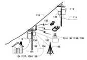
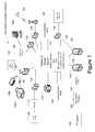
- FIG. 1is a block diagram of a example communication system relying on a variety of communications media, including power lines, wired and wireless media;
- FIG. 2is a block diagram of a portion of a communication system including an overhead power line network
- FIG. 3is a block diagram of a portion of a communication system including an underground power line network
- FIG. 4is a block diagram of an example embodiment of a backhaul device
- FIG. 5illustrates an implementation of an example embodiment of a backhaul device capable of transmitting data over a variety of communications media
- FIG. 6is a block diagram of an example embodiment of an access device.
- FIG. 7illustrates an implementation of an example embodiment of an access device capable of transmitting data over a variety of communications media.
- the communications network of the present inventionmay provide high data rate internet access, mobile telephone communications, broadband communications, streaming video and audio services, and other communication services to each home, building or other structure, and to each room, office, apartment, or other unit or sub-unit of a multi-unit structure.
- the power line wireless networkmay provide these communication services to mobile and stationary devices in outdoor areas such as customer premises yards, parks, stadiums, and also to public and semi-public indoor areas such as subway trains, subway stations, train stations, airports, restaurants, public and private automobiles, bodies of water (e.g., rivers, bays, inlets, etc.), building lobbies, elevators, etc.
- FIG. 1shows components of a communication network 104 that may rely, in part, on portions of the power system infrastructure 101 to carry data communications.
- the communication network 104includes a plurality of communication nodes which communicate with each other and other devices via power lines and other communication media.
- Various user devices 130 and power line communication devicesmay transmit and receive data over the links to communicate via an IP network 126 (e.g., the Internet).
- IP network 126e.g., the Internet
- One type of communication node 128may be a backhaul node 132 .
- Another type of communication node 128may be an access node 134 .
- Another type of communication node 128may be a repeater node 135 .
- a given node 128may serve as a backhaul node 132 , access node 134 , and/or repeater node 135 .
- One type of communication linkis formed between two communication nodes 128 over a communication medium. Some links may be formed over MV power lines 110 or over LV power lines 114 . Other communication links of the communication network 104 may be wireless links. Still other links may be formed over coaxial cables, such as gigabit-Ethernet links 152 , 154 . Thus, some communication links may be formed using a portion 101 of the power system infrastructure, while other links may be formed over another communication media.
- the links formed by wired or wireless mediamay occur at any point along a communication path between a backhaul node 132 and a user device 130 (e.g., between a backhaul node 132 and an access node 134 ; between an access node 134 and another access node 134 ; between an access node 134 and a user device 130 ), or between a backhaul node 132 and a distribution point 127 or aggregation point 124 .
- Each communication node 128may be formed by one or more communication devices.
- Communication nodes (and devices) which communicate over a power line mediumare referred to herein as a power line communication device.
- Exemplary power line communication devicesinclude a backhaul device 138 (see FIG. 4 ), an access device 139 (see FIG. 6 ), and a repeater 135 .
- Such devicesmay include a modem, which may implement various signal sets, such as a HomePlug signal set, a WiMAX (Worldwide Interoperability for Microwave Access also sometimes referred to as WirelessMAN or conforming to IEEE 802.16) signal set, or another signal set.
- Communication nodes which communicate wirelesslymay include an access point, a mobile telephone cell site, a WiMAX wireless transceiver, or other wireless modem.
- Communication nodes which communicate over a coaxial cablemay include a cable modem.
- Communication nodes which communicate over a twisted pair wiremay include a DSL modem or other modem.
- a given communication nodetypically will communicate in two directions (either full duplex or half duplex), which may be over the same or different types of communication media. Accordingly, a communication node may include one, two or more communication devices.
- a backhaul node 132may serve as an interface between a power line portion (e.g., an MV power line 110 ) and an aggregation point 124 that may provide a connection to an IP network 126 .
- the communication network 104preferably includes one or more backhaul nodes 132 disposed over a geographical area such as a city. Upstream communications from user premises may be communicated to an access node 134 , to a backhaul node 132 , and then transmitted to an aggregation point 124 which is linked to the IP network 126 .
- the backhaul node 132may be coupled to the aggregation point 124 directly or indirectly (i.e., via one or more intermediate nodes).
- the backhaul node 132may communicate with its upstream device via any of several alternative communication media, such as a fiber optic (digital or analog (e.g., Wave Division Multiplexed), coaxial cable, WiMAX, IEEE 802.11, twisted pair (e.g., DSL), and/or another wired or wireless media.
- Downstream communications from the IP network 126typically are communicated through the aggregation point 124 to the backhaul node 132 .
- the aggregation point 124typically includes an Internet Protocol (IP) network data packet router and is connected to an IP network backbone, thereby providing access to an IP network 126 (i.e., the AP 124 can be connected to or form part of a point of presence or POP). Any available mechanism may be used to link the aggregation point 124 to the POP or other device (e.g., fiber optic conductors, T-carrier, Synchronous Optical Network (SONET), and wireless techniques).
- IPInternet Protocol
- An access node 134may serve one or more user devices 130 or other network destinations.
- Upstream datamay be transmitted, for example, from a user device 130 to an access node 134 via a communication medium (e.g., an LV power line 114 ) coupled to an access node 134 or wirelessly.
- the datais routed through the network 104 to a backhaul node 132 , (or a local destination, such as another user device 130 ).
- Downstream datais sent through the network 104 to a user device 130 via an access node 134 .
- Exemplary user devices 130include a computer 130 a , LAN, a WLAN, router 130 b , Voice-over IP endpoint, game system, personal digital assistant (PDA), mobile telephone, digital cable box, power meter, gas meter, water meter, security system, alarm system (e.g., fire, smoke, carbon dioxide, security/burglar, etc.), stereo system, television, fax machine 130 c , HomePlug residential network, or other device having a data interface.
- a user device 130may include or be coupled to a modem to communicate with a given access node 134 .
- Exemplary modemsinclude a power line modem 136 , a wireless modem, a cable modem 131 , a DSL modem or other suitable transceiver device.
- a repeater node 135may receive and re-transmit data (i.e., repeat), for example, to extend the communications range of other communication elements.
- backhaul nodes 132 and access nodes 134also may serve as repeater nodes 135 (e.g., for other access nodes and other backhaul nodes 132 ).
- Repeatersmay also be stand-alone devices without additional functionality.
- Repeaters 135may be coupled to and repeat data on MV power lines or LV power lines (and, for the latter, be coupled to the internal or external LV power lines).
- FIG. 2shows an overhead portion 136 of an example embodiment of the communication network 104 in which some signals may be communicated along overhead power lines.
- FIG. 3shows an underground portion 137 of an example embodiment of the communication system 104 in which some signals may be communicated along underground power lines.
- an underground power line communication network portion 137may couple to an overhead power line, or be coupled to an overhead power line communication network portion 136 .
- broadband data signalsmay propagate along medium voltage (MV) power lines 110 and low voltage (LV) power lines 114 .
- MV power lines 110distribute medium level power voltages to a region or local area. Typical voltage levels on the MV power lines 110 range from about 1000 V to about 100 kV.
- LV power lines 114carry low level power voltages to households, office, building units and other types of premises. Typical voltage levels on LV power lines 114 range from about 100 V to about 240 V.
- the MV power line voltagesare stepped down at distribution transformers 112 to provide low voltage power signals carried by the LV power lines 114 .
- a device for bypassing the transformer 112may be included.
- the deviceis part of an access device 139 forming part of an access node 134 .
- This example access device 134may be coupled to an MV power line 110 and a LV power line 114 and may bridge data around the distribution transformer 112 (i.e., to bypass the transformer 112 ).
- the access device 139may transmit the data signal onto both the MV power line 110 and LV power line 114 , onto either of the MV power line 110 or LV power line 114 , and/or onto an alternative communication medium.
- the access device 139may also act as a repeater by receiving data from the MV power line 110 and transmitting that data back onto the MV power line 110 .
- access devices 139may be coupled to the MV power line 110 on each side of a distribution transformer 112 .
- the communication network 104may provide high data rate internet access and other high data-rate services (e.g., data; voice; video) to user devices 130 in homes, buildings and other structures, and to each room, office, apartment, or other unit or sub-unit of multi-unit structure. In doing so, a communication link is formed between two communication nodes 128 over a communication medium. As described above, the communication links may be formed by power lines, non-power line wired media, and wireless media, and may occur at any point along a communication path between a backhaul node 132 and a user device 130 , or between a backhaul node 132 and a distribution point 127 or aggregation point 124 .
- high data-rate servicese.g., data; voice; video
- Communication among nodes 128may occur using a variety of protocols and media.
- protocolssuch as IEEE 802.11 a/b/g, 802.16, 1G, 2G, 3G, a satellite communication protocol such as WildBlue®, Ethernet, multipoint microwave distribution system (MMDS) standards, DOCSIS (Data Over Cable System Interface Specification) signal standards or another suitable communication protocol may be implemented (depending on the medium).
- the wireless linksmay also use any suitable frequency band.
- frequency bandsare used that are selected from among ranges of licensed frequency bands (e.g., 6 GHz, 11 GHz, 18 GHz, 23 GHz, 24 GHz, 28 GHz, or 38 GHz band) and unlicensed frequency bands (e.g., 900 MHz, 2.4 GHz, 5.8 Ghz, 24 GHz, 38 GHz, or 60 GHz (i.e., 57-64 GHz)).
- licensed frequency bandse.g., 6 GHz, 11 GHz, 18 GHz, 23 GHz, 24 GHz, 28 GHz, or 38 GHz band
- unlicensed frequency bandse.g., 900 MHz, 2.4 GHz, 5.8 Ghz, 24 GHz, 38 GHz, or 60 GHz (i.e., 57-64 GHz)
- the communications among nodesmay be OFDMA, time division multiple access (TDMA) and/or frequency division multiple access (FDMA) and also may comprise point to multi-point communications and/or point to point communications.
- the nodes 128may use time division multiplexing and implement one or more layers of the 7 layer open systems interconnection (OSI) model.
- OSIopen systems interconnection
- the devices and softwaremay implement switching and routing technologies, and create logical paths, known as virtual circuits, for transmitting data from node to node.
- error handling, congestion control and packet sequencingcan be performed at Layer 3 .
- Layer 2 ‘data link’ activitiesinclude encoding and decoding data packets and handling errors of the ‘physical’ layer 1 , along with flow control and frame synchronization.
- the configuration of the various communication nodesmay vary.
- modemas used herein is meant to refer to a modem chip, modem chip set, or modem integrated circuit, which form part of a larger communication device.
- a scalable orthogonal frequency division multiplexing (OFDM) schememay be implemented.
- OFDMis a technique for transmitting large amounts of digital data using multiple carriers over a frequency band. Specifically, in OFDM communications a single transmitter transmits on many (typically dozens to thousands) of different orthogonal frequencies. Typically, the frequencies are closely spaced so that each sub-carrier carries a narrowband signal.
- An OFDM carrier signalis the sum of the orthogonal sub-carriers, with baseband data on each sub-carrier being independently modulated, such as by quadrature amplitude modulation (QAM) or quadrature phase-shift keying (QPSK).
- QAMquadrature amplitude modulation
- QPSKquadrature phase-shift keying
- the nodes 128via their respective modems, employ Orthogonal Frequency Division Multiple Access (OFDMA) over the MV power line.
- OFDMAOrthogonal Frequency Division Multiple Access
- the modem 141may be included at a communication node to transmit and receive communications over a power line.
- the modem 141may implement a variety of features including adaptive transmit power control of sub-carriers adaptive modulation, and a versatile signal set, and may be coupled to a variety of communications media.
- modem 141may be configured to transmit using adaptive transmission power of OFDM sub-carriers. This includes the ability of the modem to control (increase or decrease) the transmission power of one or more sub-carriers over a plurality of power levels.
- one example embodiment of the present inventioncan be configured to adjust the power level of one or more sub-carriers to one of a plurality of power levels (e.g., voltage levels), which may be between a maximum power level and zero. In other words, this example embodiment may adjust the transmission power of one or more sub-carriers to any of five, ten, twenty, or more power levels (depending on the implementation and/or conditions).
- the overall transmission poweri.e., the transmission power over the entire band of sub-carriers
- the overall transmission powermay remain substantially the same (i.e., the same as if a moderate and equal transmission power was used across all sub-carriers) and within federal limits while allowing more reliable communications over greater distances than previous modems.
- Another advantage of implementing adaptive transmit power of sub-carriers within OFDM for power line communicationsis that transmissions are controllable at a sub-channel level (e.g., on one or more sub-carriers), as well as at a channel level (all carriers or some subset group of sub-carriers) thereby allowing control of radiated transmissions.
- the systemcan be flexible to ensure that the system does not interfere with other communications.
- adaptive transmit power scalingmay permit the use of different transmission power levels in different locations, different frequencies, or under different circumstances.
- the modem 141can be configured to communicate via a selected frequency band (which can vary over time and/or for device, application, user and/or group thereof).
- Adaptive transmit power of sub-carriersmay allow individual users, applications, device(s), or groups of users, applications or devices, to be designated a power level according to needs. For example, a device requiring a lower QOS and/or bandwidth may be designated lower transmission power for its sub-channel, while a device requiring higher QOS and/or bandwidth may have the transmission power adapted higher for its communications.
- the sub-channel (sub-carriers and frequency band)may be the same, different or partial overlapping for the two or more devices. Likewise the transmissions may or may not be simultaneous. Lower power also may allow for enhanced frequency re-use among adjacent medium voltage power line subnets and may be preferred when sufficient. Transmit power of sub-carriers may be manually or system assigned statically, by a commanding network management system or controller module or may be dynamically allocated and reallocated according to changing system topologies, or the changing needs users, applications or devices.
- adaptive transmit power scalingpermits transmitting data signals at reduced (or zero) power at a first set of frequencies within a channel (e.g., frequency bands known to be used by another communication system), while maintaining (or increasing) power at other frequencies within the channel. This is sometimes referred to as notching.
- a channele.g., frequency bands known to be used by another communication system
- adaptive transmit power scalingto notch sub-carriers, interference with other communication systems may be reduced.
- any multi-carrier modeme.g., modem chip or chip set
- the receiving modem of like kindmight not be capable of receiving the notched signal if, for example, the notch covers too many sub-carriers and the present example embodiment may not need such external notch filtering.
- the modem 141also may implement adaptive modulation.
- Power Line communications utilizing adaptive modulationmay vary the modulation scheme by channel in a multi-channel system.
- the modulation schememay be varied by sub-channel. For example, some frequency bands (e.g., a sub-channel comprised of one or more carriers) may use one modulation scheme, while another band uses a different modulation scheme (during a simultaneous or contemporaneous transmission/reception). Further, the modulation scheme may be varied within a sub-channel over time as conditions change or due to other factors.
- Modulation schemesalso may be modified by intervention (e.g., via receiving a command from an external device) or automatically (e.g., as a result of the execution of program code stored in memory of the modem 141 or controller in operative communication with the modem 141 ) based upon (e.g., detection of) system load, type and/or number of applications being supported, number of users, signal to noise ratio, error rate, data rate, and/or other parameter(s).
- Modulation schemes used in this example embodimentmay include 16 QAM, 64 QAM, and QPSK.
- the modem 141may be coupled to one or more different communication media, such as a MV power line 110 , a LV power line 114 , a coaxial cable, a twisted pair, and a wireless medium (e.g., an antenna).
- a 3 db splittermay be coupled to the modem 141 to split the signal for transmission over for communication over more than one of the various communications media.
- a frequency translation circuitmay be used to couple the modem 141 to one or more media (e.g., to the power line).
- a signal set of a modem 141 substantially compatible with, substantially conforming to, or certified to the IEEE 802.16 (d and/or e) standardmay be implemented, in which the signal frequencies are shifted to a desired frequency (e.g., downbanded to the desired frequency band).
- the modemsmay be substantially compatible with an IEEE 802.16 (e) standard or (d) standard.
- WiMAXis an acronym that stands for Worldwide Interoperability for Microwave Access. It is a technology generally known for delivering last mile wireless broadband access as an alternative to cable and DSL broadband access.
- WiMAXis intended for wireless applications
- a signal set (or modem) substantially compatible with WiMAXmay be adapted according to an embodiment of this invention to transmit and receive communications over an alternative communications medium, such as a medium voltage power line, a low voltage power line, or a coaxial cable.
- an alternative communications mediumsuch as a medium voltage power line, a low voltage power line, or a coaxial cable.
- some embodiments of the modem 141may implement a signal set substantially compatible with the HomePlug 1.0, or A/V standard, but may not include various features described herein.
- some example embodiments of the modem 141may implement a common Media Access Control (MAC) layer for all physical layer PHY adaptations (e.g., single carrier; 256 OFDM; 2048 OFDMA).
- the MACmay provide a Time Division Multiplex (TDM) downlink coupled with Time Division Multiple Access (TDMA) access in the uplink.
- TDMTime Division Multiplex
- TDMATime Division Multiple Access
- One example modemmay implement Scalable (Scaleable) OFDM, which includes a mechanism by which the sub-carrier spacing is independent of the bandwidth and the number of used sub carriers (and Fast Fourier Transform (FFT) size) scales with bandwidth.
- ScalableScalable OFDM
- FFTFast Fourier Transform
- the modem 141(and devices in communication with the modem 141 ), may use all the bandwidth that is already allocated to it and also may make requests (and grant the requests from other devices) for additional bandwidth. Such requests (and replies granting or denying the requests) may be transmitted over the power line conductor(s).
- communication devicesmay change MAC and/or PHY parameters based upon software instructions. Examples of parameters that may be changed in this manner may include: frequency, channel size, sub-channel number, sub-channel on/off or sub-channel power adaptions, modulation type either per channel or sub channel, or by time and/or by MAC address, and/or MAC block.
- communication devicesmay change MAC and PHY parameters and capabilities based upon information of the environment. For example, parameters and capabilities may be changed based upon information related to: system load; type and/or number of applications being supported; number of users and/or user devices; prioritization levels of network traffic; service level agreements (e.g., QoS) of users and/or user devices; failure of a device or service; and historical behavior of the system, projections based upon historical behaviors of the system, and/or projections based upon historical behaviors of the system and/or other information.
- the informationmay become known via detection by the modem itself, by receiving information transmitted from another device, and/or via other means.
- modemmay be configured to vary the size of frames and the size of individual slots within the frames on a frame by frame basis.
- the modemmay also be configured to provide Quality of Service (QoS) via one of: real time polling, non-real time polling, best effort, or constant bit rate grant.
- QoSQuality of Service
- the modemmay be configured to provide forward error correction via Reed-Solomon and convolutional coding.
- the modemmay be adapted communicate via a wide delay spread values such as a root-mean-square delay spread from 1 ⁇ s (or below) to 10 ⁇ s (or above).
- Each communication node 128may be formed by one or more communication devices.
- Communication nodes which communicate over a power line mediuminclude a power line communication device.
- Exemplary power line communication devicesinclude a backhaul point 138 (see FIGS. 4 and 5 ), an access device 139 (also referred to as a power line bridge) (see FIGS. 6 and 7 ), a repeater, and a power line modem 136 (see FIG. 1 ).
- Communication nodes which communicate via a wireless mediummay include a wireless access point having at least a wireless transceiver (which may comprise a mobile telephone base station (e.g., a micro or pico cell site) or WiMAX base station).
- Communication nodes which access a link over a coaxial cablemay include a cable modem.
- Communication nodes which access a link over a T-1 wiremay include a DSL modem.
- a communication nodemay include a modem 141 which allows a common modem to be used for communications over multiple media such as one or more of a power line, a coaxial cable, a twisted pair and a wireless medium.
- a backhaul point 138 , access device 139 or repeater 135may establish links over MV power lines 110 , LV power lines 114 , other wired media, and wireless link.
- a given communication node 128may communicate in two or more directions establishing multiple communication links, which may be formed along the same or different types of communication media.
- a backhaul node 132may communicate to and from the communication network 104 via a backhaul node 132 .
- a backhaul node 132comprises a backhaul device 138 .
- the backhaul device 138may transmit communications directly to an aggregation point 124 , or to a distribution point 127 which in turn transmits the data to an aggregation point 124 .
- FIGS. 4 and 5show an example embodiment of a backhaul device 138 which may form all or part of a backhaul node 132 .
- the backhaul device 138may include a medium voltage power line interface (MV Interface) 140 , a controller 142 , an expansion port 146 , and a gigabit Ethernet (gig-E) switch 148 .
- the backhaul device 138also may include a low voltage power line interface (LV interface) 144 .
- the MV interfaceis used to communication over the MV power lines and in this example embodiment includes an MV power line coupler coupled to an MV signal conditioner, which is coupled to modem 141 a as described above according to an embodiment of this invention.
- the MV power line couplerprevents the medium voltage power signal from passing from the MV power line 110 to the rest of the device's circuitry, while allowing the communications signal to pass between the backhaul device 138 and the MV power line 110 .
- the MV signal conditionermay provide one or more of amplification, filtering, frequency translation, and transient voltage protection of data signals communicated over the MV power lines 110 .
- the MV signal conditionermay be formed by a filter, amplifier, a mixer and local oscillator, and/or other circuits which provide transient voltage protection.
- the modem 141 amay demodulate, decrypt, and decode data signals received from the MV signal conditioner and may encode, encrypt, and modulate data signals to be provided to the MV signal conditioner.
- the backhaul device 138also may include a low voltage power line interface (LV Interface) 144 for receiving and transmitting data over an LV power line 114 .
- the LV interface 144may include an LV power line coupler coupled to an LV signal conditioner, coupled to a modem 141 b , according to an embodiment of this invention.
- the LV power line couplermay be an inductive coupler.
- the LV power line couplermay be a conductive coupler.
- the LV signal conditionermay provide one or more of amplification, filtering, frequency translation, and/or transient voltage protection of data signals communicated over the LV power lines 114 . Data signals received by the LV signal conditioner may be provided to the modem 141 .
- the LV signal conditionermay be formed by a filter, amplifier, a mixer and local oscillator, and/or other circuits which provide transient voltage protection.
- the modem 141 bmay demodulate, decrypt, and decode data signals received from the LV signal conditioner and may encode, encrypt, and modulate data signals to be provided to the LV signal conditioner.
- the backhaul device 138also may include an expansion port 146 , which may be used to connect to a variety of devices.
- an antennamay be coupled to the expansion port 146 to enable wireless transmission and reception to and from the controller 142 .
- a wireless access pointwhich may include a wireless transceiver or modem, may be integral to or coupled to the expansion port 146 .
- Said wireless modem or the controller 142may establish and maintain a communication link 150 .
- a communication linkis established and maintained via expansion port 146 over an alternative communications medium (e.g., fiber optic, cable, twisted pair) using an alternative transceiver device.
- an alternative communications mediume.g., fiber optic, cable, twisted pair
- the expansion port 146may provide an Ethernet connection allowing communications with various devices over optical fiber, coaxial cable or other wired medium.
- the modemmay be an Ethernet transceiver (fiber or copper), the modem 141 as described herein, or another suitable modem (e.g., cable modem, DSL modem).
- the expansion portmay be coupled to a Wifi access point (IEEE 802.11 transceiver), WiMAX modem, or mobile telephone cell site.
- the expansion port 146may be employed to establish a communication link 150 between the backhaul device 138 and devices at a residence, building, other structure, another fixed location, or between the backhaul device 138 and a mobile wireless device.
- various sensorsalso may be connected to the backhaul device 138 through the expansion port 146 .
- Exemplary sensing devices that may be coupled to the backhaul device 138 through the expansion port 146include a current sensor, power usage sensing device, a level sensor (to determine pole tilt), a camera (e.g., for monitoring security, detecting motion, monitoring children's areas, monitoring a pet area), an audio input device (e.g., microphone for monitoring children, detecting noises), a vibration sensor, a motion sensor (e.g., an infrared motion sensor for security), a home security system, a smoke detector, a heat detector, a carbon monoxide detector, a natural gas detector, a thermometer, a barometer, a biohazard detector, a water or moisture sensor, a temperature sensor, and a light sensor.
- a current sensore.g., power usage sensing device, a level sensor (to determine pole tilt), a camera (e.g., for monitoring security, detecting motion, monitoring
- the backhaul device 138also may include a gigabit Ethernet (Gig-E) switch 148 .
- Gigabit Ethernetis a term describing various technologies for implementing Ethernet networking at a nominal data rate of one gigabit per second, as defined by the IEEE 802.3z and 802.3ab standards.
- Gigabit EthernetThere are a number of different physical layer standards for implementing gigabit Ethernet using optical fiber, twisted pair cable, or balanced copper cable. Accordingly the gig-E switch may be rated at 1 gigabit per second (or greater as for a 10 gigabit Ethernet switch).
- the switch 148may be included in the same housing or co-located with the other components of the node (e.g., mounted at or near the same utility pole or transformer).
- the gig-E switch 148maintains a table of which communication devices are connected to which switch 148 port (e.g., based on MAC address).
- the switch receiving the packetdetermines the data packet's destination address and forwards the packet towards the destination device rather than to every device in a given network. This greatly increases the potential data rate of the network because collisions are substantially reduced or eliminated, and multiple communications may occur simultaneously.
- the gig-E switch 148may include an upstream port for maintaining a communication link 152 with an upstream device (e.g., a backhaul node 132 , an aggregation point 124 , a distribution point 127 ), a downstream port for maintaining a communication link 152 with a downstream device (e.g., another backhaul node 134 ; an access node 134 ), and a local port for maintaining a communication link 154 to a Gig-E compatible device such as a mobile telephone cell cite 155 (i.e., base station), an access node 134 , another backhaul node 132 , or another device.
- the gig-E switch 148may include additional ports.
- the Gig-E switch 148may be connected to a mobile telephone cell site (via link 154 ) configured to provide mobile telephone communications (digital or analog) and use the signal set and frequency bands suitable to communicate with mobile phones, PDAs, and other devices configured to communicate over a mobile telephone network.
- Mobile telephone network and mobile telephone communications of mobile telephone cell sitesare meant to include analog and digital cellular telephone networks and communications, respectively, including, but not limited to AMPS, 1G, 2G, 3G, GSM (Global System for Mobile communications), PCS (Personal Communication Services) (sometimes referred to as digital cellular networks), and other cellular telephone networks.
- One or more of these networksmay use various access technologies such as frequency division multiple access (FDMA), time division multiple access (TDMA), or code division multiple access (CDMA) (e.g., some of which may be used by 2G devices) and others may use CDMA2000 (based on 2G Code Division Multiple Access), WCDMA (UMTS)—Wideband Code Division Multiple Access, or TD-SCDMA (e.g., some of which may be used by 3G devices).
- FDMAfrequency division multiple access
- TDMAtime division multiple access
- CDMAcode division multiple access
- CDMA2000based on 2G Code Division Multiple Access
- WCDMAUMTS
- TD-SCDMAWideband Code Division Multiple Access
- Communicationsmay be input to the gig-E switch 148 from the MV interface 140 , LV interface 144 or expansion port 146 through the controller 142 . Communications also may be input from each of the upstream port, local port and downstream port.
- the gig-E switch 148may be configured (by the controller 142 dynamically) to direct the input data from a given input port through the switch 148 to the upstream port, local port, or downstream port. Communications received at the upstream port or downstream port need not be provided (if so desired) to the controller 142 . Specifically, communications received at the upstream port or downstream port need not be buffered or otherwise stored in the controller memory or processed by the controller.
- the controller 142controls the gig-E switch 148 , allowing the switch 148 to pass data upstream and downstream (e.g. according to parameters (e.g., prioritization, rate limiting, etc.) provided by the controller).
- the backhaul device 138also may include a controller 142 which controls the operation of the device 138 .
- the backhaul 138may also include a router (for routing, bridging, or switching functionality), which routes data along an appropriate path (e.g., determining a destination for the data).
- the controllerincludes program code for performing routing (hereinafter to also include switching and/or bridging).
- the controller 142may maintain a table of which communication devices are connected to port in memory.
- the controller 142matches data packets with specific messages (e.g., control messages) and destinations, performs traffic control functions, performs usage tracking functions, authorizing functions, throughput control functions and similar related services.
- Communications entering the backhaul device 138 from the MV power lines 110 at the MV interface 140are received, and then may be routed to the LV interface 144 , expansion port 146 or gig-E switch 148 .
- Communications entering the backhaul device 138 from the LV power lines 114 at the LV interface 144are received, and may then be routed to the MV interface 140 , the expansion port 146 , or the gig-E switch 148 .
- Communications entering the backhaul point 138 from the expansion port 146are received, and may then be routed to the MV interface 140 , the LV interface 144 , or the gig-E switch 148 .
- the controller 142may receive data from the MV interface 140 , LV interface 144 or the expansion port 146 , and may route the received data to the MV interface 140 , LV interface 144 , the expansion port 146 , or gig-E switch 148 .
- user datamay be routed based on the destination address of the packet (e.g., the IP destination address). Not all data packets, of course, are routed. Some packets received may not have a destination address for which the particular backhaul device 138 routes data packets (and may be ignored). Additionally, some data packets may be addressed directly to the backhaul device 138 in which case the backhaul device may process the data as a control message.
- a given backhaul node 32may maintain communication links with multiple access nodes 134 via one or more MV power lines.
- a different communication channelmay be assigned to each communication link managed by the backhaul node 132 .
- communications over the MV power line 110 using a modem 141may transmit within a frequency range of approximately 2-50 MHz.
- a MV power line communication sub-channelto be an approximately 4 MHz frequency band. Within such a 48 MHz frequency band, approximately 12 sub-channels of approximately 4 MHz per sub-channel may be assigned for communicating through the given backhaul node 132 . Respective sub-channels may be turned on and off as needed.
- the backhaul nodes 132may communicate with user devices 130 via one or more access nodes 134 , which may include an access device 139 .
- FIGS. 6 and 7show an example embodiment of such an access device 139 for providing communication services to mobile devices and to user devices 130 at a residence, building, or other location.
- access devices 139provide communication services for user devices 130 such as security management; IP network protocol (IP) packet routing; data filtering; access control; service level monitoring; service level management; signal processing; and modulation/demodulation of signals transmitted over the communication medium.
- IPIP network protocol
- the access device 139take the form of a bypass device that moves data between an MV power line 110 and an LV power line 114 .
- the access device 139may include a medium voltage power line interface (MV Interface) 140 having a modem 141 c as described above, a low voltage power line interface (LV interface) 144 having a modem 141 d as described above, a controller 142 , and an expansion port 146 .
- the MV interface 140 , modems 141 c - d , LV interface 144 , controller 142 and expansion port 146may have the functionality and functional components as previously described above with regard to FIG. 4 and the backhaul device 138 .
- the access device 139also may include a gigabit Ethernet (gig-E) port 156 .
- the gig-E port 156maintains a connection using a gigabit Ethernet protocol as described above for the gig-E switch 148 of FIG.
- the Gig-E port 156may maintain an Ethernet connection for communicating with various devices over optical fiber, coaxial cable or other wired medium. For example, a communication link 157 may be maintained between the access device 139 and another device through the gig-E port 156 .
- the gig-E port 156may provide a connection to user devices 130 , sensors (as described above with regard to the expansion port 146 ), or a base station or other wireless device.
- Communicationsmay be received at the access device 139 through the MV interface 140 , LV interface 144 , expansion port 146 or gig-E port 156 .
- communicationsmay enter the access device 139 from the MV power lines 110 through the MV interface 140 , and then may be routed to the LV interface 142 , expansion port 146 or gig-E port 156 .
- Communicationsmay enter the access device 139 from the LV power lines 114 through the LV interface 144 , and then may be routed to the MV interface 140 , the expansion port 146 , or the gig-E port 156 .
- Communicationsmay enter the access device 139 from the expansion port 146 , and then may routed to the MV interface 140 , the LV interface 144 , or the gig-E port 156 . Communications may enter the access device 139 via the gig-E port 156 , and then may be routed to the MV interface 140 , the LV interface 144 , or the expansion port 146 .
- the controller 142controls communications through the access device 139 .
- the access device 139receives data from the MV interface 140 , LV interface 144 , the expansion port 146 , or the gig-E port 156 and may route the data to the MV interface 140 , LV interface 144 , expansion port 146 , or gig-E port 156 under the direction of the controller 142 based on a routing table or other information (i.e., it determines a destination for the data).
- the access node 134may be coupled to a backhaul node 132 via a wired medium coupled to Gig-E port 156 while in another embodiment, the access node 134 may be coupled to the backhaul node 132 via an MV power line (via MV interface 140 ). In yet another embodiment, the access node 134 may be coupled to a backhaul node 132 via a wireless link (via expansion port 146 or Gig-E port 156 ).
- a given access device 139may communicate with a backhaul node 132 , another access node 134 , a power line modem 136 , or another communication device over various communications media.
- the modem 141is coupled to a splitter which divides a signal transmitted from the modem 141 c or 141 d along separate paths for coupling to one or more of a power line, a coaxial cable, a twisted pair and/or a wireless medium.
- incoming communicationsmay be received at the modem 141 through any of the various communications media via the splitter.
- the transmitted and received communicationsmay be upbanded or downbanded (in frequency) according to a communication frequency being used by a particular communication medium.
- the access device's modem 141 dmay receive the communication and then upband the communication to an appropriate sub-channel within the range of 4-50 MHz for transmission along a MV power line 110 .
- the received signal form the user devicemay be upbanded (or downbanded) to an appropriate sub-channel (without demodulating the received signal) for wired transmission over the MV power line or other media (to the backhaul node) or for wireless retransmission.
- communications received over via MV power line 110may be upbanded for wireless transmission to the user device or downbanded for transmission over the LV power lines 114 without demodulation.
- the transmitted and received communicationsmay be upbanded or downbanded for communicating over a coaxial cable, twisted pair, or other media.
- a subset of sub-carriersmay be allocated to an individual user (e.g. from an access node), application or device, or groups of users, applications or devices (e.g., PLC device such an access node). This may be used to create a sub-channel for individual user devices, application or device (e.g., PLC device) or groups of user devices, applications or devices (e.g., PLC devices).
- Sub-carriersmay be manually or system assigned statically, by a commanding network management system or controller module, or may be dynamically allocated and reallocated according to changing system topologies, or the changing needs users, applications or devices.
- Such assignment and change of assignmentmay be performed via software running in the controller operating the device which may detect conditions or receive a command from the network management system.
- sixteen sets of twelve sub-carrierseach are defined, where one, two, four, eight or all sets can be assigned to a user device or access node.
- each access nodemay communicate with a backhaul node via a different sub-channel over the MV power lines.
- Each sub-channelmay be further divided into two sub-channels (for a FDMA system) or may be used by the two devices in time slots (for a TDMA system).
- Access nodes more distant from the backhaul nodesmay be allocated a lower frequency sub-channel because higher frequencies tend to attenuate more quickly over power lines.
- access nodes more near the backhaul nodemay be designated a lower transmission power (e.g., so that said transmissions are not received by, and do not interfere with, access nodes communicating with different backhaul nodes connected to the same the MV power line).
- a repeatere.g., indoor, outdoor, low voltage (LVR) and/or medium voltage
- LVRlow voltage
- a repeaterserves to extend the communication range of other communication elements (e.g., access devices, backhaul devices, and other nodes).
- the repeatermay be coupled to power lines (e.g., MV power line; LV power line) and other communication media (e.g., fiber optical cable, coaxial cable, T-1 line or wireless medium).
- power linese.g., MV power line; LV power line
- other communication mediae.g., fiber optical cable, coaxial cable, T-1 line or wireless medium.
- a repeater node 135may also include a device for providing a link to a user device 130 (and thus also serve as an access node 134 ).
- the repeater 135may be located at or in the vicinity of a utility meter for the premises.
- the repeatermay be plugged into a wall outlet within the premises.
- a user device 130may be coupled to an access node 134 along a communication path that includes one or more forms of communications media.
- an access node 134may be coupled to a communication device at a subscriber's premises by a LV power line 114 .
- an access node 134may be coupled to a communication device at a subscriber's premises by a coaxial cable, twisted pair or wireless media.
- Such communication devicemay include a modem 141 (e.g., forming part of power line modem device 136 ) having a capability of coupling to a power line and other communications media according.
- modem device 136may implement a versatile signal set via modem 141 as previously described.
- the power line modem device 136may be coupled to a user device 130 directly or along various communication paths.
- a user device 130may be coupled to the power line modem device 136 by a coaxial cable and cable modem, by a twisted pair and a DSL modem, by wireless media and a wireless transceiver, or by an internal LV power line and a power line modem device (e.g., a power line modem implementing a HomePlug 1.0 or A/V standard).
- the modemmay be replaced with a frequency translation device that does not demodulate the data.
- a frequency-shifted, substantially WiMAX compatible signal set(or other signal set) is that a communication may be transmitted along alternative communications media.
- a power line communication received at access node 134e.g., from backhaul node 132
- a subscribermay use fixed wireless customer premise equipment (CPE) to receive the signal.
- Upstream datais similarly received wirelessly from a user device at the access node 134 , filtered, downbanded, amplified, and coupled to the MV power line.
- CPEfixed wireless customer premise equipment
- a communicationsuch as a communication using the frequency shifted WiMAX signal set, traverses an LV power line 114 (or coaxial cable) into customer premises to a user communication device plugged into a wall outlet.
- the received signalmay be amplified, filtered, upbanded, amplified and wirelessly transmitted to a remote user device.
- a multiple in/multiple out (MMO) antennamay be located at the subscriber's structure, such as at a power meter. Communications may be received from the access device 139 into the premises through the MIMO antenna, or transmitted from the premises via the MIMO antenna to the access device 139 .
- a modem 141 as described abovemay be coupled to the MIMO antenna to transmit and receive communications. Downstream communications may be transmitted toward the user device from the modem 141 along any of various communications media, (e.g., power line, coaxial cable, twisted pair, wireless). Similarly upstream communications may be received at the modem 141 along any of such various communications media.
- mobile telephone communicationsalso may be received at the MIMO antenna and power line modem device 136 .
- Such communicationsmay be retransmitted from the modem 141 wirelessly within the home to a mobile phone or other wireless device using a licensed or unlicensed frequency band.
- the communication network 104may be monitored and controlled via a power line server that may be remote from the structure and physical location of the network elements.
- the controller of the nodes 128 described hereinmay include executable program code for controlling the operation of the nodes and responding to commands from the PLS received wirelessly or via the MV power line or other media.
- the PLSmay transmit any number of commands to a backhaul nodes 132 and access nodes 134 to manage the system (via the power lines or other media). As will be evident to those skilled in the art, most of these commands are equally applicable for backhaul nodes 132 and access nodes 134 .
- These commandsmay include altering configuration information, synchronizing the time of the node 128 with that of the PLS, controlling measurement intervals (e.g., voltage measurements), requesting measurement or data statistics, requesting the status of user device activations, rate limiting/shaping, and requesting reset or other system-level commands. Any or all of these commands may require a unique response from the node 128 , which may be transmitted by the node 128 and received and stored by the PLS.
- the PLSmay include software to transmit a command to any or all of the nodes ( 134 and 132 ) to schedule a voltage and/or current measurement at any particular time so that all of the network elements of the PLCS take the measurement(s) at the same time.
- the PLSmay transmit software to be executed by the nodes.
- the nodes 128may communicate over a neutral conductor (that extends to a home or that extends between transformers) of the power distribution system instead of or in addition to the energized conductors (e.g., MV or LV power lines).
- a neutral conductorthat extends to a home or that extends between transformers of the power distribution system instead of or in addition to the energized conductors (e.g., MV or LV power lines).
Landscapes
- Engineering & Computer Science (AREA)
- Computer Networks & Wireless Communication (AREA)
- Signal Processing (AREA)
- Power Engineering (AREA)
- Cable Transmission Systems, Equalization Of Radio And Reduction Of Echo (AREA)
- Small-Scale Networks (AREA)
Abstract
Description
Claims (49)
Priority Applications (1)
| Application Number | Priority Date | Filing Date | Title |
|---|---|---|---|
| US11/462,123US7804763B2 (en) | 2005-04-04 | 2006-08-03 | Power line communication device and method |
Applications Claiming Priority (2)
| Application Number | Priority Date | Filing Date | Title |
|---|---|---|---|
| US11/097,132US7265664B2 (en) | 2005-04-04 | 2005-04-04 | Power line communications system and method |
| US11/462,123US7804763B2 (en) | 2005-04-04 | 2006-08-03 | Power line communication device and method |
Related Parent Applications (1)
| Application Number | Title | Priority Date | Filing Date |
|---|---|---|---|
| US11/097,132Continuation-In-PartUS7265664B2 (en) | 2005-04-04 | 2005-04-04 | Power line communications system and method |
Publications (2)
| Publication Number | Publication Date |
|---|---|
| US20070002772A1 US20070002772A1 (en) | 2007-01-04 |
| US7804763B2true US7804763B2 (en) | 2010-09-28 |
Family
ID=46325849
Family Applications (1)
| Application Number | Title | Priority Date | Filing Date |
|---|---|---|---|
| US11/462,123Expired - Fee RelatedUS7804763B2 (en) | 2005-04-04 | 2006-08-03 | Power line communication device and method |
Country Status (1)
| Country | Link |
|---|---|
| US (1) | US7804763B2 (en) |
Cited By (10)
| Publication number | Priority date | Publication date | Assignee | Title |
|---|---|---|---|---|
| US20110044404A1 (en)* | 2008-03-31 | 2011-02-24 | Nxp B.V. | Digital modulator |
| US20110043340A1 (en)* | 2009-08-19 | 2011-02-24 | Texas Instruments Incorporated | Concatenated Repetition Code with Convolutional Code |
| US20110063433A1 (en)* | 2009-09-11 | 2011-03-17 | Thonhauser Gmbh | Absorbance measurements using portable electronic devices with built-in camera |
| US20120307917A1 (en)* | 2011-06-06 | 2012-12-06 | Mariana Goldhamer | Connecting various wireless terminals over power lines |
| US20140092943A1 (en)* | 2011-06-02 | 2014-04-03 | Haritel Inc. | Method for using power lines for wireless communication |
| US8760854B2 (en) | 2011-06-09 | 2014-06-24 | Florida Power And Light Company | Gateway node |
| DE102014211994A1 (en)* | 2014-06-23 | 2016-01-07 | Power Plus Communications Ag | System and method for communication via a multi-phase medium-voltage link and network and control unit |
| US20160149689A1 (en)* | 2014-11-24 | 2016-05-26 | Panasonic Intellectual Property Management Co., Ltd. | Communication apparatus and communication method |
| US9369179B2 (en) | 2013-11-30 | 2016-06-14 | Wally Hariz | Method for using power lines for wireless communication |
| US9461705B2 (en) | 2014-11-25 | 2016-10-04 | Qualcomm Incorporated | Power back-off for limiting emissions and power consumption |
Families Citing this family (59)
| Publication number | Priority date | Publication date | Assignee | Title |
|---|---|---|---|---|
| US7248158B2 (en)* | 2000-04-14 | 2007-07-24 | Current Technologies, Llc | Automated meter reading power line communication system and method |
| US6842459B1 (en)* | 2000-04-19 | 2005-01-11 | Serconet Ltd. | Network combining wired and non-wired segments |
| IL154921A (en)* | 2003-03-13 | 2011-02-28 | Mosaid Technologies Inc | Telephone system having multiple distinct sources and accessories therefor |
| IL159838A0 (en)* | 2004-01-13 | 2004-06-20 | Yehuda Binder | Information device |
| IL161869A (en) | 2004-05-06 | 2014-05-28 | Serconet Ltd | System and method for carrying a wireless based signal over wiring |
| US20060255930A1 (en)* | 2005-05-12 | 2006-11-16 | Berkman William H | Power line communications system and method |
| US7558206B2 (en)* | 2005-06-21 | 2009-07-07 | Current Technologies, Llc | Power line communication rate limiting system and method |
| US7508834B2 (en)* | 2005-06-21 | 2009-03-24 | Current Technologies, Llc | Wireless link for power line communications system |
| US20070054622A1 (en)* | 2005-09-02 | 2007-03-08 | Berkman William H | Hybrid power line wireless communication system |
| US7675897B2 (en)* | 2005-09-06 | 2010-03-09 | Current Technologies, Llc | Power line communications system with differentiated data services |
| US7856007B2 (en)* | 2005-10-21 | 2010-12-21 | Current Technologies, Llc | Power line communication voice over IP system and method |
| US7813451B2 (en) | 2006-01-11 | 2010-10-12 | Mobileaccess Networks Ltd. | Apparatus and method for frequency shifting of a wireless signal and systems using frequency shifting |
| US20070171925A1 (en)* | 2006-01-25 | 2007-07-26 | Murata Kikai Kabushiki Kaisha | Multiplex superposed communication device |
| US20080012724A1 (en)* | 2006-01-30 | 2008-01-17 | Corcoran Kevin F | Power line communications module and method |
| US20070201540A1 (en)* | 2006-02-14 | 2007-08-30 | Berkman William H | Hybrid power line wireless communication network |
| US20080039089A1 (en)* | 2006-08-11 | 2008-02-14 | Berkman William H | System and Method for Providing Dynamically Configurable Wireless Communication Network |
| US20080056338A1 (en)* | 2006-08-28 | 2008-03-06 | David Stanley Yaney | Power Line Communication Device and Method with Frequency Shifted Modem |
| US20080112473A1 (en)* | 2006-11-09 | 2008-05-15 | Rami Refaeli | System and method for communicating with multi compartment vehicles |
| US7894329B1 (en)* | 2007-04-24 | 2011-02-22 | At&T Intellectual Property Ii, L.P. | Method and system for providing broadband access to a data network via gas pipes |
| US20090067361A1 (en)* | 2007-09-08 | 2009-03-12 | Califano Joseph N | Cellular Phone Signal Enhancement Apparatus |
| US8594133B2 (en) | 2007-10-22 | 2013-11-26 | Corning Mobileaccess Ltd. | Communication system using low bandwidth wires |
| US8175649B2 (en) | 2008-06-20 | 2012-05-08 | Corning Mobileaccess Ltd | Method and system for real time control of an active antenna over a distributed antenna system |
| US8301314B2 (en)* | 2009-01-29 | 2012-10-30 | S&C Electric Company | System and method for providing voltage regulation in a power distribution network |
| WO2010089719A1 (en) | 2009-02-08 | 2010-08-12 | Mobileaccess Networks Ltd. | Communication system using cables carrying ethernet signals |
| US9271057B2 (en)* | 2010-02-22 | 2016-02-23 | Qualcomm Incorporated | Methods and apparatus for time synchronization and measurement of power distribution systems |
| TWI411345B (en)* | 2010-08-20 | 2013-10-01 | Wu Sheng Huang | Plug-and-play wireless network extension system and method of automatic connection for the same |
| US20120134395A1 (en)* | 2010-11-30 | 2012-05-31 | Texas Instruments Incorporated | Power Line Communications (PLC) Across Different Voltage Domains Using Multiple Frequency Subbands |
| WO2012084221A2 (en)* | 2010-12-23 | 2012-06-28 | Lantiq Deutschland Gmbh | Noise reduction between networks |
| US9077819B2 (en)* | 2011-04-11 | 2015-07-07 | Mediatek Inc. | Transmission power control method |
| US8855701B2 (en) | 2011-04-11 | 2014-10-07 | Mediatek Inc. | Dynamic transmission power control method |
| EP2525503B1 (en)* | 2011-05-16 | 2018-03-07 | Sony Corporation | Power line communication modem, power line communication system, power line communication method |
| EP2829152A2 (en) | 2012-03-23 | 2015-01-28 | Corning Optical Communications Wireless Ltd. | Radio-frequency integrated circuit (rfic) chip(s) for providing distributed antenna system functionalities, and related components, systems, and methods |
| US9667315B2 (en)* | 2012-09-05 | 2017-05-30 | Landis+Gyr Technologies, Llc | Power distribution line communications with compensation for post modulation |
| US20160013552A1 (en)* | 2014-07-11 | 2016-01-14 | Sony Corporation | Operating an Antenna Device of a User Equipment |
| US9184960B1 (en) | 2014-09-25 | 2015-11-10 | Corning Optical Communications Wireless Ltd | Frequency shifting a communications signal(s) in a multi-frequency distributed antenna system (DAS) to avoid or reduce frequency interference |
| US9853676B2 (en)* | 2014-09-30 | 2017-12-26 | Apple Inc. | Alternative routing of wireless data onto power supply |
| US9742462B2 (en) | 2014-12-04 | 2017-08-22 | At&T Intellectual Property I, L.P. | Transmission medium and communication interfaces and methods for use therewith |
| US11025460B2 (en)* | 2014-11-20 | 2021-06-01 | At&T Intellectual Property I, L.P. | Methods and apparatus for accessing interstitial areas of a cable |
| US10009067B2 (en) | 2014-12-04 | 2018-06-26 | At&T Intellectual Property I, L.P. | Method and apparatus for configuring a communication interface |
| US9997819B2 (en) | 2015-06-09 | 2018-06-12 | At&T Intellectual Property I, L.P. | Transmission medium and method for facilitating propagation of electromagnetic waves via a core |
| EP3226428A4 (en)* | 2014-11-24 | 2017-10-04 | Panasonic Intellectual Property Management Co., Ltd. | Communication device and communication method |
| US9306624B1 (en) | 2015-03-31 | 2016-04-05 | Landis+Gyr Technologies, Llc | Initialization of endpoint devices joining a power-line communication network |
| US9461707B1 (en) | 2015-05-21 | 2016-10-04 | Landis+Gyr Technologies, Llc | Power-line network with multi-scheme communication |
| US10756805B2 (en)* | 2015-06-03 | 2020-08-25 | At&T Intellectual Property I, L.P. | Client node device with frequency conversion and methods for use therewith |
| US10812174B2 (en) | 2015-06-03 | 2020-10-20 | At&T Intellectual Property I, L.P. | Client node device and methods for use therewith |
| US10490245B2 (en) | 2017-10-02 | 2019-11-26 | Micron Technology, Inc. | Memory system that supports dual-mode modulation |
| US10446198B2 (en) | 2017-10-02 | 2019-10-15 | Micron Technology, Inc. | Multiple concurrent modulation schemes in a memory system |
| US10355893B2 (en) | 2017-10-02 | 2019-07-16 | Micron Technology, Inc. | Multiplexing distinct signals on a single pin of a memory device |
| US11403241B2 (en) | 2017-10-02 | 2022-08-02 | Micron Technology, Inc. | Communicating data with stacked memory dies |
| US10725913B2 (en) | 2017-10-02 | 2020-07-28 | Micron Technology, Inc. | Variable modulation scheme for memory device access or operation |
| CN108953835A (en)* | 2017-11-22 | 2018-12-07 | 深圳市博铭维智能科技有限公司 | A kind of detecting robot of pipe system |
| US10778415B2 (en)* | 2018-01-19 | 2020-09-15 | Cox Communications, Inc. | Systems and methods for disabling physical modules in network switches using encryption |
| US10686493B2 (en) | 2018-03-26 | 2020-06-16 | At&T Intellectual Property I, L.P. | Switching of data channels provided in electromagnetic waves and methods thereof |
| US10547545B2 (en)* | 2018-03-30 | 2020-01-28 | At&T Intellectual Property I, L.P. | Method and apparatus for switching of data channels provided in electromagnetic waves |
| CN109587656A (en)* | 2018-12-31 | 2019-04-05 | 广东超讯通信技术股份有限公司 | A kind of communication means, wireless fidelity device and terminal device |
| US10930992B1 (en) | 2019-12-03 | 2021-02-23 | At&T Intellectual Property I, L.P. | Method and apparatus for communicating between waveguide systems |
| US10812291B1 (en) | 2019-12-03 | 2020-10-20 | At&T Intellectual Property I, L.P. | Method and apparatus for communicating between a waveguide system and a base station device |
| US20240275647A1 (en)* | 2023-02-10 | 2024-08-15 | Avago Technologies International Sales Pte. Limited | Boost metric based pre-eq limiting systems and methods |
| CN116389214B (en)* | 2023-06-05 | 2023-08-08 | 四川科冠电子有限公司 | Noise reduction method, noise reduction terminal and medium suitable for voltage power line carrier communication |
Citations (71)
| Publication number | Priority date | Publication date | Assignee | Title |
|---|---|---|---|---|
| US1547242A (en) | 1924-04-29 | 1925-07-28 | American Telephone & Telegraph | Carrier transmission over power circuits |
| US4504705A (en) | 1982-01-18 | 1985-03-12 | Lgz Landis & Gyr Zug Ag | Receiving arrangements for audio frequency signals |
| US4517548A (en) | 1982-12-20 | 1985-05-14 | Sharp Kabushiki Kaisha | Transmitter/receiver circuit for signal transmission over power wiring |
| US4636771A (en) | 1984-12-10 | 1987-01-13 | Westinghouse Electric Corp. | Power line communications terminal and interface circuit associated therewith |
| US4668934A (en) | 1984-10-22 | 1987-05-26 | Westinghouse Electric Corp. | Receiver apparatus for three-phase power line carrier communications |
| US5185591A (en) | 1991-07-12 | 1993-02-09 | Abb Power T&D Co., Inc. | Power distribution line communication system for and method of reducing effects of signal cancellation |
| EP0581351A1 (en) | 1992-07-24 | 1994-02-02 | ITALTEL SOCIETA ITALIANA TELECOMUNICAZIONI s.p.a. | Transceiver for the exchange of informations along lines for the transport of electric power |
| US5351272A (en) | 1992-05-18 | 1994-09-27 | Abraham Karoly C | Communications apparatus and method for transmitting and receiving multiple modulated signals over electrical lines |
| GB2315937A (en) | 1996-08-01 | 1998-02-11 | Northern Telecom Ltd | TDMA power line communication transceiver using amplifier with reverse direction bypass |
| US5777544A (en) | 1997-03-17 | 1998-07-07 | Intellon Corporation | Apparatus and method for controlling data communications having combination of wide and narrow band frequency protocols |
| JPH10200544A (en) | 1997-01-14 | 1998-07-31 | Matsushita Electric Works Ltd | Communication system |
| ES2122920A1 (en) | 1996-12-19 | 1998-12-16 | Blazquez Fernando A Beltran | Digital modulator/demodulator adapted to the HSS (Home System Specification) standard for transmitting data via the electricity network. |
| US5995572A (en) | 1996-02-19 | 1999-11-30 | Ascom Tech Ag | Method for measuring frequency shift in digital communications using synchronization sequence and channel step response |
| WO2000016496A2 (en) | 1998-09-15 | 2000-03-23 | Siemens Aktiengesellschaft | Arrangement and method for forming an overall signal, device and method for forming a current signal and a first communication signal, communication system and method for transmitting a first overall signal and a second overall signal |
| EP1011235A2 (en) | 1998-12-15 | 2000-06-21 | Nortel Networks Corporation | Reception of multicarrier signals over power lines |
| DE10008602A1 (en) | 2000-02-24 | 2001-06-07 | Siemens Ag | Data processing device with power supply and power supply for data processing devices |
| WO2001050625A2 (en) | 1999-12-30 | 2001-07-12 | Siemens Aktiengesellschaft | Conversion of a two-directional so data stream for transmission via a low voltage power network |
| WO2001063787A1 (en) | 2000-02-24 | 2001-08-30 | Siemens Aktiengesellschaft | External modem |
| US6313738B1 (en) | 1997-06-09 | 2001-11-06 | At&T Corp. | Adaptive noise cancellation system |
| US6331814B1 (en) | 1999-11-25 | 2001-12-18 | International Business Machines Corporation | Adapter device for the transmission of digital data over an AC power line |
| DE10012235C2 (en) | 2000-03-14 | 2001-12-20 | Siemens Ag | Circuit arrangement for data transmission on the energy supply lines of an electrical energy supply network |
| US20010054953A1 (en)* | 2000-04-14 | 2001-12-27 | Kline Paul A. | Digital communications utilizing medium voltage power distribution lines |
| US20020041228A1 (en) | 2000-10-10 | 2002-04-11 | George Zhang | Apparatus for power line computer network system |
| US20020060624A1 (en) | 2000-11-17 | 2002-05-23 | George Zhang | Plug compatible power line communications network device |
| US6396392B1 (en)* | 2000-05-23 | 2002-05-28 | Wire21, Inc. | High frequency network communications over various lines |
| US20020080010A1 (en) | 2000-12-22 | 2002-06-27 | George Zhang | Power line communications network device for DC powered computer |
| US20020095662A1 (en) | 2000-10-25 | 2002-07-18 | Ashlock Robert L. | Utilizing powerline networking as a general purpose transport for a variety of signals |
| US20020098867A1 (en) | 1999-05-25 | 2002-07-25 | Meiksin Zvi H. | Powerline communication system |
| US20020097953A1 (en) | 2000-12-15 | 2002-07-25 | Kline Paul A. | Interfacing fiber optic data with electrical power systems |
| US20020109585A1 (en)* | 2001-02-15 | 2002-08-15 | Sanderson Lelon Wayne | Apparatus, method and system for range extension of a data communication signal on a high voltage cable |
| US20020110310A1 (en)* | 2001-02-14 | 2002-08-15 | Kline Paul A. | Method and apparatus for providing inductive coupling and decoupling of high-frequency, high-bandwidth data signals directly on and off of a high voltage power line |
| US20020110311A1 (en)* | 2001-02-14 | 2002-08-15 | Kline Paul A. | Apparatus and method for providing a power line communication device for safe transmission of high-frequency, high-bandwidth signals over existing power distribution lines |
| US20020118101A1 (en)* | 2001-02-14 | 2002-08-29 | Kline Paul A. | Data communication over a power line |
| EP1021866B1 (en) | 1997-06-10 | 2002-10-23 | Nortel Networks Limited | Data transmission over a power line communications system |
| US6480510B1 (en) | 1998-07-28 | 2002-11-12 | Serconet Ltd. | Local area network of serial intelligent cells |
| DE10119040A1 (en) | 2001-04-18 | 2002-12-05 | Siemens Ag | Data transmission system over current supply network with data signal input |
| DE10119039A1 (en) | 2001-04-18 | 2002-12-05 | Siemens Ag | Apparatus for transmitting data via electrical mains network, amplifies data signal using switched amplifier and couples into power network |
| DE10026931C2 (en) | 2000-05-30 | 2003-01-23 | Siemens Ag | PLC system for high bit rate data communications |
| DE10026930C2 (en) | 2000-05-30 | 2003-01-30 | Siemens Ag | Method for reducing interference in the transmission of communication signals over lines |
| WO2003009083A2 (en) | 2001-07-17 | 2003-01-30 | Main.Net Communications Ltd. | Dual purpose power line modem |
| WO2003010896A1 (en) | 2001-07-23 | 2003-02-06 | Main.Net Communications Ltd. | Dynamic power line access connection |
| US6522650B1 (en) | 2000-08-04 | 2003-02-18 | Intellon Corporation | Multicast and broadcast transmission with partial ARQ |
| US20030062990A1 (en) | 2001-08-30 | 2003-04-03 | Schaeffer Donald Joseph | Powerline bridge apparatus |
| US20030071721A1 (en)* | 2001-08-04 | 2003-04-17 | Manis Constantine N. | Adaptive radiated emission control |
| WO2003040732A2 (en) | 2001-11-09 | 2003-05-15 | Power Plus Communications Ag | Impedance stabilization network for determining the electromagnetic interfering radiation of a modem |
| DE10147916C1 (en) | 2001-09-28 | 2003-05-28 | Siemens Ag | Method and transmission device for recognizing the transmission state of transmission devices connected to power supply lines |
| DE10146982C1 (en) | 2001-09-24 | 2003-06-18 | Siemens Ag | Charging device for mobile communication devices with integrated Powerline modem |
| WO2003056715A1 (en) | 2001-12-10 | 2003-07-10 | Jorma Romunen | Controlling of data transmission voltage level by cutting principle in low voltage net |
| US20030169155A1 (en) | 2000-04-14 | 2003-09-11 | Mollenkopf James Douglas | Power line communication system and method of using the same |
| US20030224784A1 (en) | 2002-05-28 | 2003-12-04 | Amperion, Inc. | Communications system for providing broadband communications using a medium voltage cable of a power system |
| US20040001499A1 (en) | 2002-06-26 | 2004-01-01 | Patella James Philip | Communication buffer scheme optimized for voip, QoS and data networking over a power line |
| US20040037214A1 (en)* | 2000-12-18 | 2004-02-26 | Blasco Claret Jorge Vicente | Point to multipoint system and process for the transmission over the electricity network of digital data |
| US20040110483A1 (en) | 2002-12-10 | 2004-06-10 | Mollenkopf James Douglas | Power line communication sytem and method |
| US20040113756A1 (en) | 2002-12-10 | 2004-06-17 | Mollenkopf James Douglas | Device and method for coupling with electrical distribution network infrastructure to provide communications |
| US20040113757A1 (en) | 2002-12-10 | 2004-06-17 | White Melvin Joseph | Power line communication system and method of operating the same |
| US20040212481A1 (en)* | 2000-05-23 | 2004-10-28 | Satius, Inc. | High frequency network multiplexed communications over various lines using multiple modulated carrier frequencies |
| US20040223617A1 (en) | 2003-05-08 | 2004-11-11 | Corcoran Kevin F. | Power line communication device and method of using the same |
| US20040227622A1 (en) | 2003-05-13 | 2004-11-18 | Giannini Paul M. | Device and method for communicating data signals through multiple power line conductors |
| US20040227621A1 (en) | 2000-04-14 | 2004-11-18 | Cope Leonard D. | Power line communication apparatus and method of using the same |
| US20040242185A1 (en) | 2003-05-29 | 2004-12-02 | Amperion, Inc. | Method and device for frequency translation in powerline communications |
| US20040266332A1 (en) | 2002-10-02 | 2004-12-30 | Lang Jack Arnold | Communication methods and apparatus |
| US20050063422A1 (en) | 2003-09-19 | 2005-03-24 | Sashi Lazar | Communication protocol over power line communication networks |
| US6891796B1 (en)* | 1998-12-23 | 2005-05-10 | Arkados, Inc. | Transmitting data in a power line network using link quality assessment |
| US20050128057A1 (en) | 1999-11-15 | 2005-06-16 | Mansfield Amos R. | Preventing unintended communication among power line communication devices associated with different premises power distribution lines of an electric power distribution system |
| US20050164666A1 (en) | 2002-10-02 | 2005-07-28 | Lang Jack A. | Communication methods and apparatus |
| US20050226200A1 (en)* | 2004-03-26 | 2005-10-13 | Edgecom | A Power Line Communication System that Enables Low-Cost Last Mile Access to any Legacy or Emerging Network Infrastructure |
| US20050254442A1 (en)* | 2004-05-13 | 2005-11-17 | Widefi, Inc. | Non-frequency translating repeater with detection and media access control |
| US7142094B1 (en) | 2002-02-20 | 2006-11-28 | Current Grid, Llc | Last leg power grid high-speed data transmitter and receiver structures |
| US20060290476A1 (en)* | 2005-06-28 | 2006-12-28 | International Broadband Electric Communications, Inc. | Improved Coupling of Communications Signals to a Power Line |
| US7206320B2 (en)* | 2003-06-18 | 2007-04-17 | Sony Corporation | Method and apparatus for non-centralized network bandwidth management |
| US7269403B1 (en)* | 2004-06-03 | 2007-09-11 | Miao George J | Dual-mode wireless and wired power line communications |
Family Cites Families (2)
| Publication number | Priority date | Publication date | Assignee | Title |
|---|---|---|---|---|
| US6133738A (en)* | 1998-10-02 | 2000-10-17 | Minarovic; Joe T. | Detectable transponder reel housing |
| JP2005019669A (en)* | 2003-06-26 | 2005-01-20 | Matsushita Electric Ind Co Ltd | Polishing pad, polishing device and method for polishing wafer |
- 2006
- 2006-08-03USUS11/462,123patent/US7804763B2/ennot_activeExpired - Fee Related
Patent Citations (80)
| Publication number | Priority date | Publication date | Assignee | Title |
|---|---|---|---|---|
| US1547242A (en) | 1924-04-29 | 1925-07-28 | American Telephone & Telegraph | Carrier transmission over power circuits |
| US4504705A (en) | 1982-01-18 | 1985-03-12 | Lgz Landis & Gyr Zug Ag | Receiving arrangements for audio frequency signals |
| US4517548A (en) | 1982-12-20 | 1985-05-14 | Sharp Kabushiki Kaisha | Transmitter/receiver circuit for signal transmission over power wiring |
| US4668934A (en) | 1984-10-22 | 1987-05-26 | Westinghouse Electric Corp. | Receiver apparatus for three-phase power line carrier communications |
| US4636771A (en) | 1984-12-10 | 1987-01-13 | Westinghouse Electric Corp. | Power line communications terminal and interface circuit associated therewith |
| US5185591A (en) | 1991-07-12 | 1993-02-09 | Abb Power T&D Co., Inc. | Power distribution line communication system for and method of reducing effects of signal cancellation |
| US5351272A (en) | 1992-05-18 | 1994-09-27 | Abraham Karoly C | Communications apparatus and method for transmitting and receiving multiple modulated signals over electrical lines |
| EP0581351A1 (en) | 1992-07-24 | 1994-02-02 | ITALTEL SOCIETA ITALIANA TELECOMUNICAZIONI s.p.a. | Transceiver for the exchange of informations along lines for the transport of electric power |
| US5995572A (en) | 1996-02-19 | 1999-11-30 | Ascom Tech Ag | Method for measuring frequency shift in digital communications using synchronization sequence and channel step response |
| GB2315937A (en) | 1996-08-01 | 1998-02-11 | Northern Telecom Ltd | TDMA power line communication transceiver using amplifier with reverse direction bypass |
| ES2122920A1 (en) | 1996-12-19 | 1998-12-16 | Blazquez Fernando A Beltran | Digital modulator/demodulator adapted to the HSS (Home System Specification) standard for transmitting data via the electricity network. |
| JPH10200544A (en) | 1997-01-14 | 1998-07-31 | Matsushita Electric Works Ltd | Communication system |
| US5777544A (en) | 1997-03-17 | 1998-07-07 | Intellon Corporation | Apparatus and method for controlling data communications having combination of wide and narrow band frequency protocols |
| US6313738B1 (en) | 1997-06-09 | 2001-11-06 | At&T Corp. | Adaptive noise cancellation system |
| EP1021866B1 (en) | 1997-06-10 | 2002-10-23 | Nortel Networks Limited | Data transmission over a power line communications system |
| US6480510B1 (en) | 1998-07-28 | 2002-11-12 | Serconet Ltd. | Local area network of serial intelligent cells |
| WO2000016496A2 (en) | 1998-09-15 | 2000-03-23 | Siemens Aktiengesellschaft | Arrangement and method for forming an overall signal, device and method for forming a current signal and a first communication signal, communication system and method for transmitting a first overall signal and a second overall signal |
| EP1011235A3 (en) | 1998-12-15 | 2002-05-02 | Nortel Networks Limited | Reception of multicarrier signals over power lines |
| EP1011235A2 (en) | 1998-12-15 | 2000-06-21 | Nortel Networks Corporation | Reception of multicarrier signals over power lines |
| US6891796B1 (en)* | 1998-12-23 | 2005-05-10 | Arkados, Inc. | Transmitting data in a power line network using link quality assessment |
| US20020098867A1 (en) | 1999-05-25 | 2002-07-25 | Meiksin Zvi H. | Powerline communication system |
| US20020098868A1 (en) | 1999-05-25 | 2002-07-25 | Meiksin Zvi H. | Through-the-earth communication system |
| US20050128057A1 (en) | 1999-11-15 | 2005-06-16 | Mansfield Amos R. | Preventing unintended communication among power line communication devices associated with different premises power distribution lines of an electric power distribution system |
| US6331814B1 (en) | 1999-11-25 | 2001-12-18 | International Business Machines Corporation | Adapter device for the transmission of digital data over an AC power line |
| WO2001050625A2 (en) | 1999-12-30 | 2001-07-12 | Siemens Aktiengesellschaft | Conversion of a two-directional so data stream for transmission via a low voltage power network |
| WO2001063787A1 (en) | 2000-02-24 | 2001-08-30 | Siemens Aktiengesellschaft | External modem |
| DE10008602A1 (en) | 2000-02-24 | 2001-06-07 | Siemens Ag | Data processing device with power supply and power supply for data processing devices |
| DE10012235C2 (en) | 2000-03-14 | 2001-12-20 | Siemens Ag | Circuit arrangement for data transmission on the energy supply lines of an electrical energy supply network |
| US20030169155A1 (en) | 2000-04-14 | 2003-09-11 | Mollenkopf James Douglas | Power line communication system and method of using the same |
| US6958680B2 (en) | 2000-04-14 | 2005-10-25 | Current Technologies, Llc | Power line communication system and method of using the same |
| US20040227621A1 (en) | 2000-04-14 | 2004-11-18 | Cope Leonard D. | Power line communication apparatus and method of using the same |
| US20010054953A1 (en)* | 2000-04-14 | 2001-12-27 | Kline Paul A. | Digital communications utilizing medium voltage power distribution lines |
| US6965302B2 (en) | 2000-04-14 | 2005-11-15 | Current Technologies, Llc | Power line communication system and method of using the same |
| US6396392B1 (en)* | 2000-05-23 | 2002-05-28 | Wire21, Inc. | High frequency network communications over various lines |
| US20040212481A1 (en)* | 2000-05-23 | 2004-10-28 | Satius, Inc. | High frequency network multiplexed communications over various lines using multiple modulated carrier frequencies |
| DE10026931C2 (en) | 2000-05-30 | 2003-01-23 | Siemens Ag | PLC system for high bit rate data communications |
| DE10026930C2 (en) | 2000-05-30 | 2003-01-30 | Siemens Ag | Method for reducing interference in the transmission of communication signals over lines |
| US6522650B1 (en) | 2000-08-04 | 2003-02-18 | Intellon Corporation | Multicast and broadcast transmission with partial ARQ |
| US20020041228A1 (en) | 2000-10-10 | 2002-04-11 | George Zhang | Apparatus for power line computer network system |
| US20020095662A1 (en) | 2000-10-25 | 2002-07-18 | Ashlock Robert L. | Utilizing powerline networking as a general purpose transport for a variety of signals |
| US20020060624A1 (en) | 2000-11-17 | 2002-05-23 | George Zhang | Plug compatible power line communications network device |
| US20020097953A1 (en) | 2000-12-15 | 2002-07-25 | Kline Paul A. | Interfacing fiber optic data with electrical power systems |
| US20040037214A1 (en)* | 2000-12-18 | 2004-02-26 | Blasco Claret Jorge Vicente | Point to multipoint system and process for the transmission over the electricity network of digital data |
| US20020080010A1 (en) | 2000-12-22 | 2002-06-27 | George Zhang | Power line communications network device for DC powered computer |
| US6950567B2 (en) | 2001-02-14 | 2005-09-27 | Current Technologies, Llc | Method and apparatus for providing inductive coupling and decoupling of high-frequency, high-bandwidth data signals directly on and off of a high voltage power line |
| US20020118101A1 (en)* | 2001-02-14 | 2002-08-29 | Kline Paul A. | Data communication over a power line |
| US20020110310A1 (en)* | 2001-02-14 | 2002-08-15 | Kline Paul A. | Method and apparatus for providing inductive coupling and decoupling of high-frequency, high-bandwidth data signals directly on and off of a high voltage power line |
| US20020154000A1 (en) | 2001-02-14 | 2002-10-24 | Kline Paul A. | Data communication over a power line |
| US20020110311A1 (en)* | 2001-02-14 | 2002-08-15 | Kline Paul A. | Apparatus and method for providing a power line communication device for safe transmission of high-frequency, high-bandwidth signals over existing power distribution lines |
| US20020121963A1 (en) | 2001-02-14 | 2002-09-05 | Kline Paul A. | Data communication over a power line |
| US20020109585A1 (en)* | 2001-02-15 | 2002-08-15 | Sanderson Lelon Wayne | Apparatus, method and system for range extension of a data communication signal on a high voltage cable |
| DE10119040A1 (en) | 2001-04-18 | 2002-12-05 | Siemens Ag | Data transmission system over current supply network with data signal input |
| DE10119039A1 (en) | 2001-04-18 | 2002-12-05 | Siemens Ag | Apparatus for transmitting data via electrical mains network, amplifies data signal using switched amplifier and couples into power network |
| US20040174851A1 (en) | 2001-07-17 | 2004-09-09 | Yeshayahu Zalitzky | Dual purpose power line modem |
| WO2003009083A2 (en) | 2001-07-17 | 2003-01-30 | Main.Net Communications Ltd. | Dual purpose power line modem |
| WO2003010896A1 (en) | 2001-07-23 | 2003-02-06 | Main.Net Communications Ltd. | Dynamic power line access connection |
| US20030071721A1 (en)* | 2001-08-04 | 2003-04-17 | Manis Constantine N. | Adaptive radiated emission control |
| US20030062990A1 (en) | 2001-08-30 | 2003-04-03 | Schaeffer Donald Joseph | Powerline bridge apparatus |
| DE10146982C1 (en) | 2001-09-24 | 2003-06-18 | Siemens Ag | Charging device for mobile communication devices with integrated Powerline modem |
| DE10147916C1 (en) | 2001-09-28 | 2003-05-28 | Siemens Ag | Method and transmission device for recognizing the transmission state of transmission devices connected to power supply lines |
| WO2003040732A2 (en) | 2001-11-09 | 2003-05-15 | Power Plus Communications Ag | Impedance stabilization network for determining the electromagnetic interfering radiation of a modem |
| WO2003056715A1 (en) | 2001-12-10 | 2003-07-10 | Jorma Romunen | Controlling of data transmission voltage level by cutting principle in low voltage net |
| US7142094B1 (en) | 2002-02-20 | 2006-11-28 | Current Grid, Llc | Last leg power grid high-speed data transmitter and receiver structures |
| US20030224784A1 (en) | 2002-05-28 | 2003-12-04 | Amperion, Inc. | Communications system for providing broadband communications using a medium voltage cable of a power system |
| US20040001499A1 (en) | 2002-06-26 | 2004-01-01 | Patella James Philip | Communication buffer scheme optimized for voip, QoS and data networking over a power line |
| US20050164666A1 (en) | 2002-10-02 | 2005-07-28 | Lang Jack A. | Communication methods and apparatus |
| US20040266332A1 (en) | 2002-10-02 | 2004-12-30 | Lang Jack Arnold | Communication methods and apparatus |
| US6965303B2 (en) | 2002-12-10 | 2005-11-15 | Current Technologies, Llc | Power line communication system and method |
| US20040113757A1 (en) | 2002-12-10 | 2004-06-17 | White Melvin Joseph | Power line communication system and method of operating the same |
| US20040113756A1 (en) | 2002-12-10 | 2004-06-17 | Mollenkopf James Douglas | Device and method for coupling with electrical distribution network infrastructure to provide communications |
| US20040110483A1 (en) | 2002-12-10 | 2004-06-10 | Mollenkopf James Douglas | Power line communication sytem and method |
| US20040223617A1 (en) | 2003-05-08 | 2004-11-11 | Corcoran Kevin F. | Power line communication device and method of using the same |
| US20040227622A1 (en) | 2003-05-13 | 2004-11-18 | Giannini Paul M. | Device and method for communicating data signals through multiple power line conductors |
| US20040242185A1 (en) | 2003-05-29 | 2004-12-02 | Amperion, Inc. | Method and device for frequency translation in powerline communications |
| US7206320B2 (en)* | 2003-06-18 | 2007-04-17 | Sony Corporation | Method and apparatus for non-centralized network bandwidth management |
| US20050063422A1 (en) | 2003-09-19 | 2005-03-24 | Sashi Lazar | Communication protocol over power line communication networks |
| US20050226200A1 (en)* | 2004-03-26 | 2005-10-13 | Edgecom | A Power Line Communication System that Enables Low-Cost Last Mile Access to any Legacy or Emerging Network Infrastructure |
| US20050254442A1 (en)* | 2004-05-13 | 2005-11-17 | Widefi, Inc. | Non-frequency translating repeater with detection and media access control |
| US7269403B1 (en)* | 2004-06-03 | 2007-09-11 | Miao George J | Dual-mode wireless and wired power line communications |
| US20060290476A1 (en)* | 2005-06-28 | 2006-12-28 | International Broadband Electric Communications, Inc. | Improved Coupling of Communications Signals to a Power Line |
Non-Patent Citations (20)
| Title |
|---|
| "Archnet: Automatic Meter Reading System Power Line Carrier Communication", www.archnetco.com/english/product/product-sl.htm, (2001). |
| "HomePlug 1.01 Specification", HomePlug Powerline Alliance, (Dec. 1, 2001),1-39. |
| "HomePlug Initital Draft Medium Interface Specification", HomePlug Powerline Alliance, (Jul. 27, 2000),1-109. |
| "HomePlug Initital Draft Medium Interface Specification", HomePlug Powerline Alliance, (May 19, 2000),1-109. |
| "HomePlug Powerline Alliance,", HomePlug 0.5 Draft Medium Interface Specification,, (Nov. 28, 2000),1-133. |
| "IEEE Guide for Power-Line Carrier Applications, ANSI/IEEE Std 643-1980", The Institute of Electrical and Electronics Engineers, Inc., (1980),1-80. |
| "Summary of an IEEE Guide for Power-Line Carrier Applications", IEEE Transactions on Power Apparatus and Systems, (Nov./Dec. 1980),2334-2337. |
| Bernard Sklar, Digital Communications Fundamentals and Applications, 2001, Prentice Hall PTR, Second Edition, pp. 117-119, 522-523.* |
| Chang, SS L., "Power-Line Carrier", Fundamentals Handbook of Electrical and Computer Engineering, vol. II-Communication, Control, Devices and Systems, (1983),617-627. |
| Chen, Y-F et al., "Baseband Transceiver Design of a 128-Kbps Power-Line Modem for Household Applications", IEEE Transactions on Power Delivery, (2002),338-344. |
| De Wilde, W R., et al., "Upwards to a Reliable Bi-Directional Communication Link on the LV Power Supplies for Utility Services: Field Tests in Belgium", Sixth International Conference on, (Apr. 3-5, 1990),168-172. |
| Dostert, K "EMC Aspects of High Speed Powerline Communications", Proceedings of the 15th International Wroclaw Symposium and Exhibition on Electromagnetic Capability, (Jun. 27-30, 2000),98-102. |
| Gutzwiller, F W., et al., "Homenet: A Control Network for Consumer Applications", IEEE Transactions on Consumer Electronics, (Aug. 1983),297-304. |
| IEEE 100, The Authoritative Dictionary of IEEE Standards Terms, Dec. 2000, Seventh Edition, p. 993.* |
| Kim, W-O et al., "A Control Network Architecture Based on EIA-709.1 Protocol for Power Line Data Communications", IEEE Transactions on Consumer Electronics, (2002),650-655. |
| Nichols, K "Build a Pair of Line-Carrier Modems", CRC Electronics-Radio Electronics, (1988),87-91. |
| Onunga, J et al., "Distribution Line Communications Using CSMA Access Control with Priority Acknowledgements", IEEE Transactions on Power Delivery, (Apr. 1989),878-886. |
| Pete McArthur, Amped Up and Ready to Go, Sep. 2004, IEEE Spectrum, pp. 14-18.* |
| Piety, R A., "Intrabuilding Data Transmission Using Power-Line Wiring", Hewlett-Packard Journal, (May 1987),35-40. |
| Yoshitoshi, M et al., "Proposed Interface Specifications for Home Bus", IEEE Transactions on Consumer Electronics, (Aug. 1986),550-557. |
Cited By (15)
| Publication number | Priority date | Publication date | Assignee | Title |
|---|---|---|---|---|
| US20110044404A1 (en)* | 2008-03-31 | 2011-02-24 | Nxp B.V. | Digital modulator |
| US8416880B2 (en)* | 2008-03-31 | 2013-04-09 | Nxp B.V. | Digital modulator |
| US20110043340A1 (en)* | 2009-08-19 | 2011-02-24 | Texas Instruments Incorporated | Concatenated Repetition Code with Convolutional Code |
| US20110063433A1 (en)* | 2009-09-11 | 2011-03-17 | Thonhauser Gmbh | Absorbance measurements using portable electronic devices with built-in camera |
| US8493441B2 (en)* | 2009-09-11 | 2013-07-23 | Thonhauser Gmbh | Absorbance measurements using portable electronic devices with built-in camera |
| US20140092943A1 (en)* | 2011-06-02 | 2014-04-03 | Haritel Inc. | Method for using power lines for wireless communication |
| US9094105B2 (en)* | 2011-06-02 | 2015-07-28 | Wally Hariz | Method for using power lines for wireless communication |
| US20120307917A1 (en)* | 2011-06-06 | 2012-12-06 | Mariana Goldhamer | Connecting various wireless terminals over power lines |
| US8660042B2 (en)* | 2011-06-06 | 2014-02-25 | Mariana Goldhamer | Connecting various wireless terminals over power lines |
| US8760854B2 (en) | 2011-06-09 | 2014-06-24 | Florida Power And Light Company | Gateway node |
| US9099847B2 (en) | 2011-06-09 | 2015-08-04 | Florida Power And Light Company | Gateway node |
| US9369179B2 (en) | 2013-11-30 | 2016-06-14 | Wally Hariz | Method for using power lines for wireless communication |
| DE102014211994A1 (en)* | 2014-06-23 | 2016-01-07 | Power Plus Communications Ag | System and method for communication via a multi-phase medium-voltage link and network and control unit |
| US20160149689A1 (en)* | 2014-11-24 | 2016-05-26 | Panasonic Intellectual Property Management Co., Ltd. | Communication apparatus and communication method |
| US9461705B2 (en) | 2014-11-25 | 2016-10-04 | Qualcomm Incorporated | Power back-off for limiting emissions and power consumption |
Also Published As
| Publication number | Publication date |
|---|---|
| US20070002772A1 (en) | 2007-01-04 |
Similar Documents
| Publication | Publication Date | Title |
|---|---|---|
| US7804763B2 (en) | Power line communication device and method | |
| Sagar | Powerline Communications Systems: Overview and Analysis | |
| US8680706B2 (en) | Communicating over power distribution media | |
| Oksman et al. | G. hn: The new ITU-T home networking standard | |
| US7158013B2 (en) | Detection of broadcast signals for defining useable frequency bands for powerline communication | |
| KR101385677B1 (en) | Apparatus and method for controlling channel switching in wireless networks | |
| CN101036313B (en) | Power line communication methods and devices | |
| US8295301B2 (en) | Managing coexistence among signaling protocols on a shared medium | |
| US7508834B2 (en) | Wireless link for power line communications system | |
| US20070201540A1 (en) | Hybrid power line wireless communication network | |
| JP4633790B2 (en) | Wireless signal carrier system and method using wiring | |
| US8948064B2 (en) | Method and apparatus for long range private broadband wireless communication system | |
| MXPA05005677A (en) | A power line communication system and method of operating the same. | |
| WO2006047270A2 (en) | Power line communications system and method | |
| KR20080038366A (en) | Flexible Scheduling of Resources in Noisy Environments | |
| US10218545B2 (en) | Power line communication device and method | |
| WO2002019662A1 (en) | Wireless communication | |
| Bober et al. | A flexible system concept for LiFi in the Internet of Things | |
| Ishizu et al. | Field experiment of long-distance broadband communications in TV white space using IEEE 802.22 and IEEE 802.11 af | |
| US9584186B2 (en) | Communications device for multi-tone mask mode operation | |
| JP4852208B2 (en) | Multi-layer communication network | |
| Cortés et al. | Smart metering systems based on power line communications | |
| Lee et al. | Field performance comparison of IEEE 802.11 b and HomePlug 1.0 | |
| Hasegawa et al. | IEEE 802.22-based WRAN system for disaster-resistant network systems | |
| Bober et al. | A Proof of Concept Implementation of LiFi over Power Line Networks based on ITU-T G. hn |
Legal Events
| Date | Code | Title | Description |
|---|---|---|---|
| AS | Assignment | Owner name:CURRENT TECHNOLOGIES, LLC, MARYLAND Free format text:ASSIGNMENT OF ASSIGNORS INTEREST;ASSIGNOR:BOOT, JOHN C.;REEL/FRAME:018108/0095 Effective date:20060814 | |
| AS | Assignment | Owner name:CURRENT TECHNOLOGIES, LLC, MARYLAND Free format text:ASSIGNMENT OF ASSIGNORS INTEREST;ASSIGNOR:BERKMAN, WILLIAM H.;REEL/FRAME:018137/0477 Effective date:20060817 | |
| AS | Assignment | Owner name:AP CURRENT HOLDINGS, LLC, PENNSYLVANIA Free format text:SECURITY AGREEMENT;ASSIGNOR:CURRENT TECHNOLOGIES, LLC;REEL/FRAME:020518/0001 Effective date:20080129 Owner name:AP CURRENT HOLDINGS, LLC,PENNSYLVANIA Free format text:SECURITY AGREEMENT;ASSIGNOR:CURRENT TECHNOLOGIES, LLC;REEL/FRAME:020518/0001 Effective date:20080129 | |
| AS | Assignment | Owner name:CURRENT TECHNOLOGIES, LLC, MARYLAND Free format text:RELEASE BY SECURED PARTY;ASSIGNOR:AP CURRENT HOLDINGS, LLC;REEL/FRAME:021096/0131 Effective date:20080516 Owner name:CURRENT TECHNOLOGIES, LLC,MARYLAND Free format text:RELEASE BY SECURED PARTY;ASSIGNOR:AP CURRENT HOLDINGS, LLC;REEL/FRAME:021096/0131 Effective date:20080516 | |
| STCF | Information on status: patent grant | Free format text:PATENTED CASE | |
| REMI | Maintenance fee reminder mailed | ||
| FPAY | Fee payment | Year of fee payment:4 | |
| SULP | Surcharge for late payment | ||
| MAFP | Maintenance fee payment | Free format text:PAYMENT OF MAINTENANCE FEE, 8TH YR, SMALL ENTITY (ORIGINAL EVENT CODE: M2552) Year of fee payment:8 | |
| FEPP | Fee payment procedure | Free format text:MAINTENANCE FEE REMINDER MAILED (ORIGINAL EVENT CODE: REM.); ENTITY STATUS OF PATENT OWNER: SMALL ENTITY | |
| LAPS | Lapse for failure to pay maintenance fees | Free format text:PATENT EXPIRED FOR FAILURE TO PAY MAINTENANCE FEES (ORIGINAL EVENT CODE: EXP.); ENTITY STATUS OF PATENT OWNER: SMALL ENTITY | |
| STCH | Information on status: patent discontinuation | Free format text:PATENT EXPIRED DUE TO NONPAYMENT OF MAINTENANCE FEES UNDER 37 CFR 1.362 | |
| FP | Lapsed due to failure to pay maintenance fee | Effective date:20220928 |