US7803162B2 - Instruments and method for inserting an intervertebral implant - Google Patents
Instruments and method for inserting an intervertebral implantDownload PDFInfo
- Publication number
- US7803162B2 US7803162B2US10/622,535US62253503AUS7803162B2US 7803162 B2US7803162 B2US 7803162B2US 62253503 AUS62253503 AUS 62253503AUS 7803162 B2US7803162 B2US 7803162B2
- Authority
- US
- United States
- Prior art keywords
- arm
- implant
- spacer
- arms
- intervertebral implant
- Prior art date
- Legal status (The legal status is an assumption and is not a legal conclusion. Google has not performed a legal analysis and makes no representation as to the accuracy of the status listed.)
- Active, expires
Links
Images


Classifications
- A—HUMAN NECESSITIES
- A61—MEDICAL OR VETERINARY SCIENCE; HYGIENE
- A61F—FILTERS IMPLANTABLE INTO BLOOD VESSELS; PROSTHESES; DEVICES PROVIDING PATENCY TO, OR PREVENTING COLLAPSING OF, TUBULAR STRUCTURES OF THE BODY, e.g. STENTS; ORTHOPAEDIC, NURSING OR CONTRACEPTIVE DEVICES; FOMENTATION; TREATMENT OR PROTECTION OF EYES OR EARS; BANDAGES, DRESSINGS OR ABSORBENT PADS; FIRST-AID KITS
- A61F2/00—Filters implantable into blood vessels; Prostheses, i.e. artificial substitutes or replacements for parts of the body; Appliances for connecting them with the body; Devices providing patency to, or preventing collapsing of, tubular structures of the body, e.g. stents
- A61F2/02—Prostheses implantable into the body
- A61F2/30—Joints
- A61F2/46—Special tools for implanting artificial joints
- A61F2/4603—Special tools for implanting artificial joints for insertion or extraction of endoprosthetic joints or of accessories thereof
- A61F2/4611—Special tools for implanting artificial joints for insertion or extraction of endoprosthetic joints or of accessories thereof of spinal prostheses
- A—HUMAN NECESSITIES
- A61—MEDICAL OR VETERINARY SCIENCE; HYGIENE
- A61F—FILTERS IMPLANTABLE INTO BLOOD VESSELS; PROSTHESES; DEVICES PROVIDING PATENCY TO, OR PREVENTING COLLAPSING OF, TUBULAR STRUCTURES OF THE BODY, e.g. STENTS; ORTHOPAEDIC, NURSING OR CONTRACEPTIVE DEVICES; FOMENTATION; TREATMENT OR PROTECTION OF EYES OR EARS; BANDAGES, DRESSINGS OR ABSORBENT PADS; FIRST-AID KITS
- A61F2/00—Filters implantable into blood vessels; Prostheses, i.e. artificial substitutes or replacements for parts of the body; Appliances for connecting them with the body; Devices providing patency to, or preventing collapsing of, tubular structures of the body, e.g. stents
- A61F2/02—Prostheses implantable into the body
- A61F2/30—Joints
- A61F2/46—Special tools for implanting artificial joints
- A—HUMAN NECESSITIES
- A61—MEDICAL OR VETERINARY SCIENCE; HYGIENE
- A61B—DIAGNOSIS; SURGERY; IDENTIFICATION
- A61B17/00—Surgical instruments, devices or methods
- A61B17/56—Surgical instruments or methods for treatment of bones or joints; Devices specially adapted therefor
- A61B17/58—Surgical instruments or methods for treatment of bones or joints; Devices specially adapted therefor for osteosynthesis, e.g. bone plates, screws or setting implements
- A—HUMAN NECESSITIES
- A61—MEDICAL OR VETERINARY SCIENCE; HYGIENE
- A61F—FILTERS IMPLANTABLE INTO BLOOD VESSELS; PROSTHESES; DEVICES PROVIDING PATENCY TO, OR PREVENTING COLLAPSING OF, TUBULAR STRUCTURES OF THE BODY, e.g. STENTS; ORTHOPAEDIC, NURSING OR CONTRACEPTIVE DEVICES; FOMENTATION; TREATMENT OR PROTECTION OF EYES OR EARS; BANDAGES, DRESSINGS OR ABSORBENT PADS; FIRST-AID KITS
- A61F2/00—Filters implantable into blood vessels; Prostheses, i.e. artificial substitutes or replacements for parts of the body; Appliances for connecting them with the body; Devices providing patency to, or preventing collapsing of, tubular structures of the body, e.g. stents
- A61F2/02—Prostheses implantable into the body
- A61F2/30—Joints
- A61F2/44—Joints for the spine, e.g. vertebrae, spinal discs
- A61F2/442—Intervertebral or spinal discs, e.g. resilient
- A61F2/4425—Intervertebral or spinal discs, e.g. resilient made of articulated components
- A—HUMAN NECESSITIES
- A61—MEDICAL OR VETERINARY SCIENCE; HYGIENE
- A61B—DIAGNOSIS; SURGERY; IDENTIFICATION
- A61B17/00—Surgical instruments, devices or methods
- A61B17/02—Surgical instruments, devices or methods for holding wounds open, e.g. retractors; Tractors
- A61B17/025—Joint distractors
- A61B2017/0256—Joint distractors for the spine
- A—HUMAN NECESSITIES
- A61—MEDICAL OR VETERINARY SCIENCE; HYGIENE
- A61F—FILTERS IMPLANTABLE INTO BLOOD VESSELS; PROSTHESES; DEVICES PROVIDING PATENCY TO, OR PREVENTING COLLAPSING OF, TUBULAR STRUCTURES OF THE BODY, e.g. STENTS; ORTHOPAEDIC, NURSING OR CONTRACEPTIVE DEVICES; FOMENTATION; TREATMENT OR PROTECTION OF EYES OR EARS; BANDAGES, DRESSINGS OR ABSORBENT PADS; FIRST-AID KITS
- A61F2/00—Filters implantable into blood vessels; Prostheses, i.e. artificial substitutes or replacements for parts of the body; Appliances for connecting them with the body; Devices providing patency to, or preventing collapsing of, tubular structures of the body, e.g. stents
- A61F2/02—Prostheses implantable into the body
- A61F2/30—Joints
- A61F2/30767—Special external or bone-contacting surface, e.g. coating for improving bone ingrowth
- A—HUMAN NECESSITIES
- A61—MEDICAL OR VETERINARY SCIENCE; HYGIENE
- A61F—FILTERS IMPLANTABLE INTO BLOOD VESSELS; PROSTHESES; DEVICES PROVIDING PATENCY TO, OR PREVENTING COLLAPSING OF, TUBULAR STRUCTURES OF THE BODY, e.g. STENTS; ORTHOPAEDIC, NURSING OR CONTRACEPTIVE DEVICES; FOMENTATION; TREATMENT OR PROTECTION OF EYES OR EARS; BANDAGES, DRESSINGS OR ABSORBENT PADS; FIRST-AID KITS
- A61F2/00—Filters implantable into blood vessels; Prostheses, i.e. artificial substitutes or replacements for parts of the body; Appliances for connecting them with the body; Devices providing patency to, or preventing collapsing of, tubular structures of the body, e.g. stents
- A61F2/02—Prostheses implantable into the body
- A61F2/30—Joints
- A61F2002/30001—Additional features of subject-matter classified in A61F2/28, A61F2/30 and subgroups thereof
- A61F2002/30316—The prosthesis having different structural features at different locations within the same prosthesis; Connections between prosthetic parts; Special structural features of bone or joint prostheses not otherwise provided for
- A61F2002/30329—Connections or couplings between prosthetic parts, e.g. between modular parts; Connecting elements
- A61F2002/30383—Connections or couplings between prosthetic parts, e.g. between modular parts; Connecting elements made by laterally inserting a protrusion, e.g. a rib into a complementarily-shaped groove
- A—HUMAN NECESSITIES
- A61—MEDICAL OR VETERINARY SCIENCE; HYGIENE
- A61F—FILTERS IMPLANTABLE INTO BLOOD VESSELS; PROSTHESES; DEVICES PROVIDING PATENCY TO, OR PREVENTING COLLAPSING OF, TUBULAR STRUCTURES OF THE BODY, e.g. STENTS; ORTHOPAEDIC, NURSING OR CONTRACEPTIVE DEVICES; FOMENTATION; TREATMENT OR PROTECTION OF EYES OR EARS; BANDAGES, DRESSINGS OR ABSORBENT PADS; FIRST-AID KITS
- A61F2/00—Filters implantable into blood vessels; Prostheses, i.e. artificial substitutes or replacements for parts of the body; Appliances for connecting them with the body; Devices providing patency to, or preventing collapsing of, tubular structures of the body, e.g. stents
- A61F2/02—Prostheses implantable into the body
- A61F2/30—Joints
- A61F2002/30001—Additional features of subject-matter classified in A61F2/28, A61F2/30 and subgroups thereof
- A61F2002/30316—The prosthesis having different structural features at different locations within the same prosthesis; Connections between prosthetic parts; Special structural features of bone or joint prostheses not otherwise provided for
- A61F2002/30535—Special structural features of bone or joint prostheses not otherwise provided for
- A61F2002/30604—Special structural features of bone or joint prostheses not otherwise provided for modular
- A61F2002/30616—Sets comprising a plurality of prosthetic parts of different sizes or orientations
- A—HUMAN NECESSITIES
- A61—MEDICAL OR VETERINARY SCIENCE; HYGIENE
- A61F—FILTERS IMPLANTABLE INTO BLOOD VESSELS; PROSTHESES; DEVICES PROVIDING PATENCY TO, OR PREVENTING COLLAPSING OF, TUBULAR STRUCTURES OF THE BODY, e.g. STENTS; ORTHOPAEDIC, NURSING OR CONTRACEPTIVE DEVICES; FOMENTATION; TREATMENT OR PROTECTION OF EYES OR EARS; BANDAGES, DRESSINGS OR ABSORBENT PADS; FIRST-AID KITS
- A61F2/00—Filters implantable into blood vessels; Prostheses, i.e. artificial substitutes or replacements for parts of the body; Appliances for connecting them with the body; Devices providing patency to, or preventing collapsing of, tubular structures of the body, e.g. stents
- A61F2/02—Prostheses implantable into the body
- A61F2/30—Joints
- A61F2002/30001—Additional features of subject-matter classified in A61F2/28, A61F2/30 and subgroups thereof
- A61F2002/30621—Features concerning the anatomical functioning or articulation of the prosthetic joint
- A61F2002/30649—Ball-and-socket joints
- A—HUMAN NECESSITIES
- A61—MEDICAL OR VETERINARY SCIENCE; HYGIENE
- A61F—FILTERS IMPLANTABLE INTO BLOOD VESSELS; PROSTHESES; DEVICES PROVIDING PATENCY TO, OR PREVENTING COLLAPSING OF, TUBULAR STRUCTURES OF THE BODY, e.g. STENTS; ORTHOPAEDIC, NURSING OR CONTRACEPTIVE DEVICES; FOMENTATION; TREATMENT OR PROTECTION OF EYES OR EARS; BANDAGES, DRESSINGS OR ABSORBENT PADS; FIRST-AID KITS
- A61F2/00—Filters implantable into blood vessels; Prostheses, i.e. artificial substitutes or replacements for parts of the body; Appliances for connecting them with the body; Devices providing patency to, or preventing collapsing of, tubular structures of the body, e.g. stents
- A61F2/02—Prostheses implantable into the body
- A61F2/30—Joints
- A61F2/30767—Special external or bone-contacting surface, e.g. coating for improving bone ingrowth
- A61F2/30771—Special external or bone-contacting surface, e.g. coating for improving bone ingrowth applied in original prostheses, e.g. holes or grooves
- A61F2002/30878—Special external or bone-contacting surface, e.g. coating for improving bone ingrowth applied in original prostheses, e.g. holes or grooves with non-sharp protrusions, for instance contacting the bone for anchoring, e.g. keels, pegs, pins, posts, shanks, stems, struts
- A61F2002/30884—Fins or wings, e.g. longitudinal wings for preventing rotation within the bone cavity
- A—HUMAN NECESSITIES
- A61—MEDICAL OR VETERINARY SCIENCE; HYGIENE
- A61F—FILTERS IMPLANTABLE INTO BLOOD VESSELS; PROSTHESES; DEVICES PROVIDING PATENCY TO, OR PREVENTING COLLAPSING OF, TUBULAR STRUCTURES OF THE BODY, e.g. STENTS; ORTHOPAEDIC, NURSING OR CONTRACEPTIVE DEVICES; FOMENTATION; TREATMENT OR PROTECTION OF EYES OR EARS; BANDAGES, DRESSINGS OR ABSORBENT PADS; FIRST-AID KITS
- A61F2/00—Filters implantable into blood vessels; Prostheses, i.e. artificial substitutes or replacements for parts of the body; Appliances for connecting them with the body; Devices providing patency to, or preventing collapsing of, tubular structures of the body, e.g. stents
- A61F2/02—Prostheses implantable into the body
- A61F2/30—Joints
- A61F2/44—Joints for the spine, e.g. vertebrae, spinal discs
- A61F2/442—Intervertebral or spinal discs, e.g. resilient
- A61F2/4425—Intervertebral or spinal discs, e.g. resilient made of articulated components
- A61F2002/443—Intervertebral or spinal discs, e.g. resilient made of articulated components having two transversal endplates and at least one intermediate component
- A—HUMAN NECESSITIES
- A61—MEDICAL OR VETERINARY SCIENCE; HYGIENE
- A61F—FILTERS IMPLANTABLE INTO BLOOD VESSELS; PROSTHESES; DEVICES PROVIDING PATENCY TO, OR PREVENTING COLLAPSING OF, TUBULAR STRUCTURES OF THE BODY, e.g. STENTS; ORTHOPAEDIC, NURSING OR CONTRACEPTIVE DEVICES; FOMENTATION; TREATMENT OR PROTECTION OF EYES OR EARS; BANDAGES, DRESSINGS OR ABSORBENT PADS; FIRST-AID KITS
- A61F2/00—Filters implantable into blood vessels; Prostheses, i.e. artificial substitutes or replacements for parts of the body; Appliances for connecting them with the body; Devices providing patency to, or preventing collapsing of, tubular structures of the body, e.g. stents
- A61F2/02—Prostheses implantable into the body
- A61F2/30—Joints
- A61F2/46—Special tools for implanting artificial joints
- A61F2/4603—Special tools for implanting artificial joints for insertion or extraction of endoprosthetic joints or of accessories thereof
- A61F2002/4622—Special tools for implanting artificial joints for insertion or extraction of endoprosthetic joints or of accessories thereof having the shape of a forceps or a clamp
- A—HUMAN NECESSITIES
- A61—MEDICAL OR VETERINARY SCIENCE; HYGIENE
- A61F—FILTERS IMPLANTABLE INTO BLOOD VESSELS; PROSTHESES; DEVICES PROVIDING PATENCY TO, OR PREVENTING COLLAPSING OF, TUBULAR STRUCTURES OF THE BODY, e.g. STENTS; ORTHOPAEDIC, NURSING OR CONTRACEPTIVE DEVICES; FOMENTATION; TREATMENT OR PROTECTION OF EYES OR EARS; BANDAGES, DRESSINGS OR ABSORBENT PADS; FIRST-AID KITS
- A61F2/00—Filters implantable into blood vessels; Prostheses, i.e. artificial substitutes or replacements for parts of the body; Appliances for connecting them with the body; Devices providing patency to, or preventing collapsing of, tubular structures of the body, e.g. stents
- A61F2/02—Prostheses implantable into the body
- A61F2/30—Joints
- A61F2/46—Special tools for implanting artificial joints
- A61F2/4603—Special tools for implanting artificial joints for insertion or extraction of endoprosthetic joints or of accessories thereof
- A61F2002/4625—Special tools for implanting artificial joints for insertion or extraction of endoprosthetic joints or of accessories thereof with relative movement between parts of the instrument during use
- A61F2002/4627—Special tools for implanting artificial joints for insertion or extraction of endoprosthetic joints or of accessories thereof with relative movement between parts of the instrument during use with linear motion along or rotating motion about the instrument axis or the implantation direction, e.g. telescopic, along a guiding rod, screwing inside the instrument
- A—HUMAN NECESSITIES
- A61—MEDICAL OR VETERINARY SCIENCE; HYGIENE
- A61F—FILTERS IMPLANTABLE INTO BLOOD VESSELS; PROSTHESES; DEVICES PROVIDING PATENCY TO, OR PREVENTING COLLAPSING OF, TUBULAR STRUCTURES OF THE BODY, e.g. STENTS; ORTHOPAEDIC, NURSING OR CONTRACEPTIVE DEVICES; FOMENTATION; TREATMENT OR PROTECTION OF EYES OR EARS; BANDAGES, DRESSINGS OR ABSORBENT PADS; FIRST-AID KITS
- A61F2/00—Filters implantable into blood vessels; Prostheses, i.e. artificial substitutes or replacements for parts of the body; Appliances for connecting them with the body; Devices providing patency to, or preventing collapsing of, tubular structures of the body, e.g. stents
- A61F2/02—Prostheses implantable into the body
- A61F2/30—Joints
- A61F2/46—Special tools for implanting artificial joints
- A61F2/4603—Special tools for implanting artificial joints for insertion or extraction of endoprosthetic joints or of accessories thereof
- A61F2002/4625—Special tools for implanting artificial joints for insertion or extraction of endoprosthetic joints or of accessories thereof with relative movement between parts of the instrument during use
- A61F2002/4628—Special tools for implanting artificial joints for insertion or extraction of endoprosthetic joints or of accessories thereof with relative movement between parts of the instrument during use with linear motion along or rotating motion about an axis transverse to the instrument axis or to the implantation direction, e.g. clamping
- A—HUMAN NECESSITIES
- A61—MEDICAL OR VETERINARY SCIENCE; HYGIENE
- A61F—FILTERS IMPLANTABLE INTO BLOOD VESSELS; PROSTHESES; DEVICES PROVIDING PATENCY TO, OR PREVENTING COLLAPSING OF, TUBULAR STRUCTURES OF THE BODY, e.g. STENTS; ORTHOPAEDIC, NURSING OR CONTRACEPTIVE DEVICES; FOMENTATION; TREATMENT OR PROTECTION OF EYES OR EARS; BANDAGES, DRESSINGS OR ABSORBENT PADS; FIRST-AID KITS
- A61F2220/00—Fixations or connections for prostheses classified in groups A61F2/00 - A61F2/26 or A61F2/82 or A61F9/00 or A61F11/00 or subgroups thereof
- A61F2220/0025—Connections or couplings between prosthetic parts, e.g. between modular parts; Connecting elements
- A—HUMAN NECESSITIES
- A61—MEDICAL OR VETERINARY SCIENCE; HYGIENE
- A61F—FILTERS IMPLANTABLE INTO BLOOD VESSELS; PROSTHESES; DEVICES PROVIDING PATENCY TO, OR PREVENTING COLLAPSING OF, TUBULAR STRUCTURES OF THE BODY, e.g. STENTS; ORTHOPAEDIC, NURSING OR CONTRACEPTIVE DEVICES; FOMENTATION; TREATMENT OR PROTECTION OF EYES OR EARS; BANDAGES, DRESSINGS OR ABSORBENT PADS; FIRST-AID KITS
- A61F2310/00—Prostheses classified in A61F2/28 or A61F2/30 - A61F2/44 being constructed from or coated with a particular material
- A61F2310/00005—The prosthesis being constructed from a particular material
- A61F2310/00011—Metals or alloys
- A61F2310/00017—Iron- or Fe-based alloys, e.g. stainless steel
- A—HUMAN NECESSITIES
- A61—MEDICAL OR VETERINARY SCIENCE; HYGIENE
- A61F—FILTERS IMPLANTABLE INTO BLOOD VESSELS; PROSTHESES; DEVICES PROVIDING PATENCY TO, OR PREVENTING COLLAPSING OF, TUBULAR STRUCTURES OF THE BODY, e.g. STENTS; ORTHOPAEDIC, NURSING OR CONTRACEPTIVE DEVICES; FOMENTATION; TREATMENT OR PROTECTION OF EYES OR EARS; BANDAGES, DRESSINGS OR ABSORBENT PADS; FIRST-AID KITS
- A61F2310/00—Prostheses classified in A61F2/28 or A61F2/30 - A61F2/44 being constructed from or coated with a particular material
- A61F2310/00005—The prosthesis being constructed from a particular material
- A61F2310/00011—Metals or alloys
- A61F2310/00023—Titanium or titanium-based alloys, e.g. Ti-Ni alloys
- A—HUMAN NECESSITIES
- A61—MEDICAL OR VETERINARY SCIENCE; HYGIENE
- A61F—FILTERS IMPLANTABLE INTO BLOOD VESSELS; PROSTHESES; DEVICES PROVIDING PATENCY TO, OR PREVENTING COLLAPSING OF, TUBULAR STRUCTURES OF THE BODY, e.g. STENTS; ORTHOPAEDIC, NURSING OR CONTRACEPTIVE DEVICES; FOMENTATION; TREATMENT OR PROTECTION OF EYES OR EARS; BANDAGES, DRESSINGS OR ABSORBENT PADS; FIRST-AID KITS
- A61F2310/00—Prostheses classified in A61F2/28 or A61F2/30 - A61F2/44 being constructed from or coated with a particular material
- A61F2310/00005—The prosthesis being constructed from a particular material
- A61F2310/00011—Metals or alloys
- A61F2310/00029—Cobalt-based alloys, e.g. Co-Cr alloys or Vitallium
- A—HUMAN NECESSITIES
- A61—MEDICAL OR VETERINARY SCIENCE; HYGIENE
- A61F—FILTERS IMPLANTABLE INTO BLOOD VESSELS; PROSTHESES; DEVICES PROVIDING PATENCY TO, OR PREVENTING COLLAPSING OF, TUBULAR STRUCTURES OF THE BODY, e.g. STENTS; ORTHOPAEDIC, NURSING OR CONTRACEPTIVE DEVICES; FOMENTATION; TREATMENT OR PROTECTION OF EYES OR EARS; BANDAGES, DRESSINGS OR ABSORBENT PADS; FIRST-AID KITS
- A61F2310/00—Prostheses classified in A61F2/28 or A61F2/30 - A61F2/44 being constructed from or coated with a particular material
- A61F2310/00005—The prosthesis being constructed from a particular material
- A61F2310/00179—Ceramics or ceramic-like structures
- A—HUMAN NECESSITIES
- A61—MEDICAL OR VETERINARY SCIENCE; HYGIENE
- A61F—FILTERS IMPLANTABLE INTO BLOOD VESSELS; PROSTHESES; DEVICES PROVIDING PATENCY TO, OR PREVENTING COLLAPSING OF, TUBULAR STRUCTURES OF THE BODY, e.g. STENTS; ORTHOPAEDIC, NURSING OR CONTRACEPTIVE DEVICES; FOMENTATION; TREATMENT OR PROTECTION OF EYES OR EARS; BANDAGES, DRESSINGS OR ABSORBENT PADS; FIRST-AID KITS
- A61F2310/00—Prostheses classified in A61F2/28 or A61F2/30 - A61F2/44 being constructed from or coated with a particular material
- A61F2310/00389—The prosthesis being coated or covered with a particular material
- A61F2310/00395—Coating or prosthesis-covering structure made of metals or of alloys
- A61F2310/00407—Coating made of titanium or of Ti-based alloys
Definitions
- This inventionrelates to intervertebral implants, and more specifically, it relates to new and improved instruments and methods for inserting an intervertebral implant.
- One such area in need of further improvementsincludes instruments and methods for inserting artificial intervertebral implants into the cervical spine. This is because the cervical spine and the dimensions of the intervertebral spaces between the vertebrae are quite small. For example, the area of facing adjacent cervical vertebral surfaces may be only about 20% of the facing surfaces of the vertebrae in the lumbar region, thereby making this an extremely delicate area in which to insert an intervertebral implant.
- the purpose of the present inventionis provide new and improved instruments and accompanying methods for inserting an intervertebral implant into the intervertebral space, especially in the cervical spine.
- the intervertebral implantis normally inserted from the patient's anterior moving towards the patient's posterior.
- the implant, the instruments and the methodcan also be designed and arranged to insert the implant laterally, i.e., from the side, in which case the implant will be constructed for such lateral movement and any cutouts in the adjacent vertebrae will be opened toward a lateral side.
- anterior and posteriorwill sometimes be used in the conventional sense with respect to the patient's anatomy, for purposes of convenience, the invention will be described herein primarily with respect to more simple terminology which relates to the instruments and methods themselves.
- the terms “front” or “forward”mean the part of the instrument which faces toward the vertebrae or is moving in the direction of movement toward the vertebrae, while the words “back”, “rear” or “rearward” refer to the end of the instrument farthest from the vertebrae or moving away from the vertebrae.
- the words “upper” or “lower” or “uppermost” or “lowermost” or any other words describing the orientation of the intervertebral implant or the instruments or methods associated therewithare used only for convenience and are not intended to convey any limitation. More specifically, the parts of the implant, the instruments and/or the methods described in this application with reference to the upper part can in fact be positioned as the superior or inferior part within the patient's vertebrae, with the other of the two parts being the opposite part.
- the instruments and method of the present inventionhave been developed and are particularly advantageous for the cervical spine, they are equally applicable for any location in the spine, including the lumbar spine. Thus, the instruments and method of the present invention will be described more generally without specifically identifying any particular portion of the spine.
- the instruments and the methods of the present inventionare particularly adapted for use with an intervertebral implant having upper and lower parts which undergo limited universal movement with respect to each other, with the upper and lower surfaces of the upper and lower parts engaging the adjacent vertebral surfaces, and wherein the implant has a keel extending from the vertebrae engaging surfaces of the upper and lower parts into cutouts formed in the adjacent vertebrae, and wherein these keels have recesses for receiving insertion instruments which are utilized for inserting the intervertebral implant into the intervertebral space with the keels located in the cutouts.
- an insertion instrumentwhich comprises a pair of arms connected to a body, and including a crossed linkage for separating the arms and then bringing them together so that the ends of the arms firmly engage the intervertebral implant, with the small outer extremities of the arms engaged within the recesses of the keels of the implant.
- a knobmay be provided at the end remote from the implant engaging end, the knob being turnable to operate a crossed linkage to separate or close the arms of the instrument.
- a very simple, preferably plastic insertion instrumentwherein the arms adjacent the implant engaging end are resiliently urged against the implant to secure it.
- a thumb slide or other mechanismis provided for moving the arms apart from each other to the open position.
- the plastic insertion instrumenthas a pair of arms of a resilient material which, in their relaxed state, are movable onto the implant after which, as they are moved farther onto the implant and into indentations 221 and 223 , they are moved farther apart, creating a resilient force which secures the arms onto the implant.
- the instrumentis simply grasped and forcibly removed from the implant. Owing to its resilient nature, it comes out of the keel of the implant without harming the implant.
- a scissors like insertion instrumentwherein two pivotally mounted scissors like arms have at the implant engaging ends thereof a structure, which like the above described insertion instrument embodiment, engages within the recesses of the keels of the implant.
- this embodimentincludes a spacer which is movable to a position between the upper and lower parts of the implant to stabilize the implant as it is being held by the upper and lower arms and/or to create anatomical angulation. The spacer is removably secured to the scissors like insertion instrument so that spacers of different sizes may be provided for different size implants.
- FIG. 1is a perspective view of an intervertebral implant of the type which can be inserted by the instruments and method of the present invention
- FIG. 2is a central cross sectional view of FIG. 1 ;
- FIG. 3is a top perspective view of the lower part of implant of FIG. 1 ;
- FIG. 4is a top perspective view of the plastic inlay of the implant of FIG. 1 ;
- FIG. 5is a schematic view of a pair of adjacent vertebrae prepared to receive an implant using the instruments and in accordance with the method of the present invention
- FIG. 6illustrates the vertebrae of FIG. 5 , viewed in the direction of line 6 - 6 of FIG. 5 and showing the assembled implant positioned to be inserted and showing a portion of an insertion instrument;
- FIG. 7illustrates in greater detail the portion of the insertion instrument shown in FIG. 6 ;
- FIG. 8illustrates the vertebrae of FIG. 5 , with the implant in place therein and the portion of the insertion instrument still engaged with the implant,
- FIG. 9illustrates the vertebrae with the implant in place and the insertion instrument removed
- FIG. 10is a perspective view of a first embodiment of an insertion instrument, shown in the closed position
- FIG. 11is a longitudinal cross sectional view of FIG. 10 ;
- FIG. 12is an enlarged view of a portion of FIG. 11 ;
- FIG. 13is a partial cross sectional view taken along line 13 - 13 of FIG. 12 ;
- FIG. 14is a perspective view of the insertion instrument of FIGS. 10 and 11 , but shown in an opened position;
- FIG. 15is a longitudinal cross sectional view similar to FIG. 11 , but showing the insertion instrument in an opened position;
- FIG. 16is a top plan view of FIG. 10 ;
- FIG. 17is a longitudinal sectional view of another embodiment of an insertion instrument, shown in the closed position;
- FIG. 18is an enlarged view of a portion of FIG. 17 , shown in cross section;
- FIG. 19is a perspective view of another embodiment of an insertion instrument, shown in the closed position.
- FIG. 20is an enlarged view of the implant engaging end of FIG. 19 ;
- FIG. 21is a view similar to FIG. 20 , but with portions removed to illustrate interior features
- FIG. 22is an enlarged view of the end of FIG. 21 , showing the parts in a moved position;
- FIG. 23is a view similar to FIG. 20 , but showing another embodiment of an insertion instrument
- FIG. 23Aillustrates a method of attaching an implant to the insertion instrument of FIG. 23 ;
- FIG. 24is a perspective view of another embodiment of an insertion instrument
- FIG. 25is an enlarged perspective view of the implant engaging end of FIG. 24 ;
- FIGS. 26A and 26Bshow respectively the two arms of the insertion instrument of FIG. 24 ;
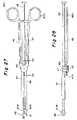
- FIG. 27is a side elevational view of the insertion instrument of FIG. 24 ;
- FIG. 28is a top plan view of FIG. 27 ;
- FIG. 29is a partial cross sectional view taken along line 29 - 29 of FIG. 27 ;
- FIG. 30is a top plan view of the spacer of FIG. 24 ;
- FIG. 31is a side elevational view of the spacer of FIG. 30 ;
- FIG. 32is a plan view of the bottom part of an implant with the spacer positioned thereon;
- FIG. 33is a side view of an implant with the spacer positioned therein;
- FIGS. 33A and 33Bare side views similar to FIG. 33 , but showing modifications.
- FIGS. 34-37show different steps in the operation of the insertion instrument of FIGS. 24-33 , wherein FIG. 37 is greatly enlarged relative to FIGS. 34-36 .
- FIGS. 1-4illustrate the implant constructed to be inserted using the instruments and in accordance with the method of the present invention.
- FIGS. 1 and 2illustrate an assembled intervertebral implant 210 including an upper part 211 and a lower part 230 and a plastic inlay 250 located therebetween but essentially connected to the lower part 230 .
- FIG. 3illustrates in detail the lower part 230 and
- FIG. 4illustrates in detail the plastic inlay 250 which is adapted to be connected to the lower part 230 in a manner to be described below.
- the upper part 211includes an upper surface 212 which engages and supports the adjacent vertebral surface.
- Upper surface 212is bounded by edges which are slightly beveled all the way around as shown at 213 with the largest portion of the bevel being shown along the front surface.
- Below the beveled edge 213the upper part is bounded by a surrounding side wall 214 which has a front support cutout 215 .
- the keels as discussed beloware shown oriented front to back, With the solid portion of the keels facing front and the insertion engaging recess facing rearwardly.
- a keel 216which includes a recess 217 formed therein. This recess is opened upwardly and rearwardly. Referring to FIG. 2 , this recess includes an indentation 221 in the base thereof.
- the front end of keel 216comprises a V-shaped upper bevel 219 . Referring to FIG. 1 , the lower portion of the front end of the keel is in the form of a V-shaped bevel 220 .
- the two V-shaped bevels 219 and 220provide a front end which is “arrow” shaped in order to facilitate insertion of the keel into a cutout formed in the adjacent vertebrae.
- the rear opening of the recessis flared at 218 to anchor the rear end of the keel 216 in its cutout in the adjacent vertebrae.
- the upper part 211includes a lower plane inner surface 224 which includes a raised rim 226 which defines a concave spherical portion 225 . This spherical portion 225 mates with an upper convex surface 252 of the plastic inlay 250 .
- the lower part 230includes a lower vertebrae supporting and engaging surface 231 and an inner upper surface 232 .
- This lower partincludes grooves 233 and 234 formed in the interior side wall thereof beneath surface 232 and above a base surface 238 .
- a substantially flat wall 235extends upwardly from the base surface 238 to the upper surface 232 .
- the lower part 230includes a back support cutout 237 .
- a keel 240rises upwardly (or in the usual orientation, extends downwardly) from lower surface 231 .
- This keelincludes a recess 241 which opens downwardly and rearwardly and has a flared entrance at 242 which serves the same function as flared entrance 218 , i.e., to facilitate engagement of the rear end of the keel within its cutout in the vertebrae.
- Recess 241opens downwardly and rearwardly and includes an indentation 243 .
- the keel 240includes a V-shaped lower bevel 245 and a V-shaped vertical portion (not shown) which together provide an “arrow” shaped front end to facilitate insertion of the keel into its cutout formed in the adjacent vertebrae.
- the plastic inlay 250includes a pair of side flanges 253 and 254 which slide into the grooves 233 and 234 in the lower part.
- the bottom of the plastic inlay 250may include a projection (visible in FIG. 2 ) which snaps into place in the recess 244 formed in the base surface 238 when the plastic inlay 250 is inserted into the lower part 230 .
- the intervertebral implant shown in FIG. 1-4 and to be inserted by the instruments and method of the present inventionhas been designed primarily for insertion in the cervical spine. When viewed in plan view, this implant would be approximately 12-16 mm in width and approximately 15-19 mm in length. It has been found practical to provide three different sizes, 15 mm ⁇ 19 mm, 14 mm ⁇ 17 mm and 16 mm ⁇ 19 mm.
- the height of the implantmeaning the height from the upper surface 212 of the upper part to the lower surface 231 of the lower part, would normally be between 5 mm and 9 mm. While this implant has been designed especially for application to the more delicate smaller cervical spine, the principles described herein are also applicable to intervertebral implants of a different size and design, such as for use in the lumbar spine.
- the upper and lower partsare made of a suitable material such as titanium, cobalt chromium molybdenum, stainless steel or ceramics.
- the upper surface of the upper part and the lower surface of the lower part as well as the side surfaces of the keelsare coated with a porous coating of titanium.
- the porosity of the coatingideally permits vascularization and osteoplast formation with subsequent bony on-growth.
- trial implantsare inserted into the intervertebral space to determine which trial implant is the correct one, thereby determining the size of the implant which is to be inserted therein.
- Trial implants for the cervical spinemay be provided in three different surface areas, i.e., when viewed in plan view, to match the three basic sizes of the implants, i.e., 12 mm ⁇ 15 mm, 14 mm ⁇ 17 mm and 16 mm ⁇ 19 mm. Each of these three surface areas could then be provided in five different heights from 5 mm to 9 mm, inclusive, thus providing a set of 15 trial implants. Cutouts would then be formed in the adjacent vertebrae to receive the keels.
- Insertion instruments and methods of the present inventionare then used for inserting the implant into the intervertebral space.
- FIG. 5is an anterior view of a pair of adjacent vertebrae V on opposite sides of a cleaned out intervertebral space I.
- cutouts Cwill have been formed. As shown in FIG. 6 , these cutouts start from the anterior of the vertebrae and extend for most but not all of the distance towards the posterior of the vertebrae, each intersecting along its entire length with the surface of the vertebrae facing into the intervertebral space. If formed by a chisel, the posterior end may either be neutral or angled back as shown at line D.
- the depth of the cutouts C into the vertebrae Vis established by the precisely controlled depth of a cutting tool.
- FIG. 6illustrates just to the right of the prepared adjacent vertebrae the intervertebral implant assembled and ready to be inserted, and to the right thereof is a schematic representation of a portion of an insertion instrument 90 .
- the insertion instrumentincludes upper and lower arms 91 A and 91 B which are arranged to move towards and away from each other as indicated by arrows B in FIG. 6 .
- One mechanism for moving the arms toward and away from each otheris a crossed linkage 98 which is partially shown in FIG. 7 .
- the upper and lower arms 91 A and 91 Binclude narrow keel engaging portions 92 A and 92 B which engage the recesses 217 and 241 , respectively.
- These armsinclude towards their outer ends projections 93 A and 93 B which are constructed to be received in indentations 221 and 243 , respectively. It will be noted that these keel engaging portions 92 A and 92 B are relatively narrow. In fact, it is contemplated that the entire width of each keel will be approximately 2 mm, thus allowing less than 2 mm for the actual recesses.
- the arms 91 A and 91 Balso include lateral support surfaces 94 A and 94 B which, upon engagement of the instrument with the implant, will engage the front support cutouts 215 and 237 .
- the arms 91 A and 91 Bwill be spaced apart just enough for the projections 93 A and 93 B to clear the bottoms of the recesses 217 and 241 until these projections reach the indentations 221 and 243 , at which time the arms 91 A and 91 B will be moved towards each other such that the projections engage within the indentations and the lateral support surfaces 94 A and 94 B are engaged within the cutouts 215 and 237 .
- abutment surfaces 95 A and 95 B on the upper and lower arms 91 A and 91 B respectivelywill abut each other, thus limiting further movement of the arms 91 A and 91 B towards each other.
- the implantis held in a suitable manner and the arms 92 A and 92 B are spread apart, moved in to the recesses 217 , 241 , and closed together such that the projections 93 A and 93 B engage indentations 221 and 243 .
- the implantcan be placed on the lower arm, with arm 92 B within recess 241 and projection 93 B in indentation 223 , after which the upper arm 92 A can be brought down into recess 217 with projection 93 A entering indentation 221 .
- the insertion instrumentmoves the entire implant into the intervertebral space I with the keels 216 and 240 entering the cutouts C while the surfaces 212 and 231 posterior to and adjacent to the keels engage the adjacent vertebral surfaces.
- FIG. 8there is a space above and below the arms 91 A and 91 B within the keel recesses 217 and 241 , the vertical dimension of which spaces is greater than the height of the projections 93 A and 93 B, which would normally be about 1.2 mm.
- Thisis necessary so that the arms 91 A and 91 B can be moved upwardly and downwardly, respectively, away from the base of their respective recesses to free the projections from their respective indentations before the upper and lower arms 91 A and 91 B can move horizontally out of the cutouts, without engaging the vertebrae at the vertical extremities of the cutouts C.
- the arms 91 A and 91 Bcan then be moved out anteriorly from the implant, leaving the implant in place as shown in FIG. 9 .
- FIGS. 10-16show a first embodiment of an insertion instrument.
- This crossed linkage instrument insertion instrumentincludes a body 3 having a control knob 4 at the rear end thereof and arms 1 and 2 at the forward end thereof. There is shown forward of these arms 1 and 2 , the arms 91 A and 91 B of the insertion instrument which is shown in FIGS. 6 , 7 and 8 , with an assembled implant 210 being held thereby.
- FIG. 11shows the insertion instrument with the arms 1 and 2 in the closed position holding the implant 210 .
- FIG. 11which shows the insertion instrument in the closed position
- FIGS. 14 and 15which show the insertion instrument in the opened position
- the mechanism for raising the arm 1includes crossed linkage comprising a first link 5 having a pivot pin 6 at one end thereof and a pivot pin 7 at the other end thereof.
- a second link 8has a pivot pin 9 at one end thereof and a second pin 10 at the opposite end thereof.
- a third link 11is connected at one end to second link 8 by means of a pivot pin 10 and at its other end to a sleeve 13 by means of a pivot pin 12 .
- Sleeve 13is in turn attached to a threaded rod 15 which is attached at pin 16 to a square cross section rod 17 which is slidably received in square opening 18 in the knob 4 .
- a spring 19rests against a shoulder in the body 3 and urges the rods 15 and 16 to the left, i.e., to the opened position of the arms.
- the insertion instrument of FIGS. 10-16operates as follows. Referring to FIGS. 12 and 13 , the threaded rod 15 engages a bevel washer 14 which is held in a space between the right hand end of lower arm 2 (Which at its far right hand end extends upwardly to cover virtually the entire circumference of the tool) and the left hand end of body portion 3 . To open the instrument, i.e., to move from the position of FIGS. 10 and 11 to the position of FIGS. 14 and 15 , the knob 4 is turned. The square recess 18 engages the square shaft 17 , turning it and thus via pin 16 , turning the threaded rod 15 . This causes the rod 15 to move to the left via its threaded engagement with the bevel washer 14 .
- FIGS. 17 and 18illustrate another embodiment 25 of a crossed linkage insertion instrument.
- This insertion instrumentis similar to the insertion instrument of FIGS. 10-16 with the exception of a circular knob 26 at the right hand end thereof and the thread engaging mechanism which is shown in greater detail in FIG. 18 .
- FIGS. 17 and 18elements which are identical to those shown in FIGS. 10-16 are represented by the same numerals.
- the bevel washer 14is replaced by a tapered washer or nut 27 .
- the taperfrictionally engages a conical wall 28 formed on the right hand end of lower arm 2 .
- the conical portion of nut 27frictionally engages the conical surface 28 which prevents the nut 27 from rotating, whereby the threaded rod 15 is threaded through the nut 27 to move the sleeve 13 and hence the link 11 to the left to move the upper arm 1 upwardly in the same manner as described above with respect to the embodiment of FIGS. 35-39 .
- FIGS. 19-22show another embodiment 30 of an insertion instrument.
- This embodimentis extremely simple and hence economical.
- this insertion instrument 30comprises a plastic body 31 having a front part 32 formed integrally with body 31 and comprising upper and lower arms 33 and 34 .
- insertion instrument 30is shown in its closed position holding an implant 210 .
- FIGS. 20 and 21illustrate the front portion 32 of the insertion instrument 30 .
- FIG. 20shows a thumb slide 35 and a pin 36 while in FIG. 21 part of the side wall and the thumb slide 35 are removed, thus revealing the pin 38 which would be attached to the thumb slide 35 and the rod 37 which engages a pin 36 .
- the two arms 33 and 34are normally urged resiliently towards each other to a closed implant holding position.
- the pin 36rides out of its recess 39 and urges the arms 33 and 34 apart, thus opening the insertion instrument.
- Attaching the implant to the instrument of FIGS. 19-22 and inserting the implant into the intervertebral spaceis essentially the same as described above with respect to FIGS. 5-9 .
- FIG. 23illustrates another embodiment of an insertion instrument.
- This embodiment 40is similar to the embodiment 30 of FIGS. 19-22 except that it is even more highly simplified.
- Forward of a body 41is a front part 40 which comprises at the outer end thereof upper and lower arms 42 and 43 which are of a resilient material and in their rest state are spread apart as shown in FIG. 23 .
- This embodimentincludes no separate mechanism for separating the arms 42 and 43 from each other.
- To attach the implant to the instrument of FIG. 23one would move the upper part of the implant about the spherical surface of plastic inlay 250 as shown in FIG.
- arms 42 and 43are then moved into the recesses until the projections 93 A and 93 B move into the indentations 221 and 243 and the top part rotates back to its correct position. As the top part rotates back to its correct position, the arms 42 and 43 are moved farther apart, thus creating the resilient force in the arms to secure them onto the implant.
- the insertion instrument 40is made with a degree of resilience such that the insertion instrument 40 can simply be pulled out of the inserted implant, whereupon the projections 93 A and 93 B will simply ride up out of their respective indentations 221 and 243 without harm to the inserted implant.
- the implantwill then be held with a very strong force by the adjacent vertebrae such that the force of removing the instrument 40 will be relatively small by comparison such that the projections 93 A and 93 B can easily ride up out of their respective indentations, as described above.
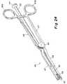
- FIGS. 24 and 25there is shown in perspective view an entire insertion instrument 45 and an enlarged view of the forward end thereof, respectively.
- This insertion instrumentincludes a first arm 46 and a second arm 47 , which arms are mounted on a common pivot in the manner of a scissors, which pivot is in the area of securing nut 65 , as described in greater detail below.
- a spacer tube 55runs the length of the instrument from a knob 57 at its rear end to an open end 56 at its opposite, forward end.
- the two arms 46 and 47are essentially coplanar rearward of the pivot connection and to one side of the spacer tube. These two arms then bend laterally in the vicinity of the pivot connection such that they become coplanar with the spacer tube 55 forward of their pivot connections.
- each of the arms 46 and 47have a narrow keel engaging end 50 and 48 , respectively, each of which has at its end a projection 51 and 49 , respectively, which engages the recesses 243 and 221 in the implants, respectively.
- Arm 47has a generally flat spacer engaging member 47 B and arm 46 has a similar generally flat spacer engaging member 46 B.
- this insertion instrumentincludes a spacer 60 with an enlarged spacer head 70 and a shaft 71 which is removably secured in the spacer tube 55 .
- the purpose of making the spacer removableis so that different size spacers can be utilized for different size implants.
- FIGS. 26A and 26Bshow the two arms 47 and 46 , respectively, separated from each other.
- the arm 47includes a thumb/finger grip portion 47 A, a central flat circular portion 46 C and the previously described flat spacer engaging member 47 B. This end, including narrow forward end 48 and member 47 B engage the implant and the spacer from above.
- FIG. 26Bshows the other arm 46 which includes portions similar to those of arm 47 including a thumb/finger grip portion 46 A, a flat circular central portion 46 C and a forward end including a narrow forward end 50 and a lower flat spacer engaging member 46 B, wherein the members 46 B and 50 engage the implant and spacer from below.
- the ridged locking flange 48 Dincludes ridges on the opposite side thereof which, when lowered onto ridges 47 D will lock the two arms together.
- the insertion instrument 45is made by placing the two circular flat portions 46 C and 47 C against each other with the portion 47 C closest to the securing nut 65 and the portion 46 C closest to the tube 55 , as best shown in FIG. 29 .
- the two flat central portions 46 C and 47 Care secured together by a securing nut 65 and a shaft 66 which passes threrethrough, through the openings in the flat central portions 46 C and 47 C and includes at the other end thereof a sleeve 67 which fixedly secures the forward and rear sections of the fixed spacer tube 55 .
- the two arms 46 and 47are generally coplanar, as viewed from above, toward the rear of their pivot connection, they both bend toward the spacer tube 55 so that the forward ends of both arms, as viewed from above, are generally coplanar with the spacer tube 55 .
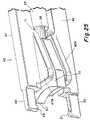
- FIGS. 30 and 31illustrate a spacer 60 .
- the spacerincludes an enlarged head 70 and a shaft 71 .
- the shaftis made of a bent resilient material having sufficient resiliency that when the shaft 71 is inserted into the end 56 of spacer tube 55 , the resiliency of shaft 71 will cause it to be secured within the spacer tube 55 .
- the spacer head 70includes projections 72 and 73 on the top and bottom thereof, respectively. These engage dimpled recesses 74 and 75 in members 47 B and 46 B, respectively, in order to positively position the spacer head 70 and hence the spacer itself in position between the members 47 B and 46 B, when they are closed against the spacer.
- FIGS. 32 and 33illustrate the position of the spacer 60 in its fully operative position wherein the arms 46 and 47 would be in their closed position securing the implant 210 .
- the spacer 60would rest on the very small ledge of the lower part just rearward of the plastic inlay 250 while the upper edge of spacer 60 would engage the bottom rearwardmost surface of the upper part, rearward of the raised rim 226 , to thereby prevent the rear of the upper and lower parts from rotating about the plastic inlay 50 any closer to each other than permitted by the spacer 60 .
- FIGS. 33A and 33Bshow how the spacer can be used to create anatomical angulation. In FIG. 33A , a thinner spacer 60 is used to create a kyphosis angle while in FIG. 33B a thicker spacer 60 is used to crease a lordosis angle.
- the various insertion instrumentsmay be used to insert the implant.
- the knob 4is turned to move the arms 1 and 2 away from each other (actually moving the arm 1 upwardly away from the arm 2 which is fixed with respect to the body 3 ).
- the assembled implantis then placed between the arms 1 and 2 , and more specifically, between the keel engaging portions 91 A and 91 B thereof, as described above, and the crossed linkage mechanism is closed.
- the crossed linkage mechanismis closed.
- this free movement to the right, to the closing positionis permitted because a beveled washer engages the threaded rod and prevents its free movement to the left, i.e., to the open position of the scissors linkage.
- a conical nutwhich meets frictional resistance and thus causes threaded movement of the threaded rod to the left, to the open position, but moves to a friction-free position to permit free movement of the threaded rod to the right upon downward pressure applied to the upper arm 1 to move the crossed linkage to the closed, implant engaging position.
- the two arms 1 and 2would then be moved apart in the manner described above, just enough to free the projections 93 A and 93 B from the indentations 221 and 243 , after which the insertion instrument would be moved rearwardly out of the implant, leaving the implant in place.
- the method of operating the insertion instrument of FIG. 23would differ slightly from the method of operating the insertion instrument of FIGS. 19-22 .
- the insertion instrument of FIG. 23there is no thumb slide, no recess 39 and no pin 36 .
- the operatorwould insert a slightly inclined implant, as shown in FIG. 23A , between the arms 33 and 34 to permit the ends of these arms to move into the keel recesses until the projections 93 A and 93 B reached and engaged the respective indentations 221 and 243 .
- the insertion instrument of FIG. 23would be removed by physically pulling the arms 33 and 34 out of the implant.
- the correct size implantwill have been determined by the use of trial implants.
- the resilient shaft 71 of the correct size spacer 60is inserted into the open end 56 of the tube 55 and moved all the way in until the collar 76 fits snuggly within the end of the tube 55 , wherein the resilient bending of shaft 71 secures this spacer in place in the tube.
- the bottom part 230 of the implantis positioned on the arm 46 , and specifically, on the forward narrow end 50 such that its projection 51 engages the recess 243 in the keel 240 .
- the forward end of spacer 60is placed against the rear of the lower part as shown in FIG.
- the upper part 211 of the implantis placed onto the upper arm 47 , and specifically the narrow front end 48 thereof such that the projection 49 engages the recess 221 in the keel 216 .
- a narrower or thicker spacer 60may be used to create a kyphosis angle or a lordosis angle, respectively.
- the insertion instrumentis now moved to bring the implant 210 into the intervertebral space, with the keels 216 and 240 entering the cutouts C, as discussed with respect to earlier embodiments and as described with respect to FIGS. 5 , 6 , 8 and 9 .
- the spacer 60 and its facing surfaces of members 46 B and 47 Bare secured relative to each other by engagement of the projections 72 and 73 into recesses 74 and 75 , respectively.
Landscapes
- Health & Medical Sciences (AREA)
- Engineering & Computer Science (AREA)
- Biomedical Technology (AREA)
- Orthopedic Medicine & Surgery (AREA)
- Transplantation (AREA)
- Life Sciences & Earth Sciences (AREA)
- Veterinary Medicine (AREA)
- Public Health (AREA)
- General Health & Medical Sciences (AREA)
- Animal Behavior & Ethology (AREA)
- Heart & Thoracic Surgery (AREA)
- Vascular Medicine (AREA)
- Oral & Maxillofacial Surgery (AREA)
- Cardiology (AREA)
- Neurology (AREA)
- Physical Education & Sports Medicine (AREA)
- Surgery (AREA)
- Nuclear Medicine, Radiotherapy & Molecular Imaging (AREA)
- Medical Informatics (AREA)
- Molecular Biology (AREA)
- Prostheses (AREA)
Abstract
Description
Claims (13)
Priority Applications (12)
| Application Number | Priority Date | Filing Date | Title |
|---|---|---|---|
| US10/622,535US7803162B2 (en) | 2003-07-21 | 2003-07-21 | Instruments and method for inserting an intervertebral implant |
| JP2006521118AJP2006528029A (en) | 2003-07-21 | 2004-07-14 | Instruments and methods for inserting intervertebral implants |
| PCT/US2004/022608WO2005009485A2 (en) | 2003-07-21 | 2004-07-14 | Instruments and method for inserting an intervertebral implant |
| EP04778217.2AEP1653870B1 (en) | 2003-07-21 | 2004-07-14 | Instruments for inserting an intervertebral implant |
| CA002534640ACA2534640A1 (en) | 2003-07-21 | 2004-07-14 | Instruments and method for inserting an intervertebral implant |
| AU2004258906AAU2004258906A1 (en) | 2003-07-21 | 2004-07-14 | Instruments and method for inserting an intervertebral implant |
| KR1020067001439AKR20060037388A (en) | 2003-07-21 | 2004-07-14 | Intervertebral Implant Insertion Apparatus and Method |
| CNA2004800238423ACN1838916A (en) | 2003-07-21 | 2004-07-14 | Instrument and method for inserting an intervertebral implant |
| BRPI0412774-9ABRPI0412774A (en) | 2003-07-21 | 2004-07-14 | instrument for inserting an intervertebral implant into an intervertebral space, and method for inserting an intervertebral implant into an intervertebral space |
| ZA200600337AZA200600337B (en) | 2003-07-21 | 2006-01-06 | Instruments and method for inserting an intervertebal implant |
| CO06004166ACO5640062A1 (en) | 2003-07-21 | 2006-01-18 | INSTRUMENTS AND METHODS TO INSERT AN INTERVERTEBRAL IMPLANT |
| US12/878,101US8349017B2 (en) | 2003-07-21 | 2010-09-09 | Instruments and method for inserting an intervertebral implant |
Applications Claiming Priority (1)
| Application Number | Priority Date | Filing Date | Title |
|---|---|---|---|
| US10/622,535US7803162B2 (en) | 2003-07-21 | 2003-07-21 | Instruments and method for inserting an intervertebral implant |
Related Child Applications (1)
| Application Number | Title | Priority Date | Filing Date |
|---|---|---|---|
| US12/878,101DivisionUS8349017B2 (en) | 2003-07-21 | 2010-09-09 | Instruments and method for inserting an intervertebral implant |
Publications (2)
| Publication Number | Publication Date |
|---|---|
| US20050021042A1 US20050021042A1 (en) | 2005-01-27 |
| US7803162B2true US7803162B2 (en) | 2010-09-28 |
Family
ID=34079759
Family Applications (2)
| Application Number | Title | Priority Date | Filing Date |
|---|---|---|---|
| US10/622,535Active2026-04-02US7803162B2 (en) | 2003-07-21 | 2003-07-21 | Instruments and method for inserting an intervertebral implant |
| US12/878,101Expired - Fee RelatedUS8349017B2 (en) | 2003-07-21 | 2010-09-09 | Instruments and method for inserting an intervertebral implant |
Family Applications After (1)
| Application Number | Title | Priority Date | Filing Date |
|---|---|---|---|
| US12/878,101Expired - Fee RelatedUS8349017B2 (en) | 2003-07-21 | 2010-09-09 | Instruments and method for inserting an intervertebral implant |
Country Status (11)
| Country | Link |
|---|---|
| US (2) | US7803162B2 (en) |
| EP (1) | EP1653870B1 (en) |
| JP (1) | JP2006528029A (en) |
| KR (1) | KR20060037388A (en) |
| CN (1) | CN1838916A (en) |
| AU (1) | AU2004258906A1 (en) |
| BR (1) | BRPI0412774A (en) |
| CA (1) | CA2534640A1 (en) |
| CO (1) | CO5640062A1 (en) |
| WO (1) | WO2005009485A2 (en) |
| ZA (1) | ZA200600337B (en) |
Cited By (32)
| Publication number | Priority date | Publication date | Assignee | Title |
|---|---|---|---|---|
| US20060058808A1 (en)* | 2004-09-08 | 2006-03-16 | Susanne Schneid | Surgical instrument |
| US20070123907A1 (en)* | 2004-07-28 | 2007-05-31 | Weber Instrumente Gmbh | Surgical instrument for the introduction of a multi-component intervertebral prosthesis |
| US20080027553A1 (en)* | 1997-01-02 | 2008-01-31 | Zucherman James F | Spine distraction implant and method |
| US20100094422A1 (en)* | 2008-10-13 | 2010-04-15 | Noah Hansell | Intervertebral Spacer |
| US20100298941A1 (en)* | 2009-05-19 | 2010-11-25 | Robert Hes | Dynamic trial implants |
| US20100324690A1 (en)* | 2007-03-14 | 2010-12-23 | Heather Cannon | Intervertebral Implant Component With Three Points of Contact |
| US20100331988A1 (en)* | 2003-07-21 | 2010-12-30 | Theirry Marnay | Instruments and Method For Inserting An Intervertebral Implant |
| US7896919B2 (en)* | 2003-08-04 | 2011-03-01 | Zimmer Spine S.A.S. | Method of implanting intervertebral disk prosthesis |
| US20110066192A1 (en)* | 2009-09-15 | 2011-03-17 | William Frasier | Expandable Ring Intervertebral Fusion Device |
| US20110066244A1 (en)* | 2009-09-11 | 2011-03-17 | William Frasier | Minimally Invasive Intervertebral Staple Distraction Devices |
| US20110077652A1 (en)* | 2009-01-08 | 2011-03-31 | Philippe Bellemere | Intramedullary anchoring stem for an orthopaedic implant head |
| US8142441B2 (en)* | 2008-10-16 | 2012-03-27 | Aesculap Implant Systems, Llc | Surgical instrument and method of use for inserting an implant between two bones |
| US8337500B2 (en) | 2006-07-31 | 2012-12-25 | Synthes Usa, Llc | Drilling/milling guide and keel cut preparation system |
| US8500749B2 (en)* | 2011-04-19 | 2013-08-06 | Prescient Surgical Designs, Llc | Apparatus and method for inserting intervertebral implants |
| US8562681B2 (en) | 2012-01-31 | 2013-10-22 | Styker Spine | Laminoplasty implant, method and instrumentation |
| US8858644B2 (en) | 2009-01-08 | 2014-10-14 | Memometal Technologies | Orthopaedic implant for arthroplasty of the fingers |
| US8882839B2 (en) | 1999-07-02 | 2014-11-11 | DePuy Synthes Products, LLC | Intervertebral implant |
| US8998990B2 (en) | 2006-07-24 | 2015-04-07 | DePuy Synthes Products, LLC | Intervertebral implant with keel |
| US9034046B2 (en) | 2007-10-30 | 2015-05-19 | Aesculap Implant Systems, Llc | Vertebral body replacement device and method for use to maintain a space between two vertebral bodies within a spine |
| US20150245924A1 (en)* | 2006-11-28 | 2015-09-03 | Spineart Sa | Prosthesis holder and application thereof |
| US9259327B2 (en) | 2008-10-13 | 2016-02-16 | Globus Medical, Inc. | Articulating spacer |
| US9301854B2 (en) | 2005-04-12 | 2016-04-05 | Ahmnon D. Moskowitz | Bi-directional fixating transvertebral body screws and posterior cervical and lumbar interarticulating joint calibrated stapling devices for spinal fusion |
| US9452060B2 (en)* | 2011-02-23 | 2016-09-27 | Globus Medical, Inc. | Six degree spine stabilization devices and methods |
| US9532821B2 (en) | 2005-04-12 | 2017-01-03 | Nathan C. Moskowitz | Bi-directional fixating/locking transvertebral body screw/intervertebral cage stand-alone constructs with vertical hemi-bracket screw locking mechanism |
| US9744052B2 (en) | 2005-04-12 | 2017-08-29 | Nathan C. Moskowitz | Bi-directional fixating/locking transvertebral body screw/intervertebral cage stand-alone constructs |
| US9814601B2 (en) | 2005-04-12 | 2017-11-14 | Nathan C. Moskowitz | Bi-directional fixating/locking transvertebral body screw/intervertebral cage stand-alone constructs |
| US9848993B2 (en) | 2005-04-12 | 2017-12-26 | Nathan C. Moskowitz | Zero-profile expandable intervertebral spacer devices for distraction and spinal fusion and a universal tool for their placement and expansion |
| US10004609B2 (en) | 2016-09-23 | 2018-06-26 | Warsaw Orthopedic, Inc. | Surgical instrument and method |
| US10076367B2 (en) | 2005-04-12 | 2018-09-18 | Moskowitz Family Llc | Bi-directional fixating transvertebral body screws, zero-profile horizontal intervertebral miniplates, total intervertebral body fusion devices, and posterior motion-calibrating interarticulating joint stapling device for spinal fusion |
| US10182831B2 (en) | 2003-04-28 | 2019-01-22 | Centinel Spine Llc | Instruments and method for preparing an intervertebral space for receiving an artificial disc implant |
| US20210106437A1 (en)* | 2004-08-06 | 2021-04-15 | Simplify Medical Pty Ltd | Methods and apparatus for intervertebral disc prosthesis insertion |
| US11903849B2 (en) | 2005-04-12 | 2024-02-20 | Moskowitz Family Llc | Intervertebral implant and tool assembly |
Families Citing this family (137)
| Publication number | Priority date | Publication date | Assignee | Title |
|---|---|---|---|---|
| US20030055502A1 (en) | 2001-05-25 | 2003-03-20 | Philipp Lang | Methods and compositions for articular resurfacing |
| US20090222103A1 (en)* | 2001-05-25 | 2009-09-03 | Conformis, Inc. | Articular Implants Providing Lower Adjacent Cartilage Wear |
| US8556983B2 (en) | 2001-05-25 | 2013-10-15 | Conformis, Inc. | Patient-adapted and improved orthopedic implants, designs and related tools |
| US20110071802A1 (en)* | 2009-02-25 | 2011-03-24 | Ray Bojarski | Patient-adapted and improved articular implants, designs and related guide tools |
| US8480754B2 (en) | 2001-05-25 | 2013-07-09 | Conformis, Inc. | Patient-adapted and improved articular implants, designs and related guide tools |
| US8545569B2 (en) | 2001-05-25 | 2013-10-01 | Conformis, Inc. | Patient selectable knee arthroplasty devices |
| US8771365B2 (en)* | 2009-02-25 | 2014-07-08 | Conformis, Inc. | Patient-adapted and improved orthopedic implants, designs, and related tools |
| US9603711B2 (en)* | 2001-05-25 | 2017-03-28 | Conformis, Inc. | Patient-adapted and improved articular implants, designs and related guide tools |
| US8617242B2 (en) | 2001-05-25 | 2013-12-31 | Conformis, Inc. | Implant device and method for manufacture |
| US8882847B2 (en)* | 2001-05-25 | 2014-11-11 | Conformis, Inc. | Patient selectable knee joint arthroplasty devices |
| US20110071645A1 (en)* | 2009-02-25 | 2011-03-24 | Ray Bojarski | Patient-adapted and improved articular implants, designs and related guide tools |
| US8735773B2 (en) | 2007-02-14 | 2014-05-27 | Conformis, Inc. | Implant device and method for manufacture |
| EP1792586B1 (en) | 1999-09-14 | 2012-12-26 | Spine Solutions Inc. | Insert instrument for an implant between vertebrae |
| FR2824261B1 (en)* | 2001-05-04 | 2004-05-28 | Ldr Medical | INTERVERTEBRAL DISC PROSTHESIS AND IMPLEMENTATION METHOD AND TOOLS |
| AR038680A1 (en) | 2002-02-19 | 2005-01-26 | Synthes Ag | INTERVERTEBRAL IMPLANT |
| US20080027548A9 (en) | 2002-04-12 | 2008-01-31 | Ferree Bret A | Spacerless artificial disc replacements |
| US8038713B2 (en) | 2002-04-23 | 2011-10-18 | Spinecore, Inc. | Two-component artificial disc replacements |
| US6706068B2 (en) | 2002-04-23 | 2004-03-16 | Bret A. Ferree | Artificial disc replacements with natural kinematics |
| US8388684B2 (en) | 2002-05-23 | 2013-03-05 | Pioneer Signal Technology, Inc. | Artificial disc device |
| US7001433B2 (en)* | 2002-05-23 | 2006-02-21 | Pioneer Laboratories, Inc. | Artificial intervertebral disc device |
| JP2006501977A (en)* | 2002-10-07 | 2006-01-19 | コンフォーミス・インコーポレイテッド | Minimally invasive joint implant with a three-dimensional profile that conforms to the joint surface |
| FR2846550B1 (en)* | 2002-11-05 | 2006-01-13 | Ldr Medical | INTERVERTEBRAL DISC PROSTHESIS |
| JP2006505366A (en) | 2002-11-07 | 2006-02-16 | コンフォーミス・インコーポレイテッド | Method of determining meniscus size and shape and devised treatment |
| US7204852B2 (en) | 2002-12-13 | 2007-04-17 | Spine Solutions, Inc. | Intervertebral implant, insertion tool and method of inserting same |
| CA2515247C (en) | 2003-02-06 | 2010-10-05 | Synthes (U.S.A.) | Intervertebral implant |
| US6908484B2 (en) | 2003-03-06 | 2005-06-21 | Spinecore, Inc. | Cervical disc replacement |
| DE20310433U1 (en)* | 2003-07-08 | 2003-09-04 | Aesculap AG & Co. KG, 78532 Tuttlingen | Surgical device for inserting dual component implant into appropriate space at spine, comprising particularly shaped holding area |
| US7153325B2 (en)* | 2003-08-01 | 2006-12-26 | Ultra-Kinetics, Inc. | Prosthetic intervertebral disc and methods for using the same |
| US8123757B2 (en)* | 2003-12-31 | 2012-02-28 | Depuy Spine, Inc. | Inserter instrument and implant clip |
| FR2865629B1 (en)* | 2004-02-04 | 2007-01-26 | Ldr Medical | INTERVERTEBRAL DISC PROSTHESIS |
| EP2113227B1 (en) | 2004-02-04 | 2015-07-29 | LDR Medical | Intervertebral disc prosthesis |
| FR2869528B1 (en)* | 2004-04-28 | 2007-02-02 | Ldr Medical | INTERVERTEBRAL DISC PROSTHESIS |
| US8128662B2 (en) | 2004-10-20 | 2012-03-06 | Vertiflex, Inc. | Minimally invasive tooling for delivery of interspinous spacer |
| US8317864B2 (en) | 2004-10-20 | 2012-11-27 | The Board Of Trustees Of The Leland Stanford Junior University | Systems and methods for posterior dynamic stabilization of the spine |
| US9119680B2 (en) | 2004-10-20 | 2015-09-01 | Vertiflex, Inc. | Interspinous spacer |
| US8152837B2 (en) | 2004-10-20 | 2012-04-10 | The Board Of Trustees Of The Leland Stanford Junior University | Systems and methods for posterior dynamic stabilization of the spine |
| US8167944B2 (en) | 2004-10-20 | 2012-05-01 | The Board Of Trustees Of The Leland Stanford Junior University | Systems and methods for posterior dynamic stabilization of the spine |
| US8273108B2 (en) | 2004-10-20 | 2012-09-25 | Vertiflex, Inc. | Interspinous spacer |
| US8597360B2 (en) | 2004-11-03 | 2013-12-03 | Neuropro Technologies, Inc. | Bone fusion device |
| US20060149284A1 (en)* | 2004-12-15 | 2006-07-06 | Sdgi Holdings, Inc. | Insertion device and method for inserting a member within the body |
| FR2879436B1 (en)* | 2004-12-22 | 2007-03-09 | Ldr Medical | INTERVERTEBRAL DISC PROSTHESIS |
| AU2012202443B2 (en)* | 2005-05-27 | 2014-04-10 | Spinecore, Inc. | Intervertebral disc and insertion methods therefor |
| US8777959B2 (en)* | 2005-05-27 | 2014-07-15 | Spinecore, Inc. | Intervertebral disc and insertion methods therefor |
| US8394142B2 (en)* | 2005-06-13 | 2013-03-12 | Synthes Usa, Llc | Customizing an intervertebral implant |
| FR2887762B1 (en) | 2005-06-29 | 2007-10-12 | Ldr Medical Soc Par Actions Si | INTERVERTEBRAL DISC PROSTHESIS INSERTION INSTRUMENTATION BETWEEN VERTEBRATES |
| CA2621019A1 (en)* | 2005-08-31 | 2007-03-08 | Zimmer Gmbh | Implant |
| FR2891135B1 (en) | 2005-09-23 | 2008-09-12 | Ldr Medical Sarl | INTERVERTEBRAL DISC PROSTHESIS |
| US7618459B2 (en)* | 2005-09-26 | 2009-11-17 | Infinity Orthopedics Ltd. | Universal spinal disc implant system |
| US8696681B2 (en)* | 2005-09-29 | 2014-04-15 | K2M, Inc. | Adjustable interbody introducer device and method |
| EP1772106A1 (en) | 2005-10-06 | 2007-04-11 | Zimmer GmbH | Instrument for preparing and/or working the femur head |
| EP1973498B1 (en)* | 2005-11-09 | 2014-04-23 | Zimmer GmbH | Implant |
| WO2007062079A2 (en)* | 2005-11-21 | 2007-05-31 | Philipp Lang | Devices and methods for treating facet joints, uncovertebral joints, costovertebral joints and other joints |
| EP1951136A1 (en)* | 2005-11-23 | 2008-08-06 | Conformis, Inc. | Implant grasper |
| FR2893838B1 (en)* | 2005-11-30 | 2008-08-08 | Ldr Medical Soc Par Actions Si | PROSTHESIS OF INTERVERTEBRAL DISC AND INSTRUMENTATION OF INSERTION OF THE PROSTHESIS BETWEEN VERTEBRATES |
| CN105030296A (en)* | 2006-02-06 | 2015-11-11 | 康复米斯公司 | Patient selectable joint arthroplasty devices and surgical tools |
| WO2007090790A2 (en)* | 2006-02-09 | 2007-08-16 | Zimmer Gmbh | Implant |
| EP1988855A2 (en) | 2006-02-27 | 2008-11-12 | Synthes GmbH | Intervertebral implant with fixation geometry |
| US7875034B2 (en)* | 2006-03-14 | 2011-01-25 | Warsaw Orthopedic, Inc. | Spinal disc space preparation instruments and methods for interbody spinal implants |
| WO2007125060A1 (en)* | 2006-04-28 | 2007-11-08 | Zimmer Gmbh | Implant |
| US8303601B2 (en)* | 2006-06-07 | 2012-11-06 | Stryker Spine | Collet-activated distraction wedge inserter |
| US8062303B2 (en)* | 2006-08-16 | 2011-11-22 | K2M, Inc. | Apparatus and methods for inserting an implant |
| US8715350B2 (en) | 2006-09-15 | 2014-05-06 | Pioneer Surgical Technology, Inc. | Systems and methods for securing an implant in intervertebral space |
| WO2008034135A2 (en) | 2006-09-15 | 2008-03-20 | Pioneer Surgical Technology, Inc. | Joint arthroplasty devices having articulating members |
| US9381098B2 (en)* | 2006-09-28 | 2016-07-05 | Spinal Kinetics, Inc. | Tool systems for implanting prosthetic intervertebral discs |
| US8465546B2 (en) | 2007-02-16 | 2013-06-18 | Ldr Medical | Intervertebral disc prosthesis insertion assemblies |
| US20080228276A1 (en)* | 2007-03-14 | 2008-09-18 | Warsaw Orthopedic, Inc. | Intervertebral Prosthesis, Instruments, and Methods of Implanting |
| US8361080B2 (en)* | 2007-03-30 | 2013-01-29 | Depuy Spine, Inc. | Implant inserter having a bifurcated adjustable stop |
| AU2008241447B2 (en) | 2007-04-16 | 2014-03-27 | Vertiflex, Inc. | Interspinous spacer |
| US8579910B2 (en) | 2007-05-18 | 2013-11-12 | DePuy Synthes Products, LLC | Insertion blade assembly and method of use |
| FR2916956B1 (en)* | 2007-06-08 | 2012-12-14 | Ldr Medical | INTERSOMATIC CAGE, INTERVERTEBRAL PROSTHESIS, ANCHORING DEVICE AND IMPLANTATION INSTRUMENTATION |
| WO2009018128A2 (en)* | 2007-07-31 | 2009-02-05 | Zimmer, Inc. | Joint space interpositional prosthetic device with internal bearing surfaces |
| US8801758B2 (en)* | 2007-08-13 | 2014-08-12 | Stryker Spine | Insertion instrument for intervertebral implants |
| US20090088847A1 (en)* | 2007-10-01 | 2009-04-02 | Manoj Krishna | Surgical instrument system |
| WO2009055541A1 (en)* | 2007-10-23 | 2009-04-30 | K2M, Inc. | Implant insertion tool |
| JP2011502708A (en) | 2007-11-16 | 2011-01-27 | ジンテス ゲゼルシャフト ミット ベシュレンクテル ハフツング | Low profile intervertebral implant |
| US8241363B2 (en)* | 2007-12-19 | 2012-08-14 | Depuy Spine, Inc. | Expandable corpectomy spinal fusion cage |
| US8241294B2 (en)* | 2007-12-19 | 2012-08-14 | Depuy Spine, Inc. | Instruments for expandable corpectomy spinal fusion cage |
| WO2009089367A2 (en) | 2008-01-09 | 2009-07-16 | Providence Medical Technology, Inc. | Methods and apparatus for accessing and treating the facet joint |
| AU2009206098B2 (en) | 2008-01-15 | 2014-10-30 | Vertiflex, Inc. | Interspinous spacer |
| AU2009205679B2 (en) | 2008-01-18 | 2013-12-05 | Spinecore, Inc. | Instruments and methods for inserting artificial intervertebral implants |
| WO2009111626A2 (en) | 2008-03-05 | 2009-09-11 | Conformis, Inc. | Implants for altering wear patterns of articular surfaces |
| AU2009221773B2 (en)* | 2008-03-05 | 2015-03-05 | Conformis, Inc. | Edge-matched articular implant |
| US8449554B2 (en) | 2008-03-07 | 2013-05-28 | K2M, Inc. | Intervertebral implant and instrument with removable section |
| FR2929503B1 (en)* | 2008-04-08 | 2011-04-29 | Kiscomedica | JOINT PROSTHESIS THAT CAN BE IMPLANTED BETWEEN TWO BONES |
| WO2009140294A1 (en)* | 2008-05-12 | 2009-11-19 | Conformis, Inc. | Devices and methods for treatment of facet and other joints |
| US11224521B2 (en) | 2008-06-06 | 2022-01-18 | Providence Medical Technology, Inc. | Cervical distraction/implant delivery device |
| CA2725811A1 (en) | 2008-06-06 | 2009-12-10 | Providence Medical Technology, Inc. | Facet joint implants and delivery tools |
| US8382767B2 (en)* | 2008-10-31 | 2013-02-26 | K2M, Inc. | Implant insertion tool |
| CN102256570B (en) | 2008-11-07 | 2015-09-02 | 斯恩蒂斯有限公司 | Spacer and connecting plate assembly between vertebral bodies |
| WO2010075195A1 (en)* | 2008-12-22 | 2010-07-01 | Synthes Usa, Llc | Orthopedic implant with flexible keel |
| US9095450B2 (en)* | 2008-12-24 | 2015-08-04 | DePuy Syntheses Products, Inc. | Insertion instrument for anteriorly inserting intervertebral spinal implants |
| WO2010099231A2 (en) | 2009-02-24 | 2010-09-02 | Conformis, Inc. | Automated systems for manufacturing patient-specific orthopedic implants and instrumentation |
| US8906033B2 (en)* | 2009-03-30 | 2014-12-09 | DePuy Synthes Products, LLC | Cervical motion disc inserter |
| US8876905B2 (en)* | 2009-04-29 | 2014-11-04 | DePuy Synthes Products, LLC | Minimally invasive corpectomy cage and instrument |
| ATE542483T1 (en)* | 2009-07-17 | 2012-02-15 | Ulrich Gmbh & Co Kg | DISTRACTION ELEMENT FOR THE SPINE |
| CA2782137A1 (en)* | 2009-12-11 | 2011-06-16 | Conformis, Inc. | Patient-specific and patient-engineered orthopedic implants |
| US9301853B2 (en)* | 2010-04-09 | 2016-04-05 | DePuy Synthes Products, Inc. | Holder for implantation and extraction of prosthesis |
| US8858636B2 (en) | 2010-04-09 | 2014-10-14 | DePuy Synthes Products, LLC | Intervertebral implant |
| WO2012083101A1 (en) | 2010-12-17 | 2012-06-21 | Synthes Usa, Llc | Methods and systems for minimally invasive posterior arch expansion |
| WO2012088238A2 (en) | 2010-12-21 | 2012-06-28 | Synthes Usa, Llc | Intervertebral implants, systems, and methods of use |
| US9358122B2 (en) | 2011-01-07 | 2016-06-07 | K2M, Inc. | Interbody spacer |
| WO2012112694A2 (en) | 2011-02-15 | 2012-08-23 | Conformis, Inc. | Medeling, analyzing and using anatomical data for patient-adapted implants. designs, tools and surgical procedures |
| US9579214B1 (en)* | 2011-03-01 | 2017-02-28 | John W. McClellan | Peripheral vertebral body spacer implant and insertion tool |
| CN102670335A (en)* | 2011-03-11 | 2012-09-19 | 镱钛科技股份有限公司 | Spinal surgery tool |
| JP5663674B2 (en) | 2011-03-11 | 2015-02-04 | エフビーシー デバイス エーピーエス | Spine implant, pretreatment instrument and method of use |
| US8540721B2 (en) | 2011-04-04 | 2013-09-24 | Amicus Design Group, Llc | Adjustable apparatus and methods for inserting an implant |
| WO2013023096A1 (en) | 2011-08-09 | 2013-02-14 | Neuropro Technologies, Inc. | Bone fusion device, system and method |
| US10420654B2 (en) | 2011-08-09 | 2019-09-24 | Neuropro Technologies, Inc. | Bone fusion device, system and method |
| US9358123B2 (en) | 2011-08-09 | 2016-06-07 | Neuropro Spinal Jaxx, Inc. | Bone fusion device, apparatus and method |
| US9198769B2 (en) | 2011-12-23 | 2015-12-01 | Pioneer Surgical Technology, Inc. | Bone anchor assembly, bone plate system, and method |
| KR101373287B1 (en)* | 2012-04-04 | 2014-03-11 | (주) 서한케어 | Interspinous process spacer insertion holder |
| US10159583B2 (en)* | 2012-04-13 | 2018-12-25 | Neuropro Technologies, Inc. | Bone fusion device |
| US9532883B2 (en) | 2012-04-13 | 2017-01-03 | Neuropro Technologies, Inc. | Bone fusion device |
| EP2916777A1 (en)* | 2012-11-12 | 2015-09-16 | DePuy Synthes Products, Inc. | Interbody interference implant and instrumentation |
| CA2906531C (en) | 2013-03-15 | 2020-10-06 | Neuropro Technologies, Inc. | Bodiless bone fusion device, apparatus and method |
| US9730802B1 (en) | 2014-01-14 | 2017-08-15 | Nuvasive, Inc. | Spinal fusion implant and related methods |
| AU2015267055B2 (en) | 2014-05-27 | 2020-04-02 | Christopher U. Phan | Lateral mass fixation implant |
| US9867718B2 (en) | 2014-10-22 | 2018-01-16 | DePuy Synthes Products, Inc. | Intervertebral implants, systems, and methods of use |
| CN105266928B (en)* | 2015-09-29 | 2017-11-10 | 深圳清华大学研究院 | The method of cervical intervertebral disk prosthesis, implantation instrument, cervical intervertebral disk prosthesis and implantation instrument combination unit and utilization of cervical implants implantation cervical vertebra |
| US9655740B1 (en)* | 2016-04-28 | 2017-05-23 | Spine Wave, Inc. | Expandable sizer instrument for spacing vertebral bodies |
| US10111760B2 (en) | 2017-01-18 | 2018-10-30 | Neuropro Technologies, Inc. | Bone fusion system, device and method including a measuring mechanism |
| US10213321B2 (en) | 2017-01-18 | 2019-02-26 | Neuropro Technologies, Inc. | Bone fusion system, device and method including delivery apparatus |
| US10973657B2 (en) | 2017-01-18 | 2021-04-13 | Neuropro Technologies, Inc. | Bone fusion surgical system and method |
| US10729560B2 (en) | 2017-01-18 | 2020-08-04 | Neuropro Technologies, Inc. | Bone fusion system, device and method including an insertion instrument |
| US11871968B2 (en) | 2017-05-19 | 2024-01-16 | Providence Medical Technology, Inc. | Spinal fixation access and delivery system |
| WO2019051260A1 (en) | 2017-09-08 | 2019-03-14 | Pioneer Surgical Technology, Inc. | Intervertebral implants, instruments, and methods |
| USD907771S1 (en) | 2017-10-09 | 2021-01-12 | Pioneer Surgical Technology, Inc. | Intervertebral implant |
| US11648128B2 (en) | 2018-01-04 | 2023-05-16 | Providence Medical Technology, Inc. | Facet screw and delivery device |
| US10905566B2 (en)* | 2018-02-05 | 2021-02-02 | Spineology Inc. | Percutaneous posterior implant slide |
| WO2020061464A1 (en) | 2018-09-21 | 2020-03-26 | Providence Medical Technology, Inc. | Vertebral joint access and decortication devices and methods of using |
| US11219536B2 (en) | 2019-05-01 | 2022-01-11 | Simplify Medical Pty Ltd | Intervertebral prosethetic disc placement and removal systems |
| GB201910668D0 (en)* | 2019-07-25 | 2019-09-11 | Axis Spine Tech Ltd | Assemblies for and methods of determing height and angle of an intervertebral device |
| EP4304532B1 (en)* | 2021-03-08 | 2025-09-10 | Claudio Lamartina | Cage for vertebral arthrodesis operations |
| CN113081404A (en)* | 2021-04-01 | 2021-07-09 | 常州斯派诺医疗器械有限公司 | Implantation device for cervical vertebra fusion cage and working method thereof |
| WO2023158581A1 (en) | 2022-02-15 | 2023-08-24 | Boston Scientific Neuromodulation Corporation | Interspinous spacer and systems utilizing the interspinous spacer |
| US12433646B2 (en) | 2023-02-21 | 2025-10-07 | Boston Scientific Neuromodulation Corporation | Interspinous spacer with actuator locking arrangements and methods and systems |
| US12390340B2 (en) | 2023-03-15 | 2025-08-19 | Boston Scientific Neuromodulation Corporation | Interspinous spacer with a range of deployment positions and methods and systems |
Citations (214)
| Publication number | Priority date | Publication date | Assignee | Title |
|---|---|---|---|---|
| US114816A (en) | 1871-05-16 | Improvement in carriage-jacks | ||
| US3320951A (en) | 1964-04-21 | 1967-05-23 | Wittebol Paul | Intramedullary prostheses |
| US3486505A (en)* | 1967-05-22 | 1969-12-30 | Gordon M Morrison | Orthopedic surgical instrument |
| US3510883A (en) | 1967-10-30 | 1970-05-12 | Robert F Cathcart | Joint prosthesis |
| US3579829A (en) | 1970-01-22 | 1971-05-25 | Sampson Corp | Pericortical dental implant and inserter therefor |
| US3740769A (en) | 1971-02-11 | 1973-06-26 | E Haboush | Prosthesis for hip joints |
| DE2263842A1 (en) | 1972-12-28 | 1974-07-04 | Hoffmann Daimler Siegfried Dr | DISC PROTHESIS |
| US3875595A (en) | 1974-04-15 | 1975-04-08 | Edward C Froning | Intervertebral disc prosthesis and instruments for locating same |
| US3903549A (en) | 1974-06-12 | 1975-09-09 | William Minor Deyerle | Acetabular cup prosthesis component for total or subtotal hip prosthesis system |
| USD243286S (en) | 1975-06-02 | 1977-02-01 | William Minor Deyerle | Femoral hip prosthesis component for total and sub-total hip replacement systems |
| US4021864A (en) | 1976-04-14 | 1977-05-10 | The Regents Of The University Of California | Ankle prosthesis |
| US4034746A (en) | 1975-08-01 | 1977-07-12 | Williams Robert W | Retractor |
| US4038987A (en) | 1974-02-08 | 1977-08-02 | Olympus Optical Co., Ltd. | Forceps device for endoscope |
| US4038897A (en) | 1975-10-14 | 1977-08-02 | Electronic Music Laboratories, Inc. | Electronic music system and stringed instrument input device therefor |
| DE2804936A1 (en) | 1978-02-01 | 1979-08-02 | Sulzer Ag | INTER-SPINE PROSTHESIS |
| US4232404A (en) | 1977-07-18 | 1980-11-11 | National Research Development Corporation | Endoprosthetic ankle joint |
| US4309777A (en) | 1980-11-13 | 1982-01-12 | Patil Arun A | Artificial intervertebral disc |
| DE3023353C2 (en) | 1979-10-03 | 1982-04-22 | Gebrüder Sulzer AG, 8401 Winterthur | Total intervertebral prosthesis |
| US4349921A (en) | 1980-06-13 | 1982-09-21 | Kuntz J David | Intervertebral disc prosthesis |
| EP0077159A1 (en) | 1981-10-14 | 1983-04-20 | Brian Norman Atkins | Vertebrae spreader |
| US4467802A (en) | 1980-03-31 | 1984-08-28 | Harald Maslanka | Surgical gripping instrument |
| US4470158A (en) | 1978-03-10 | 1984-09-11 | Biomedical Engineering Corp. | Joint endoprosthesis |
| US4545374A (en) | 1982-09-03 | 1985-10-08 | Jacobson Robert E | Method and instruments for performing a percutaneous lumbar diskectomy |
| US4550450A (en) | 1984-07-24 | 1985-11-05 | Kinnett James G | Total shoulder prosthesis system |
| US4622959A (en) | 1985-03-05 | 1986-11-18 | Marcus Randall E | Multi-use femoral intramedullary nail |
| DE3526742A1 (en) | 1985-07-26 | 1987-01-29 | Volkmar Dipl Ing Jansson | Guide sleeve with a striker for driving (bone) chips in bone |
| US4653487A (en) | 1986-01-29 | 1987-03-31 | Maale Gerhard E | Intramedullary rod assembly for cement injection system |
| US4681589A (en) | 1984-06-01 | 1987-07-21 | Tronzo Raymond G | Adjustable acetabular cup prosthesis as part of a total cup replacement system |
| US4697586A (en) | 1986-06-24 | 1987-10-06 | Gazale William J | Combined chisel-guide surgical instrument |
| US4714469A (en) | 1987-02-26 | 1987-12-22 | Pfizer Hospital Products Group, Inc. | Spinal implant |
| US4736738A (en) | 1984-07-09 | 1988-04-12 | Matej Lipovsek | Instrument kit and procedure for performing posterior lumbar interbody fusion |
| US4759769A (en) | 1987-02-12 | 1988-07-26 | Health & Research Services Inc. | Artificial spinal disc |
| US4759766A (en) | 1984-09-04 | 1988-07-26 | Humboldt-Universitaet Zu Berlin | Intervertebral disc endoprosthesis |
| US4770661A (en) | 1982-01-18 | 1988-09-13 | Indong Oh | Conversion femoral endoprosthesis |
| US4805607A (en) | 1987-12-03 | 1989-02-21 | Boehringer Mannheim Corporation | Modular intramedullary nail system |
| US4863476A (en) | 1986-08-29 | 1989-09-05 | Shepperd John A N | Spinal implant |
| US4874389A (en) | 1987-12-07 | 1989-10-17 | Downey Ernest L | Replacement disc |
| US4875474A (en) | 1988-01-29 | 1989-10-24 | Biomet, Inc. | Variable wall thickness interlocking intramedullary nail |
| US4892545A (en) | 1988-07-14 | 1990-01-09 | Ohio Medical Instrument Company, Inc. | Vertebral lock |
| US4898161A (en) | 1986-12-05 | 1990-02-06 | S+G Implants Gmbh | Forceps for pushing apart vertebrae |
| US4932975A (en) | 1989-10-16 | 1990-06-12 | Vanderbilt University | Vertebral prosthesis |
| US4936863A (en) | 1988-05-13 | 1990-06-26 | Hofmann Aaron A | Hip prosthesis |
| US4946378A (en) | 1987-11-24 | 1990-08-07 | Asahi Kogaku Kogyo Kabushiki Kaisha | Artificial intervertebral disc |
| US4997432A (en) | 1988-03-23 | 1991-03-05 | Waldemar Link Gmbh & Co. | Surgical instrument set |
| US5002576A (en) | 1988-06-06 | 1991-03-26 | Mecron Medizinische Produkte Gmbh | Intervertebral disk endoprosthesis |
| US5004476A (en) | 1989-10-31 | 1991-04-02 | Tulane University | Porous coated total hip replacement system |
| US5037438A (en) | 1989-07-25 | 1991-08-06 | Richards Medical Company | Zirconium oxide coated prosthesis for wear and corrosion resistance |
| WO1991013598A1 (en) | 1990-03-07 | 1991-09-19 | J.B.S. S.A. | Prosthesis for intervertebral discs and instruments for its implantation |
| US5062850A (en) | 1990-01-16 | 1991-11-05 | University Of Florida | Axially-fixed vertebral body prosthesis and method of fixation |
| US5071437A (en) | 1989-02-15 | 1991-12-10 | Acromed Corporation | Artificial disc |
| US5108442A (en) | 1991-05-09 | 1992-04-28 | Boehringer Mannheim Corporation | Prosthetic implant locking assembly |
| US5171280A (en) | 1990-04-20 | 1992-12-15 | Sulzer Brothers Limited | Intervertebral prosthesis |
| US5192327A (en) | 1991-03-22 | 1993-03-09 | Brantigan John W | Surgical prosthetic implant for vertebrae |
| US5211645A (en) | 1989-07-04 | 1993-05-18 | Rainer Baumgart | Device for guiding an internal saw for long tubular bone osteotomy |
| US5228455A (en) | 1991-05-20 | 1993-07-20 | Siemens Pacesetter, Inc. | Implant tool for extendable/retractable positive fixation lead |
| US5236460A (en) | 1990-02-12 | 1993-08-17 | Midas Rex Pneumatic Tools, Inc. | Vertebral body prosthesis |
| US5258031A (en) | 1992-01-06 | 1993-11-02 | Danek Medical | Intervertebral disk arthroplasty |
| US5271737A (en) | 1992-09-04 | 1993-12-21 | U.S. Medical Products, Inc. | Tibial prosthetic implant with offset stem |
| US5282868A (en) | 1991-06-17 | 1994-02-01 | Andre Bahler | Prosthetic arrangement for a complex joint, especially knee joint |
| US5290312A (en) | 1991-09-03 | 1994-03-01 | Alphatec | Artificial vertebral body |
| US5306309A (en) | 1992-05-04 | 1994-04-26 | Calcitek, Inc. | Spinal disk implant and implantation kit |
| US5306308A (en) | 1989-10-23 | 1994-04-26 | Ulrich Gross | Intervertebral implant |
| US5326366A (en) | 1993-02-16 | 1994-07-05 | Wright Medical Technology, Inc. | Biomechanical great toe implant |
| US5336232A (en) | 1991-03-14 | 1994-08-09 | United States Surgical Corporation | Approximating apparatus for surgical jaw structure and method of using the same |
| US5344458A (en) | 1992-08-06 | 1994-09-06 | Bonutti Peter M | Arthroplasty component |
| US5364397A (en) | 1993-06-01 | 1994-11-15 | Zimmer, Inc. | Spinal coupler seater with dual jaws and an independent plunger |
| US5370697A (en) | 1992-04-21 | 1994-12-06 | Sulzer Medizinaltechnik Ag | Artificial intervertebral disk member |
| US5383888A (en) | 1992-02-12 | 1995-01-24 | United States Surgical Corporation | Articulating endoscopic surgical apparatus |
| US5395317A (en) | 1991-10-30 | 1995-03-07 | Smith & Nephew Dyonics, Inc. | Unilateral biportal percutaneous surgical procedure |
| US5401269A (en) | 1992-03-13 | 1995-03-28 | Waldemar Link Gmbh & Co. | Intervertebral disc endoprosthesis |
| US5409492A (en) | 1993-08-09 | 1995-04-25 | Stelkast Incorporated | System for coupling an implant to a tool for inserting and removing the implant |
| US5423825A (en) | 1992-06-10 | 1995-06-13 | Levine; Andrew S. | Spinal fusion instruments and methods |
| US5425773A (en) | 1992-01-06 | 1995-06-20 | Danek Medical, Inc. | Intervertebral disk arthroplasty device |
| US5431658A (en)* | 1994-02-14 | 1995-07-11 | Moskovich; Ronald | Facilitator for vertebrae grafts and prostheses |
| US5443514A (en) | 1993-10-01 | 1995-08-22 | Acromed Corporation | Method for using spinal implants |
| US5458641A (en) | 1993-09-08 | 1995-10-17 | Ramirez Jimenez; Juan J. | Vertebral body prosthesis |
| FR2718635A1 (en) | 1994-04-15 | 1995-10-20 | Axcyl Medical | Vertebral cervical prosthesis |
| US5484437A (en) | 1988-06-13 | 1996-01-16 | Michelson; Gary K. | Apparatus and method of inserting spinal implants |
| US5489307A (en) | 1993-02-10 | 1996-02-06 | Spine-Tech, Inc. | Spinal stabilization surgical method |
| FR2724108A1 (en) | 1994-09-02 | 1996-03-08 | Jbs Sa | JOINT PROSTHESIS |
| US5501654A (en) | 1993-07-15 | 1996-03-26 | Ethicon, Inc. | Endoscopic instrument having articulating element |
| US5507816A (en) | 1991-12-04 | 1996-04-16 | Customflex Limited | Spinal vertebrae implants |
| US5509934A (en) | 1992-02-28 | 1996-04-23 | Osteonics Corp. | Prosthetic knee tibial component constructed of synthetic polymeric material |
| US5534029A (en) | 1992-12-14 | 1996-07-09 | Yumiko Shima | Articulated vertebral body spacer |
| US5534030A (en) | 1993-02-09 | 1996-07-09 | Acromed Corporation | Spine disc |
| US5554191A (en) | 1994-01-26 | 1996-09-10 | Biomat | Intersomatic vertebral cage |
| US5556431A (en) | 1992-03-13 | 1996-09-17 | B+E,Uml U+Ee Ttner-Janz; Karin | Intervertebral disc endoprosthesis |
| US5562736A (en) | 1994-10-17 | 1996-10-08 | Raymedica, Inc. | Method for surgical implantation of a prosthetic spinal disc nucleus |
| US5571109A (en) | 1993-08-26 | 1996-11-05 | Man Ceramics Gmbh | System for the immobilization of vertebrae |
| US5591235A (en) | 1995-03-15 | 1997-01-07 | Kuslich; Stephen D. | Spinal fixation device |
| US5609636A (en) | 1994-05-23 | 1997-03-11 | Spine-Tech, Inc. | Spinal implant |
| FR2742653A1 (en) | 1995-12-21 | 1997-06-27 | Colorado | INTERSOMATIC VERTEBRAL CAGE |
| US5658347A (en) | 1994-04-25 | 1997-08-19 | Sarkisian; James S. | Acetabular cup with keel |
| US5676701A (en) | 1993-01-14 | 1997-10-14 | Smith & Nephew, Inc. | Low wear artificial spinal disc |
| FR2737656B1 (en) | 1995-08-09 | 1997-10-17 | Jbs Sa | IMPACTOR DEVICE FOR PLACING A PROSTHESIS FOR INTERVERTEBRAL DISCS |
| US5683465A (en) | 1996-03-18 | 1997-11-04 | Shinn; Gary Lee | Artificial intervertebral disk prosthesis |
| US5702469A (en) | 1996-01-18 | 1997-12-30 | Kinetikos Medical, Inc. | Thumb joint prosthesis and related method of implantation |
| US5702486A (en) | 1994-02-22 | 1997-12-30 | Kirschner Medical Corporation | Modular humeral prosthesis for reconstruction of the humerus |
| US5716415A (en) | 1993-10-01 | 1998-02-10 | Acromed Corporation | Spinal implant |
| US5720751A (en)* | 1996-11-27 | 1998-02-24 | Jackson; Roger P. | Tools for use in seating spinal rods in open ended implants |
| US5722977A (en) | 1996-01-24 | 1998-03-03 | Danek Medical, Inc. | Method and means for anterior lumbar exact cut with quadrilateral osteotome and precision guide/spacer |
| US5755811A (en) | 1995-08-25 | 1998-05-26 | Zimmer, Inc. | Prosthetic implant with fins |
| US5776199A (en) | 1988-06-28 | 1998-07-07 | Sofamor Danek Properties | Artificial spinal fusion implants |
| US5782830A (en) | 1995-10-16 | 1998-07-21 | Sdgi Holdings, Inc. | Implant insertion device |
| US5782832A (en) | 1996-10-01 | 1998-07-21 | Surgical Dynamics, Inc. | Spinal fusion implant and method of insertion thereof |
| WO1998034552A1 (en) | 1997-02-06 | 1998-08-13 | Surgical Dynamics | Expandable non-threaded spinal fusion device |
| US5797909A (en) | 1988-06-13 | 1998-08-25 | Michelson; Gary Karlin | Apparatus for inserting spinal implants |
| US5800547A (en) | 1994-08-20 | 1998-09-01 | Schafer Micomed Gmbh | Ventral intervertebral implant |
| US5824094A (en) | 1997-10-17 | 1998-10-20 | Acromed Corporation | Spinal disc |
| USD401335S (en) | 1997-07-28 | 1998-11-17 | Tibor Koros | Combined cervical and lumbar extractor and injector surgical instrument |
| US5865848A (en) | 1997-09-12 | 1999-02-02 | Artifex, Ltd. | Dynamic intervertebral spacer and method of use |
| US5885300A (en) | 1996-04-01 | 1999-03-23 | Asahi Kogaku Kogyo Kabushiki Kaisha | Guide apparatus of intervertebral implant |
| US5888226A (en) | 1997-11-12 | 1999-03-30 | Rogozinski; Chaim | Intervertebral prosthetic disc |
| US5895428A (en) | 1996-11-01 | 1999-04-20 | Berry; Don | Load bearing spinal joint implant |
| US5897593A (en) | 1997-03-06 | 1999-04-27 | Sulzer Spine-Tech Inc. | Lordotic spinal implant |
| US5899901A (en) | 1991-05-18 | 1999-05-04 | Middleton; Jeffrey Keith | Spinal fixation system |
| US5899941A (en) | 1997-12-09 | 1999-05-04 | Chubu Bearing Kabushiki Kaisha | Artificial intervertebral disk |
| US5951564A (en)* | 1996-12-18 | 1999-09-14 | Bristol-Myers Squibb Company | Orthopaedic positioning apparatus |
| DE29916078U1 (en) | 1999-09-14 | 1999-11-25 | Aesculap Ag & Co Kg | Insertion tool for an intervertebral implant |
| US6006174A (en) | 1990-10-03 | 1999-12-21 | Interdigital Technology Coporation | Multiple impulse excitation speech encoder and decoder |
| US6010502A (en) | 1995-12-19 | 2000-01-04 | Spine-Tech, Inc. | Method and apparatus for conjoining bone bodies |
| US6017342A (en) | 1998-08-05 | 2000-01-25 | Beere Precision Medical Instrumnets, Inc. | Compression and distraction instrument |
| US6033405A (en) | 1994-09-15 | 2000-03-07 | Surgical Dynamics, Inc. | Apparatus and method for implant insertion |
| US6036692A (en)* | 1997-02-12 | 2000-03-14 | Sdgi Holdings, Inc. | Rod introducer forceps |
| US6042582A (en) | 1997-05-20 | 2000-03-28 | Ray; Charles D. | Instrumentation and method for facilitating insertion of spinal implant |
| US6059790A (en) | 1997-08-29 | 2000-05-09 | Sulzer Spine-Tech Inc. | Apparatus and method for spinal stabilization |
| US6063121A (en) | 1998-07-29 | 2000-05-16 | Xavier; Ravi | Vertebral body prosthesis |
| US6063088A (en) | 1997-03-24 | 2000-05-16 | United States Surgical Corporation | Method and instrumentation for implant insertion |
| US6083225A (en) | 1996-03-14 | 2000-07-04 | Surgical Dynamics, Inc. | Method and instrumentation for implant insertion |
| US6086595A (en) | 1997-08-29 | 2000-07-11 | Sulzer Spine-Tech Inc. | Apparatus and method for spinal stabilization |
| US6096080A (en) | 1998-05-06 | 2000-08-01 | Cortek, Inc. | Apparatus for spinal fusion using implanted devices |
| US6102950A (en) | 1999-01-19 | 2000-08-15 | Vaccaro; Alex | Intervertebral body fusion device |
| US6102954A (en) | 1992-05-18 | 2000-08-15 | Astra Aktiebolag | Joint prosthesis and apparatus for preparing the bone prior to fitting of the prosthesis |
| US6110179A (en) | 1998-03-02 | 2000-08-29 | Benoist Girard Sas | Prosthesis inserter |
| US6113638A (en) | 1999-02-26 | 2000-09-05 | Williams; Lytton A. | Method and apparatus for intervertebral implant anchorage |
| US6113637A (en) | 1998-10-22 | 2000-09-05 | Sofamor Danek Holdings, Inc. | Artificial intervertebral joint permitting translational and rotational motion |
| US6113602A (en) | 1999-03-26 | 2000-09-05 | Sulzer Spine-Tech Inc. | Posterior spinal instrument guide and method |
| US6117174A (en) | 1998-09-16 | 2000-09-12 | Nolan; Wesley A. | Spinal implant device |
| US6126660A (en) | 1998-07-29 | 2000-10-03 | Sofamor Danek Holdings, Inc. | Spinal compression and distraction devices and surgical methods |
| US6126674A (en) | 1997-11-03 | 2000-10-03 | Mediplus Instruments Gmbh U. Co. Kg | Surgical sliding shaft instrument |
| US6146421A (en) | 1997-08-04 | 2000-11-14 | Gordon, Maya, Roberts And Thomas, Number 1, Llc | Multiple axis intervertebral prosthesis |
| US6159215A (en) | 1997-12-19 | 2000-12-12 | Depuy Acromed, Inc. | Insertion instruments and method for delivering a vertebral body spacer |
| US6171339B1 (en) | 1998-05-19 | 2001-01-09 | Sulzer Spine-Tech Inc. | Multi-lumen spinal implant guide and method |
| WO2001001893A1 (en) | 1999-07-02 | 2001-01-11 | Spine Solutions Inc. | Intervertebral implant |
| FR2795945A1 (en) | 1999-07-09 | 2001-01-12 | Scient X | ANATOMIC INTERSOMATIC IMPLANT AND GRIPPING FORCE FOR SUCH AN IMPLANT |
| US6174311B1 (en) | 1998-10-28 | 2001-01-16 | Sdgi Holdings, Inc. | Interbody fusion grafts and instrumentation |
| US6224599B1 (en) | 1999-05-19 | 2001-05-01 | Matthew G. Baynham | Viewable wedge distractor device |
| US6238414B1 (en) | 2000-01-20 | 2001-05-29 | Jerry R. Griffiths | Laparoscopic instrument with parallel actuated jaws |
| US6251140B1 (en) | 1998-05-27 | 2001-06-26 | Nuvasive, Inc. | Interlocking spinal inserts |
| US6261296B1 (en) | 1998-10-02 | 2001-07-17 | Synthes U.S.A. | Spinal disc space distractor |
| US6264655B1 (en) | 1995-06-07 | 2001-07-24 | Madhavan Pisharodi | Cervical disk and spinal stabilizer |
| US6296647B1 (en) | 1998-08-07 | 2001-10-02 | Stryker Trauma Gmbh | Instrument for the positioning of an implant in the human spine |
| US6309421B1 (en) | 1994-03-18 | 2001-10-30 | Madhavan Pisharodi | Rotating, locking intervertebral disk stabilizer and applicator |
| US20020016633A1 (en) | 2000-07-26 | 2002-02-07 | Jo-Wen Lin | Intervertebral spacer and implant insertion instrumentation |
| EP0712607B1 (en) | 1988-06-13 | 2002-02-27 | MICHELSON, Gary Karlin | Apparatus for use in spinal surgery |
| US6368351B1 (en) | 2001-03-27 | 2002-04-09 | Bradley J. Glenn | Intervertebral space implant for use in spinal fusion procedures |
| US6368350B1 (en) | 1999-03-11 | 2002-04-09 | Sulzer Spine-Tech Inc. | Intervertebral disc prosthesis and method |
| US6368353B1 (en) | 1999-02-24 | 2002-04-09 | Michel A. Arcand | Shoulder prosthesis apparatus and methods |
| US20020049497A1 (en) | 2000-10-11 | 2002-04-25 | Mason Michael D. | Graftless spinal fusion device |
| US6402785B1 (en) | 1999-06-04 | 2002-06-11 | Sdgi Holdings, Inc. | Artificial disc implant |
| US20020072752A1 (en) | 1998-10-20 | 2002-06-13 | Zucherman James F. | Interspinous process implant sizer and distractor with a split head and size indicator and method |
| US20020077702A1 (en) | 2000-12-19 | 2002-06-20 | Cortek, Inc. | Dynamic implanted intervertebral spacer |
| US6413278B1 (en) | 1998-03-30 | 2002-07-02 | J. Alexander Marchosky | Prosthetic system |
| US6436139B1 (en) | 1999-02-04 | 2002-08-20 | Sdgi Holdings, Inc. | Interbody fusion device with anti-rotation features |
| US6440142B1 (en) | 2001-04-27 | 2002-08-27 | Third Millennium Engineering, Llc | Femoral ring loader |
| US6440169B1 (en)* | 1998-02-10 | 2002-08-27 | Dimso | Interspinous stabilizer to be fixed to spinous processes of two vertebrae |
| US6440168B1 (en) | 1998-04-23 | 2002-08-27 | Sdgi Holdings, Inc. | Articulating spinal implant |
| WO2002071986A2 (en) | 2001-03-13 | 2002-09-19 | Depuy International Ltd. | Vertebral body replacement device |
| US20020165612A1 (en) | 2001-05-03 | 2002-11-07 | David Gerber | Intervertebral implant for transforaminal posterior lumbar interbody fusion procedure |
| US6478800B1 (en) | 2000-05-08 | 2002-11-12 | Depuy Acromed, Inc. | Medical installation tool |
| US6478801B1 (en)* | 2001-07-16 | 2002-11-12 | Third Millennium Engineering, Llc | Insertion tool for use with tapered trial intervertebral distraction spacers |
| US6500206B1 (en) | 2000-09-15 | 2002-12-31 | Donald W. Bryan | Instruments for inserting spinal vertebral implant |
| US6517544B1 (en) | 1998-06-09 | 2003-02-11 | Gary K. Michelson | Device and method for preparing a space between adjacent vertebrae to receive an insert |
| US20030069586A1 (en) | 2001-07-16 | 2003-04-10 | Errico Joseph P. | Instrumentation and methods for use in implanting an artificial intervertebral disc |
| US20030083747A1 (en)* | 2001-10-30 | 2003-05-01 | Osteotech, Inc. | Bone implant and isertion tools |
| US6558424B2 (en)* | 2001-06-28 | 2003-05-06 | Depuy Acromed | Modular anatomic fusion device |
| US6565574B2 (en) | 1999-01-25 | 2003-05-20 | Gary K. Michelson | Distractor for use in spinal surgery |
| WO2003053290A1 (en) | 2001-12-12 | 2003-07-03 | Vita Special Purpose Corporation | Bioactive spinal implants and method of manufacture thereof |
| US20030135275A1 (en) | 2001-11-09 | 2003-07-17 | Javier Garcia | Instruments and methods for inserting a spinal implant |
| US6595995B2 (en) | 1995-03-27 | 2003-07-22 | Sdgi Holdings, Inc. | Methods and instruments for interbody fusion |
| US6599294B2 (en) | 1999-01-30 | 2003-07-29 | Aesculap Ag & Co. Kg | Surgical instrument for introducing intervertebral implants |
| US6613091B1 (en) | 1995-03-27 | 2003-09-02 | Sdgi Holdings, Inc. | Spinal fusion implants and tools for insertion and revision |
| US6635060B2 (en) | 2000-07-06 | 2003-10-21 | Sulzer Spine-Tech Inc. | Bone preparation instruments and methods |
| US6641614B1 (en) | 1997-05-01 | 2003-11-04 | Spinal Concepts, Inc. | Multi-variable-height fusion device |
| US20030208273A1 (en) | 2002-01-09 | 2003-11-06 | Lukas Eisermann | Intervertebral prosthetic joint |
| US6652533B2 (en) | 2001-09-20 | 2003-11-25 | Depuy Acromed, Inc. | Medical inserter tool with slaphammer |
| US6652534B2 (en) | 1998-10-20 | 2003-11-25 | St. Francis Medical Technologies, Inc. | Apparatus and method for determining implant size |
| US20040030387A1 (en) | 2002-03-11 | 2004-02-12 | Landry Michael E. | Instrumentation and procedure for implanting spinal implant devices |
| US6712819B2 (en) | 1998-10-20 | 2004-03-30 | St. Francis Medical Technologies, Inc. | Mating insertion instruments for spinal implants and methods of use |
| US6733505B2 (en) | 2000-04-26 | 2004-05-11 | Sdgi Holdings, Inc. | Apparatus and method for loading a prosthetic nucleus into a deployment cannula to replace the nucleus pulposus of an intervertebral disc |
| US6746454B2 (en) | 2000-11-07 | 2004-06-08 | Osteotech, Inc. | Implant insertion tool |
| US20040143332A1 (en) | 2002-10-31 | 2004-07-22 | Krueger David J. | Movable disc implant |
| US6770074B2 (en) | 1988-06-13 | 2004-08-03 | Gary Karlin Michelson | Apparatus for use in inserting spinal implants |
| US20040215198A1 (en) | 2003-04-28 | 2004-10-28 | Spine Solutions, Inc. | Instruments and method for preparing an intervertebral space for receiving an artificial disc implant |
| US20040225295A1 (en) | 2001-07-16 | 2004-11-11 | Rafail Zubok | Wedge ramp distractor and related methods for use in implanting artificial intervertebral discs |
| US6824565B2 (en) | 2000-09-08 | 2004-11-30 | Nabil L. Muhanna | System and methods for inserting a vertebral spacer |
| US20050021042A1 (en) | 2003-07-21 | 2005-01-27 | Theirry Marnay | Instruments and method for inserting an intervertebral implant |
| US6875213B2 (en) | 1993-06-10 | 2005-04-05 | Sdgi Holdings, Inc. | Method of inserting spinal implants with the use of imaging |
| US6896676B2 (en) | 2003-03-06 | 2005-05-24 | Spinecore, Inc. | Instrumentation and methods for use in implanting a cervical disc replacement device |
| US20050143749A1 (en) | 2003-12-31 | 2005-06-30 | Depuy Spine, Inc. | Inserter instrument and implant clip |
| US20050165408A1 (en) | 2004-01-26 | 2005-07-28 | Puno Rolando M. | Methods and instrumentation for inserting intervertebral grafts and devices |
| US20050228500A1 (en) | 2003-08-01 | 2005-10-13 | Spinal Kinetics, Inc. | Prosthetic intervertebral disc and methods for using same |
| US20050251260A1 (en) | 2002-08-15 | 2005-11-10 | David Gerber | Controlled artificial intervertebral disc implant |
| US20060030860A1 (en) | 2004-07-23 | 2006-02-09 | Sdgi Holdings, Inc. | Artificial disc inserter |
| US20060030856A1 (en) | 2004-07-21 | 2006-02-09 | Sdgi Holding, Inc. | Dual distractor inserter |
| US20060064100A1 (en) | 2004-09-23 | 2006-03-23 | Rudi Bertagnoli | Adjustable cutting of cutout in vertebral bone |
| US20060089656A1 (en) | 2004-10-22 | 2006-04-27 | Sdgi Holdings, Inc. | Revision instruments |
| US20060149273A1 (en) | 2004-12-06 | 2006-07-06 | Axiomed Spine Corporation | Method and apparatus for replacing a spinal disc |
| US7081120B2 (en) | 1999-04-26 | 2006-07-25 | Sdgi Holdings, Inc. | Instrumentation and method for delivering an implant into a vertebral space |
| US7118500B2 (en) | 2002-01-16 | 2006-10-10 | Lifetime Products, Inc. | Portable basketball system |
| US20060241641A1 (en) | 2005-04-22 | 2006-10-26 | Sdgi Holdings, Inc. | Methods and instrumentation for distraction and insertion of implants in a spinal disc space |
| US7204852B2 (en)* | 2002-12-13 | 2007-04-17 | Spine Solutions, Inc. | Intervertebral implant, insertion tool and method of inserting same |
| US7252673B2 (en) | 2003-09-10 | 2007-08-07 | Warsaw Orthopedic, Inc. | Devices and methods for inserting spinal implants |
| US7547309B2 (en) | 2004-09-23 | 2009-06-16 | Spine Solutions, Inc. | Distractor for lumbar insertion instrument |
Family Cites Families (2)
| Publication number | Priority date | Publication date | Assignee | Title |
|---|---|---|---|---|
| US4323404A (en)* | 1980-05-07 | 1982-04-06 | The Japan Steel Works Ltd. | Method for providing single piece with plural different mechanical characteristics |
| GB2338652A (en) | 1998-06-23 | 1999-12-29 | Biomet Merck Ltd | Vertebral body replacement |
- 2003
- 2003-07-21USUS10/622,535patent/US7803162B2/enactiveActive
- 2004
- 2004-07-14AUAU2004258906Apatent/AU2004258906A1/ennot_activeAbandoned
- 2004-07-14EPEP04778217.2Apatent/EP1653870B1/ennot_activeExpired - Lifetime
- 2004-07-14KRKR1020067001439Apatent/KR20060037388A/ennot_activeWithdrawn
- 2004-07-14JPJP2006521118Apatent/JP2006528029A/ennot_activeWithdrawn
- 2004-07-14CACA002534640Apatent/CA2534640A1/ennot_activeAbandoned
- 2004-07-14WOPCT/US2004/022608patent/WO2005009485A2/enactiveApplication Filing
- 2004-07-14BRBRPI0412774-9Apatent/BRPI0412774A/ennot_activeIP Right Cessation
- 2004-07-14CNCNA2004800238423Apatent/CN1838916A/enactivePending
- 2006
- 2006-01-06ZAZA200600337Apatent/ZA200600337B/enunknown
- 2006-01-18COCO06004166Apatent/CO5640062A1/ennot_activeApplication Discontinuation
- 2010
- 2010-09-09USUS12/878,101patent/US8349017B2/ennot_activeExpired - Fee Related
Patent Citations (250)
| Publication number | Priority date | Publication date | Assignee | Title |
|---|---|---|---|---|
| US114816A (en) | 1871-05-16 | Improvement in carriage-jacks | ||
| US3320951A (en) | 1964-04-21 | 1967-05-23 | Wittebol Paul | Intramedullary prostheses |
| US3486505A (en)* | 1967-05-22 | 1969-12-30 | Gordon M Morrison | Orthopedic surgical instrument |
| US3510883A (en) | 1967-10-30 | 1970-05-12 | Robert F Cathcart | Joint prosthesis |
| US3579829A (en) | 1970-01-22 | 1971-05-25 | Sampson Corp | Pericortical dental implant and inserter therefor |
| US3740769A (en) | 1971-02-11 | 1973-06-26 | E Haboush | Prosthesis for hip joints |
| DE2263842A1 (en) | 1972-12-28 | 1974-07-04 | Hoffmann Daimler Siegfried Dr | DISC PROTHESIS |
| US4038987A (en) | 1974-02-08 | 1977-08-02 | Olympus Optical Co., Ltd. | Forceps device for endoscope |
| US3875595A (en) | 1974-04-15 | 1975-04-08 | Edward C Froning | Intervertebral disc prosthesis and instruments for locating same |
| US3903549A (en) | 1974-06-12 | 1975-09-09 | William Minor Deyerle | Acetabular cup prosthesis component for total or subtotal hip prosthesis system |
| USD243286S (en) | 1975-06-02 | 1977-02-01 | William Minor Deyerle | Femoral hip prosthesis component for total and sub-total hip replacement systems |
| US4034746A (en) | 1975-08-01 | 1977-07-12 | Williams Robert W | Retractor |
| US4038897A (en) | 1975-10-14 | 1977-08-02 | Electronic Music Laboratories, Inc. | Electronic music system and stringed instrument input device therefor |
| US4021864A (en) | 1976-04-14 | 1977-05-10 | The Regents Of The University Of California | Ankle prosthesis |
| US4232404A (en) | 1977-07-18 | 1980-11-11 | National Research Development Corporation | Endoprosthetic ankle joint |
| DE2804936A1 (en) | 1978-02-01 | 1979-08-02 | Sulzer Ag | INTER-SPINE PROSTHESIS |
| CH624573A5 (en) | 1978-02-01 | 1981-08-14 | Sulzer Ag | Intervertebral prosthesis |
| US4470158A (en) | 1978-03-10 | 1984-09-11 | Biomedical Engineering Corp. | Joint endoprosthesis |
| DE3023353C2 (en) | 1979-10-03 | 1982-04-22 | Gebrüder Sulzer AG, 8401 Winterthur | Total intervertebral prosthesis |
| US4467802A (en) | 1980-03-31 | 1984-08-28 | Harald Maslanka | Surgical gripping instrument |
| US4349921A (en) | 1980-06-13 | 1982-09-21 | Kuntz J David | Intervertebral disc prosthesis |
| US4309777A (en) | 1980-11-13 | 1982-01-12 | Patil Arun A | Artificial intervertebral disc |
| EP0077159A1 (en) | 1981-10-14 | 1983-04-20 | Brian Norman Atkins | Vertebrae spreader |
| US4770661A (en) | 1982-01-18 | 1988-09-13 | Indong Oh | Conversion femoral endoprosthesis |
| US4545374A (en) | 1982-09-03 | 1985-10-08 | Jacobson Robert E | Method and instruments for performing a percutaneous lumbar diskectomy |
| US4743262B1 (en) | 1984-06-01 | 1994-05-17 | Raymond G Tronzo | Acetabular cup prosthesis |
| US4681589A (en) | 1984-06-01 | 1987-07-21 | Tronzo Raymond G | Adjustable acetabular cup prosthesis as part of a total cup replacement system |
| US4743262A (en) | 1984-06-01 | 1988-05-10 | Tronzo Raymond G | Acetabular cup prosthesis |
| US4736738A (en) | 1984-07-09 | 1988-04-12 | Matej Lipovsek | Instrument kit and procedure for performing posterior lumbar interbody fusion |
| US4550450A (en) | 1984-07-24 | 1985-11-05 | Kinnett James G | Total shoulder prosthesis system |
| US4759766A (en) | 1984-09-04 | 1988-07-26 | Humboldt-Universitaet Zu Berlin | Intervertebral disc endoprosthesis |
| US4622959A (en) | 1985-03-05 | 1986-11-18 | Marcus Randall E | Multi-use femoral intramedullary nail |
| DE3526742A1 (en) | 1985-07-26 | 1987-01-29 | Volkmar Dipl Ing Jansson | Guide sleeve with a striker for driving (bone) chips in bone |
| US4653487A (en) | 1986-01-29 | 1987-03-31 | Maale Gerhard E | Intramedullary rod assembly for cement injection system |
| US4697586A (en) | 1986-06-24 | 1987-10-06 | Gazale William J | Combined chisel-guide surgical instrument |
| US4863476A (en) | 1986-08-29 | 1989-09-05 | Shepperd John A N | Spinal implant |
| US4898161A (en) | 1986-12-05 | 1990-02-06 | S+G Implants Gmbh | Forceps for pushing apart vertebrae |
| US4759769A (en) | 1987-02-12 | 1988-07-26 | Health & Research Services Inc. | Artificial spinal disc |
| US4714469A (en) | 1987-02-26 | 1987-12-22 | Pfizer Hospital Products Group, Inc. | Spinal implant |
| US4946378A (en) | 1987-11-24 | 1990-08-07 | Asahi Kogaku Kogyo Kabushiki Kaisha | Artificial intervertebral disc |
| US4805607A (en) | 1987-12-03 | 1989-02-21 | Boehringer Mannheim Corporation | Modular intramedullary nail system |
| US4874389A (en) | 1987-12-07 | 1989-10-17 | Downey Ernest L | Replacement disc |
| US5035716A (en) | 1987-12-07 | 1991-07-30 | Downey Ernest L | Replacement disc |
| US4875474A (en) | 1988-01-29 | 1989-10-24 | Biomet, Inc. | Variable wall thickness interlocking intramedullary nail |
| US4997432A (en) | 1988-03-23 | 1991-03-05 | Waldemar Link Gmbh & Co. | Surgical instrument set |
| US5122130A (en) | 1988-03-23 | 1992-06-16 | Waldemar Link Gmbh & Co. | Forceps for inserting intervertebral device |
| EP0333990B1 (en) | 1988-03-23 | 1993-07-21 | Waldemar Link (GmbH & Co.) | Surgical instrument set |
| US4936863A (en) | 1988-05-13 | 1990-06-26 | Hofmann Aaron A | Hip prosthesis |
| US5002576A (en) | 1988-06-06 | 1991-03-26 | Mecron Medizinische Produkte Gmbh | Intervertebral disk endoprosthesis |
| US6080155A (en) | 1988-06-13 | 2000-06-27 | Michelson; Gary Karlin | Method of inserting and preloading spinal implants |
| US6096038A (en) | 1988-06-13 | 2000-08-01 | Michelson; Gary Karlin | Apparatus for inserting spinal implants |
| US5797909A (en) | 1988-06-13 | 1998-08-25 | Michelson; Gary Karlin | Apparatus for inserting spinal implants |
| US6270498B1 (en) | 1988-06-13 | 2001-08-07 | Gary Karlin Michelson | Apparatus for inserting spinal implants |
| US5505732A (en) | 1988-06-13 | 1996-04-09 | Michelson; Gary K. | Apparatus and method of inserting spinal implants |
| EP0712607B1 (en) | 1988-06-13 | 2002-02-27 | MICHELSON, Gary Karlin | Apparatus for use in spinal surgery |
| US6770074B2 (en) | 1988-06-13 | 2004-08-03 | Gary Karlin Michelson | Apparatus for use in inserting spinal implants |
| US5484437A (en) | 1988-06-13 | 1996-01-16 | Michelson; Gary K. | Apparatus and method of inserting spinal implants |
| US5776199A (en) | 1988-06-28 | 1998-07-07 | Sofamor Danek Properties | Artificial spinal fusion implants |
| US6447547B1 (en) | 1988-06-28 | 2002-09-10 | Sofamor Danek Group, Inc. | Artificial spinal fusion implants |
| US6478823B1 (en) | 1988-06-28 | 2002-11-12 | Sofamor Danek Holdings, Inc. | Artificial spinal fusion implants |
| US4892545A (en) | 1988-07-14 | 1990-01-09 | Ohio Medical Instrument Company, Inc. | Vertebral lock |
| US5071437A (en) | 1989-02-15 | 1991-12-10 | Acromed Corporation | Artificial disc |
| US5211645A (en) | 1989-07-04 | 1993-05-18 | Rainer Baumgart | Device for guiding an internal saw for long tubular bone osteotomy |
| US5037438A (en) | 1989-07-25 | 1991-08-06 | Richards Medical Company | Zirconium oxide coated prosthesis for wear and corrosion resistance |
| US4932975A (en) | 1989-10-16 | 1990-06-12 | Vanderbilt University | Vertebral prosthesis |
| US5306308A (en) | 1989-10-23 | 1994-04-26 | Ulrich Gross | Intervertebral implant |
| US5004476A (en) | 1989-10-31 | 1991-04-02 | Tulane University | Porous coated total hip replacement system |
| US5062850A (en) | 1990-01-16 | 1991-11-05 | University Of Florida | Axially-fixed vertebral body prosthesis and method of fixation |
| US5236460A (en) | 1990-02-12 | 1993-08-17 | Midas Rex Pneumatic Tools, Inc. | Vertebral body prosthesis |
| US5314477A (en) | 1990-03-07 | 1994-05-24 | J.B.S. Limited Company | Prosthesis for intervertebral discs and instruments for implanting it |
| WO1991013598A1 (en) | 1990-03-07 | 1991-09-19 | J.B.S. S.A. | Prosthesis for intervertebral discs and instruments for its implantation |
| EP0471821B1 (en) | 1990-03-07 | 1994-06-08 | J.B.S. S.A. | Prosthesis for intervertebral discs and instruments for its implantation |
| US5171280A (en) | 1990-04-20 | 1992-12-15 | Sulzer Brothers Limited | Intervertebral prosthesis |
| US6006174A (en) | 1990-10-03 | 1999-12-21 | Interdigital Technology Coporation | Multiple impulse excitation speech encoder and decoder |
| US5336232A (en) | 1991-03-14 | 1994-08-09 | United States Surgical Corporation | Approximating apparatus for surgical jaw structure and method of using the same |
| US5192327A (en) | 1991-03-22 | 1993-03-09 | Brantigan John W | Surgical prosthetic implant for vertebrae |
| US5108442A (en) | 1991-05-09 | 1992-04-28 | Boehringer Mannheim Corporation | Prosthetic implant locking assembly |
| US5899901A (en) | 1991-05-18 | 1999-05-04 | Middleton; Jeffrey Keith | Spinal fixation system |
| US5228455A (en) | 1991-05-20 | 1993-07-20 | Siemens Pacesetter, Inc. | Implant tool for extendable/retractable positive fixation lead |
| US5282868A (en) | 1991-06-17 | 1994-02-01 | Andre Bahler | Prosthetic arrangement for a complex joint, especially knee joint |
| US5290312A (en) | 1991-09-03 | 1994-03-01 | Alphatec | Artificial vertebral body |
| US5395317A (en) | 1991-10-30 | 1995-03-07 | Smith & Nephew Dyonics, Inc. | Unilateral biportal percutaneous surgical procedure |
| US5507816A (en) | 1991-12-04 | 1996-04-16 | Customflex Limited | Spinal vertebrae implants |
| US5562738A (en) | 1992-01-06 | 1996-10-08 | Danek Medical, Inc. | Intervertebral disk arthroplasty device |
| US5425773A (en) | 1992-01-06 | 1995-06-20 | Danek Medical, Inc. | Intervertebral disk arthroplasty device |
| US5258031A (en) | 1992-01-06 | 1993-11-02 | Danek Medical | Intervertebral disk arthroplasty |
| US5383888A (en) | 1992-02-12 | 1995-01-24 | United States Surgical Corporation | Articulating endoscopic surgical apparatus |
| US5509934A (en) | 1992-02-28 | 1996-04-23 | Osteonics Corp. | Prosthetic knee tibial component constructed of synthetic polymeric material |
| US5401269A (en) | 1992-03-13 | 1995-03-28 | Waldemar Link Gmbh & Co. | Intervertebral disc endoprosthesis |
| US5556431A (en) | 1992-03-13 | 1996-09-17 | B+E,Uml U+Ee Ttner-Janz; Karin | Intervertebral disc endoprosthesis |
| US5370697A (en) | 1992-04-21 | 1994-12-06 | Sulzer Medizinaltechnik Ag | Artificial intervertebral disk member |
| US5306309A (en) | 1992-05-04 | 1994-04-26 | Calcitek, Inc. | Spinal disk implant and implantation kit |
| US6102954A (en) | 1992-05-18 | 2000-08-15 | Astra Aktiebolag | Joint prosthesis and apparatus for preparing the bone prior to fitting of the prosthesis |
| US5423825A (en) | 1992-06-10 | 1995-06-13 | Levine; Andrew S. | Spinal fusion instruments and methods |
| US5344458A (en) | 1992-08-06 | 1994-09-06 | Bonutti Peter M | Arthroplasty component |
| US5271737A (en) | 1992-09-04 | 1993-12-21 | U.S. Medical Products, Inc. | Tibial prosthetic implant with offset stem |
| US5534029A (en) | 1992-12-14 | 1996-07-09 | Yumiko Shima | Articulated vertebral body spacer |
| US5676701A (en) | 1993-01-14 | 1997-10-14 | Smith & Nephew, Inc. | Low wear artificial spinal disc |
| US5534030A (en) | 1993-02-09 | 1996-07-09 | Acromed Corporation | Spine disc |
| US5489307A (en) | 1993-02-10 | 1996-02-06 | Spine-Tech, Inc. | Spinal stabilization surgical method |
| US5326366A (en) | 1993-02-16 | 1994-07-05 | Wright Medical Technology, Inc. | Biomechanical great toe implant |
| US5364397A (en) | 1993-06-01 | 1994-11-15 | Zimmer, Inc. | Spinal coupler seater with dual jaws and an independent plunger |
| US6875213B2 (en) | 1993-06-10 | 2005-04-05 | Sdgi Holdings, Inc. | Method of inserting spinal implants with the use of imaging |
| US5501654A (en) | 1993-07-15 | 1996-03-26 | Ethicon, Inc. | Endoscopic instrument having articulating element |
| US5409492A (en) | 1993-08-09 | 1995-04-25 | Stelkast Incorporated | System for coupling an implant to a tool for inserting and removing the implant |
| DE4328690B4 (en) | 1993-08-26 | 2006-08-17 | SDGI Holdings, Inc., Wilmington | Intervertebral implant for vertebral body blocking and implantation instrument for positioning the intervertebral implant |
| US5571109A (en) | 1993-08-26 | 1996-11-05 | Man Ceramics Gmbh | System for the immobilization of vertebrae |
| US5458641A (en) | 1993-09-08 | 1995-10-17 | Ramirez Jimenez; Juan J. | Vertebral body prosthesis |
| US5716415A (en) | 1993-10-01 | 1998-02-10 | Acromed Corporation | Spinal implant |
| US5443514A (en) | 1993-10-01 | 1995-08-22 | Acromed Corporation | Method for using spinal implants |
| US5554191A (en) | 1994-01-26 | 1996-09-10 | Biomat | Intersomatic vertebral cage |
| US5431658A (en)* | 1994-02-14 | 1995-07-11 | Moskovich; Ronald | Facilitator for vertebrae grafts and prostheses |
| US5702486A (en) | 1994-02-22 | 1997-12-30 | Kirschner Medical Corporation | Modular humeral prosthesis for reconstruction of the humerus |
| US6309421B1 (en) | 1994-03-18 | 2001-10-30 | Madhavan Pisharodi | Rotating, locking intervertebral disk stabilizer and applicator |
| FR2718635A1 (en) | 1994-04-15 | 1995-10-20 | Axcyl Medical | Vertebral cervical prosthesis |
| US5658347A (en) | 1994-04-25 | 1997-08-19 | Sarkisian; James S. | Acetabular cup with keel |
| US5609636A (en) | 1994-05-23 | 1997-03-11 | Spine-Tech, Inc. | Spinal implant |
| US5800547A (en) | 1994-08-20 | 1998-09-01 | Schafer Micomed Gmbh | Ventral intervertebral implant |
| FR2724108A1 (en) | 1994-09-02 | 1996-03-08 | Jbs Sa | JOINT PROSTHESIS |
| US6033405A (en) | 1994-09-15 | 2000-03-07 | Surgical Dynamics, Inc. | Apparatus and method for implant insertion |
| US5562736A (en) | 1994-10-17 | 1996-10-08 | Raymedica, Inc. | Method for surgical implantation of a prosthetic spinal disc nucleus |
| US5591235A (en) | 1995-03-15 | 1997-01-07 | Kuslich; Stephen D. | Spinal fixation device |
| US6613091B1 (en) | 1995-03-27 | 2003-09-02 | Sdgi Holdings, Inc. | Spinal fusion implants and tools for insertion and revision |
| US6595995B2 (en) | 1995-03-27 | 2003-07-22 | Sdgi Holdings, Inc. | Methods and instruments for interbody fusion |
| US6264655B1 (en) | 1995-06-07 | 2001-07-24 | Madhavan Pisharodi | Cervical disk and spinal stabilizer |
| FR2737656B1 (en) | 1995-08-09 | 1997-10-17 | Jbs Sa | IMPACTOR DEVICE FOR PLACING A PROSTHESIS FOR INTERVERTEBRAL DISCS |
| US5755811A (en) | 1995-08-25 | 1998-05-26 | Zimmer, Inc. | Prosthetic implant with fins |
| US5782830A (en) | 1995-10-16 | 1998-07-21 | Sdgi Holdings, Inc. | Implant insertion device |
| US6010502A (en) | 1995-12-19 | 2000-01-04 | Spine-Tech, Inc. | Method and apparatus for conjoining bone bodies |
| FR2742653A1 (en) | 1995-12-21 | 1997-06-27 | Colorado | INTERSOMATIC VERTEBRAL CAGE |
| US5702469A (en) | 1996-01-18 | 1997-12-30 | Kinetikos Medical, Inc. | Thumb joint prosthesis and related method of implantation |
| US5722977A (en) | 1996-01-24 | 1998-03-03 | Danek Medical, Inc. | Method and means for anterior lumbar exact cut with quadrilateral osteotome and precision guide/spacer |
| US6083225A (en) | 1996-03-14 | 2000-07-04 | Surgical Dynamics, Inc. | Method and instrumentation for implant insertion |
| US5683465A (en) | 1996-03-18 | 1997-11-04 | Shinn; Gary Lee | Artificial intervertebral disk prosthesis |
| US5885300A (en) | 1996-04-01 | 1999-03-23 | Asahi Kogaku Kogyo Kabushiki Kaisha | Guide apparatus of intervertebral implant |
| US5782832A (en) | 1996-10-01 | 1998-07-21 | Surgical Dynamics, Inc. | Spinal fusion implant and method of insertion thereof |
| US5895428A (en) | 1996-11-01 | 1999-04-20 | Berry; Don | Load bearing spinal joint implant |
| US5720751A (en)* | 1996-11-27 | 1998-02-24 | Jackson; Roger P. | Tools for use in seating spinal rods in open ended implants |
| US5951564A (en)* | 1996-12-18 | 1999-09-14 | Bristol-Myers Squibb Company | Orthopaedic positioning apparatus |
| WO1998034552A1 (en) | 1997-02-06 | 1998-08-13 | Surgical Dynamics | Expandable non-threaded spinal fusion device |
| US6036692A (en)* | 1997-02-12 | 2000-03-14 | Sdgi Holdings, Inc. | Rod introducer forceps |
| US5897593A (en) | 1997-03-06 | 1999-04-27 | Sulzer Spine-Tech Inc. | Lordotic spinal implant |
| US6063088A (en) | 1997-03-24 | 2000-05-16 | United States Surgical Corporation | Method and instrumentation for implant insertion |
| US6641614B1 (en) | 1997-05-01 | 2003-11-04 | Spinal Concepts, Inc. | Multi-variable-height fusion device |
| US6042582A (en) | 1997-05-20 | 2000-03-28 | Ray; Charles D. | Instrumentation and method for facilitating insertion of spinal implant |
| USD401335S (en) | 1997-07-28 | 1998-11-17 | Tibor Koros | Combined cervical and lumbar extractor and injector surgical instrument |
| US6146421A (en) | 1997-08-04 | 2000-11-14 | Gordon, Maya, Roberts And Thomas, Number 1, Llc | Multiple axis intervertebral prosthesis |
| US6086595A (en) | 1997-08-29 | 2000-07-11 | Sulzer Spine-Tech Inc. | Apparatus and method for spinal stabilization |
| US6059790A (en) | 1997-08-29 | 2000-05-09 | Sulzer Spine-Tech Inc. | Apparatus and method for spinal stabilization |
| US6156040A (en) | 1997-08-29 | 2000-12-05 | Sulzer Spine-Tech Inc. | Apparatus and method for spinal stablization |
| US5865848A (en) | 1997-09-12 | 1999-02-02 | Artifex, Ltd. | Dynamic intervertebral spacer and method of use |
| US5824094A (en) | 1997-10-17 | 1998-10-20 | Acromed Corporation | Spinal disc |
| US6126674A (en) | 1997-11-03 | 2000-10-03 | Mediplus Instruments Gmbh U. Co. Kg | Surgical sliding shaft instrument |
| US5888226A (en) | 1997-11-12 | 1999-03-30 | Rogozinski; Chaim | Intervertebral prosthetic disc |
| US5899941A (en) | 1997-12-09 | 1999-05-04 | Chubu Bearing Kabushiki Kaisha | Artificial intervertebral disk |
| US6159215A (en) | 1997-12-19 | 2000-12-12 | Depuy Acromed, Inc. | Insertion instruments and method for delivering a vertebral body spacer |
| US6440169B1 (en)* | 1998-02-10 | 2002-08-27 | Dimso | Interspinous stabilizer to be fixed to spinous processes of two vertebrae |
| US6110179A (en) | 1998-03-02 | 2000-08-29 | Benoist Girard Sas | Prosthesis inserter |
| US6413278B1 (en) | 1998-03-30 | 2002-07-02 | J. Alexander Marchosky | Prosthetic system |
| US6440168B1 (en) | 1998-04-23 | 2002-08-27 | Sdgi Holdings, Inc. | Articulating spinal implant |
| US6241769B1 (en) | 1998-05-06 | 2001-06-05 | Cortek, Inc. | Implant for spinal fusion |
| US6096080A (en) | 1998-05-06 | 2000-08-01 | Cortek, Inc. | Apparatus for spinal fusion using implanted devices |
| US6171339B1 (en) | 1998-05-19 | 2001-01-09 | Sulzer Spine-Tech Inc. | Multi-lumen spinal implant guide and method |
| US6251140B1 (en) | 1998-05-27 | 2001-06-26 | Nuvasive, Inc. | Interlocking spinal inserts |
| US20060100633A1 (en) | 1998-06-09 | 2006-05-11 | Michelson Gary K | Method for preparing a space in bone to receive an insert |
| US6517544B1 (en) | 1998-06-09 | 2003-02-11 | Gary K. Michelson | Device and method for preparing a space between adjacent vertebrae to receive an insert |
| US6966912B2 (en) | 1998-06-09 | 2005-11-22 | Sdgi Holdings, Inc. | Device and method for preparing a space between adjacent vertebrae to receive an insert |
| US6126660A (en) | 1998-07-29 | 2000-10-03 | Sofamor Danek Holdings, Inc. | Spinal compression and distraction devices and surgical methods |
| US6063121A (en) | 1998-07-29 | 2000-05-16 | Xavier; Ravi | Vertebral body prosthesis |
| US6017342A (en) | 1998-08-05 | 2000-01-25 | Beere Precision Medical Instrumnets, Inc. | Compression and distraction instrument |
| US6296647B1 (en) | 1998-08-07 | 2001-10-02 | Stryker Trauma Gmbh | Instrument for the positioning of an implant in the human spine |
| US6117174A (en) | 1998-09-16 | 2000-09-12 | Nolan; Wesley A. | Spinal implant device |
| US6712825B2 (en)* | 1998-10-02 | 2004-03-30 | Max Aebi | Spinal disc space distractor |
| US6261296B1 (en) | 1998-10-02 | 2001-07-17 | Synthes U.S.A. | Spinal disc space distractor |
| US20020072752A1 (en) | 1998-10-20 | 2002-06-13 | Zucherman James F. | Interspinous process implant sizer and distractor with a split head and size indicator and method |
| US6712819B2 (en) | 1998-10-20 | 2004-03-30 | St. Francis Medical Technologies, Inc. | Mating insertion instruments for spinal implants and methods of use |
| US6652534B2 (en) | 1998-10-20 | 2003-11-25 | St. Francis Medical Technologies, Inc. | Apparatus and method for determining implant size |
| US6113637A (en) | 1998-10-22 | 2000-09-05 | Sofamor Danek Holdings, Inc. | Artificial intervertebral joint permitting translational and rotational motion |
| US6610065B1 (en) | 1998-10-28 | 2003-08-26 | Sdgi Holdings, Inc. | Interbody fusion implants and instrumentation |
| US6174311B1 (en) | 1998-10-28 | 2001-01-16 | Sdgi Holdings, Inc. | Interbody fusion grafts and instrumentation |
| US6102950A (en) | 1999-01-19 | 2000-08-15 | Vaccaro; Alex | Intervertebral body fusion device |
| US6565574B2 (en) | 1999-01-25 | 2003-05-20 | Gary K. Michelson | Distractor for use in spinal surgery |
| US6599294B2 (en) | 1999-01-30 | 2003-07-29 | Aesculap Ag & Co. Kg | Surgical instrument for introducing intervertebral implants |
| US6436139B1 (en) | 1999-02-04 | 2002-08-20 | Sdgi Holdings, Inc. | Interbody fusion device with anti-rotation features |
| US6368353B1 (en) | 1999-02-24 | 2002-04-09 | Michel A. Arcand | Shoulder prosthesis apparatus and methods |
| US6113638A (en) | 1999-02-26 | 2000-09-05 | Williams; Lytton A. | Method and apparatus for intervertebral implant anchorage |
| US6368350B1 (en) | 1999-03-11 | 2002-04-09 | Sulzer Spine-Tech Inc. | Intervertebral disc prosthesis and method |
| US6113602A (en) | 1999-03-26 | 2000-09-05 | Sulzer Spine-Tech Inc. | Posterior spinal instrument guide and method |
| US7081120B2 (en) | 1999-04-26 | 2006-07-25 | Sdgi Holdings, Inc. | Instrumentation and method for delivering an implant into a vertebral space |
| US6224599B1 (en) | 1999-05-19 | 2001-05-01 | Matthew G. Baynham | Viewable wedge distractor device |
| US6402785B1 (en) | 1999-06-04 | 2002-06-11 | Sdgi Holdings, Inc. | Artificial disc implant |
| US6936071B1 (en) | 1999-07-02 | 2005-08-30 | Spine Solutions, Inc. | Intervertebral implant |
| WO2001001893A1 (en) | 1999-07-02 | 2001-01-11 | Spine Solutions Inc. | Intervertebral implant |
| US6964687B1 (en) | 1999-07-09 | 2005-11-15 | Scient'x | Anatomical interbody implant and gripper for same |
| FR2795945A1 (en) | 1999-07-09 | 2001-01-12 | Scient X | ANATOMIC INTERSOMATIC IMPLANT AND GRIPPING FORCE FOR SUCH AN IMPLANT |
| DE29916078U1 (en) | 1999-09-14 | 1999-11-25 | Aesculap Ag & Co Kg | Insertion tool for an intervertebral implant |
| US20070016221A1 (en) | 1999-09-14 | 2007-01-18 | Boris Beyersdorff | Insertion instrument for an intervertebral implant |
| US7118580B1 (en) | 1999-09-14 | 2006-10-10 | Spine Solutions Inc. | Instrument for inserting intervertebral implants |
| WO2001019295A1 (en) | 1999-09-14 | 2001-03-22 | Spine Solutions Inc. | Instrument for inserting intervertebral implants |
| US6238414B1 (en) | 2000-01-20 | 2001-05-29 | Jerry R. Griffiths | Laparoscopic instrument with parallel actuated jaws |
| US6733505B2 (en) | 2000-04-26 | 2004-05-11 | Sdgi Holdings, Inc. | Apparatus and method for loading a prosthetic nucleus into a deployment cannula to replace the nucleus pulposus of an intervertebral disc |
| US6478800B1 (en) | 2000-05-08 | 2002-11-12 | Depuy Acromed, Inc. | Medical installation tool |
| US6755841B2 (en)* | 2000-05-08 | 2004-06-29 | Depuy Acromed, Inc. | Medical installation tool |
| US6635060B2 (en) | 2000-07-06 | 2003-10-21 | Sulzer Spine-Tech Inc. | Bone preparation instruments and methods |
| US6641582B1 (en) | 2000-07-06 | 2003-11-04 | Sulzer Spine-Tech Inc. | Bone preparation instruments and methods |
| US20020016633A1 (en) | 2000-07-26 | 2002-02-07 | Jo-Wen Lin | Intervertebral spacer and implant insertion instrumentation |
| US6824565B2 (en) | 2000-09-08 | 2004-11-30 | Nabil L. Muhanna | System and methods for inserting a vertebral spacer |
| US6500206B1 (en) | 2000-09-15 | 2002-12-31 | Donald W. Bryan | Instruments for inserting spinal vertebral implant |
| US20020049497A1 (en) | 2000-10-11 | 2002-04-25 | Mason Michael D. | Graftless spinal fusion device |
| US6746454B2 (en) | 2000-11-07 | 2004-06-08 | Osteotech, Inc. | Implant insertion tool |
| US20020077702A1 (en) | 2000-12-19 | 2002-06-20 | Cortek, Inc. | Dynamic implanted intervertebral spacer |
| WO2002071986A2 (en) | 2001-03-13 | 2002-09-19 | Depuy International Ltd. | Vertebral body replacement device |
| US6368351B1 (en) | 2001-03-27 | 2002-04-09 | Bradley J. Glenn | Intervertebral space implant for use in spinal fusion procedures |
| US6440142B1 (en) | 2001-04-27 | 2002-08-27 | Third Millennium Engineering, Llc | Femoral ring loader |
| US20020165612A1 (en) | 2001-05-03 | 2002-11-07 | David Gerber | Intervertebral implant for transforaminal posterior lumbar interbody fusion procedure |
| US6558424B2 (en)* | 2001-06-28 | 2003-05-06 | Depuy Acromed | Modular anatomic fusion device |
| US20050143747A1 (en) | 2001-07-16 | 2005-06-30 | Rafail Zubok | Parallel distractor and related methods for use in implanting an artificial intervertebral disc |
| US20040225295A1 (en) | 2001-07-16 | 2004-11-11 | Rafail Zubok | Wedge ramp distractor and related methods for use in implanting artificial intervertebral discs |
| US7169182B2 (en) | 2001-07-16 | 2007-01-30 | Spinecore, Inc. | Implanting an artificial intervertebral disc |
| US6478801B1 (en)* | 2001-07-16 | 2002-11-12 | Third Millennium Engineering, Llc | Insertion tool for use with tapered trial intervertebral distraction spacers |
| US20030069586A1 (en) | 2001-07-16 | 2003-04-10 | Errico Joseph P. | Instrumentation and methods for use in implanting an artificial intervertebral disc |
| US7575576B2 (en) | 2001-07-16 | 2009-08-18 | Spinecore, Inc. | Wedge ramp distractor and related methods for use in implanting artificial intervertebral discs |
| US6652533B2 (en) | 2001-09-20 | 2003-11-25 | Depuy Acromed, Inc. | Medical inserter tool with slaphammer |
| US20030083747A1 (en)* | 2001-10-30 | 2003-05-01 | Osteotech, Inc. | Bone implant and isertion tools |
| US20030135275A1 (en) | 2001-11-09 | 2003-07-17 | Javier Garcia | Instruments and methods for inserting a spinal implant |
| US7238203B2 (en) | 2001-12-12 | 2007-07-03 | Vita Special Purpose Corporation | Bioactive spinal implants and method of manufacture thereof |
| WO2003053290A1 (en) | 2001-12-12 | 2003-07-03 | Vita Special Purpose Corporation | Bioactive spinal implants and method of manufacture thereof |
| US20030208273A1 (en) | 2002-01-09 | 2003-11-06 | Lukas Eisermann | Intervertebral prosthetic joint |
| US6740118B2 (en) | 2002-01-09 | 2004-05-25 | Sdgi Holdings, Inc. | Intervertebral prosthetic joint |
| US7118500B2 (en) | 2002-01-16 | 2006-10-10 | Lifetime Products, Inc. | Portable basketball system |
| US20040030387A1 (en) | 2002-03-11 | 2004-02-12 | Landry Michael E. | Instrumentation and procedure for implanting spinal implant devices |
| US20050251260A1 (en) | 2002-08-15 | 2005-11-10 | David Gerber | Controlled artificial intervertebral disc implant |
| US20040143332A1 (en) | 2002-10-31 | 2004-07-22 | Krueger David J. | Movable disc implant |
| US7204852B2 (en)* | 2002-12-13 | 2007-04-17 | Spine Solutions, Inc. | Intervertebral implant, insertion tool and method of inserting same |
| US20070162134A1 (en) | 2002-12-13 | 2007-07-12 | Theirry Marnay | Intervertebral implant, insertion tool and method of inserting same |
| US6896676B2 (en) | 2003-03-06 | 2005-05-24 | Spinecore, Inc. | Instrumentation and methods for use in implanting a cervical disc replacement device |
| US20040215198A1 (en) | 2003-04-28 | 2004-10-28 | Spine Solutions, Inc. | Instruments and method for preparing an intervertebral space for receiving an artificial disc implant |
| US7491204B2 (en) | 2003-04-28 | 2009-02-17 | Spine Solutions, Inc. | Instruments and method for preparing an intervertebral space for receiving an artificial disc implant |
| US20050021042A1 (en) | 2003-07-21 | 2005-01-27 | Theirry Marnay | Instruments and method for inserting an intervertebral implant |
| US20050228500A1 (en) | 2003-08-01 | 2005-10-13 | Spinal Kinetics, Inc. | Prosthetic intervertebral disc and methods for using same |
| US7252673B2 (en) | 2003-09-10 | 2007-08-07 | Warsaw Orthopedic, Inc. | Devices and methods for inserting spinal implants |
| US20050143749A1 (en) | 2003-12-31 | 2005-06-30 | Depuy Spine, Inc. | Inserter instrument and implant clip |
| US20050165408A1 (en) | 2004-01-26 | 2005-07-28 | Puno Rolando M. | Methods and instrumentation for inserting intervertebral grafts and devices |
| US20060030856A1 (en) | 2004-07-21 | 2006-02-09 | Sdgi Holding, Inc. | Dual distractor inserter |
| US20060030860A1 (en) | 2004-07-23 | 2006-02-09 | Sdgi Holdings, Inc. | Artificial disc inserter |
| US20060064100A1 (en) | 2004-09-23 | 2006-03-23 | Rudi Bertagnoli | Adjustable cutting of cutout in vertebral bone |
| US7547309B2 (en) | 2004-09-23 | 2009-06-16 | Spine Solutions, Inc. | Distractor for lumbar insertion instrument |
| US20060089656A1 (en) | 2004-10-22 | 2006-04-27 | Sdgi Holdings, Inc. | Revision instruments |
| US20060149273A1 (en) | 2004-12-06 | 2006-07-06 | Axiomed Spine Corporation | Method and apparatus for replacing a spinal disc |
| US20060241641A1 (en) | 2005-04-22 | 2006-10-26 | Sdgi Holdings, Inc. | Methods and instrumentation for distraction and insertion of implants in a spinal disc space |
Non-Patent Citations (28)
| Title |
|---|
| English abstract of cited reference, DE 2804936 A1 corresponding to CH 624573, Aug. 1981, 1 page. |
| English abstract of cited reference, DE 3023353 A1, Apr. 1981, 1 page. |
| English abstract of cited reference, FR 2724108 A1, Mar. 1996, 1 page. |
| English abstract of cited reference, FR 2742653 A1, Jun. 1981, 1 page. |
| In the United States Patent and Trademark Office, in Re. U.S. Appl. No. 10/070,823, Advisory Action dated Jun. 22, 2006. |
| In the United States Patent and Trademark Office, in Re. U.S. Appl. No. 10/070,823, Examiner Interview Summary Record and Notice of Allowability dated Jul. 13, 2006. |
| In the United States Patent and Trademark Office, in Re. U.S. Appl. No. 10/070,823, Final rejection dated Aug. 23, 2005. |
| In the United States Patent and Trademark Office, in Re. U.S. Appl. No. 10/070,823, Non-final office action dated Sep. 23, 2004. |
| In the United States Patent and Trademark Office, in Re. U.S. Appl. No. 10/070,823, Notice of Allowance dated Jul. 24, 2006. |
| In the United States Patent and Trademark Office, in Re. U.S. Appl. No. 10/318,078, Advisory Action dated Jun. 22, 2006. |
| In the United States Patent and Trademark Office, in Re. U.S. Appl. No. 10/318,078, Advisory Action dated Mar. 28, 2005. |
| In the United States Patent and Trademark Office, in Re. U.S. Appl. No. 10/318,078, Final rejection dated Aug. 1, 2006. |
| In the United States Patent and Trademark Office, in Re. U.S. Appl. No. 10/318,078, Final rejection dated Nov. 12, 2004. |
| In the United States Patent and Trademark Office, in Re. U.S. Appl. No. 10/318,078, Issue Notice dated Mar. 28, 2007. |
| In the United States Patent and Trademark Office, in Re. U.S. Appl. No. 10/318,078, Non-final office action dated Apr. 21, 2004. |
| In the United States Patent and Trademark Office, in Re. U.S. Appl. No. 10/318,078, Non-final office action dated Aug. 8, 2005. |
| In the United States Patent and Trademark Office, in Re. U.S. Appl. No. 10/318,078, Notice of Allowability dated Feb. 26, 2007. |
| In the United States Patent and Trademark Office, in Re. U.S. Appl. No. 10/318,078, Notice of Allowance dated Feb. 26, 2007. |
| In the United States Patent and Trademark Office, In Re. U.S. Appl. No. 10/947,660, filed Sep. 23, 2004: Non-Final Office Action dated Dec. 11, 2006. |
| In the United States Patent and Trademark Office, In Re. U.S. Appl. No. 10/947,660, filed Sep. 23, 2004: Non-Final Office Action dated Dec. 26, 2007. |
| In the United States Patent and Trademark Office, In Re. U.S. Appl. No. 10/947,660, filed Sep. 23, 2004: Non-Final Office Action dated Jul. 2, 2007. |
| In the United States Patent and Trademark Office, In Re. U.S. Appl. No. 10/947,660, filed Sep. 23, 2004: Non-Final Office Action dated Jul. 24, 2008. |
| In the United States Patent and Trademark Office, In Re. U.S. Appl. No. 10/947,660, filed Sep. 23, 2004: Notice of Allowance dated Feb. 9, 2009. |
| In the United States Patent and Trademark Office, In Re. U.S. Appl. No. 10/947,660, filed Sep. 23, 2004: Notice of Allowance dated Mar. 9, 2009. |
| In the United States Patent and Trademark Office, In Re. U.S. Appl. No. 10/947,660, filed Sep. 23, 2004: Notice of Issue dated May 27, 2009. |
| In the United States Patent and Trademark Office, in Re. U.S. Appl. No. 11/512,327 filed Aug. 30, 2006: Notice of Allowance dated Oct. 8, 2009. |
| In the United States Patent and Trademark Office, in Re. U.S. Appl. No. 11/512,327, Final rejection dated Jun. 23, 2009. |
| In the United States Patent and Trademark Office, in Re. U.S. Appl. No. 11/512,327, Nonfinal rejection dated Oct. 6, 2008. |
Cited By (95)
| Publication number | Priority date | Publication date | Assignee | Title |
|---|---|---|---|---|
| US8828017B2 (en)* | 1997-01-02 | 2014-09-09 | Warsaw Orthopedic, Inc. | Spine distraction implant and method |
| US20080027553A1 (en)* | 1997-01-02 | 2008-01-31 | Zucherman James F | Spine distraction implant and method |
| US8882839B2 (en) | 1999-07-02 | 2014-11-11 | DePuy Synthes Products, LLC | Intervertebral implant |
| US9526624B2 (en) | 1999-07-02 | 2016-12-27 | DePuy Synthes Products, Inc. | Intervertebral implant |
| US10182831B2 (en) | 2003-04-28 | 2019-01-22 | Centinel Spine Llc | Instruments and method for preparing an intervertebral space for receiving an artificial disc implant |
| US20100331988A1 (en)* | 2003-07-21 | 2010-12-30 | Theirry Marnay | Instruments and Method For Inserting An Intervertebral Implant |
| US8349017B2 (en)* | 2003-07-21 | 2013-01-08 | Spine Solutions, Inc. | Instruments and method for inserting an intervertebral implant |
| US8226721B2 (en)* | 2003-08-04 | 2012-07-24 | Zimmer Spine S.A.S. | Method of implanting intervertebral disk prosthesis |
| US7896919B2 (en)* | 2003-08-04 | 2011-03-01 | Zimmer Spine S.A.S. | Method of implanting intervertebral disk prosthesis |
| US20110160863A1 (en)* | 2003-08-04 | 2011-06-30 | Karl Belliard | Method of Implanting Intervertebral Disk Prosthesis |
| US20070123907A1 (en)* | 2004-07-28 | 2007-05-31 | Weber Instrumente Gmbh | Surgical instrument for the introduction of a multi-component intervertebral prosthesis |
| US20210106437A1 (en)* | 2004-08-06 | 2021-04-15 | Simplify Medical Pty Ltd | Methods and apparatus for intervertebral disc prosthesis insertion |
| US11857438B2 (en)* | 2004-08-06 | 2024-01-02 | Simplify Medical Pty Ltd | Methods and apparatus for intervertebral disc prosthesis insertion |
| US20060058808A1 (en)* | 2004-09-08 | 2006-03-16 | Susanne Schneid | Surgical instrument |
| US8048084B2 (en)* | 2004-09-08 | 2011-11-01 | Aesculap Ag | Surgical instrument |
| US10376386B2 (en) | 2005-04-12 | 2019-08-13 | Moskowitz Family Llc | Spinal staple |
| US9814601B2 (en) | 2005-04-12 | 2017-11-14 | Nathan C. Moskowitz | Bi-directional fixating/locking transvertebral body screw/intervertebral cage stand-alone constructs |
| US12144743B2 (en) | 2005-04-12 | 2024-11-19 | Moskowitz Family Llc | Intervertebral implant |
| US12011367B2 (en) | 2005-04-12 | 2024-06-18 | Moskowitz Family Llc | Expandable intervertebral device |
| US11903849B2 (en) | 2005-04-12 | 2024-02-20 | Moskowitz Family Llc | Intervertebral implant and tool assembly |
| US11759243B2 (en) | 2005-04-12 | 2023-09-19 | Moskowitz Family Llc | Spinal bone fusion system |
| US11376136B2 (en) | 2005-04-12 | 2022-07-05 | Moskowitz Family Llc | Expandable spinal implant and tool system |
| US11141288B2 (en) | 2005-04-12 | 2021-10-12 | Moskowitz Family Llc | Bi-directional fixating/locking transvertebral body screw/intervertebral cage stand-alone constructs |
| US11096797B2 (en) | 2005-04-12 | 2021-08-24 | Moskowitz Family Llc | Zero-profile expandable intervertebral spacer devices for distraction and spinal fusion and a universal tool for their placement and expansion |
| US10925753B2 (en) | 2005-04-12 | 2021-02-23 | Moskowitz Family Llc | Bi-directional fixating/locking transvertebral body screw/intervertebral cage stand-alone constructs |
| US10842542B2 (en) | 2005-04-12 | 2020-11-24 | Moskowitz Family Llc | Spinal bone fusion system |
| US10537442B2 (en) | 2005-04-12 | 2020-01-21 | Moskowitz Family Llc | Bidirectional fixating intervertebral implant system |
| US10478319B2 (en) | 2005-04-12 | 2019-11-19 | Moskowitz Family Llc | System with tool assembly and expandable spinal implant |
| US10426633B2 (en) | 2005-04-12 | 2019-10-01 | Moskowitz Family Llc | Zero-profile expandable intervertebral spacer devices for distraction and spinal fusion and a universal tool for their placement and expansion |
| US10390969B2 (en) | 2005-04-12 | 2019-08-27 | Moskowitz Family Llc | Bi-directional fixating transvertebral body screws and posterior cervical and lumbar interarticulating joint calibrated stapling devices for spinal fusion |
| US10376383B2 (en) | 2005-04-12 | 2019-08-13 | Moskowitz Family Llc | Bi-directional fixating/locking transvertebral body screw/intervertebral cage stand-alone constructs |
| US10307268B2 (en) | 2005-04-12 | 2019-06-04 | Moskowitz Family Llc | Intervertebral expandable implant |
| US10238505B2 (en) | 2005-04-12 | 2019-03-26 | Moskowitz Family Llc | Bi-directional fixating/locking transvertebral body screw/intervertebral cage stand-alone constructs |
| US10098678B2 (en) | 2005-04-12 | 2018-10-16 | Moskowitz Family Llc | Bi-directional fixating/locking transvertebral body screw/intervertebral cage stand-alone constructs with vertical hemi-bracket screw locking mechanism |
| US10076367B2 (en) | 2005-04-12 | 2018-09-18 | Moskowitz Family Llc | Bi-directional fixating transvertebral body screws, zero-profile horizontal intervertebral miniplates, total intervertebral body fusion devices, and posterior motion-calibrating interarticulating joint stapling device for spinal fusion |
| US9301854B2 (en) | 2005-04-12 | 2016-04-05 | Ahmnon D. Moskowitz | Bi-directional fixating transvertebral body screws and posterior cervical and lumbar interarticulating joint calibrated stapling devices for spinal fusion |
| US10016284B2 (en) | 2005-04-12 | 2018-07-10 | Moskowitz Family Llc | Zero-profile expandable intervertebral spacer devices for distraction and spinal fusion and a universal tool for their placement and expansion |
| US9907674B2 (en) | 2005-04-12 | 2018-03-06 | Nathan C. Moskowitz | Bi-directional fixating transvertebral body screws and posterior cervical and lumbar interarticulating joint calibrated stapling devices for spinal fusion |
| US9895238B2 (en) | 2005-04-12 | 2018-02-20 | Nathan C. Moskowitz | Bi-directional fixating transvertebral body screws and posterior cervical and lumbar interarticulating joint calibrated stapling devices for spinal fusion |
| US9532821B2 (en) | 2005-04-12 | 2017-01-03 | Nathan C. Moskowitz | Bi-directional fixating/locking transvertebral body screw/intervertebral cage stand-alone constructs with vertical hemi-bracket screw locking mechanism |
| US9889022B2 (en) | 2005-04-12 | 2018-02-13 | Nathan C. Moskowitz | Bi-directional fixating transvertebral body screws and posterior cervical and lumbar interarticulating joint calibrated stapling devices for spinal fusion |
| US9867719B2 (en) | 2005-04-12 | 2018-01-16 | Nathan C. Moskowitz | Bi-directional fixating transvertebral body screws and posterior cervical and lumbar interarticulating joint calibrated stapling devices for spinal fusion |
| US9848998B2 (en) | 2005-04-12 | 2017-12-26 | Nathan C. Moskowitz | Bi-directional fixating transvertebral body screws and posterior cervical and lumbar interarticulating joint calibrated stapling devices for spinal fusion |
| US9744052B2 (en) | 2005-04-12 | 2017-08-29 | Nathan C. Moskowitz | Bi-directional fixating/locking transvertebral body screw/intervertebral cage stand-alone constructs |
| US9848993B2 (en) | 2005-04-12 | 2017-12-26 | Nathan C. Moskowitz | Zero-profile expandable intervertebral spacer devices for distraction and spinal fusion and a universal tool for their placement and expansion |
| US9387086B2 (en) | 2006-07-24 | 2016-07-12 | DePuy Synthes Products, Inc. | Intervertebral implant with keel |
| US9883950B2 (en) | 2006-07-24 | 2018-02-06 | Centinel Spine Llc | Intervertebral implant with keel |
| US8998990B2 (en) | 2006-07-24 | 2015-04-07 | DePuy Synthes Products, LLC | Intervertebral implant with keel |
| US11690728B2 (en) | 2006-07-24 | 2023-07-04 | Centinel Spine, Llc | Intervertebral implant with keel |
| US10583014B2 (en) | 2006-07-24 | 2020-03-10 | Centinel Spine, Llc | Intervertebral implant with keel |
| US9949746B2 (en) | 2006-07-31 | 2018-04-24 | Centinel Spine Llc | Drilling/milling guide and keel cut preparation system |
| US9717511B2 (en) | 2006-07-31 | 2017-08-01 | DePuy Synthes Products, Inc. | Drilling/milling guide and keel cut preparation system |
| US9254139B2 (en) | 2006-07-31 | 2016-02-09 | DePuy Synthes Products, Inc. | Drilling/milling guide and keel cut preparation system |
| US8337500B2 (en) | 2006-07-31 | 2012-12-25 | Synthes Usa, Llc | Drilling/milling guide and keel cut preparation system |
| US9937060B2 (en)* | 2006-11-28 | 2018-04-10 | Spineart Sa | Prosthesis holder and application thereof |
| US20150245924A1 (en)* | 2006-11-28 | 2015-09-03 | Spineart Sa | Prosthesis holder and application thereof |
| US20100324690A1 (en)* | 2007-03-14 | 2010-12-23 | Heather Cannon | Intervertebral Implant Component With Three Points of Contact |
| US9034046B2 (en) | 2007-10-30 | 2015-05-19 | Aesculap Implant Systems, Llc | Vertebral body replacement device and method for use to maintain a space between two vertebral bodies within a spine |
| US10806595B2 (en) | 2007-10-30 | 2020-10-20 | Aesculap Implant Systems, Llc | Vertebral body replacement device and method for use to maintain a space between two vertebral bodies within a spine |
| US10881527B2 (en) | 2007-10-30 | 2021-01-05 | Aesculap Implant Systems, Llc | Vertebral body replacement device and method for use to maintain a space between two vertebral bodies within a spine |
| US20100094422A1 (en)* | 2008-10-13 | 2010-04-15 | Noah Hansell | Intervertebral Spacer |
| US9259327B2 (en) | 2008-10-13 | 2016-02-16 | Globus Medical, Inc. | Articulating spacer |
| US10130490B2 (en) | 2008-10-13 | 2018-11-20 | Globus Medical, Inc. | Intervertebral spacer |
| US11026803B2 (en) | 2008-10-13 | 2021-06-08 | Globus Medical, Inc. | Intervertebral spacer |
| US9138330B2 (en) | 2008-10-13 | 2015-09-22 | Globus Medical, Inc. | Intervertebral spacer |
| US11896497B2 (en) | 2008-10-13 | 2024-02-13 | Globus Medical, Inc. | Intervertebral spacer |
| US8147554B2 (en)* | 2008-10-13 | 2012-04-03 | Globus Medical, Inc. | Intervertebral spacer |
| US9782269B2 (en) | 2008-10-13 | 2017-10-10 | Globus Medical, Inc. | Intervertebral spacer |
| US8142441B2 (en)* | 2008-10-16 | 2012-03-27 | Aesculap Implant Systems, Llc | Surgical instrument and method of use for inserting an implant between two bones |
| US8702719B2 (en)* | 2008-10-16 | 2014-04-22 | Aesculap Implant Systems, Llc | Surgical instrument and method of use for inserting an implant between two bones |
| US8858644B2 (en) | 2009-01-08 | 2014-10-14 | Memometal Technologies | Orthopaedic implant for arthroplasty of the fingers |
| US8647390B2 (en) | 2009-01-08 | 2014-02-11 | Memometal Technologies | Intramedullary anchoring stem for an orthopaedic implant head |
| US20110077652A1 (en)* | 2009-01-08 | 2011-03-31 | Philippe Bellemere | Intramedullary anchoring stem for an orthopaedic implant head |
| US9084688B2 (en)* | 2009-05-19 | 2015-07-21 | DePuy Synthes Products, Inc. | Dynamic trial implants |
| US20100298941A1 (en)* | 2009-05-19 | 2010-11-25 | Robert Hes | Dynamic trial implants |
| US10045864B2 (en) | 2009-05-19 | 2018-08-14 | DePuy Synthes Products, Inc. | Dynamic trial implants |
| US8685097B2 (en) | 2009-09-11 | 2014-04-01 | DePuy Sunthes Products, LLC. | Minimally invasive intervertebral staple distraction devices |
| US9744054B2 (en) | 2009-09-11 | 2017-08-29 | DePuy Synthes Products, Inc. | Minimally invasive intervertebral staple distraction devices |
| US8403988B2 (en)* | 2009-09-11 | 2013-03-26 | Depuy Spine, Inc. | Minimally invasive intervertebral staple distraction devices |
| US9216093B2 (en) | 2009-09-11 | 2015-12-22 | DePuy Synthes Products, Inc. | Minimally invasive intervertebral staple distraction devices |
| US20110066244A1 (en)* | 2009-09-11 | 2011-03-17 | William Frasier | Minimally Invasive Intervertebral Staple Distraction Devices |
| US20110066192A1 (en)* | 2009-09-15 | 2011-03-17 | William Frasier | Expandable Ring Intervertebral Fusion Device |
| US9615933B2 (en) | 2009-09-15 | 2017-04-11 | DePuy Synthes Products, Inc. | Expandable ring intervertebral fusion device |
| US10092411B2 (en)* | 2011-02-23 | 2018-10-09 | Globus Medical Inc | Six degree spine stabilization devices and methods |
| US11357639B2 (en)* | 2011-02-23 | 2022-06-14 | Globus Medical, Inc. | Six degree spine stabilization devices and methods |
| US20220273457A1 (en)* | 2011-02-23 | 2022-09-01 | Globus Medical, Inc. | Six degree spine stabilization devices and methods |
| US9452060B2 (en)* | 2011-02-23 | 2016-09-27 | Globus Medical, Inc. | Six degree spine stabilization devices and methods |
| US11857433B2 (en)* | 2011-02-23 | 2024-01-02 | Globus Medical, Inc. | Six degree spine stabilization devices and methods |
| US10687958B2 (en)* | 2011-02-23 | 2020-06-23 | Globus Medical, Inc. | Six degree spine stabilization devices and methods |
| US8500749B2 (en)* | 2011-04-19 | 2013-08-06 | Prescient Surgical Designs, Llc | Apparatus and method for inserting intervertebral implants |
| US8562681B2 (en) | 2012-01-31 | 2013-10-22 | Styker Spine | Laminoplasty implant, method and instrumentation |
| US10039646B2 (en) | 2012-01-31 | 2018-08-07 | Stryker European Holdings I, Llc | Laminoplasty implant, method and instrumentation |
| US9808350B2 (en) | 2012-01-31 | 2017-11-07 | Stryker European Holdings I, Llc | Laminoplasty implant, method and instrumentation |
| US10004609B2 (en) | 2016-09-23 | 2018-06-26 | Warsaw Orthopedic, Inc. | Surgical instrument and method |
| US10322012B2 (en) | 2016-09-23 | 2019-06-18 | Warsaw Orthopedic, Inc. | Surgical instrument and method |
Also Published As
| Publication number | Publication date |
|---|---|
| EP1653870B1 (en) | 2013-11-06 |
| EP1653870A2 (en) | 2006-05-10 |
| WO2005009485A2 (en) | 2005-02-03 |
| KR20060037388A (en) | 2006-05-03 |
| CN1838916A (en) | 2006-09-27 |
| WO2005009485A3 (en) | 2005-08-18 |
| US20050021042A1 (en) | 2005-01-27 |
| ZA200600337B (en) | 2006-11-29 |
| CO5640062A1 (en) | 2006-05-31 |
| CA2534640A1 (en) | 2005-02-03 |
| EP1653870A4 (en) | 2008-11-19 |
| JP2006528029A (en) | 2006-12-14 |
| AU2004258906A1 (en) | 2005-02-03 |
| BRPI0412774A (en) | 2006-09-26 |
| US20100331988A1 (en) | 2010-12-30 |
| US8349017B2 (en) | 2013-01-08 |
Similar Documents
| Publication | Publication Date | Title |
|---|---|---|
| US7803162B2 (en) | Instruments and method for inserting an intervertebral implant | |
| US9585763B2 (en) | Intervertebral implant, insertion tool and method of inserting same | |
| EP1998720B1 (en) | Pivotable interbody spacer | |
| US8840668B1 (en) | Spinal implants, instruments and related methods | |
| US7470273B2 (en) | Tool for intervertebral implant manipulation | |
| US6652533B2 (en) | Medical inserter tool with slaphammer | |
| US7547309B2 (en) | Distractor for lumbar insertion instrument | |
| US7621953B2 (en) | End device for a vertebral implant | |
| US7211100B2 (en) | Surgical implant instrument and method | |
| US20120078372A1 (en) | Novel implant inserter having a laterally-extending dovetail engagement feature | |
| US20070233153A1 (en) | Instrumentation for distraction and insertion of implants in a spinal disc space | |
| JP2009509662A (en) | Modular intervertebral implants and instruments | |
| CN101394814A (en) | Transforaminal intersomatic cage and an instrument for implanting the cage | |
| KR101547485B1 (en) | Intervertebral implant and instrumentation for inserting the same | |
| CN100358484C (en) | Device for fusing vertebrae |
Legal Events
| Date | Code | Title | Description |
|---|---|---|---|
| AS | Assignment | Owner name:SPINE SOLUTIONS, INC., NEW YORK Free format text:ASSIGNMENT OF ASSIGNORS INTEREST;ASSIGNORS:MARNAY, THEIRRY;BERTAGNOLI, RUDOLF;MAGEE, FRANK;AND OTHERS;REEL/FRAME:014654/0318;SIGNING DATES FROM 20030627 TO 20030730 Owner name:SPINE SOLUTIONS, INC., NEW YORK Free format text:ASSIGNMENT OF ASSIGNORS INTEREST;ASSIGNORS:MARNAY, THEIRRY;BERTAGNOLI, RUDOLF;MAGEE, FRANK;AND OTHERS;SIGNING DATES FROM 20030627 TO 20030730;REEL/FRAME:014654/0318 | |
| FEPP | Fee payment procedure | Free format text:PAYOR NUMBER ASSIGNED (ORIGINAL EVENT CODE: ASPN); ENTITY STATUS OF PATENT OWNER: LARGE ENTITY | |
| STCF | Information on status: patent grant | Free format text:PATENTED CASE | |
| FPAY | Fee payment | Year of fee payment:4 | |
| AS | Assignment | Owner name:DEPUY ACQUISITION LLC, INDIANA Free format text:MERGER AND CHANGE OF NAME;ASSIGNORS:SPINE SOLUTIONS, INC.;DEPUY ACQUISITION LLC;REEL/FRAME:038174/0432 Effective date:20121213 Owner name:DEPUY SPINE, LLC, MASSACHUSETTS Free format text:MERGER AND CHANGE OF NAME;ASSIGNORS:DEPUY ACQUISITION LLC;DEPUY SPINE, LLC;REEL/FRAME:038174/0695 Effective date:20121218 Owner name:HAND INNOVATIONS LLC, MASSACHUSETTS Free format text:ASSIGNMENT OF ASSIGNORS INTEREST;ASSIGNOR:DEPUY SPINE, LLC;REEL/FRAME:038328/0865 Effective date:20121230 Owner name:DEPUY SYNTHES PRODUCTS, LLC, MASSACHUSETTS Free format text:CHANGE OF NAME;ASSIGNOR:HAND INNOVATIONS LLC;REEL/FRAME:038333/0469 Effective date:20121218 Owner name:DEPUY SYNTHES PRODUCTS, INC., MASSACHUSETTS Free format text:CHANGE OF NAME;ASSIGNOR:DEPUY SYNTHES PRODUCTS, LLC;REEL/FRAME:038333/0472 Effective date:20141229 | |
| AS | Assignment | Owner name:ATHYRIUM OPPORTUNITIES III ACQUISITION LP, NEW YORK Free format text:SECURITY INTEREST;ASSIGNOR:CENTINEL SPINE, LLC;REEL/FRAME:044909/0412 Effective date:20171219 Owner name:ATHYRIUM OPPORTUNITIES III ACQUISITION LP, NEW YOR Free format text:SECURITY INTEREST;ASSIGNOR:CENTINEL SPINE, LLC;REEL/FRAME:044909/0412 Effective date:20171219 | |
| AS | Assignment | Owner name:CENTINEL SPINE LLC, NEW YORK Free format text:ASSIGNMENT OF ASSIGNORS INTEREST;ASSIGNOR:DEPUY SYNTHES PRODUCTS, INC.;REEL/FRAME:044494/0763 Effective date:20171219 | |
| MAFP | Maintenance fee payment | Free format text:PAYMENT OF MAINTENANCE FEE, 8TH YEAR, LARGE ENTITY (ORIGINAL EVENT CODE: M1552) Year of fee payment:8 | |
| AS | Assignment | Owner name:CENTINEL SPINE, LLC, NEW YORK Free format text:MERGER;ASSIGNOR:CENTINEL SPINE, INC.;REEL/FRAME:048045/0973 Effective date:20171103 | |
| AS | Assignment | Owner name:ATHYRIUM OPPORTUNITIES III ACQUISITION LP, NEW YOR Free format text:CORRECTIVE ASSIGNMENT TO CORRECT THE U.S. PATENT NUMBER 62/525,071 PREVIOUSLY RECORDED AT REEL: 044909 FRAME: 0412. ASSIGNOR(S) HEREBY CONFIRMS THE SECURITY INTEREST;ASSIGNOR:CENTINEL SPINE, LLC;REEL/FRAME:049012/0168 Effective date:20171219 Owner name:ATHYRIUM OPPORTUNITIES III ACQUISITION LP, NEW YORK Free format text:CORRECTIVE ASSIGNMENT TO CORRECT THE U.S. PATENT NUMBER 62/525,071 PREVIOUSLY RECORDED AT REEL: 044909 FRAME: 0412. ASSIGNOR(S) HEREBY CONFIRMS THE SECURITY INTEREST;ASSIGNOR:CENTINEL SPINE, LLC;REEL/FRAME:049012/0168 Effective date:20171219 | |
| AS | Assignment | Owner name:CENTINEL SPINE, LLC, NEW YORK Free format text:RELEASE BY SECURED PARTY;ASSIGNOR:ATHYRIUM OPPORTUNITIES III ACQUISITION LP;REEL/FRAME:055527/0880 Effective date:20210308 | |
| AS | Assignment | Owner name:INNOVATUS LIFE SCIENCES LENDING FUND I, LP, NEW YORK Free format text:SECURITY INTEREST;ASSIGNOR:CENTINEL SPINE, LLC;REEL/FRAME:055533/0519 Effective date:20210308 | |
| MAFP | Maintenance fee payment | Free format text:PAYMENT OF MAINTENANCE FEE, 12TH YEAR, LARGE ENTITY (ORIGINAL EVENT CODE: M1553); ENTITY STATUS OF PATENT OWNER: LARGE ENTITY Year of fee payment:12 | |
| AS | Assignment | Owner name:CENTINEL SPINE, LLC, NEW YORK Free format text:RELEASE BY SECURED PARTY;ASSIGNOR:INNOVATUS LIFE SCIENCES LENDING FUND I, LP;REEL/FRAME:070480/0725 Effective date:20250225 Owner name:GEMINO HEALTHCARE FINANCE, LLC D/B/A SLR HEALTHCARE ABL, PENNSYLVANIA Free format text:SECURITY INTEREST;ASSIGNOR:CENTINEL SPINE, LLC;REEL/FRAME:070324/0501 Effective date:20250225 | |
| AS | Assignment | Owner name:SLR INVESTMENT CORP., AS COLLATERAL AGENT, NEW YORK Free format text:SECURITY INTEREST;ASSIGNOR:CENTINEL SPINE, LLC;REEL/FRAME:070342/0132 Effective date:20250225 |