US7803134B2 - Syringe assembly and infusion pump assembly incorporating such - Google Patents
Syringe assembly and infusion pump assembly incorporating suchDownload PDFInfo
- Publication number
- US7803134B2 US7803134B2US11/651,876US65187607AUS7803134B2US 7803134 B2US7803134 B2US 7803134B2US 65187607 AUS65187607 AUS 65187607AUS 7803134 B2US7803134 B2US 7803134B2
- Authority
- US
- United States
- Prior art keywords
- plunger
- infusion pump
- annular groove
- drive piston
- elastic member
- Prior art date
- Legal status (The legal status is an assumption and is not a legal conclusion. Google has not performed a legal analysis and makes no representation as to the accuracy of the status listed.)
- Expired - Fee Related, expires
Links
Images


Classifications
- A—HUMAN NECESSITIES
- A61—MEDICAL OR VETERINARY SCIENCE; HYGIENE
- A61M—DEVICES FOR INTRODUCING MEDIA INTO, OR ONTO, THE BODY; DEVICES FOR TRANSDUCING BODY MEDIA OR FOR TAKING MEDIA FROM THE BODY; DEVICES FOR PRODUCING OR ENDING SLEEP OR STUPOR
- A61M5/00—Devices for bringing media into the body in a subcutaneous, intra-vascular or intramuscular way; Accessories therefor, e.g. filling or cleaning devices, arm-rests
- A61M5/14—Infusion devices, e.g. infusing by gravity; Blood infusion; Accessories therefor
- A61M5/142—Pressure infusion, e.g. using pumps
- A61M5/145—Pressure infusion, e.g. using pumps using pressurised reservoirs, e.g. pressurised by means of pistons
- A61M5/1452—Pressure infusion, e.g. using pumps using pressurised reservoirs, e.g. pressurised by means of pistons pressurised by means of pistons
- A61M5/14566—Pressure infusion, e.g. using pumps using pressurised reservoirs, e.g. pressurised by means of pistons pressurised by means of pistons with a replaceable reservoir for receiving a piston rod of the pump
- A—HUMAN NECESSITIES
- A61—MEDICAL OR VETERINARY SCIENCE; HYGIENE
- A61M—DEVICES FOR INTRODUCING MEDIA INTO, OR ONTO, THE BODY; DEVICES FOR TRANSDUCING BODY MEDIA OR FOR TAKING MEDIA FROM THE BODY; DEVICES FOR PRODUCING OR ENDING SLEEP OR STUPOR
- A61M5/00—Devices for bringing media into the body in a subcutaneous, intra-vascular or intramuscular way; Accessories therefor, e.g. filling or cleaning devices, arm-rests
- A61M5/14—Infusion devices, e.g. infusing by gravity; Blood infusion; Accessories therefor
- A61M5/142—Pressure infusion, e.g. using pumps
- A61M5/14244—Pressure infusion, e.g. using pumps adapted to be carried by the patient, e.g. portable on the body
- A—HUMAN NECESSITIES
- A61—MEDICAL OR VETERINARY SCIENCE; HYGIENE
- A61M—DEVICES FOR INTRODUCING MEDIA INTO, OR ONTO, THE BODY; DEVICES FOR TRANSDUCING BODY MEDIA OR FOR TAKING MEDIA FROM THE BODY; DEVICES FOR PRODUCING OR ENDING SLEEP OR STUPOR
- A61M5/00—Devices for bringing media into the body in a subcutaneous, intra-vascular or intramuscular way; Accessories therefor, e.g. filling or cleaning devices, arm-rests
- A61M5/178—Syringes
- A61M5/20—Automatic syringes, e.g. with automatically actuated piston rod, with automatic needle injection, filling automatically
- A—HUMAN NECESSITIES
- A61—MEDICAL OR VETERINARY SCIENCE; HYGIENE
- A61M—DEVICES FOR INTRODUCING MEDIA INTO, OR ONTO, THE BODY; DEVICES FOR TRANSDUCING BODY MEDIA OR FOR TAKING MEDIA FROM THE BODY; DEVICES FOR PRODUCING OR ENDING SLEEP OR STUPOR
- A61M5/00—Devices for bringing media into the body in a subcutaneous, intra-vascular or intramuscular way; Accessories therefor, e.g. filling or cleaning devices, arm-rests
- A61M5/178—Syringes
- A61M5/31—Details
- A61M5/315—Pistons; Piston-rods; Guiding, blocking or restricting the movement of the rod or piston; Appliances on the rod for facilitating dosing ; Dosing mechanisms
- A61M5/31511—Piston or piston-rod constructions, e.g. connection of piston with piston-rod
- A61M2005/31516—Piston or piston-rod constructions, e.g. connection of piston with piston-rod reducing dead-space in the syringe barrel after delivery
- A—HUMAN NECESSITIES
- A61—MEDICAL OR VETERINARY SCIENCE; HYGIENE
- A61M—DEVICES FOR INTRODUCING MEDIA INTO, OR ONTO, THE BODY; DEVICES FOR TRANSDUCING BODY MEDIA OR FOR TAKING MEDIA FROM THE BODY; DEVICES FOR PRODUCING OR ENDING SLEEP OR STUPOR
- A61M5/00—Devices for bringing media into the body in a subcutaneous, intra-vascular or intramuscular way; Accessories therefor, e.g. filling or cleaning devices, arm-rests
- A61M5/14—Infusion devices, e.g. infusing by gravity; Blood infusion; Accessories therefor
- A61M5/142—Pressure infusion, e.g. using pumps
- A61M5/145—Pressure infusion, e.g. using pumps using pressurised reservoirs, e.g. pressurised by means of pistons
- A61M5/1452—Pressure infusion, e.g. using pumps using pressurised reservoirs, e.g. pressurised by means of pistons pressurised by means of pistons
- A61M5/14546—Front-loading type injectors
Definitions
- the present inventionrelates to an infusion pump assembly for controlled delivery of a pharmaceutical product to a subject, and more specifically to a syringe assembly for use with the infusion pump.
- Infusion pumpsprovide a significant lifestyle benefit for individuals requiring multiple deliveries of volumetrically proportioned medication to their body over a period of time.
- Infusion pumpsreliably dispense the required medication to the patient through an infusion path established between the patient and the pump.
- the infusion pathis a conduit secured to the pump system at one end and secured intravenously or subcutaneously to a patient on the other.
- the operation of the infusion pumpis controlled by a processor.
- the processorcontrols the delivery of periodic dosages of medication to a patient at predetermined times.
- a patientis able to rely on the infusion pump for delivering the required dosage of medication intravenously or subcutaneously over a period of time. In this way, the patient need not interrupt life activities for repeated manual delivery of required medication.
- infusion pumpsoften employ a piston-type drive mechanism for urging the contents of a pharmaceutical cartridge or “syringe assembly” internal to the pump along the infusion path to the subject.
- the piston-type driveselectively drives the syringe plunger to dispense a desired amount of fluid from the syringe housing.
- a syringe assemblyfor use with an infusion pump having a drive piston.
- the syringe assemblycomprises a substantially hollow syringe housing and a plunger axially movable within the syringe housing to dispense a fluid therefrom.
- the plungerhas a body with a portion thereof configured to engage a radially elastic member associated with the drive piston such that the plunger is releasably axially secured relative to the drive piston.
- an infusion pump assemblycomprises an insulin pump including a drive piston having a radially elastic member associated therewith, and a syringe assembly.
- the syringe assemblyincludes a substantially hollow syringe housing and a plunger axially movable within the syringe housing to dispense a fluid therefrom, the plunger having a body with a portion configured to engage the radially elastic member associated with the drive piston such that the plunger is releasably axially secured relative to the drive piston.
- the drive pistonhas a first annular groove and the plunger has a second annular groove.
- the radially elastic memberis positional within the first and second grooves to releasably, axially secure the plunger relative to the drive piston.
- FIG. 1is side elevation view of an exemplary infusion pump incorporating an embodiment of the present invention, the infusion pump having a wall of its casing removed to show the layout of the components therein;
- FIG. 2is a side elevation view of the infusion pump shown in FIG. 1 with the wall in place and the pump door open;
- FIG. 3is an end elevation view of the infusion pump with the pump door open for loading a syringe assembly
- FIG. 4is an isometric view of a syringe assembly in accordance with an exemplary embodiment of the present invention.
- FIG. 5is a cross-sectional view along the line 5 - 5 in FIG. 4 ;
- FIG. 6is an exploded cross-sectional view of a drive piston in accordance with an exemplary embodiment of the invention.
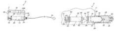
- FIG. 7is a side elevation view in partial section illustrating insertion of the syringe assembly into the infusion pump casing
- FIG. 8is a cross-sectional view illustrating the syringe assembly of FIG. 7 loaded in an operational position within the infusion pump;
- FIG. 9is a cross-sectional view along the line 9 - 9 in FIG. 8 ;
- FIG. 10is a cross-sectional view illustrating an alternative syringe assembly loaded in an operational position within the infusion pump.
- piston-type infusion pump 5in accordance with an exemplary embodiment of the present invention is shown for delivering medication 24 or other fluid (in phantom) to a patient along infusion path 14 .
- Infusion pump 5desirably includes sealed pump casing 7 , processing circuitry 200 , power cells 70 , motor 10 , gear train 28 , lead screw 15 , and drive piston 22 .
- Syringe assembly 12is positional within pump casing 7 such that drive piston 22 engages plunger 20 of syringe assembly 12 .
- processing circuitry 200controls the operation of infusion pump 5 .
- Motor 10is incrementally engaged to infuse medication to a patient at predetermined intervals. Upon engagement, motor 10 causes lead screw 15 to rotate by means of gear train 28 .
- drive piston 22is driven axially toward syringe assembly 12 , thereby pushing plunger 20 . This causes delivery of medication 24 from within syringe housing 26 of syringe assembly 12 .
- Infusion path 14is connected by connector 27 to dispensing tip 25 (see FIG. 5 ) of syringe housing 26 to provide fluidic communication between infusion pump 5 and a patient.
- Pump casing 7is desirably formed of a thermoplastic material and preferably made watertight by sealing any openings therein.
- pump casing 7supports LCD display 30 , keypad 42 , priming button 44 , battery door 40 , hinge 38 , pump door latch 48 , and pump door 36 .
- To load a syringe assembly 12 within casing 7pump door 36 is opened to expose the interior infusion port 50 and battery door 40 .
- Syringe assembly 12is configured to be moved axially through interior infusion port 50 into the interior of pump casing 7 such that plunger 20 axially engages drive piston 22 , as will be described in more detail hereinafter.
- pump door latch 48has been rotated away from pump casing 7 in order to release pump door 36 so it may pivot open at hinge 38 .
- Battery door 40is removable for replacing the power cells 70 .
- Infusion pump 5may have various configurations including various controls, power sources, drive means, access ports and doors, sizes and shapes.
- syringe assembly 12includes plunger 20 and syringe housing 26 .
- Seal rings 29 or the likeare provided between plunger 20 and syringe housing 26 to seal medication 24 within syringe housing 26 .
- Seal rings 29also provide a friction force between plunger 20 and syringe housing 26 . This friction force axially secures plunger 20 relative to syringe housing 26 such that an axial force on plunger 20 that is greater than the friction force is required to move plunger 20 relative to syringe housing 26 .
- drive piston 22is configured to selectively move plunger 20 axially inward relative to syringe housing 26 , which is axially fixed in place by door 36 of casing 7 , such that medication 24 is dispensed through dispensing tip 25 .
- Connection interface 23is provided adjacent dispensing tip 25 to facilitate connection to connector 27 .
- Various connection interfaces 23may be provided.
- plunger 20includes tubular body 31 which has a generally hollow interior 37 extending between closed end 33 and generally open end 35 .
- Generally open end 35is configured to receive drive piston 22 as will be described hereinafter.
- Plunger body 31may include vent holes 32 or the like to allow pressure to escape as drive piston 22 is advanced into hollow interior 37 .
- Interior annular groove 39is provided along the interior surface of plunger body 31 and is configured to receive a radially elastic member as described hereinafter to axially secure plunger 20 relative to drive piston 22 .
- Interior annular groove 39is desirably provided adjacent generally open end 35 , but may otherwise be positioned.
- Syringe assembly 12 as illustrated in FIGS. 4 and 5is pre-filled with medication 24 or the like and is ready for use in infusion pump 5 .
- drive piston 22includes tubular body 41 having a hollow interior portion 47 which is configured to receive lead screw 15 . Threads 44 adjacent open end 45 of piston body 41 are configured to engage threads 16 of lead screw 15 to facilitate driving motion of drive piston 22 .
- Drive piston 22is supported within casing 7 , either by lead screw 15 alone or via other support structures (not shown). Shoulder 51 may be provided about open end 45 to further support drive piston 22 within casing 7 .
- End 43 of piston body 41is configured to receive cap 49 which is desirably manufactured from an elastomeric material. Alternatively, end 43 may be manufactured as a closed end or cap 49 may be formed integrally therewith, for example, via overmolding.
- Exterior annular groove 53is provided about piston body 41 and is configured to receive and retain radially elastic member 60 .
- exterior annular groove 53desirably has flattened sides 55 extending generally parallel to one another. Exterior annular groove 53 is desirably positioned toward open end 45 , but may be otherwise positioned. Referring to FIG. 8 , interior annular groove 39 and exterior annular groove 53 are desirably axially aligned when syringe assembly 12 is fully installed in infusion pump 5 and cap 49 contacts plunger closed end 33 .
- syringe assembly 12is moved axially through interior infusion port 50 , as indicated by arrow A.
- End 43 of drive piston 22enters plunger 20 through open end 35 and passes through hollow interior 37 until cap 49 engages closed end 33 .
- radially elastic member 60enters through plunger open end 35 , radially elastic member 60 compresses such that radially elastic member 60 enters into the hollow interior 37 .
- inward taper 34is desirably provided about open end 35 .
- Radially elastic member 60As radially elastic member 60 axially aligns with interior annular groove 39 , radially elastic member 60 radially expands and engages interior annular groove 39 , thereby axially securing plunger 20 relative to drive piston 22 .
- Radially elastic member 60 , inward taper 34 and interior annular groove 39are desirably configured such that the insertion force required to insert and operatively engage plunger 20 with drive piston 22 is less than the friction force between plunger 20 and syringe housing 26 such that plunger 20 does not move relative to syringe housing 26 during insertion.
- radially elastic member 60With radially elastic member 60 engaged between plunger 20 and drive piston 22 , which is controllably axially fixed within casing 7 , radially elastic member 60 provides an additional force against axial movement of plunger 20 relative to syringe housing 26 . As such, a total force, equal to the friction force plus the elastic member additional force, axially secures plunger 20 relative to syringe housing 26 . However, since the elastic member additional force is provided between drive piston 22 and plunger 20 , this additional force does not have to be overcome to drive plunger 20 axially inwardly to dispense medication. As such, a more secure positioning between plunger 20 and syringe housing 26 is achieved without requiring a greater drive force.
- a reduced friction forcemay be utilized while still maintaining a desired total force.
- a prior art system including a seal ring configured to provide a friction force of 2 lbs. between plunger 20 and syringe housing 26would have a total force of 2 lbs.
- elastic member 60 , drive piston 22 and plunger 20are configured such that elastic member 60 provides an additional force of 0.5 lbs.
- the friction force provided by seal rings 29 between plunger 20 and syringe housing 26only needs to be 1.5 lbs.
- the total force securing plunger 20 relative to syringe housing 26remains the same, but the required drive force, i.e., the axial force required to overcome the friction force, is reduced from 2 lbs. to 1.5 lbs.
- the pump systemmay be operated more efficiently due to the reduction in the required drive force.
- annular groove 39When syringe assembly 12 is to be removed, an axial force opposite arrow A is applied to syringe assembly 12 .
- Radially elastic member 60again compresses and disengages from interior annular groove 39 .
- at least rear edge of annular groove 39has a tapered side wall 57 .
- Both side walls 57may be tapered.
- opposed side walls 57are angled relative to one another between approximately 90° and 175°, desirably at approximately 135° relative to one another.
- exterior annular groove 53is desirably deeper than interior annular groove 39 .
- interior annular groove 39 and radially elastic member 60are configured such that the force required to disengage radially elastic member 60 from interior annular groove 39 is less than the friction force such that the syringe assembly 12 is removed without separating syringe housing 26 from plunger 20 .
- radially elastic member 60is a canted coil spring 62 , as shown in FIG. 9 .
- An illustrative canted coil springis described in U.S. Pat. No. 4,655,462, which is incorporated herein in its entirety.
- Canted coil spring 62includes a plurality of coil means, with each of the coil means being interconnected with one another in a spaced-apart relationship and disposed at a preselected acute angle with a centerline of coiled spring 62 .
- canted coiled spring 62exerts a constant force in a loading direction approximately normal to the centerline in response to deflection of the coiled spring along the loading direction.
- canted coil spring 62is shown and described herein, other radially elastic members 60 , for example, a solid ring made from elastomeric material, may be utilized.
- plunger 20 ′ of syringe assembly 12 ′includes an exterior annular groove 39 ′ while drive piston 22 ′ includes an interior annular groove 53 ′.
- Rear end 35 ′ of plunger body 31 ′is configured to be received within drive piston 22 ′ and forward end 33 ′ forms a head.
- Seal rings 29 or the likeare provided between the head and syringe housing 26 .
- Radially elastic member 60is retained in interior annular groove 53 ′ and is engagable with exterior annular groove 39 ′ to axially secure plunger 20 ′ relative to drive piston 22 ′.
- the infusion pump assemblygenerally operates as in the previous embodiments.
Landscapes
- Health & Medical Sciences (AREA)
- Vascular Medicine (AREA)
- Engineering & Computer Science (AREA)
- Anesthesiology (AREA)
- Biomedical Technology (AREA)
- Heart & Thoracic Surgery (AREA)
- Hematology (AREA)
- Life Sciences & Earth Sciences (AREA)
- Animal Behavior & Ethology (AREA)
- General Health & Medical Sciences (AREA)
- Public Health (AREA)
- Veterinary Medicine (AREA)
- Infusion, Injection, And Reservoir Apparatuses (AREA)
Abstract
Description
Claims (7)
Priority Applications (13)
| Application Number | Priority Date | Filing Date | Title |
|---|---|---|---|
| US11/651,876US7803134B2 (en) | 2007-01-10 | 2007-01-10 | Syringe assembly and infusion pump assembly incorporating such |
| IL188620AIL188620A (en) | 2007-01-10 | 2008-01-07 | Infusion pump assembly |
| AU2008200081AAU2008200081B2 (en) | 2007-01-10 | 2008-01-08 | Syringe assembly and an infusion pump assembly incorporating such |
| CA2617401ACA2617401C (en) | 2007-01-10 | 2008-01-09 | Syringe assembly and an infusion pump assembly incorporating such |
| PL08250103TPL1944048T3 (en) | 2007-01-10 | 2008-01-09 | Syringe assembly and an infusion pump assembly incorporating such |
| JP2008002162AJP5558668B2 (en) | 2007-01-10 | 2008-01-09 | Syringe assembly and infusion pump assembly incorporating the same |
| SG200800205-7ASG144828A1 (en) | 2007-01-10 | 2008-01-09 | Syringe assembly and an infusion pump assembly incorporating such |
| ES08250103TES2379556T3 (en) | 2007-01-10 | 2008-01-09 | Syringe set and infusion pump assembly that incorporates it |
| KR1020080002431AKR101443579B1 (en) | 2007-01-10 | 2008-01-09 | A syringe assembly and an injection pump assembly incorporating the syringe assembly |
| EP08250103AEP1944048B1 (en) | 2007-01-10 | 2008-01-09 | Syringe assembly and an infusion pump assembly incorporating such |
| AT08250103TATE546178T1 (en) | 2007-01-10 | 2008-01-09 | SYRINGE ASSEMBLY AND INFUSION PUMP ASSEMBLY CONTAINING SAME |
| CN2008100095542ACN101239205B (en) | 2007-01-10 | 2008-01-10 | Syringe assembly and an infusion pump assembly incorporating such |
| HK08109747.9AHK1118237B (en) | 2007-01-10 | 2008-09-02 | Syringe assembly and an infusion pump assembly incorporating such |
Applications Claiming Priority (1)
| Application Number | Priority Date | Filing Date | Title |
|---|---|---|---|
| US11/651,876US7803134B2 (en) | 2007-01-10 | 2007-01-10 | Syringe assembly and infusion pump assembly incorporating such |
Publications (2)
| Publication Number | Publication Date |
|---|---|
| US20080167618A1 US20080167618A1 (en) | 2008-07-10 |
| US7803134B2true US7803134B2 (en) | 2010-09-28 |
Family
ID=39183178
Family Applications (1)
| Application Number | Title | Priority Date | Filing Date |
|---|---|---|---|
| US11/651,876Expired - Fee RelatedUS7803134B2 (en) | 2007-01-10 | 2007-01-10 | Syringe assembly and infusion pump assembly incorporating such |
Country Status (12)
| Country | Link |
|---|---|
| US (1) | US7803134B2 (en) |
| EP (1) | EP1944048B1 (en) |
| JP (1) | JP5558668B2 (en) |
| KR (1) | KR101443579B1 (en) |
| CN (1) | CN101239205B (en) |
| AT (1) | ATE546178T1 (en) |
| AU (1) | AU2008200081B2 (en) |
| CA (1) | CA2617401C (en) |
| ES (1) | ES2379556T3 (en) |
| IL (1) | IL188620A (en) |
| PL (1) | PL1944048T3 (en) |
| SG (1) | SG144828A1 (en) |
Cited By (34)
| Publication number | Priority date | Publication date | Assignee | Title |
|---|---|---|---|---|
| US8105269B2 (en) | 2008-10-24 | 2012-01-31 | Baxter International Inc. | In situ tubing measurements for infusion pumps |
| US8137083B2 (en) | 2009-03-11 | 2012-03-20 | Baxter International Inc. | Infusion pump actuators, system and method for controlling medical fluid flowrate |
| US8382447B2 (en) | 2009-12-31 | 2013-02-26 | Baxter International, Inc. | Shuttle pump with controlled geometry |
| US8567235B2 (en) | 2010-06-29 | 2013-10-29 | Baxter International Inc. | Tube measurement technique using linear actuator and pressure sensor |
| US20130338576A1 (en)* | 2012-06-15 | 2013-12-19 | Wayne C. Jaeschke, Jr. | Portable infusion pump with pressure and temperature compensation |
| US8939935B2 (en) | 2011-09-02 | 2015-01-27 | Unitract Syringe Pty Ltd | Drive mechanism for drug delivery pumps with integrated status indication |
| USD723157S1 (en) | 2013-03-12 | 2015-02-24 | Unitract Syringe Pty Ltd | Drug delivery pump |
| USD745142S1 (en) | 2012-08-30 | 2015-12-08 | Unitract Syringe Pty Ltd | Drug delivery pump |
| US9480797B1 (en) | 2015-10-28 | 2016-11-01 | Bayer Healthcare Llc | System and method for syringe plunger engagement with an injector |
| US9511189B2 (en) | 2011-09-02 | 2016-12-06 | Unitract Syringe Pty Ltd | Insertion mechanism for a drug delivery pump |
| US9694131B2 (en) | 2003-11-25 | 2017-07-04 | Bayer Healthcare Llc | Medical injector system |
| US9707337B2 (en) | 2011-09-13 | 2017-07-18 | Unitract Syringe Pty Ltd | Sterile fluid pathway connection to drug containers for drug delivery pumps |
| US9707335B2 (en) | 2011-09-02 | 2017-07-18 | Unitract Syringe Pty Ltd | Drive mechanism for drug delivery pumps with integrated status indication |
| USD794770S1 (en) | 2015-06-26 | 2017-08-15 | Unitract Syringe Pty Ltd | Drug delivery pump |
| USD794771S1 (en) | 2015-07-10 | 2017-08-15 | Unitract Syringe Pty Ltd. | Drug delivery pump |
| US9737655B2 (en) | 2013-08-23 | 2017-08-22 | Unitract Syringe Pty Ltd | Integrated pierceable seal fluid pathway connection and drug containers for drug delivery pumps |
| US9744305B2 (en) | 2012-09-28 | 2017-08-29 | Bayer Healthcare Llc | Quick release plunger |
| US9802030B2 (en) | 2013-01-25 | 2017-10-31 | Unl Holdings Llc | Integrated sliding seal fluid pathway connection and drug containers for drug delivery pumps |
| US9814832B2 (en) | 2011-09-02 | 2017-11-14 | Unl Holdings Llc | Drive mechanism for drug delivery pumps with integrated status indication |
| US9855390B2 (en) | 2006-03-15 | 2018-01-02 | Bayer Healthcare Llc | Plunger covers and plungers for use in syringes |
| US9987419B2 (en) | 2012-08-29 | 2018-06-05 | Unl Holdings Llc | Controlled delivery drive mechanisms for drug delivery pumps |
| USD847985S1 (en) | 2007-03-14 | 2019-05-07 | Bayer Healthcare Llc | Syringe plunger cover |
| US10695487B2 (en) | 2016-08-30 | 2020-06-30 | Unl Holdings Llc | Controlled delivery drive mechanisms for drug delivery pumps |
| US10806855B2 (en) | 2014-09-29 | 2020-10-20 | Unl Holdings Llc | Rigid needle insertion mechanism for a drug delivery pump |
| US10806852B2 (en) | 2014-03-19 | 2020-10-20 | Bayer Healthcare Llc | System for syringe engagement to an injector |
| US11033676B2 (en) | 2016-08-08 | 2021-06-15 | Unl Holdings Llc | Drug delivery device and method for connecting a fluid flowpath |
| US11033679B2 (en) | 2012-03-12 | 2021-06-15 | Unl Holdings Llc | Fill-finish cartridges for sterile fluid pathway assemblies and drug delivery devices incorporating fill-finish cartridges |
| USD923177S1 (en) | 2014-11-07 | 2021-06-22 | Unl Holdings Llc | Drug delivery pump |
| US11173244B2 (en) | 2011-09-02 | 2021-11-16 | Unl Holdings Llc | Drive mechanism for drug delivery pumps with integrated status indication |
| USD942005S1 (en) | 2007-03-14 | 2022-01-25 | Bayer Healthcare Llc | Orange syringe plunger cover |
| US11883636B2 (en) | 2018-02-27 | 2024-01-30 | Bayer Healthcare Llc | Syringe plunger engagement mechanism |
| US11969582B2 (en) | 2017-01-06 | 2024-04-30 | Bayer Healthcare Llc | Syringe plunger with dynamic seal |
| US11998718B2 (en) | 2020-06-18 | 2024-06-04 | Bayer Healthcare Llc | System and method for syringe plunger engagement with an injector |
| USD1031029S1 (en) | 2003-11-25 | 2024-06-11 | Bayer Healthcare Llc | Syringe plunger |
Families Citing this family (19)
| Publication number | Priority date | Publication date | Assignee | Title |
|---|---|---|---|---|
| JP5546755B2 (en)* | 2008-09-11 | 2014-07-09 | 株式会社根本杏林堂 | Contrast system |
| US8157769B2 (en) | 2009-09-15 | 2012-04-17 | Medimop Medical Projects Ltd. | Cartridge insertion assembly for drug delivery system |
| US10071198B2 (en) | 2012-11-02 | 2018-09-11 | West Pharma. Servicees IL, Ltd. | Adhesive structure for medical device |
| USD810279S1 (en) | 2009-09-15 | 2018-02-13 | Medimop Medical Projects Ltd. | Injector device |
| GB2481066A (en)* | 2010-06-11 | 2011-12-14 | Britannia Pharmaceuticals Ltd | Portable case for infusion |
| US9421323B2 (en) | 2013-01-03 | 2016-08-23 | Medimop Medical Projects Ltd. | Door and doorstop for portable one use drug delivery apparatus |
| CN103431921B (en)* | 2013-08-28 | 2015-09-02 | 史其新 | For the operating theater instruments of meiofauna channel portal vein intrahepatic islet transplantation |
| CN113181477B (en) | 2015-06-04 | 2023-07-14 | 麦迪麦珀医疗工程有限公司 | Cartridge insertion for drug delivery device |
| US11135358B2 (en)* | 2015-09-18 | 2021-10-05 | Sanofi-Aventis Deutschland Gmbh | Drug delivery device |
| CN109310831B (en) | 2016-06-02 | 2021-11-23 | 西医药服务以色列有限公司 | Three position needle retraction |
| US10549044B2 (en)* | 2016-06-09 | 2020-02-04 | Becton, Dickinson And Company | Spacer assembly for drug delivery system |
| JP7059251B2 (en) | 2016-08-01 | 2022-04-25 | ウェスト ファーマ サービシーズ イスラエル リミテッド | A spring that prevents the door from closing halfway |
| EP3630226A1 (en) | 2017-05-30 | 2020-04-08 | West Pharma. Services Il, Ltd. | Modular drive train for wearable injector |
| JP7111809B2 (en) | 2017-10-16 | 2022-08-02 | ベクトン・ディキンソン・アンド・カンパニー | Spacer assembly for drug delivery device |
| JP7402799B2 (en) | 2017-12-22 | 2023-12-21 | ウェスト ファーマ サービシーズ イスラエル リミテッド | Syringes available with different cartridge sizes |
| JP2023523266A (en)* | 2020-04-21 | 2023-06-02 | メドテック コンセプト エルエルシー | Syringe, method and assembly for manufacturing such syringe |
| CN113350675A (en)* | 2021-06-02 | 2021-09-07 | 杨迪迪 | Anorectal administration device |
| KR102579340B1 (en) | 2021-08-24 | 2023-09-19 | 충북대학교 산학협력단 | Continuous and safe automatic drug infusion device and method for patients |
| KR102730130B1 (en) | 2022-05-09 | 2024-11-14 | 충북대학교 산학협력단 | Method for applying a statistical formula model in determining the optimal sedation quantity and an apparatus for performing the method |
Citations (40)
| Publication number | Priority date | Publication date | Assignee | Title |
|---|---|---|---|---|
| US2629376A (en) | 1948-07-22 | 1953-02-24 | Sedat | Injection syringe |
| US2756748A (en) | 1952-01-05 | 1956-07-31 | Becton Dickinson Co | Syringe |
| US2895773A (en) | 1956-10-22 | 1959-07-21 | Robert K Mcconnaughey | Variable diameter tensed ring piston |
| US3151617A (en)* | 1962-05-29 | 1964-10-06 | Baum Leo | Syringe |
| US3540760A (en) | 1969-03-24 | 1970-11-17 | Weatherhead Co | Quick connect coupling |
| US3987940A (en) | 1971-11-11 | 1976-10-26 | Mpl, Inc. | Glass tube and thermoplastic resin finger-grip and nose sleeve syringe body assembly |
| US4030498A (en) | 1974-10-25 | 1977-06-21 | Baxter Travenol Laboratories, Inc. | Syringe |
| US4030496A (en) | 1975-07-28 | 1977-06-21 | Contraves Ag | Syringe for injecting liquids into blood vessels of living bodies |
| US4655462A (en) | 1985-01-07 | 1987-04-07 | Peter J. Balsells | Canted coiled spring and seal |
| US4773900A (en) | 1986-08-20 | 1988-09-27 | Cochran Ulrich D | Infusion device |
| US5062830A (en) | 1990-04-04 | 1991-11-05 | Derata Corporation | Dry disposable nozzle assembly for medical jet injector |
| US5085638A (en)* | 1988-03-31 | 1992-02-04 | David Farbstein | Single use disposable syringe |
| US5741232A (en) | 1992-08-17 | 1998-04-21 | Medrad, Inc. | Front loading medical injector and syringe for use therewith |
| US5782815A (en) | 1995-01-26 | 1998-07-21 | Yuji Yanai | Glass cartridge for injection syringe prefilled with pharmaceutical liquid |
| US5873861A (en) | 1996-11-12 | 1999-02-23 | Medrad, Inc. | Plunger systems |
| US5944694A (en) | 1996-11-12 | 1999-08-31 | Medrad, Inc. | Prefillable syringes and injectors for use therewith |
| US5947935A (en) | 1996-11-12 | 1999-09-07 | Medrad, Inc. | Syringes, syringe plungers and injector systems |
| US5947929A (en) | 1997-08-22 | 1999-09-07 | Coeur Laboratories, Inc. | Front-load angiographic injector system, angiographic syringe and plunger for angiographic syringe |
| US5993423A (en) | 1998-08-18 | 1999-11-30 | Choi; Soo Bong | Portable automatic syringe device and injection needle unit thereof |
| DE20011366U1 (en) | 2000-06-28 | 2000-09-14 | Lin, Te-Fa, Taichung | Syringe device |
| US6248093B1 (en) | 1998-10-29 | 2001-06-19 | Minimed Inc. | Compact pump drive system |
| US6287521B1 (en)* | 1996-08-27 | 2001-09-11 | Atossa Healthcare, Inc. | Methods and devices for obtaining and assaying mammary fluid samples for evaluating breast diseases, including cancer |
| US20010034502A1 (en)* | 2000-03-29 | 2001-10-25 | Moberg Sheldon B. | Methods, apparatuses, and uses for infusion pump fluid pressure and force detection |
| WO2002004049A1 (en) | 2000-07-10 | 2002-01-17 | Medrad, Inc. | Improvements relating to medical injector systems |
| US6413238B1 (en) | 1999-09-17 | 2002-07-02 | Baxter International Inc | Fluid dispenser with stabilized fluid flow |
| US6425885B1 (en) | 1999-12-20 | 2002-07-30 | Ultradent Products, Inc. | Hydraulic syringe |
| US20030163089A1 (en) | 2002-02-28 | 2003-08-28 | Bynum Gail Beth | Child safety cap for syringe pump |
| US20030163090A1 (en) | 2002-02-28 | 2003-08-28 | Blomquist Michael L. | Syringe pump control systems and methods |
| US6652489B2 (en) | 2000-02-07 | 2003-11-25 | Medrad, Inc. | Front-loading medical injector and syringes, syringe interfaces, syringe adapters and syringe plungers for use therewith |
| US6656148B2 (en) | 1999-06-18 | 2003-12-02 | Animas Corporation | Infusion pump with a sealed drive mechanism and improved method of occlusion detection |
| US6733475B2 (en)* | 2002-02-08 | 2004-05-11 | Taiject Medical Device Co., Ltd. | Safety syringe of easy to pull out the plunger |
| US6800071B1 (en) | 1998-10-29 | 2004-10-05 | Medtronic Minimed, Inc. | Fluid reservoir piston |
| WO2004103429A2 (en) | 2003-05-26 | 2004-12-02 | Woo In Baik | Disposable syringe |
| US6854620B2 (en) | 2001-04-13 | 2005-02-15 | Nipro Diabetes, Systems, Inc. | Drive system for an infusion pump |
| EP1570875A1 (en) | 2004-03-04 | 2005-09-07 | Roche Diagnostics GmbH | Pyrotechnically driven needle-free liquid jet injection device with low-cost components and production |
| US7000806B2 (en) | 2000-10-23 | 2006-02-21 | Medical Instill Technologies, Inc. | Fluid dispenser having a housing and flexible inner bladder |
| US7008403B1 (en) | 2002-07-19 | 2006-03-07 | Cognitive Ventures Corporation | Infusion pump and method for use |
| US7029458B2 (en) | 1996-03-29 | 2006-04-18 | Medrad, Inc. | Front-loading syringe adapter for front-loading medical injector |
| US7033338B2 (en) | 2002-02-28 | 2006-04-25 | Smiths Medical Md, Inc. | Cartridge and rod for axially loading medication pump |
| US7041081B2 (en) | 2000-05-26 | 2006-05-09 | Orchis Company Limited | Continuous liquid infusion device |
Family Cites Families (12)
| Publication number | Priority date | Publication date | Assignee | Title |
|---|---|---|---|---|
| BE546392A (en)* | 1956-01-23 | |||
| US3998223A (en)* | 1975-10-24 | 1976-12-21 | The United States Of America As Represented By The Secretary Of The Navy | Syringe apparatus |
| US4257426A (en)* | 1979-06-22 | 1981-03-24 | Marquest Medical Products, Inc. | Vacuum assisted anti-coagulant syringe device for taking blood samples |
| US5370628A (en)* | 1991-07-31 | 1994-12-06 | Allison; Alan C. | Safety needle and syringe |
| US5935201A (en)* | 1995-12-22 | 1999-08-10 | Stmicroelectronics, S.R.L. | Multiplier circuit for multiplication operation between binary and twos complement numbers |
| JP2002000725A (en)* | 2000-06-20 | 2002-01-08 | Eisuke Fujimoto | Disposable needleless injector |
| US6835191B2 (en)* | 2001-12-21 | 2004-12-28 | 3M Innovative Properties Co. | Self-venting movable seal and plunger |
| WO2003068290A2 (en)* | 2002-02-11 | 2003-08-21 | Antares Pharma, Inc. | Intradermal injector |
| JP2004201969A (en)* | 2002-12-25 | 2004-07-22 | Showa Yakuhin Kako Kk | Device of attaching cartridge holder for cartridge-type electric injection apparatus for dental use |
| US7666169B2 (en)* | 2003-11-25 | 2010-02-23 | Medrad, Inc. | Syringe and syringe plungers for use with medical injectors |
| US20060100581A1 (en)* | 2004-08-13 | 2006-05-11 | Mogensen Lasse W | Reservoir for front end loaded infusion device |
| US9522237B2 (en)* | 2005-01-07 | 2016-12-20 | Becton, Dickinson And Company | Positive displacement flush syringe |
- 2007
- 2007-01-10USUS11/651,876patent/US7803134B2/ennot_activeExpired - Fee Related
- 2008
- 2008-01-07ILIL188620Apatent/IL188620A/enactiveIP Right Grant
- 2008-01-08AUAU2008200081Apatent/AU2008200081B2/ennot_activeCeased
- 2008-01-09CACA2617401Apatent/CA2617401C/ennot_activeExpired - Fee Related
- 2008-01-09ATAT08250103Tpatent/ATE546178T1/enactive
- 2008-01-09PLPL08250103Tpatent/PL1944048T3/enunknown
- 2008-01-09JPJP2008002162Apatent/JP5558668B2/ennot_activeExpired - Fee Related
- 2008-01-09KRKR1020080002431Apatent/KR101443579B1/ennot_activeExpired - Fee Related
- 2008-01-09SGSG200800205-7Apatent/SG144828A1/enunknown
- 2008-01-09ESES08250103Tpatent/ES2379556T3/enactiveActive
- 2008-01-09EPEP08250103Apatent/EP1944048B1/enactiveActive
- 2008-01-10CNCN2008100095542Apatent/CN101239205B/ennot_activeExpired - Fee Related
Patent Citations (46)
| Publication number | Priority date | Publication date | Assignee | Title |
|---|---|---|---|---|
| US2629376A (en) | 1948-07-22 | 1953-02-24 | Sedat | Injection syringe |
| US2756748A (en) | 1952-01-05 | 1956-07-31 | Becton Dickinson Co | Syringe |
| US2895773A (en) | 1956-10-22 | 1959-07-21 | Robert K Mcconnaughey | Variable diameter tensed ring piston |
| US3151617A (en)* | 1962-05-29 | 1964-10-06 | Baum Leo | Syringe |
| US3540760A (en) | 1969-03-24 | 1970-11-17 | Weatherhead Co | Quick connect coupling |
| US3987940A (en) | 1971-11-11 | 1976-10-26 | Mpl, Inc. | Glass tube and thermoplastic resin finger-grip and nose sleeve syringe body assembly |
| US4030498A (en) | 1974-10-25 | 1977-06-21 | Baxter Travenol Laboratories, Inc. | Syringe |
| US4030496A (en) | 1975-07-28 | 1977-06-21 | Contraves Ag | Syringe for injecting liquids into blood vessels of living bodies |
| US4655462A (en) | 1985-01-07 | 1987-04-07 | Peter J. Balsells | Canted coiled spring and seal |
| US4773900A (en) | 1986-08-20 | 1988-09-27 | Cochran Ulrich D | Infusion device |
| US5085638A (en)* | 1988-03-31 | 1992-02-04 | David Farbstein | Single use disposable syringe |
| US5062830A (en) | 1990-04-04 | 1991-11-05 | Derata Corporation | Dry disposable nozzle assembly for medical jet injector |
| US5741232A (en) | 1992-08-17 | 1998-04-21 | Medrad, Inc. | Front loading medical injector and syringe for use therewith |
| US6090064A (en) | 1992-08-17 | 2000-07-18 | Medrad, Inc. | Front loading medical injector and syringe for use therewith |
| US5782815A (en) | 1995-01-26 | 1998-07-21 | Yuji Yanai | Glass cartridge for injection syringe prefilled with pharmaceutical liquid |
| US7029458B2 (en) | 1996-03-29 | 2006-04-18 | Medrad, Inc. | Front-loading syringe adapter for front-loading medical injector |
| US6287521B1 (en)* | 1996-08-27 | 2001-09-11 | Atossa Healthcare, Inc. | Methods and devices for obtaining and assaying mammary fluid samples for evaluating breast diseases, including cancer |
| US5873861A (en) | 1996-11-12 | 1999-02-23 | Medrad, Inc. | Plunger systems |
| US5947935A (en) | 1996-11-12 | 1999-09-07 | Medrad, Inc. | Syringes, syringe plungers and injector systems |
| US5944694A (en) | 1996-11-12 | 1999-08-31 | Medrad, Inc. | Prefillable syringes and injectors for use therewith |
| US5947929A (en) | 1997-08-22 | 1999-09-07 | Coeur Laboratories, Inc. | Front-load angiographic injector system, angiographic syringe and plunger for angiographic syringe |
| US5993423A (en) | 1998-08-18 | 1999-11-30 | Choi; Soo Bong | Portable automatic syringe device and injection needle unit thereof |
| US6248093B1 (en) | 1998-10-29 | 2001-06-19 | Minimed Inc. | Compact pump drive system |
| US6800071B1 (en) | 1998-10-29 | 2004-10-05 | Medtronic Minimed, Inc. | Fluid reservoir piston |
| US6656148B2 (en) | 1999-06-18 | 2003-12-02 | Animas Corporation | Infusion pump with a sealed drive mechanism and improved method of occlusion detection |
| US6413238B1 (en) | 1999-09-17 | 2002-07-02 | Baxter International Inc | Fluid dispenser with stabilized fluid flow |
| US6425885B1 (en) | 1999-12-20 | 2002-07-30 | Ultradent Products, Inc. | Hydraulic syringe |
| US6652489B2 (en) | 2000-02-07 | 2003-11-25 | Medrad, Inc. | Front-loading medical injector and syringes, syringe interfaces, syringe adapters and syringe plungers for use therewith |
| US20010034502A1 (en)* | 2000-03-29 | 2001-10-25 | Moberg Sheldon B. | Methods, apparatuses, and uses for infusion pump fluid pressure and force detection |
| US6659980B2 (en) | 2000-03-29 | 2003-12-09 | Medtronic Minimed Inc | Methods, apparatuses, and uses for infusion pump fluid pressure and force detection |
| US7041081B2 (en) | 2000-05-26 | 2006-05-09 | Orchis Company Limited | Continuous liquid infusion device |
| DE20011366U1 (en) | 2000-06-28 | 2000-09-14 | Lin, Te-Fa, Taichung | Syringe device |
| WO2002004049A1 (en) | 2000-07-10 | 2002-01-17 | Medrad, Inc. | Improvements relating to medical injector systems |
| US20040158205A1 (en)* | 2000-07-10 | 2004-08-12 | Savage Rodney Brian | Medical injector systems |
| US7000806B2 (en) | 2000-10-23 | 2006-02-21 | Medical Instill Technologies, Inc. | Fluid dispenser having a housing and flexible inner bladder |
| US6854620B2 (en) | 2001-04-13 | 2005-02-15 | Nipro Diabetes, Systems, Inc. | Drive system for an infusion pump |
| US7025226B2 (en) | 2001-04-13 | 2006-04-11 | Nipro Diabetes Systems, Inc. | Drive system for an infusion pump |
| US6733475B2 (en)* | 2002-02-08 | 2004-05-11 | Taiject Medical Device Co., Ltd. | Safety syringe of easy to pull out the plunger |
| US20030163090A1 (en) | 2002-02-28 | 2003-08-28 | Blomquist Michael L. | Syringe pump control systems and methods |
| US7033338B2 (en) | 2002-02-28 | 2006-04-25 | Smiths Medical Md, Inc. | Cartridge and rod for axially loading medication pump |
| US7041082B2 (en) | 2002-02-28 | 2006-05-09 | Smiths Medical Md, Inc. | Syringe pump control systems and methods |
| US20030163089A1 (en) | 2002-02-28 | 2003-08-28 | Bynum Gail Beth | Child safety cap for syringe pump |
| US7008403B1 (en) | 2002-07-19 | 2006-03-07 | Cognitive Ventures Corporation | Infusion pump and method for use |
| WO2004103429A2 (en) | 2003-05-26 | 2004-12-02 | Woo In Baik | Disposable syringe |
| EP1570875A1 (en) | 2004-03-04 | 2005-09-07 | Roche Diagnostics GmbH | Pyrotechnically driven needle-free liquid jet injection device with low-cost components and production |
| WO2005094923A1 (en) | 2004-03-04 | 2005-10-13 | Roche Diagnostics Gmbh | Pyrotechnically driven needle-free liquid jet injection device with low-cost components and production |
Cited By (62)
| Publication number | Priority date | Publication date | Assignee | Title |
|---|---|---|---|---|
| US10434249B2 (en) | 2003-11-25 | 2019-10-08 | Bayer Healthcare Llc | Medical injector system |
| US9694131B2 (en) | 2003-11-25 | 2017-07-04 | Bayer Healthcare Llc | Medical injector system |
| USD1031029S1 (en) | 2003-11-25 | 2024-06-11 | Bayer Healthcare Llc | Syringe plunger |
| US11596735B2 (en) | 2003-11-25 | 2023-03-07 | Bayer Healthcare Llc | Medical injector system |
| US10894124B2 (en) | 2003-11-25 | 2021-01-19 | Bayer Healthcare Llc | Medical injector system |
| US10668221B2 (en) | 2006-03-15 | 2020-06-02 | Bayer Healthcare Llc | Plunger covers and plungers for use in syringes |
| US9855390B2 (en) | 2006-03-15 | 2018-01-02 | Bayer Healthcare Llc | Plunger covers and plungers for use in syringes |
| USD847985S1 (en) | 2007-03-14 | 2019-05-07 | Bayer Healthcare Llc | Syringe plunger cover |
| USD942005S1 (en) | 2007-03-14 | 2022-01-25 | Bayer Healthcare Llc | Orange syringe plunger cover |
| US8105269B2 (en) | 2008-10-24 | 2012-01-31 | Baxter International Inc. | In situ tubing measurements for infusion pumps |
| US8496613B2 (en) | 2008-10-24 | 2013-07-30 | Baxter International Inc. | In situ tubing measurements for infusion pumps |
| US8137083B2 (en) | 2009-03-11 | 2012-03-20 | Baxter International Inc. | Infusion pump actuators, system and method for controlling medical fluid flowrate |
| US8382447B2 (en) | 2009-12-31 | 2013-02-26 | Baxter International, Inc. | Shuttle pump with controlled geometry |
| US8567235B2 (en) | 2010-06-29 | 2013-10-29 | Baxter International Inc. | Tube measurement technique using linear actuator and pressure sensor |
| US9511189B2 (en) | 2011-09-02 | 2016-12-06 | Unitract Syringe Pty Ltd | Insertion mechanism for a drug delivery pump |
| US9707335B2 (en) | 2011-09-02 | 2017-07-18 | Unitract Syringe Pty Ltd | Drive mechanism for drug delivery pumps with integrated status indication |
| US10806854B2 (en) | 2011-09-02 | 2020-10-20 | Unl Holdings Llc | Insertion mechanism for a drug delivery pump |
| US10549029B2 (en) | 2011-09-02 | 2020-02-04 | Unl Holdings Llc | Drive mechanism for drug delivery pumps with integrated status indication |
| US9999727B2 (en) | 2011-09-02 | 2018-06-19 | Unl Holdings Llc | Drive mechanism for drug delivery pumps with integrated status indication |
| US8939935B2 (en) | 2011-09-02 | 2015-01-27 | Unitract Syringe Pty Ltd | Drive mechanism for drug delivery pumps with integrated status indication |
| US10322231B2 (en) | 2011-09-02 | 2019-06-18 | UNL Holdings | Drive mechanism for drug delivery pumps with integrated status indication |
| US9814832B2 (en) | 2011-09-02 | 2017-11-14 | Unl Holdings Llc | Drive mechanism for drug delivery pumps with integrated status indication |
| US11173244B2 (en) | 2011-09-02 | 2021-11-16 | Unl Holdings Llc | Drive mechanism for drug delivery pumps with integrated status indication |
| US10918788B2 (en) | 2011-09-02 | 2021-02-16 | Unl Holdings Llc | Drive mechanism for drug delivery pumps with integrated status indication |
| US10369274B2 (en) | 2011-09-13 | 2019-08-06 | Unl Holdings Llc | Sterile fluid pathway connection to drug containers for drug delivery pumps |
| US9707337B2 (en) | 2011-09-13 | 2017-07-18 | Unitract Syringe Pty Ltd | Sterile fluid pathway connection to drug containers for drug delivery pumps |
| US11484644B2 (en) | 2011-09-13 | 2022-11-01 | Unl Holdings Llc | Sterile fluid pathway connection to drug containers for drug delivery pumps |
| US11033679B2 (en) | 2012-03-12 | 2021-06-15 | Unl Holdings Llc | Fill-finish cartridges for sterile fluid pathway assemblies and drug delivery devices incorporating fill-finish cartridges |
| US20130338576A1 (en)* | 2012-06-15 | 2013-12-19 | Wayne C. Jaeschke, Jr. | Portable infusion pump with pressure and temperature compensation |
| US10251996B2 (en) | 2012-08-29 | 2019-04-09 | Unl Holdings Llc | Variable rate controlled delivery drive mechanisms for drug delivery pumps |
| US9987419B2 (en) | 2012-08-29 | 2018-06-05 | Unl Holdings Llc | Controlled delivery drive mechanisms for drug delivery pumps |
| US10092693B2 (en) | 2012-08-29 | 2018-10-09 | Unl Holdings Llc | Controlled delivery drive mechanisms for drug delivery pumps |
| US11135356B2 (en) | 2012-08-29 | 2021-10-05 | Unl Holdings Llc | Controlled delivery drive mechanisms for drug delivery pumps |
| US10933189B2 (en) | 2012-08-29 | 2021-03-02 | Unl Holdings Llc | Variable rate controlled delivery drive mechanisms for drug delivery pumps |
| USD745142S1 (en) | 2012-08-30 | 2015-12-08 | Unitract Syringe Pty Ltd | Drug delivery pump |
| USD768288S1 (en) | 2012-08-30 | 2016-10-04 | Unitract Syringe Pty Ltd | Drug delivery pump |
| US10286152B2 (en) | 2012-09-28 | 2019-05-14 | Bayer Healthcare Llc | Quick release plunger |
| US9744305B2 (en) | 2012-09-28 | 2017-08-29 | Bayer Healthcare Llc | Quick release plunger |
| US10994114B2 (en) | 2013-01-25 | 2021-05-04 | Unl Holdings Llc | Integrated sliding seal fluid pathway connection and drug containers for drug delivery pumps |
| US9802030B2 (en) | 2013-01-25 | 2017-10-31 | Unl Holdings Llc | Integrated sliding seal fluid pathway connection and drug containers for drug delivery pumps |
| USD791306S1 (en) | 2013-01-25 | 2017-07-04 | Unitract Syringe Pty Ltd | Drug delivery pump |
| USD886986S1 (en) | 2013-03-12 | 2020-06-09 | Unl Holdings Llc | Drug delivery pump |
| USD723157S1 (en) | 2013-03-12 | 2015-02-24 | Unitract Syringe Pty Ltd | Drug delivery pump |
| US11040135B2 (en) | 2013-08-23 | 2021-06-22 | Unl Holdings Llc | Integrated pierceable seal fluid pathway connection and drug containers for drug delivery pumps |
| US9737655B2 (en) | 2013-08-23 | 2017-08-22 | Unitract Syringe Pty Ltd | Integrated pierceable seal fluid pathway connection and drug containers for drug delivery pumps |
| US11103637B2 (en) | 2014-03-19 | 2021-08-31 | Bayer Healthcare Llc | System for syringe engagement to an injector |
| US11383029B2 (en) | 2014-03-19 | 2022-07-12 | Bayer Healthcare Llc | System for syringe engagement to an injector |
| US10806852B2 (en) | 2014-03-19 | 2020-10-20 | Bayer Healthcare Llc | System for syringe engagement to an injector |
| US10806855B2 (en) | 2014-09-29 | 2020-10-20 | Unl Holdings Llc | Rigid needle insertion mechanism for a drug delivery pump |
| USD923177S1 (en) | 2014-11-07 | 2021-06-22 | Unl Holdings Llc | Drug delivery pump |
| USD794770S1 (en) | 2015-06-26 | 2017-08-15 | Unitract Syringe Pty Ltd | Drug delivery pump |
| USD856506S1 (en) | 2015-07-10 | 2019-08-13 | Unl Holdings Llc | Drug delivery pump |
| USD794771S1 (en) | 2015-07-10 | 2017-08-15 | Unitract Syringe Pty Ltd. | Drug delivery pump |
| US9480797B1 (en) | 2015-10-28 | 2016-11-01 | Bayer Healthcare Llc | System and method for syringe plunger engagement with an injector |
| US10512721B2 (en) | 2015-10-28 | 2019-12-24 | Bayer Healthcare Llc | System and method for syringe plunger engagement with an injector |
| US11547794B2 (en) | 2015-10-28 | 2023-01-10 | Bayer Healthcare Llc | System and method for syringe plunger engagement with an injector |
| US12102793B2 (en) | 2015-10-28 | 2024-10-01 | Bayer Healthcare Llc | System and method for syringe plunger engagement with an injector |
| US11033676B2 (en) | 2016-08-08 | 2021-06-15 | Unl Holdings Llc | Drug delivery device and method for connecting a fluid flowpath |
| US10695487B2 (en) | 2016-08-30 | 2020-06-30 | Unl Holdings Llc | Controlled delivery drive mechanisms for drug delivery pumps |
| US11969582B2 (en) | 2017-01-06 | 2024-04-30 | Bayer Healthcare Llc | Syringe plunger with dynamic seal |
| US11883636B2 (en) | 2018-02-27 | 2024-01-30 | Bayer Healthcare Llc | Syringe plunger engagement mechanism |
| US11998718B2 (en) | 2020-06-18 | 2024-06-04 | Bayer Healthcare Llc | System and method for syringe plunger engagement with an injector |
Also Published As
| Publication number | Publication date |
|---|---|
| IL188620A0 (en) | 2008-11-03 |
| ATE546178T1 (en) | 2012-03-15 |
| JP2008173471A (en) | 2008-07-31 |
| IL188620A (en) | 2012-03-29 |
| CN101239205B (en) | 2013-04-03 |
| CA2617401A1 (en) | 2008-07-10 |
| SG144828A1 (en) | 2008-08-28 |
| US20080167618A1 (en) | 2008-07-10 |
| CA2617401C (en) | 2015-12-22 |
| EP1944048B1 (en) | 2012-02-22 |
| EP1944048A1 (en) | 2008-07-16 |
| JP5558668B2 (en) | 2014-07-23 |
| KR20080065924A (en) | 2008-07-15 |
| PL1944048T3 (en) | 2012-07-31 |
| ES2379556T3 (en) | 2012-04-27 |
| KR101443579B1 (en) | 2014-09-23 |
| HK1118237A1 (en) | 2009-02-06 |
| CN101239205A (en) | 2008-08-13 |
| AU2008200081A1 (en) | 2008-07-24 |
| AU2008200081B2 (en) | 2012-11-29 |
Similar Documents
| Publication | Publication Date | Title |
|---|---|---|
| US7803134B2 (en) | Syringe assembly and infusion pump assembly incorporating such | |
| US10632253B2 (en) | Liquid medicine administration apparatus and liquid medicine administration unit | |
| US11324883B2 (en) | Ambulatory infusion system initialization | |
| EP1930037B1 (en) | Syringe assembly and an infusion pump assembly incorporating such | |
| US10188789B2 (en) | Fluid infusion device with safety coupling | |
| KR20180018116A (en) | Drug cartridge and drug infusion device including the same | |
| US10279128B2 (en) | Systems for managing reservoir chamber pressure | |
| US20120165754A1 (en) | Syringe piston with fin-shaped circumferential sealing element | |
| HK1118237B (en) | Syringe assembly and an infusion pump assembly incorporating such | |
| HK1118490B (en) | Syringe assembly and an infusion pump assembly incorporating such | |
| US9833563B2 (en) | Systems for managing reservoir chamber pressure | |
| US20190151551A1 (en) | Delivery device with a connector having displaceable portions |
Legal Events
| Date | Code | Title | Description |
|---|---|---|---|
| AS | Assignment | Owner name:ANIMAS CORPORATION, PENNSYLVANIA Free format text:ASSIGNMENT OF ASSIGNORS INTEREST;ASSIGNORS:SHARIFI, BAHRAM;PAUL, PATRICK;LAWSON IV, WILLIAM;REEL/FRAME:018782/0574;SIGNING DATES FROM 20061219 TO 20070105 Owner name:ANIMAS CORPORATION, PENNSYLVANIA Free format text:ASSIGNMENT OF ASSIGNORS INTEREST;ASSIGNORS:SHARIFI, BAHRAM;PAUL, PATRICK;LAWSON IV, WILLIAM;SIGNING DATES FROM 20061219 TO 20070105;REEL/FRAME:018782/0574 | |
| STCF | Information on status: patent grant | Free format text:PATENTED CASE | |
| FPAY | Fee payment | Year of fee payment:4 | |
| MAFP | Maintenance fee payment | Free format text:PAYMENT OF MAINTENANCE FEE, 8TH YEAR, LARGE ENTITY (ORIGINAL EVENT CODE: M1552) Year of fee payment:8 | |
| AS | Assignment | Owner name:ANIMAS LLC, PENNSYLVANIA Free format text:CHANGE OF NAME;ASSIGNOR:ANIMAS CORPORATION;REEL/FRAME:049364/0900 Effective date:20171204 | |
| AS | Assignment | Owner name:LIFESCAN IP HOLDINGS, LLC, PENNSYLVANIA Free format text:ASSIGNMENT OF ASSIGNORS INTEREST;ASSIGNOR:ANIMAS, LLC;REEL/FRAME:049536/0792 Effective date:20190403 | |
| FEPP | Fee payment procedure | Free format text:MAINTENANCE FEE REMINDER MAILED (ORIGINAL EVENT CODE: REM.); ENTITY STATUS OF PATENT OWNER: LARGE ENTITY | |
| LAPS | Lapse for failure to pay maintenance fees | Free format text:PATENT EXPIRED FOR FAILURE TO PAY MAINTENANCE FEES (ORIGINAL EVENT CODE: EXP.); ENTITY STATUS OF PATENT OWNER: LARGE ENTITY | |
| STCH | Information on status: patent discontinuation | Free format text:PATENT EXPIRED DUE TO NONPAYMENT OF MAINTENANCE FEES UNDER 37 CFR 1.362 | |
| FP | Lapsed due to failure to pay maintenance fee | Effective date:20220928 |