US7802855B2 - Home appliance having a door - Google Patents
Home appliance having a doorDownload PDFInfo
- Publication number
- US7802855B2 US7802855B2US11/240,209US24020905AUS7802855B2US 7802855 B2US7802855 B2US 7802855B2US 24020905 AUS24020905 AUS 24020905AUS 7802855 B2US7802855 B2US 7802855B2
- Authority
- US
- United States
- Prior art keywords
- door
- door frame
- front face
- transparent window
- handle body
- Prior art date
- Legal status (The legal status is an assumption and is not a legal conclusion. Google has not performed a legal analysis and makes no representation as to the accuracy of the status listed.)
- Active, expires
Links
Images


Classifications
- D—TEXTILES; PAPER
- D06—TREATMENT OF TEXTILES OR THE LIKE; LAUNDERING; FLEXIBLE MATERIALS NOT OTHERWISE PROVIDED FOR
- D06F—LAUNDERING, DRYING, IRONING, PRESSING OR FOLDING TEXTILE ARTICLES
- D06F39/00—Details of washing machines not specific to a single type of machines covered by groups D06F9/00 - D06F27/00
- D06F39/12—Casings; Tubs
- D06F39/14—Doors or covers; Securing means therefor
- D—TEXTILES; PAPER
- D06—TREATMENT OF TEXTILES OR THE LIKE; LAUNDERING; FLEXIBLE MATERIALS NOT OTHERWISE PROVIDED FOR
- D06F—LAUNDERING, DRYING, IRONING, PRESSING OR FOLDING TEXTILE ARTICLES
- D06F34/00—Details of control systems for washing machines, washer-dryers or laundry dryers
- D06F34/10—Power supply arrangements, e.g. stand-by circuits
Definitions
- This inventionrelates generally to home appliances, and, more particularly, to a door and cabinet for a home appliance
- Some known home appliancesuch as, but not limited to, horizontal axis washing machines, and clothes dryers typically include a cabinet defining an appliance cavity therein, and a door hingedly coupled to the cabinet for closing the appliance cavity.
- At least some known home appliancesinclude a pocket-shaped handle mounted on the door for manipulating the door.
- the handletypically includes a side wall curving outward from the door which forms a one fourth sphere shaped space between the side wall and the door. An operator may insert a hand into the space of the handle, and grasp the side wall between fingers to hold the handle to move.
- an applianceis one of a washing machine and a clothes dryer.
- the applianceincludes a cabinet having a top panel, a bottom panel, a pair of side panels and a front face extending above the top panel. At least a portion of the front face being curved.
- the appliancealso includes an appliance door hingedly coupled to the front face.
- a method for assembling an applianceincludes providing a cabinet having a top panel, a bottom panel, a pair of side panels and a front face.
- the front faceextends above the top panel and is curved.
- the methodfurther includes hingedly coupling an appliance door to the front face of the cabinet and coupling a handle to the door such that the handle contacts the door at only two locations.
- FIG. 1is a perspective view of a washing machine and clothes dryer.
- FIG. 3is an exploded view of an appliance door applicable to the washing machine shown in FIGS. 1 and 2 .
- FIG. 4is an exploded view of an alternative window applicable to the clothes dryer shown in FIGS. 1 and 2 .
- FIG. 5is an exploded view of a dispenser and a control panel applicable to the washing machine shown in FIGS. 1 and 2 .
- FIG. 6is a front elevational view of the control panel shown in FIG. 5 .
- FIG. 7is a perspective view of a base unit applicable to the washer and clothes dryer shown in FIG. 1 .
- washing machine 100 and clothes dryer 102are provided by way of illustration rather than limitation. Accordingly, the following description is for illustrative purposes only, and is not intended to limit application of the present invention to any particular home appliance, such as washing machine 100 and clothes dryer 102 .
- cabinet 104includes a front face 112 , a rear panel (shown in FIG. 2 ), a pair of side panels 116 spaced apart from each other by the rear panel, a bottom panel (shown in FIG. 2 ), and a top panel 120 .
- front face 112curves outward and is convex with respect to top panel 120 , i.e. front face 112 curves forward from cabinet 104 .
- front face 112also curves upward.
- front face 112extends above top panel 120 , which forms a ledge 122 on cabinet 104 configured to prevent items from rolling off of top panel 120 .
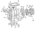
- FIG. 2is an exploded view of washing machine 100 further including a cylindrical wash tub 130 positioned within cabinets 104 , and a motor (not shown) positioned within cabinet 104 .
- Wash tub 130receives basket 107 (shown in FIG. 1 ) rotatably mounted therein, for receiving clothing articles and other fabrics to be washed therein.
- the motordrives basket 107 to rotate around a substantially horizontal axis through a pulley wheel (not shown) and a belt (not shown).
- washing machine 100includes a plurality of water pipes 132 and power lines 134 mounted on rear panel 114 .
- Water pipes 132are coupled in flow communication with wash tub 130 for channeling water into or out of wash tub 130 .
- Power lines 134are electrically connected with the motor (not shown) and other electrical components for providing electric power.
- Washing machine 100also includes a plurality of spaced apart tub suspension elements 136 , such as springs, mounted on top panel 120 or bottom panel 118 , respectively. Each tub suspension element 136 is directly or indirectly attached to wash tub 130 , such that wash tub 130 is suspended within cabinet 104 .
- appliance door 108is coupled to a door panel 144 and is hingedly coupled to front face 112 (shown in FIG. 1 ). Specifically, door 108 is coupled to door panel 144 through a hinge 140 mounted on door panel 144 , and door 108 can be kept at the closed position by a latch 142 also mounted on door panel 144 .
- Door panel 144defines a circular opening 146 therein, a transparent window 148 mounted in opening 146 , a door frame 150 surrounding window 148 , and a door handle 152 mounted thereon.
- door panel 144is substantially rectangular and curves forward from cabinet 104 .
- Door frame 150is substantially ring shaped, and defines a circular opening 154 in the center thereof. Opening 154 is substantially complementary in shape with respect to window 148 such that opening 154 facilitates observing the inside of appliance cavity 106 through window 148 and through the second window ( 180 shown in FIG. 3 ).
- door handle 152includes an arc shaped handle body 160 connected to door frame 150 .
- handle body 160includes a front half 162 integrally formed with door frame 150 , and a rear half 164 coupled with front half 162 by screws.
- handle body 160is a one-piece component integrally formed with door frame 150 .
- door handle 152is attached to door frame 150 by screws, adhesive or other suitable methods known in the art.
- door handle 152is positioned on door panel 144 apart from door frame 150 .
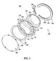
- FIG. 3is an exploded view of appliance door 108 applicable to home appliance 100 (shown in FIG. 2 ).
- Door panel 144(shown in FIG. 2 ) is omitted from FIG. 3 for clarity.
- Handle body 160includes an inner surface 170 (shown in FIG. 2 ) and an outer surface 172 , and handle body 160 extends between two end portions 174 .
- Door handle 152is coupled to door panel 144 and door frame 150 only at end portions 174 , such that door handle 152 defines an access opening 176 between inner surface 170 of handle body 160 and door panel 144 .
- handle body 160also includes a middle portion 178 connected with end portions 174 . As illustrated in FIG. 3 , handle body 160 curves toward an inside of door frame 150 as it extends from end portion 174 to middle portion 178 . In one embodiment, handle body 160 also continuously extends away from door panel 144 (shown in FIG. 2 ) and door frame 150 between end portion 174 and middle portion 178 . As such, the distance between inner surface 170 and door panel 144 gradually enlarges from end portion 174 to middle portion 178 .
- window 148further includes a front glass portion 180 , an inner ring 182 , a rear glass portion 184 , and a back cover 186 .
- Front glass portion 180is circular in shape, and includes a plurality of window latches 188 extending axially from a circumferential edge thereof. Window latches 188 are spaced apart from each other, and each window latch 188 further defines a groove 190 thereon.
- Inner ring 182includes a plurality of tabs 192 radially extending outward from the outer edge thereof and is positioned corresponding to window latches 188 of front glass 180 .
- Rear glass portion 184is circular in shape, and includes a plurality of fastening edges 194 extending radially from a circumferential edge thereof.
- Back cover 186includes a first element 196 and a second element 198 that engages with first element 196 to form an annulus receiving groove 200 therebetween.
- Groove 200is substantially complementary in shape with fastening edge 194 of rear glass 184 .
- FIG. 4is an exploded view of an alternative window 210 applicable to appliance door 108 shown in FIG. 2 .
- window 210is utilized when appliance door 108 is used on a clothes dryer, such as for example, clothes dryer 102 (shown in FIG. 1 ).
- window 210is mounted to door frame 150 (shown in FIG. 3 ) and door panel 144 (shown in FIG. 2 ). It should be recognized, however, that the configuration and location of window 210 may be altered in alternative embodiments.
- window 210includes a circular front glass portion 212 , an inner ring 214 , a rear glass portion 216 , and a back cover 218 .
- Inner ring 214is configured to hold front glass portion 212 , and can be mounted onto the front surface of door frame 150 (shown in FIG. 3 ).
- Rear glass portion 216is substantially semicircular in shape.
- Back cover 218defines an opening 220 substantially complementary in shape with rear glass portion 216 . As such, back cover 218 maintains rear glass portion 216 thereon and is positioned to correspond with opening 220 .
- Back cover 218in one embodiment, is mounted to door panel 144 (shown in FIG. 2 ).
- FIG. 5is an exploded view of a dispenser 230 and a control panel 232 for inclusion on washing machine 100 shown in FIG. 2 .
- FIG. 6is a front view of control panel 232 shown in FIG. 5 .
- Dispenser 230is mounted on an upper left corner of front face 112 , and includes an elongated dispenser base 234 , a dispenser drawer 236 slidably received in dispenser base 234 , and a dispenser panel 238 coupled to a front end of dispenser drawer 236 .
- dispenser base 234includes a water inlet 240 coupled in flow communication with water pipes 132 , and a water outlet 242 coupled in flow communication with wash tub 130 (shown in FIG. 2 ).
- Dispenser drawer 236includes a plurality of longitudinally extending partitioning walls 244 which divide dispenser drawer 236 into several separate compartments 246 .
- Dispenser panel 238defines a slot 248 therein which facilitates sliding dispenser drawer 236 out from and into dispenser base 234 .
- Compartments 246 of dispenser drawer 236enable an operator to add different washing detergents and/or treating agents to different compartments 246 as desired when dispenser drawer 236 slides out.
- wateris optionally channeled from water inlet 240 into the predetermined compartment 246 at the predetermined time upon the operator's selection, and any corresponding treating agent is automatically introduced into wash tub 130 through water outlet 242 .
- control panel 232is electrically connected with power lines 134 (shown in FIG. 2 ), and is coupled to a portion of front face 112 (shown in FIG. 2 ) which extends beyond top panel 120 (shown in FIG. 2 ).
- Control panel 232includes a display 260 , a rotatable knob 262 , a plurality of input selectors 264 , and a mounting bracket 266 for mounting control panel 232 onto cabinet 104 .
- input selectors 264are in the form of touch sensitive buttons, switches or keypads for accessing and selecting appliance features. It is contemplated that other known input selectors may be used in lieu of touch sensitive buttons in alternative embodiments.
- Control panel 232includes a plurality of indicating elements 268 , such as for example, indicating lamps positioned circumferentially around knob 262 , and each indicating element 268 is associated with a corresponding home appliance feature.
- Control panel 232also includes a plurality of signs 270 marked thereon and adjacent to indicating elements 268 for indicating the corresponding appliance features, respectively.
- the selected appliance featurechanges from one to another, and the associated indicating element 268 lights to visually indicate the selected appliance feature.
- the appropriate feature or functionis activated by an appliance controller (not shown) and, for most of the features, an icon or indicator is also displayed on display 260 to visually indicate selected appliance features and operating parameters, such as wash cycles, loading types, etc.
- FIG. 7is a perspective view of base unit 110 applicable to the home appliances shown in FIG. 1 .
- Base unit 110is typically positioned below the home appliance, and includes a storage drawer 272 slidably mounted therein, and a drawer panel 274 coupled to a front end of storage drawer 272 .
- Drawer panel 274further defines a holding slot 276 defined substantially vertically thereon. Holding slot 276 facilitates manipulating drawer 272 sliding into and out of base unit 110 .
- front face 112curves upward and beyond top panel 120 to form ledge 122 , which facilitates preventing items positioned on top panel 120 from falling off.
- an access opening 176 of door handle 152enables an operator's hand to extend between inner surface 170 and door panel 144 , and enables the hand to surround door handle 152 . As such, any finger nails of the hand do not contact the door handle 152 .
Landscapes
- Engineering & Computer Science (AREA)
- Textile Engineering (AREA)
- Main Body Construction Of Washing Machines And Laundry Dryers (AREA)
Abstract
Description
Claims (11)
Priority Applications (2)
| Application Number | Priority Date | Filing Date | Title |
|---|---|---|---|
| US11/240,209US7802855B2 (en) | 2005-09-30 | 2005-09-30 | Home appliance having a door |
| CA2535106ACA2535106C (en) | 2005-09-30 | 2006-02-03 | Methods and apparatus for a home appliance having a door |
Applications Claiming Priority (1)
| Application Number | Priority Date | Filing Date | Title |
|---|---|---|---|
| US11/240,209US7802855B2 (en) | 2005-09-30 | 2005-09-30 | Home appliance having a door |
Publications (2)
| Publication Number | Publication Date |
|---|---|
| US20070075614A1 US20070075614A1 (en) | 2007-04-05 |
| US7802855B2true US7802855B2 (en) | 2010-09-28 |
Family
ID=37901219
Family Applications (1)
| Application Number | Title | Priority Date | Filing Date |
|---|---|---|---|
| US11/240,209Active2025-11-04US7802855B2 (en) | 2005-09-30 | 2005-09-30 | Home appliance having a door |
Country Status (2)
| Country | Link |
|---|---|
| US (1) | US7802855B2 (en) |
| CA (1) | CA2535106C (en) |
Cited By (7)
| Publication number | Priority date | Publication date | Assignee | Title |
|---|---|---|---|---|
| US20100031581A1 (en)* | 2008-08-08 | 2010-02-11 | Lg Electronics Inc. | Door for washing machine |
| US20100077633A1 (en)* | 2008-09-26 | 2010-04-01 | Sang-Hun Bae | Laundry dryer having fragrance storage and supply assembly |
| US20110037363A1 (en)* | 2008-06-03 | 2011-02-17 | Yeon-Sik Choi | Dryer door and dryer comprising the same |
| US20120119630A1 (en)* | 2010-05-19 | 2012-05-17 | Daniel Najera Bernal | Door with Glass Pane for Dryer |
| US9441395B2 (en)* | 2013-07-01 | 2016-09-13 | Samsung Electronics Co., Ltd. | Door and clothes treating apparatus having the same |
| US20180340289A1 (en)* | 2017-04-24 | 2018-11-29 | Miele & Cie. Kg | Door handle for a door of a front-loading household appliance |
| US11242644B2 (en) | 2016-11-21 | 2022-02-08 | Electrolux Appliances Aktiebolag | Door assembly for a laundry treatment machine |
Families Citing this family (17)
| Publication number | Priority date | Publication date | Assignee | Title |
|---|---|---|---|---|
| US8028548B2 (en)* | 2007-05-17 | 2011-10-04 | Lg Electronics Inc. | Laundry machine with height increasing member and drainage filter servicing section |
| CN101970745B (en)* | 2007-05-17 | 2012-12-12 | Lg电子株式会社 | washing machine |
| CN102007243B (en)* | 2007-05-17 | 2014-01-29 | Lg电子株式会社 | laundry machine |
| KR101387522B1 (en)* | 2007-11-05 | 2014-04-23 | 엘지전자 주식회사 | Refrigerator and Controlling method for the same |
| US8215137B2 (en)* | 2007-11-21 | 2012-07-10 | Electrolux Home Products, Inc. | Laundry appliance over-molded metal porthole door frame |
| KR101558903B1 (en)* | 2009-01-12 | 2015-10-08 | 삼성전자 주식회사 | Washing machine and drawer assembly thereof |
| JP4893784B2 (en)* | 2009-06-22 | 2012-03-07 | パナソニック株式会社 | Drum washing machine |
| US9212449B2 (en) | 2010-08-31 | 2015-12-15 | Bsh Home Appliances Corporation | Structural door bowl for a household appliance door |
| EP2740833B1 (en)* | 2012-12-06 | 2017-04-12 | Electrolux Home Products Corporation N.V. | Laundry treatment device with door assembly |
| KR102375906B1 (en)* | 2013-07-01 | 2022-03-18 | 삼성전자주식회사 | Door and clothes treating apparatus having the same |
| US12287962B2 (en)* | 2013-09-03 | 2025-04-29 | Apple Inc. | User interface for manipulating user interface objects |
| EP3147747A1 (en) | 2014-06-27 | 2017-03-29 | Apple Inc. | Manipulation of calendar application in device with touch screen |
| DE102016222256A1 (en)* | 2016-11-14 | 2018-05-17 | BSH Hausgeräte GmbH | Household appliance with projection device and method for its operation |
| EP3323928B1 (en)* | 2016-11-21 | 2023-08-30 | Electrolux Appliances Aktiebolag | A door assembly for a laundry treating machine and a method to modify the position of a handle in said door assembly |
| EP3323927B1 (en)* | 2016-11-21 | 2021-11-10 | Electrolux Appliances Aktiebolag | A door assembly for a laundry treating machine |
| DE102020211705A1 (en)* | 2020-09-18 | 2022-03-24 | BSH Hausgeräte GmbH | Door unit for closing an opening in a laundry care appliance |
| US12000074B2 (en)* | 2021-12-20 | 2024-06-04 | Whirlpool Corporation | Laundry treating appliance with a panel |
Citations (22)
| Publication number | Priority date | Publication date | Assignee | Title |
|---|---|---|---|---|
| US946317A (en)* | 1909-04-20 | 1910-01-11 | Burns & Bassick Co | Handle for drawers. |
| US2118582A (en)* | 1935-06-27 | 1938-05-24 | Prosperity Co Inc | Laundry washing machine |
| US2317213A (en)* | 1939-06-30 | 1943-04-20 | Bendix Home Appliances Inc | Cleaning machine |
| US2587645A (en)* | 1946-05-09 | 1952-03-04 | Hamilton Mfg Co | Laundry drier |
| US2722119A (en)* | 1954-02-17 | 1955-11-01 | Arthur R Constantine | Door construction for tumbler type washing machines |
| US3899204A (en) | 1973-09-26 | 1975-08-12 | Carl Ulrich | Washing machine and door latch |
| US4934559A (en)* | 1989-06-08 | 1990-06-19 | Speed Queen Company | Door bar handle for glass door of clothes dryer |
| US5195647A (en)* | 1991-03-29 | 1993-03-23 | Raytheon Company | Clothes dryer door assembly and method for reversing mounting side |
| US6057534A (en)* | 1997-12-31 | 2000-05-02 | Samsung Electronics Co., Ltd. | Door for a microwave oven having a knob part convenient to grasp |
| USD450164S1 (en)* | 2000-03-01 | 2001-11-06 | Notetry Limited | Washing machine |
| USD459037S1 (en)* | 2001-02-08 | 2002-06-18 | Maytag Corporation | Portable laundry device |
| USD459844S1 (en)* | 2001-05-31 | 2002-07-02 | Whirlpool Corporation | Laundry appliance front panel |
| US6560998B2 (en)* | 2001-08-30 | 2003-05-13 | Maytag Corporation | Door boot with reduced opening force |
| US20030172689A1 (en)* | 2000-09-16 | 2003-09-18 | Fitton Nicholas Gerald | Laundry appliance |
| US20040020246A1 (en)* | 2002-07-31 | 2004-02-05 | Yun Ju Hwan | Door on drum type washing machine or laundry dryer |
| US20040089031A1 (en) | 2002-01-09 | 2004-05-13 | Kim Jong Seok | Door and a drum type washing machine and a clothes dryer using the same |
| US20050262887A1 (en) | 2004-06-01 | 2005-12-01 | Lg Electronics Inc. | Door assembly for washing machine |
| US20050268667A1 (en)* | 2004-06-07 | 2005-12-08 | Lg Electronics Inc. | Drum washing machine |
| USD518250S1 (en)* | 2004-05-26 | 2006-03-28 | Whirlpool Corporation | Dryer |
| USD524001S1 (en)* | 2005-08-08 | 2006-06-27 | Whirlpool Corporation | Laundry appliance |
| US20060265959A1 (en)* | 2005-05-30 | 2006-11-30 | Mabe Canada Inc. | Clothes dryer reversible door assembly |
| US20070051012A1 (en)* | 2005-09-02 | 2007-03-08 | Bsh Home Appliances Corporation | Appliance door having see-through portion |
- 2005
- 2005-09-30USUS11/240,209patent/US7802855B2/enactiveActive
- 2006
- 2006-02-03CACA2535106Apatent/CA2535106C/enactiveActive
Patent Citations (22)
| Publication number | Priority date | Publication date | Assignee | Title |
|---|---|---|---|---|
| US946317A (en)* | 1909-04-20 | 1910-01-11 | Burns & Bassick Co | Handle for drawers. |
| US2118582A (en)* | 1935-06-27 | 1938-05-24 | Prosperity Co Inc | Laundry washing machine |
| US2317213A (en)* | 1939-06-30 | 1943-04-20 | Bendix Home Appliances Inc | Cleaning machine |
| US2587645A (en)* | 1946-05-09 | 1952-03-04 | Hamilton Mfg Co | Laundry drier |
| US2722119A (en)* | 1954-02-17 | 1955-11-01 | Arthur R Constantine | Door construction for tumbler type washing machines |
| US3899204A (en) | 1973-09-26 | 1975-08-12 | Carl Ulrich | Washing machine and door latch |
| US4934559A (en)* | 1989-06-08 | 1990-06-19 | Speed Queen Company | Door bar handle for glass door of clothes dryer |
| US5195647A (en)* | 1991-03-29 | 1993-03-23 | Raytheon Company | Clothes dryer door assembly and method for reversing mounting side |
| US6057534A (en)* | 1997-12-31 | 2000-05-02 | Samsung Electronics Co., Ltd. | Door for a microwave oven having a knob part convenient to grasp |
| USD450164S1 (en)* | 2000-03-01 | 2001-11-06 | Notetry Limited | Washing machine |
| US20030172689A1 (en)* | 2000-09-16 | 2003-09-18 | Fitton Nicholas Gerald | Laundry appliance |
| USD459037S1 (en)* | 2001-02-08 | 2002-06-18 | Maytag Corporation | Portable laundry device |
| USD459844S1 (en)* | 2001-05-31 | 2002-07-02 | Whirlpool Corporation | Laundry appliance front panel |
| US6560998B2 (en)* | 2001-08-30 | 2003-05-13 | Maytag Corporation | Door boot with reduced opening force |
| US20040089031A1 (en) | 2002-01-09 | 2004-05-13 | Kim Jong Seok | Door and a drum type washing machine and a clothes dryer using the same |
| US20040020246A1 (en)* | 2002-07-31 | 2004-02-05 | Yun Ju Hwan | Door on drum type washing machine or laundry dryer |
| USD518250S1 (en)* | 2004-05-26 | 2006-03-28 | Whirlpool Corporation | Dryer |
| US20050262887A1 (en) | 2004-06-01 | 2005-12-01 | Lg Electronics Inc. | Door assembly for washing machine |
| US20050268667A1 (en)* | 2004-06-07 | 2005-12-08 | Lg Electronics Inc. | Drum washing machine |
| US20060265959A1 (en)* | 2005-05-30 | 2006-11-30 | Mabe Canada Inc. | Clothes dryer reversible door assembly |
| USD524001S1 (en)* | 2005-08-08 | 2006-06-27 | Whirlpool Corporation | Laundry appliance |
| US20070051012A1 (en)* | 2005-09-02 | 2007-03-08 | Bsh Home Appliances Corporation | Appliance door having see-through portion |
Cited By (15)
| Publication number | Priority date | Publication date | Assignee | Title |
|---|---|---|---|---|
| US20110037363A1 (en)* | 2008-06-03 | 2011-02-17 | Yeon-Sik Choi | Dryer door and dryer comprising the same |
| US8607473B2 (en)* | 2008-06-03 | 2013-12-17 | Lg Electronics Inc. | Dryer door and dryer comprising the same |
| US20100031581A1 (en)* | 2008-08-08 | 2010-02-11 | Lg Electronics Inc. | Door for washing machine |
| US8151603B2 (en)* | 2008-08-08 | 2012-04-10 | Lg Electronics Inc. | Door for washing machine |
| US20100077633A1 (en)* | 2008-09-26 | 2010-04-01 | Sang-Hun Bae | Laundry dryer having fragrance storage and supply assembly |
| US8336227B2 (en)* | 2008-09-26 | 2012-12-25 | Lg Electronics Inc. | Laundry dryer having fragrance storage and supply assembly |
| US8523300B2 (en)* | 2010-05-19 | 2013-09-03 | Mabe, S.A. De C.V. | Door with glass pane for dryer |
| US20120119630A1 (en)* | 2010-05-19 | 2012-05-17 | Daniel Najera Bernal | Door with Glass Pane for Dryer |
| US8757741B2 (en) | 2010-05-19 | 2014-06-24 | Mabe, S.A. De C.V. | Door with glass pane for dryer |
| US9441395B2 (en)* | 2013-07-01 | 2016-09-13 | Samsung Electronics Co., Ltd. | Door and clothes treating apparatus having the same |
| US20160340820A1 (en)* | 2013-07-01 | 2016-11-24 | Samsung Electronics Co., Ltd. | Door and clothes treating apparatus having the same |
| US10563340B2 (en)* | 2013-07-01 | 2020-02-18 | Samsung Electronics Co., Ltd. | Door and clothes treating apparatus having the same |
| US11242644B2 (en) | 2016-11-21 | 2022-02-08 | Electrolux Appliances Aktiebolag | Door assembly for a laundry treatment machine |
| US20180340289A1 (en)* | 2017-04-24 | 2018-11-29 | Miele & Cie. Kg | Door handle for a door of a front-loading household appliance |
| US10465330B2 (en)* | 2017-04-24 | 2019-11-05 | Miele & Cie. Kg | Door handle for a door of a front-loading household appliance |
Also Published As
| Publication number | Publication date |
|---|---|
| CA2535106C (en) | 2013-10-08 |
| CA2535106A1 (en) | 2007-03-30 |
| US20070075614A1 (en) | 2007-04-05 |
Similar Documents
| Publication | Publication Date | Title |
|---|---|---|
| CA2535106C (en) | Methods and apparatus for a home appliance having a door | |
| EP2063014B1 (en) | Washing machine | |
| EP2063013B1 (en) | Washing machine | |
| EP3135800B1 (en) | Auxiliary washing machine | |
| EP2586902B1 (en) | Laundry treating apparatus | |
| KR101830733B1 (en) | Laundry Machine | |
| AU2017204095B2 (en) | Laundry treating apparatus and method of the same | |
| US8857928B2 (en) | Appliance with a bracket for supporting a hinge | |
| WO2011128745A2 (en) | Fully openable multifunction drawer for household appliances | |
| US20120036900A1 (en) | Washing machine | |
| US20130232810A1 (en) | Door handle for a washing machine or dryer appliance | |
| EP3339495B1 (en) | Washing machine and method for controlling the same | |
| EP2238285B1 (en) | A washer/dryer | |
| WO2015028245A1 (en) | Door assembly for a laundry treatment device | |
| CN107429467B (en) | Clothes treating appliance | |
| AU2009201721B2 (en) | Laundry machine | |
| WO2015028239A1 (en) | Door assembly for a laundry treatment device | |
| US20130180123A1 (en) | Appliance having a drying rack | |
| KR102257624B1 (en) | Laundry treating apparatus | |
| RU2713372C1 (en) | Home appliance with movable control panel and method of such device operation | |
| CA2664471C (en) | Washing machine | |
| EP1598472A1 (en) | Washing machine | |
| US20120255328A1 (en) | Magnifying door for a washing machine appliance | |
| KR20160042413A (en) | Laundry Machine |
Legal Events
| Date | Code | Title | Description |
|---|---|---|---|
| AS | Assignment | Owner name:GENERAL ELECTRIC COMPANY, NEW YORK Free format text:ASSIGNMENT OF ASSIGNORS INTEREST;ASSIGNOR:CALMEISE, RANDALL W.;REEL/FRAME:017077/0169 Effective date:20050930 | |
| FEPP | Fee payment procedure | Free format text:PAYOR NUMBER ASSIGNED (ORIGINAL EVENT CODE: ASPN); ENTITY STATUS OF PATENT OWNER: LARGE ENTITY | |
| STCF | Information on status: patent grant | Free format text:PATENTED CASE | |
| FPAY | Fee payment | Year of fee payment:4 | |
| AS | Assignment | Owner name:HAIER US APPLIANCE SOLUTIONS, INC., DELAWARE Free format text:ASSIGNMENT OF ASSIGNORS INTEREST;ASSIGNOR:GENERAL ELECTRIC COMPANY;REEL/FRAME:038966/0120 Effective date:20160606 | |
| MAFP | Maintenance fee payment | Free format text:PAYMENT OF MAINTENANCE FEE, 8TH YEAR, LARGE ENTITY (ORIGINAL EVENT CODE: M1552) Year of fee payment:8 | |
| MAFP | Maintenance fee payment | Free format text:PAYMENT OF MAINTENANCE FEE, 12TH YEAR, LARGE ENTITY (ORIGINAL EVENT CODE: M1553); ENTITY STATUS OF PATENT OWNER: LARGE ENTITY Year of fee payment:12 |