US7802630B2 - Fire-fighting monitor - Google Patents
Fire-fighting monitorDownload PDFInfo
- Publication number
- US7802630B2 US7802630B2US12/163,330US16333008AUS7802630B2US 7802630 B2US7802630 B2US 7802630B2US 16333008 AUS16333008 AUS 16333008AUS 7802630 B2US7802630 B2US 7802630B2
- Authority
- US
- United States
- Prior art keywords
- base
- fire
- outlet
- actuator
- fluid path
- Prior art date
- Legal status (The legal status is an assumption and is not a legal conclusion. Google has not performed a legal analysis and makes no representation as to the accuracy of the status listed.)
- Active
Links
- 239000012530fluidSubstances0.000claimsabstractdescription50
- 229910001369BrassInorganic materials0.000description2
- 230000008901benefitEffects0.000description2
- 239000010951brassSubstances0.000description2
- 238000004519manufacturing processMethods0.000description2
- 229920001343polytetrafluoroethylenePolymers0.000description2
- 239000004810polytetrafluoroethyleneSubstances0.000description2
- XLYOFNOQVPJJNP-UHFFFAOYSA-NwaterSubstancesOXLYOFNOQVPJJNP-UHFFFAOYSA-N0.000description2
- 239000006260foamSubstances0.000description1
- 239000004519greaseSubstances0.000description1
- 239000000314lubricantSubstances0.000description1
- -1polytetrafluoroethylenePolymers0.000description1
- 239000012260resinous materialSubstances0.000description1
Images


Classifications
- A—HUMAN NECESSITIES
- A62—LIFE-SAVING; FIRE-FIGHTING
- A62C—FIRE-FIGHTING
- A62C31/00—Delivery of fire-extinguishing material
- A62C31/02—Nozzles specially adapted for fire-extinguishing
- B—PERFORMING OPERATIONS; TRANSPORTING
- B05—SPRAYING OR ATOMISING IN GENERAL; APPLYING FLUENT MATERIALS TO SURFACES, IN GENERAL
- B05B—SPRAYING APPARATUS; ATOMISING APPARATUS; NOZZLES
- B05B15/00—Details of spraying plant or spraying apparatus not otherwise provided for; Accessories
- B05B15/60—Arrangements for mounting, supporting or holding spraying apparatus
- B05B15/65—Mounting arrangements for fluid connection of the spraying apparatus or its outlets to flow conduits
- B05B15/652—Mounting arrangements for fluid connection of the spraying apparatus or its outlets to flow conduits whereby the jet can be oriented
Definitions
- the present inventionis directed to a fire-fighting monitor and, more specifically, to a fire-fighting monitor that is flexible and configurable into a compact stowage configuration.
- Fire-fighting monitorsare used to direct the flow of water or other fire-fighting fluid and include an inlet, which is connected to a hose or pipe, and a discharge outlet to which a nozzle or stream-shaper is mounted. Monitors are typically mounted to fire-fighting vehicles and/or aerial ladders and deliver a large quantity of fluid (typically water or foam) either directly to a fire, or to a fire via a hose or other conduit. Typical monitors are made up of curved and straight pipes or conduits, some of which may be rotatably or rigidly mounted to one another, and commonly include curves in different directions, which reduces flow efficiency.
- typical monitorsprovide limited directional control over the fluid that they convey, by rotating about a single vertical pivot axis and pivoting about one or two horizontal axes for elevational change, and can significantly reduce the fluid flow energy by causing abrupt or multiple changes in flow direction.
- Typical monitorsmay also include a relatively large number of different parts, adding cost and complexity.
- monitorstypically have little flexibility, they occupy a relatively large amount of horizontal and vertical space when not in use, and can exhibit a large swing radius when rotated.
- typical monitorsmay prevent vehicles to which they are attached from being stored in certain garages or from passing through low-clearance areas, and may reduce the space available for other equipment in the vicinity of the monitor, for example. Therefore, there is a need to provide a monitor having improved flexibility and reduced proportions when stowed.
- the present inventionprovides a fire-fighting monitor that is adapted to flex along a substantial portion of its length to control the direction of fluid flow through the monitor, to provide an efficient fluid path through the monitor, to require a relatively small stowage space, and to do so with a relatively simple and inexpensive design.
- a fire-fighting monitorin one form of the invention, includes a base, an outlet, a plurality of hollow members, and one or more joints at the hollow members.
- the hollow membersare connected in series between the base and the outlet to provide a flexible fluid path, and include a base-end hollow member, which is coupled to the base, and an outlet-end hollow member, which forms the outlet.
- Each of the hollow membershas a ball portion and a socket portion, with the socket portions adapted to receive the ball portions.
- the joints of the fire-fighting monitorinclude hinges or ball-joints.
- the fire-fighting monitorcomprises a seal at each of the socket portions of the hollow members.
- the sealsengage the ball portions of the hollow members to provide a substantially fluid-tight seal between adjacent hollow members.
- the fire-fighting monitorfurther incorporates an actuator having a first end coupled to the base and a second end coupled to the outlet.
- the actuatoris actuatable to move the outlet relative to the base.
- the fire-fighting monitorfurther comprises rotary actuators at the joints for moving the outlet relative to the base.
- the base of the fire-fighting monitoris rotatable, and may be drivable by a powered drive unit, for example.
- a fire-fighting monitorin another form of the invention, includes two or more hollow members pivotally connected to one another in series between a base and an outlet.
- An actuatoris coupled between the base and the outlet, whereby actuating the actuator pivots the hollow members and repositions the outlet relative to the base.
- the actuatoris actuatable so that the outlet is substantially aligned with the base to define a substantially straight fluid path, and is further actuatable to form a curved fluid path.
- the actuatoris actuatable until the outlet is oriented at least about 135 degrees from the base.
- the outletis repositionable to form either a straight fluid path through the monitor, or a curved fluid path through the monitor.
- each hollow memberis pivotable about a pivot axis relative to an adjacent hollow member, wherein the pivot axes of the hollow members are substantially parallel to one another.
- the monitor of the present inventionprovides a monitor with improved flexibility, higher flow-efficiency, smaller stowage size, and relatively low complexity.
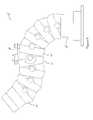
- FIG. 1is a perspective view of a monitor of the present invention in a stowage configuration
- FIG. 2is a side elevation of the monitor of FIG. 1 ;
- FIG. 3is a cross-section view of the monitor of FIG. 2 ;
- FIG. 4is an elevation view of the monitor in a raised position
- FIG. 5is a sectional view of the monitor taken along the section designated V-V in FIG. 4 ;
- FIG. 6is a side elevation of the monitor defining a two-curve fluid path and having a segment actuator
- FIG. 7is a cross-section view of an alternative embodiment base useful with a monitor of the present invention.
- FIG. 8is a partial sectional view of another alternative embodiment base useful with a monitor of the present invention.
- the numeral 1 0generally designates a fire-fighting monitor of the present invention.
- monitor 10is adapted to exhibit increased flexibility, an efficient fluid path, and a compact stowage configuration.
- monitor 10includes a base 12 defining an inlet, an outlet 14 , and a plurality of hollow members 16 arranged in series between base 12 and outlet 14 .
- Each hollow member 16is coupled or connected to an adjacent hollow member 16 via a pair of joints 18 , each pair of joints providing a pivot axis.
- one hollow memberis coupled or connected to base 12 and another hollow member is coupled or connected to a hollow member configured as an outlet 14 to thereby form a flexible monitor body that extends from the base to the outlet.
- the hollow membersare pivotally mounted to one another in series about a plurality of pivot axes to form a straight fluid path ( FIGS. 4 and 5 ) or a fluid path with a single bend ( FIGS. 1-3 ), although as will be more fully described below, monitor 10 is not limited to straight or single-curve fluid paths, and may be configured to form two or more curves or bends ( FIG. 6 ).
- the pivot axes formed by joints 18are generally parallel such that a single actuator may be used to reconfigure the flexible monitor body and further reposition the outlet.
- an actuator 20may be provided to control the vertical or elevational aiming of outlet 14 of monitor 10 .
- hollow members 16include ball portions 16 a and socket portions 16 b .
- Each ball portion 16 ahas an arcuate outer surface whose center of curvature is offset from the center of curvature of the arcuate surface of the corresponding socket portion 16 b of a given hollow member 16 . Further, the arcuate surface of each ball portion abuts or is adjacent the arcuate surface of its respective socket portion so that the juncture of the two arcuate surfaces forms a limit or stop, as described below.
- Socket portion 16 b of a given hollow memberis adapted to receive ball portion 16 a of an immediately adjacent hollow member to provide a nested or overlapping arrangement between each adjacent hollow member.
- the degree of flex of monitor 10is limited when a terminal edge 16 b ′ of the socket portion 16 b of one hollow member abuts a base 16 b ′′ of the arcuate surface of the socket portion 16 b of an adjacent hollow member 16 , which acts as a stop or limiter.
- the degree of flex of monitor 10is limited when a terminal edge 14 b ′ of socket portion 14 b of outlet 14 contacts the base 16 b ′′ of socket portion 16 b of the adjacent hollow member 16 .
- Annular seals 22FIG.
- Base 12includes an annular base flange 24 and a base member 26 coupled to the base flange.
- Base flange 24is coupled to a fluid pressure source, such as a fire-fighting vehicle, and holds base member 26 in a longitudinally fixed position relative to the pressure source.
- Base member 26includes a ball portion 26 a having substantially the same outer dimensions as ball portions 16 a of hollow members 16 , and is therefore configured for socket portion 16 b of the hollow member 16 located at the base end of monitor 10 to be disposed thereon.
- base member 26includes a mounting element 30 that extends radially outward from base member 26 for receiving actuator 20 .
- a mounting flange 26 c of base member 26is cooperatively received in a corresponding annular channel 24 a of base flange 24 to fasten base member 26 thereto.
- Base member 26may be rotatable relative to base flange 24 to facilitate control over the flow direction of fire-fighting fluid out of outlet 14 .
- ball bearings or a bushingmay be provided between base member 26 and base flange 24 , to facilitate rotation and directional aiming of base member 26 .
- a tubular sleeve or hollow cylindersuch as a sleeve made of a polytetrafluoroethylene (PTFE) or other resinous material, may be inserted between base member 26 and base flange 24 , to facilitate rotation of base member 26 .
- PTFEpolytetrafluoroethylene
- the base flangemay include a latch mechanism for removably attaching the monitor to a fire-fighting vehicle or other mounting surface, such as the latch mechanism described in commonly assigned U.S. Pat. No. 6,786,426, which is hereby incorporated herein by reference in its entirety.
- outlet 14includes a socket portion 14 b for receiving the ball portion of the hollow member that is at the outlet end of monitor 10 .
- An annular seal 22is also included at an inner surface 31 of socket portion 14 b of outlet 14 to provide a fluid-tight seal between socket portion 14 b and ball portion 16 a .
- Outlet 14further incorporates a threaded end portion 14 a for mounting a nozzle 28 (shown in phantom in FIG. 2 ) to monitor 10 , or for threadably receiving a conduit such as a hose or pipe.
- Outlet 14also includes an actuator mounting element 32 for receiving actuator 20 , described below.
- Joints 18are provided at opposite sides of socket portions 16 b and socket portion 14 b , as best seen in FIGS. 1 , 2 , and 5 . Each joint 18 forms a pivotable connection between socket portion 16 b and ball portion 16 a , or between socket portion 14 b and ball portion 16 a . Joints 18 also connect the hollow member closest to base 12 to ball portion 26 a of base member 26 . Joints 18 may comprise, for example, ball-and-socket joints, pin-and-bore joints, or the like. In the illustrated embodiment, joints 18 are pivot bolts having generally cylindrical pivot portions 18 a that are received by bores in socket portions 16 b and cavities in ball portions 16 a ( FIG. 5 ).
- distal end portions of pivot portions 18 amay be threaded for engaging corresponding threads in the cavities of ball portions 16 a , while proximal end portions of pivot portions 18 a may be smooth for pivoting within smooth bores of socket portions 16 b .
- proximal end portions of pivot portions 18 amay be threaded for engaging corresponding threads in the bores of socket portions 16 b
- distal end portions of pivot portions 18 amay be smooth for pivoting within smooth cavities in ball portions 16 a .
- a joint incorporating a one-way clutchthat may be useful with the present invention, see U.S. patent application Ser. No. 10/962,271, which is commonly assigned to Elkhart Brass Manufacturing Company, Inc., and which is hereby incorporated herein by reference in its entirety.
- Actuator 20is pivotally coupled to mounting element 30 at base member 26 , and is further coupled to mounting element 32 at outlet 14 . Extension and retraction of actuator 20 causes outlet 14 and hollow members 16 to pivot relative to one another at joints 18 and move relative to base 12 in a substantially vertical plane. In this manner, the fluid passage or fluid path through the flexible monitor body may have a varying radius of curvature. For example, when actuator 20 is fully retracted, actuator mounting elements 30 , 32 are drawn toward one another to form a relatively small radius of curvature so that monitor 10 is in a relatively compact stowage configuration and/or may direct fluid downwardly ( FIGS. 1-3 ).
- actuator 20When actuator 20 is extended, actuator mounting elements 30 , 32 are urged away from one another to direct outlet 14 upwardly, and may be extended to direct fluid substantially vertically, as best seen in FIGS. 4 and 5 .
- the outletWhen actuator 20 is further extended, the outlet may be aimed at least somewhat in a direction opposite to the aiming direction when actuator 20 is retracted.
- the actuatormay be operable to extend outlet 14 substantially beyond vertical or backwards, and/or to retract or lower the outlet substantially below approximately 45 degrees from a horizontal reference (or approximately 135 degrees from a vertical reference or the fluid input direction), such as for stowage.
- the monitormay thus be positioned at substantially any curve radius ranging between the radius at the stowage position and an infinite-radius curve or straight line fluid path.
- a linkage(not shown), such as a four-bar linkage or the like, may be used in combination with the actuator to enhance the mechanical leverage of the actuator, to improve the aiming precision, and/or to increase the effective vertical range of motion of monitor 10 .
- Actuator 20may comprise an electric actuator, a hydraulic actuator, a ball screw actuator, a manually-driven actuator, a belt or chain system, or the like, for example.
- a pivoting actuatormay be provided to move outlet 14 relative to base member 26 by applying a moment force.
- each joint 18may be equipped with a rotary actuator such as an electric or hydraulic motor.
- Actuator 20may include a pivoting control (not shown) at one or both of mounting elements 30 , 32 , which pivoting control is driven by an electric or hydraulic motor to change the orientation of actuator 20 and thus change the position and orientation of outlet 14 .
- Such a pivoting controlmay be selectively operated in combination with the linear adjustment of actuator 20 , or operated independently.
- the hollow membersmay define a fluid path having single bend in a first direction, while the outlet or a nozzle thereon is aimed by the pivoting control to define another bend in the fluid path in a second direction.
- a monitor 10 ′may include one or more actuators 20 ′ pivotally coupled to adjacent hollow members 16 ′ for pivoting the adjacent hollow members about their joints 18 .
- one of actuators 20 ′may be connected between each adjacent pair of hollow members to facilitate individual control over the orientation of each hollow member relative to the adjacent hollow member (or an outlet 14 ′ or base member 26 ′).
- the hollow members 16 ′may be adjusted to position the outlet 14 ′ as desired, and/or to position the monitor body to define a fluid path having one or more curves.
- the monitormay be mounted to a base 112 with a base flange 124 and a base member 126 .
- Base flange 124includes a generally flat radially-extending flange portion 124 a and an upwardly-extending cylindrical portion 124 b .
- Base member 126is a generally cylindrical sleeve that mounts over the upwardly-extending cylindrical portion 124 b of base flange 124 .
- Cylindrical portion 124 b of base flange 124may include one or more annular grooves 134 along an outer surface to provide a portion of a bearing race.
- Base member 126includes corresponding annular grooves 136 to provide another portion of the bearing race.
- Grooves 134 , 136cooperate to form annular passageways when base member 126 is assembled onto base flange 124 , the passageways for receiving a plurality of ball bearings 138 to facilitate rotation of base member 126 relative to base flange 124 .
- Access to the passagewaysmay be provided through access holes 140 in base member 126 , the access holes being selectively closeable with set screws 142 or the like.
- a grease fitting 144may be provided at base member 126 to facilitate the introduction of lubricants between base member 126 and base flange 124 , and onto bearings 138 .
- a seal 122substantially prevents fire-fighting fluid from entering between base flange 124 and base member 126 .
- the monitormay be mounted to another embodiment of a base 212 that includes a base flange 224 and a base member 226 .
- Base flange 224includes a generally flat flange portion 224 a and an upwardly-extending cylindrical portion 224 b .
- Base member 226is a generally cylindrical sleeve that mounts inside the upwardly-extending cylindrical portion 224 b of base flange 224 .
- Base 212includes a drive unit 246 for rotatably driving base member 226 relative to base flange 224 .
- drive unit 246comprises an electric drive motor with a manual override knob 248 .
- Drive unit 246is mounted to base flange 224 and is operable to turn a worm (not shown) that engages a worm gear 250 in the outer surface of base member 226 to thereby rotatably drive base member 226 .
- Override knob 248may be rotated to manually drive the worm and rotate base member 226 .
- Base member 226may be rotated through 360 degrees about a vertical axis via drive unit 246 or, optionally, may have its rotation limited by one or more stops 252 that are inserted through base flange 224 and into channels 254 in the outer surface of base member 226 .
- Drive unit 246may include an electric motor, a hydraulic motor, or the like. Suitable drive units are more fully described in commonly assigned U.S. Pat. No. 6,994,282, which is hereby incorporated herein by reference in its entirety.
- a tiller handle or a manual hand wheelmay be provided at any of base members 26 , 126 , 226 for rotating the base member.
- Other drive units that may be suitable for use to rotatably drive the monitorinclude a fire-fighting monitor with remote control such as that disclosed in commonly assigned U.S. Pat. No. 7,191,964, which is hereby incorporated herein by reference in its entirety.
- the present inventionprovides a fire-fighting monitor with a flow-efficient fluid path, a large range of flexibility of the monitor in a vertical plane, a relatively small stowage size, and 360 degree rotational capability.
- monitor 10may be mounted to a substantially vertical surface such that fluid flow through the base is substantially horizontal.
- monitor 10may be oriented in substantially any orientation on a vehicle, or on a portable mount or stand or the like.
- monitor 10includes seven hollow members 16 arranged between base member 26 and outlet 14 .
- additional hollow membersmay be provided to increase the length and/or to increase the degree of flexibility of the monitor.
- hollow membersmay be removed to reduce the length and degree of flexibility as desired.
- pivot axes of the jointare illustrated as being substantially parallel, the pivot axes of the joints may be non-parallel, such that the flexible monitor forms a helical shape, or other curved shape, when in a curved or stowed position.
Landscapes
- Health & Medical Sciences (AREA)
- Public Health (AREA)
- Business, Economics & Management (AREA)
- Emergency Management (AREA)
- Fire-Extinguishing By Fire Departments, And Fire-Extinguishing Equipment And Control Thereof (AREA)
Abstract
Description
Claims (22)
Priority Applications (1)
| Application Number | Priority Date | Filing Date | Title |
|---|---|---|---|
| US12/163,330US7802630B2 (en) | 2007-06-29 | 2008-06-27 | Fire-fighting monitor |
Applications Claiming Priority (2)
| Application Number | Priority Date | Filing Date | Title |
|---|---|---|---|
| US94718807P | 2007-06-29 | 2007-06-29 | |
| US12/163,330US7802630B2 (en) | 2007-06-29 | 2008-06-27 | Fire-fighting monitor |
Publications (2)
| Publication Number | Publication Date |
|---|---|
| US20090000795A1 US20090000795A1 (en) | 2009-01-01 |
| US7802630B2true US7802630B2 (en) | 2010-09-28 |
Family
ID=40159005
Family Applications (1)
| Application Number | Title | Priority Date | Filing Date |
|---|---|---|---|
| US12/163,330ActiveUS7802630B2 (en) | 2007-06-29 | 2008-06-27 | Fire-fighting monitor |
Country Status (2)
| Country | Link |
|---|---|
| US (1) | US7802630B2 (en) |
| WO (1) | WO2009006308A1 (en) |
Cited By (7)
| Publication number | Priority date | Publication date | Assignee | Title |
|---|---|---|---|---|
| US20090277656A1 (en)* | 2008-05-09 | 2009-11-12 | Elkhart Brass Manufacturing Company, Inc. | Compact fire fighting monitor |
| WO2012061868A1 (en)* | 2010-11-08 | 2012-05-18 | Pandeb Holdings Pty Ltd | An irrigation system |
| US20140034338A1 (en)* | 2012-04-12 | 2014-02-06 | Task Force Tips, Incorporated | Pivoting Fluid Conduit Sequencing Mechanism |
| US9138754B2 (en) | 2012-03-27 | 2015-09-22 | Task Force Tips, Incorporated | Adjustable firefighting nozzle |
| US9675826B2 (en) | 2012-06-22 | 2017-06-13 | Akron Brass Company | Positionable outlet for a water monitor |
| US10072780B2 (en) | 2012-08-17 | 2018-09-11 | Elkhart Brass Manufacturing Company, Inc. | Fluid delivery device |
| USRE48069E1 (en) | 2003-04-02 | 2020-06-30 | Elkhart Brass Manufacturing Company, Llc | Fire-fighting monitor with remote control |
Families Citing this family (2)
| Publication number | Priority date | Publication date | Assignee | Title |
|---|---|---|---|---|
| US8944346B2 (en)* | 2010-01-04 | 2015-02-03 | Akron Brass Company | Rotatable flange for a water monitor |
| CN111167057B (en)* | 2020-02-21 | 2021-06-01 | 南京幸庄科技创新产业园管理有限公司 | Fire-fighting lance mount |
Citations (33)
| Publication number | Priority date | Publication date | Assignee | Title |
|---|---|---|---|---|
| US167505A (en) | 1875-09-07 | Improvement in joints for hydraulic nozzles | ||
| US557799A (en) | 1896-04-07 | Adjustable nozzle for hose-pipes | ||
| US978107A (en) | 1910-01-24 | 1910-12-06 | Seneca L Berry | Hydraulic giant. |
| US1599907A (en) | 1925-07-20 | 1926-09-14 | Macgregor Wallace | Swing joint |
| US1665810A (en) | 1920-07-26 | 1928-04-10 | Vapor Car Heating Co Inc | Flexible joint |
| US2111553A (en) | 1936-10-15 | 1938-03-22 | Chew Yee Lain | Mining monitor or nozzle |
| GB485161A (en) | 1936-11-11 | 1938-05-11 | Otto Sekinger | Improvements in automatic distant-controlled fire extinguishing systems |
| US2342757A (en) | 1940-04-20 | 1944-02-29 | Leslie W Roser | Nozzle |
| US3106247A (en) | 1962-03-26 | 1963-10-08 | Lacks Hyman | Fire fighting apparatus |
| JPS427756Y1 (en) | 1965-01-20 | 1967-04-17 | ||
| JPS427757Y1 (en) | 1965-01-20 | 1967-04-17 | ||
| DE1425515A1 (en) | 1963-03-21 | 1969-12-04 | Metallgesellschaft Ag | Device for connecting fixed and movable pipe sockets |
| DE1945523A1 (en) | 1969-09-09 | 1971-03-11 | Martin Herter | Ball joint pipe connection |
| DE1952689A1 (en) | 1969-10-20 | 1971-05-06 | Maschinefabriek Holleman Nv | Device for delivering a stream of material at a variable angle |
| DE6940725U (en) | 1969-10-23 | 1971-08-12 | Masch Fabriek Holleman Nv | DEVICE FOR DELIVERING A FLOW OF MATERIAL AT A VARIABLE ANGLE. |
| JPS55146158A (en) | 1979-02-21 | 1980-11-14 | Alpha Therapeutic Corp | Collecting vessel for sterilized liquid and its joining method |
| US4350297A (en) | 1961-07-05 | 1982-09-21 | Frank Martin | Swivelling exhaust nozzles for rocket motors |
| US4392618A (en) | 1980-03-13 | 1983-07-12 | Chubb Fire Security Limited | Liquid-projecting monitor |
| US4674686A (en) | 1984-09-28 | 1987-06-23 | Elkhart Brass Manufacturing Co., Inc. | Portable fire apparatus monitor |
| US4697742A (en) | 1985-04-15 | 1987-10-06 | Premier Industrial Corporation | Adjustable and securable fluid pipe joint and nozzle coupling unit |
| US4793557A (en) | 1984-05-15 | 1988-12-27 | Marchese Antonio B | Firefighting monitor apparatus |
| JPH01297084A (en) | 1988-05-25 | 1989-11-30 | Fukada Kogyo Kk | Remote control type discharge gun |
| US5249632A (en) | 1990-09-26 | 1993-10-05 | Helitactics Ltd. | Remote nozzle unit |
| JPH0631009A (en) | 1992-07-15 | 1994-02-08 | Hochiki Corp | Fire extinguishing system for large space |
| US5425505A (en) | 1993-10-13 | 1995-06-20 | Jones; Jerry D. | Portable ground standing fire fighting monitor |
| US5488995A (en) | 1993-04-30 | 1996-02-06 | Union Oil Company Of California | Mobile fire apparatus having hose coupling-vehicle brake interlock |
| DE29600355U1 (en) | 1996-01-12 | 1997-05-15 | Hügin, Lothar, Dipl.-Ing., 34128 Kassel | Extinguishing agent monitor |
| DE19600894A1 (en) | 1996-01-12 | 1997-07-17 | Lothar Dipl Ing Huegin | Extinguishing agent monitor |
| US6095801A (en) | 1997-01-13 | 2000-08-01 | Spiewak; John | Flexible torch assembly |
| US6305621B1 (en) | 2000-03-01 | 2001-10-23 | Task Force Tips, Inc. | Pivoting fluid conduit joint and one-way brake |
| US20030062424A1 (en) | 2000-05-19 | 2003-04-03 | Mckinney Industries, Inc. | Two-way cylinder for a snow-gun assembly |
| KR20070021983A (en) | 2003-08-29 | 2007-02-23 | 키드 파이어 파이팅, 인크. | High Flow Mobile Fire Fighting System |
| US20090277656A1 (en) | 2008-05-09 | 2009-11-12 | Elkhart Brass Manufacturing Company, Inc. | Compact fire fighting monitor |
- 2008
- 2008-06-27USUS12/163,330patent/US7802630B2/enactiveActive
- 2008-06-27WOPCT/US2008/068594patent/WO2009006308A1/enactiveApplication Filing
Patent Citations (36)
| Publication number | Priority date | Publication date | Assignee | Title |
|---|---|---|---|---|
| US557799A (en) | 1896-04-07 | Adjustable nozzle for hose-pipes | ||
| US167505A (en) | 1875-09-07 | Improvement in joints for hydraulic nozzles | ||
| US978107A (en) | 1910-01-24 | 1910-12-06 | Seneca L Berry | Hydraulic giant. |
| US1665810A (en) | 1920-07-26 | 1928-04-10 | Vapor Car Heating Co Inc | Flexible joint |
| US1599907A (en) | 1925-07-20 | 1926-09-14 | Macgregor Wallace | Swing joint |
| US2111553A (en) | 1936-10-15 | 1938-03-22 | Chew Yee Lain | Mining monitor or nozzle |
| GB485161A (en) | 1936-11-11 | 1938-05-11 | Otto Sekinger | Improvements in automatic distant-controlled fire extinguishing systems |
| US2342757A (en) | 1940-04-20 | 1944-02-29 | Leslie W Roser | Nozzle |
| US4350297A (en) | 1961-07-05 | 1982-09-21 | Frank Martin | Swivelling exhaust nozzles for rocket motors |
| US3106247A (en) | 1962-03-26 | 1963-10-08 | Lacks Hyman | Fire fighting apparatus |
| DE1425515A1 (en) | 1963-03-21 | 1969-12-04 | Metallgesellschaft Ag | Device for connecting fixed and movable pipe sockets |
| JPS427757Y1 (en) | 1965-01-20 | 1967-04-17 | ||
| JPS427756Y1 (en) | 1965-01-20 | 1967-04-17 | ||
| DE1945523A1 (en) | 1969-09-09 | 1971-03-11 | Martin Herter | Ball joint pipe connection |
| DE1952689A1 (en) | 1969-10-20 | 1971-05-06 | Maschinefabriek Holleman Nv | Device for delivering a stream of material at a variable angle |
| DE6940725U (en) | 1969-10-23 | 1971-08-12 | Masch Fabriek Holleman Nv | DEVICE FOR DELIVERING A FLOW OF MATERIAL AT A VARIABLE ANGLE. |
| JPS55146158A (en) | 1979-02-21 | 1980-11-14 | Alpha Therapeutic Corp | Collecting vessel for sterilized liquid and its joining method |
| US4506738A (en) | 1980-03-13 | 1985-03-26 | Chubb Fire Security Limited | Liquid-projecting monitor |
| US4392618A (en) | 1980-03-13 | 1983-07-12 | Chubb Fire Security Limited | Liquid-projecting monitor |
| US4793557A (en) | 1984-05-15 | 1988-12-27 | Marchese Antonio B | Firefighting monitor apparatus |
| US4674686B1 (en) | 1984-09-28 | 1999-08-10 | Elkhart Brass Mfg Co | Portable fire apparatus monitor |
| US4674686A (en) | 1984-09-28 | 1987-06-23 | Elkhart Brass Manufacturing Co., Inc. | Portable fire apparatus monitor |
| US4697742A (en) | 1985-04-15 | 1987-10-06 | Premier Industrial Corporation | Adjustable and securable fluid pipe joint and nozzle coupling unit |
| JPH01297084A (en) | 1988-05-25 | 1989-11-30 | Fukada Kogyo Kk | Remote control type discharge gun |
| US5249632A (en) | 1990-09-26 | 1993-10-05 | Helitactics Ltd. | Remote nozzle unit |
| JPH0631009A (en) | 1992-07-15 | 1994-02-08 | Hochiki Corp | Fire extinguishing system for large space |
| US5488995A (en) | 1993-04-30 | 1996-02-06 | Union Oil Company Of California | Mobile fire apparatus having hose coupling-vehicle brake interlock |
| US5425505A (en) | 1993-10-13 | 1995-06-20 | Jones; Jerry D. | Portable ground standing fire fighting monitor |
| DE29600355U1 (en) | 1996-01-12 | 1997-05-15 | Hügin, Lothar, Dipl.-Ing., 34128 Kassel | Extinguishing agent monitor |
| DE19600894A1 (en) | 1996-01-12 | 1997-07-17 | Lothar Dipl Ing Huegin | Extinguishing agent monitor |
| WO1997025104A1 (en) | 1996-01-12 | 1997-07-17 | Huegin Lothar | Monitor for extinguishing material |
| US6095801A (en) | 1997-01-13 | 2000-08-01 | Spiewak; John | Flexible torch assembly |
| US6305621B1 (en) | 2000-03-01 | 2001-10-23 | Task Force Tips, Inc. | Pivoting fluid conduit joint and one-way brake |
| US20030062424A1 (en) | 2000-05-19 | 2003-04-03 | Mckinney Industries, Inc. | Two-way cylinder for a snow-gun assembly |
| KR20070021983A (en) | 2003-08-29 | 2007-02-23 | 키드 파이어 파이팅, 인크. | High Flow Mobile Fire Fighting System |
| US20090277656A1 (en) | 2008-05-09 | 2009-11-12 | Elkhart Brass Manufacturing Company, Inc. | Compact fire fighting monitor |
Non-Patent Citations (1)
| Title |
|---|
| International Search Report and Written Opinion from corresponding Patent Cooperation Treaty Application No. PCT/US2008/068594, dated Sep. 25, 2008, which corresponds to U.S. Appl. No. 12/163,330. |
Cited By (11)
| Publication number | Priority date | Publication date | Assignee | Title |
|---|---|---|---|---|
| USRE48069E1 (en) | 2003-04-02 | 2020-06-30 | Elkhart Brass Manufacturing Company, Llc | Fire-fighting monitor with remote control |
| US20090277656A1 (en)* | 2008-05-09 | 2009-11-12 | Elkhart Brass Manufacturing Company, Inc. | Compact fire fighting monitor |
| US9067092B2 (en) | 2008-05-09 | 2015-06-30 | Elkhart Brass Manufacturing Company, Inc. | Compact fire fighting monitor |
| WO2012061868A1 (en)* | 2010-11-08 | 2012-05-18 | Pandeb Holdings Pty Ltd | An irrigation system |
| US9138754B2 (en) | 2012-03-27 | 2015-09-22 | Task Force Tips, Incorporated | Adjustable firefighting nozzle |
| US20140034338A1 (en)* | 2012-04-12 | 2014-02-06 | Task Force Tips, Incorporated | Pivoting Fluid Conduit Sequencing Mechanism |
| US9272171B2 (en)* | 2012-04-12 | 2016-03-01 | Task Force Tips, Incorporated | Pivoting fluid conduit sequencing mechanism |
| US9675826B2 (en) | 2012-06-22 | 2017-06-13 | Akron Brass Company | Positionable outlet for a water monitor |
| US10072780B2 (en) | 2012-08-17 | 2018-09-11 | Elkhart Brass Manufacturing Company, Inc. | Fluid delivery device |
| US20180347735A1 (en)* | 2012-08-17 | 2018-12-06 | Elkhart Brass Manufacturing Company, Inc. | Fuel delivery device |
| US10982803B2 (en)* | 2012-08-17 | 2021-04-20 | Elkhart Brass Manufacturing Company, Llc | Fluid delivery device |
Also Published As
| Publication number | Publication date |
|---|---|
| US20090000795A1 (en) | 2009-01-01 |
| WO2009006308A1 (en) | 2009-01-08 |
Similar Documents
| Publication | Publication Date | Title |
|---|---|---|
| US7802630B2 (en) | Fire-fighting monitor | |
| CN1939673B (en) | Implement | |
| US9067092B2 (en) | Compact fire fighting monitor | |
| US8398619B2 (en) | Flexible wrist-type element and methods of manufacture and use thereof | |
| US20220098840A1 (en) | Articulating faucet | |
| US8245957B2 (en) | Flexible spray nozzle for high pressure washers | |
| US7137578B2 (en) | Segmented monitor | |
| US5249632A (en) | Remote nozzle unit | |
| CA2823925C (en) | Steering device for a surfboard | |
| CN103069081B (en) | Articulated operating arm with mechanical lock between arm parts | |
| US20150001842A1 (en) | Multi-Axis Hose Connector Assembly | |
| US20110253397A1 (en) | Fire fighting monitor | |
| CN105722644A (en) | Rotary chuck | |
| BRPI0906778B1 (en) | internal duct vehicle, and method for performing operations within a pipeline | |
| US10982803B2 (en) | Fluid delivery device | |
| CN107847092A (en) | Dust catcher be hinged suction nozzle | |
| US20220184795A1 (en) | Extendable cleaning tool | |
| US3994514A (en) | Flexible joint for an overhead irrigation system | |
| US20160025251A1 (en) | Flexible fluid discharge monitor | |
| US20090301735A1 (en) | Remote controlled nozzle changer | |
| EP1574159A1 (en) | Device for regulating the suction flow in a flexible connection pipe between a tool for machining surfaces and a machining dust suction unit | |
| US20220290786A1 (en) | Curved telescoping liquid medium delivery device | |
| JP2024525909A (en) | Floor Cleaning Equipment | |
| CA2002499C (en) | Swivel joint for welding gun | |
| JP2013204948A (en) | Flexible duct direction positioning apparatus |
Legal Events
| Date | Code | Title | Description |
|---|---|---|---|
| AS | Assignment | Owner name:ELKHART BRASS MANUFACTURING COMPANY, INC., INDIANA Free format text:ASSIGNMENT OF ASSIGNORS INTEREST;ASSIGNOR:COMBS, ERIC NATHANIEL;REEL/FRAME:024876/0965 Effective date:20070801 | |
| STCF | Information on status: patent grant | Free format text:PATENTED CASE | |
| FEPP | Fee payment procedure | Free format text:PAYOR NUMBER ASSIGNED (ORIGINAL EVENT CODE: ASPN); ENTITY STATUS OF PATENT OWNER: LARGE ENTITY | |
| FPAY | Fee payment | Year of fee payment:4 | |
| FEPP | Fee payment procedure | Free format text:PAT HOLDER NO LONGER CLAIMS SMALL ENTITY STATUS, ENTITY STATUS SET TO UNDISCOUNTED (ORIGINAL EVENT CODE: STOL); ENTITY STATUS OF PATENT OWNER: LARGE ENTITY | |
| AS | Assignment | Owner name:BNP PARIBAS, AS ADMINISTRATIVE AGENT, NEW YORK Free format text:GRANT OF SECURITY INTEREST;ASSIGNOR:ELKHART BRASS MANUFACTURING COMPANY, INC.;REEL/FRAME:035091/0017 Effective date:20150225 | |
| AS | Assignment | Owner name:OCM FIE, LLC, AS ADMINISTRATIVE AGENT, NEW YORK Free format text:SECURITY INTEREST;ASSIGNOR:ELKHART BRASS MANUFACTURING COMPANY, INC.;REEL/FRAME:035165/0713 Effective date:20150225 | |
| AS | Assignment | Owner name:ELKHART BRASS MANUFACTURING COMPANY, INC., MISSOUR Free format text:RELEASE BY SECURED PARTY;ASSIGNOR:OCM FIE, LLC;REEL/FRAME:045234/0627 Effective date:20180201 Owner name:REAR VIEW SAFETY INC., MISSOURI Free format text:RELEASE BY SECURED PARTY;ASSIGNOR:OCM FIE, LLC;REEL/FRAME:045234/0627 Effective date:20180201 Owner name:ROM ACQUISITION CORPORATION, MISSOURI Free format text:RELEASE BY SECURED PARTY;ASSIGNOR:BNP PARIBAS;REEL/FRAME:045234/0663 Effective date:20180201 Owner name:REAR VIEW SAFETY INC., MISSOURI Free format text:RELEASE BY SECURED PARTY;ASSIGNOR:BNP PARIBAS;REEL/FRAME:045234/0663 Effective date:20180201 Owner name:SPECIALTY MANUFACTURING, INC., MISSOURI Free format text:RELEASE BY SECURED PARTY;ASSIGNOR:BNP PARIBAS;REEL/FRAME:045234/0663 Effective date:20180201 Owner name:SPECIALTY MANUFACTURING, INC., MISSOURI Free format text:RELEASE BY SECURED PARTY;ASSIGNOR:OCM FIE, LLC;REEL/FRAME:045234/0627 Effective date:20180201 Owner name:IEM, INC., MISSOURI Free format text:RELEASE BY SECURED PARTY;ASSIGNOR:OCM FIE, LLC;REEL/FRAME:045234/0627 Effective date:20180201 Owner name:RANDALL MANUFACTURING LLC, MISSOURI Free format text:RELEASE BY SECURED PARTY;ASSIGNOR:OCM FIE, LLC;REEL/FRAME:045234/0627 Effective date:20180201 Owner name:FIRE RESEARCH CORP., MISSOURI Free format text:RELEASE BY SECURED PARTY;ASSIGNOR:BNP PARIBAS;REEL/FRAME:045234/0663 Effective date:20180201 Owner name:ROM ACQUISITION CORPORATION, MISSOURI Free format text:RELEASE BY SECURED PARTY;ASSIGNOR:OCM FIE, LLC;REEL/FRAME:045234/0627 Effective date:20180201 Owner name:RANDALL MANUFACTURING LLC, MISSOURI Free format text:RELEASE BY SECURED PARTY;ASSIGNOR:BNP PARIBAS;REEL/FRAME:045234/0663 Effective date:20180201 Owner name:ELKHART BRASS MANUFACTURING COMPANY, INC., MISSOUR Free format text:RELEASE BY SECURED PARTY;ASSIGNOR:BNP PARIBAS;REEL/FRAME:045234/0663 Effective date:20180201 Owner name:IEM, INC., MISSOURI Free format text:RELEASE BY SECURED PARTY;ASSIGNOR:BNP PARIBAS;REEL/FRAME:045234/0663 Effective date:20180201 Owner name:FIRE RESEARCH CORP., MISSOURI Free format text:RELEASE BY SECURED PARTY;ASSIGNOR:OCM FIE, LLC;REEL/FRAME:045234/0627 Effective date:20180201 | |
| AS | Assignment | Owner name:GOLDMAN SACHS BANK USA, AS COLLATERAL AGENT, NEW YORK Free format text:SECURITY INTEREST;ASSIGNOR:ELKHART BRASS MANUFACTURING COMPANY, INC.;REEL/FRAME:044951/0793 Effective date:20180201 Owner name:UBS AG, STAMFORD BRANCH, AS COLLATERAL AGENT, CONNECTICUT Free format text:SECURITY INTEREST;ASSIGNOR:ELKHART BRASS MANUFACTURING COMPANY, INC.;REEL/FRAME:044951/0888 Effective date:20180201 Owner name:UBS AG, STAMFORD BRANCH, AS COLLATERAL AGENT, CONN Free format text:SECURITY INTEREST;ASSIGNOR:ELKHART BRASS MANUFACTURING COMPANY, INC.;REEL/FRAME:044951/0888 Effective date:20180201 Owner name:GOLDMAN SACHS BANK USA, AS COLLATERAL AGENT, NEW Y Free format text:SECURITY INTEREST;ASSIGNOR:ELKHART BRASS MANUFACTURING COMPANY, INC.;REEL/FRAME:044951/0793 Effective date:20180201 | |
| FEPP | Fee payment procedure | Free format text:MAINTENANCE FEE REMINDER MAILED (ORIGINAL EVENT CODE: REM.) | |
| FEPP | Fee payment procedure | Free format text:7.5 YR SURCHARGE - LATE PMT W/IN 6 MO, LARGE ENTITY (ORIGINAL EVENT CODE: M1555); ENTITY STATUS OF PATENT OWNER: LARGE ENTITY | |
| MAFP | Maintenance fee payment | Free format text:PAYMENT OF MAINTENANCE FEE, 8TH YEAR, LARGE ENTITY (ORIGINAL EVENT CODE: M1552); ENTITY STATUS OF PATENT OWNER: LARGE ENTITY Year of fee payment:8 | |
| AS | Assignment | Owner name:ELKHART BRASS MANUFACTURING COMPANY, LLC, INDIANA Free format text:CHANGE OF NAME;ASSIGNOR:ELKHART BRASS MANUFACTURING COMPANY, INC.;REEL/FRAME:058414/0289 Effective date:20191114 | |
| MAFP | Maintenance fee payment | Free format text:PAYMENT OF MAINTENANCE FEE, 12TH YEAR, LARGE ENTITY (ORIGINAL EVENT CODE: M1553); ENTITY STATUS OF PATENT OWNER: LARGE ENTITY Year of fee payment:12 | |
| AS | Assignment | Owner name:KKR LOAN ADMINISTRATION SERVICES LLC, NEW YORK Free format text:SECURITY INTEREST;ASSIGNOR:ELKHART BRASS MANUFACTURING COMPANY, LLC;REEL/FRAME:066567/0032 Effective date:20240213 | |
| AS | Assignment | Owner name:ELKHART BRASS MANUFACTURING COMPANY, INC., INDIANA Free format text:RELEASE OF FIRST LIEN SECURITY INTEREST IN PATENTS (RELEASES RF 044951/0793);ASSIGNOR:GOLDMAN SACHS BANK USA, AS COLLATERAL AGENT;REEL/FRAME:066613/0262 Effective date:20240213 | |
| AS | Assignment | Owner name:ELKHART BRASS MANUFACTURING COMPANY, INC., INDIANA Free format text:RELEASE OF SECOND LIEN SECURITY INTEREST IN PATENTS (RELEASES RF 044951/0888);ASSIGNOR:UBS AG, STAMFORD BRANCH, AS COLLATERAL AGENT;REEL/FRAME:066624/0217 Effective date:20240213 |