US7802331B2 - Tilting furniture - Google Patents
Tilting furnitureDownload PDFInfo
- Publication number
- US7802331B2 US7802331B2US11/417,052US41705206AUS7802331B2US 7802331 B2US7802331 B2US 7802331B2US 41705206 AUS41705206 AUS 41705206AUS 7802331 B2US7802331 B2US 7802331B2
- Authority
- US
- United States
- Prior art keywords
- assembly
- deck assembly
- base
- deck
- furniture
- Prior art date
- Legal status (The legal status is an assumption and is not a legal conclusion. Google has not performed a legal analysis and makes no representation as to the accuracy of the status listed.)
- Expired - Fee Related, expires
Links
Images


Classifications
- A—HUMAN NECESSITIES
- A47—FURNITURE; DOMESTIC ARTICLES OR APPLIANCES; COFFEE MILLS; SPICE MILLS; SUCTION CLEANERS IN GENERAL
- A47C—CHAIRS; SOFAS; BEDS
- A47C19/00—Bedsteads
- A47C19/04—Extensible bedsteads, e.g. with adjustment of length, width, height
- A47C19/045—Extensible bedsteads, e.g. with adjustment of length, width, height with entire frame height or inclination adjustments
- A—HUMAN NECESSITIES
- A61—MEDICAL OR VETERINARY SCIENCE; HYGIENE
- A61G—TRANSPORT, PERSONAL CONVEYANCES, OR ACCOMMODATION SPECIALLY ADAPTED FOR PATIENTS OR DISABLED PERSONS; OPERATING TABLES OR CHAIRS; CHAIRS FOR DENTISTRY; FUNERAL DEVICES
- A61G7/00—Beds specially adapted for nursing; Devices for lifting patients or disabled persons
- A61G7/05—Parts, details or accessories of beds
- A61G7/053—Aids for getting into, or out of, bed, e.g. steps, chairs, cane-like supports
- A—HUMAN NECESSITIES
- A61—MEDICAL OR VETERINARY SCIENCE; HYGIENE
- A61G—TRANSPORT, PERSONAL CONVEYANCES, OR ACCOMMODATION SPECIALLY ADAPTED FOR PATIENTS OR DISABLED PERSONS; OPERATING TABLES OR CHAIRS; CHAIRS FOR DENTISTRY; FUNERAL DEVICES
- A61G2203/00—General characteristics of devices
- A61G2203/10—General characteristics of devices characterised by specific control means, e.g. for adjustment or steering
- A61G2203/12—Remote controls
- A—HUMAN NECESSITIES
- A61—MEDICAL OR VETERINARY SCIENCE; HYGIENE
- A61G—TRANSPORT, PERSONAL CONVEYANCES, OR ACCOMMODATION SPECIALLY ADAPTED FOR PATIENTS OR DISABLED PERSONS; OPERATING TABLES OR CHAIRS; CHAIRS FOR DENTISTRY; FUNERAL DEVICES
- A61G7/00—Beds specially adapted for nursing; Devices for lifting patients or disabled persons
- A61G7/002—Beds specially adapted for nursing; Devices for lifting patients or disabled persons having adjustable mattress frame
- A61G7/005—Beds specially adapted for nursing; Devices for lifting patients or disabled persons having adjustable mattress frame tiltable around transverse horizontal axis, e.g. for Trendelenburg position
Definitions
- a bedin another embodiment, includes a deck assembly that is supported by and coupled to a base assembly at three points.
- the deck assemblyis coupled to actuated leg members and a tilting actuator assembly that are included in the base assembly.
- the leg members and the tilting actuator assemblyare configured such that there is no pinch point between the base assembly and the deck assembly when the deck assembly is rotated between a prone position and an upright position.
- the base assemblyalso includes a cart actuator assembly that moves the tilting actuator assembly. Movement of the tilting actuator assembly by the cart actuator assembly and movement of the actuated leg members allows the deck assembly to move up or down to raise or lower the deck with respect to the ground while the deck is horizontal.
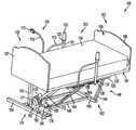
- Headboard 107 and footboard 108may be bolted to headboard and footboard support 217 , 218 , respectively so that they are removable for ease of shipping.
- Headboard 107may be constructed from a sheet of plywood or any other suitable material.
- Headboard 107may be finished with laminate surfaces or paint.
- Footboard 108may be constructed from aluminum or any other suitable material.
- Footboard 108may include a non-slip surface 109 and otherwise may be finished with a laminate surface or paint.
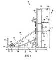
- a pivot lug 260is provided at upper end 245 of each leg member 144 , as shown in FIG. 2B .
- Each pivot lug 260may be a U-shaped bracket that includes two parallel walls 261 and a pair of pivot apertures 262 .
- each pivot aperture 262is located in a respective wall 261 and pivot apertures 262 may be aligned on a pivot axis R.
- a light source 1100serves as a reading light on headboard 107 .
- the reading lightmay include a light source on an adjustable stalk (not shown).
- the light sourcecan be turned on or off to provide light for a user.
- light source 1100is a laser light source which provides a stimulus for patients that suffer from Parkinson's Disease. It has been shown that if Parkinson's patients are provided with a stimulus to visually focus on, it may help to stimulate their motor functions.
- the laser light 1100may be configured so that when deck assembly 101 is in a prone position, the laser is projected onto the ceiling of the room.
- headboard 107would be located adjacent a wall when deck assembly 101 is in the prone position and the distance from a lateral edge of deck assembly 101 to vertical support 150 is such that it would be unlikely for a person to unwittingly place a body part between vertical support 150 and upper frame 104 .
- the only potential pinch pointis between balance member 156 and upper frame 104 .
- balance member 156is located along a longitudinal center line of base assembly 140 .
- the motion of deck assembly 101would prohibit a person from unwittingly placing a body part between deck assembly 101 and balance member 156 when deck assembly 101 is tilted to the upright position.
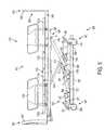
- Tilting actuator assembly 552may be a linear actuator that includes a motor 570 , a motor coupling 571 and a telescoping arm 572 .
- An actuator pivot lug 573may be coupled to telescoping arm 572 at an end opposite from motor coupling 571 .
- Tilting actuator assembly 552may be any commercially available linear actuator assembly, such as CC Linear Actuators from Nook Industries, Inc. of Cleveland, Ohio, capable of tilting deck assembly 501 , which may be substantially heavier than deck assembly 101 .
- an embodiment of deck assembly 101weighs approximately 185 lbs. and an embodiment of deck assembly 501 weighs approximately 500 lbs.
- the power supply boxmay also contain control logic for controlling the tilting, elevating and lowering of deck assembly 501 as well as for controlling the caster locks 581 .
- sensorsmay be provided on deck assembly 501 and/or on the output arms of cart actuator 589 and/or leg member actuator 592 . The signals from such sensors may be processed by the control logic to assure the safe operation of the bed.
- the control logicmay require that deck assembly 501 be in a fully lowered position prior to tilting.
- the control logicmay require that deck assembly 501 be in a prone position prior to elevating or lowering.
- the control logicmay require casters 580 to be locked before raising, lowering or tilting deck assembly 501 .
Landscapes
- Health & Medical Sciences (AREA)
- Nursing (AREA)
- Life Sciences & Earth Sciences (AREA)
- Animal Behavior & Ethology (AREA)
- General Health & Medical Sciences (AREA)
- Public Health (AREA)
- Veterinary Medicine (AREA)
- Invalid Beds And Related Equipment (AREA)
Abstract
Description
Claims (12)
Priority Applications (1)
| Application Number | Priority Date | Filing Date | Title |
|---|---|---|---|
| US11/417,052US7802331B2 (en) | 2005-05-04 | 2006-05-04 | Tilting furniture |
Applications Claiming Priority (2)
| Application Number | Priority Date | Filing Date | Title |
|---|---|---|---|
| US67733405P | 2005-05-04 | 2005-05-04 | |
| US11/417,052US7802331B2 (en) | 2005-05-04 | 2006-05-04 | Tilting furniture |
Publications (2)
| Publication Number | Publication Date |
|---|---|
| US20070000059A1 US20070000059A1 (en) | 2007-01-04 |
| US7802331B2true US7802331B2 (en) | 2010-09-28 |
Family
ID=37587822
Family Applications (1)
| Application Number | Title | Priority Date | Filing Date |
|---|---|---|---|
| US11/417,052Expired - Fee RelatedUS7802331B2 (en) | 2005-05-04 | 2006-05-04 | Tilting furniture |
Country Status (1)
| Country | Link |
|---|---|
| US (1) | US7802331B2 (en) |
Cited By (13)
| Publication number | Priority date | Publication date | Assignee | Title |
|---|---|---|---|---|
| US20130007960A1 (en)* | 2009-12-23 | 2013-01-10 | Nikou Manouchehri | Hospital chair beds with stowable stand-assist supports |
| US20140338129A1 (en)* | 2012-02-14 | 2014-11-20 | Magna Closures Inc. | Bed with user-assist mechanism |
| US9314385B2 (en) | 2011-04-11 | 2016-04-19 | Pratt & Whitney Canada Corp. | Piece of furniture, such as an adjustable bed, having an adjustable platform |
| US20160213541A1 (en)* | 2013-08-30 | 2016-07-28 | General Electric Company | Table driving system for patient table |
| CN104224469B (en)* | 2014-07-24 | 2017-01-11 | 温州医科大学附属第二医院育英儿童医院 | Rehabilitation standing bed |
| US20170246069A1 (en)* | 2014-03-07 | 2017-08-31 | Eugene Kalinowski | Motorized air walker and suspension system for paralyzed persons |
| US20180000675A1 (en)* | 2016-06-29 | 2018-01-04 | Stryker Corporation | Patient Support Systems With Rotary Actuators Having Cycloidal Drives |
| US9999558B2 (en) | 2011-04-11 | 2018-06-19 | Usine Rotec Inc. | Piece of furniture, such as an adjustable bed, having an adjustable platform |
| US20190183708A1 (en)* | 2016-08-26 | 2019-06-20 | ReActive Robotics GmbH | Device For Converting A Bed, In Particular A Care Bed, Sick Bed, Hospital Bed, Or Intensive-Care Bed, From A Horizontal Position Into An Inclined Position With Respect To The Logitudinal Sides Of The Bed |
| US10610429B2 (en) | 2016-06-29 | 2020-04-07 | Stryker Corporation | Rotary actuator having clutch assembly for use with patient support apparatus |
| US10765575B2 (en) | 2016-06-29 | 2020-09-08 | Stryker Corporation | Patient support systems with rotary actuators comprising rotation limiting devices |
| US10813807B2 (en) | 2016-06-29 | 2020-10-27 | Stryker Corporation | Patient support systems with hollow rotary actuators |
| US20200397147A1 (en)* | 2019-06-18 | 2020-12-24 | Nisco (Thailand) Co., Ltd | Adjustable bed with tilting mechanisms |
Families Citing this family (3)
| Publication number | Priority date | Publication date | Assignee | Title |
|---|---|---|---|---|
| US7788748B2 (en)* | 2005-04-06 | 2010-09-07 | Piedmont Global Solutions, Inc. | Hospital beds with a rotating sleep surface that can translate into a chair configuration |
| US9648961B1 (en)* | 2015-02-16 | 2017-05-16 | Angela Laverne Lovely | Translocatable child care changing station |
| US11957248B2 (en)* | 2022-04-05 | 2024-04-16 | L&P Property Management Company | Adjustable bed base with subframe for lift and tilt |
Citations (95)
| Publication number | Priority date | Publication date | Assignee | Title |
|---|---|---|---|---|
| US1894739A (en)* | 1929-10-26 | 1933-01-17 | Levi L Gilbert | Surgical operating support |
| US2571829A (en)* | 1947-01-13 | 1951-10-16 | Thomas C Buckley | Chiropractic adjustment table |
| US2764763A (en)* | 1954-07-02 | 1956-10-02 | Silver Sam | Patient-operated hospital bed |
| US2828172A (en)* | 1956-12-26 | 1958-03-25 | Ritter Co Inc | Medical examination, operating, and x-ray table |
| US2887691A (en)* | 1957-06-26 | 1959-05-26 | Lawrence J Talarico | Hospital bed |
| US3036314A (en) | 1957-06-27 | 1962-05-29 | Justin J Wetzler | Adjustable bed |
| US3089692A (en)* | 1961-04-03 | 1963-05-14 | Blomqvist Olle | Medical tipping tables |
| US3293667A (en)* | 1965-10-20 | 1966-12-27 | John F Ohrberg | Adjustable, ambulating, tilting and reclining bed |
| US3373453A (en) | 1966-09-13 | 1968-03-19 | Goodman Robert | Vertically adjustable bed |
| US3503082A (en) | 1968-12-18 | 1970-03-31 | Malcolm Kerwit | Hospital bed |
| US3609777A (en) | 1968-08-29 | 1971-10-05 | Nat Res Dev | Beds |
| US3611452A (en) | 1970-06-25 | 1971-10-12 | American Hospital Supply Corp | Invalid bed construction |
| US3640520A (en)* | 1969-06-11 | 1972-02-08 | Tri W G Inc | Therapy treatment tilt table |
| US3806109A (en) | 1972-08-14 | 1974-04-23 | Tri W G Inc | Tiltable treatment table |
| US3964786A (en)* | 1974-12-20 | 1976-06-22 | David Mashuda | Mechanized wheelchair |
| US3997926A (en) | 1975-07-09 | 1976-12-21 | England Robert W | Bed with automatic tilting occupant support |
| US4021028A (en)* | 1976-03-29 | 1977-05-03 | Tri W-G, Inc. | Tiltable treatment table |
| US4059255A (en)* | 1977-06-09 | 1977-11-22 | Adjusting Tables Inc. | Adjustable table for physical therapy |
| US4274167A (en) | 1979-08-31 | 1981-06-23 | Immel Joseph D | Oscillating bed |
| US4535492A (en) | 1982-12-16 | 1985-08-20 | Spectro Industries, Inc. | Pillow bed mechanism |
| US4556198A (en) | 1983-12-19 | 1985-12-03 | Fuji Electric Co., Ltd. | Height adjusting lifter for hospital bed |
| US4613997A (en)* | 1984-06-14 | 1986-09-30 | Langdale Oscar E | Vertical access convalescent bed |
| US4780919A (en)* | 1987-10-20 | 1988-11-01 | Harrison Mildred B | Hospital bed |
| US4987622A (en) | 1989-05-22 | 1991-01-29 | Shockey Winfred S | Self-operated stand up support apparatus |
| US5014688A (en)* | 1990-09-06 | 1991-05-14 | Tri W-G, Inc. | Patient treatment table |
| US5072463A (en)* | 1991-04-11 | 1991-12-17 | Willis William J | EZ access bed |
| US5074000A (en) | 1991-01-11 | 1991-12-24 | Ssi Medical Services, Inc. | Apparatus for performing head and foot Trendelenburg therapy |
| US5103512A (en) | 1985-05-07 | 1992-04-14 | Nova Technologies, Inc. | Patient transfer arrangement |
| US5136742A (en) | 1989-10-06 | 1992-08-11 | Dick Stebbins | Nursing home bed tilt apparatus |
| US5205004A (en) | 1990-11-28 | 1993-04-27 | J. Nesbit Evans & Co. Ltd. | Vertically adjustable and tiltable bed frame |
| US5230113A (en) | 1992-04-14 | 1993-07-27 | Good Turn, Inc. | Multiple position adjustable day night patient bed chair |
| US5230112A (en) | 1990-11-21 | 1993-07-27 | Diasonics, Inc. | Patient support table |
| US5275175A (en) | 1992-08-18 | 1994-01-04 | Sylvain Poirier | Postural drainage table |
| US5299334A (en) | 1992-01-21 | 1994-04-05 | Kinetic Concepts, Inc. | Hydraulic oscillating treatment table and method |
| US5308359A (en)* | 1991-06-24 | 1994-05-03 | Lossing Orthopedic, Inc. | Apparatus and method for producing spinal distraction |
| US5317769A (en) | 1992-11-10 | 1994-06-07 | Hill-Rom Company, Inc. | Hospital bed |
| US5345632A (en) | 1991-04-18 | 1994-09-13 | General Electric Cgr S.A. | Underframe for medical examination table |
| US5346280A (en) | 1992-03-31 | 1994-09-13 | Deumite Norman A | Chair with automatic standing aid |
| US5361436A (en) | 1992-09-02 | 1994-11-08 | Siemens Aktiengesellschaft | Patient support apparatus for medical examinations |
| US5361433A (en) | 1993-05-21 | 1994-11-08 | Vanzant B W | Pneumatic sit/stand assistance device utilizing sequential inflation for stabilizing effects |
| US5404604A (en) | 1991-06-14 | 1995-04-11 | Koninklijke Auping B.V. | Adjusting device for a bed or chair |
| US5416939A (en) | 1994-01-21 | 1995-05-23 | Maalouli; Raja G. | Tilting bed apparatus |
| US5454126A (en)* | 1994-01-25 | 1995-10-03 | Hill-Rom Company, Inc. | Foot egress chair bed |
| US5513867A (en) | 1993-08-24 | 1996-05-07 | University Of Utah | Seat-lift wheelchair |
| US5586349A (en) | 1994-03-04 | 1996-12-24 | Smiths Industries Public Limited Company | Trolleys |
| US5621933A (en) | 1993-12-08 | 1997-04-22 | Knapp; Juergen | Lift column for a surgical support |
| US5720059A (en) | 1995-09-13 | 1998-02-24 | M.C. Healthcare Products Inc. | Tilting mechanism for bed |
| US5774915A (en) | 1995-09-13 | 1998-07-07 | Standex International | Patient treatment apparatus |
| US5778467A (en)* | 1995-09-13 | 1998-07-14 | Standex International | Patient treatment apparatus |
| US5782870A (en) | 1995-08-10 | 1998-07-21 | Lloyd Table Company | Foot plate control mechanism for chiropractic table |
| US5790997A (en)* | 1995-08-04 | 1998-08-11 | Hill-Rom Inc. | Table/chair egress device |
| US5790996A (en) | 1996-09-27 | 1998-08-11 | Siemens-Elma Ab | Examination table for supporting and positioning a patient in a medical examination apparatus |
| US5864901A (en) | 1996-04-18 | 1999-02-02 | Bavaria Patente Und Lizenzen Verwer-Tungsgesellschaft Mbh | Apparatus for supporting an individual in selectively adjustable orientations |
| US5916085A (en) | 1996-11-12 | 1999-06-29 | Wells; John R. | Rotator for assisting a person in lying down on and getting up from a bed and method of use |
| US5935061A (en)* | 1997-01-03 | 1999-08-10 | Biosense, Inc. | Obstetrical instrument system and method |
| US6058533A (en)* | 1998-09-17 | 2000-05-09 | Larry A. Nelson | Bed apparatus |
| US6070281A (en) | 1997-04-18 | 2000-06-06 | Siemens Aktiengesellschaft | Patient orientation table |
| US6119287A (en) | 1998-05-29 | 2000-09-19 | Phillips; Barry S. | Lift and transfer apparatus for a disabled person |
| US6163903A (en) | 1994-01-25 | 2000-12-26 | Hill-Rom Inc. | Chair bed |
| US6173461B1 (en)* | 1996-09-12 | 2001-01-16 | Michael Alexander | Support unit |
| US6209463B1 (en) | 1999-03-12 | 2001-04-03 | United Metal Fabricators, Inc. | Medical examination table |
| US6243897B1 (en) | 1997-07-22 | 2001-06-12 | Kozo Sumiya | Therapeutic bed for inversely suspending/standing human body |
| US6353949B1 (en) | 2000-02-04 | 2002-03-12 | Michael G. Falbo | Tilt table for disease diagnosis |
| US20020066142A1 (en)* | 1999-12-29 | 2002-06-06 | Osborne Eugene E. | Hospital bed |
| US20020148044A1 (en) | 2000-04-04 | 2002-10-17 | Stephen Hayes | Patient support |
| US6473922B1 (en) | 1999-09-15 | 2002-11-05 | Sunrise Medical Hhg Inc. | Kinematic motion of articulated bed |
| US6481688B1 (en)* | 1992-11-30 | 2002-11-19 | Hill-Rom Services, Inc. | Hospital bed communication and control device |
| US6484332B2 (en) | 1999-12-08 | 2002-11-26 | Med-Tec Iowa, Inc. | System for vertical to horizontal movement and lateral movement of a patient |
| US6557940B2 (en) | 1999-12-22 | 2003-05-06 | Matsushita Electric Works, Ltd. | Chair assisting rising movements |
| US20030086749A1 (en)* | 2001-11-08 | 2003-05-08 | Oliver Dana Andrew | Surgical arm assembly including quick connect mechanism |
| US20030101513A1 (en)* | 2001-03-29 | 2003-06-05 | William Beaumont Hospital | X-ray transparent hospital bed compatible with open geometry portable CT scanners |
| US6615430B2 (en) | 2000-02-18 | 2003-09-09 | Hill-Rom Services, Inc. | Imaging stretcher |
| US6637055B1 (en)* | 2002-05-23 | 2003-10-28 | Dharamraj Nanan | Yoga inversion bed with leg attachment |
| US6681423B2 (en) | 2000-03-29 | 2004-01-27 | Stille Surgical Ab | Surgical table with displacement arrangement |
| US6694548B2 (en)* | 1994-01-25 | 2004-02-24 | Hill-Rom Services, Inc. | Hospital bed |
| US6721976B2 (en) | 2002-02-05 | 2004-04-20 | Reliance Medical Products, Inc. | Surgical table |
| US6739004B1 (en) | 1999-09-02 | 2004-05-25 | Linak A/S | Rotary actuator, especially for adjustable furniture, including beds and bottom for beds |
| US20040128766A1 (en) | 2002-10-25 | 2004-07-08 | Brian Freeborn | Adjustable bed carriage |
| US6846042B2 (en) | 1997-02-10 | 2005-01-25 | Hill-Rom Services, Inc. | Ambulatory care chair |
| US6862762B1 (en) | 2002-01-11 | 2005-03-08 | Wlf, L.L.C. | Patient support apparatus |
| US6868567B2 (en) | 2002-07-19 | 2005-03-22 | Gf Health Products, Inc. | Height and angle adjustable bed |
| US6912746B2 (en) | 2001-11-17 | 2005-07-05 | Medi-Plinth Limited | Bed |
| US6954951B2 (en) | 2003-12-12 | 2005-10-18 | Leonard Lieboff | Spica cast gurney |
| US6957456B2 (en) | 2004-02-11 | 2005-10-25 | Jaron, Llc | Bed lift |
| US6971131B2 (en) | 2001-01-13 | 2005-12-06 | Eschmann Holdings Limited | Surgical tables |
| US6978501B2 (en) | 1995-01-31 | 2005-12-27 | Kci Licensing, Inc. | Bariatric bed apparatus and methods |
| US6986179B2 (en) | 2002-11-26 | 2006-01-17 | Ge Medical Systems Global Technology Company, Llc | Grouted tilting patient positioning table for vascular applications |
| US7000271B2 (en) | 2002-11-12 | 2006-02-21 | Ge Medical Systems Global Technology Company, Llc | Table control method and table system |
| US7073222B1 (en) | 2003-05-06 | 2006-07-11 | Skripps Thomas K | Medical procedure table |
| US7097189B2 (en) | 2003-11-18 | 2006-08-29 | Lloyd Linden, Inc. | Wheelchair with self-raising seat |
| US7125167B2 (en) | 2003-03-04 | 2006-10-24 | Ge Medical Systems Global Technology Company, Llc | Method and apparatus for tilting in a patient positioning system |
| US7181793B2 (en) | 2002-10-28 | 2007-02-27 | Seung Jae Lee | Bed to adjust the slope of the bed according to brain waves and a method thereby |
| US7255397B2 (en) | 2004-08-25 | 2007-08-14 | Golden Technologies, Inc. | Infrared sensing lift chair |
| US7373677B2 (en) | 2002-10-25 | 2008-05-20 | Hans-Peter Barthelt | Rotary bed comprising an improved rotary hinge |
| US7472441B1 (en) | 2005-07-21 | 2009-01-06 | Lloyd Table Company | Automatic tilt-elevating chiropractic table |
- 2006
- 2006-05-04USUS11/417,052patent/US7802331B2/ennot_activeExpired - Fee Related
Patent Citations (100)
| Publication number | Priority date | Publication date | Assignee | Title |
|---|---|---|---|---|
| US1894739A (en)* | 1929-10-26 | 1933-01-17 | Levi L Gilbert | Surgical operating support |
| US2571829A (en)* | 1947-01-13 | 1951-10-16 | Thomas C Buckley | Chiropractic adjustment table |
| US2764763A (en)* | 1954-07-02 | 1956-10-02 | Silver Sam | Patient-operated hospital bed |
| US2828172A (en)* | 1956-12-26 | 1958-03-25 | Ritter Co Inc | Medical examination, operating, and x-ray table |
| US2887691A (en)* | 1957-06-26 | 1959-05-26 | Lawrence J Talarico | Hospital bed |
| US3036314A (en) | 1957-06-27 | 1962-05-29 | Justin J Wetzler | Adjustable bed |
| US3089692A (en)* | 1961-04-03 | 1963-05-14 | Blomqvist Olle | Medical tipping tables |
| US3293667A (en)* | 1965-10-20 | 1966-12-27 | John F Ohrberg | Adjustable, ambulating, tilting and reclining bed |
| US3373453A (en) | 1966-09-13 | 1968-03-19 | Goodman Robert | Vertically adjustable bed |
| US3609777A (en) | 1968-08-29 | 1971-10-05 | Nat Res Dev | Beds |
| US3503082A (en) | 1968-12-18 | 1970-03-31 | Malcolm Kerwit | Hospital bed |
| US3640520A (en)* | 1969-06-11 | 1972-02-08 | Tri W G Inc | Therapy treatment tilt table |
| US3611452A (en) | 1970-06-25 | 1971-10-12 | American Hospital Supply Corp | Invalid bed construction |
| US3806109A (en) | 1972-08-14 | 1974-04-23 | Tri W G Inc | Tiltable treatment table |
| US3964786A (en)* | 1974-12-20 | 1976-06-22 | David Mashuda | Mechanized wheelchair |
| US3997926A (en) | 1975-07-09 | 1976-12-21 | England Robert W | Bed with automatic tilting occupant support |
| US4021028A (en)* | 1976-03-29 | 1977-05-03 | Tri W-G, Inc. | Tiltable treatment table |
| US4059255A (en)* | 1977-06-09 | 1977-11-22 | Adjusting Tables Inc. | Adjustable table for physical therapy |
| US4274167A (en) | 1979-08-31 | 1981-06-23 | Immel Joseph D | Oscillating bed |
| US4535492A (en) | 1982-12-16 | 1985-08-20 | Spectro Industries, Inc. | Pillow bed mechanism |
| US4556198A (en) | 1983-12-19 | 1985-12-03 | Fuji Electric Co., Ltd. | Height adjusting lifter for hospital bed |
| US4613997A (en)* | 1984-06-14 | 1986-09-30 | Langdale Oscar E | Vertical access convalescent bed |
| US5103512A (en) | 1985-05-07 | 1992-04-14 | Nova Technologies, Inc. | Patient transfer arrangement |
| US4780919A (en)* | 1987-10-20 | 1988-11-01 | Harrison Mildred B | Hospital bed |
| US4987622A (en) | 1989-05-22 | 1991-01-29 | Shockey Winfred S | Self-operated stand up support apparatus |
| US5136742A (en) | 1989-10-06 | 1992-08-11 | Dick Stebbins | Nursing home bed tilt apparatus |
| US6725474B2 (en)* | 1990-05-16 | 2004-04-27 | Hill-Rom Services, Inc. | Hospital bed |
| US5014688A (en)* | 1990-09-06 | 1991-05-14 | Tri W-G, Inc. | Patient treatment table |
| US5230112A (en) | 1990-11-21 | 1993-07-27 | Diasonics, Inc. | Patient support table |
| US5205004A (en) | 1990-11-28 | 1993-04-27 | J. Nesbit Evans & Co. Ltd. | Vertically adjustable and tiltable bed frame |
| US5074000A (en) | 1991-01-11 | 1991-12-24 | Ssi Medical Services, Inc. | Apparatus for performing head and foot Trendelenburg therapy |
| US5072463A (en)* | 1991-04-11 | 1991-12-17 | Willis William J | EZ access bed |
| US5345632A (en) | 1991-04-18 | 1994-09-13 | General Electric Cgr S.A. | Underframe for medical examination table |
| US5404604A (en) | 1991-06-14 | 1995-04-11 | Koninklijke Auping B.V. | Adjusting device for a bed or chair |
| US5308359A (en)* | 1991-06-24 | 1994-05-03 | Lossing Orthopedic, Inc. | Apparatus and method for producing spinal distraction |
| US5299334A (en) | 1992-01-21 | 1994-04-05 | Kinetic Concepts, Inc. | Hydraulic oscillating treatment table and method |
| US5346280A (en) | 1992-03-31 | 1994-09-13 | Deumite Norman A | Chair with automatic standing aid |
| US5230113A (en) | 1992-04-14 | 1993-07-27 | Good Turn, Inc. | Multiple position adjustable day night patient bed chair |
| US5275175A (en) | 1992-08-18 | 1994-01-04 | Sylvain Poirier | Postural drainage table |
| US5361436A (en) | 1992-09-02 | 1994-11-08 | Siemens Aktiengesellschaft | Patient support apparatus for medical examinations |
| US5317769A (en) | 1992-11-10 | 1994-06-07 | Hill-Rom Company, Inc. | Hospital bed |
| US6481688B1 (en)* | 1992-11-30 | 2002-11-19 | Hill-Rom Services, Inc. | Hospital bed communication and control device |
| US5361433A (en) | 1993-05-21 | 1994-11-08 | Vanzant B W | Pneumatic sit/stand assistance device utilizing sequential inflation for stabilizing effects |
| US5513867A (en) | 1993-08-24 | 1996-05-07 | University Of Utah | Seat-lift wheelchair |
| US5621933A (en) | 1993-12-08 | 1997-04-22 | Knapp; Juergen | Lift column for a surgical support |
| US5416939A (en) | 1994-01-21 | 1995-05-23 | Maalouli; Raja G. | Tilting bed apparatus |
| US6163903A (en) | 1994-01-25 | 2000-12-26 | Hill-Rom Inc. | Chair bed |
| US6694548B2 (en)* | 1994-01-25 | 2004-02-24 | Hill-Rom Services, Inc. | Hospital bed |
| US5454126A (en)* | 1994-01-25 | 1995-10-03 | Hill-Rom Company, Inc. | Foot egress chair bed |
| US6336235B1 (en)* | 1994-01-25 | 2002-01-08 | Hill-Rom Services, Inc. | Chair bed |
| US5586349A (en) | 1994-03-04 | 1996-12-24 | Smiths Industries Public Limited Company | Trolleys |
| US6978501B2 (en) | 1995-01-31 | 2005-12-27 | Kci Licensing, Inc. | Bariatric bed apparatus and methods |
| US5790997A (en)* | 1995-08-04 | 1998-08-11 | Hill-Rom Inc. | Table/chair egress device |
| US5782870A (en) | 1995-08-10 | 1998-07-21 | Lloyd Table Company | Foot plate control mechanism for chiropractic table |
| US5784734A (en)* | 1995-09-13 | 1998-07-28 | Standex International | Patient treatment apparatus |
| US5720059A (en) | 1995-09-13 | 1998-02-24 | M.C. Healthcare Products Inc. | Tilting mechanism for bed |
| US5774915A (en) | 1995-09-13 | 1998-07-07 | Standex International | Patient treatment apparatus |
| US5778467A (en)* | 1995-09-13 | 1998-07-14 | Standex International | Patient treatment apparatus |
| US5794286A (en)* | 1995-09-13 | 1998-08-18 | Standex International | Patient treatment apparatus |
| US5864901A (en) | 1996-04-18 | 1999-02-02 | Bavaria Patente Und Lizenzen Verwer-Tungsgesellschaft Mbh | Apparatus for supporting an individual in selectively adjustable orientations |
| US6173461B1 (en)* | 1996-09-12 | 2001-01-16 | Michael Alexander | Support unit |
| US5790996A (en) | 1996-09-27 | 1998-08-11 | Siemens-Elma Ab | Examination table for supporting and positioning a patient in a medical examination apparatus |
| US5916085A (en) | 1996-11-12 | 1999-06-29 | Wells; John R. | Rotator for assisting a person in lying down on and getting up from a bed and method of use |
| US5935061A (en)* | 1997-01-03 | 1999-08-10 | Biosense, Inc. | Obstetrical instrument system and method |
| US6846042B2 (en) | 1997-02-10 | 2005-01-25 | Hill-Rom Services, Inc. | Ambulatory care chair |
| US6070281A (en) | 1997-04-18 | 2000-06-06 | Siemens Aktiengesellschaft | Patient orientation table |
| US6243897B1 (en) | 1997-07-22 | 2001-06-12 | Kozo Sumiya | Therapeutic bed for inversely suspending/standing human body |
| US6119287A (en) | 1998-05-29 | 2000-09-19 | Phillips; Barry S. | Lift and transfer apparatus for a disabled person |
| US6058533A (en)* | 1998-09-17 | 2000-05-09 | Larry A. Nelson | Bed apparatus |
| US6209463B1 (en) | 1999-03-12 | 2001-04-03 | United Metal Fabricators, Inc. | Medical examination table |
| US6739004B1 (en) | 1999-09-02 | 2004-05-25 | Linak A/S | Rotary actuator, especially for adjustable furniture, including beds and bottom for beds |
| US6473922B1 (en) | 1999-09-15 | 2002-11-05 | Sunrise Medical Hhg Inc. | Kinematic motion of articulated bed |
| US6484332B2 (en) | 1999-12-08 | 2002-11-26 | Med-Tec Iowa, Inc. | System for vertical to horizontal movement and lateral movement of a patient |
| US6557940B2 (en) | 1999-12-22 | 2003-05-06 | Matsushita Electric Works, Ltd. | Chair assisting rising movements |
| US20020066142A1 (en)* | 1999-12-29 | 2002-06-06 | Osborne Eugene E. | Hospital bed |
| US6957461B2 (en) | 1999-12-29 | 2005-10-25 | Hill-Rom Services, Inc. | Hospital bed |
| US6353949B1 (en) | 2000-02-04 | 2002-03-12 | Michael G. Falbo | Tilt table for disease diagnosis |
| US6615430B2 (en) | 2000-02-18 | 2003-09-09 | Hill-Rom Services, Inc. | Imaging stretcher |
| US6681423B2 (en) | 2000-03-29 | 2004-01-27 | Stille Surgical Ab | Surgical table with displacement arrangement |
| US20020148044A1 (en) | 2000-04-04 | 2002-10-17 | Stephen Hayes | Patient support |
| US6971131B2 (en) | 2001-01-13 | 2005-12-06 | Eschmann Holdings Limited | Surgical tables |
| US20030101513A1 (en)* | 2001-03-29 | 2003-06-05 | William Beaumont Hospital | X-ray transparent hospital bed compatible with open geometry portable CT scanners |
| US20030086749A1 (en)* | 2001-11-08 | 2003-05-08 | Oliver Dana Andrew | Surgical arm assembly including quick connect mechanism |
| US6912746B2 (en) | 2001-11-17 | 2005-07-05 | Medi-Plinth Limited | Bed |
| US6862762B1 (en) | 2002-01-11 | 2005-03-08 | Wlf, L.L.C. | Patient support apparatus |
| US6721976B2 (en) | 2002-02-05 | 2004-04-20 | Reliance Medical Products, Inc. | Surgical table |
| US6637055B1 (en)* | 2002-05-23 | 2003-10-28 | Dharamraj Nanan | Yoga inversion bed with leg attachment |
| US6868567B2 (en) | 2002-07-19 | 2005-03-22 | Gf Health Products, Inc. | Height and angle adjustable bed |
| US20040128766A1 (en) | 2002-10-25 | 2004-07-08 | Brian Freeborn | Adjustable bed carriage |
| US7373677B2 (en) | 2002-10-25 | 2008-05-20 | Hans-Peter Barthelt | Rotary bed comprising an improved rotary hinge |
| US7181793B2 (en) | 2002-10-28 | 2007-02-27 | Seung Jae Lee | Bed to adjust the slope of the bed according to brain waves and a method thereby |
| US7000271B2 (en) | 2002-11-12 | 2006-02-21 | Ge Medical Systems Global Technology Company, Llc | Table control method and table system |
| US6986179B2 (en) | 2002-11-26 | 2006-01-17 | Ge Medical Systems Global Technology Company, Llc | Grouted tilting patient positioning table for vascular applications |
| US7125167B2 (en) | 2003-03-04 | 2006-10-24 | Ge Medical Systems Global Technology Company, Llc | Method and apparatus for tilting in a patient positioning system |
| US7073222B1 (en) | 2003-05-06 | 2006-07-11 | Skripps Thomas K | Medical procedure table |
| US7097189B2 (en) | 2003-11-18 | 2006-08-29 | Lloyd Linden, Inc. | Wheelchair with self-raising seat |
| US6954951B2 (en) | 2003-12-12 | 2005-10-18 | Leonard Lieboff | Spica cast gurney |
| US6957456B2 (en) | 2004-02-11 | 2005-10-25 | Jaron, Llc | Bed lift |
| US7255397B2 (en) | 2004-08-25 | 2007-08-14 | Golden Technologies, Inc. | Infrared sensing lift chair |
| US7472441B1 (en) | 2005-07-21 | 2009-01-06 | Lloyd Table Company | Automatic tilt-elevating chiropractic table |
Non-Patent Citations (4)
| Title |
|---|
| Brochure for Tilt Table-Model 600T, on sale more than one year prior to May 4, 2005. |
| Brochure for Tilt Table—Model 600T, on sale more than one year prior to May 4, 2005. |
| Brochure for Tilt Table-Model TT-700, on sale more than one year prior to May 4, 2005. |
| Brochure for Tilt Table—Model TT-700, on sale more than one year prior to May 4, 2005. |
Cited By (19)
| Publication number | Priority date | Publication date | Assignee | Title |
|---|---|---|---|---|
| US9265677B2 (en)* | 2009-12-23 | 2016-02-23 | Piedmont 361, Llc | Hospital chair beds with stowable stand-assist supports |
| US20130007960A1 (en)* | 2009-12-23 | 2013-01-10 | Nikou Manouchehri | Hospital chair beds with stowable stand-assist supports |
| US9314385B2 (en) | 2011-04-11 | 2016-04-19 | Pratt & Whitney Canada Corp. | Piece of furniture, such as an adjustable bed, having an adjustable platform |
| US9757292B2 (en) | 2011-04-11 | 2017-09-12 | Usine Rotec Inc. | Piece of furniture, such as an adjustable bed, having an adjustable platform |
| US9999558B2 (en) | 2011-04-11 | 2018-06-19 | Usine Rotec Inc. | Piece of furniture, such as an adjustable bed, having an adjustable platform |
| US20140338129A1 (en)* | 2012-02-14 | 2014-11-20 | Magna Closures Inc. | Bed with user-assist mechanism |
| US20160213541A1 (en)* | 2013-08-30 | 2016-07-28 | General Electric Company | Table driving system for patient table |
| US10299981B2 (en)* | 2014-03-07 | 2019-05-28 | Eugene Kalinowski | Motorized air walker and suspension system for paralyzed persons |
| US20170246069A1 (en)* | 2014-03-07 | 2017-08-31 | Eugene Kalinowski | Motorized air walker and suspension system for paralyzed persons |
| CN104224469B (en)* | 2014-07-24 | 2017-01-11 | 温州医科大学附属第二医院育英儿童医院 | Rehabilitation standing bed |
| US20180000675A1 (en)* | 2016-06-29 | 2018-01-04 | Stryker Corporation | Patient Support Systems With Rotary Actuators Having Cycloidal Drives |
| US10610429B2 (en) | 2016-06-29 | 2020-04-07 | Stryker Corporation | Rotary actuator having clutch assembly for use with patient support apparatus |
| US10765575B2 (en) | 2016-06-29 | 2020-09-08 | Stryker Corporation | Patient support systems with rotary actuators comprising rotation limiting devices |
| US10813807B2 (en) | 2016-06-29 | 2020-10-27 | Stryker Corporation | Patient support systems with hollow rotary actuators |
| US10864128B2 (en)* | 2016-06-29 | 2020-12-15 | Stryker Corporation | Patient support systems with rotary actuators having cycloidal drives |
| US20190183708A1 (en)* | 2016-08-26 | 2019-06-20 | ReActive Robotics GmbH | Device For Converting A Bed, In Particular A Care Bed, Sick Bed, Hospital Bed, Or Intensive-Care Bed, From A Horizontal Position Into An Inclined Position With Respect To The Logitudinal Sides Of The Bed |
| US11213446B2 (en)* | 2016-08-26 | 2022-01-04 | ReActive Robotics GmbH | Device for converting a bed, in particular a care bed, sick bed, hospital bed, or intensive-care bed, from a horizontal position into an inclined position with respect to the logitudinal sides of the bed |
| US20200397147A1 (en)* | 2019-06-18 | 2020-12-24 | Nisco (Thailand) Co., Ltd | Adjustable bed with tilting mechanisms |
| US11766132B2 (en)* | 2019-06-18 | 2023-09-26 | Nisco (Thailand) Co., Ltd | Adjustable bed with tilting mechanisms |
Also Published As
| Publication number | Publication date |
|---|---|
| US20070000059A1 (en) | 2007-01-04 |
Similar Documents
| Publication | Publication Date | Title |
|---|---|---|
| US7802331B2 (en) | Tilting furniture | |
| US7774876B2 (en) | Tilting bed | |
| JP6899171B2 (en) | Versatile, versatile and reassembleable reclining chair combined bed | |
| US10307316B2 (en) | Mobility device for physically disabled people | |
| US7568240B2 (en) | Patient transfer system | |
| US6779210B1 (en) | Elevating bed | |
| US6540250B1 (en) | Height adjustable wheelchair | |
| US7698761B2 (en) | Adjustable bed having four linear actuators | |
| US7428760B2 (en) | Lifting mechanism and health care equipment that incorporates the lifting mechanism | |
| US9173797B2 (en) | Siderail assembly for patient support apparatus | |
| US20030093863A1 (en) | Bed | |
| US7506385B2 (en) | Submersing bathing and transfer chair | |
| US12005013B2 (en) | Patient support apparatus with articulating fowler deck section traveling through arcuate path | |
| US5853015A (en) | Lightweight easily transportable personal lifting devices | |
| US20050081294A1 (en) | Universal power table | |
| US20130212807A1 (en) | Bed chair | |
| US10363187B2 (en) | Methods and apparatus for moving a patient from a reclining position to an upright sitting position | |
| WO2006103457A1 (en) | Height-adjustable bedframes | |
| US20070145723A1 (en) | Vertically adjustable folding wheelchair | |
| US12036159B2 (en) | Patient support apparatus having removable litter and base with foot deck section | |
| US9421138B1 (en) | Self-propelling standing commode wheelchair | |
| US5046571A (en) | Vertically adjustable wheel chair | |
| JP5142693B2 (en) | Transfer assist device | |
| AU2002301101B2 (en) | Elevating Bed | |
| WO2005097035A1 (en) | Adjustable bed |
Legal Events
| Date | Code | Title | Description |
|---|---|---|---|
| AS | Assignment | Owner name:STAND-UP BED COMPANY, TEXAS Free format text:ASSIGNMENT OF ASSIGNORS INTEREST;ASSIGNORS:BROWN, BOBBY;HOLLOWAY, RANDY;HICKS, DONNY;AND OTHERS;REEL/FRAME:021195/0558 Effective date:20060726 | |
| AS | Assignment | Owner name:TRANSITIONS INDUSTRIES, INC., TEXAS Free format text:CHANGE OF NAME;ASSIGNOR:THE STANDUP BED COMPANY;REEL/FRAME:021200/0211 Effective date:20071231 | |
| STCF | Information on status: patent grant | Free format text:PATENTED CASE | |
| AS | Assignment | Owner name:JPMORGAN CHASE BANK, NA, KENTUCKY Free format text:SECURITY AGREEMENT;ASSIGNOR:TRANSITIONS INDUSTRIES, LLC;REEL/FRAME:026273/0785 Effective date:20100617 | |
| REMI | Maintenance fee reminder mailed | ||
| FPAY | Fee payment | Year of fee payment:4 | |
| SULP | Surcharge for late payment | ||
| MAFP | Maintenance fee payment | Free format text:PAYMENT OF MAINTENANCE FEE, 8TH YR, SMALL ENTITY (ORIGINAL EVENT CODE: M2552) Year of fee payment:8 | |
| FEPP | Fee payment procedure | Free format text:MAINTENANCE FEE REMINDER MAILED (ORIGINAL EVENT CODE: REM.); ENTITY STATUS OF PATENT OWNER: SMALL ENTITY | |
| LAPS | Lapse for failure to pay maintenance fees | Free format text:PATENT EXPIRED FOR FAILURE TO PAY MAINTENANCE FEES (ORIGINAL EVENT CODE: EXP.); ENTITY STATUS OF PATENT OWNER: SMALL ENTITY | |
| STCH | Information on status: patent discontinuation | Free format text:PATENT EXPIRED DUE TO NONPAYMENT OF MAINTENANCE FEES UNDER 37 CFR 1.362 | |
| FP | Lapsed due to failure to pay maintenance fee | Effective date:20220928 |