US7802121B1 - Auxiliary power system - Google Patents
Auxiliary power systemDownload PDFInfo
- Publication number
- US7802121B1 US7802121B1US11/390,355US39035506AUS7802121B1US 7802121 B1US7802121 B1US 7802121B1US 39035506 AUS39035506 AUS 39035506AUS 7802121 B1US7802121 B1US 7802121B1
- Authority
- US
- United States
- Prior art keywords
- power
- power supply
- capacitor
- controller
- boost converter
- Prior art date
- Legal status (The legal status is an assumption and is not a legal conclusion. Google has not performed a legal analysis and makes no representation as to the accuracy of the status listed.)
- Expired - Fee Related, expires
Links
Images


Classifications
- G—PHYSICS
- G06—COMPUTING OR CALCULATING; COUNTING
- G06F—ELECTRIC DIGITAL DATA PROCESSING
- G06F1/00—Details not covered by groups G06F3/00 - G06F13/00 and G06F21/00
- G06F1/26—Power supply means, e.g. regulation thereof
- G06F1/263—Arrangements for using multiple switchable power supplies, e.g. battery and AC
Definitions
- the present inventiongenerally relates to the field of power supplies, and more particularly to a method and system for providing auxiliary power during a power interruption.
- a financial institutionmay require an electrical energy supply to power computer systems and server systems which handle financial transactions. If a power interruption should occur, financial transactions may not be completed, may not be recordable and may not be accessible. When financial transactions are not completed, lost revenue and increased maintenance costs may be attributed to the financial institution.
- electrical equipmentmay include a power supply coupled to an alternating current (AC) power source.
- ACalternating current
- a conventional approach to prevent a power interruptionis to provide supplemental power to electrical equipment during a power interruption by an uninterruptible power supply (UPS) added to the power supply of the electrical equipment.
- UPS equipmentmay provide a continuous load of AC power to electrical equipment during the instance of an interruption or power drop of the AC power source.
- UPS equipmentwhich may include a battery, battery charger and inverter, may significantly increase the cost to produce the electrical equipment. Additionally, in order to supply a typical AC power supply of 120 Volts at 60 Hertz, a battery of the UPS equipment may be at least 12 volts in typical applications. Batteries of at least 12 volts tend to be large and heavy. As a result, addition of UPS equipment increases the form factor and weight of electrical equipment. Consequently, a method and system of providing auxiliary power during a power interruption is necessary.
- an auxiliary power system of the present inventionmay be added to a power supply to provide auxiliary power for a load during a power dip or power interruption to the power supply.
- the auxiliary power systemmay include a power storage device and a power storage charger which is powered by the power supply when power is supplied to the power supply.
- the power storage chargermay charge the power storage device.
- the auxiliary power systemmay also include a boost converter to increase the output voltage supplied by the power storage device suitable for a load receiving power from the power supply.
- the boost convertermay also ensure a constant output voltage is provided to the load during a power interruption.
- FIG. 1depicts an auxiliary power system in accordance with an embodiment of the present invention
- FIG. 2depicts an auxiliary power system including a capacitor in accordance with an embodiment of the present invention
- FIG. 3depicts a boost converter in accordance with an embodiment of the present invention.
- FIG. 4depicts a process for providing auxiliary power during a power failure in accordance with an embodiment of the present invention.
- auxiliary power system of the present inventionmay be incorporated with conventional power supplies to provide auxiliary power to a load during a power interruption. It is contemplated that a power interruption may include any occurrence whereby a desired output power is not provided to the load. A power interruption may include a dip in the power supplied to the power supply, a failure to provide any power to the power supply, or an operational failure of the power supply itself. Depending upon the components and power ranges employed, it is contemplated that the auxiliary power system may supply power for a multitude of lengths of power interruptions.
- auxiliary power systemmay provide power for short term power interruptions, such as power interruptions of less than three (3) seconds which per international statistical data would cover most short term power interruptions.
- the auxiliary power systemmay provide electrical power to a load at a reduced cost, weight and form factor compared to conventional uninterruptible power system (UPS) equipment and may be easily added to a power supply without affecting the operation of the power supply.
- UPSuninterruptible power system
- auxiliary power system 100in accordance with an embodiment of the present invention is shown.
- auxiliary power system 100may be incorporated with a power supply 110 to provide auxiliary power during a power interruption.
- power supply 110may receive an alternating current (AC) supply and convert the AC supply to a DC supply suitable for load 150 .
- Power supply 110may include a transformer, rectifier, filter and regulator to accept an AC input supply and provide a regulated DC output supply.
- the auxiliary power system 100may be operable with any type of power supply without departing from the scope and intent of the present invention.
- Auxiliary power system 100may include a power storage charger 120 , a power storage device 130 and a boost converter 140 .
- power supply 110may supply DC power to the power storage charger 120 to allow charging of the power storage device 130 .
- the output power of the power supplymay be utilized to provide power to the power storage charger 120 , which may be a battery charger, capacitance charger and the like.
- Power storage device 130may be a rechargeable battery, capacitor and the like. If the output voltage is greater than the voltage necessary for the power storage charger 120 , then the power storage charger 120 may include a buck converter comprising a transistor, diode and inductor to decrease the voltage supplied to the power storage charger 120 .
- Boost converter 140may be coupled to the power storage device 130 .
- Boost converter 140may increase the input voltage provided by the power storage device to a higher voltage which may be supplied to the load 150 .
- boost converter 140may receive a 3 volt input voltage and increase the input voltage to an output voltage of 5 volts suitable for load 150 .
- Boost converter 140may include a controller, such as a pulse width modulated controller, which may control the operation of the boost converter 140 to ensure a constant output supply is provided to load 150 during the entire period of the power interruption.
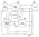
- Auxiliary power system 200may include a capacitor 210 , a capacitor charger 220 and a boost converter 230 .
- Power supply 240may receive power from an AC source 250 and may convert the AC supply to a regulated DC supply suitable for load 260 .
- AC source 250may refer to an AC utility outlet that may substantially provide a 120-240 Volt, 50-60 Hertz power supply. If there is an interruption or dip in the power received by the power supply 240 , a DC supply may be provided by capacitor 210 through the boost converter 230 .
- Controller 235may monitor the output voltage of the power supply and may control operation of the boost converter to maintain a constant output voltage while the voltage on capacitor 210 may be dropping as its power is transferred to the boost converter 230 .
- Boost converter 230may include an inductor 310 , a transistor 320 and a diode 330 .
- the output voltage of the boost convertermay be dependent upon the inductance value of inductor 310 .
- inductor currentflows through diode 330 to charge the output and increase the output voltage to a higher voltage than the input voltage supplied by capacitor 210 .
- the higher voltagemay be held constant through a feedback loop of the boost converter to hold a desired output voltage suitable for load 260 .
- Transistor 320may be a field effect transistor, bipolar junction transistor and the like and may operate as a switch within the boost converter 230 to facilitate operation of the boost converter.
- Capacitor charger 220may be coupled to the controller 235 whereby the power supply 240 may supply power to the capacitor charger 220 when the power supply is operational and is receiving input power from the AC source 250 .
- Capacitor charger 220may include a voltage provided by the power supply coupled with a series resistor. The voltage provided by the power supply coupled with the series resistor may be further coupled to capacitor 210 in series. The value of the resistor may be adjusted to provide a desired rate of charging, typically described as time constant RC.
- Auxiliary power system 200may include controller 235 which monitors the output voltage supplied by the power supply 240 . When a power disruption occurs, controller 235 may detect the power interruption. During a power interruption, controller 235 may initiate operation of the boost converter 230 and capacitor 210 may discharge its energy through boost converter 230 whereby a constant output voltage may be provided to load 260 . A diode on the output of the power supply prevents reverse current flow and allows the transfer of energy from the boost converter to the load.
- the output power supply provided by the auxiliary power system 200may be similar as provided by the power supply 240 when the power supply is receiving power from the AC power source 250 .
- controller 235may be a pulse width modulated controller.
- Controller 235may include a comparator which compares an output voltage of the power supply with a reference voltage to detect a power dip or power interruption. If the output voltage of the power supply is less than a reference voltage, then a power interruption may be detected by controller 235 . Further, controller 235 may control the duty cycle of the boost converter to provide a desired constant output power for load 260 .
- power supply 240may provide a 144 watt power supply to load 260 .
- Capacitor 210may be greater than 1 Farad.
- capacitor 210may be a 120 Farad capacitor that may be charged to 3 volts and may be discharged to 1 volt.
- boost converter 230may output an initial voltage of 12 volts and supply a current of 12 amperes creating 144 watts of power to load 260 , similar to the output power of the power supply 240 .
- auxiliary power system 200may provide auxiliary power for at least three seconds. This is advantageous as a large majority of power dips may only last less than 3 seconds. While auxiliary power system 200 may provide auxiliary power for at least three seconds, it is contemplated that a larger time period of auxiliary power may be provided by the auxiliary power system 200 of the present invention by employing a larger capacitance for capacitor 210 and the like.
- capacitor charge circuitry 220may include a buck converter which converts the output of the power supply of 12 volts to 3 volts suitable for charging capacitor 210 .
- a buck convertermay include a transistor, such as a field effect transistor, a diode, an inductor and a control circuit to assure a constant charge current to the capacitor 210 and to cut off the charge when capacitor 210 reaches the maximum specified voltage, such as 3 volts. It is further contemplated that capacitor 210 may supply a higher initial voltage, such as 12 volts, by stacking a plurality of capacitors 210 .
- Capacitor 210may refer to a supercapacitor or ultracapacitor.
- a supercapacitormay be an electrochemical capacitor with a large amount of storage capacity relative to its size and unavailable with conventional capacitors that may provide high rates of charge and discharge and may be accompanied with minimal degradation over many cycles in comparison to rechargeable batteries that tend to lose storage capability after many cycles.
- a supercapacitormay employ electrodes and electrolyte rather than conductive foils and dry separators employed in conventional capacitors. Electrode materials utilized by supercapacitors may include high surface area activated carbons, metal oxide and conducting polymers.
- auxiliary power systemmay be fully re-charged in a short time period. This is highly advantageous as the auxiliary power system may be capable of providing auxiliary power during a series of short interruptions because the capacitor 210 may be quickly re-charged during periods of full power received by the power supply 240 .
- any type of power storage devicemay be employed by those with ordinary skill in the art in conjunction with the auxiliary power system of the present invention without departing from the scope and intent of the present invention. It is further contemplated that the auxiliary power system may be employed in combination with UPS equipment to provide an additional source of auxiliary power without departing from the scope and intent of the present invention.
- Process 400may be performed by the auxiliary power system 100 , 200 of FIGS. 1-2 in order to provide auxiliary power during a power outage event or failure of a power supply.
- Process 400may begin by receiving input power. Power may be received from the power supply by a power storage charger to allow charging of the power storage device 410 .
- power storage devicemay be a capacitor.
- power storage deviceUpon detecting a power interruption 420 , power storage device supplies an initial voltage 430 . It is contemplated that a power interruption may be detected my comparing an output voltage of a power supply with a reference voltage.
- a power interruptionmay be occurring.
- Supplying an initial voltagemay be implemented by discharging a capacitor.
- the input voltagemay be boosted 440 to provide a desired output power for a load. It is contemplated that boosting of the input voltage supplied by a power storage device may provide a constant output voltage.
- the power storage devicemay be recharged 450 whereby it is suitable to provide supplemental power during another power interruption.
- auxiliary power system 100 , 200may operate in conjunction with a power supply to provide a constant output voltage with minimal down-time.
- a power supplymay provide a constant output voltage.
- power supplymay provide a reduced voltage than is required for a load.
- auxiliary power system 100 , 200may provide a constant output voltage during the duration of the power interruption which may reduce the down-time associated with power failures.
- auxiliary power system 100 , 200 of FIGS. 1 and 2 respectively and process 400 for providing auxiliary power of FIG. 4may be implemented with a storage system to enhance reliability and reduce down-time of the storage system.
- a storage systemmay refer to a centralized repository for information with common data management an protection.
- An example of a storage systemmay refer to a storage solution employing a NetApp Data ONTAP® storage operating system manufactured by Network Appliance of Sunnyvale, Calif. It is contemplated that the storage solution may include a single device, such as a computing appliance.
- a storage systemmay comprise a plurality of devices which are operatively coupled to form storage area network (SAN), network-attached storage (NAS) and the like.
- SANstorage area network
- NASnetwork-attached storage
Landscapes
- Engineering & Computer Science (AREA)
- Theoretical Computer Science (AREA)
- Power Engineering (AREA)
- Physics & Mathematics (AREA)
- General Engineering & Computer Science (AREA)
- General Physics & Mathematics (AREA)
- Stand-By Power Supply Arrangements (AREA)
Abstract
Description
Claims (8)
Priority Applications (1)
| Application Number | Priority Date | Filing Date | Title |
|---|---|---|---|
| US11/390,355US7802121B1 (en) | 2006-03-27 | 2006-03-27 | Auxiliary power system |
Applications Claiming Priority (1)
| Application Number | Priority Date | Filing Date | Title |
|---|---|---|---|
| US11/390,355US7802121B1 (en) | 2006-03-27 | 2006-03-27 | Auxiliary power system |
Publications (1)
| Publication Number | Publication Date |
|---|---|
| US7802121B1true US7802121B1 (en) | 2010-09-21 |
Family
ID=42734028
Family Applications (1)
| Application Number | Title | Priority Date | Filing Date |
|---|---|---|---|
| US11/390,355Expired - Fee RelatedUS7802121B1 (en) | 2006-03-27 | 2006-03-27 | Auxiliary power system |
Country Status (1)
| Country | Link |
|---|---|
| US (1) | US7802121B1 (en) |
Cited By (32)
| Publication number | Priority date | Publication date | Assignee | Title |
|---|---|---|---|---|
| US20090174255A1 (en)* | 2006-07-10 | 2009-07-09 | Wärtsilä Finland Oy | Actuator assembly for controlling a fuel injection system of a large combustion engine |
| US20090289607A1 (en)* | 2005-12-15 | 2009-11-26 | Ram Technologies Llc | Ultra-capacitor based uninterruptible power supply |
| US20100146333A1 (en)* | 2008-12-09 | 2010-06-10 | Samsung Electronics Co., Ltd. | Auxiliary power supply and user device including the same |
| US20100219689A1 (en)* | 2007-10-29 | 2010-09-02 | Egon Evertz | Lifting magnet and method for emergency power supply |
| US20100332858A1 (en)* | 2009-06-26 | 2010-12-30 | Jon David Trantham | Systems, methods and devices for regulation or isolation of backup power in memory devices |
| US20100332860A1 (en)* | 2009-06-26 | 2010-12-30 | Jon David Trantham | Systems, methods and devices for configurable power control with storage devices |
| US20100332857A1 (en)* | 2009-06-30 | 2010-12-30 | Vogman Viktor D | Reducing power losses in a redundant power supply system |
| US20100332859A1 (en)* | 2009-06-26 | 2010-12-30 | Jon David Trantham | Systems, methods and devices for control and generation of programming voltages for solid-state data memory devices |
| US20110302432A1 (en)* | 2010-06-08 | 2011-12-08 | Microsoft Corporation | Super capacitor supplemented server power |
| US20120117409A1 (en)* | 2010-11-08 | 2012-05-10 | Samsung Electronics Co., Ltd. | Methods of charging auxiliary power supplies in data storage devices and related devices |
| US20120116265A1 (en)* | 2010-11-05 | 2012-05-10 | Houser Kevin L | Surgical instrument with charging devices |
| US20120311352A1 (en)* | 2011-05-31 | 2012-12-06 | Hon Hai Precision Industry Co., Ltd. | Power circuit for data storage device |
| US9013944B2 (en) | 2012-12-18 | 2015-04-21 | Samsung Electronics Co., Ltd. | Auxiliary power device and user system including the same |
| US20150280473A1 (en)* | 2014-03-26 | 2015-10-01 | Intersil Americas LLC | Battery charge system with transition control that protects adapter components when transitioning from battery mode to adapter mode |
| US9308009B2 (en) | 2010-11-05 | 2016-04-12 | Ethicon Endo-Surgery, Llc | Surgical instrument with modular shaft and transducer |
| US9375255B2 (en) | 2010-11-05 | 2016-06-28 | Ethicon Endo-Surgery, Llc | Surgical instrument handpiece with resiliently biased coupling to modular shaft and end effector |
| US9381058B2 (en) | 2010-11-05 | 2016-07-05 | Ethicon Endo-Surgery, Llc | Recharge system for medical devices |
| US9421062B2 (en) | 2010-11-05 | 2016-08-23 | Ethicon Endo-Surgery, Llc | Surgical instrument shaft with resiliently biased coupling to handpiece |
| US9597143B2 (en) | 2010-11-05 | 2017-03-21 | Ethicon Endo-Surgery, Llc | Sterile medical instrument charging device |
| US9782215B2 (en) | 2010-11-05 | 2017-10-10 | Ethicon Endo-Surgery, Llc | Surgical instrument with ultrasonic transducer having integral switches |
| US9782214B2 (en) | 2010-11-05 | 2017-10-10 | Ethicon Llc | Surgical instrument with sensor and powered control |
| US20180073770A1 (en)* | 2016-09-14 | 2018-03-15 | Rheem Australia Pty Limited | Water Heater Controller |
| US20180159350A1 (en)* | 2013-03-22 | 2018-06-07 | Panasonic Intellectual Property Management Co., Ltd. | Electricity-storage system, monitoring device, and power control system |
| US10085792B2 (en) | 2010-11-05 | 2018-10-02 | Ethicon Llc | Surgical instrument with motorized attachment feature |
| US10136938B2 (en) | 2014-10-29 | 2018-11-27 | Ethicon Llc | Electrosurgical instrument with sensor |
| US10143513B2 (en) | 2010-11-05 | 2018-12-04 | Ethicon Llc | Gear driven coupling between ultrasonic transducer and waveguide in surgical instrument |
| US10537380B2 (en) | 2010-11-05 | 2020-01-21 | Ethicon Llc | Surgical instrument with charging station and wireless communication |
| US10660695B2 (en) | 2010-11-05 | 2020-05-26 | Ethicon Llc | Sterile medical instrument charging device |
| US10881448B2 (en) | 2010-11-05 | 2021-01-05 | Ethicon Llc | Cam driven coupling between ultrasonic transducer and waveguide in surgical instrument |
| US10959769B2 (en) | 2010-11-05 | 2021-03-30 | Ethicon Llc | Surgical instrument with slip ring assembly to power ultrasonic transducer |
| US10991297B2 (en) | 2017-03-13 | 2021-04-27 | Samsung Electronics Co., Ltd. | Power supply device that outputs a signal corresponding to whether AC power is input, display device having same, and power supply method |
| US12026027B1 (en)* | 2022-12-15 | 2024-07-02 | Dell Products L.P. | Extending hold-up time of a power supply unit |
Citations (5)
| Publication number | Priority date | Publication date | Assignee | Title |
|---|---|---|---|---|
| US20040010725A1 (en)* | 2002-07-11 | 2004-01-15 | I-Bus\Phoenix, Incorporated | Embedded interruptible power supply |
| US6753622B2 (en)* | 2001-03-02 | 2004-06-22 | Powerware Corporation | Uninterruptible power supply systems and methods using rectified AC with current control |
| US7049711B2 (en)* | 2002-12-10 | 2006-05-23 | Hitachi, Ltd. | Uninterruptible power system |
| US20070139018A1 (en)* | 2005-12-15 | 2007-06-21 | Ram Technologies Llc | Back up power supply |
| US7245469B2 (en)* | 2002-04-16 | 2007-07-17 | Hitachi, Ltd. | DC backup power supply device and method for diagnosing the same |
- 2006
- 2006-03-27USUS11/390,355patent/US7802121B1/ennot_activeExpired - Fee Related
Patent Citations (5)
| Publication number | Priority date | Publication date | Assignee | Title |
|---|---|---|---|---|
| US6753622B2 (en)* | 2001-03-02 | 2004-06-22 | Powerware Corporation | Uninterruptible power supply systems and methods using rectified AC with current control |
| US7245469B2 (en)* | 2002-04-16 | 2007-07-17 | Hitachi, Ltd. | DC backup power supply device and method for diagnosing the same |
| US20040010725A1 (en)* | 2002-07-11 | 2004-01-15 | I-Bus\Phoenix, Incorporated | Embedded interruptible power supply |
| US7049711B2 (en)* | 2002-12-10 | 2006-05-23 | Hitachi, Ltd. | Uninterruptible power system |
| US20070139018A1 (en)* | 2005-12-15 | 2007-06-21 | Ram Technologies Llc | Back up power supply |
Cited By (58)
| Publication number | Priority date | Publication date | Assignee | Title |
|---|---|---|---|---|
| US8035356B2 (en)* | 2005-12-15 | 2011-10-11 | Ram Technologies, Llc | Ultra-capacitor based uninterruptible power supply |
| US20090289607A1 (en)* | 2005-12-15 | 2009-11-26 | Ram Technologies Llc | Ultra-capacitor based uninterruptible power supply |
| US20090174255A1 (en)* | 2006-07-10 | 2009-07-09 | Wärtsilä Finland Oy | Actuator assembly for controlling a fuel injection system of a large combustion engine |
| US20100219689A1 (en)* | 2007-10-29 | 2010-09-02 | Egon Evertz | Lifting magnet and method for emergency power supply |
| US8242632B2 (en)* | 2007-10-29 | 2012-08-14 | Egon Evertz | Lifting magnet and method for emergency power supply |
| US9626259B2 (en) | 2008-12-09 | 2017-04-18 | Samsung Electronics Co., Ltd. | Auxiliary power supply and user device including the same |
| US20100146333A1 (en)* | 2008-12-09 | 2010-06-10 | Samsung Electronics Co., Ltd. | Auxiliary power supply and user device including the same |
| US8806271B2 (en)* | 2008-12-09 | 2014-08-12 | Samsung Electronics Co., Ltd. | Auxiliary power supply and user device including the same |
| US20100332858A1 (en)* | 2009-06-26 | 2010-12-30 | Jon David Trantham | Systems, methods and devices for regulation or isolation of backup power in memory devices |
| US20100332860A1 (en)* | 2009-06-26 | 2010-12-30 | Jon David Trantham | Systems, methods and devices for configurable power control with storage devices |
| US20100332859A1 (en)* | 2009-06-26 | 2010-12-30 | Jon David Trantham | Systems, methods and devices for control and generation of programming voltages for solid-state data memory devices |
| US8468379B2 (en)* | 2009-06-26 | 2013-06-18 | Seagate Technology Llc | Systems, methods and devices for control and generation of programming voltages for solid-state data memory devices |
| US8504860B2 (en)* | 2009-06-26 | 2013-08-06 | Seagate Technology Llc | Systems, methods and devices for configurable power control with storage devices |
| US8479032B2 (en)* | 2009-06-26 | 2013-07-02 | Seagate Technology Llc | Systems, methods and devices for regulation or isolation of backup power in memory devices |
| US9583973B2 (en) | 2009-06-30 | 2017-02-28 | Intel Corporation | Reducing power losses in a redundant power supply system |
| US10164463B2 (en) | 2009-06-30 | 2018-12-25 | Intel Corporation | Reducing power losses in a redundant power supply system |
| US20100332857A1 (en)* | 2009-06-30 | 2010-12-30 | Vogman Viktor D | Reducing power losses in a redundant power supply system |
| US9520744B2 (en) | 2009-06-30 | 2016-12-13 | Intel Corporation | Reducing power losses in a redundant power supply system |
| US9071083B2 (en)* | 2010-06-08 | 2015-06-30 | Microsoft Technology Licensing, Llc | Super capacitor supplemented server power |
| US20110302432A1 (en)* | 2010-06-08 | 2011-12-08 | Microsoft Corporation | Super capacitor supplemented server power |
| US9782215B2 (en) | 2010-11-05 | 2017-10-10 | Ethicon Endo-Surgery, Llc | Surgical instrument with ultrasonic transducer having integral switches |
| US10973563B2 (en) | 2010-11-05 | 2021-04-13 | Ethicon Llc | Surgical instrument with charging devices |
| US10881448B2 (en) | 2010-11-05 | 2021-01-05 | Ethicon Llc | Cam driven coupling between ultrasonic transducer and waveguide in surgical instrument |
| US9308009B2 (en) | 2010-11-05 | 2016-04-12 | Ethicon Endo-Surgery, Llc | Surgical instrument with modular shaft and transducer |
| US9375255B2 (en) | 2010-11-05 | 2016-06-28 | Ethicon Endo-Surgery, Llc | Surgical instrument handpiece with resiliently biased coupling to modular shaft and end effector |
| US9381058B2 (en) | 2010-11-05 | 2016-07-05 | Ethicon Endo-Surgery, Llc | Recharge system for medical devices |
| US9421062B2 (en) | 2010-11-05 | 2016-08-23 | Ethicon Endo-Surgery, Llc | Surgical instrument shaft with resiliently biased coupling to handpiece |
| US9510895B2 (en) | 2010-11-05 | 2016-12-06 | Ethicon Endo-Surgery, Llc | Surgical instrument with modular shaft and end effector |
| US10959769B2 (en) | 2010-11-05 | 2021-03-30 | Ethicon Llc | Surgical instrument with slip ring assembly to power ultrasonic transducer |
| US9782214B2 (en) | 2010-11-05 | 2017-10-10 | Ethicon Llc | Surgical instrument with sensor and powered control |
| US9597143B2 (en) | 2010-11-05 | 2017-03-21 | Ethicon Endo-Surgery, Llc | Sterile medical instrument charging device |
| US11744635B2 (en) | 2010-11-05 | 2023-09-05 | Cilag Gmbh International | Sterile medical instrument charging device |
| US11925335B2 (en) | 2010-11-05 | 2024-03-12 | Cilag Gmbh International | Surgical instrument with slip ring assembly to power ultrasonic transducer |
| US10660695B2 (en) | 2010-11-05 | 2020-05-26 | Ethicon Llc | Sterile medical instrument charging device |
| US20120116265A1 (en)* | 2010-11-05 | 2012-05-10 | Houser Kevin L | Surgical instrument with charging devices |
| US11389228B2 (en) | 2010-11-05 | 2022-07-19 | Cilag Gmbh International | Surgical instrument with sensor and powered control |
| US10085792B2 (en) | 2010-11-05 | 2018-10-02 | Ethicon Llc | Surgical instrument with motorized attachment feature |
| US11690605B2 (en) | 2010-11-05 | 2023-07-04 | Cilag Gmbh International | Surgical instrument with charging station and wireless communication |
| US10143513B2 (en) | 2010-11-05 | 2018-12-04 | Ethicon Llc | Gear driven coupling between ultrasonic transducer and waveguide in surgical instrument |
| US10945783B2 (en) | 2010-11-05 | 2021-03-16 | Ethicon Llc | Surgical instrument with modular shaft and end effector |
| US10376304B2 (en) | 2010-11-05 | 2019-08-13 | Ethicon Llc | Surgical instrument with modular shaft and end effector |
| US10537380B2 (en) | 2010-11-05 | 2020-01-21 | Ethicon Llc | Surgical instrument with charging station and wireless communication |
| US20120117409A1 (en)* | 2010-11-08 | 2012-05-10 | Samsung Electronics Co., Ltd. | Methods of charging auxiliary power supplies in data storage devices and related devices |
| US9208894B2 (en)* | 2010-11-08 | 2015-12-08 | Samsung Electronics Co., Ltd. | Methods of charging auxiliary power supplies in data storage devices subject to power on and /or hot plugging and related devices |
| US20120311352A1 (en)* | 2011-05-31 | 2012-12-06 | Hon Hai Precision Industry Co., Ltd. | Power circuit for data storage device |
| US8868938B2 (en)* | 2011-05-31 | 2014-10-21 | Hong Fu Jin Precision (Shenzhen) Co., Ltd. | Power circuit for data storage device to prevent data loss |
| US9013944B2 (en) | 2012-12-18 | 2015-04-21 | Samsung Electronics Co., Ltd. | Auxiliary power device and user system including the same |
| US20180159350A1 (en)* | 2013-03-22 | 2018-06-07 | Panasonic Intellectual Property Management Co., Ltd. | Electricity-storage system, monitoring device, and power control system |
| US10862322B2 (en)* | 2013-03-22 | 2020-12-08 | Panasonic Intellectual Property Management Co., Ltd. | Electricity-storage system, monitoring device, and power control system |
| US10651666B2 (en) | 2013-03-22 | 2020-05-12 | Panasonic Intellectual Property Management Co., Ltd. | Electricity-storage system, monitoring device, and power control system |
| US10797490B2 (en)* | 2014-03-26 | 2020-10-06 | Intersil Americas LLC | Battery charge system with transition control that protects adapter components when transitioning from battery mode to adapter mode |
| US20150280473A1 (en)* | 2014-03-26 | 2015-10-01 | Intersil Americas LLC | Battery charge system with transition control that protects adapter components when transitioning from battery mode to adapter mode |
| US10136938B2 (en) | 2014-10-29 | 2018-11-27 | Ethicon Llc | Electrosurgical instrument with sensor |
| US10962258B2 (en)* | 2016-09-14 | 2021-03-30 | Rheem Australia Pty Limited | Water heater controller |
| US20210215394A1 (en)* | 2016-09-14 | 2021-07-15 | Rheem Australia Pty Limited | Water Heater Controller |
| US20180073770A1 (en)* | 2016-09-14 | 2018-03-15 | Rheem Australia Pty Limited | Water Heater Controller |
| US10991297B2 (en) | 2017-03-13 | 2021-04-27 | Samsung Electronics Co., Ltd. | Power supply device that outputs a signal corresponding to whether AC power is input, display device having same, and power supply method |
| US12026027B1 (en)* | 2022-12-15 | 2024-07-02 | Dell Products L.P. | Extending hold-up time of a power supply unit |
Similar Documents
| Publication | Publication Date | Title |
|---|---|---|
| US7802121B1 (en) | Auxiliary power system | |
| US7952231B1 (en) | Method and system for providing supplemental power | |
| JP3776880B2 (en) | Uninterruptible power system | |
| US8035356B2 (en) | Ultra-capacitor based uninterruptible power supply | |
| US7345454B2 (en) | Energy storage system | |
| US7786620B2 (en) | Battery supplementing super capacitor energy storage charge and discharge converter | |
| US8754545B2 (en) | High efficiency backup-power circuits for switch-mode power supplies | |
| CN103828186A (en) | Single-battery power topologies for online UPS systems | |
| US8896152B2 (en) | Systems and methods for operating an uninterruptible power supply | |
| US20070139018A1 (en) | Back up power supply | |
| JP6018097B2 (en) | Backup power supply | |
| US9634512B1 (en) | Battery backup with bi-directional converter | |
| CA2718168A1 (en) | Environmentally friendly power supply | |
| CN105576814B (en) | DC power supply backup system | |
| US20080012426A1 (en) | Method of controlling an uninterruptible power supply apparatus | |
| US20140167504A1 (en) | Parallel boost voltage power supply with local energy storage | |
| CN103368248A (en) | Backup power system with low power consumption | |
| JP2001178024A (en) | Emergency power supply | |
| KR100661470B1 (en) | Switching mode uninterruptible power supply. | |
| JP2008035573A (en) | Electricity accumulation device employing electric double layer capacitor | |
| US20040264085A1 (en) | Energy storage system | |
| TWI524627B (en) | To avoid excessive discharge of the battery module power supply | |
| Binduhewa | Uninterruptible power supply for short-time power back-up using ultracapacitors | |
| RU178775U1 (en) | UNINTERRUPTIBLE POWER SUPPLY SYSTEM BASED ON FREQUENCY CONVERTERS | |
| CN205610315U (en) | Uninterruptible power supply system |
Legal Events
| Date | Code | Title | Description |
|---|---|---|---|
| AS | Assignment | Owner name:NETWORK APPLIANCE, INC., CALIFORNIA Free format text:ASSIGNMENT OF ASSIGNORS INTEREST;ASSIGNORS:ZANSKY, ZOLTAN;JACOBSEN, BILL;REEL/FRAME:017735/0566 Effective date:20060323 | |
| FEPP | Fee payment procedure | Free format text:PAYOR NUMBER ASSIGNED (ORIGINAL EVENT CODE: ASPN); ENTITY STATUS OF PATENT OWNER: LARGE ENTITY | |
| AS | Assignment | Owner name:NETAPP, INC., CALIFORNIA Free format text:MERGER;ASSIGNOR:NETWORK APPLIANCE, INC.;REEL/FRAME:029657/0795 Effective date:20080310 | |
| FPAY | Fee payment | Year of fee payment:4 | |
| FEPP | Fee payment procedure | Free format text:MAINTENANCE FEE REMINDER MAILED (ORIGINAL EVENT CODE: REM.) | |
| LAPS | Lapse for failure to pay maintenance fees | Free format text:PATENT EXPIRED FOR FAILURE TO PAY MAINTENANCE FEES (ORIGINAL EVENT CODE: EXP.); ENTITY STATUS OF PATENT OWNER: LARGE ENTITY | |
| STCH | Information on status: patent discontinuation | Free format text:PATENT EXPIRED DUE TO NONPAYMENT OF MAINTENANCE FEES UNDER 37 CFR 1.362 | |
| FP | Lapsed due to failure to pay maintenance fee | Effective date:20180921 |