US7801244B2 - Am to AM correction system for polar modulator - Google Patents
Am to AM correction system for polar modulatorDownload PDFInfo
- Publication number
- US7801244B2 US7801244B2US10/147,579US14757902AUS7801244B2US 7801244 B2US7801244 B2US 7801244B2US 14757902 AUS14757902 AUS 14757902AUS 7801244 B2US7801244 B2US 7801244B2
- Authority
- US
- United States
- Prior art keywords
- signal
- term
- amplitude
- coefficients
- piecewise function
- Prior art date
- Legal status (The legal status is an assumption and is not a legal conclusion. Google has not performed a legal analysis and makes no representation as to the accuracy of the status listed.)
- Active, expires
Links
Images


Classifications
- H—ELECTRICITY
- H03—ELECTRONIC CIRCUITRY
- H03C—MODULATION
- H03C5/00—Amplitude modulation and angle modulation produced simultaneously or at will by the same modulating signal
- H—ELECTRICITY
- H04—ELECTRIC COMMUNICATION TECHNIQUE
- H04L—TRANSMISSION OF DIGITAL INFORMATION, e.g. TELEGRAPHIC COMMUNICATION
- H04L27/00—Modulated-carrier systems
- H04L27/32—Carrier systems characterised by combinations of two or more of the types covered by groups H04L27/02, H04L27/10, H04L27/18 or H04L27/26
- H04L27/34—Amplitude- and phase-modulated carrier systems, e.g. quadrature-amplitude modulated carrier systems
- H04L27/36—Modulator circuits; Transmitter circuits
- H04L27/361—Modulation using a single or unspecified number of carriers, e.g. with separate stages of phase and amplitude modulation
- H—ELECTRICITY
- H04—ELECTRIC COMMUNICATION TECHNIQUE
- H04L—TRANSMISSION OF DIGITAL INFORMATION, e.g. TELEGRAPHIC COMMUNICATION
- H04L27/00—Modulated-carrier systems
- H04L27/32—Carrier systems characterised by combinations of two or more of the types covered by groups H04L27/02, H04L27/10, H04L27/18 or H04L27/26
- H04L27/34—Amplitude- and phase-modulated carrier systems, e.g. quadrature-amplitude modulated carrier systems
- H04L27/36—Modulator circuits; Transmitter circuits
- H04L27/366—Arrangements for compensating undesirable properties of the transmission path between the modulator and the demodulator
- H04L27/367—Arrangements for compensating undesirable properties of the transmission path between the modulator and the demodulator using predistortion
Definitions
- the present inventionrelates to controlling a power amplifier, and more particularly to controlling the power amplifier in a manner to correct the output Error Vector Magnitude (EVM) and spectrum of the power amplifier.
- EVMError Vector Magnitude
- Transmittersform one half of most communication circuits. As such, they assume a position of prominence in design concerns. With the proliferation of mobile terminals, transmitter design has progressed in leaps and bounds as designers try to minimize components and reduce size, battery consumption, and the like. Likewise, modulation schemes are continuously updated to reflect new approaches to maximize information transfers in limited bandwidths. Changes in standards or standards based on newly available spectrum may also cause designers to approach modulating transmitters with different techniques.
- GSMGlobal System for Mobile Communications
- GSMGlobal System for Mobile Communications
- GPRSGeneral Packet Radio Service
- PLMNPublic Land Mobile Network
- PSTNPublic Switched Telephone Network
- EDGEEnhanced Data for GSM Evolution
- a polar modulation systemmay operate in saturation and efficiency would be greatly improved.
- the polar signalsare generated by a digital method, such a system does not require the use of a high current drain quadrature modulator.
- Quadrature modulatorsare undesirable from a design standpoint in that they draw large amounts of current, and hence, drain batteries comparatively fast.
- Analog componentscause design problems for polar modulators in that the phase and amplitude signals must be aligned so that they arrive at the power amplifier at the desired time. Because of path variations with variable time delay analog components, this time aligning is difficult to achieve. Any solution to controlling the power amplifier should be able to eliminate or reduce reliance on a quadrature modulator and provide digital components such that time alignment is comparatively easy to do.
- the amplitude signal that controls the power amplifierwill cause unwanted phase components to be created in the output of the power amplifier due to the non-linearities of the power amplifier. This is sometimes called AM to PM conversion, and it degrades the spectral purity of the system and the Error Vector Magnitude. Thus, a need also exists to be able to counteract or eliminate the unwanted AM to PM conversion signal from the transmitted phase signal.
- the power amplifiermay have a non-linear gain with varying output power. This may create what is called AM to AM conversion.
- the AM to AM conversionmay have both phase and amplitude distortion components, and to create a better control system, these should be reduced or eliminated as well.
- the present inventionaddresses concerns raised by the AM to AM conversion problems of the prior art by using a polar converter to generate an amplitude signal and a phase signal.
- the phase signalis converted to a frequency signal.
- the amplitude signalis directed to a compensator and a compensation signal is generated.
- the compensation signalis combined with the amplitude signal and the combined signal is presented to the power amplifier.
- AM to AM conversionis compensated for by the compensation signal such that the output of the power amplifier is substantially free of spurious components.
- the compensation signalis generated using a quadratic term, and a cubic term. Further, the compensation signal may be a piecewise function whose coefficients are selected by power levels associated with the power amplifier.
- FIG. 1illustrates an exemplary mobile terminal such as may use the present invention
- FIG. 2illustrates a block diagram of a prior art modulation scheme
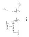
- FIG. 3illustrates a block diagram of an exemplary embodiment of the present invention
- FIG. 4illustrates a transmitter chain embodying the present invention
- FIG. 5illustrates a block diagram of a phase to frequency conversion process
- FIG. 6illustrates a block diagram of a second exemplary embodiment of the invention
- FIG. 7illustrates a transmitter chain incorporating the second embodiment
- FIG. 8illustrates a block diagram of a third exemplary embodiment of the present invention.
- EDGEEnhanced Data for GSM Evolution
- the present inventionis preferably incorporated in a mobile terminal 10 , such as a mobile telephone, personal digital assistant, or the like.
- the basic architecture of a mobile terminal 10is represented in FIG. 1 , and may include a receiver front end 12 , a radio frequency transmitter section 14 , an antenna 16 , a duplexer or switch 18 , a baseband processor 20 , a control system 22 , memory 24 , a frequency synthesizer 26 , and an interface 28 .
- the receiver front end 12receives information bearing radio frequency signals from one or more remote transmitters provided by a base station (not shown).
- a low noise amplifier 30amplifies the signal.
- a filter circuit 32minimizes broadband interference in the received signal, while a downconverter 34 downconverts the filtered, received signal to an intermediate or baseband frequency signal, which is then digitized into one or more digital streams.
- the receiver front end 12typically uses one or more mixing frequencies generated by the frequency synthesizer 26 .
- the baseband processor 20processes the digitized, received signal to extract the information or data bits conveyed in the received signal. This processing typically comprises demodulation, decoding, and error correction operations. As such, the baseband processor 20 is generally implemented in one or more digital signal processors (DSPs).
- DSPsdigital signal processors
- the baseband processor 20receives digitized data from the control system 22 , which it encodes for transmission.
- the encoded datais output to the radio frequency transmitter section 14 , where it is used by a modulator 36 to modulate a carrier signal that is at a desired transmit frequency.
- the modulator 36may have an optional memory unit 38 associated therewith.
- Power amplifier 40amplifies the modulated carrier signal to a level appropriate for transmission from the antenna 16 .
- the power amplifier 40provides gain for the signal to be transmitted under control of the power control circuitry 42 , which is preferably controlled by the control system 22 .
- Memory 24may contain software that allows many of these functions to be run. Alternatively, these may be a function of sequential logic structures as is well understood.
- a usermay interact with the mobile terminal 10 via the interface 28 , which may include interface circuitry 44 associated with a microphone 46 , a speaker 48 , a keypad 50 , and a display 52 .
- the interface circuitry 44typically includes analog-to-digital converters, digital-to-analog converters, amplifiers, and the like. Additionally, it may include a voice encoder/decoder, in which case it may communicate directly with the baseband processor 20 .
- the microphone 46will typically convert audio input, such as the user's voice, into an electrical signal, which is then digitized and passed directly or indirectly to the baseband processor 20 . Audio information encoded in the received signal is recovered by the baseband processor 20 , and converted into an analog signal suitable for driving speaker 48 by the interface circuitry 44 .
- the keypad 50 and display 52enable the user to interact with the mobile terminal 10 , input numbers to be dialed and address book information, or the like, as well as monitor call progress information.
- the present inventionis well-suited for incorporation into a mobile terminal, such as the mobile terminal 10 just described, the present invention is also well-suited for use in wireless transmitters associated with wireless LANs and the like. As such, the present invention is not limited to a particular apparatus.
- the modulator 36directs two signals to the power amplifier 40 .
- a polar modulator 36directed an amplitude signal (r) and a phase signal ( ⁇ ) to the power amplifier 40 .
- the amplitude signal (r)controlled the power supply voltage of the power amplifier 40 , potentially replacing or including the power control circuitry 42 , while the phase signal ( ⁇ ) was amplified by the power amplifier 40 to create A DESIRED ⁇ DESIRED .
- the output (A O ⁇ O ) of the power amplifier 40was corrupted by AM to PM conversion within the non-linear power amplifier 40 , represented by ⁇ (r), and AM to AM conversion, represented by A(r), resulting in an output signal of A DESIRED *A(r) ⁇ DESIRED + ⁇ (r).
- the present inventioncorrects the AM to PM conversion within the output by preliminarily distorting the phase signal such that when it is converted to a frequency signal and amplified by the power amplifier 40 , the predistortion element cancels the AM to PM conversion distortion element introduced by the amplitude signal (r).
- Thisis illustrated in a simplified format in FIG. 3 , wherein the amplitude signal (r) is split by a polar converter 54 within the modulator 36 and directed to a compensator 56 , where a predistortion signal ⁇ ′(r) is generated and then negatively added to the phase signal by an adder 58 .
- the combined signal ( ⁇ ′(r))expressed as an equivalent frequency signal, is amplified by the power amplifier 40 .
- the power amplifier 40imposes a transfer function upon the combined signal and generates ⁇ DESIRED ⁇ (r) from the combined signal.
- the distortion of the amplitude signalis added, and the ⁇ (r) terms cancel out, leaving A DESIRED *A(r) ⁇ DESIRED .
- the present inventionmay be situated in the radio frequency transmitter section 14 , as better illustrated in FIG. 4 .
- the radio frequency transmitter section 14and particularly the modulator 36 , may include several components, including a serial interface 60 , a mapping module 62 , first and second filters 64 , 66 , and the aforementioned polar converter 54 .
- Other components of the modulator 36will be discussed below.
- the serial interface 60receives Non-Return to Zero (NRZ) serial data from the baseband processor 20 at the bit rate of the system.
- NRZ datamay be a 1B1B code with one line bit for each associated binary bit.
- the modulation scheme for the modulator 36uses an EDGE modulation scheme, and thus, the bit rate is 812.5 kbps.
- This datais passed to the mapping module 62 , where the data is grouped into symbols of three consecutive data bits, Grey coded, and rotated by 3 ⁇ /8 on each symbol as per European Telecommunications Standards Institute (ETSI) specifications. The resulting symbol is mapped to one of sixteen points in an I, Q constellation.
- ETSIEuropean Telecommunications Standards Institute
- Both the I and the Q components for each pointare then filtered by the first and second filters 64 , 66 respectively.
- the first and second filters 64 , 66are EDGE finite impulse response (FIR) filters. This, as dictated by the ETSI specifications, shapes the response between symbol times.
- both the I and Q componentsare sent to the polar converter 54 .
- the polar converter 54uses a classical CORDIC (coordinate rotation digital computer) algorithm or like rectangular to polar conversion technique. Thus, the polar converter 54 generates phase ( ⁇ ) and amplitude (r) equivalent signals. Further information about CORDIC algorithms may be found in Proceedings of the 1998 ACM/SIGDA Sixth International Symposium On Field Programmable Gate Arrays by Ray Andraka, February 22-24, pp. 191-200 and “The CORDIC Trigonometric Computing Technique” by Jack E. Volder IRE Trans on Elect. Computers , p. 330, 1959, both of which are hereby incorporated by reference in their entirety.
- the amplitude signal (r)is split and directed to the compensator 56 .
- the compensator 56introduces a compensation term to the phase signal that, after further processing, counteracts the distortion introduced by the AM to PM conversion in the power amplifier 40 .
- the compensator 56acts to create a sum of polynomials along the lines of the following equation:
- ⁇ i0 N ⁇ ⁇ C i ⁇ ( r ⁇ ( t ) ) i
- ⁇ ′(r)has an offset term, a linear term, a quadratic term, and a cubic term selectable by the hardware implementation.
- the coefficients C iare associated with the control system 22 , and particularly in non-volatile memory 24 associated therewith.
- the coefficientsmay be stored in memory 38 if such is present.
- the coefficientsmay be stored as a look up table. It is further possible that the coefficients are stored as a function of sequential steps performed by hardware. The coefficients are determined through a best fit analysis of a function that substantially matches the unamplified inverse of ⁇ (r). In a more preferred embodiment, a piecewise function is created with each piece being determined by a given power level. This is done to improve the fit between the functions.
- ⁇ ′(r)might not fit well at the ends or perhaps in the middle of the relevant range of values.
- ⁇ ′(r)might not fit well at the ends or perhaps in the middle of the relevant range of values.
- a good fit between the equationsmay be achieved throughout the curve of relevant values.
- a set of coefficientsis created for each 2 dBm power step. This corresponds to the power steps defined in the ETSI standards.
- a programsuch as MATHCAD may be used to derive a match to an empirical power amplifier curve. The coefficients may be tested through an ADS simulation or the like.
- the output of the compensator 56is subtracted from the phase signal ( ⁇ ) by the adder 58 to create a combined signal.
- the adder 58is also termed herein a combiner.
- the output of the adder 58(the combined signal) is directed to a phase to frequency converter 68 where the output is converted to a frequency signal (f). More detail on the phase to frequency converter 68 is provided below with reference to FIG. 5 .
- magnitude adjusters 70 , 72then adjust the magnitude of the r and f signals to a level expected by the time aligner 74 , such that they comply with the appropriate standard.
- a relative time delayis applied as necessary to the signals for best Error Vector Magnitude (EVM) and spectrum by the time aligner 74 . Because these are preferably digital components, concerns about variations in analog components and the corresponding variation in time delays downstream are minimized.
- EVMError Vector Magnitude
- the r and f signalsseparate and proceed by different paths, an amplitude signal processing path and a frequency signal processing path, to the power amplifier 40 .
- the amplitude signalis converted to an analog signal by D/A converter 76 .
- a ramping functionmay be combined with the amplitude signal prior to digital-to-analog conversion.
- the output of the D/A converter 76is used to set the collector voltage on the power amplifier 40 through a collector regulator 78 .
- V 2 /R outR out is not shown, but is effectively the load on the power amplifier 40 ). This is sometimes known as “plate modulation”.
- the frequency signalis directed to a digital filter 80 , a digital predistortion filter 82 , and a phase locked loop (PLL) 84 , as is described in commonly invented, commonly owned U.S. patent application Ser. No. 10/139,560, filed May 6, 2002, entitled DIRECT DIGITAL POLAR MODULATOR, which is hereby incorporated by reference in its entirety.
- the PLL 84generates an output at the desired radio frequency.
- the frequency signalis applied to a single port on a fractional N divider within the PLL 84 .
- the PLL 84comprises a reference source that is fed to a phase comparator.
- the phase comparatorcompares the edges of the reference source to the output of the fractional N divider and produces a correction signal.
- the correction signalis low pass filtered and input to a voltage controlled oscillator (VCO).
- VCOvoltage controlled oscillator
- the VCOoutputs a frequency modulated signal at the RF carrier, which in turn is fed back to the fractional N divider.
- the divisor of the fractional N divideris modulated by the frequency signal.
- the phase to frequency converter 68is explicated with reference to FIG. 5 .
- the phase signalarrives and is split into a delay path and a normal path.
- a clock 86controls a delay element 88 in the delay path.
- the output of the delay element 88is subtracted from the normal path by adder 90 .
- the output of the adder 90is multiplied by 2 ⁇ in a multiplier 92 , and a frequency signal (f) is output.
- phase f2 ⁇ ⁇ ⁇ d ( phase ) d t in a digital sense.
- the delay and the subtractionapproximates the derivative as (phase(N) ⁇ phase(N ⁇ 1))/T, where T is the period for the clock 86 .
- Other phase to frequency conversionscould also be used if needed or desired.
- this derivative functioncauses the offset term of the sum of polynomials to be a zero value. However, this does cause an impulse function at the point where the constant is introduced. That is, when the constant changes from one constant to another, such as at the boundary of a piece of the piecewise function, there is effectively a square wave transition. At that point, there would be an instantaneous frequency change. This may create a desired phase offset at the output of the power amplifier 40 . This is particularly useful in a General Packet Radio Service (GPRS) system to avoid phase discontinuities when power levels are switched.
- GPRSGeneral Packet Radio Service
- the compensation signalmay be introduced into the amplitude signal to correct AM to AM conversion.
- AM to AM conversion(A(r)) is caused by the power amplifier 40 having non-linear gain with varying output power.
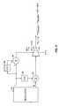
- FIG. 6illustrates, in a very simplified form, the concept of this embodiment of the present invention.
- the amplitude signalis split and sent to a compensator 94 .
- the compensator 94generates a compensation signal A′(r) which is then added back to the amplitude signal by adder 96 .
- FIG. 7represents a more detailed view of how the compensator 94 fits within the modulator 36 .
- Compensator 94acts to create a sum of polynomials along the lines of the following equation:
- N3 and the equation expands to the following:
- a ′( r )C 0 +C 1 r ( t )+ C 2 ( r ( t )) 2 +C 3 ( r ( t )) 3
- A′(r)is termed herein a compensation signal and r(t) is the amplitude of the modulation from the polar modulator 36 . It is readily apparent that A′(r) has an offset term, a linear term, a squared term, and a cubic term.
- the offset term C 0 and the coefficient for the linear term C 1are zero.
- An offset termwould act the same as increasing or decreasing the output power level. As the collector regulator 78 already addresses this, it is not necessary to repeat the control here. Likewise, a linear term would only change the fundamental amplitude and not change the shape of the curve, so a linear term for this compensation signal makes little sense.
- This distortionis A(r).
- the AM to AM distortionhas been canceled.
- the correction termscould have a linear term and an offset term. From a design standpoint, this removes a multiplier from the compensator 94 and inserts a multiplier in place of the adder 96 .
- the concept of canceling the AM to AM conversion with its inverseremains the same.
- the coefficients C iare associated with control system 22 , and particularly in non-volatile memory 24 associated therewith.
- the coefficientsmay be stored in memory 38 if such is present.
- the coefficientsmay be stored in a look up table or the like. It is further possible that the coefficients are created as a function of hardware. The coefficients are determined through a best fit analysis of a function that matches the expected AM to AM distortion A(r). In a more preferred embodiment, a piecewise function is created with each piece being determined by a given power level. This is done to improve the fit between the functions.
- A′(r)might not fit well at the ends or perhaps in the middle of the relevant range of values.
- A′(r)might not fit well at the ends or perhaps in the middle of the relevant range of values.
- a good fit between the equationsmay be achieved throughout the curve of relevant values.
- a set of coefficientsis created for each 2 dBm power step. This corresponds to the power steps defined in the ETSI standards.
- a programsuch as MATHCAD may be used to derive a match to an empirical power amplifier curve.
- the coefficientsmay be tested through an ADS simulation or the like.
- both compensation schemesmay be used simultaneously, although it should be noted that the functions now provide some interaction therebetween so that together both the AM to PM conversion and the AM to AM conversion is canceled.
Landscapes
- Engineering & Computer Science (AREA)
- Computer Networks & Wireless Communication (AREA)
- Signal Processing (AREA)
- Amplifiers (AREA)
Abstract
Description
In this particular case, N=3 and the equation expands to the following:
φ′(r)=C0+C1r(t)+C2(r(t))2+C3(r(t))3
φ′(r) is termed herein the compensation signal. It is readily apparent that φ′(r) has an offset term, a linear term, a quadratic term, and a cubic term selectable by the hardware implementation.
in a digital sense. The delay and the subtraction approximates the derivative as (phase(N)−phase(N−1))/T, where T is the period for the
In this particular case, N=3 and the equation expands to the following:
A′(r)=C0+C1r(t)+C2(r(t))2+C3(r(t))3
A′(r) is termed herein a compensation signal and r(t) is the amplitude of the modulation from the
r′(t)=r(t)+C2(r(t))2+C3(r(t))3
which converts easily to the following:
r′(t)=r(t)*[1+C2(r(t))+C3(r(t))2]
Thus, even though the
Claims (19)
Priority Applications (1)
| Application Number | Priority Date | Filing Date | Title |
|---|---|---|---|
| US10/147,579US7801244B2 (en) | 2002-05-16 | 2002-05-16 | Am to AM correction system for polar modulator |
Applications Claiming Priority (1)
| Application Number | Priority Date | Filing Date | Title |
|---|---|---|---|
| US10/147,579US7801244B2 (en) | 2002-05-16 | 2002-05-16 | Am to AM correction system for polar modulator |
Publications (2)
| Publication Number | Publication Date |
|---|---|
| US20030215026A1 US20030215026A1 (en) | 2003-11-20 |
| US7801244B2true US7801244B2 (en) | 2010-09-21 |
Family
ID=29419041
Family Applications (1)
| Application Number | Title | Priority Date | Filing Date |
|---|---|---|---|
| US10/147,579Active2025-12-06US7801244B2 (en) | 2002-05-16 | 2002-05-16 | Am to AM correction system for polar modulator |
Country Status (1)
| Country | Link |
|---|---|
| US (1) | US7801244B2 (en) |
Cited By (3)
| Publication number | Priority date | Publication date | Assignee | Title |
|---|---|---|---|---|
| US20090291648A1 (en)* | 2008-05-20 | 2009-11-26 | Matsushita Electric Industrial Co., Ltd. | Methods and apparatus for reconstructing amplitude modulation signals in polar modulation transmitters |
| US20100066429A1 (en)* | 2007-01-31 | 2010-03-18 | Panasonic Corporation | Power supply voltage forming device and polar modulation transmission device |
| EP4340218A1 (en)* | 2022-09-13 | 2024-03-20 | Nxp B.V. | Circuit for polar transmitter and method of operating a polar transmitter |
Families Citing this family (47)
| Publication number | Priority date | Publication date | Assignee | Title |
|---|---|---|---|---|
| US7991071B2 (en)* | 2002-05-16 | 2011-08-02 | Rf Micro Devices, Inc. | AM to PM correction system for polar modulator |
| US7801244B2 (en) | 2002-05-16 | 2010-09-21 | Rf Micro Devices, Inc. | Am to AM correction system for polar modulator |
| US7551685B2 (en) | 2003-08-25 | 2009-06-23 | M/A-Com, Inc. | Apparatus, methods and articles of manufacture for signal correction using adaptive phase re-alignment |
| US7254195B2 (en)* | 2003-08-25 | 2007-08-07 | M/A-Com, Inc. | Apparatus, methods and articles of manufacture for dynamic differential delay correction |
| US7298854B2 (en)* | 2002-12-04 | 2007-11-20 | M/A-Com, Inc. | Apparatus, methods and articles of manufacture for noise reduction in electromagnetic signal processing |
| US7502422B2 (en)* | 2003-06-04 | 2009-03-10 | M/A—COM, Inc. | Electromagnetic wave transmitter systems, methods and articles of manufacture |
| US7340007B2 (en)* | 2003-09-16 | 2008-03-04 | M/A-Com, Inc. | Apparatus, methods and articles of manufacture for pre-emphasis filtering of a modulated signal |
| US6806780B2 (en)* | 2003-03-13 | 2004-10-19 | Texas Instruments Incorporated | Efficient modulation compensation of sigma delta fractional phase locked loop |
| US7042958B2 (en)* | 2003-06-04 | 2006-05-09 | Tropian, Inc. | Digital time alignment in a polar modulator |
| JP3844352B2 (en)* | 2003-08-07 | 2006-11-08 | 松下電器産業株式会社 | Transmitter |
| US7116951B2 (en)* | 2003-12-16 | 2006-10-03 | Motorola, Inc. | Transmitter circuit and method for modulation distortion compensation |
| JP4199680B2 (en)* | 2004-01-08 | 2008-12-17 | パナソニック株式会社 | Transmitter |
| US7593480B2 (en)* | 2004-03-10 | 2009-09-22 | Panasonic Corporation | Transmission device and radio communication device |
| US7274748B1 (en) | 2004-06-02 | 2007-09-25 | Rf Micro Devices, Inc. | AM to FM correction system for a polar modulator |
| US7551686B1 (en) | 2004-06-23 | 2009-06-23 | Rf Micro Devices, Inc. | Multiple polynomial digital predistortion |
| US7529523B1 (en) | 2004-08-23 | 2009-05-05 | Rf Micro Devices, Inc. | N-th order curve fit for power calibration in a mobile terminal |
| US7359680B2 (en) | 2004-09-14 | 2008-04-15 | Telefonaktiebolaget Lm Ericsson (Publ) | Delay calibration in polar modulation transmitters |
| US7330073B2 (en)* | 2004-10-06 | 2008-02-12 | Telefonaktiebolaget L M Ericsson (Publ) | Arbitrary waveform predistortion table generation |
| DE102005026927B4 (en)* | 2004-12-08 | 2014-12-24 | Fraunhofer-Gesellschaft zur Förderung der angewandten Forschung e.V. | Method and device for generating an output signal with reduced outer band emission |
| US7474878B1 (en) | 2005-03-02 | 2009-01-06 | Rf Micro Devices, Inc. | Closed loop polar modulation system with open loop option at low power levels |
| US7426372B2 (en)* | 2005-03-31 | 2008-09-16 | M/A-Com Eurotec B.V. | Piecewise linearizer circuit for radio frequency amplification |
| US8224265B1 (en)* | 2005-06-13 | 2012-07-17 | Rf Micro Devices, Inc. | Method for optimizing AM/AM and AM/PM predistortion in a mobile terminal |
| US7307570B2 (en)* | 2005-07-20 | 2007-12-11 | M/A-Com, Inc. | Method and apparatus to emulate a filter |
| US7436339B2 (en)* | 2005-07-20 | 2008-10-14 | M/A-Com, Inc. | Method and apparatus to emulate a filter using digital elements |
| US7539462B2 (en)* | 2005-08-09 | 2009-05-26 | Freescale Semiconductor, Inc. | Configurable multi-mode modulation system and transmitter |
| US20070087770A1 (en)* | 2005-10-14 | 2007-04-19 | Hong Gan | Methods and apparatuses for transmission power control in a wireless communication system |
| US8884714B2 (en)* | 2005-12-22 | 2014-11-11 | Pine Valley Investments, Inc. | Apparatus, system, and method for digital base modulation of power amplifier in polar transmitter |
| US7599448B2 (en)* | 2006-02-03 | 2009-10-06 | Pine Valley Investments, Inc. | Multi-mode selectable modulation architecture calibration and power control apparatus, system, and method for radio frequency power amplifier |
| US7877060B1 (en) | 2006-02-06 | 2011-01-25 | Rf Micro Devices, Inc. | Fast calibration of AM/PM pre-distortion |
| US7599418B2 (en) | 2006-02-16 | 2009-10-06 | Pine Valley Investments, Inc. | Method and apparatus for a frequency hopper |
| US20070216455A1 (en)* | 2006-03-17 | 2007-09-20 | M/A-Com, Inc. | Partial cascode delay locked loop architecture |
| US7962108B1 (en) | 2006-03-29 | 2011-06-14 | Rf Micro Devices, Inc. | Adaptive AM/PM compensation |
| US7596184B2 (en)* | 2006-03-30 | 2009-09-29 | Pine Valley Investments, Inc. | Apparatus, system, and method for amplitude-phase synchronization in polar transmitter |
| WO2007122562A2 (en)* | 2006-04-21 | 2007-11-01 | Nxp B.V. | A modulator for amplitude-modulating a signal |
| KR100777460B1 (en)* | 2006-06-16 | 2007-11-21 | 삼성전자주식회사 | Polar Transmitter Improves Modulation Rate Using Multiphase Generator |
| US7689182B1 (en) | 2006-10-12 | 2010-03-30 | Rf Micro Devices, Inc. | Temperature compensated bias for AM/PM improvement |
| US8050783B2 (en)* | 2007-03-12 | 2011-11-01 | Pine Valley Investments, Inc. | System and method for pre-distorting a device input |
| US7869543B2 (en)* | 2007-03-13 | 2011-01-11 | Pine Valley Investments, Inc. | System and method for synchronization, power control, calibration, and modulation in communication transmitters |
| US8009765B2 (en)* | 2007-03-13 | 2011-08-30 | Pine Valley Investments, Inc. | Digital polar transmitter |
| US8009762B1 (en)* | 2007-04-17 | 2011-08-30 | Rf Micro Devices, Inc. | Method for calibrating a phase distortion compensated polar modulated radio frequency transmitter |
| US8081710B2 (en)* | 2007-11-08 | 2011-12-20 | Pine Valley Investments, Inc. | System and method for corrected modulation with nonlinear power amplification |
| US7983359B2 (en)* | 2008-02-07 | 2011-07-19 | Pine Valley Investments, Inc. | Synchronization techniques for polar transmitters |
| US8233852B2 (en)* | 2008-04-04 | 2012-07-31 | Pine Valley Investments, Inc. | Calibration techniques for non-linear devices |
| US8489042B1 (en) | 2009-10-08 | 2013-07-16 | Rf Micro Devices, Inc. | Polar feedback linearization |
| US8258835B1 (en)* | 2011-06-15 | 2012-09-04 | Asahi Kasei Microdevices Corporation | Cancellation system for phase jumps at loop gain changes in fractional-N frequency synthesizers |
| WO2020125790A1 (en)* | 2018-12-21 | 2020-06-25 | Huawei Technologies Co., Ltd. | Polar transmitter with feedthrough compensation |
| US10735229B1 (en)* | 2019-05-28 | 2020-08-04 | Qualcomm Incorporated | Limiter for trasmitters |
Citations (119)
| Publication number | Priority date | Publication date | Assignee | Title |
|---|---|---|---|---|
| US3900823A (en) | 1973-03-28 | 1975-08-19 | Nathan O Sokal | Amplifying and processing apparatus for modulated carrier signals |
| US4389618A (en) | 1981-04-15 | 1983-06-21 | The United States Of America As Represented By The Secretary Of The Navy | Adaptive feed-forward system |
| US4609881A (en) | 1983-05-17 | 1986-09-02 | Marconi Instruments Limited | Frequency synthesizers |
| US4837786A (en) | 1986-08-07 | 1989-06-06 | Comstream Corporation | Technique for mitigating rain fading in a satellite communications system using quadrature phase shift keying |
| US4968908A (en) | 1989-03-06 | 1990-11-06 | The United States Of America As Represented By The Secretary Of Commerce | Method and apparatus for wide band phase modulation |
| US5055802A (en) | 1990-04-30 | 1991-10-08 | Motorola, Inc. | Multiaccumulator sigma-delta fractional-n synthesis |
| US5079522A (en) | 1989-10-20 | 1992-01-07 | Marconi Instruments Limited | Variable frequency signal generator |
| US5313411A (en) | 1992-02-26 | 1994-05-17 | Nec Corporation | Adaptive receiver capable of achieving both of matched filtering function and carrier recovery function |
| US5430416A (en) | 1994-02-23 | 1995-07-04 | Motorola | Power amplifier having nested amplitude modulation controller and phase modulation controller |
| US5444415A (en) | 1993-03-01 | 1995-08-22 | Texas Instruments Incorporated | Modulation and demodulation of plural channels using analog and digital components |
| US5524286A (en)* | 1993-12-14 | 1996-06-04 | Alcatel Italia S.P.A. | Baseband predistortion system for the adaptive linearization of power amplifiers |
| US5598436A (en) | 1993-06-29 | 1997-01-28 | U.S. Philips Corporation | Digital transmission system with predistortion |
| US5608353A (en) | 1995-03-29 | 1997-03-04 | Rf Micro Devices, Inc. | HBT power amplifier |
| US5617450A (en) | 1993-10-26 | 1997-04-01 | Fujitsu Limited | Digital subscriber loop interface unit |
| US5822011A (en) | 1995-09-15 | 1998-10-13 | Thomson Consumer Electronics, Inc. | Apparatus for detecting noise in a color video signal |
| US5900778A (en) | 1997-05-08 | 1999-05-04 | Stonick; John T. | Adaptive parametric signal predistorter for compensation of time varying linear and nonlinear amplifier distortion |
| US5952895A (en) | 1998-02-23 | 1999-09-14 | Tropian, Inc. | Direct digital synthesis of precise, stable angle modulated RF signal |
| US6008703A (en) | 1997-01-31 | 1999-12-28 | Massachusetts Institute Of Technology | Digital compensation for wideband modulation of a phase locked loop frequency synthesizer |
| US6101224A (en) | 1998-10-07 | 2000-08-08 | Telefonaktiebolaget Lm Ericsson | Method and apparatus for generating a linearly modulated signal using polar modulation |
| US6115684A (en)* | 1996-07-30 | 2000-09-05 | Atr Human Information Processing Research Laboratories | Method of transforming periodic signal using smoothed spectrogram, method of transforming sound using phasing component and method of analyzing signal using optimum interpolation function |
| US6130579A (en) | 1999-03-29 | 2000-10-10 | Rf Micro Devices, Inc. | Feed-forward biasing for RF amplifiers |
| US6191656B1 (en) | 1999-07-23 | 2001-02-20 | Rf Micro Devices, Inc. | High efficiency, unilateral dual stage RF amplifier |
| US6211747B1 (en) | 1998-05-29 | 2001-04-03 | Motorola, Inc. | Wideband modulated fractional-N frequency synthesizer |
| US6229395B1 (en) | 1999-10-01 | 2001-05-08 | Rf Micro Devices, Inc. | Differential transconductance amplifier |
| US6236703B1 (en) | 1998-03-31 | 2001-05-22 | Philsar Semiconductor Inc. | Fractional-N divider using a delta-sigma modulator |
| US6236687B1 (en) | 1999-02-26 | 2001-05-22 | Trw Inc. | Decision directed phase locked loop (DD-PLL) for use with short block codes in digital communication systems |
| US6236837B1 (en)* | 1998-07-30 | 2001-05-22 | Motorola, Inc. | Polynomial Predistortion linearizing device, method, phone and base station |
| US6240278B1 (en) | 1998-07-30 | 2001-05-29 | Motorola, Inc. | Scalar cost function based predistortion linearizing device, method, phone and basestation |
| US6246286B1 (en) | 1999-10-26 | 2001-06-12 | Telefonaktiebolaget Lm Ericsson | Adaptive linearization of power amplifiers |
| US6271727B1 (en) | 1999-08-06 | 2001-08-07 | Rf Micro Devices, Inc. | High isolation RF power amplifier with self-bias attenuator |
| US6275685B1 (en) | 1998-12-10 | 2001-08-14 | Nortel Networks Limited | Linear amplifier arrangement |
| US20010022532A1 (en) | 1999-12-21 | 2001-09-20 | Dolman Graham Ainsley | Phase and amplitude detector and method of determining errors |
| US6295442B1 (en) | 1998-12-07 | 2001-09-25 | Ericsson Inc. | Amplitude modulation to phase modulation cancellation method in an RF amplifier |
| USRE37407E1 (en) | 1996-01-30 | 2001-10-16 | Spectrian Corporation | Polar envelope correction mechanism for enhancing linearity of RF/microwave power amplifier |
| US6307364B1 (en) | 1999-08-27 | 2001-10-23 | Rf Micro Devices, Inc. | Power sensor for RF power amplifier |
| US6329809B1 (en) | 1999-08-27 | 2001-12-11 | Rf Micro Devices, Inc. | RF power amplifier output power sensor |
| US6335767B1 (en)* | 1998-06-26 | 2002-01-01 | Harris Corporation | Broadcast transmission system with distributed correction |
| US20020021764A1 (en) | 1998-12-24 | 2002-02-21 | Harri Posti | Multi-frequency transmitter using predistortion and a method of transmitting |
| US6356150B1 (en) | 2000-01-21 | 2002-03-12 | Rf Micro Devices, Inc. | Portable integrated switching power amplifier |
| US6359950B2 (en) | 1998-09-03 | 2002-03-19 | Infineon Technologies. | Digital PLL (phase-locked loop) frequency synthesizer |
| US6366177B1 (en)* | 2000-02-02 | 2002-04-02 | Tropian Inc. | High-efficiency power modulators |
| US20020041210A1 (en) | 2000-05-11 | 2002-04-11 | Andrew Booth | Linear amplifier arrangement |
| US20020044014A1 (en)* | 1999-07-13 | 2002-04-18 | Wright Andrew S. | Amplifier measurement and modeling processes for use in generating predistortion parameters |
| US6377784B2 (en) | 1999-02-09 | 2002-04-23 | Tropian, Inc. | High-efficiency modulation RF amplifier |
| US6392487B1 (en) | 2000-08-02 | 2002-05-21 | Rf Micro Devices, Inc | Variable gain amplifier |
| US20020060606A1 (en)* | 2000-10-12 | 2002-05-23 | Tore Andre | Method and apparatus for reducing distortion |
| US20020093378A1 (en) | 2000-12-15 | 2002-07-18 | Nielsen Per Asbeck | Amplifier circuit, radio transmitter, method and use |
| US20020113905A1 (en) | 2000-12-28 | 2002-08-22 | Lg Electronics Inc. | Linearization compensation system of digital TV relay apparatus and method thereof |
| US6462617B1 (en) | 2001-06-08 | 2002-10-08 | Lucent Technologies Inc. | Method and apparatus for calculating the predistortion function from a power amplifier model |
| US20020160821A1 (en) | 2001-04-27 | 2002-10-31 | Muhammad Kaikati | Power control apparatus, and associated method, for a sending station of a communication system |
| US20020167923A1 (en) | 2001-01-26 | 2002-11-14 | Andrew Sendonaris | Method and apparatus for estimating channel characteristics using pilot and non-pilot data |
| US6504885B1 (en) | 1998-06-12 | 2003-01-07 | Cadence Design Systems, Inc. | System and method for modeling mixed signal RF circuits in a digital signal environment |
| US20030020538A1 (en) | 2001-06-07 | 2003-01-30 | Jaehyeong Kim | Method and apparatus for modeling and estimating the characteristics of a power amplifier by retaining even-order terms in estimating characteristics |
| US6522121B2 (en) | 2001-03-20 | 2003-02-18 | Eni Technology, Inc. | Broadband design of a probe analysis system |
| US20030087617A1 (en) | 1999-08-10 | 2003-05-08 | Aki Shohara | Radio frequency control for communication systems |
| US6581082B1 (en) | 2000-02-22 | 2003-06-17 | Rockwell Collins | Reduced gate count differentiator |
| US20030133518A1 (en) | 2002-01-11 | 2003-07-17 | Rf Micro Devices | Estimation and correction of DC offset in the presence of frequency offset |
| US20030161487A1 (en) | 2002-02-28 | 2003-08-28 | Husted Paul J. | Method and apparatus for transient frequency distortion compensation |
| US20030179830A1 (en)* | 2002-03-25 | 2003-09-25 | Eidson Donald B. | Efficient, high fidelity transmission of modulation schemes through power-constrained remote relay stations by local transmit predistortion and local receiver feedback |
| US20030197559A1 (en) | 2002-04-23 | 2003-10-23 | Fadhel Ghannouchi | Active predistorting linearizer with agile bypass circuit for safe mode operation |
| US20030197558A1 (en) | 2002-04-18 | 2003-10-23 | Agere Systems Inc. | Adaptive predistortion system and a method of adaptively predistorting a signal |
| US6642786B1 (en) | 2002-08-15 | 2003-11-04 | Electronics And Telecommunications Research Institute | Piecewise polynomial predistortion method and apparatus for compensating nonlinear distortion of high power amplifier |
| US20030215026A1 (en) | 2002-05-16 | 2003-11-20 | Hietala Alexander Wayne | AM to AM correction system for polar modulator |
| US20030215025A1 (en) | 2002-05-16 | 2003-11-20 | Hietala Alexander Wayne | AM to PM correction system for polar modulator |
| US20030227342A1 (en) | 2002-06-07 | 2003-12-11 | Dongtai Liu | Multimode modulator employing a phase lock loop for wireless communications |
| US6693468B2 (en) | 2001-06-12 | 2004-02-17 | Rf Micro Devices, Inc. | Fractional-N synthesizer with improved noise performance |
| US6701134B1 (en) | 2002-11-05 | 2004-03-02 | Rf Micro Devices, Inc. | Increased dynamic range for power amplifiers used with polar modulation |
| US6700929B1 (en) | 2000-07-31 | 2004-03-02 | Rf Micro Devices, Inc. | Method and apparatus for multipath parameter estimation in spread-spectrum communications systems |
| US6701138B2 (en) | 2001-06-11 | 2004-03-02 | Rf Micro Devices, Inc. | Power amplifier control |
| US6720831B2 (en) | 2002-04-26 | 2004-04-13 | Rf Micro Devices, Inc. | Power amplifier protection circuit |
| US6724265B2 (en) | 2002-06-14 | 2004-04-20 | Rf Micro Devices, Inc. | Compensation for oscillator tuning gain variations in frequency synthesizers |
| US6724252B2 (en) | 2002-02-21 | 2004-04-20 | Rf Micro Devices, Inc. | Switched gain amplifier circuit |
| US6724831B1 (en)* | 1999-01-07 | 2004-04-20 | Fujitsu Limited | Pre-distortion apparatus and method thereof |
| US6728324B1 (en) | 2000-07-31 | 2004-04-27 | Rf Micro Devices, Inc. | Method and apparatus for multipath signal compensation in spread-spectrum communications systems |
| US6731145B1 (en) | 2002-08-09 | 2004-05-04 | Rf Micro Devices, Inc. | Phase-locked loop having loop gain and frequency response calibration |
| US6735419B2 (en)* | 2001-01-18 | 2004-05-11 | Motorola, Inc. | High efficiency wideband linear wireless power amplifier |
| US6748204B1 (en) | 2000-10-17 | 2004-06-08 | Rf Micro Devices, Inc. | Mixer noise reduction technique |
| US20040121741A1 (en) | 2002-12-16 | 2004-06-24 | Nortel Networks Corporation | Adaptive controller for linearization of transmitter with impairments |
| US20040131129A1 (en) | 2002-09-30 | 2004-07-08 | Gerald Harron | Method and apparatus for reducing the power consumption of the power amplifier used in a QAM modulator |
| US6782244B2 (en) | 2001-03-16 | 2004-08-24 | Rf Micro Devices, Inc. | Segmented power amplifier and method of control |
| US20040183511A1 (en) | 2003-03-17 | 2004-09-23 | Rf Micro Devices, Inc. | DC-DC converter with reduced electromagnetic interference |
| US6798843B1 (en) | 1999-07-13 | 2004-09-28 | Pmc-Sierra, Inc. | Wideband digital predistortion linearizer for nonlinear amplifiers |
| US6801086B1 (en)* | 2002-04-03 | 2004-10-05 | Andrew Corporation | Adaptive digital pre-distortion using amplifier model that incorporates frequency-dependent non-linearities |
| US20040198414A1 (en) | 2002-03-19 | 2004-10-07 | Hunton Matthew J. | System and method for eliminating signal zero crossings in single and multiple channel communication systems |
| US6807406B1 (en) | 2000-10-17 | 2004-10-19 | Rf Micro Devices, Inc. | Variable gain mixer circuit |
| US20040208157A1 (en) | 2001-10-22 | 2004-10-21 | Brian Sander | Multi-mode communications transmitter |
| US6816718B2 (en) | 2002-02-07 | 2004-11-09 | Rf Micro Devices, Inc. | DC offset correction using dummy amplifier |
| US6819914B2 (en) | 2002-02-07 | 2004-11-16 | Rf Micro Devices, Inc. | Differential mixer injection with optional step gain control |
| US6819941B2 (en) | 2001-10-11 | 2004-11-16 | Rf Micro Devices, Inc. | Single output stage power amplification for multimode applications |
| US6831506B1 (en) | 2003-09-17 | 2004-12-14 | Rf Micro Devices, Inc. | Reconfigurable filter architecture |
| US6834084B2 (en) | 2002-05-06 | 2004-12-21 | Rf Micro Devices Inc | Direct digital polar modulator |
| US6836517B2 (en)* | 1999-12-28 | 2004-12-28 | Fujitsu Limited | Distortion compensating apparatus |
| US20050002470A1 (en) | 2003-07-03 | 2005-01-06 | Icefyre Semiconductor Corporation | Predistortion circuit for a transmit system |
| US20050018765A1 (en) | 2003-04-25 | 2005-01-27 | Endres Thomas J. | Decision feedback equalization with fractionally-spaced feedback data |
| US6901514B1 (en) | 1999-06-01 | 2005-05-31 | Digital Video Express, L.P. | Secure oblivious watermarking using key-dependent mapping functions |
| US6901039B1 (en) | 1999-04-15 | 2005-05-31 | Mitsumi Electric Co., Ltd. | Writable optical drive with dynamically variable linear velocity to prevent buffer under-run |
| US6903604B2 (en) | 2001-06-07 | 2005-06-07 | Lucent Technologies Inc. | Method and apparatus for modeling and estimating the characteristics of a power amplifier |
| US6914943B2 (en) | 1999-03-31 | 2005-07-05 | Kabushiki Kaisha Toshiba | Signal modulation circuit and signal modulation method |
| US20050195919A1 (en) | 2004-03-03 | 2005-09-08 | Armando Cova | Digital predistortion system and method for high efficiency transmitters |
| US6975688B2 (en)* | 2000-09-07 | 2005-12-13 | Telefonaktiebolaget Lm Ericsson (Publ) | Off-line MCPA calibration |
| USH2143H1 (en)* | 1998-06-19 | 2006-02-07 | The United States Of America As Represented By The Secretary Of The Navy | System and a method of operation thereof for analyzing the performance of a tape recorder |
| US7010280B1 (en)* | 1998-11-19 | 2006-03-07 | Cadence Design Systems Inc. | Linear RF power amplifier and transmitter |
| US7010276B2 (en) | 2001-04-11 | 2006-03-07 | Tropian, Inc. | Communications signal amplifiers having independent power control and amplitude modulation |
| US7012969B2 (en) | 1999-12-28 | 2006-03-14 | Fujitsu Limited | Distortion compensating apparatus |
| US20060071711A1 (en) | 2004-10-06 | 2006-04-06 | Jonas Persson | Arbitrary waveform predistortion table generation |
| US7054385B2 (en)* | 2001-10-22 | 2006-05-30 | Tropian, Inc. | Reduction of average-to-minimum power ratio in communications signals |
| US20060203899A1 (en) | 2005-02-03 | 2006-09-14 | Gee David M | Method of equalising a channel and apparatus therefor |
| US7109791B1 (en) | 2004-07-09 | 2006-09-19 | Rf Micro Devices, Inc. | Tailored collector voltage to minimize variation in AM to PM distortion in a power amplifier |
| US7113551B2 (en) | 2002-07-25 | 2006-09-26 | Intersil Corporation | Transmitter with limited spectral regrowth and method therefor |
| US20060280502A1 (en) | 2005-06-08 | 2006-12-14 | Hitachi Communication Technologies, Ltd. | Optical access network system |
| US20070110199A1 (en) | 2005-11-15 | 2007-05-17 | Afshin Momtaz | Receive equalizer with adaptive loops |
| US20070190952A1 (en) | 2006-02-15 | 2007-08-16 | Texas Instruments Incorporated | Linearization of a transmit amplifier |
| US7349490B2 (en) | 2003-04-16 | 2008-03-25 | Powerwave Technologies, Inc. | Additive digital predistortion system employing parallel path coordinate conversion |
| US20080219332A1 (en) | 2007-03-05 | 2008-09-11 | Qualcomm Incorporated | Apparatus and methods accounting for automatic gain control in a multi carrier system |
| US7457586B1 (en) | 2005-03-15 | 2008-11-25 | Rf Micro Devices, Inc. | Method of in-device phase measurement and correlation to programmable factors |
| US20080310617A1 (en) | 2007-06-14 | 2008-12-18 | Infineon Technologies Ag | Transmission Links |
| US7529523B1 (en) | 2004-08-23 | 2009-05-05 | Rf Micro Devices, Inc. | N-th order curve fit for power calibration in a mobile terminal |
| US7542520B1 (en)* | 1999-12-02 | 2009-06-02 | Qualcomm Incorporated | Apparatus and method for implementing a low complexity digital modulator |
| US20090252255A1 (en)* | 2008-04-04 | 2009-10-08 | Matsushita Electric Industrial Co., Ltd. | Predistortion methods and apparatus for polar modulation transmitters |
Family Cites Families (6)
| Publication number | Priority date | Publication date | Assignee | Title |
|---|---|---|---|---|
| US5193224A (en)* | 1991-04-24 | 1993-03-09 | Northern Telecom Limited | Adaptive phase control for a power amplifier predistorter |
| US5705959A (en)* | 1996-10-08 | 1998-01-06 | The United States Of America As Represented By The Secretary Of The Air Force | High efficiency low distortion amplification |
| US6590940B1 (en)* | 1999-05-17 | 2003-07-08 | Ericsson Inc. | Power modulation systems and methods that separately amplify low and high frequency portions of an amplitude waveform |
| US6242975B1 (en)* | 1999-05-25 | 2001-06-05 | Conexant Systems, Inc. | Envelope peak and trough limiting to improve amplifier efficiency and distortion characteristics |
| GB2359681B (en)* | 2000-02-25 | 2004-03-10 | Wireless Systems Int Ltd | Switched amplifier |
| US7068984B2 (en)* | 2001-06-15 | 2006-06-27 | Telefonaktiebolaget Lm Ericsson (Publ) | Systems and methods for amplification of a communication signal |
- 2002
- 2002-05-16USUS10/147,579patent/US7801244B2/enactiveActive
Patent Citations (123)
| Publication number | Priority date | Publication date | Assignee | Title |
|---|---|---|---|---|
| US3900823A (en) | 1973-03-28 | 1975-08-19 | Nathan O Sokal | Amplifying and processing apparatus for modulated carrier signals |
| US4389618A (en) | 1981-04-15 | 1983-06-21 | The United States Of America As Represented By The Secretary Of The Navy | Adaptive feed-forward system |
| US4609881A (en) | 1983-05-17 | 1986-09-02 | Marconi Instruments Limited | Frequency synthesizers |
| US4837786A (en) | 1986-08-07 | 1989-06-06 | Comstream Corporation | Technique for mitigating rain fading in a satellite communications system using quadrature phase shift keying |
| US4968908A (en) | 1989-03-06 | 1990-11-06 | The United States Of America As Represented By The Secretary Of Commerce | Method and apparatus for wide band phase modulation |
| US5079522A (en) | 1989-10-20 | 1992-01-07 | Marconi Instruments Limited | Variable frequency signal generator |
| US5055802A (en) | 1990-04-30 | 1991-10-08 | Motorola, Inc. | Multiaccumulator sigma-delta fractional-n synthesis |
| US5313411A (en) | 1992-02-26 | 1994-05-17 | Nec Corporation | Adaptive receiver capable of achieving both of matched filtering function and carrier recovery function |
| US5444415A (en) | 1993-03-01 | 1995-08-22 | Texas Instruments Incorporated | Modulation and demodulation of plural channels using analog and digital components |
| US5598436A (en) | 1993-06-29 | 1997-01-28 | U.S. Philips Corporation | Digital transmission system with predistortion |
| US5617450A (en) | 1993-10-26 | 1997-04-01 | Fujitsu Limited | Digital subscriber loop interface unit |
| US5524286A (en)* | 1993-12-14 | 1996-06-04 | Alcatel Italia S.P.A. | Baseband predistortion system for the adaptive linearization of power amplifiers |
| US5430416A (en) | 1994-02-23 | 1995-07-04 | Motorola | Power amplifier having nested amplitude modulation controller and phase modulation controller |
| US5608353A (en) | 1995-03-29 | 1997-03-04 | Rf Micro Devices, Inc. | HBT power amplifier |
| US5629648A (en) | 1995-03-29 | 1997-05-13 | Rf Micro Devices, Inc. | HBT power amplifier |
| US5822011A (en) | 1995-09-15 | 1998-10-13 | Thomson Consumer Electronics, Inc. | Apparatus for detecting noise in a color video signal |
| USRE37407E1 (en) | 1996-01-30 | 2001-10-16 | Spectrian Corporation | Polar envelope correction mechanism for enhancing linearity of RF/microwave power amplifier |
| US6115684A (en)* | 1996-07-30 | 2000-09-05 | Atr Human Information Processing Research Laboratories | Method of transforming periodic signal using smoothed spectrogram, method of transforming sound using phasing component and method of analyzing signal using optimum interpolation function |
| US6008703A (en) | 1997-01-31 | 1999-12-28 | Massachusetts Institute Of Technology | Digital compensation for wideband modulation of a phase locked loop frequency synthesizer |
| US5900778A (en) | 1997-05-08 | 1999-05-04 | Stonick; John T. | Adaptive parametric signal predistorter for compensation of time varying linear and nonlinear amplifier distortion |
| US5952895A (en) | 1998-02-23 | 1999-09-14 | Tropian, Inc. | Direct digital synthesis of precise, stable angle modulated RF signal |
| US6236703B1 (en) | 1998-03-31 | 2001-05-22 | Philsar Semiconductor Inc. | Fractional-N divider using a delta-sigma modulator |
| US6211747B1 (en) | 1998-05-29 | 2001-04-03 | Motorola, Inc. | Wideband modulated fractional-N frequency synthesizer |
| US6504885B1 (en) | 1998-06-12 | 2003-01-07 | Cadence Design Systems, Inc. | System and method for modeling mixed signal RF circuits in a digital signal environment |
| USH2143H1 (en)* | 1998-06-19 | 2006-02-07 | The United States Of America As Represented By The Secretary Of The Navy | System and a method of operation thereof for analyzing the performance of a tape recorder |
| US6335767B1 (en)* | 1998-06-26 | 2002-01-01 | Harris Corporation | Broadcast transmission system with distributed correction |
| US6236837B1 (en)* | 1998-07-30 | 2001-05-22 | Motorola, Inc. | Polynomial Predistortion linearizing device, method, phone and base station |
| US6240278B1 (en) | 1998-07-30 | 2001-05-29 | Motorola, Inc. | Scalar cost function based predistortion linearizing device, method, phone and basestation |
| US6359950B2 (en) | 1998-09-03 | 2002-03-19 | Infineon Technologies. | Digital PLL (phase-locked loop) frequency synthesizer |
| US6101224A (en) | 1998-10-07 | 2000-08-08 | Telefonaktiebolaget Lm Ericsson | Method and apparatus for generating a linearly modulated signal using polar modulation |
| US7010280B1 (en)* | 1998-11-19 | 2006-03-07 | Cadence Design Systems Inc. | Linear RF power amplifier and transmitter |
| US6295442B1 (en) | 1998-12-07 | 2001-09-25 | Ericsson Inc. | Amplitude modulation to phase modulation cancellation method in an RF amplifier |
| US6275685B1 (en) | 1998-12-10 | 2001-08-14 | Nortel Networks Limited | Linear amplifier arrangement |
| US20020021764A1 (en) | 1998-12-24 | 2002-02-21 | Harri Posti | Multi-frequency transmitter using predistortion and a method of transmitting |
| US6724831B1 (en)* | 1999-01-07 | 2004-04-20 | Fujitsu Limited | Pre-distortion apparatus and method thereof |
| US6377784B2 (en) | 1999-02-09 | 2002-04-23 | Tropian, Inc. | High-efficiency modulation RF amplifier |
| US6236687B1 (en) | 1999-02-26 | 2001-05-22 | Trw Inc. | Decision directed phase locked loop (DD-PLL) for use with short block codes in digital communication systems |
| US6130579A (en) | 1999-03-29 | 2000-10-10 | Rf Micro Devices, Inc. | Feed-forward biasing for RF amplifiers |
| US6285239B1 (en) | 1999-03-29 | 2001-09-04 | Rf Micro Devices, Inc. | Feed-forward biasing for RF amplifiers |
| US6914943B2 (en) | 1999-03-31 | 2005-07-05 | Kabushiki Kaisha Toshiba | Signal modulation circuit and signal modulation method |
| US6901039B1 (en) | 1999-04-15 | 2005-05-31 | Mitsumi Electric Co., Ltd. | Writable optical drive with dynamically variable linear velocity to prevent buffer under-run |
| US6901514B1 (en) | 1999-06-01 | 2005-05-31 | Digital Video Express, L.P. | Secure oblivious watermarking using key-dependent mapping functions |
| US6798843B1 (en) | 1999-07-13 | 2004-09-28 | Pmc-Sierra, Inc. | Wideband digital predistortion linearizer for nonlinear amplifiers |
| US20020044014A1 (en)* | 1999-07-13 | 2002-04-18 | Wright Andrew S. | Amplifier measurement and modeling processes for use in generating predistortion parameters |
| US6191656B1 (en) | 1999-07-23 | 2001-02-20 | Rf Micro Devices, Inc. | High efficiency, unilateral dual stage RF amplifier |
| US6271727B1 (en) | 1999-08-06 | 2001-08-07 | Rf Micro Devices, Inc. | High isolation RF power amplifier with self-bias attenuator |
| US20030087617A1 (en) | 1999-08-10 | 2003-05-08 | Aki Shohara | Radio frequency control for communication systems |
| US6307364B1 (en) | 1999-08-27 | 2001-10-23 | Rf Micro Devices, Inc. | Power sensor for RF power amplifier |
| US6329809B1 (en) | 1999-08-27 | 2001-12-11 | Rf Micro Devices, Inc. | RF power amplifier output power sensor |
| US6229395B1 (en) | 1999-10-01 | 2001-05-08 | Rf Micro Devices, Inc. | Differential transconductance amplifier |
| US6246286B1 (en) | 1999-10-26 | 2001-06-12 | Telefonaktiebolaget Lm Ericsson | Adaptive linearization of power amplifiers |
| US7542520B1 (en)* | 1999-12-02 | 2009-06-02 | Qualcomm Incorporated | Apparatus and method for implementing a low complexity digital modulator |
| US20010022532A1 (en) | 1999-12-21 | 2001-09-20 | Dolman Graham Ainsley | Phase and amplitude detector and method of determining errors |
| US7012969B2 (en) | 1999-12-28 | 2006-03-14 | Fujitsu Limited | Distortion compensating apparatus |
| US6836517B2 (en)* | 1999-12-28 | 2004-12-28 | Fujitsu Limited | Distortion compensating apparatus |
| US6356150B1 (en) | 2000-01-21 | 2002-03-12 | Rf Micro Devices, Inc. | Portable integrated switching power amplifier |
| US6366177B1 (en)* | 2000-02-02 | 2002-04-02 | Tropian Inc. | High-efficiency power modulators |
| US6581082B1 (en) | 2000-02-22 | 2003-06-17 | Rockwell Collins | Reduced gate count differentiator |
| US20020041210A1 (en) | 2000-05-11 | 2002-04-11 | Andrew Booth | Linear amplifier arrangement |
| US6728324B1 (en) | 2000-07-31 | 2004-04-27 | Rf Micro Devices, Inc. | Method and apparatus for multipath signal compensation in spread-spectrum communications systems |
| US6700929B1 (en) | 2000-07-31 | 2004-03-02 | Rf Micro Devices, Inc. | Method and apparatus for multipath parameter estimation in spread-spectrum communications systems |
| US6392487B1 (en) | 2000-08-02 | 2002-05-21 | Rf Micro Devices, Inc | Variable gain amplifier |
| US6975688B2 (en)* | 2000-09-07 | 2005-12-13 | Telefonaktiebolaget Lm Ericsson (Publ) | Off-line MCPA calibration |
| US20020060606A1 (en)* | 2000-10-12 | 2002-05-23 | Tore Andre | Method and apparatus for reducing distortion |
| US6748204B1 (en) | 2000-10-17 | 2004-06-08 | Rf Micro Devices, Inc. | Mixer noise reduction technique |
| US6807406B1 (en) | 2000-10-17 | 2004-10-19 | Rf Micro Devices, Inc. | Variable gain mixer circuit |
| US20020093378A1 (en) | 2000-12-15 | 2002-07-18 | Nielsen Per Asbeck | Amplifier circuit, radio transmitter, method and use |
| US20020113905A1 (en) | 2000-12-28 | 2002-08-22 | Lg Electronics Inc. | Linearization compensation system of digital TV relay apparatus and method thereof |
| US6735419B2 (en)* | 2001-01-18 | 2004-05-11 | Motorola, Inc. | High efficiency wideband linear wireless power amplifier |
| US20020167923A1 (en) | 2001-01-26 | 2002-11-14 | Andrew Sendonaris | Method and apparatus for estimating channel characteristics using pilot and non-pilot data |
| US6782244B2 (en) | 2001-03-16 | 2004-08-24 | Rf Micro Devices, Inc. | Segmented power amplifier and method of control |
| US6522121B2 (en) | 2001-03-20 | 2003-02-18 | Eni Technology, Inc. | Broadband design of a probe analysis system |
| US7010276B2 (en) | 2001-04-11 | 2006-03-07 | Tropian, Inc. | Communications signal amplifiers having independent power control and amplitude modulation |
| US20020160821A1 (en) | 2001-04-27 | 2002-10-31 | Muhammad Kaikati | Power control apparatus, and associated method, for a sending station of a communication system |
| US20030020538A1 (en) | 2001-06-07 | 2003-01-30 | Jaehyeong Kim | Method and apparatus for modeling and estimating the characteristics of a power amplifier by retaining even-order terms in estimating characteristics |
| US6903604B2 (en) | 2001-06-07 | 2005-06-07 | Lucent Technologies Inc. | Method and apparatus for modeling and estimating the characteristics of a power amplifier |
| US6462617B1 (en) | 2001-06-08 | 2002-10-08 | Lucent Technologies Inc. | Method and apparatus for calculating the predistortion function from a power amplifier model |
| US20040072597A1 (en) | 2001-06-11 | 2004-04-15 | Rf Micro Devices, Inc. | Power amplifier control |
| US6701138B2 (en) | 2001-06-11 | 2004-03-02 | Rf Micro Devices, Inc. | Power amplifier control |
| US6693468B2 (en) | 2001-06-12 | 2004-02-17 | Rf Micro Devices, Inc. | Fractional-N synthesizer with improved noise performance |
| US6819941B2 (en) | 2001-10-11 | 2004-11-16 | Rf Micro Devices, Inc. | Single output stage power amplification for multimode applications |
| US7054385B2 (en)* | 2001-10-22 | 2006-05-30 | Tropian, Inc. | Reduction of average-to-minimum power ratio in communications signals |
| US20040208157A1 (en) | 2001-10-22 | 2004-10-21 | Brian Sander | Multi-mode communications transmitter |
| US7158494B2 (en) | 2001-10-22 | 2007-01-02 | Matsushita Electric Industrial Co., Ltd. | Multi-mode communications transmitter |
| US20030133518A1 (en) | 2002-01-11 | 2003-07-17 | Rf Micro Devices | Estimation and correction of DC offset in the presence of frequency offset |
| US6816718B2 (en) | 2002-02-07 | 2004-11-09 | Rf Micro Devices, Inc. | DC offset correction using dummy amplifier |
| US6819914B2 (en) | 2002-02-07 | 2004-11-16 | Rf Micro Devices, Inc. | Differential mixer injection with optional step gain control |
| US6724252B2 (en) | 2002-02-21 | 2004-04-20 | Rf Micro Devices, Inc. | Switched gain amplifier circuit |
| US20030161487A1 (en) | 2002-02-28 | 2003-08-28 | Husted Paul J. | Method and apparatus for transient frequency distortion compensation |
| US20040198414A1 (en) | 2002-03-19 | 2004-10-07 | Hunton Matthew J. | System and method for eliminating signal zero crossings in single and multiple channel communication systems |
| US20030179830A1 (en)* | 2002-03-25 | 2003-09-25 | Eidson Donald B. | Efficient, high fidelity transmission of modulation schemes through power-constrained remote relay stations by local transmit predistortion and local receiver feedback |
| US6801086B1 (en)* | 2002-04-03 | 2004-10-05 | Andrew Corporation | Adaptive digital pre-distortion using amplifier model that incorporates frequency-dependent non-linearities |
| US20030197558A1 (en) | 2002-04-18 | 2003-10-23 | Agere Systems Inc. | Adaptive predistortion system and a method of adaptively predistorting a signal |
| US20030197559A1 (en) | 2002-04-23 | 2003-10-23 | Fadhel Ghannouchi | Active predistorting linearizer with agile bypass circuit for safe mode operation |
| US6720831B2 (en) | 2002-04-26 | 2004-04-13 | Rf Micro Devices, Inc. | Power amplifier protection circuit |
| US6834084B2 (en) | 2002-05-06 | 2004-12-21 | Rf Micro Devices Inc | Direct digital polar modulator |
| US20030215026A1 (en) | 2002-05-16 | 2003-11-20 | Hietala Alexander Wayne | AM to AM correction system for polar modulator |
| US20030215025A1 (en) | 2002-05-16 | 2003-11-20 | Hietala Alexander Wayne | AM to PM correction system for polar modulator |
| US20030227342A1 (en) | 2002-06-07 | 2003-12-11 | Dongtai Liu | Multimode modulator employing a phase lock loop for wireless communications |
| US6724265B2 (en) | 2002-06-14 | 2004-04-20 | Rf Micro Devices, Inc. | Compensation for oscillator tuning gain variations in frequency synthesizers |
| US7113551B2 (en) | 2002-07-25 | 2006-09-26 | Intersil Corporation | Transmitter with limited spectral regrowth and method therefor |
| US6731145B1 (en) | 2002-08-09 | 2004-05-04 | Rf Micro Devices, Inc. | Phase-locked loop having loop gain and frequency response calibration |
| US6642786B1 (en) | 2002-08-15 | 2003-11-04 | Electronics And Telecommunications Research Institute | Piecewise polynomial predistortion method and apparatus for compensating nonlinear distortion of high power amplifier |
| US20040131129A1 (en) | 2002-09-30 | 2004-07-08 | Gerald Harron | Method and apparatus for reducing the power consumption of the power amplifier used in a QAM modulator |
| US6701134B1 (en) | 2002-11-05 | 2004-03-02 | Rf Micro Devices, Inc. | Increased dynamic range for power amplifiers used with polar modulation |
| US20040121741A1 (en) | 2002-12-16 | 2004-06-24 | Nortel Networks Corporation | Adaptive controller for linearization of transmitter with impairments |
| US20040183511A1 (en) | 2003-03-17 | 2004-09-23 | Rf Micro Devices, Inc. | DC-DC converter with reduced electromagnetic interference |
| US7349490B2 (en) | 2003-04-16 | 2008-03-25 | Powerwave Technologies, Inc. | Additive digital predistortion system employing parallel path coordinate conversion |
| US20050018765A1 (en) | 2003-04-25 | 2005-01-27 | Endres Thomas J. | Decision feedback equalization with fractionally-spaced feedback data |
| US20050002470A1 (en) | 2003-07-03 | 2005-01-06 | Icefyre Semiconductor Corporation | Predistortion circuit for a transmit system |
| US6831506B1 (en) | 2003-09-17 | 2004-12-14 | Rf Micro Devices, Inc. | Reconfigurable filter architecture |
| US20050195919A1 (en) | 2004-03-03 | 2005-09-08 | Armando Cova | Digital predistortion system and method for high efficiency transmitters |
| US7109791B1 (en) | 2004-07-09 | 2006-09-19 | Rf Micro Devices, Inc. | Tailored collector voltage to minimize variation in AM to PM distortion in a power amplifier |
| US7529523B1 (en) | 2004-08-23 | 2009-05-05 | Rf Micro Devices, Inc. | N-th order curve fit for power calibration in a mobile terminal |
| US20060071711A1 (en) | 2004-10-06 | 2006-04-06 | Jonas Persson | Arbitrary waveform predistortion table generation |
| US20060203899A1 (en) | 2005-02-03 | 2006-09-14 | Gee David M | Method of equalising a channel and apparatus therefor |
| US7457586B1 (en) | 2005-03-15 | 2008-11-25 | Rf Micro Devices, Inc. | Method of in-device phase measurement and correlation to programmable factors |
| US20060280502A1 (en) | 2005-06-08 | 2006-12-14 | Hitachi Communication Technologies, Ltd. | Optical access network system |
| US20070110199A1 (en) | 2005-11-15 | 2007-05-17 | Afshin Momtaz | Receive equalizer with adaptive loops |
| US20070190952A1 (en) | 2006-02-15 | 2007-08-16 | Texas Instruments Incorporated | Linearization of a transmit amplifier |
| US20080219332A1 (en) | 2007-03-05 | 2008-09-11 | Qualcomm Incorporated | Apparatus and methods accounting for automatic gain control in a multi carrier system |
| US20080310617A1 (en) | 2007-06-14 | 2008-12-18 | Infineon Technologies Ag | Transmission Links |
| US20090252255A1 (en)* | 2008-04-04 | 2009-10-08 | Matsushita Electric Industrial Co., Ltd. | Predistortion methods and apparatus for polar modulation transmitters |
Non-Patent Citations (7)
| Title |
|---|
| Andraka, Ray, "A Survey of CORDIC Algorithms for FPGA Based Computers," Association for Computing Machinery, 0-89791-978-5, 1998. |
| Cusinato, Paolo, "Gain/Bandwidth Programmable PA Control Loop for GSM/CPRS Quad-Band Cellular Handsets," IEEE Journal of Solid-State Circuits, Jun. 2004, 960-966, vol. 39, No. 6, IEEE. |
| Johnson, Jackie, "Power Amplifier Design for Open Loop EDGE Large Signal Polar Modulation Systems," RFDesign, Jun. 2006, pp. 42-50. |
| Johnson, Jackie, "Power Amplifier Design for Open Loop EDGE Large Signal Polar Modulation Systems," RFDesign, Jun. 2006, pp. 42-50. |
| Pinto et al., "Phase Distortion and Error Vector Magnitude for 8-PSK Systems," London Communications Symposium, Sep. 14-15, 2000, University College London, London, England. |
| Volder, Jack E., "The CORDIC Trigonometric Computing Technique," IRE Trans. On Elect Computers p. 330, Sep. 1959. |
| Volder, Jack E., "The CORDIC Trigonometric Computing Technique," IRE Trans. On Elect. Computers p. 330, Sep. 1959. |
Cited By (5)
| Publication number | Priority date | Publication date | Assignee | Title |
|---|---|---|---|---|
| US20100066429A1 (en)* | 2007-01-31 | 2010-03-18 | Panasonic Corporation | Power supply voltage forming device and polar modulation transmission device |
| US7956667B2 (en)* | 2007-01-31 | 2011-06-07 | Panasonic Corporation | Power supply voltage forming device and polar modulation transmission device |
| US20090291648A1 (en)* | 2008-05-20 | 2009-11-26 | Matsushita Electric Industrial Co., Ltd. | Methods and apparatus for reconstructing amplitude modulation signals in polar modulation transmitters |
| US7991366B2 (en)* | 2008-05-20 | 2011-08-02 | Panasonic Corporation | Methods and apparatus for reconstructing amplitude modulation signals in polar modulation transmitters |
| EP4340218A1 (en)* | 2022-09-13 | 2024-03-20 | Nxp B.V. | Circuit for polar transmitter and method of operating a polar transmitter |
Also Published As
| Publication number | Publication date |
|---|---|
| US20030215026A1 (en) | 2003-11-20 |
Similar Documents
| Publication | Publication Date | Title |
|---|---|---|
| US7801244B2 (en) | Am to AM correction system for polar modulator | |
| US7991071B2 (en) | AM to PM correction system for polar modulator | |
| US7288999B1 (en) | Pre-distortion system for a synthesizer having modulation applied in the reference path | |
| US6834084B2 (en) | Direct digital polar modulator | |
| US7545880B1 (en) | Multiple polynomial digital predistortion | |
| US7962108B1 (en) | Adaptive AM/PM compensation | |
| US7817970B2 (en) | Transmitting/receiving device having a polar modulator with variable predistortion | |
| US6914943B2 (en) | Signal modulation circuit and signal modulation method | |
| US6141541A (en) | Method, device, phone and base station for providing envelope-following for variable envelope radio frequency signals | |
| US7977919B1 (en) | Over-voltage protection accounting for battery droop | |
| US7956615B1 (en) | Utilizing computed battery resistance as a battery-life indicator in a mobile terminal | |
| US7962109B1 (en) | Excess current and saturation detection and correction in a power amplifier | |
| US8175553B2 (en) | Wireless communication unit, linearised transmitter circuit and method of linearising therein | |
| US20060050812A1 (en) | System and method for transitioning between modulation formats in adjacent bursts triggering on data flow | |
| US7116951B2 (en) | Transmitter circuit and method for modulation distortion compensation | |
| US7877060B1 (en) | Fast calibration of AM/PM pre-distortion | |
| US20040017858A1 (en) | Mirror translation loop transmitter architecture | |
| US7457586B1 (en) | Method of in-device phase measurement and correlation to programmable factors | |
| US7274748B1 (en) | AM to FM correction system for a polar modulator | |
| US7450916B1 (en) | Excess current and saturation detection and correction in a power amplifier | |
| US7474708B1 (en) | Multimode transmitter architecture | |
| US7333781B1 (en) | Power correction loop for a power amplifier | |
| US7474878B1 (en) | Closed loop polar modulation system with open loop option at low power levels | |
| US8224265B1 (en) | Method for optimizing AM/AM and AM/PM predistortion in a mobile terminal | |
| US8023556B2 (en) | Autonomously generating ramp profiles in a transceiver |
Legal Events
| Date | Code | Title | Description |
|---|---|---|---|
| AS | Assignment | Owner name:RF MICRO DEVICES, INC., NORTH CAROLINA Free format text:ASSIGNMENT OF ASSIGNORS INTEREST;ASSIGNOR:HIETALA, ALEXANDER WAYNE;REEL/FRAME:012918/0656 Effective date:20020516 | |
| STCF | Information on status: patent grant | Free format text:PATENTED CASE | |
| AS | Assignment | Owner name:BANK OF AMERICA, N.A., AS ADMINISTRATIVE AGENT, TE Free format text:NOTICE OF GRANT OF SECURITY INTEREST IN PATENTS;ASSIGNOR:RF MICRO DEVICES, INC.;REEL/FRAME:030045/0831 Effective date:20130319 | |
| FPAY | Fee payment | Year of fee payment:4 | |
| AS | Assignment | Owner name:RF MICRO DEVICES, INC., NORTH CAROLINA Free format text:TERMINATION AND RELEASE OF SECURITY INTEREST IN PATENTS (RECORDED 3/19/13 AT REEL/FRAME 030045/0831);ASSIGNOR:BANK OF AMERICA, N.A., AS ADMINISTRATIVE AGENT;REEL/FRAME:035334/0363 Effective date:20150326 | |
| AS | Assignment | Owner name:QORVO US, INC., NORTH CAROLINA Free format text:MERGER;ASSIGNOR:RF MICRO DEVICES, INC.;REEL/FRAME:039196/0941 Effective date:20160330 | |
| FEPP | Fee payment procedure | Free format text:MAINTENANCE FEE REMINDER MAILED (ORIGINAL EVENT CODE: REM.) | |
| FEPP | Fee payment procedure | Free format text:7.5 YR SURCHARGE - LATE PMT W/IN 6 MO, LARGE ENTITY (ORIGINAL EVENT CODE: M1555); ENTITY STATUS OF PATENT OWNER: LARGE ENTITY | |
| MAFP | Maintenance fee payment | Free format text:PAYMENT OF MAINTENANCE FEE, 8TH YEAR, LARGE ENTITY (ORIGINAL EVENT CODE: M1552); ENTITY STATUS OF PATENT OWNER: LARGE ENTITY Year of fee payment:8 | |
| MAFP | Maintenance fee payment | Free format text:PAYMENT OF MAINTENANCE FEE, 12TH YEAR, LARGE ENTITY (ORIGINAL EVENT CODE: M1553); ENTITY STATUS OF PATENT OWNER: LARGE ENTITY Year of fee payment:12 |