US7800890B1 - Meter cover molding and method - Google Patents
Meter cover molding and methodDownload PDFInfo
- Publication number
- US7800890B1 US7800890B1US12/614,100US61410009AUS7800890B1US 7800890 B1US7800890 B1US 7800890B1US 61410009 AUS61410009 AUS 61410009AUS 7800890 B1US7800890 B1US 7800890B1
- Authority
- US
- United States
- Prior art keywords
- sidewall
- meter
- meter cover
- shield
- edge
- Prior art date
- Legal status (The legal status is an assumption and is not a legal conclusion. Google has not performed a legal analysis and makes no representation as to the accuracy of the status listed.)
- Active
Links
- 238000000465mouldingMethods0.000titleclaimsdescription21
- 238000000034methodMethods0.000titleclaimsdescription14
- 239000000463materialSubstances0.000claimsdescription10
- 238000004891communicationMethods0.000claimsdescription8
- 239000000696magnetic materialSubstances0.000claimsdescription6
- 230000000903blocking effectEffects0.000claimsdescription2
- 238000001914filtrationMethods0.000claimsdescription2
- 230000000694effectsEffects0.000description4
- 238000010438heat treatmentMethods0.000description4
- 230000005855radiationEffects0.000description3
- 239000000853adhesiveSubstances0.000description2
- 230000001070adhesive effectEffects0.000description2
- 210000001503jointAnatomy0.000description2
- 239000012768molten materialSubstances0.000description2
- 238000000638solvent extractionMethods0.000description2
- 230000000007visual effectEffects0.000description2
- 230000006750UV protectionEffects0.000description1
- 230000004075alterationEffects0.000description1
- 238000004040coloringMethods0.000description1
- 230000000295complement effectEffects0.000description1
- 238000010276constructionMethods0.000description1
- 238000005516engineering processMethods0.000description1
- 230000000116mitigating effectEffects0.000description1
- 238000005498polishingMethods0.000description1
- 229920000515polycarbonatePolymers0.000description1
- 239000004417polycarbonateSubstances0.000description1
- 230000004224protectionEffects0.000description1
- 238000006467substitution reactionMethods0.000description1
Images


Classifications
- G—PHYSICS
- G01—MEASURING; TESTING
- G01R—MEASURING ELECTRIC VARIABLES; MEASURING MAGNETIC VARIABLES
- G01R22/00—Arrangements for measuring time integral of electric power or current, e.g. electricity meters
- G01R22/06—Arrangements for measuring time integral of electric power or current, e.g. electricity meters by electronic methods
- G01R22/061—Details of electronic electricity meters
- G01R22/065—Details of electronic electricity meters related to mechanical aspects
Definitions
- the subject matter disclosed hereinrelates to a meter cover.
- a watt-hour metertypically includes a base housing, electro-mechanical components, electronics and a faceplate capturing all of the device's pertinent information.
- the assemblyis typically incased in what is referred to as a meter cover.
- the normal expected function of the coveris to protect the internal components of the meter from its service environment, while still allowing visual and communication access to the device while the meter is in service.
- thermal budgetThe responsibility of a typical meter's design is stay within its thermal budget considering these three partitioned segments. As the demands for high-powered electronics and communication devices grow in the meter's technology, the metering device's internal thermal generation also grows and, therefore, adjustments to the thermal budget partitioning are necessary. In some cases, adjusting the thermal budget partitioning is possible by mitigating the heating effects due to solar radiation and thereby allowing the metering device's portion of the budget to grow. This is typically achieved through solar radiation shielding.
- Typical shielding devices in a watt-hour metermay include, for example, oversized faceplates that shield the internal components, paper-thin polycarbonate sheets that wrap around the periphery of a meter's internal components or opaque covers that include a bonded-on transparent front face.
- a meter coverincludes an opaque portion, including an outer perimeter section to perimetrically fit around a meter, a sidewall extending axially from the perimeter section toward a frontal region and a shield disposed at a portion of a sidewall edge at the frontal region and a transparent portion having an edge, which is shiplap joint bonded with a remaining portion of the sidewall edge and edges of the shield.
- a meter coverincludes an opaque portion to perimetrically fit around a meter, including a sidewall extending axially from a perimeter toward a frontal region and a shield disposed at a portion of a sidewall edge and a transparent portion, including a first part disposed in parallel with the shield and a second part disposed transverse to the first part and in parallel with the sidewall, the transparent portion having an edge bonded with a remaining portion of the sidewall edge and edges of the shield.
- a two-color in molding method to form a meter coverincludes molding an opaque portion to include an outer perimeter section, a sidewall extending axially from the perimeter section toward a frontal region and a shield disposed at a portion of a sidewall edge and molding a transparent portion to have an edge, which is shiplap joint bonded with a remaining portion of the sidewall edge and edges of the shield.
- FIG. 1is a perspective view of a meter cover
- FIG. 2is a side sectional view of the meter cover of FIG. 1 ;
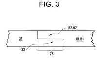
- FIG. 3is an enlarged view of a shiplap joint bond of the meter cover of FIG. 1 ;
- FIG. 4is a perspective view of an interior of the meter cover of FIG. 1 .
- a meter cover 10is provided.
- the meter cover 10encompasses all of the advantages of independent solar shields and ambient light shields of typical meter covers and can be formed as one integral low cost component.
- the meter cover 10is formed in a two-color in molding process that provides a unique balance between opaque and transparent portions of the cover and further provides protection from ambient light and reduces the internal heating effects of solar heating. The meter 10 thereby eliminates the need for additional shielding components or additional assembly processes.
- the meter cover 10includes an opaque portion 20 and a transparent portion 30 .
- the opaque portion 20includes an outer perimeter section 40 , which is sufficiently sized and shaped to perimetrically fit around an exemplary utility meter 50 .
- a sidewall 60extends axially from the perimeter section 40 toward a frontal region 70 .
- a shield 80is disposed at a portion of a sidewall edge 61 at the frontal region 70 .
- the transparent portion 30includes a first part 33 that is disposed in parallel with the shield 80 and a second part 34 that is disposed transverse to the first part 33 and in parallel with the sidewall 60 .
- the transparent portion 30has an edge 31 , which is shiplap joint bonded with a remaining portion of the sidewall edge 61 and exposed edges 81 of the shield 80 .
- the shape of the transparent portion 30extends down into the sidewall 60 for visual reasons and acts as a fundamentally more robust design with respect to impact characteristics. For example, a frontal impact to the meter cover 10 will result in compressive loads being applied to the lower hemisphere region (the second hemisphere 64 described below) and shear loads being applied at the upper hemisphere region (the first hemisphere 63 described below).
- This constructionis unique as compared to other meter covers that have a clear front face only and experience joint damage from impacts due to high shear loads at their joints.
- the shiplap joint bond 75is achieved between the edge 31 of the transparent portion 30 and the sidewall edge 61 as well as the exposed edges 81 of the shield 80 .
- the edge 31includes a flap 32 that overlaps with or is overlapped by complementary flaps 62 and 82 of the sidewall edge 61 and the exposed edges 81 . Bonding between the flaps 32 , 62 and 82 occurs at the molecular level, as will be described below, and requires no additional adhesive or structural fastening features although it is understood that adhesives and/or structural fastening features could be employed for further support. As shown, corners of the flaps 32 , 62 and 82 may also be rounded for improved material flow considerations.
- the perimeter section 40may include a flange 43 .
- the flange 43is connectable with an external surface of the meter 50 and/or a support structure on which the meter 50 is mounted.
- the sidewall 60extends axially from an interior region of the flange 43 toward the frontal region 70 .
- the sidewall 60may include a first hemisphere 63 and a second hemisphere 64 .
- the first hemisphere 63extends axially toward and reaches the frontal region 70 .
- the second hemisphere 64also extends axially toward the frontal region 70 but is axially shorter than the first hemisphere 63 .
- the second hemisphere 64is sufficiently axially short to thereby expose interior components 51 of the meter 50 to observation from an exterior observer.
- the shield 80is oriented in a plane that is transverse to a plane of the sidewall 60 . In this way, the shield 80 may be oriented in parallel with a front face of the meter 50 .
- the shield 80may also be plural in number with at least first and second shield portions 83 , 84 disposed on opposite sides of the meter cover 10 to define an aperture 85 between them and a relatively large opening 86 adjacent to the aperture 85 .
- the aperture 85 and the opening 86may be positioned to expose a display unit 52 and identification information of the meter 50 and are substantially spaced from shield requiring components of the meter 50 .
- the shield portions 83 , 84provide increased shielding for the meter cover 10 as well as increased shade from ambient light and, in some embodiments, are positioned proximate to a shield requiring component of the meter 50 .
- the opaque portion 20 and the transparent portion 30may be further formed to cooperatively define a communication port 90 through which a light emitting diode (LED) or a set of LEDs disposed on the meter 50 can be exposed for connection to an external tool.
- the opaque portion 20is formed to define one or more through-holes 91 exposing each LED disposed on the meter 50 .
- the transparent portion 30is formed to define a raised boss 92 proximate to the through-hole(s) 91 and tubing 93 extending through the through-hole(s) 91 toward the LED.
- the raised boss 92may have a horse-shoe shape and be positioned to bracket the through-hole(s) 91 although this is merely exemplary and it is understood that the shape of the raised boss 92 need only resemble the shape of the external tool and its distance from the through-hole(s) 91 be set in accordance with a size of the external tool.
- the horseshoe shape of the raised boss 92provides axial alignment and radial orientation for the external tool.
- a magnetic material 94is disposed on or in the raised boss 92 of the communication port 90 .
- the magnetic material 94complements magnetic material of the external tool and facilitates connection and alignment between the external tool and the LEDs disposed on the meter 50 .
- At least one of the opaque portion 20 and the transparent portion 30may include an interior surface 100 with ribs 101 formed thereon.
- the ribs 101can be provided in various configurations and may be formed in various shapes to reduce material volume and/or increase surface area. With the ribs 101 , a material strength and heat dissipating characteristics of the opaque portion 20 and the transparent portion 30 can be increased.
- the ribs 101may also provide a translucent effect when and if the opaque portion is substituted with a clear material.
- the opaque portion 20 and the transparent portion 30may each be formed in various shapes and sizes, the opaque portion 20 may be further formed with at least one of ambient light blocking and light filtering materials.
- the opaque portion 20may be relatively lightly colored and/or polished and, in addition, may offer UV protection of the interior components 51 of the meter 50 .
- Both the opaque portion 20 and the transparent portion 30may be formed of materials which are similar or different but which are combinable for performance and cost effectiveness.
- a two-color in molding method to form a meter cover 10includes molding the opaque portion 20 and the transparent portion 30 to include the features discussed above and, in some cases, to include the communication port 90 having the through-hole 91 , the raised boss 92 , the tubing 93 and the magnetic material 94 .
- the methodmay further include forming ribbing on an interior surface of at least one of the opaque portion 20 and the transparent portion 30 and at least one of relatively lightly coloring and polishing a surface of the opaque portion.
- a two-color in molding method to form a meter cover 50includes molding an opaque portion 20 to include the features discussed above, waiting for a predefined period of time during which a material of the opaque portion 20 partially hardens and molding a transparent portion 30 to include the features discussed above.
- the predefined period of timeis sufficiently long to allow the material of the opaque portion 20 to partially harden and still become molten in contact with molten material of the transparent portion 30 during the molding of the transparent portion 30 .
- the predefined period of timeis not so long, however, that the material of the opaque portion 20 completely hardens such that it fails to become sufficiently molten during the molding of the transparent portion 30 .
- molecular level bondingoccurs at and around the shiplap joint of the flaps 32 , 62 and 82 .
Landscapes
- Engineering & Computer Science (AREA)
- Power Engineering (AREA)
- Physics & Mathematics (AREA)
- General Physics & Mathematics (AREA)
- Injection Moulding Of Plastics Or The Like (AREA)
Abstract
Description
Claims (20)
Priority Applications (1)
| Application Number | Priority Date | Filing Date | Title |
|---|---|---|---|
| US12/614,100US7800890B1 (en) | 2009-11-06 | 2009-11-06 | Meter cover molding and method |
Applications Claiming Priority (1)
| Application Number | Priority Date | Filing Date | Title |
|---|---|---|---|
| US12/614,100US7800890B1 (en) | 2009-11-06 | 2009-11-06 | Meter cover molding and method |
Publications (1)
| Publication Number | Publication Date |
|---|---|
| US7800890B1true US7800890B1 (en) | 2010-09-21 |
Family
ID=42733936
Family Applications (1)
| Application Number | Title | Priority Date | Filing Date |
|---|---|---|---|
| US12/614,100ActiveUS7800890B1 (en) | 2009-11-06 | 2009-11-06 | Meter cover molding and method |
Country Status (1)
| Country | Link |
|---|---|
| US (1) | US7800890B1 (en) |
Cited By (7)
| Publication number | Priority date | Publication date | Assignee | Title |
|---|---|---|---|---|
| US8310403B2 (en) | 2010-08-25 | 2012-11-13 | General Electric Company | Antenna attachment scheme for mounting an antenna to a meter |
| USD701784S1 (en)* | 2011-08-01 | 2014-04-01 | Emf Safety, Llc | Smart meter protection device |
| US9612270B2 (en)* | 2015-03-10 | 2017-04-04 | Cooper Technologies Company | Metering continuity tester |
| US10426068B1 (en)* | 2019-01-24 | 2019-09-24 | Jesse I. Danielson | Collapsible radiation shield |
| USD876263S1 (en)* | 2018-07-31 | 2020-02-25 | Landis+Gyr Innovations, Inc. | ANSI electric meter assembly |
| EP3751295A1 (en)* | 2019-06-12 | 2020-12-16 | Carlo Gavazzi Services AG | Electrical rail mount device and cover for an electrical rail mount device |
| WO2024233091A1 (en)* | 2023-05-10 | 2024-11-14 | Itron, Inc. | Utility meter transparent colored nameplate |
Citations (31)
| Publication number | Priority date | Publication date | Assignee | Title |
|---|---|---|---|---|
| US2647235A (en)* | 1947-10-30 | 1953-07-28 | Westinghouse Electric Corp | Thermo-responsive measuring device |
| US2782371A (en) | 1952-03-28 | 1957-02-19 | Weston Electrical Instr Corp | Electrical instrument |
| US3317906A (en) | 1964-07-13 | 1967-05-02 | Monsanto Co | Laminated glass having electrically operated instrument indicator means embedded in the interlayer |
| US3836852A (en)* | 1968-05-03 | 1974-09-17 | H Ross | Solid-state high input impedance meter system |
| US4686461A (en) | 1984-07-12 | 1987-08-11 | Westinghouse Electric Corp. | Auxiliary equipment mounting ring for electric meter |
| US4795975A (en)* | 1986-09-26 | 1989-01-03 | Texas Instruments Incorporated | Thermal and electromagnetic shield for power meter |
| US5001420A (en)* | 1989-09-25 | 1991-03-19 | General Electric Company | Modular construction for electronic energy meter |
| US5027061A (en)* | 1989-09-25 | 1991-06-25 | General Electric Company | Electromagnetic and thermal shield for electronic energy meter |
| US5049810A (en) | 1989-09-22 | 1991-09-17 | Landis & Gyr Metering, Inc. | Watt-hour meter cover with battery hatch reset switch and optical communication port |
| US5057767A (en)* | 1990-04-05 | 1991-10-15 | General Electric Company | Optical communications light shield for energy meter |
| US5207595A (en) | 1992-01-28 | 1993-05-04 | Ekstrom Industries, Inc. | Watthour meter socket adapter with lockable terminal cover and sealing ring |
| US5495238A (en) | 1992-03-20 | 1996-02-27 | Schlumberger Canada Limited | Induction watt-hour meter non-intrusive and concealed pulse initiator |
| US5571031A (en) | 1994-03-22 | 1996-11-05 | Ekstrom Industries, Inc. | Watthour meter mounting apparatus with improved electrical connections |
| US5577933A (en) | 1994-03-22 | 1996-11-26 | Ekstrom Industries, Inc. | Watthour meter mounting apparatus with safety shield |
| US5861742A (en) | 1995-11-30 | 1999-01-19 | General Electric Company | Electric meter cover |
| US5926104A (en)* | 1997-01-28 | 1999-07-20 | Motorola, Inc. | Selective call device and method of subscribing to information services |
| US6239588B1 (en)* | 1997-03-17 | 2001-05-29 | General Electric Company | Method of fabricating a magnetic shield for a plastic molded electricity meter frame |
| US20020135355A1 (en) | 2001-03-20 | 2002-09-26 | Acacio Victor Franco | Double fluke security sealing ring for watt-hour meters |
| US20030025493A1 (en) | 2001-07-27 | 2003-02-06 | Fye Jeffery F. | Solid-state electricity meter |
| US6522124B1 (en) | 2000-11-01 | 2003-02-18 | Schlumberger Resource Management Services, Inc. | Snap connecting inner modules for an electric utility meter |
| US20040066609A1 (en) | 2002-10-02 | 2004-04-08 | Loy Garry M. | Cover system for an electrical-energy meter, and process for manufacture thereof |
| US6737855B2 (en) | 2002-03-15 | 2004-05-18 | Power Measurement Ltd. | Electric meter cover including an integrally molded optical port with lens |
| US6747446B1 (en) | 1999-09-24 | 2004-06-08 | Landis+Gyr Inc. | Arrangement for providing external access to functionality switches in a utility meter |
| US6798191B1 (en) | 1999-08-09 | 2004-09-28 | Power Measurement Ltd. | Revenue meter with a graphic user interface being operative to display scalable objects |
| US20050122094A1 (en) | 2003-10-03 | 2005-06-09 | Ekstrom Industries, Inc. | Modular watthour meter socket and test switch |
| US7158050B2 (en) | 1999-08-09 | 2007-01-02 | Power Measurement Ltd. | Revenue meter with fiber connection |
| US7265532B2 (en) | 2004-06-02 | 2007-09-04 | General Electric Company | Electronic electricity meter and method of assembly |
| US7298134B2 (en) | 2004-10-12 | 2007-11-20 | Elster Electricity, Llc | Electrical-energy meter adaptable for optical communication with various external devices |
| US7315442B2 (en) | 2004-10-15 | 2008-01-01 | Ekstrom Industries, Inc. | Secure electrical service entrance power access |
| US20080036467A1 (en)* | 2004-07-06 | 2008-02-14 | Richard George Arthur Butler | Appliance Fault Monitor |
| US20080180885A1 (en)* | 2007-01-30 | 2008-07-31 | Ekstrom Industries, Inc. | Electrical power service apparatus with external circuit breaker rocker switch reset |
- 2009
- 2009-11-06USUS12/614,100patent/US7800890B1/enactiveActive
Patent Citations (34)
| Publication number | Priority date | Publication date | Assignee | Title |
|---|---|---|---|---|
| US2647235A (en)* | 1947-10-30 | 1953-07-28 | Westinghouse Electric Corp | Thermo-responsive measuring device |
| US2782371A (en) | 1952-03-28 | 1957-02-19 | Weston Electrical Instr Corp | Electrical instrument |
| US3317906A (en) | 1964-07-13 | 1967-05-02 | Monsanto Co | Laminated glass having electrically operated instrument indicator means embedded in the interlayer |
| US3836852A (en)* | 1968-05-03 | 1974-09-17 | H Ross | Solid-state high input impedance meter system |
| US4686461A (en) | 1984-07-12 | 1987-08-11 | Westinghouse Electric Corp. | Auxiliary equipment mounting ring for electric meter |
| US4795975A (en)* | 1986-09-26 | 1989-01-03 | Texas Instruments Incorporated | Thermal and electromagnetic shield for power meter |
| US5049810A (en) | 1989-09-22 | 1991-09-17 | Landis & Gyr Metering, Inc. | Watt-hour meter cover with battery hatch reset switch and optical communication port |
| US5027061A (en)* | 1989-09-25 | 1991-06-25 | General Electric Company | Electromagnetic and thermal shield for electronic energy meter |
| US5001420A (en)* | 1989-09-25 | 1991-03-19 | General Electric Company | Modular construction for electronic energy meter |
| US5057767A (en)* | 1990-04-05 | 1991-10-15 | General Electric Company | Optical communications light shield for energy meter |
| US5207595A (en) | 1992-01-28 | 1993-05-04 | Ekstrom Industries, Inc. | Watthour meter socket adapter with lockable terminal cover and sealing ring |
| US5495238A (en) | 1992-03-20 | 1996-02-27 | Schlumberger Canada Limited | Induction watt-hour meter non-intrusive and concealed pulse initiator |
| US5571031A (en) | 1994-03-22 | 1996-11-05 | Ekstrom Industries, Inc. | Watthour meter mounting apparatus with improved electrical connections |
| US5577933A (en) | 1994-03-22 | 1996-11-26 | Ekstrom Industries, Inc. | Watthour meter mounting apparatus with safety shield |
| US5861742A (en) | 1995-11-30 | 1999-01-19 | General Electric Company | Electric meter cover |
| US5926104A (en)* | 1997-01-28 | 1999-07-20 | Motorola, Inc. | Selective call device and method of subscribing to information services |
| US6239588B1 (en)* | 1997-03-17 | 2001-05-29 | General Electric Company | Method of fabricating a magnetic shield for a plastic molded electricity meter frame |
| US6798191B1 (en) | 1999-08-09 | 2004-09-28 | Power Measurement Ltd. | Revenue meter with a graphic user interface being operative to display scalable objects |
| US7158050B2 (en) | 1999-08-09 | 2007-01-02 | Power Measurement Ltd. | Revenue meter with fiber connection |
| US6747446B1 (en) | 1999-09-24 | 2004-06-08 | Landis+Gyr Inc. | Arrangement for providing external access to functionality switches in a utility meter |
| US6522124B1 (en) | 2000-11-01 | 2003-02-18 | Schlumberger Resource Management Services, Inc. | Snap connecting inner modules for an electric utility meter |
| US20020135355A1 (en) | 2001-03-20 | 2002-09-26 | Acacio Victor Franco | Double fluke security sealing ring for watt-hour meters |
| US20030025493A1 (en) | 2001-07-27 | 2003-02-06 | Fye Jeffery F. | Solid-state electricity meter |
| US6737855B2 (en) | 2002-03-15 | 2004-05-18 | Power Measurement Ltd. | Electric meter cover including an integrally molded optical port with lens |
| US20040232593A1 (en) | 2002-10-02 | 2004-11-25 | Abb Inc. | Cover system for an electrical-energy meter, and process for manufacture thereof |
| US6773652B2 (en) | 2002-10-02 | 2004-08-10 | Elster Electricity, Llc | Process for the manufacture of a cover system for an electrical-energy meter |
| US20040066609A1 (en) | 2002-10-02 | 2004-04-08 | Loy Garry M. | Cover system for an electrical-energy meter, and process for manufacture thereof |
| US20050122094A1 (en) | 2003-10-03 | 2005-06-09 | Ekstrom Industries, Inc. | Modular watthour meter socket and test switch |
| US7189109B2 (en)* | 2003-10-03 | 2007-03-13 | Ekstrom Industries, Inc. | Modular watthour meter socket and test switch |
| US7265532B2 (en) | 2004-06-02 | 2007-09-04 | General Electric Company | Electronic electricity meter and method of assembly |
| US20080036467A1 (en)* | 2004-07-06 | 2008-02-14 | Richard George Arthur Butler | Appliance Fault Monitor |
| US7298134B2 (en) | 2004-10-12 | 2007-11-20 | Elster Electricity, Llc | Electrical-energy meter adaptable for optical communication with various external devices |
| US7315442B2 (en) | 2004-10-15 | 2008-01-01 | Ekstrom Industries, Inc. | Secure electrical service entrance power access |
| US20080180885A1 (en)* | 2007-01-30 | 2008-07-31 | Ekstrom Industries, Inc. | Electrical power service apparatus with external circuit breaker rocker switch reset |
Cited By (8)
| Publication number | Priority date | Publication date | Assignee | Title |
|---|---|---|---|---|
| US8310403B2 (en) | 2010-08-25 | 2012-11-13 | General Electric Company | Antenna attachment scheme for mounting an antenna to a meter |
| USD701784S1 (en)* | 2011-08-01 | 2014-04-01 | Emf Safety, Llc | Smart meter protection device |
| US9612270B2 (en)* | 2015-03-10 | 2017-04-04 | Cooper Technologies Company | Metering continuity tester |
| USD876263S1 (en)* | 2018-07-31 | 2020-02-25 | Landis+Gyr Innovations, Inc. | ANSI electric meter assembly |
| US10426068B1 (en)* | 2019-01-24 | 2019-09-24 | Jesse I. Danielson | Collapsible radiation shield |
| EP3751295A1 (en)* | 2019-06-12 | 2020-12-16 | Carlo Gavazzi Services AG | Electrical rail mount device and cover for an electrical rail mount device |
| US11378587B2 (en) | 2019-06-12 | 2022-07-05 | Carlo Gavazzi Services Ag | Electrical rail mount device and cover for an electrical ratl mount device |
| WO2024233091A1 (en)* | 2023-05-10 | 2024-11-14 | Itron, Inc. | Utility meter transparent colored nameplate |
Similar Documents
| Publication | Publication Date | Title |
|---|---|---|
| US7800890B1 (en) | Meter cover molding and method | |
| KR101884628B1 (en) | Light emitting module and backlight unit having the same | |
| US10578276B2 (en) | Optic for a light source | |
| US10410550B2 (en) | Local light-emitting road sign board apparatus | |
| EP1786251B1 (en) | Electronic control unit and waterproof case | |
| KR100631992B1 (en) | Side-emitting dual lens structure LED package | |
| JP2007114737A5 (en) | ||
| US9299751B2 (en) | Display device | |
| KR102109465B1 (en) | Organic light-emitting display device | |
| KR20140134270A (en) | Illuminating glass panel | |
| US20090103000A1 (en) | Display device | |
| US20080127537A1 (en) | Equipment comprising a display unit including a transparent film fixed on a rigid perforated plate, and a method of fabricating said equipment | |
| US20140226108A1 (en) | Liquid crystal display device | |
| CN102013213A (en) | Protective plate and electronic device applying same | |
| EP3125024B1 (en) | Display device housing with draining hole for moisture | |
| JP2009116297A (en) | Display device | |
| US7441593B2 (en) | Protective cover for heat-conductive material of heat sink | |
| CN105766073A (en) | Heatsink alignment to printed circuit board | |
| US7027112B2 (en) | Liquid crystal displays | |
| KR20020033437A (en) | Optical device using a lead frame and a process for manufacturing the same | |
| US20120170271A1 (en) | Led screen, particularly for outdoor environments | |
| US20100157514A1 (en) | Display apparatus and display module including the same | |
| KR20160111515A (en) | Display module heat dissipation structure | |
| CN105319802B (en) | Camera model | |
| KR20150055213A (en) | Display device |
Legal Events
| Date | Code | Title | Description |
|---|---|---|---|
| AS | Assignment | Owner name:GENERAL ELECTRIC COMPANY, NEW YORK Free format text:ASSIGNMENT OF ASSIGNORS INTEREST;ASSIGNORS:THERRIEN, WAYNE ALFRED;DELUCA, RICKEY JAMES;VAN OLST, TERRY LEE;SIGNING DATES FROM 20091110 TO 20091201;REEL/FRAME:023599/0399 | |
| FEPP | Fee payment procedure | Free format text:PAYOR NUMBER ASSIGNED (ORIGINAL EVENT CODE: ASPN); ENTITY STATUS OF PATENT OWNER: LARGE ENTITY | |
| STCF | Information on status: patent grant | Free format text:PATENTED CASE | |
| FPAY | Fee payment | Year of fee payment:4 | |
| AS | Assignment | Owner name:PNC BANK, NATIONAL ASSOCIATION, PENNSYLVANIA Free format text:SECURITY INTEREST;ASSIGNOR:MRH METERS LLC;REEL/FRAME:037359/0375 Effective date:20151221 Owner name:CERBERUS BUSINESS FINANCE, LLC, AS AGENT, NEW YORK Free format text:PATENT SECURITY AGREEMENT;ASSIGNOR:MRH METERS LLC;REEL/FRAME:037362/0603 Effective date:20151221 | |
| AS | Assignment | Owner name:MRH METERS LLC (F/K/A LJF METERS LLC), FLORIDA Free format text:ASSIGNMENT OF ASSIGNORS INTEREST;ASSIGNOR:GENERAL ELECTRIC COMPANY;REEL/FRAME:037398/0877 Effective date:20151221 | |
| AS | Assignment | Owner name:ACLARA METERS LLC, FLORIDA Free format text:CHANGE OF NAME;ASSIGNOR:MRH METERS LLC;REEL/FRAME:037852/0418 Effective date:20160115 | |
| AS | Assignment | Owner name:MORGAN STANLEY SENIOR FUNDING, INC., AS COLLATERAL Free format text:SECURITY AGREEMENT;ASSIGNORS:ACLARA TECHNOLOGIES LLC;ACLARA METERS LLC;REEL/FRAME:039872/0227 Effective date:20160829 Owner name:ACLARA METERS LLC F/K/A MRH METERS LLC, MISSOURI Free format text:RELEASE OF SECURITY INTEREST IN PATENTS;ASSIGNOR:CERBERUS BUSINESS FINANCE, LLC;REEL/FRAME:039880/0908 Effective date:20160829 Owner name:ACLARA TECHNOLOGIES LLC, MISSOURI Free format text:RELEASE OF SECURITY INTEREST IN PATENTS;ASSIGNOR:CERBERUS BUSINESS FINANCE, LLC;REEL/FRAME:039880/0908 Effective date:20160829 | |
| FEPP | Fee payment procedure | Free format text:PAYOR NUMBER ASSIGNED (ORIGINAL EVENT CODE: ASPN); ENTITY STATUS OF PATENT OWNER: LARGE ENTITY Free format text:PAYER NUMBER DE-ASSIGNED (ORIGINAL EVENT CODE: RMPN); ENTITY STATUS OF PATENT OWNER: LARGE ENTITY | |
| AS | Assignment | Owner name:ACLARA METERS LLC, MISSOURI Free format text:RELEASE BY SECURED PARTY;ASSIGNOR:MORGAN STANLEY SENIOR FUNDING, INC.;REEL/FRAME:045245/0231 Effective date:20180202 Owner name:ACLARA TECHNOLOGIES LLC, MISSOURI Free format text:RELEASE BY SECURED PARTY;ASSIGNOR:MORGAN STANLEY SENIOR FUNDING, INC.;REEL/FRAME:045245/0231 Effective date:20180202 | |
| AS | Assignment | Owner name:MRH METERS LLC, MISSOURI Free format text:TERMINATION AND RELEASE OF PATENT SECURITY AGREEMENT;ASSIGNOR:PNC BANK, NATIONAL ASSOCIATION;REEL/FRAME:046117/0792 Effective date:20180202 | |
| MAFP | Maintenance fee payment | Free format text:PAYMENT OF MAINTENANCE FEE, 8TH YEAR, LARGE ENTITY (ORIGINAL EVENT CODE: M1552) Year of fee payment:8 | |
| MAFP | Maintenance fee payment | Free format text:PAYMENT OF MAINTENANCE FEE, 12TH YEAR, LARGE ENTITY (ORIGINAL EVENT CODE: M1553); ENTITY STATUS OF PATENT OWNER: LARGE ENTITY Year of fee payment:12 |