US7799053B2 - Occipital and cervical stabilization systems and methods - Google Patents
Occipital and cervical stabilization systems and methodsDownload PDFInfo
- Publication number
- US7799053B2 US7799053B2US10/795,880US79588004AUS7799053B2US 7799053 B2US7799053 B2US 7799053B2US 79588004 AUS79588004 AUS 79588004AUS 7799053 B2US7799053 B2US 7799053B2
- Authority
- US
- United States
- Prior art keywords
- trailing end
- outer member
- stabilization device
- pathway
- leading end
- Prior art date
- Legal status (The legal status is an assumption and is not a legal conclusion. Google has not performed a legal analysis and makes no representation as to the accuracy of the status listed.)
- Expired - Lifetime, expires
Links
Images


Classifications
- A—HUMAN NECESSITIES
- A61—MEDICAL OR VETERINARY SCIENCE; HYGIENE
- A61B—DIAGNOSIS; SURGERY; IDENTIFICATION
- A61B17/00—Surgical instruments, devices or methods
- A61B17/56—Surgical instruments or methods for treatment of bones or joints; Devices specially adapted therefor
- A61B17/58—Surgical instruments or methods for treatment of bones or joints; Devices specially adapted therefor for osteosynthesis, e.g. bone plates, screws or setting implements
- A61B17/68—Internal fixation devices, including fasteners and spinal fixators, even if a part thereof projects from the skin
- A61B17/70—Spinal positioners or stabilisers, e.g. stabilisers comprising fluid filler in an implant
- A61B17/7062—Devices acting on, attached to, or simulating the effect of, vertebral processes, vertebral facets or ribs ; Tools for such devices
- A61B17/7064—Devices acting on, attached to, or simulating the effect of, vertebral facets; Tools therefor
- A—HUMAN NECESSITIES
- A61—MEDICAL OR VETERINARY SCIENCE; HYGIENE
- A61B—DIAGNOSIS; SURGERY; IDENTIFICATION
- A61B17/00—Surgical instruments, devices or methods
- A61B17/56—Surgical instruments or methods for treatment of bones or joints; Devices specially adapted therefor
- A61B17/58—Surgical instruments or methods for treatment of bones or joints; Devices specially adapted therefor for osteosynthesis, e.g. bone plates, screws or setting implements
- A61B17/68—Internal fixation devices, including fasteners and spinal fixators, even if a part thereof projects from the skin
- A61B17/70—Spinal positioners or stabilisers, e.g. stabilisers comprising fluid filler in an implant
- A61B17/7001—Screws or hooks combined with longitudinal elements which do not contact vertebrae
- A61B17/7002—Longitudinal elements, e.g. rods
- A61B17/7011—Longitudinal element being non-straight, e.g. curved, angled or branched
Definitions
- Posterior systemsinclude a plate attached to the occiput with screw fixation, typically in the posterior-medial section of the occiput.
- a rodextends from the plate and along the C1, C2 and even C3 vertebrae for attachment thereto to provide a platform for fixation. Spanning of multiple levels of the cervical spine results in fixation of these levels. However, for certain procedures fixation at one or more of these spanned levels of the cervical spine may not be desired.
- trans-articular screwIn the cervical region, anatomical considerations make it difficult to utilize a trans-articular screw. Furthermore, to achieve the desired alignment for a trans-articular screw, long incisions in the tissue along the cervical region of the spine are necessary. This provides the exposure required for a proper trajectory for the surgical approach to insert the screw through the articular joint.
- Sub-occipital and sub-laminar wiring techniqueshave also been employed to stabilize the cervical region during fusion. Wiring techniques can result in complications with intradural penetration. Plating systems lie very close to the surface of the skin and can require bi-cortical placement of screws.
- Systems for occipital and cervical stabilizationare needed that provide adequate stabilization, can be targeted to the vertebral level or levels in which stabilization is desired, and reduce the invasiveness and complexity of the procedure.
- a spinal stabilization systemcomprises an elongated stabilization device with a curved configuration along a longitudinal axis thereof.
- the stabilization deviceincludes a length and cross-section sized for positioning through a pathway.
- the pathwayis formed from an opening in a lateral mass of a first vertebra and into the first vertebra, through a facet joint formed by adjacent articular surfaces of the first vertebra and an adjacent bony structure, and into the adjacent bony structure.
- a spinal stabilization systemcomprises an elongated stabilization device with a curved configuration along a longitudinal axis thereof.
- the stabilization deviceincludes a length and cross-section sized for positioning through a pathway formed through a joint between adjacent bony structures.
- the stabilization deviceincludes an elongated outer member and an elongated inner member.
- the inner memberis movable in the outer member between a first position wherein the stabilization device includes a reduced profile for insertion in the pathway and a second position wherein the inner member engages the outer member to provide at least a portion of the stabilization device with an enlarged profile to engage bony tissue along the pathway.
- a method for stabilizing adjacent bony structuresincludes: forming an opening in a lateral mass of a cervical vertebra; forming a curved pathway from the opening and through a facet joint formed by adjacent articular surfaces of the cervical vertebra and an adjacent bony structure; and positioning an elongated stabilization device through the opening and along the curved pathway to link the cervical vertebra with the adjacent bony structure.
- FIG. 1shows an elevation view of a spinal column segment with pathways formed in the C1 and C2 vertebrae for insertion of stabilization devices.
- FIG. 2shows a bottom view of an occiput with receptacles that comprise a portion of respective ones of the pathways of FIG. 1 formed for receipt of stabilization devices.
- FIG. 3is a superior plan view of the C1 vertebra showing the pathways of FIG. 1 opening at the superior articular facet.
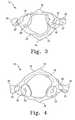
- FIG. 4is an inferior view of the C1 vertebra showing the pathways of FIG. 1 opening at the inferior articular facet.
- FIG. 5is an elevation view of the C2 vertebra showing one pathway portion between the lamina and the superior articular facet.
- FIG. 6is an elevation view of one embodiment stabilization device.
- FIG. 7is a disassembled view of another embodiment stabilization device.
- FIG. 8is a detailed section view of a leading end and a trailing end of the stabilization device of FIG. 7 when assembled.
- FIG. 9is a sectional view of one embodiment of a drill instrument.
- FIG. 10is an elevational view of a spinal column segment with an insertion instrument mounted thereto to facilitate pathway formation and stabilization device placement.
- FIG. 11is an elevational view of another embodiment stabilization device.
- FIG. 12is an elevational view of another embodiment stabilization device.
- FIG. 13is an elevational view of another embodiment stabilization device.
- Stabilization of adjacent vertebraeis provided with placement of a stabilization device through adjacent articular surfaces of bony structures, such as the cervical vertebrae and occiput, linking one or more of the vertebrae and/or occiput to one another.
- the stabilization deviceincludes a curved profile along its longitudinal axis to facilitate its placement along a pathway that includes a joint formed by adjacent articular surfaces while minimizing the invasiveness of the procedure required to accommodate placement of the stabilization device. Furthermore, placement of the stabilization device through the joint reduces moment loads on the stabilization device since the stabilization device is located along or adjacent to an axis of movement of the adjacent bony structures.
- Stabilizationcan be targeted to the vertebral level or levels desired while motion of the adjacent, non-instrumented vertebral level or levels can be preserved. Stabilization can be completed along one or more vertebral levels in the same surgical procedure with one stabilization device, or with multiple stabilization devices. It is further contemplated that multiple stabilization devices can be positioned to stabilize a particular vertebral level.
- a spinal column segment 10including the upper cervical vertebra C1 designated at 12 and the next lower cervical vertebra C2 designated at 30 .
- Occiput 50shown in FIG. 2 , resides at the superior end of C1 vertebra 12 .
- Occiput 50includes foramen magnum 52 and occipita condyles 54 on opposite sides of foramen magnum 52 .
- Occipita condyles 54are supported on and form a joint with respective ones of the superior articular facets 18 of C1 vertebra 12 , shown in further detail in FIG. 3 , a superior view, and in FIG. 4 , an inferior view.
- the skullcan articulate relative to C1 vertebra 12 about the joints formed between occipita condyles 54 and superior articular facets 18 .
- C1 vertebra 12includes posterior tubercle 14 and anterior tubercle 26 .
- Laminae 16extend from posterior tubercle 14 to respective lateral masses of the C1 vertebra 12 .
- C1 vertebra 12further includes transverse processes 20 and transverse foramen 22 .
- Inferior articular facets 24are supported on superior articular facets 44 of C2 vertebra 30 .
- C2 vertebra 30is further shown in FIG. 5 in a posterior view, and includes odontoid process 32 along an anterior portion thereof.
- Spinous process 38projects posteriorly from vertebra C2 and laminae 42 extend in opposite directions therefrom to lateral masses 40 .
- Lateral masses 40include a bony structure that forms superior articular facet 44 and inferior articular facet 46 , which is oriented anteriorly for engagement with the superior articular facet of the C3 vertebra (not shown.)
- a pair of insertion pathways for receiving stabilization devicesis shown in FIGS. 1-5 .
- a first insertion pathway 60is provided from C2 vertebra 30 , through C1 vertebra 12 , and into occiput 50 .
- a second insertion pathway 70is shown from C1 vertebra 12 to occiput 50 . It should be understood that surgical procedures are contemplated which employ identical insertion pathways 60 or 70 on each side of spinal column segment 10 and occiput 50 ; or a single insertion pathway 60 or 70 on one of the sides of spinal column segment 10 and occiput 50 . It is further contemplated that insertion pathway 60 can terminate at a blind end in C1 vertebra 12 to provide stabilization only for the C1-C2 vertebral level.
- Insertion pathways 60 , 70extend through the adjacent articulating surfaces of the facet joints to provide an avenue for insertion of a stabilization device. Insertion pathways 60 , 70 are curved to accommodate the proper positioning of the stabilization devices relative to the anatomy of spinal column segment 10 and occiput 50 , and to minimize the invasiveness of the procedure into the tissue in the approach to spinal column segment 10 for formation of pathways 60 , 70 .
- first insertion pathway 60includes an inferior opening 62 in lateral mass 40 of C2 vertebra 30 .
- Insertion pathway 60extends from opening 62 through the bony structure of C2 vertebra 30 , where it opens at the superior articular facet 44 of C2 vertebra 30 .
- Insertion pathway 60further extends through the facet joint into the inferior articular facet 24 of C1 vertebra 12 .
- Insertion pathway 60can terminate at a blind end in the lateral mass of C1vertebra 12 for a single level stabilization of the C1 and C2 vertebrae 12 , 30 .
- Insertion pathway 60can continue through the lateral mass of C1 vertebra 12 and through opening 64 at the superior articular facet 18 of C1 vertebra 12 . Insertion pathway 60 extends through the joint between C1 vertebra 12 and occiput 50 into the aligned receptacle 66 formed in occiput condyle 54 , where insertion pathway 60 terminates in a blind end.
- second insertion pathway 70includes an inferior opening 72 in lamina 16 of C1 vertebra 12 .
- Second insertion pathway 70extends from opening 72 through the bony structure of C1 vertebra 12 , where it opens at opening 74 in the superior articular facet 18 of C1 vertebra 12 .
- Insertion pathway 70extends through the joint between occiput 50 into the aligned receptacle 76 in occiput condyle 54 , where insertion pathway 70 terminates in a blind end.
- Stabilization device 100for insertion in a pathway 60 , 70 .
- Stabilization device 100includes a body 102 having a length extending along and curved along longitudinal axis 104 .
- Body 102extends between a leading end 106 and a trailing end 108 .
- the curvature of body 102 between ends 106 , 108can be defined by a radius R to facilitate insertion along a pathway defined by an arc A formed about radius R.
- stabilization device 100is a rod or shaft curved at a single radius R along arc A, and longitudinal axis 104 is co-linear with arc A.
- stabilization device 100can have a curvature that differs from arc A, or can have a curvature that varies or is compounded along its length.
- body 102can include a circular cross-sectional shape; however, other shapes are also contemplated, including oval, polygonal, square, rectangular, non-circular, and irregular cross-sections, for example.
- the cross-sectioncan be of uniform dimension along the length of body 102 , or can be tapered, stepped or otherwise varied to provide regions of greater and lesser dimension.
- Body 102can be sized with a cross-section along at least a portion of the length thereof that is slightly greater than size of pathway 60 , 70 to provide frictional engagement with the surrounding bony tissue.
- Body 102can also be provided with a cross-sectional size that is about the same or less than the opening formed by pathway 60 , 70 .
- body 102can be provided with a cross-section, such as a non-circular cross-sectional shape, that differs from the shape of the opening formed by pathway 60 , 70 .
- Body 102can include surface features extending along body 102 and/or transversely to longitudinal axis 104 that enhance engagement of body 102 with the adjacent bony tissue. Examples of surface features include knurlings, teeth, barbs, spikes, ridges, and/or grooves.
- Stabilization device 100can be rigid or semi-rigid, at least during placement, to facilitate placement through the pathways 60 , 70 by pushing on the trailing end thereof to advance the leading end.
- body 102is flexible and is mounted to a carrier for insertion through pathways 60 , 70 .
- Body 102can be solid, or can include any one or combination of fenestrations, dimples, longitudinal passages, transverse passages, and through-holes.
- Body 102can be comprised of a metal or metal alloy, such as stainless steel, titanium, or other suitable biocompatible metal material.
- stabilization devicecan be an elastic or super-elastic member made from a super-elastic metal alloy, such as nitinol, or a polymer material.
- Stabilization device 100can be in the form of a cable, band or artificial ligament made from any suitable bio-compatible material, and employed to tether the bony structures to one another through pathways 60 , 70 .
- body 102can be comprised entirely or partially of resorbable material, or of porous material, to facilitate integration with the bony tissue surrounding body 102 .
- body 102can be comprised of ceramic material, or bone material, for example.
- Body 102can be coated, impregnated, or otherwise be a carrier for bone growth promoting material and/or therapeutic substances to promote or provide bone growth and healing.
- body 102is formed by placing a material in a first form in the formed pathway 60 , 70 , and then allowing the material to cure in situ to form a stabilization device.
- FIG. 7there is shown another embodiment stabilization device 120 , which can include any of the features and forms discussed above with respect to stabilization device 100 .
- Stabilization device 120includes an outer member 122 and an inner member 150 .
- Outer member 122includes a passage 130 extending along a longitudinal axis 124 thereof.
- Outer member 122includes a leading insertion end 126 and an opposite trailing end 128 .
- Passage 130opens at trailing end 128 , and at least extends adjacent to leading end 126 . In the illustrated embodiment, passage 130 opens at leading end 126 .
- Inner member 150includes an elongated body 152 extending between a leading end nose 156 and an intermediate nose 162 along longitudinal axis 154 .
- An enlarged trailing end portion 160extends from intermediate nose 162 .
- Intermediate nose 162includes a tapered surface profile that transitions between enlarged trailing end portion 160 and body 152 .
- a thread pattern 164is formed along a portion of the length of body 152 adjacent intermediate nose 162 .
- Leading end nose 156includes an enlarged configuration relative to body 152 , and includes tapered surfaces 158 extending therefrom toward the tip of inner member 150 .
- inner member 150is positioned in passage 130 of outer member 122 .
- Outer member 122can include thread pattern 144 along an inner wall surface thereof configured to threadingly engage thread pattern 164 of inner member 150 , although non-threaded engagement between inner member 122 and outer member 150 is also contemplated.
- leading end nose 156is positioned adjacent to leading end 126 of outer member 122 such that nose 156 is received in passage 130 adjacent a tapered leading end portion 133 thereof.
- enlarged trailing end portion 160is received in an enlarged trailing end portion 131 of passage 130 .
- stabilization device 120includes a reduced profile along the length thereof to facilitate insertion into pathways 60 , 70 .
- inner member 150can be advanced in outer member 122 such that leading end nose 156 contacts tapered inner surface portion 148 of outer member 122 along leading end portion 133 of passage 130 as shown in dashed lines in FIG. 8 .
- Leading end portion 126includes a slot or relief 136 that provides at least two fingers 132 , 134 .
- Leading end nose 156provides a wedge-effect and pushes on inner surface portion 148 to bias fingers 132 , 134 away from one another and to deploy end nose 156 into firm engagement with the adjacent bony tissue of the pathway 60 , 70 into which stabilization device 120 has been positioned.
- trailing end 128 of outer member 122includes a slot or relief 142 that provides at least two fingers 138 , 140 adjacent trailing end portion 128 .
- the tapered surface of intermediate nose 162contacts and pushes on intermediate tapered portion 146 of passage 130 , providing a wedge effect that pushes fingers 138 , 140 away from one another as shown in dashed lines in FIG. 8 .
- Trailing end 128is then deployed into engagement with the adjacent bony tissue of the pathways 60 , 70 into which stabilization device 120 has been positioned.
- inner member 150can be configured to move longitudinally within outer member 122 to deploy one or more portions of it into engagement with the adjacent bony tissue.
- inner member 150can interface with outer member 150 via a snap fit, interference fit or other suitable coupling arrangement permitting longitudinal reciprocal movement of inner member 150 relative to outer member 122 .
- stabilization device 250including a curved body 252 and a leading end 254 .
- Leading insertion end 254includes a threaded nose configuration for engaging the adjacent bony tissue.
- Body 252is sufficiently flexible and sized to permit rotation of body 252 to rotate leading insertion end 254 .
- body 252includes a central passage opening to leading insertion end 254 .
- Leading insertion end 254is rotatably coupled to body 252 .
- a flexible drivercan be positioned through the passage.
- a stabilization device 270in another embodiment shown in FIG. 12 , includes a curved body 272 extending between a leading insertion end 274 and a trailing end 276 .
- Each of the ends 274 , 276is provided with a threaded nose arrangement for engagement with the adjacent bony tissue.
- the pitch of the nose threadscan be the same at each end, or can be different to provide either a distraction or compression effect as the threaded noses are engaged with the adjacent bony structure.
- a central lumen or passagecan be provided through body 272 to leading insertion end 274 to receive a driver instrument.
- Body 272can also be flexible between ends 274 , 276 and sized to permit rotation of body 252 to rotate leading insertion end 254 .
- FIG. 13another embodiment stabilization device 290 is provided that includes a curved body 292 and a threaded leading insertion end 294 .
- the trailing end 296includes an enlarged contact member 298 projecting therefrom.
- Contact member 298engages the bone about the entrance to the pathway formed therein when body 292 and insertion end 294 are positioned in the pathway. As insertion end 294 is threadingly engaged in the pathway, contact member 298 engages the bone to deliver a compression force between the adjacent bony structures along the pathway.
- FIG. 9there is shown a cutting instrument 160 which includes an outer shaft 162 defining a passage 164 therethrough.
- a cutting head 170is located adjacent a leading end 166 of outer shaft 162
- a coupler 172is located adjacent to a trailing end 168 of outer shaft 162 .
- a flexible drive member 174extends between and interconnects coupler 172 with cutting head 170 .
- a rotary power source(not shown) can be engaged to coupler 172 , and operated to deliver a rotary force thereto. Rotation of coupler 172 is transmitted through drive member 174 to rotate cutting head 170 .
- Cutting head 170can be configured to drill or ream a pathway through bony material along the desired insertion path.
- Outer shaft 162is curved along its longitudinal axis to conform to the desired shape of the pathway 60 , 70 to be formed therewith.
- Cutting head 170removes bone material from the pathway 60 , 70 which can deposited in passage 164 for evacuation.
- Drill instrument 160can be guided through the bony structures to form pathway 60 , 70 with image guidance technology employed during the surgical procedure.
- the pathway 60 , 70can further be defined through pre-operative X-rays or fluoroscopy to determine the appropriate location and trajectory for pathways 60 , 70 prior to the surgical stabilization procedure.
- Outer shaft 162can be bent, formed, controlled or manipulated so that the pathway of the desired shape, trajectory and length is formed.
- drive member 174includes a central guide lumen 176 extending therethrough.
- Guide lumen 176extends through cutting head 170 and also coupler 172 .
- Guide lumen 176can receive a guidewire or other device along which the cannulated drilling or reaming instrument 160 is to be moved to form the pathway along the desired trajectory.
- the stabilization devicecan be inserted into the pathway with freehand techniques or instruments, or with instruments that provide for controlled insertion.
- FIG. 10shows C1 vertebra 12 and C2 vertebra 30 in section along pathway 60 .
- occiput 50is not shown, it should be understood that, as discussed above, pathway 60 may extend into occiput 50 .
- the discussion that followsalso has application with pathway 70 .
- C1 vertebra 12 and C2 vertebra 30each include an anchor 222 , 232 , respectively, engaged thereto.
- a first anchor extension 220extends from first anchor 222
- a second anchor extension 230extends from second anchor 232 .
- An insertion instrument 200can be provided that is, in one embodiment, configured substantially as described in U.S. Pat. No. 6,530,929, which is hereby incorporated by reference in its entirety.
- Insertion instrument 200includes a first portion 202 pivotally mounted to the anchor extensions 220 , 230 about pivot axis 206 .
- Insertion instrument 200further includes a second portion 204 extending from and transversely oriented to first portion 202 .
- First portion 202is rotatable about the proximal ends of anchor extensions 220 , 230 to swing second portion 204 along an arcuate axis 210 .
- First portion 202includes a length extending from pivot axis 206 that corresponds to the radius or other shape required from pivot axis 206 to form pathways 60 , 70 through the bony structures. Accordingly, the length of first portion 202 is sufficient to position second portion 204 and thus the stabilization device coupled thereto adjacent or below anchors 222 , 232 and into the bony structure to which insertion instrument 200 is mounted.
- a stabilization device, drill instrument, guidewire or other devicecan be delivered to the bony structure along the desired pathway.
- stabilization device 100is releasably coupled to and extends from second portion 204 .
- longitudinal axis 104 of stabilization device 100extends along arcuate axis 210 . Accordingly, as first portion 202 is pivoted about pivot axis 206 , second portion 204 and thus stabilization device 100 are moved along arcuate axis 210 .
- insertion instrument 200can be mounted to a single anchor engaged to the bony structure, or to more than two anchors.
- Suitable anchorsinclude multi-axial screws, uni-axial screws, staples, tacks, stakes, pins, wires, posts or other device capable of suitably mounting the insertion instrument 200 to a bony structure.
- pathways 60 , 70are formed by positioning a guidewire through the bony structure along the desired pathway trajectory through the bony tissue.
- the guidewire insertion and positioningcan be monitored via a surgical navigation system employing fluoroscopy or other suitable viewing instrumentation.
- the guidewirecan be coupled to an inserter, such as insertion instrument 200 , to facilitate positioning along the pathway 60 , 70 .
- a cutter or drill with a flexible shaftcan be guided along the guidewire to form pathway 60 , 70 .
- drill instrument 160can be provided with guide lumen 176 therealong to receive the guidewire as it is advanced along pathway 60 , 70 .
- Other embodimentscontemplate a drill instrument with a central lumen for receiving the guidewire as the curved drill instrument is advanced therealong.
- Drill instrument 160can be coupled to such an inserter device to provide image guided navigation of the drill instrument along the pathways 60 , 70 .
- the stabilization devicecan further be coupled to such an inserter device and inserted into the pathway 60 , 70 to provided image-guided navigation and monitoring of the stabilization device insertion.
Landscapes
- Health & Medical Sciences (AREA)
- Orthopedic Medicine & Surgery (AREA)
- Life Sciences & Earth Sciences (AREA)
- Neurology (AREA)
- Surgery (AREA)
- Heart & Thoracic Surgery (AREA)
- Engineering & Computer Science (AREA)
- Biomedical Technology (AREA)
- Nuclear Medicine, Radiotherapy & Molecular Imaging (AREA)
- Medical Informatics (AREA)
- Molecular Biology (AREA)
- Animal Behavior & Ethology (AREA)
- General Health & Medical Sciences (AREA)
- Public Health (AREA)
- Veterinary Medicine (AREA)
- Surgical Instruments (AREA)
Abstract
Description
Claims (30)
Priority Applications (2)
| Application Number | Priority Date | Filing Date | Title |
|---|---|---|---|
| US10/795,880US7799053B2 (en) | 2004-03-08 | 2004-03-08 | Occipital and cervical stabilization systems and methods |
| PCT/US2005/007314WO2005087122A1 (en) | 2004-03-08 | 2005-03-07 | Occipital and cervical stabilization systems and methods |
Applications Claiming Priority (1)
| Application Number | Priority Date | Filing Date | Title |
|---|---|---|---|
| US10/795,880US7799053B2 (en) | 2004-03-08 | 2004-03-08 | Occipital and cervical stabilization systems and methods |
Publications (2)
| Publication Number | Publication Date |
|---|---|
| US20050197660A1 US20050197660A1 (en) | 2005-09-08 |
| US7799053B2true US7799053B2 (en) | 2010-09-21 |
Family
ID=34912538
Family Applications (1)
| Application Number | Title | Priority Date | Filing Date |
|---|---|---|---|
| US10/795,880Expired - LifetimeUS7799053B2 (en) | 2004-03-08 | 2004-03-08 | Occipital and cervical stabilization systems and methods |
Country Status (2)
| Country | Link |
|---|---|
| US (1) | US7799053B2 (en) |
| WO (1) | WO2005087122A1 (en) |
Cited By (56)
| Publication number | Priority date | Publication date | Assignee | Title |
|---|---|---|---|---|
| US20060129153A1 (en)* | 2003-04-10 | 2006-06-15 | Kaj Klaue | Device for temporarily splinting toes |
| US20100160967A1 (en)* | 2008-12-22 | 2010-06-24 | Joseph Capozzoli | Variable tension spine fixation rod |
| US8088163B1 (en) | 2008-02-06 | 2012-01-03 | Kleiner Jeffrey B | Tools and methods for spinal fusion |
| US20120046695A9 (en)* | 2004-06-10 | 2012-02-23 | Spinal Elements, Inc. | Implant and method for facet immobilization |
| USD656610S1 (en) | 2009-02-06 | 2012-03-27 | Kleiner Jeffrey B | Spinal distraction instrument |
| US8257439B2 (en) | 2004-12-22 | 2012-09-04 | Ldr Medical | Intervertebral disc prosthesis |
| US8267999B2 (en) | 2002-11-05 | 2012-09-18 | Ldr Medical | Intervertebral disc prosthesis |
| US8343219B2 (en) | 2007-06-08 | 2013-01-01 | Ldr Medical | Intersomatic cage, intervertebral prosthesis, anchoring device and implantation instruments |
| US8366748B2 (en) | 2008-12-05 | 2013-02-05 | Kleiner Jeffrey | Apparatus and method of spinal implant and fusion |
| US8465546B2 (en) | 2007-02-16 | 2013-06-18 | Ldr Medical | Intervertebral disc prosthesis insertion assemblies |
| US8685031B2 (en) | 2009-09-18 | 2014-04-01 | Spinal Surgical Strategies, Llc | Bone graft delivery system |
| US8771284B2 (en) | 2005-11-30 | 2014-07-08 | Ldr Medical | Intervertebral disc prosthesis and instrumentation for insertion of the prosthesis between the vertebrae |
| US8858635B2 (en) | 2004-02-04 | 2014-10-14 | Ldr Medical | Intervertebral disc prosthesis |
| US8864654B2 (en) | 2010-04-20 | 2014-10-21 | Jeffrey B. Kleiner | Method and apparatus for performing retro peritoneal dissection |
| US8906028B2 (en) | 2009-09-18 | 2014-12-09 | Spinal Surgical Strategies, Llc | Bone graft delivery device and method of using the same |
| USD723682S1 (en) | 2013-05-03 | 2015-03-03 | Spinal Surgical Strategies, Llc | Bone graft delivery tool |
| US8974532B2 (en) | 2004-04-28 | 2015-03-10 | Ldr Medical | Intervertebral disc prosthesis |
| US8979932B2 (en) | 2005-09-23 | 2015-03-17 | Ldr Medical | Intervertebral disc prosthesis |
| US9039774B2 (en) | 2012-02-24 | 2015-05-26 | Ldr Medical | Anchoring device and system for an intervertebral implant, intervertebral implant and implantation instrument |
| US9044337B2 (en) | 2009-12-31 | 2015-06-02 | Ldr Medical | Anchoring device and system for an intervertebral implant, intervertebral implant and implantation instrument |
| US9060877B2 (en) | 2009-09-18 | 2015-06-23 | Spinal Surgical Strategies, Llc | Fusion cage with combined biological delivery system |
| US9078765B2 (en) | 2001-07-13 | 2015-07-14 | Ldr Medical | Vertebral cage device with modular fixation |
| US9173694B2 (en) | 2009-09-18 | 2015-11-03 | Spinal Surgical Strategies, Llc | Fusion cage with combined biological delivery system |
| US9186193B2 (en) | 2009-09-18 | 2015-11-17 | Spinal Surgical Strategies, Llc | Fusion cage with combined biological delivery system |
| US9247943B1 (en) | 2009-02-06 | 2016-02-02 | Kleiner Intellectual Property, Llc | Devices and methods for preparing an intervertebral workspace |
| USD750249S1 (en) | 2014-10-20 | 2016-02-23 | Spinal Surgical Strategies, Llc | Expandable fusion cage |
| US9333095B2 (en) | 2001-05-04 | 2016-05-10 | Ldr Medical | Intervertebral disc prosthesis, surgical methods, and fitting tools |
| US9463091B2 (en) | 2009-09-17 | 2016-10-11 | Ldr Medical | Intervertebral implant having extendable bone fixation members |
| US20170056633A1 (en)* | 2012-01-13 | 2017-03-02 | Teleflex Medical Incorporated | Bumped dilator tip |
| US20170079699A1 (en)* | 2015-07-13 | 2017-03-23 | IntraFuse, LLC | Flexible bone implant |
| US9629729B2 (en) | 2009-09-18 | 2017-04-25 | Spinal Surgical Strategies, Llc | Biological delivery system with adaptable fusion cage interface |
| US9675389B2 (en) | 2009-12-07 | 2017-06-13 | Samy Abdou | Devices and methods for minimally invasive spinal stabilization and instrumentation |
| US9713535B2 (en) | 2006-02-15 | 2017-07-25 | Ldr Medical | Transforaminal intersomatic cage for an intervertebral fusion graft and an instrument for implanting the cage |
| US9717403B2 (en) | 2008-12-05 | 2017-08-01 | Jeffrey B. Kleiner | Method and apparatus for performing retro peritoneal dissection |
| USD797290S1 (en) | 2015-10-19 | 2017-09-12 | Spinal Surgical Strategies, Llc | Bone graft delivery tool |
| US9877842B2 (en) | 2014-01-30 | 2018-01-30 | Ldr Medical | Anchoring device for a spinal implant, spinal implant and implantation instrumentation |
| US9937050B2 (en) | 2013-05-16 | 2018-04-10 | Ldr Medical | Vertebral implant, vertebral fastening device of the implant and implant instrumentation |
| US10154863B2 (en) | 2015-07-13 | 2018-12-18 | IntraFuse, LLC | Flexible bone screw |
| US10245159B1 (en) | 2009-09-18 | 2019-04-02 | Spinal Surgical Strategies, Llc | Bone graft delivery system and method for using same |
| USD853560S1 (en) | 2008-10-09 | 2019-07-09 | Nuvasive, Inc. | Spinal implant insertion device |
| US10478310B2 (en) | 2014-05-06 | 2019-11-19 | Ldr Medical, S.A.S. | Vertebral implant, device for vertebral attachment of the implant and instrumentation for implantation thereof |
| US10485595B2 (en) | 2015-07-13 | 2019-11-26 | IntraFuse, LLC | Flexible bone screw |
| US10499960B2 (en) | 2015-07-13 | 2019-12-10 | IntraFuse, LLC | Method of bone fixation |
| US10548740B1 (en) | 2016-10-25 | 2020-02-04 | Samy Abdou | Devices and methods for vertebral bone realignment |
| US10575961B1 (en) | 2011-09-23 | 2020-03-03 | Samy Abdou | Spinal fixation devices and methods of use |
| US10603185B2 (en) | 2004-02-04 | 2020-03-31 | Ldr Medical | Intervertebral disc prosthesis |
| US10695105B2 (en) | 2012-08-28 | 2020-06-30 | Samy Abdou | Spinal fixation devices and methods of use |
| US10857003B1 (en) | 2015-10-14 | 2020-12-08 | Samy Abdou | Devices and methods for vertebral stabilization |
| US10918498B2 (en) | 2004-11-24 | 2021-02-16 | Samy Abdou | Devices and methods for inter-vertebral orthopedic device placement |
| US10973648B1 (en) | 2016-10-25 | 2021-04-13 | Samy Abdou | Devices and methods for vertebral bone realignment |
| US10973656B2 (en) | 2009-09-18 | 2021-04-13 | Spinal Surgical Strategies, Inc. | Bone graft delivery system and method for using same |
| US11006982B2 (en) | 2012-02-22 | 2021-05-18 | Samy Abdou | Spinous process fixation devices and methods of use |
| US11173040B2 (en) | 2012-10-22 | 2021-11-16 | Cogent Spine, LLC | Devices and methods for spinal stabilization and instrumentation |
| US11179248B2 (en) | 2018-10-02 | 2021-11-23 | Samy Abdou | Devices and methods for spinal implantation |
| US11666455B2 (en) | 2009-09-18 | 2023-06-06 | Spinal Surgical Strategies, Inc., A Nevada Corporation | Bone graft delivery devices, systems and kits |
| US12279972B2 (en) | 2008-05-22 | 2025-04-22 | Spinal Surgical Strategies, Inc. | Spinal fusion cage system with inserter |
Families Citing this family (33)
| Publication number | Priority date | Publication date | Assignee | Title |
|---|---|---|---|---|
| US7815665B2 (en)* | 2003-09-24 | 2010-10-19 | N Spine, Inc. | Adjustable spinal stabilization system |
| US7137985B2 (en) | 2003-09-24 | 2006-11-21 | N Spine, Inc. | Marking and guidance method and system for flexible fixation of a spine |
| US8979900B2 (en) | 2003-09-24 | 2015-03-17 | DePuy Synthes Products, LLC | Spinal stabilization device |
| US7641690B2 (en)* | 2004-08-23 | 2010-01-05 | Abdou M Samy | Bone fixation and fusion device |
| WO2006041963A2 (en) | 2004-10-05 | 2006-04-20 | Abdou M S | Devices and methods for inter-vertebral orthopedic device placement |
| US8870920B2 (en) | 2005-10-07 | 2014-10-28 | M. Samy Abdou | Devices and methods for inter-vertebral orthopedic device placement |
| WO2008097216A2 (en)* | 2006-02-02 | 2008-08-14 | Trinity Orthopedics | Percutaneous facet joint fusion system and method |
| US8303630B2 (en) | 2006-07-27 | 2012-11-06 | Samy Abdou | Devices and methods for the minimally invasive treatment of spinal stenosis |
| US7931676B2 (en)* | 2007-01-18 | 2011-04-26 | Warsaw Orthopedic, Inc. | Vertebral stabilizer |
| US8133261B2 (en) | 2007-02-26 | 2012-03-13 | Depuy Spine, Inc. | Intra-facet fixation device and method of use |
| WO2008128067A2 (en)* | 2007-04-11 | 2008-10-23 | Eduardo Gonzalez-Hernandez | Curved assembly for reattachment of fragmented bone segments |
| US8894685B2 (en)* | 2007-04-13 | 2014-11-25 | DePuy Synthes Products, LLC | Facet fixation and fusion screw and washer assembly and method of use |
| US8043334B2 (en) | 2007-04-13 | 2011-10-25 | Depuy Spine, Inc. | Articulating facet fusion screw |
| US8197513B2 (en)* | 2007-04-13 | 2012-06-12 | Depuy Spine, Inc. | Facet fixation and fusion wedge and method of use |
| US20090216273A1 (en)* | 2008-02-19 | 2009-08-27 | U. S. Spinal Technologies, L.L.C. | Curved facet joint fixation assembly and associated implantation tool and method |
| WO2009131955A1 (en)* | 2008-04-21 | 2009-10-29 | Total Connect Spine, Llc | Posterior spinal fastener and method for using same |
| US9357985B2 (en)* | 2008-05-15 | 2016-06-07 | Spinal Elements, Inc. | Method for accessing a spinal facet joint |
| US8951289B2 (en)* | 2008-10-09 | 2015-02-10 | Total Connect Spine, Llc | Spinal connection assembly |
| US8506567B2 (en) | 2009-02-04 | 2013-08-13 | Lanx, Inc. | Occipital plate fixation system |
| US8795335B1 (en) | 2009-11-06 | 2014-08-05 | Samy Abdou | Spinal fixation devices and methods of use |
| US9089372B2 (en) | 2010-07-12 | 2015-07-28 | DePuy Synthes Products, Inc. | Pedicular facet fusion screw with plate |
| US8828059B2 (en) | 2011-04-25 | 2014-09-09 | Warsaw Orthopedic, Inc. | Elongated connecting elements for minimally invasive surgical procedures |
| US20120277798A1 (en)* | 2011-04-28 | 2012-11-01 | Warsaw Orthopedic, Inc. | Spinal Rod Construct to Limit Facet Impingement |
| US10799367B2 (en) | 2011-10-05 | 2020-10-13 | H. Lee Moffitt Cancer Center And Research Institute, Inc. | Bone fusion system |
| WO2013052807A2 (en) | 2011-10-05 | 2013-04-11 | H. Lee Moffitt Cancer Center And Research Institute, Inc. | Bone fusion system |
| US20130317557A1 (en)* | 2012-05-26 | 2013-11-28 | Custom Spine, Inc. | Mis rod insertion device and method |
| WO2015095353A1 (en)* | 2013-12-17 | 2015-06-25 | H. Lee Moffit Cancer Center And Research Institute, Inc. | Transdiscal screw |
| EP2886074B1 (en)* | 2013-12-20 | 2016-09-14 | Biedermann Technologies GmbH & Co. KG | Rod insertion device |
| US10322009B2 (en) | 2014-08-01 | 2019-06-18 | H. Lee Moffitt Cancer Center And Research Institute, Inc. | Expandable intervertebral cage |
| US10478238B2 (en) | 2014-12-02 | 2019-11-19 | Activortho, Inc. | Active compression devices, methods of assembly and methods of use |
| CA3015902A1 (en) | 2016-02-26 | 2017-08-31 | Activortho, Inc. | Active compression apparatus, methods of assembly and methods of use |
| US11224467B2 (en) | 2016-02-26 | 2022-01-18 | Activortho, Inc. | Active compression apparatus, methods of assembly and methods of use |
| US11890033B1 (en)* | 2022-10-28 | 2024-02-06 | Warsaw Orthopedic, Inc. | Spinal implant system and method |
Citations (31)
| Publication number | Priority date | Publication date | Assignee | Title |
|---|---|---|---|---|
| US2381050A (en)* | 1943-12-04 | 1945-08-07 | Mervyn G Hardinge | Fracture reducing device |
| US2490364A (en)* | 1948-02-27 | 1949-12-06 | Herman H Livingston | Bone pin |
| US2699774A (en)* | 1952-05-12 | 1955-01-18 | Livingston Herman Harrison | Bone pin locking device |
| US3678925A (en)* | 1969-10-03 | 1972-07-25 | Artur Fischer | Connector for fractured bones |
| US3716051A (en)* | 1970-09-10 | 1973-02-13 | Fischer Artur | Expandible connector for fractured bones |
| US3760802A (en)* | 1971-02-26 | 1973-09-25 | Fischer Artur | Supporting device for fractured tubular bones |
| US3805775A (en) | 1970-09-18 | 1974-04-23 | Fischer Artur | Expanding bone connector |
| US4541423A (en) | 1983-01-17 | 1985-09-17 | Barber Forest C | Drilling a curved hole |
| US4790303A (en) | 1987-03-11 | 1988-12-13 | Acromed Corporation | Apparatus and method for securing bone graft |
| US4854312A (en)* | 1988-04-13 | 1989-08-08 | The University Of Toledo | Expanding intramedullary nail |
| US5269785A (en) | 1990-06-28 | 1993-12-14 | Bonutti Peter M | Apparatus and method for tissue removal |
| US5489284A (en) | 1994-07-15 | 1996-02-06 | Smith & Nephew Richards Inc. | Cannulated modular intramedullary nail |
| US5545164A (en) | 1992-12-28 | 1996-08-13 | Advanced Spine Fixation Systems, Incorporated | Occipital clamp assembly for cervical spine rod fixation |
| US5591235A (en) | 1995-03-15 | 1997-01-07 | Kuslich; Stephen D. | Spinal fixation device |
| US5855579A (en) | 1994-07-15 | 1999-01-05 | Smith & Nephew, Inc. | Cannulated modular intramedullary nail |
| US5908423A (en) | 1993-05-27 | 1999-06-01 | Howmedica, Inc. | Flexible medullary reaming system |
| US6056749A (en) | 1999-03-15 | 2000-05-02 | Spineology, Inc. | Method and device for fixing and correcting spondylolisthesis anteriorly |
| WO2000067651A1 (en) | 1999-05-10 | 2000-11-16 | Highgate Orthopedics, Inc. | Systems and methods for spinal fixation |
| US6226548B1 (en) | 1997-09-24 | 2001-05-01 | Surgical Navigation Technologies, Inc. | Percutaneous registration apparatus and method for use in computer-assisted surgical navigation |
| US6287313B1 (en) | 1999-11-23 | 2001-09-11 | Sdgi Holdings, Inc. | Screw delivery system and method |
| US6419678B1 (en) | 2000-11-28 | 2002-07-16 | Wilson T. Asfora | Curved drill guide system |
| US6436119B1 (en) | 1999-09-30 | 2002-08-20 | Raymedica, Inc. | Adjustable surgical dilator |
| US20020120270A1 (en) | 2001-02-28 | 2002-08-29 | Hai Trieu | Flexible systems for spinal stabilization and fixation |
| US20020161368A1 (en)* | 1999-10-20 | 2002-10-31 | Foley Kevin T. | Instruments and methods for stabilization of bony structures |
| US20020165544A1 (en) | 1999-11-11 | 2002-11-07 | Stephan Perren | Radially expandable intramedullary nail |
| US6498421B1 (en) | 2001-06-15 | 2002-12-24 | Amega Lab, L.L.C. | Ultrasonic drilling device with arc-shaped probe |
| US20030158557A1 (en) | 2000-02-16 | 2003-08-21 | Cragg Andrew H. | Method and apparatus for spinal distraction and fusion |
| US20030204189A1 (en) | 2000-02-16 | 2003-10-30 | Cragg Andrew H. | Axial spinal implant and method and apparatus for implanting an axial spinal implant within the vertebrae of the spine |
| US20060009767A1 (en) | 2004-07-02 | 2006-01-12 | Kiester P D | Expandable rod system to treat scoliosis and method of using the same |
| US20060036259A1 (en) | 2004-08-03 | 2006-02-16 | Carl Allen L | Spine treatment devices and methods |
| US20070191846A1 (en) | 2006-01-31 | 2007-08-16 | Aurelien Bruneau | Expandable spinal rods and methods of use |
Family Cites Families (2)
| Publication number | Priority date | Publication date | Assignee | Title |
|---|---|---|---|---|
| FR2644286A1 (en)* | 1989-03-07 | 1990-09-14 | Thomson Tubes Electroniques | ELECTRON BEAM GENERATOR AND ELECTRONIC DEVICES USING SUCH A GENERATOR |
| JP4123405B2 (en)* | 2001-01-16 | 2008-07-23 | 富士フイルム株式会社 | Button update method for client / server system and client application |
- 2004
- 2004-03-08USUS10/795,880patent/US7799053B2/ennot_activeExpired - Lifetime
- 2005
- 2005-03-07WOPCT/US2005/007314patent/WO2005087122A1/enactiveApplication Filing
Patent Citations (34)
| Publication number | Priority date | Publication date | Assignee | Title |
|---|---|---|---|---|
| US2381050A (en)* | 1943-12-04 | 1945-08-07 | Mervyn G Hardinge | Fracture reducing device |
| US2490364A (en)* | 1948-02-27 | 1949-12-06 | Herman H Livingston | Bone pin |
| US2699774A (en)* | 1952-05-12 | 1955-01-18 | Livingston Herman Harrison | Bone pin locking device |
| US3678925A (en)* | 1969-10-03 | 1972-07-25 | Artur Fischer | Connector for fractured bones |
| US3716051A (en)* | 1970-09-10 | 1973-02-13 | Fischer Artur | Expandible connector for fractured bones |
| US3805775A (en) | 1970-09-18 | 1974-04-23 | Fischer Artur | Expanding bone connector |
| US3760802A (en)* | 1971-02-26 | 1973-09-25 | Fischer Artur | Supporting device for fractured tubular bones |
| US4541423A (en) | 1983-01-17 | 1985-09-17 | Barber Forest C | Drilling a curved hole |
| US4790303A (en) | 1987-03-11 | 1988-12-13 | Acromed Corporation | Apparatus and method for securing bone graft |
| US4854312A (en)* | 1988-04-13 | 1989-08-08 | The University Of Toledo | Expanding intramedullary nail |
| US5269785A (en) | 1990-06-28 | 1993-12-14 | Bonutti Peter M | Apparatus and method for tissue removal |
| US5545164A (en) | 1992-12-28 | 1996-08-13 | Advanced Spine Fixation Systems, Incorporated | Occipital clamp assembly for cervical spine rod fixation |
| US5908423A (en) | 1993-05-27 | 1999-06-01 | Howmedica, Inc. | Flexible medullary reaming system |
| US5489284A (en) | 1994-07-15 | 1996-02-06 | Smith & Nephew Richards Inc. | Cannulated modular intramedullary nail |
| US5855579A (en) | 1994-07-15 | 1999-01-05 | Smith & Nephew, Inc. | Cannulated modular intramedullary nail |
| US5591235A (en) | 1995-03-15 | 1997-01-07 | Kuslich; Stephen D. | Spinal fixation device |
| US6226548B1 (en) | 1997-09-24 | 2001-05-01 | Surgical Navigation Technologies, Inc. | Percutaneous registration apparatus and method for use in computer-assisted surgical navigation |
| US6056749A (en) | 1999-03-15 | 2000-05-02 | Spineology, Inc. | Method and device for fixing and correcting spondylolisthesis anteriorly |
| WO2000067651A1 (en) | 1999-05-10 | 2000-11-16 | Highgate Orthopedics, Inc. | Systems and methods for spinal fixation |
| US6607530B1 (en) | 1999-05-10 | 2003-08-19 | Highgate Orthopedics, Inc. | Systems and methods for spinal fixation |
| US6436119B1 (en) | 1999-09-30 | 2002-08-20 | Raymedica, Inc. | Adjustable surgical dilator |
| US6530929B1 (en) | 1999-10-20 | 2003-03-11 | Sdgi Holdings, Inc. | Instruments for stabilization of bony structures |
| US20020161368A1 (en)* | 1999-10-20 | 2002-10-31 | Foley Kevin T. | Instruments and methods for stabilization of bony structures |
| US20020165544A1 (en) | 1999-11-11 | 2002-11-07 | Stephan Perren | Radially expandable intramedullary nail |
| US6287313B1 (en) | 1999-11-23 | 2001-09-11 | Sdgi Holdings, Inc. | Screw delivery system and method |
| US20010027320A1 (en) | 1999-11-23 | 2001-10-04 | Rick Sasso | Screw delivery system and method |
| US20030204189A1 (en) | 2000-02-16 | 2003-10-30 | Cragg Andrew H. | Axial spinal implant and method and apparatus for implanting an axial spinal implant within the vertebrae of the spine |
| US20030158557A1 (en) | 2000-02-16 | 2003-08-21 | Cragg Andrew H. | Method and apparatus for spinal distraction and fusion |
| US6419678B1 (en) | 2000-11-28 | 2002-07-16 | Wilson T. Asfora | Curved drill guide system |
| US20020120270A1 (en) | 2001-02-28 | 2002-08-29 | Hai Trieu | Flexible systems for spinal stabilization and fixation |
| US6498421B1 (en) | 2001-06-15 | 2002-12-24 | Amega Lab, L.L.C. | Ultrasonic drilling device with arc-shaped probe |
| US20060009767A1 (en) | 2004-07-02 | 2006-01-12 | Kiester P D | Expandable rod system to treat scoliosis and method of using the same |
| US20060036259A1 (en) | 2004-08-03 | 2006-02-16 | Carl Allen L | Spine treatment devices and methods |
| US20070191846A1 (en) | 2006-01-31 | 2007-08-16 | Aurelien Bruneau | Expandable spinal rods and methods of use |
Cited By (123)
| Publication number | Priority date | Publication date | Assignee | Title |
|---|---|---|---|---|
| US9333095B2 (en) | 2001-05-04 | 2016-05-10 | Ldr Medical | Intervertebral disc prosthesis, surgical methods, and fitting tools |
| US9078765B2 (en) | 2001-07-13 | 2015-07-14 | Ldr Medical | Vertebral cage device with modular fixation |
| US8267999B2 (en) | 2002-11-05 | 2012-09-18 | Ldr Medical | Intervertebral disc prosthesis |
| US8672986B2 (en)* | 2003-04-10 | 2014-03-18 | DePuy Synthes Products, LLC | Device for temporarily splinting toes |
| US20060129153A1 (en)* | 2003-04-10 | 2006-06-15 | Kaj Klaue | Device for temporarily splinting toes |
| US10603185B2 (en) | 2004-02-04 | 2020-03-31 | Ldr Medical | Intervertebral disc prosthesis |
| US11957598B2 (en) | 2004-02-04 | 2024-04-16 | Ldr Medical | Intervertebral disc prosthesis |
| US8858635B2 (en) | 2004-02-04 | 2014-10-14 | Ldr Medical | Intervertebral disc prosthesis |
| US8974532B2 (en) | 2004-04-28 | 2015-03-10 | Ldr Medical | Intervertebral disc prosthesis |
| US9931142B2 (en)* | 2004-06-10 | 2018-04-03 | Spinal Elements, Inc. | Implant and method for facet immobilization |
| US20120046695A9 (en)* | 2004-06-10 | 2012-02-23 | Spinal Elements, Inc. | Implant and method for facet immobilization |
| US9504583B2 (en)* | 2004-06-10 | 2016-11-29 | Spinal Elements, Inc. | Implant and method for facet immobilization |
| US11096799B2 (en) | 2004-11-24 | 2021-08-24 | Samy Abdou | Devices and methods for inter-vertebral orthopedic device placement |
| US10918498B2 (en) | 2004-11-24 | 2021-02-16 | Samy Abdou | Devices and methods for inter-vertebral orthopedic device placement |
| US11992423B2 (en) | 2004-11-24 | 2024-05-28 | Samy Abdou | Devices and methods for inter-vertebral orthopedic device placement |
| US8257439B2 (en) | 2004-12-22 | 2012-09-04 | Ldr Medical | Intervertebral disc prosthesis |
| US10226355B2 (en) | 2004-12-22 | 2019-03-12 | Ldr Medical | Intervertebral disc prosthesis |
| US11872138B2 (en) | 2005-09-23 | 2024-01-16 | Ldr Medical | Intervertebral disc prosthesis |
| US8979932B2 (en) | 2005-09-23 | 2015-03-17 | Ldr Medical | Intervertebral disc prosthesis |
| US10492919B2 (en) | 2005-09-23 | 2019-12-03 | Ldr Medical | Intervertebral disc prosthesis |
| US8771284B2 (en) | 2005-11-30 | 2014-07-08 | Ldr Medical | Intervertebral disc prosthesis and instrumentation for insertion of the prosthesis between the vertebrae |
| US9713535B2 (en) | 2006-02-15 | 2017-07-25 | Ldr Medical | Transforaminal intersomatic cage for an intervertebral fusion graft and an instrument for implanting the cage |
| US10758363B2 (en) | 2006-02-15 | 2020-09-01 | Ldr Medical | Transforaminal intersomatic cage for an intervertebral fusion graft and an instrument for implanting the cage |
| US8465546B2 (en) | 2007-02-16 | 2013-06-18 | Ldr Medical | Intervertebral disc prosthesis insertion assemblies |
| US10398574B2 (en) | 2007-02-16 | 2019-09-03 | Ldr Medical | Intervertebral disc prosthesis insertion assemblies |
| US10188528B2 (en) | 2007-02-16 | 2019-01-29 | Ldr Medical | Interveterbral disc prosthesis insertion assemblies |
| US10751187B2 (en) | 2007-06-08 | 2020-08-25 | Ldr Medical | Intersomatic cage, intervertebral prosthesis, anchoring device and implantation instruments |
| US8343219B2 (en) | 2007-06-08 | 2013-01-01 | Ldr Medical | Intersomatic cage, intervertebral prosthesis, anchoring device and implantation instruments |
| US8088163B1 (en) | 2008-02-06 | 2012-01-03 | Kleiner Jeffrey B | Tools and methods for spinal fusion |
| US10179054B2 (en) | 2008-02-06 | 2019-01-15 | Jeffrey B. Kleiner | Spinal fusion cage system with inserter |
| US8292960B2 (en) | 2008-02-06 | 2012-10-23 | Kleiner Intellectual Property, Llc | Spinal fusion cage with removable planar elements |
| US11129730B2 (en) | 2008-02-06 | 2021-09-28 | Spinal Surgical Strategies, Inc., a Nevada corpora | Spinal fusion cage system with inserter |
| US8277510B2 (en) | 2008-02-06 | 2012-10-02 | Kleiner Intellectual Property, Llc | Tools and methods for spinal fusion |
| USD696399S1 (en) | 2008-02-06 | 2013-12-24 | Kleiner Intellectual Property, Llc | Spinal distraction instrument |
| US9439782B2 (en) | 2008-02-06 | 2016-09-13 | Jeffrey B. Kleiner | Spinal fusion cage system with inserter |
| US8715355B2 (en) | 2008-02-06 | 2014-05-06 | Nuvasive, Inc. | Spinal fusion cage with removable planar elements |
| US8808305B2 (en) | 2008-02-06 | 2014-08-19 | Jeffrey B. Kleiner | Spinal fusion cage system with inserter |
| USD700322S1 (en) | 2008-02-06 | 2014-02-25 | Jeffrey B. Kleiner | Intervertebral surgical tool |
| US12279972B2 (en) | 2008-05-22 | 2025-04-22 | Spinal Surgical Strategies, Inc. | Spinal fusion cage system with inserter |
| USD853560S1 (en) | 2008-10-09 | 2019-07-09 | Nuvasive, Inc. | Spinal implant insertion device |
| US9717403B2 (en) | 2008-12-05 | 2017-08-01 | Jeffrey B. Kleiner | Method and apparatus for performing retro peritoneal dissection |
| US9427264B2 (en) | 2008-12-05 | 2016-08-30 | Jeffrey KLEINER | Apparatus and method of spinal implant and fusion |
| US9861496B2 (en) | 2008-12-05 | 2018-01-09 | Jeffrey B. Kleiner | Apparatus and method of spinal implant and fusion |
| US10617293B2 (en) | 2008-12-05 | 2020-04-14 | Jeffrey B. Kleiner | Method and apparatus for performing retro peritoneal dissection |
| US8366748B2 (en) | 2008-12-05 | 2013-02-05 | Kleiner Jeffrey | Apparatus and method of spinal implant and fusion |
| US8870882B2 (en) | 2008-12-05 | 2014-10-28 | Jeffrey KLEINER | Apparatus and method of spinal implant and fusion |
| US20100160967A1 (en)* | 2008-12-22 | 2010-06-24 | Joseph Capozzoli | Variable tension spine fixation rod |
| US8845690B2 (en)* | 2008-12-22 | 2014-09-30 | DePuy Synthes Products, LLC | Variable tension spine fixation rod |
| US10201355B2 (en) | 2009-02-06 | 2019-02-12 | Kleiner Intellectual Property, Llc | Angled surgical tool for removing tissue from within an intervertebral space |
| US9826988B2 (en) | 2009-02-06 | 2017-11-28 | Kleiner Intellectual Property, Llc | Devices and methods for preparing an intervertebral workspace |
| USD667542S1 (en) | 2009-02-06 | 2012-09-18 | Kleiner Jeffrey B | Spinal distraction instrument |
| US9247943B1 (en) | 2009-02-06 | 2016-02-02 | Kleiner Intellectual Property, Llc | Devices and methods for preparing an intervertebral workspace |
| USD656610S1 (en) | 2009-02-06 | 2012-03-27 | Kleiner Jeffrey B | Spinal distraction instrument |
| US9463091B2 (en) | 2009-09-17 | 2016-10-11 | Ldr Medical | Intervertebral implant having extendable bone fixation members |
| US9629729B2 (en) | 2009-09-18 | 2017-04-25 | Spinal Surgical Strategies, Llc | Biological delivery system with adaptable fusion cage interface |
| US12053393B2 (en) | 2009-09-18 | 2024-08-06 | Spinal Surgical Strategies, Inc. | Bone graft delivery system and method for use |
| US10973656B2 (en) | 2009-09-18 | 2021-04-13 | Spinal Surgical Strategies, Inc. | Bone graft delivery system and method for using same |
| US8685031B2 (en) | 2009-09-18 | 2014-04-01 | Spinal Surgical Strategies, Llc | Bone graft delivery system |
| US11666455B2 (en) | 2009-09-18 | 2023-06-06 | Spinal Surgical Strategies, Inc., A Nevada Corporation | Bone graft delivery devices, systems and kits |
| US8709088B2 (en) | 2009-09-18 | 2014-04-29 | Spinal Surgical Strategies, Llc | Fusion cage with combined biological delivery system |
| US8906028B2 (en) | 2009-09-18 | 2014-12-09 | Spinal Surgical Strategies, Llc | Bone graft delivery device and method of using the same |
| US12167971B2 (en) | 2009-09-18 | 2024-12-17 | Spinal Surgical Strategies, Inc. | Bone graft delivery devices, systems and kits |
| US9186193B2 (en) | 2009-09-18 | 2015-11-17 | Spinal Surgical Strategies, Llc | Fusion cage with combined biological delivery system |
| US10195053B2 (en) | 2009-09-18 | 2019-02-05 | Spinal Surgical Strategies, Llc | Bone graft delivery system and method for using same |
| US9173694B2 (en) | 2009-09-18 | 2015-11-03 | Spinal Surgical Strategies, Llc | Fusion cage with combined biological delivery system |
| US9060877B2 (en) | 2009-09-18 | 2015-06-23 | Spinal Surgical Strategies, Llc | Fusion cage with combined biological delivery system |
| US10245159B1 (en) | 2009-09-18 | 2019-04-02 | Spinal Surgical Strategies, Llc | Bone graft delivery system and method for using same |
| US11660208B2 (en) | 2009-09-18 | 2023-05-30 | Spinal Surgical Strategies, Inc. | Bone graft delivery system and method for using same |
| US11918486B2 (en) | 2009-12-07 | 2024-03-05 | Samy Abdou | Devices and methods for minimally invasive spinal stabilization and instrumentation |
| US9675389B2 (en) | 2009-12-07 | 2017-06-13 | Samy Abdou | Devices and methods for minimally invasive spinal stabilization and instrumentation |
| US10610380B2 (en) | 2009-12-07 | 2020-04-07 | Samy Abdou | Devices and methods for minimally invasive spinal stabilization and instrumentation |
| US10857004B2 (en) | 2009-12-07 | 2020-12-08 | Samy Abdou | Devices and methods for minimally invasive spinal stabilization and instrumentation |
| US10945861B2 (en) | 2009-12-07 | 2021-03-16 | Samy Abdou | Devices and methods for minimally invasive spinal stabilization and instrumentation |
| US10543107B2 (en) | 2009-12-07 | 2020-01-28 | Samy Abdou | Devices and methods for minimally invasive spinal stabilization and instrumentation |
| US9044337B2 (en) | 2009-12-31 | 2015-06-02 | Ldr Medical | Anchoring device and system for an intervertebral implant, intervertebral implant and implantation instrument |
| US9833331B2 (en) | 2009-12-31 | 2017-12-05 | Ldr Medical | Anchoring device and system for an intervertebral implant, intervertebral implant and implantation instrument |
| US10531961B2 (en) | 2009-12-31 | 2020-01-14 | Ldr Medical | Anchoring device and system for an intervertebral implant, intervertebral implant and implantation instrument |
| US10195046B2 (en) | 2009-12-31 | 2019-02-05 | Ldr Medical | Instruments and methods for removing fixation devices from intervertebral implants |
| US11246715B2 (en) | 2009-12-31 | 2022-02-15 | Ldr Medical | Anchoring device and system for an intervertebral implant, intervertebral implant and implantation instrument |
| US8864654B2 (en) | 2010-04-20 | 2014-10-21 | Jeffrey B. Kleiner | Method and apparatus for performing retro peritoneal dissection |
| US11324608B2 (en) | 2011-09-23 | 2022-05-10 | Samy Abdou | Spinal fixation devices and methods of use |
| US11517449B2 (en) | 2011-09-23 | 2022-12-06 | Samy Abdou | Spinal fixation devices and methods of use |
| US10575961B1 (en) | 2011-09-23 | 2020-03-03 | Samy Abdou | Spinal fixation devices and methods of use |
| US12167973B2 (en) | 2011-09-23 | 2024-12-17 | Samy Abdou | Spinal fixation devices and methods of use |
| US20170056633A1 (en)* | 2012-01-13 | 2017-03-02 | Teleflex Medical Incorporated | Bumped dilator tip |
| US9693800B2 (en)* | 2012-01-13 | 2017-07-04 | Teleflex Medical Incorporated | Bumped dilator tip |
| US11006982B2 (en) | 2012-02-22 | 2021-05-18 | Samy Abdou | Spinous process fixation devices and methods of use |
| US11839413B2 (en) | 2012-02-22 | 2023-12-12 | Samy Abdou | Spinous process fixation devices and methods of use |
| US10245156B2 (en) | 2012-02-24 | 2019-04-02 | Ldr Medical | Anchoring device and system for an intervertebral implant, intervertebral implant and implantation instrument |
| US9039774B2 (en) | 2012-02-24 | 2015-05-26 | Ldr Medical | Anchoring device and system for an intervertebral implant, intervertebral implant and implantation instrument |
| US11273056B2 (en) | 2012-02-24 | 2022-03-15 | Ldr Medical | Anchoring device and system for an intervertebral implant, intervertebral implant and implantation instrument |
| US10350083B2 (en) | 2012-02-24 | 2019-07-16 | Ldr Medical | Anchoring device and system for an intervertebral implant, intervertebral implant and implantation instrument |
| US10695105B2 (en) | 2012-08-28 | 2020-06-30 | Samy Abdou | Spinal fixation devices and methods of use |
| US11559336B2 (en) | 2012-08-28 | 2023-01-24 | Samy Abdou | Spinal fixation devices and methods of use |
| US11918483B2 (en) | 2012-10-22 | 2024-03-05 | Cogent Spine Llc | Devices and methods for spinal stabilization and instrumentation |
| US11173040B2 (en) | 2012-10-22 | 2021-11-16 | Cogent Spine, LLC | Devices and methods for spinal stabilization and instrumentation |
| USD723682S1 (en) | 2013-05-03 | 2015-03-03 | Spinal Surgical Strategies, Llc | Bone graft delivery tool |
| US9974661B2 (en) | 2013-05-16 | 2018-05-22 | Ldr Medical | Vertebral implant, vertebral fastening device of the implant and implant instrumentation |
| US9937050B2 (en) | 2013-05-16 | 2018-04-10 | Ldr Medical | Vertebral implant, vertebral fastening device of the implant and implant instrumentation |
| US10779953B2 (en) | 2013-05-16 | 2020-09-22 | Ldr Medical | Vertebral implant, vertebral fastening device of the implant and implant instrumentation |
| US11633288B2 (en) | 2013-05-16 | 2023-04-25 | Ldr Medical | Vertebral implant, vertebral fastening device of the implant and implant instrumentation |
| US10154909B2 (en) | 2013-05-16 | 2018-12-18 | Ldr Medical | Vertebral implant, vertebral fastening device of the implant and implant instrumentation |
| US9877842B2 (en) | 2014-01-30 | 2018-01-30 | Ldr Medical | Anchoring device for a spinal implant, spinal implant and implantation instrumentation |
| US10245157B2 (en) | 2014-01-30 | 2019-04-02 | Ldr Medical | Anchoring device for a spinal implant, spinal implant and implantation instrumentation |
| US10702391B2 (en) | 2014-05-06 | 2020-07-07 | Ldr Medical, S.A.S. | Vertebral implant, device for vertebral attachment of the implant and instrumentation for implantation thereof |
| US10478310B2 (en) | 2014-05-06 | 2019-11-19 | Ldr Medical, S.A.S. | Vertebral implant, device for vertebral attachment of the implant and instrumentation for implantation thereof |
| USD750249S1 (en) | 2014-10-20 | 2016-02-23 | Spinal Surgical Strategies, Llc | Expandable fusion cage |
| US10499960B2 (en) | 2015-07-13 | 2019-12-10 | IntraFuse, LLC | Method of bone fixation |
| US10485595B2 (en) | 2015-07-13 | 2019-11-26 | IntraFuse, LLC | Flexible bone screw |
| US10492838B2 (en) | 2015-07-13 | 2019-12-03 | IntraFuse, LLC | Flexible bone implant |
| US10136929B2 (en)* | 2015-07-13 | 2018-11-27 | IntraFuse, LLC | Flexible bone implant |
| US10154863B2 (en) | 2015-07-13 | 2018-12-18 | IntraFuse, LLC | Flexible bone screw |
| US20170079699A1 (en)* | 2015-07-13 | 2017-03-23 | IntraFuse, LLC | Flexible bone implant |
| US10857003B1 (en) | 2015-10-14 | 2020-12-08 | Samy Abdou | Devices and methods for vertebral stabilization |
| US11246718B2 (en) | 2015-10-14 | 2022-02-15 | Samy Abdou | Devices and methods for vertebral stabilization |
| USD797290S1 (en) | 2015-10-19 | 2017-09-12 | Spinal Surgical Strategies, Llc | Bone graft delivery tool |
| US10744000B1 (en) | 2016-10-25 | 2020-08-18 | Samy Abdou | Devices and methods for vertebral bone realignment |
| US11752008B1 (en) | 2016-10-25 | 2023-09-12 | Samy Abdou | Devices and methods for vertebral bone realignment |
| US10973648B1 (en) | 2016-10-25 | 2021-04-13 | Samy Abdou | Devices and methods for vertebral bone realignment |
| US11058548B1 (en) | 2016-10-25 | 2021-07-13 | Samy Abdou | Devices and methods for vertebral bone realignment |
| US10548740B1 (en) | 2016-10-25 | 2020-02-04 | Samy Abdou | Devices and methods for vertebral bone realignment |
| US11259935B1 (en) | 2016-10-25 | 2022-03-01 | Samy Abdou | Devices and methods for vertebral bone realignment |
| US11179248B2 (en) | 2018-10-02 | 2021-11-23 | Samy Abdou | Devices and methods for spinal implantation |
Also Published As
| Publication number | Publication date |
|---|---|
| US20050197660A1 (en) | 2005-09-08 |
| WO2005087122A1 (en) | 2005-09-22 |
Similar Documents
| Publication | Publication Date | Title |
|---|---|---|
| US7799053B2 (en) | Occipital and cervical stabilization systems and methods | |
| US10441318B2 (en) | Additively manufactured systems for low profile spinopelvic fixation and sacroiliac joint fusion for complex spinal deformities | |
| US8361125B2 (en) | Spinal implants with multi-axial anchor assembly and methods | |
| US20070233089A1 (en) | Systems and methods for reducing adjacent level disc disease | |
| US7455685B2 (en) | Instruments and methods for securing a connecting element along a bony segment | |
| US7559929B2 (en) | Implants and methods for positioning same in surgical approaches to the spine | |
| US8012188B2 (en) | Spinal implants and methods with extended multi-axial anchor assemblies | |
| JP5254989B2 (en) | Intervertebral and interspinous vertebra stabilization systems | |
| JP5162586B2 (en) | System and method for performing spinal fixation | |
| US8394107B2 (en) | Guide for spinal tools, implants, and devices | |
| US6436142B1 (en) | System for stabilizing the vertebral column including deployment instruments and variable expansion inserts therefor | |
| US8231661B2 (en) | Systems and methods for minimally invasive facet fusion | |
| US6533790B1 (en) | Self-guided pedical screw | |
| CN107530110B (en) | Thin-layer implants and methods for spinal decompression | |
| US20040204716A1 (en) | Drill guide with alignment feature | |
| JP2020521536A (en) | Spinal fixation access and delivery system | |
| US9730736B2 (en) | Elongated connecting elements for minimally invasive surgical procedures | |
| EP2903541B1 (en) | Posterior stabilization systems | |
| WO2004110288A2 (en) | Orthopedic clamps |
Legal Events
| Date | Code | Title | Description |
|---|---|---|---|
| AS | Assignment | Owner name:SDGI HOLDINGS, INC., DELAWARE Free format text:ASSIGNMENT OF ASSIGNORS INTEREST;ASSIGNORS:HAID, REGIS W. JR.;MARIK, GREGORY C.;REEL/FRAME:015069/0241;SIGNING DATES FROM 20040129 TO 20040302 Owner name:SDGI HOLDINGS, INC., DELAWARE Free format text:ASSIGNMENT OF ASSIGNORS INTEREST;ASSIGNORS:HAID, REGIS W. JR.;MARIK, GREGORY C.;SIGNING DATES FROM 20040129 TO 20040302;REEL/FRAME:015069/0241 | |
| AS | Assignment | Owner name:WARSAW ORTHOPEDIC, INC., INDIANA Free format text:MERGER;ASSIGNOR:SDGI HOLDING, INC.;REEL/FRAME:022471/0137 Effective date:20060428 Owner name:WARSAW ORTHOPEDIC, INC.,INDIANA Free format text:MERGER;ASSIGNOR:SDGI HOLDING, INC.;REEL/FRAME:022471/0137 Effective date:20060428 | |
| STCF | Information on status: patent grant | Free format text:PATENTED CASE | |
| FPAY | Fee payment | Year of fee payment:4 | |
| MAFP | Maintenance fee payment | Free format text:PAYMENT OF MAINTENANCE FEE, 8TH YEAR, LARGE ENTITY (ORIGINAL EVENT CODE: M1552) Year of fee payment:8 | |
| MAFP | Maintenance fee payment | Free format text:PAYMENT OF MAINTENANCE FEE, 12TH YEAR, LARGE ENTITY (ORIGINAL EVENT CODE: M1553); ENTITY STATUS OF PATENT OWNER: LARGE ENTITY Year of fee payment:12 |