US7799036B2 - Method and apparatus for securing vertebrae - Google Patents
Method and apparatus for securing vertebraeDownload PDFInfo
- Publication number
- US7799036B2 US7799036B2US10/514,797US51479704AUS7799036B2US 7799036 B2US7799036 B2US 7799036B2US 51479704 AUS51479704 AUS 51479704AUS 7799036 B2US7799036 B2US 7799036B2
- Authority
- US
- United States
- Prior art keywords
- tubular portion
- access device
- vertebrae
- fastener
- moving
- Prior art date
- Legal status (The legal status is an assumption and is not a legal conclusion. Google has not performed a legal analysis and makes no representation as to the accuracy of the status listed.)
- Active, expires
Links
Images


Classifications
- A—HUMAN NECESSITIES
- A61—MEDICAL OR VETERINARY SCIENCE; HYGIENE
- A61B—DIAGNOSIS; SURGERY; IDENTIFICATION
- A61B17/00—Surgical instruments, devices or methods
- A61B17/02—Surgical instruments, devices or methods for holding wounds open, e.g. retractors; Tractors
- A61B17/0218—Surgical instruments, devices or methods for holding wounds open, e.g. retractors; Tractors for minimally invasive surgery
- A—HUMAN NECESSITIES
- A61—MEDICAL OR VETERINARY SCIENCE; HYGIENE
- A61B—DIAGNOSIS; SURGERY; IDENTIFICATION
- A61B17/00—Surgical instruments, devices or methods
- A61B17/16—Instruments for performing osteoclasis; Drills or chisels for bones; Trepans
- A61B17/17—Guides or aligning means for drills, mills, pins or wires
- A61B17/1739—Guides or aligning means for drills, mills, pins or wires specially adapted for particular parts of the body
- A61B17/1757—Guides or aligning means for drills, mills, pins or wires specially adapted for particular parts of the body for the spine
- A—HUMAN NECESSITIES
- A61—MEDICAL OR VETERINARY SCIENCE; HYGIENE
- A61B—DIAGNOSIS; SURGERY; IDENTIFICATION
- A61B17/00—Surgical instruments, devices or methods
- A61B17/32—Surgical cutting instruments
- A61B17/320016—Endoscopic cutting instruments, e.g. arthroscopes, resectoscopes
- A61B17/32002—Endoscopic cutting instruments, e.g. arthroscopes, resectoscopes with continuously rotating, oscillating or reciprocating cutting instruments
- A—HUMAN NECESSITIES
- A61—MEDICAL OR VETERINARY SCIENCE; HYGIENE
- A61B—DIAGNOSIS; SURGERY; IDENTIFICATION
- A61B17/00—Surgical instruments, devices or methods
- A61B17/34—Trocars; Puncturing needles
- A61B17/3417—Details of tips or shafts, e.g. grooves, expandable, bendable; Multiple coaxial sliding cannulas, e.g. for dilating
- A61B17/3421—Cannulas
- A61B17/3439—Cannulas with means for changing the inner diameter of the cannula, e.g. expandable
- A—HUMAN NECESSITIES
- A61—MEDICAL OR VETERINARY SCIENCE; HYGIENE
- A61B—DIAGNOSIS; SURGERY; IDENTIFICATION
- A61B17/00—Surgical instruments, devices or methods
- A61B17/02—Surgical instruments, devices or methods for holding wounds open, e.g. retractors; Tractors
- A61B17/0293—Surgical instruments, devices or methods for holding wounds open, e.g. retractors; Tractors with ring member to support retractor elements
- A—HUMAN NECESSITIES
- A61—MEDICAL OR VETERINARY SCIENCE; HYGIENE
- A61B—DIAGNOSIS; SURGERY; IDENTIFICATION
- A61B17/00—Surgical instruments, devices or methods
- A61B17/16—Instruments for performing osteoclasis; Drills or chisels for bones; Trepans
- A61B17/17—Guides or aligning means for drills, mills, pins or wires
- A61B17/1735—Guides or aligning means for drills, mills, pins or wires for rasps or chisels
- A—HUMAN NECESSITIES
- A61—MEDICAL OR VETERINARY SCIENCE; HYGIENE
- A61B—DIAGNOSIS; SURGERY; IDENTIFICATION
- A61B17/00—Surgical instruments, devices or methods
- A61B17/28—Surgical forceps
- A61B17/2812—Surgical forceps with a single pivotal connection
- A61B17/282—Jaws
- A—HUMAN NECESSITIES
- A61—MEDICAL OR VETERINARY SCIENCE; HYGIENE
- A61B—DIAGNOSIS; SURGERY; IDENTIFICATION
- A61B17/00—Surgical instruments, devices or methods
- A61B17/28—Surgical forceps
- A61B17/29—Forceps for use in minimally invasive surgery
- A—HUMAN NECESSITIES
- A61—MEDICAL OR VETERINARY SCIENCE; HYGIENE
- A61B—DIAGNOSIS; SURGERY; IDENTIFICATION
- A61B17/00—Surgical instruments, devices or methods
- A61B17/32—Surgical cutting instruments
- A61B17/320016—Endoscopic cutting instruments, e.g. arthroscopes, resectoscopes
- A—HUMAN NECESSITIES
- A61—MEDICAL OR VETERINARY SCIENCE; HYGIENE
- A61B—DIAGNOSIS; SURGERY; IDENTIFICATION
- A61B17/00—Surgical instruments, devices or methods
- A61B17/00234—Surgical instruments, devices or methods for minimally invasive surgery
- A61B2017/00238—Type of minimally invasive operation
- A61B2017/00261—Discectomy
- A—HUMAN NECESSITIES
- A61—MEDICAL OR VETERINARY SCIENCE; HYGIENE
- A61B—DIAGNOSIS; SURGERY; IDENTIFICATION
- A61B17/00—Surgical instruments, devices or methods
- A61B2017/0046—Surgical instruments, devices or methods with a releasable handle; with handle and operating part separable
Definitions
- the present inventionrelates to a method and apparatus for performing a surgical procedure on a body of a patient, and more particularly, to a method and apparatus for fixing vertebrae of a patient together at a surgical site.
- Percutaneous surgeryis a procedure in which surgical instruments and an endoscope are inserted through a cannula into the body of a patient.
- a viewing elementtypically a small video camera, is part of the endoscope and is connected to a monitor so that the surgeon may view the surgical site.
- the cannulais a hollow tube that is inserted through an incision into the body of a patient so that a distal end of the cannula lies adjacent the surgical site.
- the cannulaholds the incision open and serves as a conduit extending between the exterior of the body of the patient and the local area inside the body where the surgery will be performed.
- the instruments, usually one at a time, and the endoscopeare inserted through the cannula.
- the cannulaalso allows the instruments and the endoscope to be removed from the body and/or adjusted in the body during the surgery without trauma to the body.
- a conventional apparatus for supporting the cannula and the endoscopeallows a surgeon to manipulate the surgical instruments without also moving the endoscope. Also, a known support apparatus allows adjustment of the endoscope relative to the cannula for viewing different areas of the surgical site in the body.
- a method of fixing vertebrae of a patient together at a surgical siteincludes the following steps: inserting a first cannula into the body of the patient; moving a first fastener through the cannula; securing the first fastener to a first vertebrae; moving a second fastener through the cannula; securing the second fastener to a second vertebrae; moving a first fixation element through the cannula; and fixing the first fixation element to the first and second fasteners.
- a method of performing a surgical procedure on a bodyincludes the following steps: providing a cannula having a tubular structure with first and second tubular portions defining first and second passages for receiving surgical instruments, the second passage being a continuation of the first passage; inserting the cannula through an incision in the body, the inserting step including inserting the second tubular portion inside the body and inserting the first tubular portion into the incision so that the first tubular portion extends from an exterior of the body to inside the body; expanding the second tubular portion of the cannula to increase the cross-sectional area of the second passage in the second tubular portion while the second tubular portion is inside the body; and maintaining the cross-sectional area of the first passage in the first tubular portion while expanding the second tubular portion of the cannula.
- a cannulais used for receiving surgical instruments.
- the cannulaincludes a first tubular portion defining a first passage for receiving the surgical instruments and a second tubular portion.
- the first tubular portionhas a first thickness measured in a direction perpendicular to inner and outer surfaces of the first tubular portion.
- the second tubular portionis attached to the first tubular portion and defines a second passage for receiving the surgical instruments.
- the second passageis a continuation of the first passage.
- the second tubular portionhas a thickness measured perpendicular to inner and outer surfaces of the second tubular portion. The first thickness is different than the second thickness.
- a cannulais used for receiving surgical instruments.
- the cannulaincludes a first tubular portion and a second tubular portion.
- the first tubular portionhas a first outer surface for engaging the body and a first inner surface defining a first passage for receiving the surgical instruments.
- the first tubular portionhas a proximal end and an opposite distal end.
- the second tubular portionis attached to the distal end of the first tubular portion.
- the second tubular portionhas a second outer surface for engaging the body and a second inner surface defining a second passage for receiving the surgical instruments.
- the second passageis a continuation of said first passage.
- the second tubular portionis pivotally connected to the distal end of the first tubular portion.
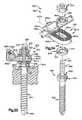
- FIG. 1is an exploded schematic perspective view of a surgical cannula constructed for use with the present invention, the cannula being shown in an expanded condition;
- FIG. 2is a schematic perspective view of the cannula of FIG. 1 with parts removed for clarity, the cannula being shown in a contracted condition;
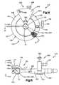
- FIG. 3is a schematic end view showing the cannula of FIG. 1 in the expanded position
- FIG. 4is a rollout view of a part of the cannula of FIG. 1 ;
- FIG. 5is a schematic sectional view of one position of the cannula of FIG. 1 during a surgical procedure
- FIG. 6is an exploded schematic perspective view of another surgical cannula in accordance with the present invention, the cannula being shown in an expanded condition;
- FIG. 7is a schematic perspective view of the cannula of FIG. 6 , the cannula being shown in a contracted condition;
- FIG. 8is an exploded schematic perspective view of still another surgical cannula in accordance with the present invention, the cannula being shown in an expanded condition;
- FIG. 9is a schematic sectional view of part of the cannula of FIG. 8 ;
- FIG. 10is a schematic end view, similar to FIG. 3 , of part of another cannula in an expanded condition.
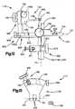
- FIG. 11is a schematic elevational view of a support apparatus in accordance with the present invention.
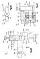
- FIG. 12is a schematic view taken along line 12 - 12 in FIG. 11 ;
- FIG. 13is a schematic view taken along line 13 - 13 in FIG. 11 showing part of the support apparatus of FIG. 11 ;
- FIG. 14is a schematic view taken along line 14 - 14 in FIG. 11 showing part of the support apparatus of FIG. 11 ;
- FIG. 15is a schematic view taken along line 15 - 15 in FIG. 11 with parts removed;
- FIG. 16is a schematic view taken along line 16 - 16 in FIG. 11 ;
- FIG. 17is a schematic view taken along line 17 - 17 in FIG. 11 showing part of the support apparatus of FIG. 11 ;
- FIG. 18is a schematic view taken along line 18 - 18 in FIG. 11 showing part of the support apparatus of FIG. 11 ;
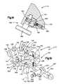
- FIG. 19is a schematic perspective view of the support apparatus of FIG. 11 ;
- FIG. 20is a schematic perspective view of the support apparatus of FIG. 11 looking at the support apparatus from an angle different than FIG. 19 ;
- FIG. 21is a schematic perspective view of the support apparatus of FIG. 11 looking at the support apparatus from an angle different than FIGS. 19 and 20 ;
- FIG. 22is a sectional view taken approximately along line 22 - 22 of FIG. 14 ;
- FIG. 23is an enlarged view of a part of FIG. 22 ;
- FIG. 24is a schematic end view taken along line 24 - 24 in FIG. 15 with parts removed;
- FIG. 25is a view further illustrating parts shown in FIG. 15 ;
- FIG. 26is a sectional view taken approximately along line 26 - 26 of FIG. 25 ;
- FIG. 27is a schematic view showing part of the support apparatus of FIG. 11 with an associated known mechanical arm;
- FIG. 28is a schematic view of another feature of part of the support apparatus of FIG. 11 ;
- FIG. 29is a schematic view of a fixation assembly attached to vertebrae of a patient.
- FIG. 30is a schematic view taken along line 30 - 30 of FIG. 29 ;
- FIG. 31is an exploded schematic perspective view of part of the assembly of FIG. 29 ;
- FIG. 32is a schematic view of another fixation assembly attached to vertebrae of a patient.
- FIG. 33is a schematic view taken along line 33 - 33 of FIG. 32 ;
- FIG. 34is an exploded schematic perspective view of part of the assembly of FIG. 32 ;
- FIG. 35Ais a schematic sectional view of one position of a cannula during a surgical procedure in accordance with one feature of the present invention.
- FIG. 35Bis a schematic sectional view of another position of the cannula during the surgical procedure of FIG. 35A ;
- FIG. 36is a schematic sectional view of the position of another cannula during a surgical procedure in accordance with another feature of the present invention.
- FIG. 37is a schematic sectional view of positions of cannulae during a surgical procedure in accordance with still another feature of the present invention.
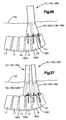
- FIG. 38is a schematic view of part of an alternative fixation element to be attached to vertebrae of a patient, similar to FIG. 29 ;
- FIG. 39is a schematic exploded view of part of a cutting tool used with a method in accordance with the present invention.
- FIG. 40is a schematic view of part of the cutting tool of FIG. 39 .
- the present inventionis directed to a method and apparatus for use in a surgical procedure, and particularly for fixing together the vertebrae of a patient at a surgical site.
- the methodinvolves the use of a cannula, an adjustable support for the cannula, surgical instruments, and a viewing device.
- FIGS. 1-5illustrate one suitable cannula 10 constructed for use in a method in accordance with the present invention.
- the cannula 10is a tubular structure 12 centered on an axis 14 .
- the tubular structure 12defines a passage 16 through the cannula 10 .
- Surgical instrumentsmay be inserted into the body during surgery through the passage 16 .
- the tubular structure 12comprises a first tubular portion 20 and a second tubular portion 40 attached to the first tubular portion.
- the first tubular portion 20is preferably made of a length of stainless steel tubing, but could alternatively be made of another suitable material such as a radiolucent material.
- the first tubular portion 20has a proximal end 22 and a distal end 24 .
- Parallel cylindrical inner and outer surfaces 26 and 28respectively, extend between the ends 22 , 24 of the first tubular portion 20 .
- the inner surface 26defines a first passage portion 30 of the passage 16 through the cannula 10 .
- the first passage portion 30has a diameter D 1 that is preferably in the range from 10 mm to 30 mm (or approximately 0.4 to 1.2 inches).
- the inner surface 26may have a non-reflective coating.
- the non-reflective coatingreduces glare on any video image produced by a video camera inserted through the passage 16 .
- the inner surface 26may not have the coating.
- the second tubular portion 40 of the tubular structure 12is attached to the distal end 24 of the first tubular portion 20 .
- the second tubular portion 40is preferably made from stainless steel, but could alternatively be made from another suitable material such as a radiolucent material.
- the second tubular portion 40comprises an arcuate segment 42 of sheet stock.
- the arcuate segment 42includes first and second arcuate edges 44 , 46 , respectively, and first and second planar edges 48 , 50 , respectively.
- the first and second planar edges 48 , 50are rolled in an overlapping manner to form the tubular configuration of the second tubular portion 40 .
- first and second arcuate edges 44 , 46define oppositely disposed first and second ends 60 , 62 ( FIGS. 1 and 2 ), respectively, of the second tubular portion.
- the first and second ends 60 , 62are connected by a central portion 64 .
- the first end 60 of the second tubular portion 40is attached to the distal end 24 of the first tubular portion 20 by a single fastener, such as a rivet 66 .
- the rivet 66extends through two aligned apertures 68 ( FIG. 4 ) at the first end 60 of the second tubular portion 40 .
- the first end 60 of the second tubular portion 40is pivotable about the rivet 66 .
- the second tubular portion 40includes parallel inner and outer surfaces 70 , 72 ( FIGS. 1 and 2 ), respectively, extending between the first and second ends 60 , 62 .
- the inner surface 70defines a second passage portion 74 of the passage 16 through the cannula 10 that extends as a continuation of the first passage portion 30 of the first tubular portion 20 .
- the inner surface 70may optionally have a non-reflective coating (not shown).
- An arcuate slot 80is formed in the second tubular portion 40 and extends between the inner and outer surfaces 70 , 72 of the second tubular portion.
- the arcuate slot 80extends along a curvilinear path in the central portion 64 of the second tubular portion 40 toward the second end 60 of the second tubular portion.
- the arcuate slot 80has a first terminal end 82 located in the central portion 64 of the second tubular portion 40 .
- a second terminal end 84 of the arcuate slot 80is located adjacent the intersection of the second arcuate edge 46 and the first planar edge 48 of the arcuate segment 42 .
- a guide pin 90is attached to the inner surface 70 of the second tubular portion 40 adjacent the intersection of the second arcuate edge 46 and the second planar edge 50 .
- the guide pin 90In the tubular configuration of the second tubular portion 40 , the guide pin 90 is located in the arcuate slot 80 and is movable along the curvilinear path of the arcuate slot.
- a washer 92is secured at an inner end of the guide pin 90 to retain the guide pin in the arcuate slot 80 .
- the second tubular portion 40 of the tubular structure 12is expandable from a contracted condition shown in FIG. 2 to an expanded condition shown in FIG. 1 .
- the guide pin 90is located at the first terminal end 82 of the arcuate slot 80 in the second tubular portion 40 and the second passage portion 74 defined by the second tubular portion is generally cylindrical in shape.
- the second passage 74has a generally constant diameter D 2 ( FIGS. 2 and 3 ) that is approximately equal to the diameter D 1 of the first tubular portion 20 .
- the cross-sectional area of the second passage portion 74 at the second end 62 of the second tubular portion 40which is a function of the diameter D 2 , is approximately the same as the cross-sectional area at the first end 60 of the second tubular portion and is approximately the same as the cross-sectional area of the first passage portion 30 in the first tubular portion 20 .
- the guide pin 90is located at the second terminal end 84 of the arcuate slot 80 in the second tubular portion 40 and the second tubular portion has a generally conical configuration.
- the second passage portion 74has a diameter D 3 ( FIG. 3 ) that is larger then the diameter D 2 of the second passage portion at the first end 60 (typically 14 mm to as large as 60 mm or 0.6 to 2.4 inches).
- the diameter D 3 of the second passage portion 74 at the second end 62 of the second tubular portionis 40% to 90% greater than the diameter D 1 of the second passage portion at the first end 60 .
- the cross-sectional area of the second passage portion 74 at the second end 62 of the second tubular portion 40which is function of the diameter D 3 , is 16% to 81% greater than the cross-sectional area of the second passage portion at the first end 60 of the second tubular portion.
- the cross-sectional area of the second passage portion 74 at the second end 62 of the second tubular portion 40may be large enough to overlie a major portion of at least two, and as many as three, adjacent vertebrae.
- the cannula 10includes an outer layer 100 ( FIG. 1 ) for maintaining the second tubular portion 40 of the cannula in the contracted condition. It is contemplated that other suitable means for maintaining the second tubular portion 40 in the contracted condition may be employed.
- the outer layer 100comprises a section of plastic tubing 102 which is heat shrunk over both the first and second tubular portions 20 , 40 to hold the second tubular portion in the contracted condition.
- a loop of polyester string 104 for tearing the tubing 102is wrapped around the tubing so that it extends both underneath, and on top of, the tubing.
- An outer end 106 of the string 104extends beyond the tubing 102 .
- FIG. 1shows an actuatable device 111 for expanding the second tubular portion 40 from the contracted condition to the expanded condition.
- the actuatable device 111comprises a manually operated expansion tool 112 .
- the expansion tool 112resembles a common pair of scissors and has a pair of legs 114 pivotally connected to one another.
- the expansion tool 112includes a frustoconical end section 116 forming a pair of frustoconical halves 118 .
- Each of the frustoconical halves 118extends from a respective one of the legs 114 of the expansion tool 112 .
- suitable means for expanding the second tubular portion 40 toward the expanded conditionmay be employed, such as an inflatable balloon (not shown).
- the cannula 10is inserted into the body of a patient in the contracted condition.
- the outer end 106 of the string 104is then manually pulled on by a surgeon, nurse, or other technician. Pulling on the string 104 tears the tubing 102 most of the way along the tubing, thereby freeing the second tubular portion 40 for expansion.
- the tubing 102in its torn condition, may remain attached or secured to the first tubular portion 20 .
- the expansion tool 112is inserted into the passage 16 in the cannula 10 until the frustoconical end section 114 is located at the second end 62 of the second tubular portion 40 .
- the legs 114 of the expansion tool 112are manually separated, causing the frustoconical halves 118 to separate.
- a radially outward directed forceis exerted on the inner surface 70 of the second tubular portion 40 by the halves 118 , causing the second tubular portion to expand toward the expanded condition.
- the guide pin 90slides from the first terminal end 82 of the arcuate slot 80 to the second terminal end 84 of the arcuate slot to permit the expansion of the second tubular portion 40 .
- the expansion tool 112can be rotated about the axis 14 to ensure that the second tubular portion 40 of the cannula 10 is completely expanded to the expanded condition.
- the expansion tool 112is then collapsed and removed so that one or more surgical instruments (indicated schematically at 21 in FIG. 5 ) and a viewing element can be received through the cannula 10 and inserted into a patient's body 130 .
- the expandable second tubular portion 40 of the cannula 10provides a significantly larger working area for the surgeon inside the body 130 within the confines of the cannula.
- the simultaneous use of a number of surgical instruments(such as steerable instruments, shavers, dissectors, scissors, forceps, retractors, dilators, etc.) is possible with the expandable cannula 10 .
- the expanded second tubular portion 40can dilate and locally retract and separate spinalis muscle and soft tissues from the vertebrae thereby creating an endoscopic operating field at the surgical site.
- This endoscopic operating field within the spinal musclesdiffers from arthroscopic, laparoscopic, or cystoscopic working spaces in that there is no physiologic space or defined tissue plane that can be insufflated with air or distended with fluid.
- FIGS. 6-7illustrate another suitable cannula 1150 constructed for use in a method in accordance with the present invention.
- the cannula 1150includes a tubular structure 1152 centered on an axis 1154 .
- the tubular structure 1152defines a passage 1156 through the cannula 1150 .
- Surgical instrumentsmay be inserted into the body 130 during endoscopic surgery through the passage 1156 .
- the tubular structure 1152( FIG. 6 ) comprises a first tubular portion 1160 and a second tubular portion 1180 attached to the first tubular portion.
- the first tubular portion 1160is preferably made of a length of stainless steel tubing, but could alternatively be made of another suitable material such as a radiolucent material.
- the first tubular portion 1160has a proximal end 1162 and a distal end 1164 .
- Parallel cylindrical inner and outer surfaces 1166 , 1168extend between the ends 1162 , 1164 of the first tubular portion 1160 .
- the first tubular portion 1160has a thickness measured perpendicular to the surfaces 1166 , 1168 in the range of approximately 0.5 mm to approximately 1.0 mm (or 0.02 inches to 0.04 inches).
- the inner surface 1166defines a first passage portion 1170 of the passage 1156 through the cannula 1150 .
- the first passage portion 1170has a diameter d 1 that is preferably in the range of 10 mm to 30 mm (or approximately 0.4 inches to 1.2 inches).
- the inner surface 1166may have a non-reflective coating 1174 .
- the non-reflective coating 1174reduces glare on any video image produced by a video camera inserted through the passage 1156 .
- the inner surface 1166may not have the coating 1174 .
- the second tubular portion 1180 ( FIG. 6 ) of the tubular structure 1152is attached to the distal end 1164 of the first tubular portion 1160 .
- the second tubular portion 1180is preferably made from stainless steel, but could alternatively be made from another suitable material such as a radiolucent material.
- the second tubular portion 1180includes an arcuate segment 1182 of sheet stock.
- the arcuate segment 1182includes first and second arcuate edges 1184 , 1186 .
- the arcuate segment 1182also includes a first planar edge 1188 and a second planar edge (not shown) extending between the arcuate edges 1184 , 1186 .
- the first 1188 and second planar edgesare rolled in an overlapping manner to form the tubular configuration of the second tubular portion 1180 .
- first and second arcuate edges 1184 , 1186define oppositely disposed first and second ends 1200 , 1202 of the second tubular portion.
- the first and second ends 1200 , 1202are connected by a central portion 1204 .
- the first end 1200 of the second tubular portion 1180is attached to the distal end 1164 of the first tubular portion 1160 by a suitable fastener, such as a screw 1206 and nut 1208 threaded onto the screw.
- the second tubular portion 1180may be connected to the first tubular portion 1160 by a rivet.
- the screw 1206extends through two aligned apertures 1240 at the first end 1200 of the second tubular portion 1180 .
- the first end 1200 of the second tubular portion 1180is pivotable about the screw 1206 .
- the second tubular portion 1180includes parallel inner and outer surfaces 1212 , 1214 extending between the first and second ends 1200 , 1202 .
- the inner surface 1212defines a second passage portion 1216 of the passage 1156 through the cannula 1150 that extends as a continuation of the first passage portion 1170 in the first tubular portion 1160 .
- the second tubular portion 1180has a thickness measured perpendicular to the surfaces 1212 , 1214 in the range of approximately 0.075 mm to 0.15 mm (or 0.003 inches to 0.006 inches).
- the inner surface 1212has a non-reflective coating 1218 .
- the non-reflective coating 1218reduces glare on any video image produced by a camera inserted through the passage 1156 .
- the inner surface 1212may not have the coating 1218 .
- An arcuate slot 1220( FIG. 6 ) is formed in the second tubular portion 1180 and extends between the inner and outer surfaces 1212 , 1214 of the second tubular portion.
- the arcuate slot 1220extends along a curvilinear path in the central portion 1204 of the second tubular portion 1180 toward the end 1184 of the second tubular portion.
- the arcuate slot 1220has a first terminal end (not shown) located in the central portion 1204 of the second tubular portion 1180 .
- a second terminal end 1224 of the arcuate slot 1220is located adjacent the intersection of the second arcuate edge 1186 and the planar edge 1188 of the arcuate segment 1182 .
- a guide member or screw 1230is attached to the inner surface 1212 of the second tubular portion 1180 adjacent the intersection of the second arcuate edge 1186 and the second planar edge (not shown).
- a guide pincould be used instead of the screw 1230 .
- the guide member 1230is located in the arcuate slot 1220 and is movable along the curvilinear path of the arcuate slot.
- the second tubular portion 1180 of the tubular structure 1152is expandable from a contracted condition, shown in FIG. 7 , to an expanded condition, shown in FIG. 6 .
- the guide member 1230is located at the first terminal end (not shown) of the arcuate slot 1220 in the second tubular portion 1180 and the second passage portion 1216 defined by the second tubular portion is generally cylindrical in shape.
- the second passage 1216has a generally constant diameter d 2 that is approximately equal to the diameter d 1 of the first tubular portion 1160 .
- the cross-sectional area of the second passage portion 1216 at the second end 1202 of the second tubular portion 1180which is a function of the diameter d 2 , is approximately the same as the cross-sectional area at the first end 1200 of the second tubular portion and is approximately the same as the cross-sectional area of the first passage portion 1170 in the first tubular portion 1160 .
- the guide member 1230is located at the second terminal end 1224 of the arcuate slot 1220 in the second tubular portion 1180 and the second tubular portion has a generally conical configuration.
- the second passage portion 1216has a diameter d 3 that is larger than the diameter d 2 of the second passage portion at the first end 1200 .
- the diameter d 3 of the second passage portion 1216 at the second end 1202 of the second tubular portionis 40% to 90% greater than the diameter d 2 of the second passage portion at the first end 1200 .
- the cross-sectional area of the second passage portion 1216 at the second end 1202 of the second tubular portion 1180which is function of the diameter d 3 , is greater than the cross-sectional area of the second passage portion at the first end 1200 of the second tubular portion.
- the cannula 1150includes an outer member (not shown) for maintaining the second tubular portion 1180 of the cannula in the contracted condition. It is contemplated that other suitable means for maintaining the second tubular portion 1180 in the contracted condition may be employed.
- the outer membermay be similar to the layer 100 shown in FIG. 1 and include a section of plastic tubing which is heat shrunk over both the first and second tubular portions 1160 , 1180 to hold the second tubular portion 1180 in the contracted condition.
- a loop of nylon string (not shown) for tearing the tubingmay be wrapped around the tubing so that it extends both underneath and on top of the tubing. An outer end of the string may extend beyond the tubing.
- the cannula 1150is inserted through an incision into the body 130 of a patient in the contracted condition.
- the second tubular portion 1180is inserted inside the body 130 .
- the first tubular portion 1160is inserted into the incision so that the first tubular portion extends from an exterior of the body 130 to inside the body.
- the outer end of the stringmay then be manually pulled on by a surgeon, nurse, or other technician. Pulling on the string tears the tubing that is then removed from the cannula 1150 . With the tubing removed, the second tubular portion 1180 of the cannula 1150 is thereby released for expansion toward the expanded condition.
- the expansion tool 112shown in FIG. 1 , may be inserted into the passage 1156 in the cannula 1150 until the frustoconical end section 114 is located at the second end 1202 of the second tubular portion 1180 .
- the legs 114 of the expansion tool 112are manually separated, causing the frustoconical halves 118 to separate.
- a radially outwardly directed forceis exerted on the inner surface 1212 of the second tubular portion 1180 by the halves 118 , causing the second tubular portion to expand toward the expanded condition.
- the guide member 1230slides from the first terminal end of the arcuate slot 1220 to the second terminal end 1224 of the arcuate slot to permit the expansion of the second tubular portion 1180 .
- the expansion tool 112can be rotated about the axis 1154 to ensure that the second tubular portion 1180 of the cannula 1150 is completely and uniformly expanded to the expanded condition.
- the expansion tool 112is then collapsed and removed so that one or more surgical instruments and a viewing element can be received through the cannula 1150 and inserted into a patient's body 130 .
- the thickness of the second tubular portion 1180allows the second tubular portion to deform as the second tubular portion expands. As the second tubular portion 1180 expands and engages tissue in the body 130 , the tissue resists expansion of the second tubular portion. The second tubular portion 1180 may deform slightly to prevent the second tubular portion from being damaged while expanding. Because of this deformation, the expanded second tubular portion 1180 may be elliptical-conical in shape.
- the expandable second tubular portion 1180 of the cannula 1150provides a significantly larger working area for the surgeon inside the body 130 within the confines of the cannula.
- endoscopic surgical instrumentsincluding but not limited to steerable instruments, shavers, dissectors, scissors, forceps, retractors, dilators, and video cameras, is made possible by the expandable cannula 1150 .
- FIGS. 8-9illustrate still another suitable cannula 1250 constructed for use in a method in accordance with the present invention.
- the tubular portions 1160 and 1180are connected by a screw 1206 and nut 1208 and the guide member is a screw 1230 .
- the tubular portionsare connected by a rivet and the guide member is a rivet.
- the cannula 1250is similar to the cannula 1150 shown in FIGS. 6-7 with regard to the other features. Accordingly, only the rivets will be described in detail.
- the cannula 1250( FIG. 8 ) includes a tubular structure 1252 centered on an axis 1254 .
- the tubular structure 1252defines a passage 1256 through the cannula 1250 .
- the tubular structure 1252includes a first tubular portion 1260 and a second tubular portion 1280 attached to the first tubular portion.
- the first tubular portion 1260has a proximal end 1262 and a distal end 1264 .
- Parallel cylindrical inner and outer surfaces 1266 and 1268extend between the ends 1262 , 1264 of the first tubular portion 1260 .
- the inner surface 1266defines a first passage portion 1270 of the passage 1256 through the cannula 1250 .
- the inner surface 1266may optionally have a non-reflective coating (not shown).
- the second tubular portion 1280( FIG. 8 ) of the tubular structure 1252 is attached to the distal end 1264 of the first tubular portion 1260 .
- the second tubular portion 1280includes an arcuate segment 1282 of sheet stock.
- the arcuate segment 1282includes first and second arcuate edges 1284 , 1286 .
- the arcuate segment 1282also includes a first planar edge 1288 and a second planar edge (not shown) extending between the arcuate edges 1284 , 1286 .
- the first 1288 and second planar edgesare rolled in an overlapping manner to form the tubular configuration of the second tubular portion 1280 .
- first and second arcuate edges 1284 , 1286define oppositely disposed first and second ends 1300 , 1302 of the second tubular portion.
- the first and second ends 1300 , 1302are connected by a central portion 1304 .
- the first end 1300 of the second tubular portion 1280is attached to the distal end 1264 of the first tubular portion 1260 by a rivet 1306 .
- the rivet 1306extends through two aligned apertures 1340 at the first end 1300 of the second tubular portion 1280 .
- the first end 1300 of the second tubular portion 1280is pivotable about the rivet 1306 .
- the rivet 1306( FIGS. 8 and 9 ) has a first portion 1308 and a second portion 1310 .
- the first portion 1308has a shaft 1312 extending from a head 1314 .
- the shaft 1312extends through the apertures 1340 in the tubular portion 1280 and the head engages the inner surface 1266 of the first tubular portion 1260 .
- a generally cylindrical opening 1316extends through the shaft 1312 and the head 1314 .
- the second portion 1310 of the rivet 1306has a shaft 1318 extending from a head 1320 .
- the shaft 1318extends into the opening 1316 in the first portion 1308 of the rivet 1306 and the head 1320 engages the second tubular portion 1280 .
- the shaft 1318 of the second portion 1310extends into the opening 1316 in the first portion 1308 to connect the first and second portions of the rivet 1306 and pivotally connect the second tubular portion 1280 to the first tubular portion 1260 .
- the second tubular portion 1280( FIG. 8 ) includes parallel inner and outer surfaces 1322 , 1324 extending between the first and second ends 1300 , 1302 .
- the inner surface 1322defines a second passage portion 1326 of the passage 1256 through the cannula 1250 that extends as a continuation of the first passage portion 1270 in the first tubular portion 1260 .
- the inner surface 1322may optionally have a non-reflective coating (not shown).
- An arcuate slot 1330is formed in the second tubular portion 1280 and extends between the inner and outer surfaces 1322 , 1324 of the second tubular portion.
- the arcuate slot 1330extends along a curvilinear path in the central portion 1304 of the second tubular portion 1280 toward the end 1284 of the second tubular portion.
- the arcuate slot 1330has a first terminal end (not shown) located in the central portion 1304 of the second tubular portion 1280 .
- a second terminal end 1334 of the arcuate slot 1330is located adjacent the intersection of the second arcuate edge 1286 and the first planar edge 1288 of the arcuate segment 1282 .
- a rivet 1336is attached to the inner surface 1322 of the second tubular portion 1280 adjacent the intersection of the second arcuate edge 1286 and the second planar edge (not shown).
- a guide pinmay be used instead of the rivet 1336 .
- the rivet 1336In the tubular configuration of the second tubular portion 1280 , the rivet 1336 is located in the arcuate slot 1330 and is movable along the curvilinear path of the arcuate slot.
- a washer 1338retains the rivet 1336 in the arcuate slot 1330 .
- the rivet 1336is generally similar to the rivet 1306 and, therefore, will not be described in detail.
- the rivet 1336has a first portion 1342 and a second portion 1344 .
- the first portion 1342has a shaft 1346 extending from a head 1348 .
- the shaft 1346extends through the slot 1330 and the head 1348 engages the washer 1338 .
- a cylindrical opening 1350extends through the shaft 1346 and the head 1348 .
- the second portion 1344 of the rivet 1336has a shaft 1352 extending from a head 1354 .
- the shaft 1352extends into the opening 1350 in the first portion 1342 of the rivet 1336 and the head 1354 engages the outer surface 1324 of the second tubular portion 1280 .
- the shaft 1352extends into the opening 1350 to connect the first portion 1342 of the rivet 1336 to the second portion 1344 .
- the second tubular portion 1280 of the tubular structure 1252is expandable from a contracted condition to an expanded condition, shown in FIG. 8 .
- the rivet 1336is located at the first terminal end (not shown) of the arcuate slot 1330 in the second tubular portion 1280 and the second passage portion 1326 defined by the second tubular portion is generally cylindrical in shape.
- the second passage portion 1326has a generally constant diameter that is approximately equal to the diameter of the first tubular portion 1260 .
- the cross-sectional area of the second passage portion 1326 at the second end 1302 of the second tubular portion 1280is approximately the same as the cross-sectional area at the first end 1300 of the second tubular portion and is approximately the same as the cross-sectional area of the first passage portion 1270 in the first tubular portion 1260 .
- the rivet 1336is located at the second terminal end 1334 of the arcuate slot 1330 in the second tubular portion 1280 and the second tubular portion has a generally conical configuration.
- the second passage portion 1326has a diameter that is larger than the diameter of the second passage portion at the first end 1300 .
- the cross-sectional area of the second passage portion 1326 at the second end 1302 of the second tubular portion 1280is greater than the cross-sectional area of the second passage portion at the first end 1300 of the second tubular portion.
- the cannula 1250is inserted through an incision into the body 130 of a patient in the contracted condition.
- the second tubular portion 1280is inserted inside the body 130 .
- the first tubular portion 1260is inserted into the incision so that the first tubular portion extends from an exterior of the body 130 to inside the body.
- Restraint tubing(not shown) is removed from the cannula 1250 by a surgeon, nurse or other technician. With the tubing removed, the second tubular portion 1280 of the cannula 1250 is thereby released for expansion toward the expanded condition.
- the expansion tool 112shown in FIG. 1 , is inserted into the passage 1256 in the cannula 1250 until the frustoconical end section 114 is located at the second end 1302 of the second tubular portion 1280 .
- the legs 114 of the expansion tool 112are manually separated, causing the frustoconical halves 118 to separate also.
- a radially outwardly directed forceis exerted on the inner surface 1312 of the second tubular portion 1280 by the halves 118 , causing the second tubular portion to expand toward the expanded condition.
- the rivet 1336slides from the first terminal end of the arcuate slot 1330 to the second terminal end 1334 of the arcuate slot to permit the expansion of the second tubular portion 1280 .
- the expansion tool 112is then collapsed and removed so that one or more surgical instruments and a viewing element can be received through the cannula 1250 and inserted into a patient's body 130 .
- the expandable second tubular portion 1280 of the cannula 1250provides a significantly larger working area for the surgeon inside the body 130 within the confines of the cannula.
- endoscopic surgical instrumentsincluding but not limited to steerable instruments, shavers, dissectors, scissors, forceps, retractors, dilators, and video cameras, is made possible by the expandable cannula 1250 .
- a second tubular portion 1040 of the cannulae 10 , 1150 , and/or 1250may be elliptical in shape in order to provide access to a larger area.
- the longitudinal dimension D 4 of the second portion 1040may expand to as much as 65 mm (or 2.6 inches) from a contracted condition (not shown).
- FIGS. 11-28illustrate one suitable support apparatus 110 for use in a method in accordance with the present invention.
- the support apparatus 110includes a first support 120 , a second support 140 , a first adjustment mechanism 160 , a second adjustment mechanism 180 , and a third adjustment mechanism 900 .
- the first support 120is associated with the cannula 10 , 1150 , or 1250 (hereinafter only the cannula 10 will be referred to with respect to the support apparatus 110 ) and has a circular perimeter 121 .
- the perimeter 121has a center 122 located on the axis 14 .
- the first support 120comprises a circular platform, or disk 124 , which has a circular opening 126 in the central area of the disk 124 for receiving the proximal end 22 of the cannula 10 .
- the circular opening 126has a center located on the axis 14 .
- the proximal end 22 of the cannula 10can be easily inserted into, and removed from, the opening 126 .
- the disk 124has a projection portion 120 a , which is located adjacent the perimeter 121 of the disk 124 .
- the disk 124has an upper circular surface area 124 a , which surrounds the opening 126 .
- the second support 140supports a viewing device 200 including a camera head 201 and an endoscope 202 with a rod and lens assembly 203 , herein referred to as a viewing element, extending down through the passage 16 of the cannula 10 .
- the second support 140includes a body 142 having an opening 144 through which the viewing device 200 extends and a clamp 146 for clamping the viewing device 200 to the body 142 in the opening 144 .
- the clamp 146includes a threaded set screw 148 for securing the viewing device 200 to the body 142 .
- the set screw 148has a manually rotatable knob 148 a and a stem threaded into the body 142 . When rotated, the screw 148 moves axially relative to the body 142 to clamp (or release) the viewing device 200 depending on the direction of rotation of the screw 148 .
- the body 142 of the second support 140further includes two extension arms 151 , 152 ( FIG. 13 ) for supporting the endoscope 202 .
- Each extension arm 151 , 152includes a threaded bore for receiving a resilient detent member, or ball plunger 400 .
- a ball plunger 400is illustrated at another location in the support apparatus 110 .
- Each ball plunger 400including those in the extension arms 151 , 152 , has an externally threaded tubular body 402 with a cylindrical cavity 404 located therein.
- the cavity 404houses a projection 406 and a coiled spring 408 .
- the projections 406 of the two ball plungers 400 of the extension arms 151 , 152are spherical detent members 420 in the form of balls (not shown).
- the spring 408urges each projection 406 against a lip portion 409 of the body 402 .
- the lip portion 409is located at one end of the cavity 404 .
- the other ball plungers 400 of the apparatus 10have projections 406 with hemispherical extensions 420 and shoulder portions 422 .
- the endoscope 202has corresponding hemispherical recesses (not shown) for receiving the spherical detent members (balls) of the ball plungers 400 which are located in extension arms 151 , 152 .
- the springs 408will compress in each ball plunger 400 in each extension arm 151 , 152 and the spherical detent members will move inward of each cavity 404 and then spring back into the hemispherical recesses in the endoscope 202 .
- the entire viewing device 200will thus be secured between the extension arms 151 , 152 , but may be removed by overcoming the biasing force of the spherical detent members of each ball plunger 400 in the extension arms 151 , 152 .
- the ball plunger 400further includes a head portion 430 with a slot 432 for engaging a tool, such as a screwdriver.
- the ball plunger 400may be threadedly adjusted within the threaded bore of either extension arm 151 , 152 to alter the distance that the spherical detent member 420 projects away from the extension arms 151 , 152 (toward each other). This distance, along with the stiffness of each spring 408 , will determine the holding force by which the endoscope 202 is secured between the extension arms 151 , 152 .
- the first adjustment mechanism 160provides for relative axial adjustment of the cannula 10 and the first support 120 along the axis 14 .
- the first adjustment mechanism 160includes a first toothed rack member 162 , a cannula gripper mechanism 164 fixedly connected to the first rack member 162 , a first manually adjustable, rotatable knob 166 rotatably carried by the projection portion 120 a of the first support 120 , and a first gear member 165 ( FIG. 17 ) rotatable by the first knob 166 and in meshing engagement with the teeth 163 of the first rack member.
- the first support 120 and, in particular, the projection portion 120 arotatably carries the first gear member 165 ( FIG. 17 ).
- the first rack member 162is secured to slide axially within the first support 120 and the projection portion 120 a by two ball plungers 400 ( FIG. 17 ).
- One ball plunger 400is tangentially threaded into a tapered, threaded bore ( FIG. 12 ) in the perimeter 121 of the first support 120 and the other is tangentially threaded into a threaded bore in the projection portion 120 a .
- the hemispherical extensions 420thus frictionally engage a smooth portion (without teeth 163 ) of the first rack member 162 and bias the first rack member 162 against the first support 120 and the projection portion 120 a . This biasing also maintains the engagement of the first rack member 162 and the first gear member 165 ( FIG. 17 ).
- the cannula gripper mechanism 164includes two gripper arms 172 , 174 for clamping against the outer surface of the cannula 10 , and a gripper actuating lever 176 for moving the arms 172 , 174 into engagement with the outer surface of the cannula 10 and for releasing the arms 172 , 174 from engagement with the cannula 10 .
- References in this application to gripping the outer surface 28 of the cannula 10are meant to also include the gripper arms 511 , 512 engaging the tubing 102 .
- the cannula gripper mechanism 164further includes a support pin 177 , a coiled spring 188 , a washer 189 with a bore (not shown), and a lock pin 190 .
- the support pin 177has a head 179 , a shaft 180 , and an oblong, or flat, end 181 that can mate with the bore in the washer 189 .
- Other suitable structurescould also be used.
- the coiled spring 188is interposed between the arms 172 , 174 .
- the flat end 181 of the support pin 177is inserted through a circular bore in the first clamp arm 172 , through the coil of the spring 188 , through a circular bore in the second arm 174 , and through the bore in the washer 189 .
- the flat end 181 of the support pin 177is then inserted into a slot 176 a in the lever 176 .
- the lock pin 190is inserted through a bore in the lever 176 and through a bore in the flat end 181 of the support pin 177 thereby securing the mechanism 164 together and allowing the lever 176 to rotate about the lock pin 190 .
- a camming surface 178 on the lever 176 adjacent the washer 189forces the arms 172 , 174 together to grip the cannula 10 as the lever 176 is rotated clockwise (as viewed in FIG. 15 ). Counterclockwise rotation of the lever 176 allows the spring 188 to force the arms 172 , 174 apart and releases the cannula 10 from the gripper mechanism 164 .
- the gripper mechanism 164When the gripper mechanism 164 is either gripping the cannula 10 or released from the cannula 10 and the knob 166 is rotated, the disk 124 and parts attached to the disk 124 will move along the axis 14 of the cannula 10 relative to the cannula 10 .
- the viewing device 200may be positioned on the support apparatus 110 and adjusted along the axis 14 by rotation of the first knob 166 .
- the second adjustment mechanism 180provides axial adjustment of the first and second supports 20 , 40 relative to each other along the axis 14 .
- the second adjustment mechanism 180includes a second toothed rack member 182 connected to the first support 120 , a second manually adjustable, rotatable knob 186 rotatably carried by the body 142 of the second support 140 , and a second toothed gear member 185 ( FIG. 18 ) rotatable by the second knob 186 and in meshing engagement with the teeth 183 of the second rack member 182 .
- the second support 140and in particular, the body 142 , rotatably carries the second gear member 185 ( FIG. 18 ).
- the body 142 of the second support 140may have a notch 149 which can fit around part 902 a of the third adjustment mechanism 900 and allow the lower surface of the body 142 to completely abut the disk 124 as the body 142 is brought into an axial position adjacent the disk 124 .
- the second rack member 182is secured to slide axially within the second support 140 by a ball plunger 40 . 0 ( FIG. 18 ).
- the ball plunger 400is tangentially threaded into a threaded bore in the side of the notch 149 of the second support 140 .
- the hemispherical extension 420thus frictionally engages a smooth portion (without teeth 183 ) of the second rack member 182 and biases the second rack member 182 against the second support 140 .
- the biasingalso maintains the engagement of the second rack member 182 and the second gear member 185 .
- Both sides of the notch 149have tapered portions 149 a , 149 b for facilitating insertion of the ball plunger 400 into the threaded bore of the notch 149 of the second support 140 .
- Rotation of the second knob 186causes the body 142 and the viewing device 200 attached thereto to move relative to the cannula 10 and disk 124 along the axis 14 .
- the third adjustment mechanism 900provides arcuate, circumferential adjustment of the second support 140 about the axis 14 relative to the first support 120 .
- the third adjustment mechanism 900includes a wedge-shaped support member 902 ( FIG. 14 ) fixedly connecting the second rack member 182 to a ring member 904 that is rotatably supported by the first support 120 and rotatable about the axis 14 relative to the first support 120 ( FIG. 22 ).
- the third adjustment mechanism 900further includes a third manually adjustable, rotatable knob 906 that is part of a set screw.
- the set screwis rotatably threaded into a projection portion 902 a of the support member 902 and is engageable with the circular perimeter 121 of the disk 124 of the first support 120 to lock the support member 902 in an arcuate position relative to the first support 120 and the axis 14 .
- the ring member 904is supported within a cylindrical, open ended recess 905 of the first support 120 .
- the recess 905is concentric about the axis 14 .
- the perimeter 904 a of the ring member 904has a groove 904 b for engaging a plurality of ball plungers 400 (preferably four equally spaced apart) threaded into the first support 120 .
- Each of these ball plungers 400is similar in construction.
- Each ball plunger 400is threaded radially into the perimeter 121 of the first support 120 to provide a hemispherical extension 420 extending into the recess 905 of the first support 120 .
- the ring member 904thus is biasingly supported within the recess 905 of the first support 120 and can rotatably slide within the recess 905 about the axis 14 .
- the ball plungers 400operatively support the ring member 904 in the recess 905 of the first support 120 .
- the ring member 904along with the second support 140 and the second and third adjustment mechanisms 180 , 900 , can be easily removed from the recess 905 for cleaning, maintenance, etc. of the parts by overcoming the force applied by the ball plungers 400 to the ring member 904 .
- the third knob 906is rotated to disengage the perimeter 121 of disk 124 , the body 142 and parts connected thereto can be manually rotated about the axis 14 . This causes the viewing device 200 to rotate about the axis 14 of the cannula 10 and enables the surgeon to view different parts of the surgical sight, as desired.
- the fixed connections of the first rack member 162 to a support arm 300 , the second rack member 182 to the wedge-shaped support member 902 , and the support member 902 to the ring member 904may be made by one or more suitable metal fasteners 290 , such as rivets or bolts.
- the entire support apparatus 110can be constructed from metal or any other suitable material having sufficient mechanical strength and durability. Certain parts may be made from materials permitting X-rays and other techniques for viewing the surgical sight (i.e., radiolucent parts). Other parts may also be made from non-magnetic materials to reduce electromagnetic interference (i.e., electromagnetic insulating parts).
- the gripper arms 172 , 174are a part of the support arm 300 for attaching the support apparatus 110 to a mechanical robotic arm 301 .
- the support arm 300includes an arm portion 302 that is formed integrally with the gripper arms 172 , 174 .
- the gripper arms 172 , 174are integrally constructed with the arm portion 302 .
- the support arm 300also includes an arm portion 303 .
- the arm portion 303has an attaching structure 304 , including a groove 305 , which snaps into a socket in the mechanical arm 301 .
- Detents of any suitable type and designated 306 in the mechanical arm 301hold the arm portion 303 in position in the socket in the mechanical arm 301 .
- the detents 306may be controlled by external actuation levers (not shown) on the mechanical arm 301 for manually releasing the arm portion 303 from the mechanical arm 301 .
- the arm portions 302 and 303are pivotally connected to each other by a fastener 310 .
- the fastener 310extends through an opening 311 in the arm portion 302 and threads into a threaded opening 312 in the arm portion 303 .
- the arm portions 302 , 303may pivot relative to each other about a pivot axis 314 .
- the pivot axis 314is centered on the axis of the fastener 310 and the axis of the threaded opening 312 .
- the arm portions 302 , 303are secured together against pivoting movement.
- the arm portions 303 , 302may pivot relative to each other about the axis 314 .
- the end of the arm portion 302which is adjacent to the arm portion 303 , has a convex surface 350 , which is curved about the axis 314 .
- the arm portion 303has a concave surface 351 , which is also curved about the axis 314 .
- the surfaces 350 , 351move concentrically relative to each other when the arm portions 303 , 302 pivot relatively about the axis 314 .
- the arm portion 303has a set of teeth 320 which encircle the axis 314 and which project axially toward a set of teeth 321 on the arm portion 302 .
- the teeth 321project axially toward the teeth 320 .
- the teeth 320 and the teeth 321mesh with each other and provide a locking action so that the arm portions 302 , 303 are positively locked against relative movement about axis 314 when the fastener 310 is tightly screwed into the opening 312 .
- the teeth 320 , 321comprise a lock which blocks relative rotation of the arm portions 302 , 303 about the axis 314 .
- the arm portions 302 , 303When the fastener 310 is loosened, the arm portions 302 , 303 may be rotated relative to each other about the axis 314 . Thus, the arm portions 302 , 303 may pivot relative to each other to adjust the position of the support apparatus 110 .
- a cylindrical projection 325is welded to the arm portion 303 .
- the projection 325 and arm portion 303are fixedly connected together.
- the projection 325is centered on the axis 314 and contains a chamber 328 .
- the chamber 328communicates with a fluid passage 329 in a male fluid connector 331 .
- the male connector 331attaches to a male connector 333 on the mechanical arm 301 by means of a flexible hose 392 so that the fluid passage 329 communicates with a fluid passage in the mechanical arm 301 .
- the chamber 328is closed at its upper end by a cap 335 .
- the cap 335has an opening 336 centered on the axis 314 .
- the opening 336communicates with the chamber 328 .
- a manually movable internal valve member 340biasingly closes the opening and blocks the chamber 328 from communicating with the ambient air surrounding the support arm 300 .
- the valve member 340is connected to a stem 341 , which is also centered on the axis 314 .
- the stem 341has a knob or button 343 on its end that may be manually depressed to move the stem 341 and valve member 340 downward into the chamber 328 .
- the stem 341 and valve member 340are so moved, the chamber 328 is in communication with the ambient air surrounding the device due to the unblocking of the opening 336 .
- the mechanical arm 301is a known device and is of the type generally disclosed in U.S. Pat. No. 4,863,133.
- the mechanical arm 301is sold by Leonard Medical, Inc. 1464 Holcomb Road, Huntington Valley, Pa., 19006.
- the mechanical arm 301includes relatively movable parts, which permit movement and adjustment of the support apparatus 110 in a variety in planes, directions, and orientations.
- the mechanical arm 301permits easy movement when a vacuum is not applied to the arm 301 . When a vacuum is applied to the arm 301 , relative movement of the parts of the arm 301 is resisted, and therefore adjustment of the support apparatus 110 is difficult.
- the chamber 328loses its vacuum and the pressure in the chamber 328 increases toward ambient pressure.
- the passage 329communicates this pressure increase to the mechanical arm 301 , and thus the parts of the mechanical arm 301 are free to move and allow for adjustment of the position of the support apparatus 110 by the surgeon.
- the support arm 300is snapped into the socket of the mechanical arm 301 where it is held by the detent 306 .
- the surgeonmay then depress the button 343 and relatively move parts of the mechanical arm 301 , as well as the support apparatus 110 into the position where the surgeon desires the support apparatus 110 to be.
- This positionmay be where the opening 126 in the disk 124 is aligned with the proximal end 16 of the cannula 10 that has been positioned in the patient's body with the distal end 24 of the cannula 10 being located in an incision in the body of the patient.
- the viewing device 200may be mounted on the support apparatus 110 , and the surgeon may make adjustments prior to and during the surgical procedure as desired, as described above.
- the support apparatus 110may include a second support with a fourth adjustment mechanism 500 for rotating the viewing device 200 about an axis 501 ( FIG. 20 ) defined by the ball plungers 400 of the extension arms 151 , 152 when set screw 148 is not clamping the viewing device 200 to the body 142 .
- the axis 501is offset from the axis 14 of the cannula 10 and perpendicular to the axis 14 of the cannula 10 .
- Rotation of the viewing device 200 about axis 501causes the endoscope 200 and the rod and lens assembly 203 to move perpendicular to the axis 14 of the cannula 10 . This rotation will result in adjustment of the position of the rod and lens assembly 203 in a radial direction transverse to the axis 14 .
- the spring-loaded connections of the spherical detent members 420 of the ball plungers 400 and the hemispherical recesses of the endoscope 202allow rotation about the axis 501 when the set screw 148 is released from clamping engagement of the viewing device 200 .
- the fourth adjustment mechanism 500includes a threaded bore 510 in the second support 140 and an adjustable member 520 for moving (vertically as viewed in the Figs.) a part of the viewing device 200 about the axis 501 .
- the adjustable member 520has a rounded first end portion 522 , a threaded middle portion 524 , and a knurled second end portion 526 , or knob.
- the bore 510extends at an angle (as shown in FIG. 28 ) from a lower portion of the second support 140 up to the opening 144 in the clamp 146 of the second support 140 .
- the adjustable member 520is rotated and threaded into the bore 510 and may be rotated until the first end portion 522 protrudes into the opening 144 of the second support 140 . Accordingly, when the surgeon wishes to adjust the rod and lens assembly 203 (within the surgical sight) about the axis 501 and radially relative to the axis 14 of the cannula 10 , the surgeon may loosen the connection of the set screw 148 with the viewing device 200 and rotate the adjustable member 520 by manually rotating knob 526 so that the first end portion 522 vertically extends farther or less into the opening 144 .
- This adjustmentwill adjust the part of the viewing device 200 engaged by the clamp 146 along the axis 14 , rotate the viewing device 200 about the axis 501 , and cause the lens 203 at the surgical site to move transverse to the axis 14 of the cannula 10 . This increases the area of the surgical site that the surgeon may view.
- the surgeonmay tighten the set screw 148 and re-secure the viewing device 200 to the second support 140 of the support apparatus 110 .
- a method of securing two 601 , 602 or three 1601 , 1602 , 1603 vertebrae togethermay include the insertion of a vertebral fixation assembly 620 through the cannula 10 and attachment of the vertebral fixation assembly 620 to the pedicles of two or three vertebrae (such as the L 4 , L 5 , and S 1 vertebrae), as viewed in FIGS. 5 and 29 - 38 .
- the vertebral fixation assembly 620may be of any suitable construction and is shown in FIGS. 29 and 32 as including four identical attachment devices 622 .
- Each attachment device 622includes a threaded fastener 624 , or pedicle screw, placed in a pedicle of a vertebra 601 or 602 , as viewed in FIGS. 30 and 33 .
- the fastener 624has a first threaded portion 626 with a first threaded diameter that threads into the pedicles of the vertebrae 601 , 602 by screwing the fastener 624 into the pedicles of the vertebrae.
- the fastener 624further includes a second threaded portion 628 with a second threaded diameter that may be less than the first threaded diameter.
- the second threaded portion 628extends away from the vertebrae 601 , 602 .
- a first hexagonal engagement surface 630intermediate the first and second threaded portions 626 , 628 , allows gripping of the fastener 624 for screwing the fastener into the vertebrae 601 , 602 .
- a first convex engagement surface 632adjacent the first hexagonal engagement surface 630 and the second threaded portion 628 , projects away from the vertebrae 601 , 602 .
- a second hexagonal engagement surface 634projects away from the second threaded portion 628 and allows further gripping of the fastener 624 .
- Each attachment device 622further includes a first fixation washer 640 ( FIGS. 31 and 34 ) that engages the first convex engagement surface 632 .
- the first fixation washer 640includes a first concave engagement surface 642 for abutting and slidingly engaging the first convex engagement surface 632 of the fastener 624 .
- the first fixation washer 640further includes spikes 644 , typically three, extending away from the vertebrae 601 , 602 .
- the spikes 644 of the first fixation washer 640engage a lower knurled surface 652 of a vertebral fixation element 650 that in FIG. 29 is a spine plate (and FIG. 32 is a universal side block.
- An upper knurled surface 654 of the fixation element 650engages the spikes 664 of a second fixation washer 660 that is identical to the first fixation washer 640 , but inverted, as viewed in FIGS. 31 and 34 .
- a second convex engagement surface 672 of a threaded locking nut 670abuts and slidingly engages the second concave engagement surface 662 of the second fixation washer 660 when the locking nut 670 is loosely threaded onto the second threaded portion 628 of the fastener 624 .
- the convex and concave engagement surfaces 632 , 642 , 662 , 672allow angular adjustment of the fixation elements 650 , before the locking nuts 670 are fully tightened, when the fasteners 624 are undesirably not threaded into the vertebrae 601 , 602 exactly parallel to each other, as shown exaggerated in FIG. 30 .
- These surfacesmay typically allow for up to a 12-degree offset angle between the axes of the two fasteners 624 .
- fixation elements 650may typically be used to secure the two vertebrae 601 , 602 or three vertebrae 1601 , 1602 , 1603 ( FIGS. 35 a , 35 b , 36 and 37 ) together.
- the first typemay be a spinal plate 651 ( FIG. 31 ) with two slots 653 , 655 or a spinal plate 1650 with three slots 1653 extending along the longitudinal axis 657 , 1657 of the spinal plate.
- the second threaded portion 628 of one fastener 624extends through one slot 653 or 1653 and the second threaded portion 628 of another fastener 624 , screwed into the pedicle of another vertebra 602 , extends through the other larger slot 655 , 1653 .
- the second threaded portion 628 of a third fastener 624screwed into the pedicle of a third vertebra, may extend through a third slot 1653 .
- Two of the spinal plates 651are used to secure the two or three vertebrae together, as viewed in FIGS. 29 , 35 a , 35 b , 36 , 37 .
- the slots 653 , 655 or 1653allow further transverse adjustment so that the same spinal plate 651 may be used for different size patients.
- a second type of fixation element 650may be two universal side blocks 651 a ( FIG. 34 ), each with one slot 653 a extending along the longitudinal axis 657 a of each side block and a securement opening 655 a extending substantially perpendicularly to each slot 653 a , as viewed in FIG. 34 .
- the second threaded portion 628 of a fastener 624screwed into the pedicle of one vertebra 601 , extends through one slot 653 a and the second threaded portion 628 of another fastener 624 , screwed into the pedicle of another vertebrae 602 , extends through a slot 653 a in an identical side block 651 a .
- the second threaded portion 628 of a third fastener 624may extend through a slot 653 a in a third side block 651 a .
- the side blocks 651 afurther include lower and upper knurled surfaces 652 a , 654 a similar to the knurled surfaces 652 , 654 of the spinal plate 651 .
- This second type of fixation element 650further includes a rod 658 a extending from the opening 655 a in one side block 651 a to the opening 655 a in the another side block 651 a .
- the rod 658 amay extend through the second side block 651 a to an opening 655 a in a third side block 651 a .
- Set screws 659 asecure the rod 658 a in each opening 655 a when the rod 658 a is positioned properly to secure the vertebrae 601 , 602 together, as viewed in FIG. 32 .
- the side blocks 651 aFour of the side blocks 651 a , one on each side of each vertebra 601 , 602 , and two rods 658 a are typically used to secure the two vertebrae together.
- the slots 653 aallow further transverse adjustment so that the same side block 651 a may be used for different size patients.
- the rods 658 amay also be cut to fit different sized patients.
- Six of the side blocks 651one on each side of three vertebrae 1601 , 1602 , 1603 , and two longer rods 658 a may be used to secure the vertebrae together ( FIGS. 35 a , 35 b , 36 and 37 ).
- the cannula 10 , support apparatus 110 , and vertebral fixation assembly 620may be used to perform an operation which secures two or three vertebrae together, such as the posterolateral fusion and screw placement, described above. This type of operation traditionally results in much blood loss because of the open access to the spine required for its performance. Utilizing the cannula 10 and support apparatus 110 for placement of the fixation assembly 620 at the surgical site and attachment of the fixation assembly 620 to the vertebrae 601 , 602 or 1601 , 1602 , 1603 in a manner to be described results in a much less invasive procedure and significantly less blood loss.
- a method of fixing two ( FIG. 5 ) or three ( FIGS. 35 a , 35 b , 36 and 37 ) vertebrae of a patient together at a surgical siteincludes two main procedures.
- the first procedureincludes the following steps: inserting a first cannula 10 , 1150 , or 1250 into the body 130 of the patient adjacent one side of the spinal column; inserting a second cannula 10 , 1150 , or 1250 into the body 130 of the patient adjacent the other side of the spinal column; expanding the second tubular portions 40 , 1180 , or 1280 of both cannulae (as described above) thereby creating a substantially complete view of both sides of the adjacent vertebrae 601 , 602 or 1601 , 1602 , 1603 utilizing two endoscopes 200 and one or more monitors.
- the second procedureincludes the steps of: accessing the vertebrae through the cannulae 10 ; providing insertion openings, one in each side, or pedicle, of each vertebra utilizing suitable instruments extending through the cannula; inserting fasteners 624 through each cannulae and screwing one fastener into each insertion opening thereby securing each fastener 624 to a vertebra; checking the position of the vertebrae to ensure that the vertebrae have maintained the proper position and, if necessary, repositioning the vertebrae; moving fixation washers 640 , 660 , locking nuts 670 , and fixation elements 650 or 1650 through the cannulae; placing fixation washers 640 and the fixation elements on the fasteners, each fastener extending through one fixation washer and one slot in each fixation element; placing additional fixation washers 660 on the fasteners; and threading the locking nuts onto each fastener thereby fixing the fixation elements to the vertebrae and securing two or three verte
- bone graftmay be moved through the cannula and placed in and around the fixation element 650 or 1650 and fasteners 624 to facilitate fusion of the vertebrae.
- the disk between the vertebraemay be removed through the cannula; the area between the vertebrae cleaned and the vertebrae prepared for receiving a fusion device such as a fusion cage or cages and/or disk replacement material (i.e., autograft, allograft, etc.). This would be done before inserting the fasteners 624 or attaching the fixation elements 650 or 1650 .
- the methodmay also include inserting, through the cannulae 10 , one or more appropriately sized fusion cages and positioning the fusion cage(s) appropriately relative to the vertebrae; and inserting bone graft through the cannulae 10 and positioning the bone graft in and around the fusion cage(s).
- the fusion cagemay be of any known construction.
- One typical fusion cageis a hollow rectangular cage that is inserted into grooves that are formed in facing bone surfaces of the vertebrae.
- Another type of fusion cageis a hollow cylindrical threaded cage that screws into position between the vertebrae. Any suitable fusion cage may be used.
- an autograft bone plugfrom another portion of the patient's body
- an allograft bone plugfrom another body may be used between vertebrae to facilitate fusion of the vertebrae.
- the cannulae 10(and the tubing 102 ) are then removed from the body 130 and the incisions are suitably closed.
- vertebrae 601 , 602 or 1601 , 1602 , 1603 and bone graftwill grow together across the fusion cage(s) and in and around the fixation elements 650 or 1650 .
- the vertebraewill then no longer require the fixation assembly to maintain their position.
- the fixation elements 650 or 1650 and fasteners 624may then be removed.
- the removal proceduremay utilize the same type of apparatus as was used in the first and second procedures (i.e., cannula, support apparatus, etc.).
- the first and second cannulae 10may be shifted slightly in the incisions in the body 130 to desired locations within the body at any time during the first and second procedures or the removal procedure. This may be accomplished by changing the position of the support apparatus 110 by manipulating the mechanical arm 301 .
- the first procedureincludes the following steps: inserting a first cannula 10 , 1150 , or 1250 into the body of a patient through a first incision adjacent one side of the spinal column; inserting a second cannula 10 , 1150 , or 1250 (not shown) into the body of a patient through a second incision adjacent the other side of the spinal column; and expanding the second tubular portions 40 , 1180 , or 1280 of both the first and second cannulae (as described above) thereby creating a substantially complete view of both sides of two of the three vertebrae utilizing two endoscopes 200 and one or two monitors.
- the second procedureincludes the following steps: accessing the two vertebrae through the cannulae; providing four insertion openings, one in each side, or pedicle, of each of the two vertebra in view through the cannulae utilizing suitable instruments extending through the cannula 10 ; inserting fasteners 624 through each cannulae and screwing one fastener into each insertion opening thereby securing each fastener 624 to a vertebra; and checking the position of the vertebrae to ensure that the vertebrae have maintained the proper position and, if necessary, repositioning the vertebrae.
- the third procedureincludes the step of shifting the first and second cannulae at the incision in order to position the first and second cannulae over each side of the third vertebra that was not viewed previously. This shifting may be accomplished by pivoting the cannulae at the incision or by shifting the cannulae in the body.
- the fourth procedureincludes the following steps: accessing the third vertebrae through the cannulae; drilling two additional insertion openings, one in each side, or pedicle, of the third vertebra utilizing suitable instruments extending through the cannula, as described above; inserting fasteners 624 through each cannulae and screwing one fastener into each insertion opening thereby securing each fastener 624 to the third vertebra; checking the position of the vertebrae to ensure that the vertebrae have maintained the proper position and, if necessary, repositioning the vertebrae; moving twelve fixation washers 640 , 660 , six locking nuts 670 , and two fixation elements 651 a , 658 a or 1650 ( FIG.
- fixation elements 651 a , 658 a , or 1650would have to be manipulated in the body to be positioned on the fasteners fixed to the three vertebrae 1601 , 1602 , 1602 , 1603 .
- the fusion cages or bone plugswould be moved through the cannulae and positioned between the vertebrae, as determined by the surgeon. Bone graft may also be positioned between the vertebrae. This would be accomplished prior to securing the fixation elements in position on the vertebrae.
- a method ( FIG. 36 ) of fixing three vertebrae 1601 , 1602 , 1603 of a patient together at two surgical sitesincludes two main procedures.
- the first procedureincludes the following steps: inserting a first cannula 10 , 1150 , or 1250 into the body 130 of the patient adjacent one side of the spinal column; inserting a second cannula 10 , 1150 , 1250 into the body 130 of the patient adjacent the other side of the spinal column; expanding the second tubular portions 40 , 1040 , 1180 , or 1280 of both cannulae (as described above) thereby creating a substantially complete view of both sides of the three adjacent vertebrae 1601 , 1602 , 1603 utilizing two endoscopes 200 and one or more monitors.
- the first and second cannulaewould, when expanded, be large enough to span three vertebrae.
- the second procedureincludes the steps of: accessing the vertebrae 1601 , 1602 , 1603 through the cannulae 10 , 1150 , or 1250 ; providing six insertion openings, one in each side, or pedicle, of each vertebra utilizing suitable instruments extending through the cannula; inserting three fasteners 624 through each cannulae and screwing one fastener into each insertion opening thereby securing each fastener 624 to a vertebra; checking the position of the vertebrae to ensure that the vertebrae have maintained the proper position and, if necessary, repositioning the vertebrae; moving twelve fixation washers 640 , 660 , six locking nuts 670 , and two fixation elements 651 a , 658 a or 1650 ( FIG.
- a method ( FIG. 37 ) of fixing three vertebrae 1601 , 1602 , 1603 of a patient together at two surgical sitesincludes two main procedures.
- the first procedureincludes the following steps: inserting a first cannula 10 , 1150 , or 1250 into the body 130 of the patient adjacent one side of the spinal column; inserting a second cannula 10 , 1150 , 1250 into the body of the patient adjacent the same side of the spinal column; inserting a third cannula 10 , 1150 , or 1250 into the body of the patient adjacent the other side of the spinal column; inserting a fourth cannula 10 , 1150 , 1250 into the body of the patient adjacent the other side of the spinal column; expanding the second tubular portions 40 , 1040 , 1180 , or 1280 of the cannulae (as described above) thereby creating a substantially complete view of at least three adjacent vertebrae 1601 , 1602 , 1603 , or
- the second procedureincludes the steps of: accessing the vertebrae 1601 , 1602 , 1603 through the cannulae 10 , 1150 , or 1250 ; drilling six insertion openings, one in each side, or pedicle, of each vertebra utilizing suitable instruments extending through the cannula; inserting three fasteners 624 through each cannulae and screwing one fastener into each insertion opening thereby securing each fastener 624 to a vertebra; checking the position of the vertebrae to ensure that the vertebrae have maintained the proper position and, if necessary, repositioning the vertebrae; moving twelve fixation washers 640 , 660 , six locking nuts 670 , and two fixation elements 651 a , 658 a or 1650 ( FIG.
- the methods described abovemay, and most probably do, involve removal of tissue from the surgical site through the cannula 10 .
- Muscle, fat, and bonemay be removed through the cannula 10 to provide a proper view of the vertebrae and the location to receive the fixation assembly 620 .
- Different toolsmay be used in the process of removing tissue. These tools may include a burr and/or tissue cutting blades that are inserted through the cannula 10 , 1150 , or 1250 .
- a preferred tissue cutting blade device 710is shown in FIGS. 39-40 .
- the device 710has a rotational axis 712 and includes inner and outer cutting tubes 740 , 750 .
- Each of the inner and outer tubes 740 , 750has openings 741 , 751 into their interiors.
- Cutting teeth 745 , 755are located on opposite sides of each opening 741 , 751 .
- the inner tube 740rotates about the axis 712 relative to the outer tube 750 and within the outer tube.
- the inner tube 740rotates in opposite directions a predetermined amount equal to one or more revolutions about the axis 712 , then rotates in the opposite direction the same predetermined amount.
- the inner tube 740oscillates about the axis 712 .
- the cutting teeth 745 , 755 on the inner and outer tubes 740 , 750cut tissue.
- the inner tube 740may rotate in one direction (clockwise or counterclockwise) within the outer tube.
- a saline solution or the likemay be forced through the annular space 770 between the inner tube 740 and the outer tube 750 to the surgical site. Suction may be applied in the opening 741 of the inner tube 740 to remove the cut tissue and the saline solution from the surgical site.
- a tubular sheath 760receives the inner and outer cutting tubes 740 , 750 .
- the sheath 760extends along the length of the cutting tubes 740 , 750 and adjacent a distal end of the cutting tubes where the cutting teeth 745 , 755 are located.
- the sheath 760is a stainless steel tube that is electrically insulated along its length from the patient's body and from the outer tube 750 .
- An electrical insulator 763such as a suitable polymer coating, is provided over the outside and inside surfaces of the sheath 760 . However, a selected area 762 of the outside surface of the sheath 760 adjacent the distal end of the cutting tubes 740 , 750 is not coated with the insulator 763 .
- a portion 765 of the distal end of the sheath 760is cut away so that the cutting teeth 745 , 755 on the cutting tubes 740 , 750 are not blocked by the sheath 760 from cutting tissue.
- An electric current from a current source 766may be applied to the sheath 760 .
- the electric currentflows through the sheath 760 and to the selected uncoated area 762 of the sheath.
- the currentthen flows through tissue and blood into the distal end of the outer cutting tube 750 and back to the current source through the outer cutting tube to form a completed circuit.
- the current flow through the electrically energized sheath 760 and outer cutting tube 750serves to electrocoagulate blood in the cutting area at the surgical site. Electrocoagulation of blood is known and any other suitable electrocoagulation device may alternatively be used.
- viewing of the surgical sitemay be performed without using an endoscope.
- a microscope or glasses that magnify the sitemay be used.
- any suitable viewing devicemay be used.
- Any suitable methodi.e., drilling, using an awl or other instrument to form an opening to receive a fastener, etc. may be used.
Landscapes
- Health & Medical Sciences (AREA)
- Life Sciences & Earth Sciences (AREA)
- Surgery (AREA)
- Molecular Biology (AREA)
- General Health & Medical Sciences (AREA)
- Biomedical Technology (AREA)
- Heart & Thoracic Surgery (AREA)
- Medical Informatics (AREA)
- Nuclear Medicine, Radiotherapy & Molecular Imaging (AREA)
- Animal Behavior & Ethology (AREA)
- Engineering & Computer Science (AREA)
- Public Health (AREA)
- Veterinary Medicine (AREA)
- Orthopedic Medicine & Surgery (AREA)
- Pathology (AREA)
- Dentistry (AREA)
- Oral & Maxillofacial Surgery (AREA)
- Surgical Instruments (AREA)
Abstract
Description
Claims (43)
Priority Applications (2)
| Application Number | Priority Date | Filing Date | Title |
|---|---|---|---|
| US10/514,797US7799036B2 (en) | 1998-08-20 | 2001-07-31 | Method and apparatus for securing vertebrae |
| US11/417,659US20060293678A1 (en) | 2000-08-01 | 2006-05-03 | Method and apparatus for securing vertebrae |
Applications Claiming Priority (5)
| Application Number | Priority Date | Filing Date | Title |
|---|---|---|---|
| US09/137,335US6187000B1 (en) | 1998-08-20 | 1998-08-20 | Cannula for receiving surgical instruments |
| US09/630,077US6530926B1 (en) | 2000-08-01 | 2000-08-01 | Method of securing vertebrae |
| US09/772,605US6800084B2 (en) | 1998-08-20 | 2001-01-30 | Method for performing a surgical procedure and a cannula for use in performing the surgical procedure |
| US10/514,797US7799036B2 (en) | 1998-08-20 | 2001-07-31 | Method and apparatus for securing vertebrae |
| PCT/US2001/023999WO2002009801A1 (en) | 2000-08-01 | 2001-07-31 | Method and apparatus for securing vertebrae |
Related Parent Applications (2)
| Application Number | Title | Priority Date | Filing Date |
|---|---|---|---|
| US09/630,077Continuation-In-PartUS6530926B1 (en) | 1998-08-20 | 2000-08-01 | Method of securing vertebrae |
| US09/772,605Continuation-In-PartUS6800084B2 (en) | 1998-08-20 | 2001-01-30 | Method for performing a surgical procedure and a cannula for use in performing the surgical procedure |
Related Child Applications (1)
| Application Number | Title | Priority Date | Filing Date |
|---|---|---|---|
| US11/417,659ContinuationUS20060293678A1 (en) | 2000-08-01 | 2006-05-03 | Method and apparatus for securing vertebrae |
Publications (2)
| Publication Number | Publication Date |
|---|---|
| US20060089662A1 US20060089662A1 (en) | 2006-04-27 |
| US7799036B2true US7799036B2 (en) | 2010-09-21 |
Family
ID=26835155
Family Applications (1)
| Application Number | Title | Priority Date | Filing Date |
|---|---|---|---|
| US10/514,797Active2025-12-20US7799036B2 (en) | 1998-08-20 | 2001-07-31 | Method and apparatus for securing vertebrae |
Country Status (1)
| Country | Link |
|---|---|
| US (1) | US7799036B2 (en) |
Cited By (72)
| Publication number | Priority date | Publication date | Assignee | Title |
|---|---|---|---|---|
| US20110144687A1 (en)* | 2009-12-10 | 2011-06-16 | Kleiner Jeffrey | Lateral Based Retractor System |
| US8088163B1 (en) | 2008-02-06 | 2012-01-03 | Kleiner Jeffrey B | Tools and methods for spinal fusion |
| USD656610S1 (en) | 2009-02-06 | 2012-03-27 | Kleiner Jeffrey B | Spinal distraction instrument |
| US8337532B1 (en) | 2011-12-08 | 2012-12-25 | Spine Wave, Inc. | Methods for percutaneously extending an existing spinal construct |
| US8366748B2 (en) | 2008-12-05 | 2013-02-05 | Kleiner Jeffrey | Apparatus and method of spinal implant and fusion |
| US8394129B2 (en) | 2011-03-10 | 2013-03-12 | Interventional Spine, Inc. | Method and apparatus for minimally invasive insertion of intervertebral implants |
| US8518087B2 (en) | 2011-03-10 | 2013-08-27 | Interventional Spine, Inc. | Method and apparatus for minimally invasive insertion of intervertebral implants |
| US8540746B2 (en) | 1998-08-20 | 2013-09-24 | Zimmer Spine, Inc. | Cannula for receiving surgical instruments |
| US8685031B2 (en) | 2009-09-18 | 2014-04-01 | Spinal Surgical Strategies, Llc | Bone graft delivery system |
| US8777997B2 (en) | 2000-08-01 | 2014-07-15 | Zimmer Spine, Inc. | Method for securing vertebrae |
| US8864654B2 (en) | 2010-04-20 | 2014-10-21 | Jeffrey B. Kleiner | Method and apparatus for performing retro peritoneal dissection |
| US8906028B2 (en) | 2009-09-18 | 2014-12-09 | Spinal Surgical Strategies, Llc | Bone graft delivery device and method of using the same |
| USD723682S1 (en) | 2013-05-03 | 2015-03-03 | Spinal Surgical Strategies, Llc | Bone graft delivery tool |
| US9060877B2 (en) | 2009-09-18 | 2015-06-23 | Spinal Surgical Strategies, Llc | Fusion cage with combined biological delivery system |
| US9173694B2 (en) | 2009-09-18 | 2015-11-03 | Spinal Surgical Strategies, Llc | Fusion cage with combined biological delivery system |
| US9186193B2 (en) | 2009-09-18 | 2015-11-17 | Spinal Surgical Strategies, Llc | Fusion cage with combined biological delivery system |
| US9247943B1 (en) | 2009-02-06 | 2016-02-02 | Kleiner Intellectual Property, Llc | Devices and methods for preparing an intervertebral workspace |
| USD750249S1 (en) | 2014-10-20 | 2016-02-23 | Spinal Surgical Strategies, Llc | Expandable fusion cage |
| US9277928B2 (en) | 2013-03-11 | 2016-03-08 | Interventional Spine, Inc. | Method and apparatus for minimally invasive insertion of intervertebral implants |
| US9522070B2 (en) | 2013-03-07 | 2016-12-20 | Interventional Spine, Inc. | Intervertebral implant |
| US9629729B2 (en) | 2009-09-18 | 2017-04-25 | Spinal Surgical Strategies, Llc | Biological delivery system with adaptable fusion cage interface |
| US9717403B2 (en) | 2008-12-05 | 2017-08-01 | Jeffrey B. Kleiner | Method and apparatus for performing retro peritoneal dissection |
| USD797290S1 (en) | 2015-10-19 | 2017-09-12 | Spinal Surgical Strategies, Llc | Bone graft delivery tool |
| US9788856B2 (en) | 2014-03-11 | 2017-10-17 | Stryker European Holdings I, Llc | Endoscopic surgical systems and methods |
| US9839530B2 (en) | 2007-06-26 | 2017-12-12 | DePuy Synthes Products, Inc. | Highly lordosed fusion cage |
| US9883951B2 (en) | 2012-08-30 | 2018-02-06 | Interventional Spine, Inc. | Artificial disc |
| US9895236B2 (en) | 2010-06-24 | 2018-02-20 | DePuy Synthes Products, Inc. | Enhanced cage insertion assembly |
| US9913727B2 (en) | 2015-07-02 | 2018-03-13 | Medos International Sarl | Expandable implant |
| US9931223B2 (en) | 2008-04-05 | 2018-04-03 | DePuy Synthes Products, Inc. | Expandable intervertebral implant |
| US9993349B2 (en) | 2002-06-27 | 2018-06-12 | DePuy Synthes Products, Inc. | Intervertebral disc |
| US9993353B2 (en) | 2013-03-14 | 2018-06-12 | DePuy Synthes Products, Inc. | Method and apparatus for minimally invasive insertion of intervertebral implants |
| US10058433B2 (en) | 2012-07-26 | 2018-08-28 | DePuy Synthes Products, Inc. | Expandable implant |
| US20180325688A1 (en)* | 2011-11-30 | 2018-11-15 | Beth Israel Deaconess Medical Center, Inc. | Systems and methods for endoscopic vertebral fusion |
| US10245159B1 (en) | 2009-09-18 | 2019-04-02 | Spinal Surgical Strategies, Llc | Bone graft delivery system and method for using same |
| USD853560S1 (en) | 2008-10-09 | 2019-07-09 | Nuvasive, Inc. | Spinal implant insertion device |
| US10369015B2 (en) | 2010-09-23 | 2019-08-06 | DePuy Synthes Products, Inc. | Implant inserter having a laterally-extending dovetail engagement feature |
| US10390963B2 (en) | 2006-12-07 | 2019-08-27 | DePuy Synthes Products, Inc. | Intervertebral implant |
| US10398563B2 (en) | 2017-05-08 | 2019-09-03 | Medos International Sarl | Expandable cage |
| US10433977B2 (en) | 2008-01-17 | 2019-10-08 | DePuy Synthes Products, Inc. | Expandable intervertebral implant and associated method of manufacturing the same |
| US10500062B2 (en) | 2009-12-10 | 2019-12-10 | DePuy Synthes Products, Inc. | Bellows-like expandable interbody fusion cage |
| US10537436B2 (en) | 2016-11-01 | 2020-01-21 | DePuy Synthes Products, Inc. | Curved expandable cage |
| US10548741B2 (en) | 2010-06-29 | 2020-02-04 | DePuy Synthes Products, Inc. | Distractible intervertebral implant |
| US10682129B2 (en) | 2017-03-23 | 2020-06-16 | Mobius Imaging, Llc | Robotic end effector with adjustable inner diameter |
| US10695133B2 (en) | 2016-07-12 | 2020-06-30 | Mobius Imaging Llc | Multi-stage dilator and cannula system and method |
| US10828112B2 (en) | 2016-10-21 | 2020-11-10 | Mobius Imaging Llc | Methods and systems for setting trajectories and target locations for image guided surgery |
| US10888433B2 (en) | 2016-12-14 | 2021-01-12 | DePuy Synthes Products, Inc. | Intervertebral implant inserter and related methods |
| US10940016B2 (en) | 2017-07-05 | 2021-03-09 | Medos International Sarl | Expandable intervertebral fusion cage |
| US10959783B2 (en) | 2015-04-15 | 2021-03-30 | Mobius Imaging, Llc | Integrated medical imaging and surgical robotic system |
| US10973656B2 (en) | 2009-09-18 | 2021-04-13 | Spinal Surgical Strategies, Inc. | Bone graft delivery system and method for using same |
| US11033341B2 (en) | 2017-05-10 | 2021-06-15 | Mako Surgical Corp. | Robotic spine surgery system and methods |
| US11065069B2 (en) | 2017-05-10 | 2021-07-20 | Mako Surgical Corp. | Robotic spine surgery system and methods |
| US11103990B2 (en) | 2016-09-16 | 2021-08-31 | Mobius Imaging Llc | System and method for mounting a robotic arm in a surgical robotic system |
| US11344424B2 (en) | 2017-06-14 | 2022-05-31 | Medos International Sarl | Expandable intervertebral implant and related methods |
| US11426290B2 (en) | 2015-03-06 | 2022-08-30 | DePuy Synthes Products, Inc. | Expandable intervertebral implant, system, kit and method |
| US11426286B2 (en) | 2020-03-06 | 2022-08-30 | Eit Emerging Implant Technologies Gmbh | Expandable intervertebral implant |
| US11446156B2 (en) | 2018-10-25 | 2022-09-20 | Medos International Sarl | Expandable intervertebral implant, inserter instrument, and related methods |
| US11452607B2 (en) | 2010-10-11 | 2022-09-27 | DePuy Synthes Products, Inc. | Expandable interspinous process spacer implant |
| US11510788B2 (en) | 2016-06-28 | 2022-11-29 | Eit Emerging Implant Technologies Gmbh | Expandable, angularly adjustable intervertebral cages |
| US11534211B2 (en) | 2017-10-04 | 2022-12-27 | Mobius Imaging Llc | Systems and methods for performing lateral-access spine surgery |
| US11596523B2 (en) | 2016-06-28 | 2023-03-07 | Eit Emerging Implant Technologies Gmbh | Expandable and angularly adjustable articulating intervertebral cages |
| US11612491B2 (en) | 2009-03-30 | 2023-03-28 | DePuy Synthes Products, Inc. | Zero profile spinal fusion cage |
| US11660145B2 (en) | 2017-08-11 | 2023-05-30 | Mobius Imaging Llc | Method and apparatus for attaching a reference marker to a patient |
| US11666455B2 (en) | 2009-09-18 | 2023-06-06 | Spinal Surgical Strategies, Inc., A Nevada Corporation | Bone graft delivery devices, systems and kits |
| US11678939B2 (en) | 2017-10-05 | 2023-06-20 | Mobius Imaging Llc | Methods and systems for performing computer assisted surgery |
| US11751948B2 (en) | 2016-10-25 | 2023-09-12 | Mobius Imaging, Llc | Methods and systems for robot-assisted surgery |
| US11752009B2 (en) | 2021-04-06 | 2023-09-12 | Medos International Sarl | Expandable intervertebral fusion cage |
| US11850160B2 (en) | 2021-03-26 | 2023-12-26 | Medos International Sarl | Expandable lordotic intervertebral fusion cage |
| US11911287B2 (en) | 2010-06-24 | 2024-02-27 | DePuy Synthes Products, Inc. | Lateral spondylolisthesis reduction cage |
| USRE49973E1 (en) | 2013-02-28 | 2024-05-21 | DePuy Synthes Products, Inc. | Expandable intervertebral implant, system, kit and method |
| US12090064B2 (en) | 2022-03-01 | 2024-09-17 | Medos International Sarl | Stabilization members for expandable intervertebral implants, and related systems and methods |
| US12279972B2 (en) | 2008-05-22 | 2025-04-22 | Spinal Surgical Strategies, Inc. | Spinal fusion cage system with inserter |
| US12440346B2 (en) | 2023-03-31 | 2025-10-14 | DePuy Synthes Products, Inc. | Expandable intervertebral implant |
Families Citing this family (15)
| Publication number | Priority date | Publication date | Assignee | Title |
|---|---|---|---|---|
| US7641670B2 (en)* | 1998-08-20 | 2010-01-05 | Zimmer Spine, Inc. | Cannula for receiving surgical instruments |
| US7985247B2 (en) | 2000-08-01 | 2011-07-26 | Zimmer Spine, Inc. | Methods and apparatuses for treating the spine through an access device |
| US20080121343A1 (en) | 2003-12-31 | 2008-05-29 | Microfabrica Inc. | Electrochemical Fabrication Methods Incorporating Dielectric Materials and/or Using Dielectric Substrates |
| US20090024158A1 (en)* | 2007-07-16 | 2009-01-22 | Zimmer Spine, Inc. | Access Port Expander And Method |
| US8372131B2 (en)* | 2007-07-16 | 2013-02-12 | Power Ten , LLC | Surgical site access system and deployment device for same |
| US9814484B2 (en) | 2012-11-29 | 2017-11-14 | Microfabrica Inc. | Micro debrider devices and methods of tissue removal |
| US8795278B2 (en) | 2008-06-23 | 2014-08-05 | Microfabrica Inc. | Selective tissue removal tool for use in medical applications and methods for making and using |
| US8968346B2 (en)* | 2008-06-23 | 2015-03-03 | Microfabrica Inc. | Miniature shredding tool for use in medical applications and methods for making |
| US9451977B2 (en) | 2008-06-23 | 2016-09-27 | Microfabrica Inc. | MEMS micro debrider devices and methods of tissue removal |
| US10939934B2 (en) | 2008-06-23 | 2021-03-09 | Microfabrica Inc. | Miniature shredding tools for use in medical applications, methods for making, and procedures for using |
| US9168047B2 (en)* | 2009-04-02 | 2015-10-27 | John T. To | Minimally invasive discectomy |
| EP3175803A1 (en) | 2009-08-18 | 2017-06-07 | Microfabrica Inc. | Concentric cutting devices for use in minimally invasive medical procedures |
| EP3022064A4 (en) | 2013-07-16 | 2017-06-07 | Microfabrica Inc. | Counterfeiting deterent and security devices systems and methods |
| US20150094769A1 (en) | 2013-10-01 | 2015-04-02 | Hamid Abbasi | System and method for lengthening an existing spinal support structure |
| DE102015012964B4 (en)* | 2015-10-08 | 2018-12-27 | Karl Storz Se & Co. Kg | Access system for endoscopic operations |
Citations (126)
| Publication number | Priority date | Publication date | Assignee | Title |
|---|---|---|---|---|
| US1170324A (en) | 1912-02-02 | 1916-02-01 | Myron B Pomerene | Dilating-forceps. |
| US2605582A (en) | 1946-07-24 | 1952-08-05 | Raney R Allen | Inlet tube for use in bait traps |
| US3044461A (en) | 1960-01-21 | 1962-07-17 | Murdock Barbara | Procto-sigmoidoscope |
| US3503398A (en) | 1965-09-10 | 1970-03-31 | American Hospital Supply Corp | Atraumatic clamp for vascular surgery |
| US3789852A (en) | 1972-06-12 | 1974-02-05 | S Kim | Expandable trochar, especially for medical purposes |
| US3841317A (en) | 1972-12-18 | 1974-10-15 | G Awais | Heat-insulating shield for speculum |
| US4449532A (en) | 1980-07-08 | 1984-05-22 | Karl Storz | Dilator to facilitate endoscope insertion into the body |
| US4451256A (en) | 1981-05-06 | 1984-05-29 | Intermedicat Gmbh | Catheter set |
| US4545374A (en) | 1982-09-03 | 1985-10-08 | Jacobson Robert E | Method and instruments for performing a percutaneous lumbar diskectomy |
| US4573448A (en) | 1983-10-05 | 1986-03-04 | Pilling Co. | Method for decompressing herniated intervertebral discs |
| US4601713A (en) | 1985-06-11 | 1986-07-22 | Genus Catheter Technologies, Inc. | Variable diameter catheter |
| US4611594A (en) | 1984-04-11 | 1986-09-16 | Northwestern University | Medical instrument for containment and removal of calculi |
| US4617929A (en) | 1983-06-18 | 1986-10-21 | Gill Steven S | Surgical appliance and a method for introducing drainage tubing into cavities |
| US4716901A (en) | 1984-09-27 | 1988-01-05 | Pratt Burnerd International Limited | Surgical appliance for forming an opening through the skin |
| US4817587A (en) | 1987-08-31 | 1989-04-04 | Janese Woodrow W | Ring para-spinal retractor |
| US4819620A (en) | 1986-08-16 | 1989-04-11 | Ichiro Okutsu | Endoscope guide pipe |
| US4863133A (en) | 1987-05-26 | 1989-09-05 | Leonard Medical | Arm device for adjustable positioning of a medical instrument or the like |
| US4899729A (en) | 1985-05-30 | 1990-02-13 | Gill Steven S | Expansible cannula |
| US4921478A (en) | 1988-02-23 | 1990-05-01 | C. R. Bard, Inc. | Cerebral balloon angioplasty system |
| US4984564A (en) | 1989-09-27 | 1991-01-15 | Frank Yuen | Surgical retractor device |
| US5025778A (en) | 1990-03-26 | 1991-06-25 | Opielab, Inc. | Endoscope with potential channels and method of using the same |
| US5131382A (en) | 1989-03-27 | 1992-07-21 | Meyer William F | Endoscopic percutaneous discectomy device |
| US5139499A (en) | 1989-02-06 | 1992-08-18 | American Cyanamid Company | Screw and driver |
| US5139511A (en) | 1990-02-14 | 1992-08-18 | Gill Steven S | Expansible cannula |
| US5163949A (en) | 1990-03-02 | 1992-11-17 | Bonutti Peter M | Fluid operated retractors |
| WO1992021292A2 (en) | 1991-05-29 | 1992-12-10 | Origin Medsystems, Inc. | Retraction apparatus and methods for endoscopic surgery |
| US5171279A (en) | 1992-03-17 | 1992-12-15 | Danek Medical | Method for subcutaneous suprafascial pedicular internal fixation |
| EP0528562A2 (en) | 1991-08-15 | 1993-02-24 | Smith & Nephew Richards Inc | Pedicle screw and percutaneous fixation of vertebrae |
| US5190561A (en) | 1991-01-23 | 1993-03-02 | Surgical Innovations, Inc. | Tissue and organ extractor |
| US5195541A (en) | 1991-10-18 | 1993-03-23 | Obenchain Theodore G | Method of performing laparoscopic lumbar discectomy |
| US5196023A (en) | 1990-02-05 | 1993-03-23 | Werner Martin | Surgical needle holder and cutter for an endo-suture, endo-ligature or the like |
| US5197971A (en) | 1990-03-02 | 1993-03-30 | Bonutti Peter M | Arthroscopic retractor and method of using the same |
| US5224680A (en) | 1991-08-22 | 1993-07-06 | Automated Medical Products Corp. | Surgical instrument holder |
| US5232443A (en) | 1992-07-17 | 1993-08-03 | Leach Gary E | Combined urological retractor and instrument for inserting suprapubic catheter and method of use |
| WO1993014801A1 (en) | 1992-01-24 | 1993-08-05 | Wilk Peter J | Laparoscopic cannula assembly and associated method |
| US5279564A (en) | 1992-09-11 | 1994-01-18 | Edward Weck Incorporated | Cannula retention device |
| WO1994003114A1 (en) | 1992-07-31 | 1994-02-17 | Redmond Russell J | Surgical instrument |
| US5287845A (en) | 1991-01-19 | 1994-02-22 | Olympus Winter & Ibe Gmbh | Endoscope for transurethral surgery |
| US5295994A (en) | 1991-11-15 | 1994-03-22 | Bonutti Peter M | Active cannulas |
| US5312417A (en) | 1992-07-29 | 1994-05-17 | Wilk Peter J | Laparoscopic cannula assembly and associated method |
| US5313962A (en) | 1991-10-18 | 1994-05-24 | Obenchain Theodore G | Method of performing laparoscopic lumbar discectomy |
| FR2701379A1 (en) | 1993-02-15 | 1994-08-19 | Destandau Jean | Endoscopic device for the intracanal surgical treatment of disc hernias |
| US5346504A (en) | 1992-11-19 | 1994-09-13 | Ethicon, Inc. | Intraluminal manipulator with a head having articulating links |
| US5345927A (en) | 1990-03-02 | 1994-09-13 | Bonutti Peter M | Arthroscopic retractors |
| US5354302A (en) | 1992-11-06 | 1994-10-11 | Ko Sung Tao | Medical device and method for facilitating intra-tissue visual observation and manipulation of distensible tissues |
| US5370647A (en) | 1991-01-23 | 1994-12-06 | Surgical Innovations, Inc. | Tissue and organ extractor |
| US5370659A (en) | 1992-04-09 | 1994-12-06 | Olympus Optical Co., Ltd. | Grasping forceps for medical treatment |
| US5395317A (en) | 1991-10-30 | 1995-03-07 | Smith & Nephew Dyonics, Inc. | Unilateral biportal percutaneous surgical procedure |
| WO1995010218A1 (en) | 1993-10-08 | 1995-04-20 | Heartport, Inc. | Stereoscopic percutaneous visualization system |
| US5417203A (en) | 1992-04-23 | 1995-05-23 | United States Surgical Corporation | Articulating endoscopic surgical apparatus |
| US5439464A (en) | 1993-03-09 | 1995-08-08 | Shapiro Partners Limited | Method and instruments for performing arthroscopic spinal surgery |
| US5443479A (en) | 1994-02-07 | 1995-08-22 | Bressi, Jr.; Thomas E. | Surgical forceps |
| WO1995022285A1 (en) | 1994-02-18 | 1995-08-24 | Smith & Nephew Richards, Inc. | Apparatus for treating herniated discs |
| US5454365A (en) | 1990-11-05 | 1995-10-03 | Bonutti; Peter M. | Mechanically expandable arthroscopic retractors |
| US5472426A (en) | 1991-09-12 | 1995-12-05 | B.E.I. Medical | Cervical discectomy instruments |
| WO1995032663A1 (en) | 1994-06-01 | 1995-12-07 | Kieturakis Maciej J | Instrument and method for performing surgery around a viewing space in the interior of the body |
| US5484437A (en) | 1988-06-13 | 1996-01-16 | Michelson; Gary K. | Apparatus and method of inserting spinal implants |
| US5489307A (en) | 1993-02-10 | 1996-02-06 | Spine-Tech, Inc. | Spinal stabilization surgical method |
| US5490819A (en) | 1991-08-05 | 1996-02-13 | United States Surgical Corporation | Articulating endoscopic surgical apparatus |
| US5503617A (en) | 1994-07-19 | 1996-04-02 | Jako; Geza J. | Retractor and method for direct access endoscopic surgery |
| US5520607A (en) | 1994-03-04 | 1996-05-28 | Vision Sciences, Inc. | Holding tray and clamp assembly for an endoscopic sheath |
| US5529571A (en) | 1995-01-17 | 1996-06-25 | Daniel; Elie C. | Surgical retractor/compressor |
| US5556376A (en) | 1988-07-22 | 1996-09-17 | Yoon; Inbae | Multifunctional devices having loop configured portions and collection systems for endoscopic surgical procedures and methods thereof |
| US5571072A (en) | 1995-04-28 | 1996-11-05 | Kronner; Richard F. | Dual-axis endoscope holder |
| US5575754A (en) | 1995-02-24 | 1996-11-19 | Olympus Optical Co., Ltd. | Endoscopic apparatus for three dimensional instrumentation |
| US5601690A (en) | 1994-07-11 | 1997-02-11 | Gauld Equipment Company | Method for screening pulp |
| US5601590A (en) | 1993-02-04 | 1997-02-11 | General Surgical Innovations, Inc. | Expandable cannulas |
| US5643282A (en) | 1994-08-22 | 1997-07-01 | Kieturakis; Maciej J. | Surgical instrument and method for removing tissue from an endoscopic workspace |
| US5649902A (en) | 1988-07-22 | 1997-07-22 | Yoon; Inbae | Multifunctional devices for endoscopic surgical procedures |
| EP0807415A2 (en) | 1996-05-09 | 1997-11-19 | Olympus Optical Co., Ltd. | A cavity retaining tool for bone surgery, a cavity retaining tool for general surgery, an endoscopic surgery system involving the use of a cavity retaining tool, and a procedure for surgery |
| US5690606A (en) | 1994-06-20 | 1997-11-25 | Slotman; Gus J. | Tisssue spreading surgical instrument |
| US5707359A (en) | 1995-11-14 | 1998-01-13 | Bufalini; Bruno | Expanding trocar assembly |
| US5762629A (en) | 1991-10-30 | 1998-06-09 | Smith & Nephew, Inc. | Oval cannula assembly and method of use |
| US5782919A (en) | 1995-03-27 | 1998-07-21 | Sdgi Holdings, Inc. | Interbody fusion device and method for restoration of normal spinal anatomy |
| US5792044A (en) | 1996-03-22 | 1998-08-11 | Danek Medical, Inc. | Devices and methods for percutaneous surgery |
| US5795289A (en) | 1997-07-28 | 1998-08-18 | Wyttenbach; William H. | Speculum |
| US5817062A (en) | 1996-03-12 | 1998-10-06 | Heartport, Inc. | Trocar |
| US5827319A (en) | 1996-05-20 | 1998-10-27 | Innerdyne, Inc. | Radially expandable access system having disposable and reusable components |
| US5851214A (en) | 1994-10-07 | 1998-12-22 | United States Surgical Corporation | Surgical instrument useful for endoscopic procedures |
| US5865802A (en) | 1988-07-22 | 1999-02-02 | Yoon; Inbae | Expandable multifunctional instruments for creating spaces at obstructed sites endoscopically |
| US5961499A (en) | 1993-02-04 | 1999-10-05 | Peter M. Bonutti | Expandable cannula |
| US5964761A (en)* | 1997-07-15 | 1999-10-12 | Kambin; Parviz | Method and instruments for percutaneous arthroscopic disc removal, bone biopsy and fixation of vertebrae |
| US5976161A (en) | 1998-01-07 | 1999-11-02 | University Of New Mexico | Tissue everting apparatus and method |
| US5997508A (en) | 1996-03-28 | 1999-12-07 | Medtronic, Inc. | Expandable percutaneous introducer sheath |
| EP0980677A1 (en) | 1998-08-20 | 2000-02-23 | Endius Incorporated | Cannula for receiving surgical instruments |
| US6036638A (en) | 1997-11-04 | 2000-03-14 | Nwawka; Chudi C. | Vaginal sleeve |
| US6126671A (en) | 1996-10-07 | 2000-10-03 | Tfx Medical, Incorporated | Grasping devices and articles |
| US6152871A (en) | 1996-03-22 | 2000-11-28 | Sdgi Holdings, Inc. | Apparatus for percutaneous surgery |
| US6162236A (en) | 1994-07-11 | 2000-12-19 | Terumo Kabushiki Kaisha | Trocar needle and expandable trocar tube |
| US6171299B1 (en) | 1990-03-02 | 2001-01-09 | General Surgical Innovations, Inc. | Method of providing surgical access through an incision |
| US6175758B1 (en) | 1997-07-15 | 2001-01-16 | Parviz Kambin | Method for percutaneous arthroscopic disc removal, bone biopsy and fixation of the vertebrae |
| US6254628B1 (en) | 1996-12-09 | 2001-07-03 | Micro Therapeutics, Inc. | Intracranial stent |
| WO2001054560A2 (en) | 2000-01-28 | 2001-08-02 | Endius Incorporated | Support apparatus for endoscopic surgery |
| US6306170B2 (en) | 1997-04-25 | 2001-10-23 | Tegementa, L.L.C. | Threaded fusion cage anchoring device and method |
| US6312443B1 (en) | 1998-12-23 | 2001-11-06 | Nuvasive, Inc. | Expandable cannula |
| US20010049498A1 (en) | 1998-08-20 | 2001-12-06 | Endius Incorporated | Sugical tool for use in expanding a cannula |
| US20020002360A1 (en) | 1998-07-08 | 2002-01-03 | Orth Michael J. | Methods, systems, and kits for implanting articles |
| US6338730B1 (en) | 1993-02-04 | 2002-01-15 | Peter M. Bonutti | Method of using expandable cannula |
| WO2002009801A1 (en) | 2000-08-01 | 2002-02-07 | Endius Incorporated | Method and apparatus for securing vertebrae |
| US6383195B1 (en) | 1998-04-13 | 2002-05-07 | Endoline, Inc. | Laparoscopic specimen removal apparatus |
| US6432048B1 (en) | 1998-06-24 | 2002-08-13 | University Of South Florida | Lateral wall retractor vaginal speculum |
| WO2002078767A2 (en) | 2001-03-29 | 2002-10-10 | Endius Incorporated | Apparatus for adjustably supporting an endoscope |
| US6494893B2 (en) | 1993-03-05 | 2002-12-17 | Innderdyne, Inc. | Trocar system having expandable port |
| US6497654B1 (en) | 2000-02-18 | 2002-12-24 | Genzyme Corporation | Illuminated rectal retractor |
| US20030009130A1 (en) | 2001-07-09 | 2003-01-09 | Stecker Eric C. | Enlargeable multifunctional devices |
| US6524320B2 (en) | 2001-05-15 | 2003-02-25 | Endius Incorporated | Cannula for receiving surgical instruments |
| US20030040656A1 (en) | 2001-08-27 | 2003-02-27 | Endius Incorporated | Apparatus for adjustably supporting an endoscope |
| US6530926B1 (en) | 2000-08-01 | 2003-03-11 | Endius Incorporated | Method of securing vertebrae |
| US6530880B2 (en) | 2001-03-29 | 2003-03-11 | Endius Incorporated | Apparatus for supporting an endoscope |
| US20030073998A1 (en) | 2000-08-01 | 2003-04-17 | Endius Incorporated | Method of securing vertebrae |
| US20030083689A1 (en) | 2001-10-30 | 2003-05-01 | Simonson Robert E. | Non cannulated dilators |
| US20030083688A1 (en) | 2001-10-30 | 2003-05-01 | Simonson Robert E. | Configured and sized cannula |
| US6564078B1 (en) | 1998-12-23 | 2003-05-13 | Nuvasive, Inc. | Nerve surveillance cannula systems |
| US20030153911A1 (en) | 2002-02-13 | 2003-08-14 | Endius Incorporated | Apparatus for connecting a longitudinal member to a bone portion |
| US20030153927A1 (en) | 2001-05-15 | 2003-08-14 | Endius Incorporated | Structure for receiving surgical instruments |
| US20030167058A1 (en) | 2002-03-01 | 2003-09-04 | Endius Incorporated | Apparatus for connecting a longitudinal member to a bone portion |
| US20030191371A1 (en) | 2002-04-05 | 2003-10-09 | Smith Maurice M. | Devices and methods for percutaneous tissue retraction and surgery |
| US20030195405A1 (en) | 1998-12-23 | 2003-10-16 | Nuvasive, Inc. | Nerve surveillance cannulae systems |
| US20030199871A1 (en) | 1999-10-20 | 2003-10-23 | Foley Kevin T. | Methods and instruments for endoscopic interbody surgical techniques |
| US6648888B1 (en) | 2002-09-06 | 2003-11-18 | Endius Incorporated | Surgical instrument for moving a vertebra |
| US20030236529A1 (en) | 2002-06-24 | 2003-12-25 | Endius Incorporated | Surgical instrument for moving vertebrae |
| US20040059339A1 (en) | 2002-09-19 | 2004-03-25 | Roehm Thomas E. | Oval dilator and retractor set and method |
| US20040078051A1 (en) | 1998-08-20 | 2004-04-22 | Davison Thomas W. | Cannula for receiving surgical instruments |
| US20040116954A1 (en) | 1998-08-20 | 2004-06-17 | Endius Inc. | Surgical tool for use in expanding a cannula |
| US20040133201A1 (en) | 2000-08-01 | 2004-07-08 | Alan Shluzas | Methods and apparatuses for treating the spine through an access device |
| US20050075540A1 (en) | 2003-08-26 | 2005-04-07 | Shluzas Alan E. | Minimally invasive access device and method |
- 2001
- 2001-07-31USUS10/514,797patent/US7799036B2/enactiveActive
Patent Citations (169)
| Publication number | Priority date | Publication date | Assignee | Title |
|---|---|---|---|---|
| US1170324A (en) | 1912-02-02 | 1916-02-01 | Myron B Pomerene | Dilating-forceps. |
| US2605582A (en) | 1946-07-24 | 1952-08-05 | Raney R Allen | Inlet tube for use in bait traps |
| US3044461A (en) | 1960-01-21 | 1962-07-17 | Murdock Barbara | Procto-sigmoidoscope |
| US3503398A (en) | 1965-09-10 | 1970-03-31 | American Hospital Supply Corp | Atraumatic clamp for vascular surgery |
| US3789852A (en) | 1972-06-12 | 1974-02-05 | S Kim | Expandable trochar, especially for medical purposes |
| US3841317A (en) | 1972-12-18 | 1974-10-15 | G Awais | Heat-insulating shield for speculum |
| US4449532A (en) | 1980-07-08 | 1984-05-22 | Karl Storz | Dilator to facilitate endoscope insertion into the body |
| US4451256A (en) | 1981-05-06 | 1984-05-29 | Intermedicat Gmbh | Catheter set |
| US4545374A (en) | 1982-09-03 | 1985-10-08 | Jacobson Robert E | Method and instruments for performing a percutaneous lumbar diskectomy |
| US4617929A (en) | 1983-06-18 | 1986-10-21 | Gill Steven S | Surgical appliance and a method for introducing drainage tubing into cavities |
| US4573448A (en) | 1983-10-05 | 1986-03-04 | Pilling Co. | Method for decompressing herniated intervertebral discs |
| US4611594A (en) | 1984-04-11 | 1986-09-16 | Northwestern University | Medical instrument for containment and removal of calculi |
| US4716901A (en) | 1984-09-27 | 1988-01-05 | Pratt Burnerd International Limited | Surgical appliance for forming an opening through the skin |
| US4899729A (en) | 1985-05-30 | 1990-02-13 | Gill Steven S | Expansible cannula |
| US4601713A (en) | 1985-06-11 | 1986-07-22 | Genus Catheter Technologies, Inc. | Variable diameter catheter |
| US4819620A (en) | 1986-08-16 | 1989-04-11 | Ichiro Okutsu | Endoscope guide pipe |
| US4863133A (en) | 1987-05-26 | 1989-09-05 | Leonard Medical | Arm device for adjustable positioning of a medical instrument or the like |
| US4817587A (en) | 1987-08-31 | 1989-04-04 | Janese Woodrow W | Ring para-spinal retractor |
| US4921478A (en) | 1988-02-23 | 1990-05-01 | C. R. Bard, Inc. | Cerebral balloon angioplasty system |
| US5484437A (en) | 1988-06-13 | 1996-01-16 | Michelson; Gary K. | Apparatus and method of inserting spinal implants |
| US6120437A (en) | 1988-07-22 | 2000-09-19 | Inbae Yoon | Methods for creating spaces at obstructed sites endoscopically and methods therefor |
| US5649902A (en) | 1988-07-22 | 1997-07-22 | Yoon; Inbae | Multifunctional devices for endoscopic surgical procedures |
| US5865802A (en) | 1988-07-22 | 1999-02-02 | Yoon; Inbae | Expandable multifunctional instruments for creating spaces at obstructed sites endoscopically |
| US5556376A (en) | 1988-07-22 | 1996-09-17 | Yoon; Inbae | Multifunctional devices having loop configured portions and collection systems for endoscopic surgical procedures and methods thereof |
| US5139499A (en) | 1989-02-06 | 1992-08-18 | American Cyanamid Company | Screw and driver |
| US5131382A (en) | 1989-03-27 | 1992-07-21 | Meyer William F | Endoscopic percutaneous discectomy device |
| US4984564A (en) | 1989-09-27 | 1991-01-15 | Frank Yuen | Surgical retractor device |
| US5196023A (en) | 1990-02-05 | 1993-03-23 | Werner Martin | Surgical needle holder and cutter for an endo-suture, endo-ligature or the like |
| US5139511A (en) | 1990-02-14 | 1992-08-18 | Gill Steven S | Expansible cannula |
| US5163949A (en) | 1990-03-02 | 1992-11-17 | Bonutti Peter M | Fluid operated retractors |
| US5345927A (en) | 1990-03-02 | 1994-09-13 | Bonutti Peter M | Arthroscopic retractors |
| US5667520A (en) | 1990-03-02 | 1997-09-16 | General Surgical Innovations, Inc. | Method of performing balloon dissection |
| US5197971A (en) | 1990-03-02 | 1993-03-30 | Bonutti Peter M | Arthroscopic retractor and method of using the same |
| US6358266B1 (en) | 1990-03-02 | 2002-03-19 | General Surgical Innovations, Inc. | Active cannulas |
| US6171299B1 (en) | 1990-03-02 | 2001-01-09 | General Surgical Innovations, Inc. | Method of providing surgical access through an incision |
| US5025778A (en) | 1990-03-26 | 1991-06-25 | Opielab, Inc. | Endoscope with potential channels and method of using the same |
| US5454365A (en) | 1990-11-05 | 1995-10-03 | Bonutti; Peter M. | Mechanically expandable arthroscopic retractors |
| US5287845A (en) | 1991-01-19 | 1994-02-22 | Olympus Winter & Ibe Gmbh | Endoscope for transurethral surgery |
| US5370647A (en) | 1991-01-23 | 1994-12-06 | Surgical Innovations, Inc. | Tissue and organ extractor |
| US5190561A (en) | 1991-01-23 | 1993-03-02 | Surgical Innovations, Inc. | Tissue and organ extractor |
| WO1992021292A2 (en) | 1991-05-29 | 1992-12-10 | Origin Medsystems, Inc. | Retraction apparatus and methods for endoscopic surgery |
| US5490819A (en) | 1991-08-05 | 1996-02-13 | United States Surgical Corporation | Articulating endoscopic surgical apparatus |
| EP0528562A2 (en) | 1991-08-15 | 1993-02-24 | Smith & Nephew Richards Inc | Pedicle screw and percutaneous fixation of vertebrae |
| US5224680A (en) | 1991-08-22 | 1993-07-06 | Automated Medical Products Corp. | Surgical instrument holder |
| US5472426A (en) | 1991-09-12 | 1995-12-05 | B.E.I. Medical | Cervical discectomy instruments |
| US5313962A (en) | 1991-10-18 | 1994-05-24 | Obenchain Theodore G | Method of performing laparoscopic lumbar discectomy |
| US5195541A (en) | 1991-10-18 | 1993-03-23 | Obenchain Theodore G | Method of performing laparoscopic lumbar discectomy |
| US5762629A (en) | 1991-10-30 | 1998-06-09 | Smith & Nephew, Inc. | Oval cannula assembly and method of use |
| US5395317A (en) | 1991-10-30 | 1995-03-07 | Smith & Nephew Dyonics, Inc. | Unilateral biportal percutaneous surgical procedure |
| US5295994A (en) | 1991-11-15 | 1994-03-22 | Bonutti Peter M | Active cannulas |
| WO1993014801A1 (en) | 1992-01-24 | 1993-08-05 | Wilk Peter J | Laparoscopic cannula assembly and associated method |
| US5171279A (en) | 1992-03-17 | 1992-12-15 | Danek Medical | Method for subcutaneous suprafascial pedicular internal fixation |
| US5370659A (en) | 1992-04-09 | 1994-12-06 | Olympus Optical Co., Ltd. | Grasping forceps for medical treatment |
| US5417203A (en) | 1992-04-23 | 1995-05-23 | United States Surgical Corporation | Articulating endoscopic surgical apparatus |
| US5232443A (en) | 1992-07-17 | 1993-08-03 | Leach Gary E | Combined urological retractor and instrument for inserting suprapubic catheter and method of use |
| US5312417A (en) | 1992-07-29 | 1994-05-17 | Wilk Peter J | Laparoscopic cannula assembly and associated method |
| WO1994003114A1 (en) | 1992-07-31 | 1994-02-17 | Redmond Russell J | Surgical instrument |
| US5279564A (en) | 1992-09-11 | 1994-01-18 | Edward Weck Incorporated | Cannula retention device |
| US5354302A (en) | 1992-11-06 | 1994-10-11 | Ko Sung Tao | Medical device and method for facilitating intra-tissue visual observation and manipulation of distensible tissues |
| US5346504A (en) | 1992-11-19 | 1994-09-13 | Ethicon, Inc. | Intraluminal manipulator with a head having articulating links |
| US5961499A (en) | 1993-02-04 | 1999-10-05 | Peter M. Bonutti | Expandable cannula |
| US6338730B1 (en) | 1993-02-04 | 2002-01-15 | Peter M. Bonutti | Method of using expandable cannula |
| US20030014068A1 (en) | 1993-02-04 | 2003-01-16 | Bonutti Peter M. | Expandable cannula |
| US5601590A (en) | 1993-02-04 | 1997-02-11 | General Surgical Innovations, Inc. | Expandable cannulas |
| US5489307A (en) | 1993-02-10 | 1996-02-06 | Spine-Tech, Inc. | Spinal stabilization surgical method |
| FR2701379A1 (en) | 1993-02-15 | 1994-08-19 | Destandau Jean | Endoscopic device for the intracanal surgical treatment of disc hernias |
| US6494893B2 (en) | 1993-03-05 | 2002-12-17 | Innderdyne, Inc. | Trocar system having expandable port |
| US5439464A (en) | 1993-03-09 | 1995-08-08 | Shapiro Partners Limited | Method and instruments for performing arthroscopic spinal surgery |
| WO1995010218A1 (en) | 1993-10-08 | 1995-04-20 | Heartport, Inc. | Stereoscopic percutaneous visualization system |
| US5443479A (en) | 1994-02-07 | 1995-08-22 | Bressi, Jr.; Thomas E. | Surgical forceps |
| WO1995022285A1 (en) | 1994-02-18 | 1995-08-24 | Smith & Nephew Richards, Inc. | Apparatus for treating herniated discs |
| US5520607A (en) | 1994-03-04 | 1996-05-28 | Vision Sciences, Inc. | Holding tray and clamp assembly for an endoscopic sheath |
| WO1995032663A1 (en) | 1994-06-01 | 1995-12-07 | Kieturakis Maciej J | Instrument and method for performing surgery around a viewing space in the interior of the body |
| US5690606A (en) | 1994-06-20 | 1997-11-25 | Slotman; Gus J. | Tisssue spreading surgical instrument |
| US5601690A (en) | 1994-07-11 | 1997-02-11 | Gauld Equipment Company | Method for screening pulp |
| US6162236A (en) | 1994-07-11 | 2000-12-19 | Terumo Kabushiki Kaisha | Trocar needle and expandable trocar tube |
| US5813978A (en) | 1994-07-19 | 1998-09-29 | Atlantis Surgical, Inc. | Method and apparatus for direct access endoscopic surgery |
| US5503617A (en) | 1994-07-19 | 1996-04-02 | Jako; Geza J. | Retractor and method for direct access endoscopic surgery |
| US5643282A (en) | 1994-08-22 | 1997-07-01 | Kieturakis; Maciej J. | Surgical instrument and method for removing tissue from an endoscopic workspace |
| US5851214A (en) | 1994-10-07 | 1998-12-22 | United States Surgical Corporation | Surgical instrument useful for endoscopic procedures |
| US5529571A (en) | 1995-01-17 | 1996-06-25 | Daniel; Elie C. | Surgical retractor/compressor |
| US5575754A (en) | 1995-02-24 | 1996-11-19 | Olympus Optical Co., Ltd. | Endoscopic apparatus for three dimensional instrumentation |
| US5782919A (en) | 1995-03-27 | 1998-07-21 | Sdgi Holdings, Inc. | Interbody fusion device and method for restoration of normal spinal anatomy |
| US5571072A (en) | 1995-04-28 | 1996-11-05 | Kronner; Richard F. | Dual-axis endoscope holder |
| US5707359A (en) | 1995-11-14 | 1998-01-13 | Bufalini; Bruno | Expanding trocar assembly |
| US5817062A (en) | 1996-03-12 | 1998-10-06 | Heartport, Inc. | Trocar |
| US5902231A (en) | 1996-03-22 | 1999-05-11 | Sdgi Holdings, Inc. | Devices and methods for percutaneous surgery |
| US20030139648A1 (en) | 1996-03-22 | 2003-07-24 | Foley Kevin Thomas | Devices and methods for percutaneous surgery |
| US5792044A (en) | 1996-03-22 | 1998-08-11 | Danek Medical, Inc. | Devices and methods for percutaneous surgery |
| US6152871A (en) | 1996-03-22 | 2000-11-28 | Sdgi Holdings, Inc. | Apparatus for percutaneous surgery |
| US5954635A (en) | 1996-03-22 | 1999-09-21 | Sdgi Holdings Inc. | Devices and methods for percutaneous surgery |
| US5997508A (en) | 1996-03-28 | 1999-12-07 | Medtronic, Inc. | Expandable percutaneous introducer sheath |
| EP0807415A2 (en) | 1996-05-09 | 1997-11-19 | Olympus Optical Co., Ltd. | A cavity retaining tool for bone surgery, a cavity retaining tool for general surgery, an endoscopic surgery system involving the use of a cavity retaining tool, and a procedure for surgery |
| US6371968B1 (en) | 1996-05-09 | 2002-04-16 | Olympus Optical Co., Ltd. | Cavity retaining tool for bone surgery, a cavity retaining tool for general surgery, an endoscopic surgery system involving the use of a cavity retaining tool, and a procedure for surgery |
| EP0807415A3 (en) | 1996-05-09 | 1998-08-12 | Olympus Optical Co., Ltd. | A cavity retaining tool for bone surgery, a cavity retaining tool for general surgery, an endoscopic surgery system involving the use of a cavity retaining tool, and a procedure for surgery |
| US5827319A (en) | 1996-05-20 | 1998-10-27 | Innerdyne, Inc. | Radially expandable access system having disposable and reusable components |
| US6126671A (en) | 1996-10-07 | 2000-10-03 | Tfx Medical, Incorporated | Grasping devices and articles |
| US6254628B1 (en) | 1996-12-09 | 2001-07-03 | Micro Therapeutics, Inc. | Intracranial stent |
| US6306170B2 (en) | 1997-04-25 | 2001-10-23 | Tegementa, L.L.C. | Threaded fusion cage anchoring device and method |
| US6175758B1 (en) | 1997-07-15 | 2001-01-16 | Parviz Kambin | Method for percutaneous arthroscopic disc removal, bone biopsy and fixation of the vertebrae |
| US5964761A (en)* | 1997-07-15 | 1999-10-12 | Kambin; Parviz | Method and instruments for percutaneous arthroscopic disc removal, bone biopsy and fixation of vertebrae |
| US5795289A (en) | 1997-07-28 | 1998-08-18 | Wyttenbach; William H. | Speculum |
| US6036638A (en) | 1997-11-04 | 2000-03-14 | Nwawka; Chudi C. | Vaginal sleeve |
| US5976161A (en) | 1998-01-07 | 1999-11-02 | University Of New Mexico | Tissue everting apparatus and method |
| US6383195B1 (en) | 1998-04-13 | 2002-05-07 | Endoline, Inc. | Laparoscopic specimen removal apparatus |
| US6432048B1 (en) | 1998-06-24 | 2002-08-13 | University Of South Florida | Lateral wall retractor vaginal speculum |
| US6589225B2 (en) | 1998-07-08 | 2003-07-08 | Innerdyne, Inc. | Methods, systems, and kits for implanting articles |
| US20020002360A1 (en) | 1998-07-08 | 2002-01-03 | Orth Michael J. | Methods, systems, and kits for implanting articles |
| US7033369B2 (en) | 1998-08-20 | 2006-04-25 | Endius, Inc. | Cannula for receiving surgical instruments |
| US6800084B2 (en) | 1998-08-20 | 2004-10-05 | Endius Incorporated | Method for performing a surgical procedure and a cannula for use in performing the surgical procedure |
| US7108705B2 (en) | 1998-08-20 | 2006-09-19 | Endius, Inc. | Cannula for receiving surgical instruments |
| US20060264999A1 (en)* | 1998-08-20 | 2006-11-23 | Davison Thomas W | Cannula for receiving surgical instruments |
| US20010049498A1 (en) | 1998-08-20 | 2001-12-06 | Endius Incorporated | Sugical tool for use in expanding a cannula |
| US7001397B2 (en) | 1998-08-20 | 2006-02-21 | Endius Incorporated | Cannula for receiving surgical instruments |
| US20060276821A1 (en)* | 1998-08-20 | 2006-12-07 | Davison Thomas W | Cannula for receiving surgical instruments |
| US20050043754A1 (en)* | 1998-08-20 | 2005-02-24 | Davison Thomas W. | Method for performing a surgical procedure and a cannula for use in performing the surgical procedure |
| US6837891B2 (en) | 1998-08-20 | 2005-01-04 | Endius Incorporated | Cannula for receiving surgical instruments |
| US20060276822A1 (en) | 1998-08-20 | 2006-12-07 | Davison Thomas W | Cannula for receiving surgical instruments |
| US6811558B2 (en) | 1998-08-20 | 2004-11-02 | Endius Incorporated | Method for performing a surgical procedure and a cannula for use in performing the surgical procedure |
| US20030195493A1 (en) | 1998-08-20 | 2003-10-16 | Davison Thomas W. | Cannula for receiving surgical instruments |
| US20040116954A1 (en) | 1998-08-20 | 2004-06-17 | Endius Inc. | Surgical tool for use in expanding a cannula |
| US20040098012A1 (en) | 1998-08-20 | 2004-05-20 | Davison Thomas W. | Cannula for receiving surgical instruments |
| US20040093002A1 (en) | 1998-08-20 | 2004-05-13 | Davison Thomas W. | Cannula for receiving surgical instruments |
| US20040078051A1 (en) | 1998-08-20 | 2004-04-22 | Davison Thomas W. | Cannula for receiving surgical instruments |
| US6652553B2 (en) | 1998-08-20 | 2003-11-25 | Endius Incorporated | Surgical tool for use in expanding a cannula |
| US20030199885A1 (en) | 1998-08-20 | 2003-10-23 | Davison Thomas W. | Cannula for receiving surgical instruments |
| US20030195549A1 (en) | 1998-08-20 | 2003-10-16 | Davison Thomas W. | Cannula for receiving surgical instruments |
| US20010011170A1 (en) | 1998-08-20 | 2001-08-02 | Endius Incorporated | Method for performing a surgical procedure and a cannula for use in performing the surgical procedure |
| US6187000B1 (en) | 1998-08-20 | 2001-02-13 | Endius Incorporated | Cannula for receiving surgical instruments |
| EP0980677A1 (en) | 1998-08-20 | 2000-02-23 | Endius Incorporated | Cannula for receiving surgical instruments |
| US20030195551A1 (en) | 1998-08-20 | 2003-10-16 | Davison Thomas W. | Cannula for receiving surgical instruments |
| US20030195550A1 (en) | 1998-08-20 | 2003-10-16 | Davison Thomas W. | Cannula for receiving surgical instruments |
| US6564078B1 (en) | 1998-12-23 | 2003-05-13 | Nuvasive, Inc. | Nerve surveillance cannula systems |
| US6312443B1 (en) | 1998-12-23 | 2001-11-06 | Nuvasive, Inc. | Expandable cannula |
| US20030195405A1 (en) | 1998-12-23 | 2003-10-16 | Nuvasive, Inc. | Nerve surveillance cannulae systems |
| US20030199871A1 (en) | 1999-10-20 | 2003-10-23 | Foley Kevin T. | Methods and instruments for endoscopic interbody surgical techniques |
| WO2001054560A2 (en) | 2000-01-28 | 2001-08-02 | Endius Incorporated | Support apparatus for endoscopic surgery |
| WO2001054560A3 (en) | 2000-01-28 | 2002-02-21 | Endius Inc | Support apparatus for endoscopic surgery |
| US6361488B1 (en) | 2000-01-28 | 2002-03-26 | Endius Incorporated | Support apparatus for endoscopic surgery |
| US6497654B1 (en) | 2000-02-18 | 2002-12-24 | Genzyme Corporation | Illuminated rectal retractor |
| US20050113833A1 (en) | 2000-08-01 | 2005-05-26 | Davison Thomas W. | Method of securing vertebrae |
| US20050021030A1 (en) | 2000-08-01 | 2005-01-27 | Endius Incorporated | Method of securing vertebrae |
| US20050033297A1 (en)* | 2000-08-01 | 2005-02-10 | Davison Thomas W. | Method of securing vertebrae |
| WO2002009801A1 (en) | 2000-08-01 | 2002-02-07 | Endius Incorporated | Method and apparatus for securing vertebrae |
| US20040236317A1 (en) | 2000-08-01 | 2004-11-25 | Davison Thomas W. | Method of securing vertebrae |
| US7056321B2 (en) | 2000-08-01 | 2006-06-06 | Endius, Incorporated | Method of securing vertebrae |
| US20030073998A1 (en) | 2000-08-01 | 2003-04-17 | Endius Incorporated | Method of securing vertebrae |
| EP1305077A1 (en) | 2000-08-01 | 2003-05-02 | Endius Incorporated | Method and apparatus for securing vertebrae |
| US6530926B1 (en) | 2000-08-01 | 2003-03-11 | Endius Incorporated | Method of securing vertebrae |
| US20040133201A1 (en) | 2000-08-01 | 2004-07-08 | Alan Shluzas | Methods and apparatuses for treating the spine through an access device |
| WO2002078767A2 (en) | 2001-03-29 | 2002-10-10 | Endius Incorporated | Apparatus for adjustably supporting an endoscope |
| US6530880B2 (en) | 2001-03-29 | 2003-03-11 | Endius Incorporated | Apparatus for supporting an endoscope |
| US20040097907A1 (en) | 2001-05-15 | 2004-05-20 | Dipoto Gene P. | Cannula for receiving surgical instruments |
| US6524320B2 (en) | 2001-05-15 | 2003-02-25 | Endius Incorporated | Cannula for receiving surgical instruments |
| US20030153927A1 (en) | 2001-05-15 | 2003-08-14 | Endius Incorporated | Structure for receiving surgical instruments |
| US7144393B2 (en) | 2001-05-15 | 2006-12-05 | Dipoto Gene P | Structure for receiving surgical instruments |
| US20030009130A1 (en) | 2001-07-09 | 2003-01-09 | Stecker Eric C. | Enlargeable multifunctional devices |
| US6620129B2 (en) | 2001-07-09 | 2003-09-16 | Eric C. Stecker | Enlargeable multifunctional devices |
| WO2003007783A2 (en) | 2001-07-16 | 2003-01-30 | Endius Incorporated | Surgical tool for use in expanding a cannula |
| US20030040656A1 (en) | 2001-08-27 | 2003-02-27 | Endius Incorporated | Apparatus for adjustably supporting an endoscope |
| US20030083688A1 (en) | 2001-10-30 | 2003-05-01 | Simonson Robert E. | Configured and sized cannula |
| US20030083689A1 (en) | 2001-10-30 | 2003-05-01 | Simonson Robert E. | Non cannulated dilators |
| US20030153911A1 (en) | 2002-02-13 | 2003-08-14 | Endius Incorporated | Apparatus for connecting a longitudinal member to a bone portion |
| US20030167058A1 (en) | 2002-03-01 | 2003-09-04 | Endius Incorporated | Apparatus for connecting a longitudinal member to a bone portion |
| US20030191371A1 (en) | 2002-04-05 | 2003-10-09 | Smith Maurice M. | Devices and methods for percutaneous tissue retraction and surgery |
| US20030236529A1 (en) | 2002-06-24 | 2003-12-25 | Endius Incorporated | Surgical instrument for moving vertebrae |
| US6648888B1 (en) | 2002-09-06 | 2003-11-18 | Endius Incorporated | Surgical instrument for moving a vertebra |
| US20040059339A1 (en) | 2002-09-19 | 2004-03-25 | Roehm Thomas E. | Oval dilator and retractor set and method |
| US20050075540A1 (en) | 2003-08-26 | 2005-04-07 | Shluzas Alan E. | Minimally invasive access device and method |
Non-Patent Citations (24)
| Title |
|---|
| "Arthroscopic Fusion of the Lumbosacral Spine", Parviz Kambin, MD and Jonathan L. Schaffer, MD, Lumbosacral and Spinopelvic Fixation, 44:565-577, 1996. |
| "Arthroscopic Lumbar Intervertebral Fusion" by Kambin, Adult Spine: Principles and Practice, pp. 2037-2046 (1997). |
| "Arthroscopic Microdiskectomy" by Kambin, Mount Sinai J. of Medicine, pp. 159-164 (Mar. 1991). |
| "Arthroscopic Techniques for Spinal Surgery" by Kambin, Operative Arthroscopy, Second Edition, pp. 1215-1225 (1996). |
| "Diagnostic and Therapeutic Spinal Arthroscopy" by Kambin, Neurosurgery Clinics of North America, vol. 7, No. 1, pp. 65-76 (Jan. 1996). |
| "The Role of Minimally Invasive Surgery in Spinal Disorders" by Kambin, Advances in Operative Orthopedics, vol. 3, pp. 147-171 (1995). |
| Amendment filed on Aug. 3, 2005 in U.S. Appl. No. 10/440,002. |
| Amendment filed on Oct. 5, 2004 in U.S. Appl. No. 10/439,979. |
| Caspar, Wolfhard, M.D., et al."The Caspar Microsurgical Discectomy and Comparison with a Conventional Standard Lumbar Disc Procedure," Neurosurgery, Jan. 1991, pp. 78-87, vol. 28, No. 1, Williams & Wilkins, Baltimore, MD. |
| Ditsworth, David A., M.D., Surg Neurol, 49; 588-598, 1998 "Endoscopic Transforaminal Lumbar Discectomy and Reconfiguration: A Postero-lateral Approach into the Spinal Canal". |
| Endius Marketing Bulletin, 2002, Atavi Atraumatic Spine Fusion System "Minimally Invasive Update on Danek". |
| Endius Marketing Bulletin, 2002, Atavi Atraumatic Spine Fusion System, "How do I decompress using Atavi System?". |
| Foley, Kevin T., M.D., Gupta, Sanjay K., M.D., Justis, Jeff R., B.S., Sherman, Michael C., M.S., Neurosurg Focus, 10: 1-8, 2001 "Percutaneous pedicle screw fixation of the lumbar spine". |
| Guiot, Bernard H., M.D., Khoo, Larry T., M.D., Fessler, Richard G., M.D., Ph.D., SPINE, 27, 4: 432-438, 2002 "A Minimally Invasive Technique for Decompression of the Lumbar Spine". |
| Kambin, Parviz, Publisher Unknown, Chapter 77:1055-1066, Date Unknown "Arthroscopic Lumbar Interbody Fusion". |
| Kambin, Parviz, Publisher Unknown, Chapter 9:117-121, Date Unknown "Posterolateral Percutaneous Lumbar Interbody Fusion". |
| Medtronic Sofamor Danek, METRx MicroDiscectomy System, 2000 "The Next Step in Minimally Invasive Discectomy Utilizing The Operating Microscope". |
| Medtronic Sofamor Danek, METRx MicroEndoscopic Discectomy, 1999 "An Evolution in Minimally Invasive Spine Surgery". |
| Medtronic Sofamor Danek, Orthopedics Today, 1-20, 2002 "Minimal Access Spinal Technologies". |
| Medtronic Sofmor Danek, METRx Microdiscectomy Surgical Technique, 2001 as described by: Donald L. Hilton, Jr., M.D., F.A.C.S. and Sylvain Palmer, M.D., F.A.C.S. |
| MicroEndoscopic Discectomy System by Sofamor Danek USA, dated 1996 (pp. 1-33) A manual entitled "MED(TM)". |
| MicroEndoscopic Discectomy System by Sofamor Danek USA, dated 1996 (pp. 1-33) A manual entitled "MED™". |
| Stauber, Martin H., M.D., Bassett, George S., M.D., SPINE, 19, 1: 57-61, 1994 Pedicle Screw Placement With Intraosseous Endoscopy. |
| U.S. Appl. No. 11/417,659, filed May 3, 2006, Davison et al. |
Cited By (192)
| Publication number | Priority date | Publication date | Assignee | Title |
|---|---|---|---|---|
| US8540746B2 (en) | 1998-08-20 | 2013-09-24 | Zimmer Spine, Inc. | Cannula for receiving surgical instruments |
| US8777997B2 (en) | 2000-08-01 | 2014-07-15 | Zimmer Spine, Inc. | Method for securing vertebrae |
| US9622735B2 (en) | 2000-08-01 | 2017-04-18 | Zimmer Spine, Inc. | Method for securing vertebrae |
| US9993349B2 (en) | 2002-06-27 | 2018-06-12 | DePuy Synthes Products, Inc. | Intervertebral disc |
| US10398566B2 (en) | 2006-12-07 | 2019-09-03 | DePuy Synthes Products, Inc. | Intervertebral implant |
| US11642229B2 (en) | 2006-12-07 | 2023-05-09 | DePuy Synthes Products, Inc. | Intervertebral implant |
| US11712345B2 (en) | 2006-12-07 | 2023-08-01 | DePuy Synthes Products, Inc. | Intervertebral implant |
| US11273050B2 (en) | 2006-12-07 | 2022-03-15 | DePuy Synthes Products, Inc. | Intervertebral implant |
| US10583015B2 (en) | 2006-12-07 | 2020-03-10 | DePuy Synthes Products, Inc. | Intervertebral implant |
| US11432942B2 (en) | 2006-12-07 | 2022-09-06 | DePuy Synthes Products, Inc. | Intervertebral implant |
| US11497618B2 (en) | 2006-12-07 | 2022-11-15 | DePuy Synthes Products, Inc. | Intervertebral implant |
| US11660206B2 (en) | 2006-12-07 | 2023-05-30 | DePuy Synthes Products, Inc. | Intervertebral implant |
| US10390963B2 (en) | 2006-12-07 | 2019-08-27 | DePuy Synthes Products, Inc. | Intervertebral implant |
| US11622868B2 (en) | 2007-06-26 | 2023-04-11 | DePuy Synthes Products, Inc. | Highly lordosed fusion cage |
| US9839530B2 (en) | 2007-06-26 | 2017-12-12 | DePuy Synthes Products, Inc. | Highly lordosed fusion cage |
| US10973652B2 (en) | 2007-06-26 | 2021-04-13 | DePuy Synthes Products, Inc. | Highly lordosed fusion cage |
| US10449058B2 (en) | 2008-01-17 | 2019-10-22 | DePuy Synthes Products, Inc. | Expandable intervertebral implant and associated method of manufacturing the same |
| US10433977B2 (en) | 2008-01-17 | 2019-10-08 | DePuy Synthes Products, Inc. | Expandable intervertebral implant and associated method of manufacturing the same |
| US11737881B2 (en) | 2008-01-17 | 2023-08-29 | DePuy Synthes Products, Inc. | Expandable intervertebral implant and associated method of manufacturing the same |
| US9439782B2 (en) | 2008-02-06 | 2016-09-13 | Jeffrey B. Kleiner | Spinal fusion cage system with inserter |
| US8277510B2 (en) | 2008-02-06 | 2012-10-02 | Kleiner Intellectual Property, Llc | Tools and methods for spinal fusion |
| US8715355B2 (en) | 2008-02-06 | 2014-05-06 | Nuvasive, Inc. | Spinal fusion cage with removable planar elements |
| USD700322S1 (en) | 2008-02-06 | 2014-02-25 | Jeffrey B. Kleiner | Intervertebral surgical tool |
| US8088163B1 (en) | 2008-02-06 | 2012-01-03 | Kleiner Jeffrey B | Tools and methods for spinal fusion |
| US8808305B2 (en) | 2008-02-06 | 2014-08-19 | Jeffrey B. Kleiner | Spinal fusion cage system with inserter |
| US10179054B2 (en) | 2008-02-06 | 2019-01-15 | Jeffrey B. Kleiner | Spinal fusion cage system with inserter |
| USD696399S1 (en) | 2008-02-06 | 2013-12-24 | Kleiner Intellectual Property, Llc | Spinal distraction instrument |
| US8292960B2 (en) | 2008-02-06 | 2012-10-23 | Kleiner Intellectual Property, Llc | Spinal fusion cage with removable planar elements |
| US11129730B2 (en) | 2008-02-06 | 2021-09-28 | Spinal Surgical Strategies, Inc., a Nevada corpora | Spinal fusion cage system with inserter |
| US11712342B2 (en) | 2008-04-05 | 2023-08-01 | DePuy Synthes Products, Inc. | Expandable intervertebral implant |
| US11617655B2 (en) | 2008-04-05 | 2023-04-04 | DePuy Synthes Products, Inc. | Expandable intervertebral implant |
| US9931223B2 (en) | 2008-04-05 | 2018-04-03 | DePuy Synthes Products, Inc. | Expandable intervertebral implant |
| US12011361B2 (en) | 2008-04-05 | 2024-06-18 | DePuy Synthes Products, Inc. | Expandable intervertebral implant |
| US11707359B2 (en) | 2008-04-05 | 2023-07-25 | DePuy Synthes Products, Inc. | Expandable intervertebral implant |
| US11712341B2 (en) | 2008-04-05 | 2023-08-01 | DePuy Synthes Products, Inc. | Expandable intervertebral implant |
| US11701234B2 (en) | 2008-04-05 | 2023-07-18 | DePuy Synthes Products, Inc. | Expandable intervertebral implant |
| US9993350B2 (en) | 2008-04-05 | 2018-06-12 | DePuy Synthes Products, Inc. | Expandable intervertebral implant |
| US12023255B2 (en) | 2008-04-05 | 2024-07-02 | DePuy Synthes Products, Inc. | Expandable inter vertebral implant |
| US11602438B2 (en) | 2008-04-05 | 2023-03-14 | DePuy Synthes Products, Inc. | Expandable intervertebral implant |
| US10449056B2 (en) | 2008-04-05 | 2019-10-22 | DePuy Synthes Products, Inc. | Expandable intervertebral implant |
| US12279972B2 (en) | 2008-05-22 | 2025-04-22 | Spinal Surgical Strategies, Inc. | Spinal fusion cage system with inserter |
| USD853560S1 (en) | 2008-10-09 | 2019-07-09 | Nuvasive, Inc. | Spinal implant insertion device |
| US8870882B2 (en) | 2008-12-05 | 2014-10-28 | Jeffrey KLEINER | Apparatus and method of spinal implant and fusion |
| US8366748B2 (en) | 2008-12-05 | 2013-02-05 | Kleiner Jeffrey | Apparatus and method of spinal implant and fusion |
| US9427264B2 (en) | 2008-12-05 | 2016-08-30 | Jeffrey KLEINER | Apparatus and method of spinal implant and fusion |
| US10617293B2 (en) | 2008-12-05 | 2020-04-14 | Jeffrey B. Kleiner | Method and apparatus for performing retro peritoneal dissection |
| US9861496B2 (en) | 2008-12-05 | 2018-01-09 | Jeffrey B. Kleiner | Apparatus and method of spinal implant and fusion |
| US9717403B2 (en) | 2008-12-05 | 2017-08-01 | Jeffrey B. Kleiner | Method and apparatus for performing retro peritoneal dissection |
| US10201355B2 (en) | 2009-02-06 | 2019-02-12 | Kleiner Intellectual Property, Llc | Angled surgical tool for removing tissue from within an intervertebral space |
| US9247943B1 (en) | 2009-02-06 | 2016-02-02 | Kleiner Intellectual Property, Llc | Devices and methods for preparing an intervertebral workspace |
| USD667542S1 (en) | 2009-02-06 | 2012-09-18 | Kleiner Jeffrey B | Spinal distraction instrument |
| US9826988B2 (en) | 2009-02-06 | 2017-11-28 | Kleiner Intellectual Property, Llc | Devices and methods for preparing an intervertebral workspace |
| USD656610S1 (en) | 2009-02-06 | 2012-03-27 | Kleiner Jeffrey B | Spinal distraction instrument |
| US11612491B2 (en) | 2009-03-30 | 2023-03-28 | DePuy Synthes Products, Inc. | Zero profile spinal fusion cage |
| US12097124B2 (en) | 2009-03-30 | 2024-09-24 | DePuy Synthes Products, Inc. | Zero profile spinal fusion cage |
| US9173694B2 (en) | 2009-09-18 | 2015-11-03 | Spinal Surgical Strategies, Llc | Fusion cage with combined biological delivery system |
| US8709088B2 (en) | 2009-09-18 | 2014-04-29 | Spinal Surgical Strategies, Llc | Fusion cage with combined biological delivery system |
| US8685031B2 (en) | 2009-09-18 | 2014-04-01 | Spinal Surgical Strategies, Llc | Bone graft delivery system |
| US8906028B2 (en) | 2009-09-18 | 2014-12-09 | Spinal Surgical Strategies, Llc | Bone graft delivery device and method of using the same |
| US9060877B2 (en) | 2009-09-18 | 2015-06-23 | Spinal Surgical Strategies, Llc | Fusion cage with combined biological delivery system |
| US12167971B2 (en) | 2009-09-18 | 2024-12-17 | Spinal Surgical Strategies, Inc. | Bone graft delivery devices, systems and kits |
| US12053393B2 (en) | 2009-09-18 | 2024-08-06 | Spinal Surgical Strategies, Inc. | Bone graft delivery system and method for use |
| US9629729B2 (en) | 2009-09-18 | 2017-04-25 | Spinal Surgical Strategies, Llc | Biological delivery system with adaptable fusion cage interface |
| US9186193B2 (en) | 2009-09-18 | 2015-11-17 | Spinal Surgical Strategies, Llc | Fusion cage with combined biological delivery system |
| US11660208B2 (en) | 2009-09-18 | 2023-05-30 | Spinal Surgical Strategies, Inc. | Bone graft delivery system and method for using same |
| US10973656B2 (en) | 2009-09-18 | 2021-04-13 | Spinal Surgical Strategies, Inc. | Bone graft delivery system and method for using same |
| US10245159B1 (en) | 2009-09-18 | 2019-04-02 | Spinal Surgical Strategies, Llc | Bone graft delivery system and method for using same |
| US11666455B2 (en) | 2009-09-18 | 2023-06-06 | Spinal Surgical Strategies, Inc., A Nevada Corporation | Bone graft delivery devices, systems and kits |
| US10195053B2 (en) | 2009-09-18 | 2019-02-05 | Spinal Surgical Strategies, Llc | Bone graft delivery system and method for using same |
| US11607321B2 (en) | 2009-12-10 | 2023-03-21 | DePuy Synthes Products, Inc. | Bellows-like expandable interbody fusion cage |
| US10500062B2 (en) | 2009-12-10 | 2019-12-10 | DePuy Synthes Products, Inc. | Bellows-like expandable interbody fusion cage |
| US20110144687A1 (en)* | 2009-12-10 | 2011-06-16 | Kleiner Jeffrey | Lateral Based Retractor System |
| US8864654B2 (en) | 2010-04-20 | 2014-10-21 | Jeffrey B. Kleiner | Method and apparatus for performing retro peritoneal dissection |
| US12318304B2 (en) | 2010-06-24 | 2025-06-03 | DePuy Synthes Products, Inc. | Lateral spondylolisthesis reduction cage |
| US10966840B2 (en) | 2010-06-24 | 2021-04-06 | DePuy Synthes Products, Inc. | Enhanced cage insertion assembly |
| US11911287B2 (en) | 2010-06-24 | 2024-02-27 | DePuy Synthes Products, Inc. | Lateral spondylolisthesis reduction cage |
| US9895236B2 (en) | 2010-06-24 | 2018-02-20 | DePuy Synthes Products, Inc. | Enhanced cage insertion assembly |
| US11872139B2 (en) | 2010-06-24 | 2024-01-16 | DePuy Synthes Products, Inc. | Enhanced cage insertion assembly |
| US11654033B2 (en) | 2010-06-29 | 2023-05-23 | DePuy Synthes Products, Inc. | Distractible intervertebral implant |
| US10548741B2 (en) | 2010-06-29 | 2020-02-04 | DePuy Synthes Products, Inc. | Distractible intervertebral implant |
| US12109127B2 (en) | 2010-09-23 | 2024-10-08 | DePuy Synthes Products, Inc. | Implant inserter having a laterally-extending dovetail engagement feature |
| US10369015B2 (en) | 2010-09-23 | 2019-08-06 | DePuy Synthes Products, Inc. | Implant inserter having a laterally-extending dovetail engagement feature |
| US11452607B2 (en) | 2010-10-11 | 2022-09-27 | DePuy Synthes Products, Inc. | Expandable interspinous process spacer implant |
| US10743913B2 (en) | 2011-03-10 | 2020-08-18 | DePuy Synthes Products, Inc. | Method and apparatus for minimally invasive insertion of intervertebral implants |
| US8597333B2 (en) | 2011-03-10 | 2013-12-03 | Interventional Spine, Inc. | Method and apparatus for minimally invasive insertion of intervertebral implants |
| US9492194B2 (en) | 2011-03-10 | 2016-11-15 | Interventional Spine, Inc. | Method and apparatus for minimally invasive insertion of intervertebral implants |
| US11547443B2 (en) | 2011-03-10 | 2023-01-10 | DePuy Synthes Products, Inc. | Method and apparatus for minimally invasive insertion of intervertebral implants |
| US11547442B2 (en) | 2011-03-10 | 2023-01-10 | DePuy Synthes Products, Inc. | Method and apparatus for minimally invasive insertion of intervertebral implants |
| US8852243B2 (en) | 2011-03-10 | 2014-10-07 | Interventional Spine, Inc. | Method and apparatus for minimally invasive insertion of intervertebral implants |
| US8852242B2 (en) | 2011-03-10 | 2014-10-07 | Interventional Spine, Inc. | Method and apparatus for minimally invasive insertion of intervertebral implants |
| US11484420B2 (en) | 2011-03-10 | 2022-11-01 | DePuy Synthes Products, Inc. | Method and apparatus for minimally invasive insertion of intervertebral implants |
| US8394129B2 (en) | 2011-03-10 | 2013-03-12 | Interventional Spine, Inc. | Method and apparatus for minimally invasive insertion of intervertebral implants |
| US8518087B2 (en) | 2011-03-10 | 2013-08-27 | Interventional Spine, Inc. | Method and apparatus for minimally invasive insertion of intervertebral implants |
| US10729462B2 (en) | 2011-03-10 | 2020-08-04 | DePuy Synthes Products, Inc. | Method and apparatus for minimally invasive insertion of intervertebral implants |
| US10736661B2 (en) | 2011-03-10 | 2020-08-11 | DePuy Synthes Products, Inc. | Method and apparatus for minimally invasive insertion of intervertebral implants |
| US10744004B2 (en) | 2011-03-10 | 2020-08-18 | DePuy Synthes Products, Inc. | Method and apparatus for minimally invasive insertion of intervertebral implants |
| US10182842B2 (en) | 2011-03-10 | 2019-01-22 | DePuy Synthes Products, Inc. | Method and apparatus for minimally invasive insertion of intervertebral implants |
| US10743915B2 (en) | 2011-03-10 | 2020-08-18 | DePuy Synthes Products, Inc. | Method and apparatus for minimally invasive insertion of intervertebral implants |
| US10743914B2 (en) | 2011-03-10 | 2020-08-18 | DePuy Snythes Products, Inc. | Method and apparatus for minimally invasive insertion of intervertebral implants |
| US11484418B2 (en) | 2011-03-10 | 2022-11-01 | DePuy Synthes Products, Inc. | Method and apparatus for minimally invasive insertion of intervertebral implants |
| US9486149B2 (en) | 2011-03-10 | 2016-11-08 | Interventional Spine, Inc. | Method and apparatus for minimally invasive insertion of intervertebral implants |
| US11484419B2 (en) | 2011-03-10 | 2022-11-01 | DePuy Synthes Products, Inc. | Method and apparatus for minimally invasive insertion of intervertebral implants |
| US10111759B2 (en) | 2011-03-10 | 2018-10-30 | DePuy Synthes Products, Inc. | Method and apparatus for minimally invasive insertion of intervertebral implants |
| US20180325688A1 (en)* | 2011-11-30 | 2018-11-15 | Beth Israel Deaconess Medical Center, Inc. | Systems and methods for endoscopic vertebral fusion |
| US8523906B2 (en) | 2011-12-08 | 2013-09-03 | Spine Wave, Inc. | Apparatus and devices for percutaneously extending an existing spinal construct |
| US9113962B2 (en) | 2011-12-08 | 2015-08-25 | Spine Wave, Inc. | Apparatus and devices for percutaneously extending an existing spinal construct |
| US8641739B2 (en) | 2011-12-08 | 2014-02-04 | Spine Wave, Inc. | Methods for percutaneously extending an existing spinal construct |
| US8337532B1 (en) | 2011-12-08 | 2012-12-25 | Spine Wave, Inc. | Methods for percutaneously extending an existing spinal construct |
| US9629668B2 (en) | 2011-12-08 | 2017-04-25 | Spine Wave, Inc. | Apparatus and devices for percutaneously extending an existing spinal construct |
| US9642655B2 (en) | 2011-12-08 | 2017-05-09 | Spine Wave, Inc. | Methods for percutaneously extending an existing spinal construct |
| US8657826B2 (en) | 2011-12-08 | 2014-02-25 | Spine Wave, Inc. | Apparatus and devices for percutaneously extending an existing spinal construct |
| US9655660B2 (en) | 2011-12-08 | 2017-05-23 | Spine Wave, Inc. | Methods for percutaneously extending an existing spinal construct |
| US11696787B2 (en) | 2011-12-08 | 2023-07-11 | Spine Wave, Inc. | Apparatus and method for percutaneously extending an existing spinal construct |
| US10016227B2 (en) | 2011-12-08 | 2018-07-10 | Spine Wave, Inc. | Methods for percutaneously extending an existing spinal construct |
| US9149302B2 (en) | 2011-12-08 | 2015-10-06 | Spine Wave, Inc. | Apparatus and devices for percutaneously extending an existing spinal construct |
| US11160587B2 (en) | 2011-12-08 | 2021-11-02 | Spine Wave, Inc. | Rod connector for attachment to an existing spinal rod |
| US10667848B2 (en) | 2011-12-08 | 2020-06-02 | Spine Wave, Inc. | Apparatus and method for percutaneously extending an existing spinal construct |
| US8663281B2 (en) | 2011-12-08 | 2014-03-04 | Spine Wave, Inc. | Apparatus and instruments for percutaneously extending an existing spinal construct |
| US8562654B2 (en) | 2011-12-08 | 2013-10-22 | Spine Wave, Inc. | Methods for percutaneously extending an existing spinal construct |
| US8740950B2 (en) | 2011-12-08 | 2014-06-03 | Spine Wave, Inc. | Methods for percutaneously attaching a cross connector to contralateral spinal constructs |
| US10456176B2 (en) | 2011-12-08 | 2019-10-29 | Spine Wave, Inc. | Apparatus and devices for percutaneously extending an existing spinal construct |
| US10058433B2 (en) | 2012-07-26 | 2018-08-28 | DePuy Synthes Products, Inc. | Expandable implant |
| US9883951B2 (en) | 2012-08-30 | 2018-02-06 | Interventional Spine, Inc. | Artificial disc |
| USRE49973E1 (en) | 2013-02-28 | 2024-05-21 | DePuy Synthes Products, Inc. | Expandable intervertebral implant, system, kit and method |
| US11850164B2 (en) | 2013-03-07 | 2023-12-26 | DePuy Synthes Products, Inc. | Intervertebral implant |
| US10413422B2 (en) | 2013-03-07 | 2019-09-17 | DePuy Synthes Products, Inc. | Intervertebral implant |
| US9522070B2 (en) | 2013-03-07 | 2016-12-20 | Interventional Spine, Inc. | Intervertebral implant |
| US11497619B2 (en) | 2013-03-07 | 2022-11-15 | DePuy Synthes Products, Inc. | Intervertebral implant |
| US9277928B2 (en) | 2013-03-11 | 2016-03-08 | Interventional Spine, Inc. | Method and apparatus for minimally invasive insertion of intervertebral implants |
| US10898341B2 (en) | 2013-03-11 | 2021-01-26 | DePuy Synthes Products, Inc. | Method and apparatus for minimally invasive insertion of intervertebral implants |
| US10898342B2 (en) | 2013-03-11 | 2021-01-26 | DePuy Synthes Products, Inc. | Method and apparatus for minimally invasive insertion of intervertebral implants |
| US10813772B2 (en) | 2013-03-11 | 2020-10-27 | DePuy Synthes Products, Inc. | Method and apparatus for minimally invasive insertion of intervertebral implants |
| US9855058B2 (en) | 2013-03-11 | 2018-01-02 | DePuy Synthes Products, Inc. | Method and apparatus for minimally invasive insertion of intervertebral implants |
| US12004960B2 (en) | 2013-03-11 | 2024-06-11 | DePuy Synthes Products, Inc. | Method and apparatus for minimally invasive insertion of intervertebral implants |
| US11759329B2 (en) | 2013-03-11 | 2023-09-19 | DePuy Synthes Products, Inc. | Method and apparatus for minimally invasive insertion of intervertebral implants |
| US10918495B2 (en) | 2013-03-11 | 2021-02-16 | DePuy Synthes Products, Inc. | Method and apparatus for minimally invasive insertion of intervertebral implants |
| US10537443B2 (en) | 2013-03-14 | 2020-01-21 | DePuy Synthes Products, Inc. | Method and apparatus for minimally invasive insertion of intervertebral implants |
| US11590002B2 (en) | 2013-03-14 | 2023-02-28 | DePuy Synthes Products, Inc. | Method and apparatus for minimally invasive insertion of intervertebral implants |
| US12285342B2 (en) | 2013-03-14 | 2025-04-29 | DePuy Synthes Products, Inc. | Method and apparatus for minimally invasive insertion of intervertebral implants |
| US9993353B2 (en) | 2013-03-14 | 2018-06-12 | DePuy Synthes Products, Inc. | Method and apparatus for minimally invasive insertion of intervertebral implants |
| USD723682S1 (en) | 2013-05-03 | 2015-03-03 | Spinal Surgical Strategies, Llc | Bone graft delivery tool |
| US11154322B2 (en) | 2014-03-11 | 2021-10-26 | Stryker European Operations Holdings Llc | Endoscopic surgical systems and methods |
| US9788856B2 (en) | 2014-03-11 | 2017-10-17 | Stryker European Holdings I, Llc | Endoscopic surgical systems and methods |
| US9980744B2 (en) | 2014-03-11 | 2018-05-29 | Stryker European Holdings I, Llc | Endoscopic surgical systems and methods |
| US10327807B2 (en) | 2014-03-11 | 2019-06-25 | Stryker European Holdings I, Llc | Endoscopic surgical systems and methods |
| USD750249S1 (en) | 2014-10-20 | 2016-02-23 | Spinal Surgical Strategies, Llc | Expandable fusion cage |
| US11426290B2 (en) | 2015-03-06 | 2022-08-30 | DePuy Synthes Products, Inc. | Expandable intervertebral implant, system, kit and method |
| US11857269B2 (en) | 2015-04-15 | 2024-01-02 | Mobius Imaging, Llc | Integrated medical imaging and surgical robotic system |
| US10959783B2 (en) | 2015-04-15 | 2021-03-30 | Mobius Imaging, Llc | Integrated medical imaging and surgical robotic system |
| US12207892B2 (en) | 2015-04-15 | 2025-01-28 | Mobius Imaging, Llc | Integrated medical imaging and surgical robotic system |
| US9913727B2 (en) | 2015-07-02 | 2018-03-13 | Medos International Sarl | Expandable implant |
| USD797290S1 (en) | 2015-10-19 | 2017-09-12 | Spinal Surgical Strategies, Llc | Bone graft delivery tool |
| US11596522B2 (en) | 2016-06-28 | 2023-03-07 | Eit Emerging Implant Technologies Gmbh | Expandable and angularly adjustable intervertebral cages with articulating joint |
| US12390343B2 (en) | 2016-06-28 | 2025-08-19 | Eit Emerging Implant Technologies Gmbh | Expandable, angularly adjustable intervertebral cages |
| US11596523B2 (en) | 2016-06-28 | 2023-03-07 | Eit Emerging Implant Technologies Gmbh | Expandable and angularly adjustable articulating intervertebral cages |
| US12433757B2 (en) | 2016-06-28 | 2025-10-07 | Eit Emerging Implant Technologies Gmbh | Expandable, angularly adjustable and articulating intervertebral cages |
| US11510788B2 (en) | 2016-06-28 | 2022-11-29 | Eit Emerging Implant Technologies Gmbh | Expandable, angularly adjustable intervertebral cages |
| US11534244B2 (en) | 2016-07-12 | 2022-12-27 | Mobius Imaging Llc | Multi-stage dilator and cannula system and method |
| US10695133B2 (en) | 2016-07-12 | 2020-06-30 | Mobius Imaging Llc | Multi-stage dilator and cannula system and method |
| US12102394B2 (en) | 2016-07-12 | 2024-10-01 | Mobius Imaging, Llc | Multi-stage dilator and cannula system and method |
| US11103990B2 (en) | 2016-09-16 | 2021-08-31 | Mobius Imaging Llc | System and method for mounting a robotic arm in a surgical robotic system |
| US11858127B2 (en) | 2016-09-16 | 2024-01-02 | Mobius Imaging, Llc | System and method for mounting a robotic arm in a surgical robotic system |
| US10828112B2 (en) | 2016-10-21 | 2020-11-10 | Mobius Imaging Llc | Methods and systems for setting trajectories and target locations for image guided surgery |
| US11877808B2 (en) | 2016-10-21 | 2024-01-23 | Mobius Imaging, Llc | Methods and systems for setting trajectories and target locations for image guided surgery |
| US11751948B2 (en) | 2016-10-25 | 2023-09-12 | Mobius Imaging, Llc | Methods and systems for robot-assisted surgery |
| US10537436B2 (en) | 2016-11-01 | 2020-01-21 | DePuy Synthes Products, Inc. | Curved expandable cage |
| US10888433B2 (en) | 2016-12-14 | 2021-01-12 | DePuy Synthes Products, Inc. | Intervertebral implant inserter and related methods |
| US11612439B2 (en) | 2017-03-23 | 2023-03-28 | Mobius Imaging Llc | Robotic end effector with adjustable inner diameter |
| US10682129B2 (en) | 2017-03-23 | 2020-06-16 | Mobius Imaging, Llc | Robotic end effector with adjustable inner diameter |
| US11446155B2 (en) | 2017-05-08 | 2022-09-20 | Medos International Sarl | Expandable cage |
| US10398563B2 (en) | 2017-05-08 | 2019-09-03 | Medos International Sarl | Expandable cage |
| US12427031B2 (en) | 2017-05-08 | 2025-09-30 | Medos International Sarl | Expandable cage |
| US11937889B2 (en) | 2017-05-10 | 2024-03-26 | Mako Surgical Corp. | Robotic spine surgery system and methods |
| US11065069B2 (en) | 2017-05-10 | 2021-07-20 | Mako Surgical Corp. | Robotic spine surgery system and methods |
| US11033341B2 (en) | 2017-05-10 | 2021-06-15 | Mako Surgical Corp. | Robotic spine surgery system and methods |
| US12035985B2 (en) | 2017-05-10 | 2024-07-16 | Mako Surgical Corp. | Robotic spine surgery system and methods |
| US11701188B2 (en) | 2017-05-10 | 2023-07-18 | Mako Surgical Corp. | Robotic spine surgery system and methods |
| US11344424B2 (en) | 2017-06-14 | 2022-05-31 | Medos International Sarl | Expandable intervertebral implant and related methods |
| US10940016B2 (en) | 2017-07-05 | 2021-03-09 | Medos International Sarl | Expandable intervertebral fusion cage |
| US11660145B2 (en) | 2017-08-11 | 2023-05-30 | Mobius Imaging Llc | Method and apparatus for attaching a reference marker to a patient |
| US12239390B2 (en) | 2017-08-11 | 2025-03-04 | Mobius Imaging, Llc | Method and apparatus for attaching a reference marker to a patient |
| US11534211B2 (en) | 2017-10-04 | 2022-12-27 | Mobius Imaging Llc | Systems and methods for performing lateral-access spine surgery |
| US11950858B2 (en) | 2017-10-05 | 2024-04-09 | Mobius Imaging, Llc | Systems for performing computer assisted surgery |
| US11678939B2 (en) | 2017-10-05 | 2023-06-20 | Mobius Imaging Llc | Methods and systems for performing computer assisted surgery |
| US11446156B2 (en) | 2018-10-25 | 2022-09-20 | Medos International Sarl | Expandable intervertebral implant, inserter instrument, and related methods |
| US11426286B2 (en) | 2020-03-06 | 2022-08-30 | Eit Emerging Implant Technologies Gmbh | Expandable intervertebral implant |
| US11806245B2 (en) | 2020-03-06 | 2023-11-07 | Eit Emerging Implant Technologies Gmbh | Expandable intervertebral implant |
| US11850160B2 (en) | 2021-03-26 | 2023-12-26 | Medos International Sarl | Expandable lordotic intervertebral fusion cage |
| US12023258B2 (en) | 2021-04-06 | 2024-07-02 | Medos International Sarl | Expandable intervertebral fusion cage |
| US11752009B2 (en) | 2021-04-06 | 2023-09-12 | Medos International Sarl | Expandable intervertebral fusion cage |
| US12090064B2 (en) | 2022-03-01 | 2024-09-17 | Medos International Sarl | Stabilization members for expandable intervertebral implants, and related systems and methods |
| US12440346B2 (en) | 2023-03-31 | 2025-10-14 | DePuy Synthes Products, Inc. | Expandable intervertebral implant |
Also Published As
| Publication number | Publication date |
|---|---|
| US20060089662A1 (en) | 2006-04-27 |
Similar Documents
| Publication | Publication Date | Title |
|---|---|---|
| US7799036B2 (en) | Method and apparatus for securing vertebrae | |
| US6530926B1 (en) | Method of securing vertebrae | |
| US9101353B2 (en) | Method of securing vertebrae | |
| US20060293678A1 (en) | Method and apparatus for securing vertebrae | |
| US7226451B2 (en) | Minimally invasive access device and method | |
| US7736305B2 (en) | Adjustable height access device for treating the spine of a patient | |
| US10660631B1 (en) | Pedicle screw mounted retractor system | |
| US20040133201A1 (en) | Methods and apparatuses for treating the spine through an access device | |
| US20020143235A1 (en) | Apparatus for supporting an endoscope | |
| WO2004021899A1 (en) | System and methods for performing minimally-invasive surgical procedures |
Legal Events
| Date | Code | Title | Description |
|---|---|---|---|
| AS | Assignment | Owner name:ENDIUS INCORPORATED, MASSACHUSETTS Free format text:ASSIGNMENT OF ASSIGNORS INTEREST;ASSIGNORS:DAVISON, THOMAS W.;TAYLOR, TIMOTHY E.;SHER, ADAM;REEL/FRAME:019672/0822;SIGNING DATES FROM 20041122 TO 20041130 Owner name:ENDIUS INCORPORATED, MASSACHUSETTS Free format text:ASSIGNMENT OF ASSIGNORS INTEREST;ASSIGNORS:DAVISON, THOMAS W.;TAYLOR, TIMOTHY E.;SHER, ADAM;SIGNING DATES FROM 20041122 TO 20041130;REEL/FRAME:019672/0822 | |
| AS | Assignment | Owner name:ZIMMER SPINE, INC., MINNESOTA Free format text:MERGER;ASSIGNOR:ENDIUS INCORPORATED;REEL/FRAME:022143/0280 Effective date:20071221 Owner name:ZIMMER SPINE, INC.,MINNESOTA Free format text:MERGER;ASSIGNOR:ENDIUS INCORPORATED;REEL/FRAME:022143/0280 Effective date:20071221 | |
| STCF | Information on status: patent grant | Free format text:PATENTED CASE | |
| FPAY | Fee payment | Year of fee payment:4 | |
| MAFP | Maintenance fee payment | Free format text:PAYMENT OF MAINTENANCE FEE, 8TH YEAR, LARGE ENTITY (ORIGINAL EVENT CODE: M1552) Year of fee payment:8 | |
| MAFP | Maintenance fee payment | Free format text:PAYMENT OF MAINTENANCE FEE, 12TH YEAR, LARGE ENTITY (ORIGINAL EVENT CODE: M1553); ENTITY STATUS OF PATENT OWNER: LARGE ENTITY Year of fee payment:12 | |
| AS | Assignment | Owner name:ZIMMER BIOMET SPINE, INC., INDIANA Free format text:MERGER;ASSIGNOR:ZIMMER SPINE, INC.;REEL/FRAME:059232/0356 Effective date:20160930 | |
| AS | Assignment | Owner name:JPMORGAN CHASE BANK, N.A., AS ADMINISTRATIVE AGENT, NEW YORK Free format text:SECURITY INTEREST;ASSIGNORS:BIOMET 3I, LLC;EBI, LLC;ZIMMER BIOMET SPINE, INC.;AND OTHERS;REEL/FRAME:059293/0213 Effective date:20220228 | |
| AS | Assignment | Owner name:CERBERUS BUSINESS FINANCE AGENCY, LLC, NEW YORK Free format text:GRANT OF A SECURITY INTEREST -- PATENTS;ASSIGNORS:ZIMMER BIOMET SPINE, LLC;EBI, LLC;REEL/FRAME:066970/0806 Effective date:20240401 | |
| AS | Assignment | Owner name:ZIMMER BIOMET SPINE, LLC (F/K/A ZIMMER BIOMET SPINE, INC.), COLORADO Free format text:RELEASE BY SECURED PARTY;ASSIGNOR:JPMORGAN CHASE BANK, N.A.;REEL/FRAME:066973/0833 Effective date:20240401 Owner name:EBI, LLC, NEW JERSEY Free format text:RELEASE BY SECURED PARTY;ASSIGNOR:JPMORGAN CHASE BANK, N.A.;REEL/FRAME:066973/0833 Effective date:20240401 | |
| AS | Assignment | Owner name:ZIMMER BIOMET SPINE, LLC, COLORADO Free format text:CHANGE OF NAME;ASSIGNOR:ZIMMER BIOMET SPINE, INC.;REEL/FRAME:069772/0121 Effective date:20240220 Owner name:HIGHRIDGE MEDICAL, LLC, COLORADO Free format text:CHANGE OF NAME;ASSIGNOR:ZIMMER BIOMET SPINE, LLC;REEL/FRAME:069772/0248 Effective date:20240405 |