US7798991B2 - Trocar and cannula assembly having variable opening sealing gland and related methods - Google Patents
Trocar and cannula assembly having variable opening sealing gland and related methodsDownload PDFInfo
- Publication number
- US7798991B2 US7798991B2US11/985,265US98526507AUS7798991B2US 7798991 B2US7798991 B2US 7798991B2US 98526507 AUS98526507 AUS 98526507AUS 7798991 B2US7798991 B2US 7798991B2
- Authority
- US
- United States
- Prior art keywords
- valve
- body sections
- valve body
- ring
- sealing gland
- Prior art date
- Legal status (The legal status is an assumption and is not a legal conclusion. Google has not performed a legal analysis and makes no representation as to the accuracy of the status listed.)
- Active, expires
Links
Images


Classifications
- A—HUMAN NECESSITIES
- A61—MEDICAL OR VETERINARY SCIENCE; HYGIENE
- A61B—DIAGNOSIS; SURGERY; IDENTIFICATION
- A61B17/00—Surgical instruments, devices or methods
- A61B17/34—Trocars; Puncturing needles
- A61B17/3498—Valves therefor, e.g. flapper valves, slide valves
- A—HUMAN NECESSITIES
- A61—MEDICAL OR VETERINARY SCIENCE; HYGIENE
- A61B—DIAGNOSIS; SURGERY; IDENTIFICATION
- A61B17/00—Surgical instruments, devices or methods
- A61B17/34—Trocars; Puncturing needles
- A61B17/3462—Trocars; Puncturing needles with means for changing the diameter or the orientation of the entrance port of the cannula, e.g. for use with different-sized instruments, reduction ports, adapter seals
Definitions
- the present inventionrelates in general to the field of medical devices. More particularly, the present invention relates to trocar systems, cannulas, valves, and methods.
- Trocar systemshave been developed over the years for various endoscopic applications in the field of medicine. These trocar systems conventionally include a cannula through which a trocar or obturator or other endoscopic related tool extends. It is known to use one or more valves positioned within or connected to a proximal end of the cannula of a trocar system. Examples of such trocar systems having one or more valves in the cannula thereof are known. These devices, however, can be bulky and awkward to use, have complex multi-component mechanical valves which can be difficult and expensive to manufacture, and can have an increased risk of mechanical failure. The mechanical valves also have little or no flexibility.
- trocar systemshave been developed which are easier to use and have less complex mechanical valves.
- One example of such trocar systemcan be seen in U.S. Pat. No. 6,569,119 by Haberland et al., entitled “Trocar System Having Cannula with Finger Grips,” and other improvements can be seen in U.S. Patent Application publication no. 2006027675, entitled “Trocar and cannula assembly having conical valve and related methods,” and publications nos. 20060047293 and 20050165433, both entitled “Trocar having planar fixed septum seal and related methods,” and all by Haberland et al. These devices provide enhanced gripping and easier handling of the systems.
- embodiments of the present inventionadvantageously provide embodiments of a valve having a unique design to provide a secured seal around a plurality of tools that individually and separately extend through the valve.
- Such embodiments of a valveprovide an easier insertion and retraction of various laparoscopic surgical instruments, as well as other surgically related items which have varying diameters. Problematical instruments do not get obstructed or caught in a multi-component valve assembly as disclosed in the prior art.
- Embodiments of the present inventionalso advantageously provide a trocar system having relatively low costs associated with the manufacturing of components of the system, e.g., valves, and thereby can reduce the cost associated with the trocar system.
- Embodiments of the present inventionadditionally advantageously provide a more flexible trocar system which is effective during various endoscopic surgical procedures.
- Embodiments of the present inventionfurther advantageously provide enhanced methods of forming a seal around tools and of using a trocar system during surgical procedures.
- embodiments of a valvecan have a relatively flat and thin profile and because peripheries of a valve are fixedly connected to a valve housing, the valve advantageously can operate like a membrane.
- embodiments of a valveadvantageously allow one type of valve, cannula, or trocar system to be readily used for all of these various sizes and types of tools.
- a trocar systemincludes, but is not limited to, a cannula having an elongate cannula body with medial and distal portions.
- a trocar systemalso includes a valve housing being readily detachably connected to the proximal portion of the cannula body with such valve housing having an axis and a first opening at a proximal end of the valve housing, a second opening at a distal end of the valve housing, and an axially downward facing shoulder.
- a trocar systemalso includes a cap assembly which includes at least one valve positioned entirely within the valve housing.
- Such an at least one valvecan include a valve body having an annular-shaped valve opening positioned in a medial portion of the valve body and adapted to individually and separately receive a plurality of different elongate tools.
- Each of the toolshas a different diameter therethrough so that when any one of the plurality of elongate tools is positioned through the valve opening, a septum seal is maintained between peripheries of the valve body surrounding the valve opening and abuttingly contacting outer peripheries of the any one of the plurality of elongate tools extending therethrough.
- Such a valve bodyhas first and second layers of a fabric material and a layer of elastomeric material positioned between and contacting each of the first and second layers of the fabric material, and also has a periphery valve section connected to and extending radially outwardly from peripheries of the valve body, wherein the periphery valve section includes an outer ring, with an outer perimeter thereof defining an outer perimeter of the septum valve, the outer ring engaging the axially downward facing shoulder of the valve housing.
- the periphery valve sectionhas a plurality of rib members, each radially extending substantially an entire distance between an outer perimeter of the valve body and the outer perimeter of the periphery valve section, and symmetrically positioned spaced-apart from each other.
- the periphery valve sectionhas a greater flexibility than the valve body.
- the trocar systemalso includes a compression ring positioned in the valve housing adjacent the septum valve. The compression ring compresses the outer ring of the septum valve against the axially downward facing shoulder of the valve housing in order to fixedly position the septum valve within the valve housing.
- the compression ringhas a compression ring opening substantially aligned, axially, with the first opening of the valve housing.
- the cap assembly of such a trocar systemcan include, but is not limited to, a valve housing having at least one opening formed in line with an axis of the valve housing, with the at least one opening being defined by a plurality of sidewalls extending in a substantially axial direction.
- the cap assemblyalso includes at least one valve positioned adjacent to the at least one opening of the valve housing.
- the at least one valveincludes a valve body having an annular-shaped valve opening adapted to individually and separately receive a plurality of different elongate tools.
- Each of the elongate toolscan have a different diameter so that when any one of the plurality of elongate tools is positioned through the valve opening and abuttingly contacting outer peripheries of the any one of the plurality of elongate tools extending therethrough, a septum seal is maintained between peripheries of the valve body surrounding the valve opening.
- the valve bodyhas at least one layer of a fabric material and a layer of elastomeric material.
- the valve bodyalso has a periphery valve section connected to and extending radially outwardly from peripheries of the valve body.
- the periphery valve sectionhas a plurality of rib members, each radially extending substantially an entire distance between an outer perimeter of the valve body and an outer perimeter of the periphery valve section.
- embodiments of the present inventioninclude a cap assembly of an endoscopic cannula.
- the cap assemblycan include a sealing gland housing having at least one opening formed in line with an axis of the sealing gland housing, the at least one opening being defined by an inner sealing gland housing sidewall.
- the cap assemblycan also include a sealing gland positioned at least partially within the sealing gland housing and including a valve body including a plurality of valve body sections each having a first valve section including an annular shaped valve ring, and a second valve section extending from the first valve section and including a valve extension having a proximal end portion, a distal end portion, and a substantially conically shaped medial portion connected to and extending therebetween.
- a valve openingis positioned in the distal end portion of the valve extension and is adapted to receive therethrough an elongate tool.
- a slitextends between the valve opening and the valve ring.
- Each one of the valve rings of each of the plurality of valve body sectionsabuttingly contacts at least two other of the valve rings of the plurality of valve body sections to form a layered cap assembly valve ring.
- the medial portion of the valve extension of each one of the plurality of valve body sectionsslidably contacts the medial portion of the valve extension of at least two other of the plurality of valve body sections.
- the combination of the plurality of valve body sectionsform an interweaved cap assembly valve extension.
- Embodiments of the present inventionalso include a method of forming a sealing gland for a cap assembly of a cannula.
- the methodcan include forming a plurality of valve body sections, each having a first valve section including an annular shaped valve ring, a second valve section extending from the first valve section and including a valve extension having a proximal end portion, a distal end portion, and a substantially conically shaped medial portion connected to and extending therebetween.
- a valve openingcan be positioned in the distal end portion of the valve extension and is adapted to receive an elongate tool therethrough.
- the methodalso includes forming a slit in the each of the plurality of valve body sections, extending between the respective valve opening and the respective valve ring, and positioning each one of the valve rings of each of the valve body sections in abutting contact with the other valve rings to form a layered cap assembly valve ring.
- the medial portion of the valve extension of each one of the valve body sectionsslidably contacting the medial portion of the valve extension of the other valve body sections to form an interweaved cap assembly valve extension.
- the combination of the valve body sectionsform the sealing gland.
- FIG. 1is a perspective environmental view of an exemplary trocar system positioned within a layer of epidermis of a patient;
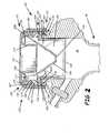
- FIG. 2is a fragmentary sectional view of an exemplary trocar system having first and second valves taken along line 1 - 1 of FIG. 1 ;
- FIG. 3is a side elevational view of an exemplary trocar system
- FIG. 4is a top plan view of a cap assembly of an exemplary trocar system
- FIG. 5is an exploded view of a cap assembly of an exemplary trocar system
- FIG. 6is a perspective view of a valve of an exemplary trocar system
- FIG. 7is a top plan view of a valve of an exemplary trocar system
- FIG. 8is a bottom plan view of a valve of an exemplary trocar system
- FIG. 9is sectional view of a valve of an exemplary trocar system taken along line 9 - 9 of FIG. 8 ;
- FIG. 10is an environmental perspective view of an exemplary valve, valve mold, and a slab illustrating the formation of a valve
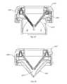
- FIG. 11is a side perspective view of a sealing gland according to an embodiment of the present invention.
- FIG. 12is a top perspective view of a sealing gland according to an embodiment of the present invention.
- FIG. 13is a side elevational view of a sealing gland according to an embodiment of the present invention.
- FIG. 14is a top plan view of a sealing gland illustrating symmetrical spacing of the slits in three valves according to an embodiment of the present invention
- FIG. 15is an exploded view of a sealing gland comprising three slitted valves according to an embodiment of the present invention.
- FIG. 16is a perspective view of a slitted valve according to an embodiment of the present invention.
- FIG. 17is a top plan view of a slitted valve according to an embodiment of the present invention.
- FIG. 18is a side elevational view of a slitted valve according to an embodiment of the present invention.
- FIG. 19is a perspective view of a slitted valve having a deformed shape according to an embodiment of the present invention.
- FIG. 20is a perspective view of a slitted valve according to an embodiment of the present invention.
- FIG. 21is a side elevational view of a slitted valve according to an embodiment of the present invention.
- FIG. 22is a fragmentary perspective view of a cap assembly according to an embodiment of the present invention.
- FIG. 23is a fragmentary perspective view of a cap assembly taken along the 23 - 23 line of FIG. 22 according to an embodiment of the present invention
- FIG. 24is an exploded view of a cap assembly of a trocar system according to an embodiment of the present invention.
- FIG. 25is an exploded view of a cap assembly of a trocar system according to an embodiment of the present invention.
- FIG. 26is a top perspective view of a sealing gland showing a closed stage opening according to an embodiment of the present invention.
- FIG. 27is a top perspective view of a sealing gland showing a first stage opening according to an embodiment of the present invention.
- FIG. 28is a top perspective view of a sealing gland showing a medium stage opening according to an embodiment of the present invention.
- FIG. 29is a top perspective view of a sealing gland showing a maximum stage opening according to an embodiment of the present invention.
- trocar system 120For clarity and simplicity, because the improvements and inventive elements presented herein, such as and without limitation opening flexible valve or sealing gland 250 , 250 ′, are operatively related and configured for preferred utilization with exemplary trocar system 120 , as shown in FIGS. 1-10 , a brief description of trocar system 120 follows, whereafter components common to previously described trocar system 120 , such as cannula 40 , and the improvements and inventive elements presented herein, will retain their original numbering. Those components not common will be renumbered accordingly.
- Previously described trocar system 120employs a nonplanar valve 150 which can be used with the cannula 40 .
- exemplary trocar system 120includes a plurality of tools 22 , 23 , 24 , 25 , each having an elongate body for extending through cap assembly 130 and cannula 40 , and each having a different diameter in the range of from about 4 millimeters to about 13 millimeters.
- the toolscan be obturators or other endoscopic related tools for various endoscopic procedures.
- Cap assembly 130 of trocar system 120includes valve housing 132 , which can have, for example, a substantially annular shape, can include proximal end housing portion 171 , distal end housing portion 173 , and medial housing portion 175 connected to and extending therebetween, as shown in FIG. 2 .
- Proximal end housing portion 171can include first opening 131 having a first opening diameter defined by portions of inner valve housing sidewall 177 extending distally in a substantially axial direction.
- Inner valve housing sidewall 177 forming first opening 131extends substantially axially downward toward valve opening 151 of valve 150 , described below.
- first opening 131can be rounded so as not to have any right angle edges at first opening 131 , but with the resulting cross-section forming substantially cylindrical first opening 131 extending along the same axis as that for valve opening 151 .
- Proximal end housing portion 171can also include annular valve ring recess 179 for retaining valve 150 .
- Distal end housing portion 173can include second opening 133 having a second opening diameter defined by distal valve housing sidewall 181 extending in a substantially axial direction.
- Medial housing portion 175can include first proximal valve housing inner perimeter surface 183 and second distal valve housing inner perimeter surface 185 which can have a perimeter size or circumference the same or slightly larger than that of first proximal valve housing inner perimeter surface 183 .
- exemplary valve 150can include valve body 155 positioned at least partially within valve housing 132 , axially aligned with first opening 131 of valve housing 132 , wherein valve body 155 includes proximal valve section 191 fixedly positioned entirely within valve housing 132 and distal valve section 193 extending axially from proximal valve section 191 .
- Proximal valve section 191includes valve ring 195 positioned in valve ring recess 179 ( FIG. 2 ) of valve housing 132 .
- Valve ring 195has proximal surface 197 , distal surface 199 , inner perimeter surface 201 , and outer perimeter surface 203 defining an outer perimeter of valve body 155 .
- Proximal valve section 191also can include plurality of convolutes 158 each having first sidewall 207 extending radially inwardly from a portion of inner perimeter surface 201 of valve ring 195 and second sidewall 209 extending axially from first sidewall 207 substantially parallel to or slightly angled from inner perimeter surface 201 of valve ring 195 and forming an inner radial periphery of proximal valve section 191 .
- Inner perimeter surface 201 of valve ring 195 , first sidewall 207 , and second sidewall 209 of each of plurality of convolutes 158form a respective convolute recess 211 .
- Proximal valve section 191can also include a plurality of rib members 159 (see, e.g., FIG. 5 ), each radially extending substantially an entire distance between the inner radial periphery of proximal valve section 191 and inner perimeter surface 201 of valve ring 195 and symmetrically positioned spaced-apart from each other.
- Distal valve section 193can extend axially from proximal valve section 191 and can include valve extension 152 extending axially from plurality of convolutes 158 .
- Valve extension 152can have proximal end portion 212 substantially connected to a distal portion of each of the plurality of convolutes 158 , distal end portion 213 , and medial portion 215 connected to and extending therebetween.
- medial portion 215can have a substantially frustro-conical or other similar conical-form shape, as illustrated.
- Distal valve section 193includes valve opening 151 positioned in distal end portion 213 of valve extension 152 , which can have, for example, an annular shape.
- Valve opening 151is adapted to individually and separately receive therethrough any one of the plurality of different elongate tools 22 , 23 , 24 , 25 , each having a different diameter so that when any one of the plurality of elongate tools is positioned through valve opening 151 , a septum-type seal is maintained between peripheries of distal end portion 213 of valve extension 152 surrounding valve opening 151 and outer peripheries of any one of the plurality of elongate tools when extending therethrough.
- plurality of tools 22 , 23 , 24 , 25each have an elongate body for extending through valve housing 132 , valve opening 151 of valve 150 , and cannula 40 .
- each convolute 158is positioned between and connected to any two adjacent rib members 159 .
- each convolute 158can be in a selected biased position before and after each of the plurality of different elongate tools, individually and separately, extends through valve opening 151 .
- the combination of convolutes 158 and valve extension 152allow for axial movement of tools 22 , 23 , 24 , 25 , without a corresponding movement within valve opening 151 with respect to outer peripheries of the tools.
- Valve body 155in general, and the portion of valve extension 152 surrounding opening 151 , in particular, can be formed of a flexible material to provide the elastic range necessary to accommodate plurality of elongate tools 22 , 23 , 24 , 25 .
- Cap assembly 130can also include compression ring 136 positioned in valve housing 132 at a medially axial position between first and second openings 131 , 133 , of valve housing 132 , abuttingly contacting axially facing distal surface 199 of valve ring 195 .
- Compression ring 136includes compression ring opening 137 substantially aligned axially with first opening 131 of valve housing 132 to allow extension of the plurality of elongate tools therethrough.
- Compression ring opening 137can also be sized to allow at least portions of inner valve housing sidewall 177 and valve 150 to extend therethrough.
- Compression ring 136also includes outer perimeter surface 217 having a radial diameter sized so that compression ring 136 substantially abuttingly contacts the proximal valve housing inner perimeter surface 183 when positioned within valve housing 132 , and includes annular flange 219 extending into each one of the plurality of convolute recesses 211 .
- Compression ring 136is positioned to compress valve ring 195 against an axially facing inner surface and an axially facing shoulder of proximal end housing portion 171 of valve housing 132 which, together along with a portion of first proximal valve housing inner perimeter surface 183 of medial housing portion 175 , form valve ring recess 179 , and/or to compress valve ring 195 against first proximal valve housing inner perimeter surface 183 of medial housing portion 175 , to hold valve ring 195 in valve ring recess 179 to fixedly position valve 150 within valve housing 132 .
- compression ring 136is positioned so that proximal valve housing inner perimeter surface 183 , surfaces forming valve ring recess 179 , and annular flange 219 of compression ring 136 rigidly hold valve ring 195 within valve housing 132 .
- Annular flange 219 of compression ring 136can include plurality of notches 221 symmetrically positioned spaced-apart from each other so that each of notches 221 aligns with and receives a separate one of plurality of rib members 159 to thereby rotationally align compression ring 136 with valve ring 195 when positioned in contact therewith.
- annular flange 219can include a plurality of separate spaced apart flanges (not shown) having a gap between each pair of flanges defining notch 221 and aligned with plurality of remembers 159 to thereby enhance positioning of valve ring 195 .
- valve housing 132 and valve ring 195the axially facing inner surface of proximal end housing portion 171 of valve housing 132 can include one or more protuberances 205 extending at least partially along the length of valve ring recess 179 , and proximal surface 197 of valve ring 195 can include one or more recesses 206 or can deform to form recess 206 , as illustrated, to receive one or more protuberances 205 to thereby enhance positioning of valve ring 195 within valve housing 132 .
- Cap assembly 130can also include second valve 160 .
- Second valve 160is advantageously positioned adjacent second opening 133 of valve housing 132 , abuttingly contacting compression ring 139 .
- Second valve 160advantageously has annular flange portion 162 spaced axially from the valve ring of first valve 150 .
- Annular flange portion 162can have a radial diameter sized so that annular flange portion 162 substantially abuttingly contacts distal valve inner housing perimeter surface 185 and axially facing distal surface of compression ring 136 adjacent compression ring opening 137 to enhance the positioning of second valve 160 within valve housing 132 .
- Second valve 160includes second valve opening 223 positioned within annular flange portion 162 and, when positioned within valve housing 132 , is substantially aligned axially with first and second openings 131 , 133 , of valve housing 132 to allow extension of plurality of elongate tools 22 , 23 , 24 , 25 , therethrough.
- Annular-shaped sidewalls 164are connected to annular flange portion 162 and extend distally in a substantially axial direction when positioned in valve housing 132 . At least one pair of valve flaps 166 is connected to and extends inwardly from sidewalls 164 and flange portion 162 . Sidewalls 164 , for example, can extend distally of the end of valve housing 132 so that flange portion 162 retains only portions of valve 160 within valve housing 132 and yet slidably or in a spaced-apart relation have other portions which are positioned within proximal portion 48 of cannula body 42 .
- Second valve 160also advantageously can have ribs or rib members (not shown), e.g., formed integrally therewith as a single piece, and connected to sidewalls 164 to reduce drag, as will be understood by those skilled in the art. Second valve 160 can also be advantageously impregnated with a lubricant such as an oil material to enhance performance of the valve.
- Proximal surface of annular flange portion 162 of second valve 160can include an at least partially annular recess 227 or can deform to form recess 227 , as illustrated, to receive an at least partially annular protuberance 225 extending from a distal surface of compression ring 136 to thereby enhance positioning of second valve 160 at least partially within valve housing 132 .
- a distal surface of annular flange portion 162 of second valve 160can further include second valve annular-shaped recess 229 adapted to receive axially extending annular-shaped flange 272 of maximal portion 48 of cannula 40 to thereby enhance positioning of at least part of proximal portion 48 of cannula 40 within valve housing 132 .
- Cap assembly 130can also include cap seal ring 138 positioned at least partially within valve housing 132 and having axially extending flange 274 positioned to abuttingly contact a distal surface of annular flange portion 162 of second valve 160 when positioned in valve housing 132 .
- Cap seal ring 138can include plurality of radially extending flanges 135 , each adapted to engage outer peripheries of a separate one of the plurality of radially extending flanges 34 of cannula 40 to slidably detachably connect valve housing 132 to cannula 40 .
- Cannula 40can also include an annular shaped axially extending flange adapted to engage annular-shaped recess 229 of second valve 160 to thereby enhance positioning of cannula 40 securely against second valve 160 when positioned in engagement with radially extending flanges 135 of cap seal ring 138 .
- the preferred embodiment of the present inventionemploys a variable opening flexible valve or sealing gland 250 , 250 ′, which can be used with cannula 40 as a substitute for valve 150 with little modification to cap assembly 130 to allow positioning in valve (seal gland) housing 132 .
- a variable opening flexible valve or sealing gland 250 , 250 ′which can be used with cannula 40 as a substitute for valve 150 with little modification to cap assembly 130 to allow positioning in valve (seal gland) housing 132 .
- components common to both the exemplary trocar system 120 described with reference to FIGS. 1-10such as cannula 40 , and the preferred incorporated use of the present invention that will be described will retain their original numbering. Those components not common will be renumbered accordingly.
- sealing gland 250see, e.g., FIGS. 11-15
- sealing gland 250 ′see, e.g., FIGS. 22-25
- sealing gland 250will primarily refer to sealing gland 250 for simplicity.
- the differences between sealing gland 250 and sealing gland 250 ′will be described later. Items common to both sealing gland 250 and sealing gland 250 ′ will retain the same numerical identifiers.
- sealing gland 250can include a plurality of valve body sections 255 (see, e.g., FIGS. 12 and 15 - 19 ).
- Valve body sections 255can include a silicon material coated with paralene to enhance flexibility and/or include others known to those skilled in the art.
- each valve body section 255has first valve section 291 including annular shaped valve ring 295 , second valve section 293 extending from first valve section 291 and including valve extension 252 having proximal end portion 312 , distal end portion 313 , and substantially conically shaped medial portion 315 connected to and extending therebetween.
- Valve opening 251 in distal end portion 313 of valve extension 252is adapted to receive therethrough an elongate tool such as, for example, tools 22 , 23 , 24 , 25 (see, e.g., FIG. 1 ).
- Slit 316 in each valve body section 255can extend between valve opening 251 and valve ring 295 , completely separating valve body section 255 in valve ring 295 .
- slit 316is aligned with the longitudinal axis of valve body section 255 .
- the portion of slit 316 extending through valve ring 295is arcuate, angled, or otherwise shaped to enhance interface within valve housing 132 .
- FIG. 19shows single valve body section 255 deformed to enhance interweaving with other valve body sections 255 and illustrating the extent of slit 316 .
- FIG. 15illustrates three valve body sections 255 deformed to allow interweaving of valve body sections 255 , deforming the seal gland shown in FIGS. 11-14 .
- each of the valve rings 295 of each of the valve body sections 255abuttingly contact one or both of the other of the valve rings 295 along their proximal and distal facing surfaces.
- This interweaving of valve rings 295forms a layered cap assembly valve ring 318 , as perhaps best illustrated in FIGS. 11 and 13 .
- valve body sections 255can be positioned so that slits 316 are evenly spaced. In this illustrated example utilizing three valve body sections 255 , slits 316 are spaced 120 degrees apart. Valve extensions 252 , however, rather than being securely connected, are in sliding contact with valve extension 252 of one or both of the other valve body sections 255 to form an interweaved valve extension 347 . That is, as perhaps best shown sequentially in FIGS.
- valve body sections 255form a substantially conically shaped iris diaphragm portion of sealing gland 250 which can flexibly adjust the size of iris 349 between the closed position ( FIG. 26 ) and the fully open position ( FIG. 29 ).
- expansion of the size of iris 349is in response to insertion of a tool such as, for example, tool 22 , 23 , 24 , 25 .
- a toolsuch as, for example, tool 22 , 23 , 24 , 25 .
- such conical iris-type designallows sealing gland 250 to be flexible and deformable, thus allowing the center opening of iris 349 to move laterally without loss of sealing when a medical instrument or tool is inserted through cannula 40 .
- valve rings 295can include a plurality of spaced apart recesses 343 extending through the proximal or distal surfaces.
- at least a portion of the recesses 345 of each valve ring 295can receive ultraviolet bonding agent.
- layered cap assembly valve ring 318is clamped between distal facing surfaces 179 and inner perimeter surface 183 of housing 132 by compression ring 236 (see FIGS.
- Compression ring 236includes a plurality of spaced apart pins 345 extending proximate a surface.
- recesses 343are positioned to receive plurality of spaced apart pins 345 to thereby further immobilize valve ring 295 of each one of valve body sections 255 , 255 ′ with respect to valve ring 295 of each other of the plurality of valve body sections 255 , 255 ′.
- proximal end portion 312 of second valve section 293 of each of valve body sections 255includes plurality of convolutes 258 , e.g., three, each having first sidewall 307 (best illustrated in FIG. 19 ) extending radially inwardly from a portion of the inner perimeter surface of valve ring 295 and second sidewall 309 extending axially from first sidewall 307 and forming an inner radial periphery of proximal end portion 312 of second valve section 293 .
- valve ring 295 , first sidewall 307 , and second sidewall 309 of each convolute 258form a respective convolute recess 311 for each convolute 258 .
- the plurality of convolutes 258are biased so that distal end portion 313 of the respective valve extension 252 is substantially inline with a central axis of a bore of valve/seal gland housing 132 , 132 ′ (see, e.g., FIGS. 2 , 22 , 23 ) without imparting a significant transverse force when an elongate tool is extended through the iris 349 .
- Each of the convolutes 258 for each proximal end portion of the second valve section of each of the plurality of valve body sections 255can be positioned between and connected to two adjacent rib members 259 (perhaps best illustrated in FIG. 17 ). Rib members 259 can function to reinforce movement and deformation recovery of convolutes 258 so that iris 349 formed by valve openings 251 of each of the valve body sections 255 can move transverse to the longitudinal axis of the valve without loss of sealing when an elongate tool is positioned therethrough.
- the proximal end portion of the second valve section of each of the plurality of valve body sections 255 ′includes a plurality of radial extensions 258 ′, each having first sidewall 307 ′ extending radially inwardly from a portion of the inner perimeter surface of valve ring 295 and second sidewall 309 ′ extending axially from first sidewall 307 approximately parallel to the inner perimeter surface of sealing gland housing 132 ′ (see, e.g., FIGS. 22-25 ) and forming an inner radial periphery of the proximal end portion of the second valve section.
- Plurality of radial extensions 258 ′are biased so that the distal end portion of the respective valve extension 252 ′ is substantially in-line with a central axis of a bore of sealing gland housing 132 ′ without imparting a significant transverse force when an elongate tool is extended through the iris 349 .
- the proximal end portion of the second valve section of each of the plurality of valve body sections 255 ′each can include a plurality of rib members 259 ′, each radially extending substantially an entire distance between the inner radial periphery of the proximal end portion of the second valve section and the inner perimeter surface of the valve ring 295 and, for example, symmetrically positioned spaced-apart from each other, e.g., 120 degrees in this illustration.
- the plurality of rib members 259 ′are positioned to bias valve extension 252 ′ of each valve body section 255 ′ so that the distal end portion of the respective valve extension 252 ′ is substantially in-line with a central axis of a bore of sealing gland housing 132 ′.
- Embodiments of the present inventionalso include a method of forming sealing gland 250 , 250 ′, for a cap assembly of cannula 40 .
- the methodcan include forming plurality of valve body sections 255 , 255 ′, each having a first valve section including annular shaped valve ring 295 , a second valve section extending from the first valve section and including valve extension 252 , 252 ′, having a proximal end portion, a distal end portion, and a substantially conically shaped medial portion connected to and extending therebetween.
- Valve opening 251can be positioned in the distal end portion of valve extension 252 , 252 ′, and is adapted to receive therethrough an elongate tool.
- the methodalso includes forming slit 316 in the each of the plurality of valve body sections 255 , 255 ′, extending between the respective valve opening 251 and the respective valve ring 295 , and positioning each one of valve rings 295 of each of valve body sections 255 , 255 ′, in abutting contact with the other valve rings 295 to form layered cap assembly valve ring 318 .
- the combination of valve body sections 255 , 255 ′form sealing gland 250 , 250 ′.
- valve ring 295 of each of the plurality of valve body sections 255 , 255includes plurality of spaced apart recesses 343 extending longitudinally through valve ring 295 .
- the methodcan further include the step of clamping sealing gland 250 , 250 ′ between the sealing gland housing (see, e.g., FIGS. 22 and 23 ) and compression ring to 36 having a corresponding plurality of spaced apart pins 345 positioned to extend through the plurality of spaced apart recesses 343 to immobilize valve ring 295 while allowing at least portions of valve extension 252 , 252 ′ to remain laterally movable.
Landscapes
- Health & Medical Sciences (AREA)
- Surgery (AREA)
- Life Sciences & Earth Sciences (AREA)
- Biomedical Technology (AREA)
- Nuclear Medicine, Radiotherapy & Molecular Imaging (AREA)
- Engineering & Computer Science (AREA)
- Pathology (AREA)
- Heart & Thoracic Surgery (AREA)
- Medical Informatics (AREA)
- Molecular Biology (AREA)
- Animal Behavior & Ethology (AREA)
- General Health & Medical Sciences (AREA)
- Public Health (AREA)
- Veterinary Medicine (AREA)
- Surgical Instruments (AREA)
Abstract
Description
Claims (10)
Priority Applications (1)
| Application Number | Priority Date | Filing Date | Title |
|---|---|---|---|
| US11/985,265US7798991B2 (en) | 2006-11-14 | 2007-11-14 | Trocar and cannula assembly having variable opening sealing gland and related methods |
Applications Claiming Priority (2)
| Application Number | Priority Date | Filing Date | Title |
|---|---|---|---|
| US86582406P | 2006-11-14 | 2006-11-14 | |
| US11/985,265US7798991B2 (en) | 2006-11-14 | 2007-11-14 | Trocar and cannula assembly having variable opening sealing gland and related methods |
Publications (2)
| Publication Number | Publication Date |
|---|---|
| US20080161758A1 US20080161758A1 (en) | 2008-07-03 |
| US7798991B2true US7798991B2 (en) | 2010-09-21 |
Family
ID=39585019
Family Applications (1)
| Application Number | Title | Priority Date | Filing Date |
|---|---|---|---|
| US11/985,265Active2028-02-08US7798991B2 (en) | 2006-11-14 | 2007-11-14 | Trocar and cannula assembly having variable opening sealing gland and related methods |
Country Status (1)
| Country | Link |
|---|---|
| US (1) | US7798991B2 (en) |
Cited By (10)
| Publication number | Priority date | Publication date | Assignee | Title |
|---|---|---|---|---|
| US20090157006A1 (en)* | 2007-12-13 | 2009-06-18 | Medical Components, Inc | Introducer Assembly with Cap and Method of using Same |
| US8771230B2 (en) | 2010-05-19 | 2014-07-08 | Tangent Medical Technologies, Llc | Integrated vascular delivery system |
| US8814833B2 (en) | 2010-05-19 | 2014-08-26 | Tangent Medical Technologies Llc | Safety needle system operable with a medical device |
| US9161839B2 (en) | 2008-12-04 | 2015-10-20 | Pivot Medical, Inc. | Method and apparatus for accessing the interior of a hip joint, including the provision and use of a novel telescoping access cannula and a novel telescoping obturator |
| US9427257B2 (en) | 2014-07-08 | 2016-08-30 | Applied Medical Resources Corporation | Highly responsive instrument seal |
| US20170065788A1 (en)* | 2015-09-08 | 2017-03-09 | Jeng-Yu Chou | Medical joint and check valve module thereof |
| US9592366B2 (en) | 2009-08-14 | 2017-03-14 | The Regents Of The University Of Michigan | Integrated vascular delivery system |
| US10086170B2 (en) | 2014-02-04 | 2018-10-02 | Icu Medical, Inc. | Self-priming systems and methods |
| USD956219S1 (en) | 2020-07-10 | 2022-06-28 | Covidien Lp | Port apparatus |
| USD963851S1 (en) | 2020-07-10 | 2022-09-13 | Covidien Lp | Port apparatus |
Families Citing this family (19)
| Publication number | Priority date | Publication date | Assignee | Title |
|---|---|---|---|---|
| US7785294B2 (en)* | 2003-09-30 | 2010-08-31 | Ethicon Endo-Surgery, Inc. | Woven protector for trocar seal assembly |
| EP2117630A4 (en)* | 2007-02-20 | 2013-08-07 | Covidien Lp | Flexible external cannula sheath |
| WO2009086505A2 (en)* | 2007-12-27 | 2009-07-09 | University Of South Florida | Multichannel trocar |
| US20100114033A1 (en)* | 2008-11-06 | 2010-05-06 | Tyco Healthcare Group Lp | Surgical access device |
| CN101480354A (en)* | 2009-01-23 | 2009-07-15 | 周星 | Tank-type general purpose type radial seal ring for puncture outfit and puncture outfit |
| US8628056B2 (en)* | 2009-02-02 | 2014-01-14 | Aptargroup, Inc. | Dual sealing system for use with a probe |
| USD619716S1 (en)* | 2009-05-18 | 2010-07-13 | Karl Storz Gmbh & Co. Kg | Trocar |
| ITRM20110169A1 (en)* | 2011-04-01 | 2012-10-02 | Mysui S R L | HOLDING DEVICE FOR TROCAR AND RELATED TROCAR. |
| US9737686B2 (en)* | 2012-03-12 | 2017-08-22 | Becton, Dickinson And Company | Catheter adapter port valve |
| CA2879636C (en)* | 2012-09-28 | 2020-06-09 | Covidien Lp | Optical trocar visualization system and apparatus |
| CN104095672B (en)* | 2013-04-15 | 2019-04-30 | 广州迪克医疗器械有限公司 | A kind of universal sealing ring and puncture device |
| DE102014103508B4 (en)* | 2014-03-14 | 2019-04-18 | Fresenius Medical Care Deutschland Gmbh | Tensioned valve for medical functional device, and medical functional device |
| EP3294161B1 (en) | 2015-05-15 | 2021-03-10 | Covidien LP | Valve assembly for a surgical access device |
| US11413068B2 (en) | 2019-05-09 | 2022-08-16 | Covidien Lp | Seal assemblies for surgical access assemblies |
| US11812991B2 (en) | 2019-10-18 | 2023-11-14 | Covidien Lp | Seal assemblies for surgical access assemblies |
| US11642153B2 (en) | 2020-03-19 | 2023-05-09 | Covidien Lp | Instrument seal for surgical access assembly |
| US11541218B2 (en) | 2020-03-20 | 2023-01-03 | Covidien Lp | Seal assembly for a surgical access assembly and method of manufacturing the same |
| US11446058B2 (en) | 2020-03-27 | 2022-09-20 | Covidien Lp | Fixture device for folding a seal member |
| US11717321B2 (en) | 2020-04-24 | 2023-08-08 | Covidien Lp | Access assembly with retention mechanism |
Citations (38)
| Publication number | Priority date | Publication date | Assignee | Title |
|---|---|---|---|---|
| EP0066008A1 (en) | 1981-06-03 | 1982-12-08 | Siemens Aktiengesellschaft | X-ray diagnostic apparatus for angiographic examination |
| US4486024A (en) | 1983-05-17 | 1984-12-04 | Westinghouse Electric Corp. | Dual-ring gland seal for dynamoelectric machine rotor |
| EP0131349A1 (en) | 1983-06-13 | 1985-01-16 | Hewlett-Packard Company | Circuit testing utilizing data compression and derivative mode vectors |
| US4655752A (en)* | 1983-10-24 | 1987-04-07 | Acufex Microsurgical, Inc. | Surgical cannula |
| US4960412A (en)* | 1988-04-15 | 1990-10-02 | Universal Medical Instrument Corp. | Catheter introducing system |
| US5104383A (en) | 1989-10-17 | 1992-04-14 | United States Surgical Corporation | Trocar adapter seal and method of use |
| US5150702A (en) | 1990-06-18 | 1992-09-29 | Olympus Optical Co., Ltd. | Iris diaphragm device and endoscope having the same |
| US5209737A (en) | 1991-07-18 | 1993-05-11 | Applied Medical Resources, Inc. | Lever actuated septum seal |
| US5226891A (en) | 1992-04-07 | 1993-07-13 | Applied Medical Resources | Seal protection apparatus |
| US5342315A (en)* | 1993-04-12 | 1994-08-30 | Ethicon, Inc. | Trocar seal/protector assemblies |
| US5376077A (en) | 1992-12-04 | 1994-12-27 | Interventional Technologies, Inc. | Introducer sheath with seal protector |
| US5385552A (en)* | 1993-03-11 | 1995-01-31 | Habley Medical Technology Corporation | Trocar with overlapping seal elements |
| US5385553A (en) | 1991-07-18 | 1995-01-31 | Applied Medical Resources Corporation | Trocar with floating septum seal |
| US5411483A (en) | 1993-02-10 | 1995-05-02 | Origin Medsystems, Inc. | Gas-tight seal accommodating surgical instruments with a wide range of diameters |
| US5443452A (en) | 1992-07-02 | 1995-08-22 | Applied Medical Resources | Seal assembly for access device |
| US5449141A (en) | 1993-07-20 | 1995-09-12 | Fuller Company | Iris diaphragm valve |
| US5576792A (en) | 1995-05-19 | 1996-11-19 | Eastman Kodak Company | Method for assembling an iris diaphragm |
| US5603702A (en)* | 1994-08-08 | 1997-02-18 | United States Surgical Corporation | Valve system for cannula assembly |
| US5657963A (en) | 1993-06-16 | 1997-08-19 | United States Surgical Corporation | Seal assembly for accommodating introduction of surgical instruments |
| US5792113A (en) | 1996-12-12 | 1998-08-11 | Ethicon Endo-Surgerym Inc. | Universal seal for a trocar |
| US5827228A (en) | 1991-10-18 | 1998-10-27 | Ethicon, Inc. | Seal members for surgical trocars |
| US5923913A (en) | 1998-02-04 | 1999-07-13 | Eastman Kodak Company | Iris diaphragm |
| US5989224A (en) | 1998-02-23 | 1999-11-23 | Dexide Corporation | Universal seal for use with endoscopic cannula |
| USRE36702E (en) | 1993-07-14 | 2000-05-16 | United States Surgical Corporation | Seal assembly for accommodating introduction of surgical instruments |
| US6569119B1 (en) | 2000-01-26 | 2003-05-27 | Genicon, Lc | Trocar system having cannula with finger grips |
| US6569120B1 (en)* | 1991-10-18 | 2003-05-27 | United States Surgical Corporation | Seal assembly |
| US6632200B2 (en)* | 2000-01-25 | 2003-10-14 | St. Jude Medical, Daig Division | Hemostasis valve |
| US20030195472A1 (en)* | 1991-10-18 | 2003-10-16 | Green David T. | Valve assembly for introducing instruments into body cavities |
| US6702787B2 (en)* | 1997-05-02 | 2004-03-09 | Tyco Healthcare Group Lp | Trocar seal system |
| US20040230161A1 (en)* | 2003-03-21 | 2004-11-18 | Zeiner Mark S. | Trocar seal assembly |
| US20050131349A1 (en) | 2003-12-12 | 2005-06-16 | Applied Medical Resources Corporation | Shielded septum trocar seal |
| US20050165433A1 (en) | 2004-01-23 | 2005-07-28 | Haberland Gary W. | Trocar having planar fixed septum seal and related methods |
| US6980376B2 (en) | 2003-03-03 | 2005-12-27 | Leica Microsystems Wetzlar Gmbh | Iris diaphragm device |
| US20060027675A1 (en) | 2004-08-06 | 2006-02-09 | Brian Takeda | Disposable perforated straw |
| US20060047293A1 (en) | 2004-01-23 | 2006-03-02 | Haberland Gary W | Trocar having planar fixed septum seal and related methods |
| US7025747B2 (en)* | 2000-10-13 | 2006-04-11 | Tyco Healthcare Group Lp | Valve assembly including diameter reduction structure for trocar |
| US20060217665A1 (en)* | 2004-11-18 | 2006-09-28 | Laparoscopic Partners Llc | Surgical instrument seal assembly and triple lead thread |
| US20070185453A1 (en)* | 2003-03-21 | 2007-08-09 | Michael Cropper S | Conical trocar seal |
- 2007
- 2007-11-14USUS11/985,265patent/US7798991B2/enactiveActive
Patent Citations (42)
| Publication number | Priority date | Publication date | Assignee | Title |
|---|---|---|---|---|
| EP0066008A1 (en) | 1981-06-03 | 1982-12-08 | Siemens Aktiengesellschaft | X-ray diagnostic apparatus for angiographic examination |
| US5308336A (en) | 1982-09-28 | 1994-05-03 | Applied Medical Resources | Seal protection mechanism |
| US4486024A (en) | 1983-05-17 | 1984-12-04 | Westinghouse Electric Corp. | Dual-ring gland seal for dynamoelectric machine rotor |
| EP0131349A1 (en) | 1983-06-13 | 1985-01-16 | Hewlett-Packard Company | Circuit testing utilizing data compression and derivative mode vectors |
| US4655752A (en)* | 1983-10-24 | 1987-04-07 | Acufex Microsurgical, Inc. | Surgical cannula |
| US4960412A (en)* | 1988-04-15 | 1990-10-02 | Universal Medical Instrument Corp. | Catheter introducing system |
| US5104383A (en) | 1989-10-17 | 1992-04-14 | United States Surgical Corporation | Trocar adapter seal and method of use |
| US5150702A (en) | 1990-06-18 | 1992-09-29 | Olympus Optical Co., Ltd. | Iris diaphragm device and endoscope having the same |
| US5209737A (en) | 1991-07-18 | 1993-05-11 | Applied Medical Resources, Inc. | Lever actuated septum seal |
| US5385553A (en) | 1991-07-18 | 1995-01-31 | Applied Medical Resources Corporation | Trocar with floating septum seal |
| US5827228A (en) | 1991-10-18 | 1998-10-27 | Ethicon, Inc. | Seal members for surgical trocars |
| US6569120B1 (en)* | 1991-10-18 | 2003-05-27 | United States Surgical Corporation | Seal assembly |
| US20030195472A1 (en)* | 1991-10-18 | 2003-10-16 | Green David T. | Valve assembly for introducing instruments into body cavities |
| US5226891A (en) | 1992-04-07 | 1993-07-13 | Applied Medical Resources | Seal protection apparatus |
| US5443452A (en) | 1992-07-02 | 1995-08-22 | Applied Medical Resources | Seal assembly for access device |
| US5782812A (en) | 1992-07-02 | 1998-07-21 | Applied Medical Resources Corporation | Seal assembly for access device |
| US5376077A (en) | 1992-12-04 | 1994-12-27 | Interventional Technologies, Inc. | Introducer sheath with seal protector |
| US5411483A (en) | 1993-02-10 | 1995-05-02 | Origin Medsystems, Inc. | Gas-tight seal accommodating surgical instruments with a wide range of diameters |
| US5385552A (en)* | 1993-03-11 | 1995-01-31 | Habley Medical Technology Corporation | Trocar with overlapping seal elements |
| US5342315A (en)* | 1993-04-12 | 1994-08-30 | Ethicon, Inc. | Trocar seal/protector assemblies |
| US5657963A (en) | 1993-06-16 | 1997-08-19 | United States Surgical Corporation | Seal assembly for accommodating introduction of surgical instruments |
| USRE36702E (en) | 1993-07-14 | 2000-05-16 | United States Surgical Corporation | Seal assembly for accommodating introduction of surgical instruments |
| US5449141A (en) | 1993-07-20 | 1995-09-12 | Fuller Company | Iris diaphragm valve |
| US5603702A (en)* | 1994-08-08 | 1997-02-18 | United States Surgical Corporation | Valve system for cannula assembly |
| US5895377A (en) | 1994-08-08 | 1999-04-20 | United States Surgical Corporation | Valve system for cannula assembly |
| US5576792A (en) | 1995-05-19 | 1996-11-19 | Eastman Kodak Company | Method for assembling an iris diaphragm |
| US5792113A (en) | 1996-12-12 | 1998-08-11 | Ethicon Endo-Surgerym Inc. | Universal seal for a trocar |
| US6702787B2 (en)* | 1997-05-02 | 2004-03-09 | Tyco Healthcare Group Lp | Trocar seal system |
| US5923913A (en) | 1998-02-04 | 1999-07-13 | Eastman Kodak Company | Iris diaphragm |
| US5989224A (en) | 1998-02-23 | 1999-11-23 | Dexide Corporation | Universal seal for use with endoscopic cannula |
| US6551282B1 (en) | 1998-02-23 | 2003-04-22 | Tyco Healthcare Group Lp | Universal seal for use with endoscopic cannula |
| US6632200B2 (en)* | 2000-01-25 | 2003-10-14 | St. Jude Medical, Daig Division | Hemostasis valve |
| US6569119B1 (en) | 2000-01-26 | 2003-05-27 | Genicon, Lc | Trocar system having cannula with finger grips |
| US7025747B2 (en)* | 2000-10-13 | 2006-04-11 | Tyco Healthcare Group Lp | Valve assembly including diameter reduction structure for trocar |
| US6980376B2 (en) | 2003-03-03 | 2005-12-27 | Leica Microsystems Wetzlar Gmbh | Iris diaphragm device |
| US20040230161A1 (en)* | 2003-03-21 | 2004-11-18 | Zeiner Mark S. | Trocar seal assembly |
| US20070185453A1 (en)* | 2003-03-21 | 2007-08-09 | Michael Cropper S | Conical trocar seal |
| US20050131349A1 (en) | 2003-12-12 | 2005-06-16 | Applied Medical Resources Corporation | Shielded septum trocar seal |
| US20050165433A1 (en) | 2004-01-23 | 2005-07-28 | Haberland Gary W. | Trocar having planar fixed septum seal and related methods |
| US20060047293A1 (en) | 2004-01-23 | 2006-03-02 | Haberland Gary W | Trocar having planar fixed septum seal and related methods |
| US20060027675A1 (en) | 2004-08-06 | 2006-02-09 | Brian Takeda | Disposable perforated straw |
| US20060217665A1 (en)* | 2004-11-18 | 2006-09-28 | Laparoscopic Partners Llc | Surgical instrument seal assembly and triple lead thread |
Cited By (33)
| Publication number | Priority date | Publication date | Assignee | Title |
|---|---|---|---|---|
| US20090157006A1 (en)* | 2007-12-13 | 2009-06-18 | Medical Components, Inc | Introducer Assembly with Cap and Method of using Same |
| US11247024B2 (en) | 2007-12-13 | 2022-02-15 | Medical Components, Inc. | Introducer assembly with cap and method of using same |
| US9352129B2 (en)* | 2007-12-13 | 2016-05-31 | Medical Components, Inc. | Introducer assembly with cap and method of using same |
| US10328240B2 (en) | 2007-12-13 | 2019-06-25 | Medical Components, Inc. | Introducer assembly with cap and method of using same |
| US12171461B2 (en) | 2008-12-04 | 2024-12-24 | Stryker Corporation | Method and apparatus for accessing the interior of a hip joint, including the provision and use of a novel telescoping access cannula and a novel telescoping obturator |
| US11471188B2 (en) | 2008-12-04 | 2022-10-18 | Stryker Corporation | Method and apparatus for accessing the interior of a hip joint, including the provision and use of a novel telescoping access cannula and a novel telescoping obturator |
| US9161839B2 (en) | 2008-12-04 | 2015-10-20 | Pivot Medical, Inc. | Method and apparatus for accessing the interior of a hip joint, including the provision and use of a novel telescoping access cannula and a novel telescoping obturator |
| US10245070B2 (en) | 2008-12-04 | 2019-04-02 | Pivot Medical, Inc. | Method and apparatus for accessing the interior of a hip joint, including the provision and use of a novel telescoping access cannula and a novel telescoping obturator |
| US9592366B2 (en) | 2009-08-14 | 2017-03-14 | The Regents Of The University Of Michigan | Integrated vascular delivery system |
| US10668252B2 (en) | 2009-08-14 | 2020-06-02 | The Regents Of The University Of Michigan | Integrated vascular delivery system |
| US12370348B2 (en) | 2009-08-14 | 2025-07-29 | The Regents Of The University Of Michigan | Integrated vascular delivery system |
| US9962526B2 (en) | 2009-08-14 | 2018-05-08 | The Regents Of The University Of Michigan | Integrated vascular delivery system |
| US11577053B2 (en) | 2009-08-14 | 2023-02-14 | The Regents Of The University Of Michigan | Integrated vascular delivery system |
| US11577052B2 (en) | 2010-05-19 | 2023-02-14 | Tangent Medical Technologies, Inc. | Integrated vascular delivery system |
| US9308354B2 (en) | 2010-05-19 | 2016-04-12 | Tangent Medical Technologies Llc | Safety needle system operable with a medical device |
| US9827398B2 (en) | 2010-05-19 | 2017-11-28 | Tangent Medical Technologies, Inc. | Integrated vascular delivery system |
| US8771230B2 (en) | 2010-05-19 | 2014-07-08 | Tangent Medical Technologies, Llc | Integrated vascular delivery system |
| US12059538B2 (en) | 2010-05-19 | 2024-08-13 | Tangent Medical Technologies, Inc. | Safety needle system operable with a medical device |
| US10569057B2 (en) | 2010-05-19 | 2020-02-25 | Tangent Medical Technologies, Inc. | Integrated vascular delivery system |
| US8814833B2 (en) | 2010-05-19 | 2014-08-26 | Tangent Medical Technologies Llc | Safety needle system operable with a medical device |
| US10159818B2 (en) | 2010-05-19 | 2018-12-25 | Tangent Medical Technologies, Inc. | Safety needle system operable with a medical device |
| US10905858B2 (en) | 2010-05-19 | 2021-02-02 | Tangent Medical Technologies, Inc. | Safety needle system operable with a medical device |
| US10814107B2 (en) | 2014-02-04 | 2020-10-27 | Icu Medical, Inc. | Self-priming systems and methods |
| US10086170B2 (en) | 2014-02-04 | 2018-10-02 | Icu Medical, Inc. | Self-priming systems and methods |
| US11724071B2 (en) | 2014-02-04 | 2023-08-15 | Icu Medical, Inc. | Self-priming systems and methods |
| US9724125B2 (en) | 2014-07-08 | 2017-08-08 | Applied Medical Resources Corporation | Highly responsive instrument seal |
| US10492828B2 (en) | 2014-07-08 | 2019-12-03 | Applied Medical Resources Corporation | Highly responsive instrument seal |
| US9427257B2 (en) | 2014-07-08 | 2016-08-30 | Applied Medical Resources Corporation | Highly responsive instrument seal |
| US10086164B2 (en)* | 2015-09-08 | 2018-10-02 | Jeng-Yu Chou | Medical joint and check valve module thereof |
| US20170065788A1 (en)* | 2015-09-08 | 2017-03-09 | Jeng-Yu Chou | Medical joint and check valve module thereof |
| USD956219S1 (en) | 2020-07-10 | 2022-06-28 | Covidien Lp | Port apparatus |
| USD963851S1 (en) | 2020-07-10 | 2022-09-13 | Covidien Lp | Port apparatus |
| USD1035870S1 (en) | 2020-07-10 | 2024-07-16 | Covidien Lp | Port apparatus |
Also Published As
| Publication number | Publication date |
|---|---|
| US20080161758A1 (en) | 2008-07-03 |
Similar Documents
| Publication | Publication Date | Title |
|---|---|---|
| US7798991B2 (en) | Trocar and cannula assembly having variable opening sealing gland and related methods | |
| US7585288B2 (en) | Trocar and cannula assembly having conical valve and related methods | |
| US7842013B2 (en) | Trocar and cannula assembly having conical valve and related methods | |
| US8454563B2 (en) | Trocar and cannula assembly having improved conical valve, and methods related thereto | |
| US5300033A (en) | Introducer assembly and valve construction for use therein | |
| US6860463B2 (en) | Access valve | |
| JP6684285B2 (en) | Cannula seal | |
| US11679248B2 (en) | Pressure activated valve for high flow rate and pressure venous access applications | |
| US20060047293A1 (en) | Trocar having planar fixed septum seal and related methods | |
| JP2957134B2 (en) | Valve and valved trocar mantle | |
| US5514098A (en) | Caps for sealing a cannula assembly | |
| US8292854B2 (en) | Access assembly with ribbed seal | |
| US5350364A (en) | Universal seal for trocar assembly | |
| US8262622B2 (en) | Surgical gel seal | |
| US8147457B2 (en) | Conical trocar seal | |
| US9017252B2 (en) | Access assembly with flexible cannulas | |
| US6086570A (en) | Hemostasis valve with membranes having offset apertures | |
| JPH10502841A (en) | Multiport trocar | |
| US20120245527A1 (en) | Introducer valve | |
| ITRM20110169A1 (en) | HOLDING DEVICE FOR TROCAR AND RELATED TROCAR. | |
| US20190142462A1 (en) | Trocar seal membrane comprising multi-dimensional floating pleats | |
| US20050165433A1 (en) | Trocar having planar fixed septum seal and related methods | |
| CN111246814B (en) | Device for performing minimally invasive surgery with bellows support housing | |
| EP3015083B1 (en) | Sealing device for sealing a feedthrough for a medical instrument | |
| JP2021041147A (en) | Centering mechanisms for surgical access assembly |
Legal Events
| Date | Code | Title | Description |
|---|---|---|---|
| STCF | Information on status: patent grant | Free format text:PATENTED CASE | |
| AS | Assignment | Owner name:SLAD HEALTHCARE S.P.A., ITALY Free format text:SECURITY AGREEMENT;ASSIGNOR:GENICO, INC.;REEL/FRAME:029126/0531 Effective date:20120727 | |
| AS | Assignment | Owner name:GENICO, INC., FLORIDA Free format text:RELEASE AND SATISFACTION OF SECURITY AGREEMENT;ASSIGNOR:SIAD HEALTHCARE S.P.A.;REEL/FRAME:030902/0461 Effective date:20130401 | |
| REMI | Maintenance fee reminder mailed | ||
| FPAY | Fee payment | Year of fee payment:4 | |
| SULP | Surcharge for late payment | ||
| AS | Assignment | Owner name:GENICON, LLC, FLORIDA Free format text:MERGER;ASSIGNOR:GENICO, INC;REEL/FRAME:033593/0729 Effective date:20121228 | |
| AS | Assignment | Owner name:GENICON, INC., FLORIDA Free format text:ASSIGNMENT OF ASSIGNORS INTEREST;ASSIGNOR:GENICON, LLC;REEL/FRAME:033675/0374 Effective date:20140825 | |
| MAFP | Maintenance fee payment | Free format text:PAYMENT OF MAINTENANCE FEE, 8TH YR, SMALL ENTITY (ORIGINAL EVENT CODE: M2552) Year of fee payment:8 | |
| AS | Assignment | Owner name:KARL STORZ ENDOVISION, INC., MASSACHUSETTS Free format text:ASSIGNMENT OF ASSIGNORS INTEREST;ASSIGNOR:GENICON, INC.;REEL/FRAME:054768/0362 Effective date:20201215 | |
| FEPP | Fee payment procedure | Free format text:ENTITY STATUS SET TO UNDISCOUNTED (ORIGINAL EVENT CODE: BIG.); ENTITY STATUS OF PATENT OWNER: LARGE ENTITY | |
| MAFP | Maintenance fee payment | Free format text:PAYMENT OF MAINTENANCE FEE, 12TH YEAR, LARGE ENTITY (ORIGINAL EVENT CODE: M1553); ENTITY STATUS OF PATENT OWNER: LARGE ENTITY Year of fee payment:12 |