US7798954B2 - Hydraulic gastric band with collapsible reservoir - Google Patents
Hydraulic gastric band with collapsible reservoirDownload PDFInfo
- Publication number
- US7798954B2 US7798954B2US11/754,091US75409107AUS7798954B2US 7798954 B2US7798954 B2US 7798954B2US 75409107 AUS75409107 AUS 75409107AUS 7798954 B2US7798954 B2US 7798954B2
- Authority
- US
- United States
- Prior art keywords
- fluid
- band
- reservoir
- pressure
- fill tube
- Prior art date
- Legal status (The legal status is an assumption and is not a legal conclusion. Google has not performed a legal analysis and makes no representation as to the accuracy of the status listed.)
- Expired - Fee Related, expires
Links
Images


Classifications
- A—HUMAN NECESSITIES
- A61—MEDICAL OR VETERINARY SCIENCE; HYGIENE
- A61F—FILTERS IMPLANTABLE INTO BLOOD VESSELS; PROSTHESES; DEVICES PROVIDING PATENCY TO, OR PREVENTING COLLAPSING OF, TUBULAR STRUCTURES OF THE BODY, e.g. STENTS; ORTHOPAEDIC, NURSING OR CONTRACEPTIVE DEVICES; FOMENTATION; TREATMENT OR PROTECTION OF EYES OR EARS; BANDAGES, DRESSINGS OR ABSORBENT PADS; FIRST-AID KITS
- A61F5/00—Orthopaedic methods or devices for non-surgical treatment of bones or joints; Nursing devices ; Anti-rape devices
- A61F5/0003—Apparatus for the treatment of obesity; Anti-eating devices
- A—HUMAN NECESSITIES
- A61—MEDICAL OR VETERINARY SCIENCE; HYGIENE
- A61B—DIAGNOSIS; SURGERY; IDENTIFICATION
- A61B5/00—Measuring for diagnostic purposes; Identification of persons
- A61B5/0002—Remote monitoring of patients using telemetry, e.g. transmission of vital signals via a communication network
- A61B5/0031—Implanted circuitry
- A—HUMAN NECESSITIES
- A61—MEDICAL OR VETERINARY SCIENCE; HYGIENE
- A61B—DIAGNOSIS; SURGERY; IDENTIFICATION
- A61B5/00—Measuring for diagnostic purposes; Identification of persons
- A61B5/03—Measuring fluid pressure within the body other than blood pressure, e.g. cerebral pressure ; Measuring pressure in body tissues or organs
- A61B5/036—Measuring fluid pressure within the body other than blood pressure, e.g. cerebral pressure ; Measuring pressure in body tissues or organs by means introduced into body tracts
- A—HUMAN NECESSITIES
- A61—MEDICAL OR VETERINARY SCIENCE; HYGIENE
- A61B—DIAGNOSIS; SURGERY; IDENTIFICATION
- A61B5/00—Measuring for diagnostic purposes; Identification of persons
- A61B5/41—Detecting, measuring or recording for evaluating the immune or lymphatic systems
- A61B5/411—Detecting or monitoring allergy or intolerance reactions to an allergenic agent or substance
- A—HUMAN NECESSITIES
- A61—MEDICAL OR VETERINARY SCIENCE; HYGIENE
- A61F—FILTERS IMPLANTABLE INTO BLOOD VESSELS; PROSTHESES; DEVICES PROVIDING PATENCY TO, OR PREVENTING COLLAPSING OF, TUBULAR STRUCTURES OF THE BODY, e.g. STENTS; ORTHOPAEDIC, NURSING OR CONTRACEPTIVE DEVICES; FOMENTATION; TREATMENT OR PROTECTION OF EYES OR EARS; BANDAGES, DRESSINGS OR ABSORBENT PADS; FIRST-AID KITS
- A61F5/00—Orthopaedic methods or devices for non-surgical treatment of bones or joints; Nursing devices ; Anti-rape devices
- A61F5/0003—Apparatus for the treatment of obesity; Anti-eating devices
- A61F5/0013—Implantable devices or invasive measures
- A61F5/005—Gastric bands
- A61F5/0053—Gastric bands remotely adjustable
- A—HUMAN NECESSITIES
- A61—MEDICAL OR VETERINARY SCIENCE; HYGIENE
- A61B—DIAGNOSIS; SURGERY; IDENTIFICATION
- A61B17/00—Surgical instruments, devices or methods
- A61B17/12—Surgical instruments, devices or methods for ligaturing or otherwise compressing tubular parts of the body, e.g. blood vessels or umbilical cord
- A61B17/132—Tourniquets
- A61B17/135—Tourniquets inflatable
- A61B17/1355—Automated control means therefor
- A—HUMAN NECESSITIES
- A61—MEDICAL OR VETERINARY SCIENCE; HYGIENE
- A61B—DIAGNOSIS; SURGERY; IDENTIFICATION
- A61B2562/00—Details of sensors; Constructional details of sensor housings or probes; Accessories for sensors
- A61B2562/02—Details of sensors specially adapted for in-vivo measurements
- A61B2562/0247—Pressure sensors
- A—HUMAN NECESSITIES
- A61—MEDICAL OR VETERINARY SCIENCE; HYGIENE
- A61B—DIAGNOSIS; SURGERY; IDENTIFICATION
- A61B2562/00—Details of sensors; Constructional details of sensor housings or probes; Accessories for sensors
- A61B2562/04—Arrangements of multiple sensors of the same type
- A61B2562/043—Arrangements of multiple sensors of the same type in a linear array
Definitions
- the present inventionrelates, in general, to devices and methods for controlling obesity, and, more particularly, a gastric band or gastric band assembly/system, and corresponding methods, configured for self-monitoring and adjustment of the size, i.e., internal diameter, of the gastric band so as to provide ongoing adjustment of stoma size in a patient.
- a gastric band or gastric band assembly/systemconfigured for self-monitoring and adjustment of the size, i.e., internal diameter, of the gastric band so as to provide ongoing adjustment of stoma size in a patient.
- Gastrointestinal surgeryis used by physicians to treat people who are severely obese and cannot lose weight by traditional means or who suffer from serious obesity-related health problems.
- gastrointestinal surgerypromotes weight loss by restricting food intake, and more specifically, restrictive operations limit food intake by creating a narrow passage or “stoma” from the upper part of the stomach into the larger lower part, which reduces the amount of food the stomach can hold and slows the passage of food through the stomach.
- the stomawas of a fixed size, but physicians have more recently determined that the procedure is more effective if the stoma can be adjusted to alter its size.
- AGBadjustable gastric banding
- a hollow bandi.e., a gastric band
- silicone elastomeris placed around the stomach near its upper end, creating a small pouch and a narrow passage (i.e., a stoma) into the rest of the stomach.
- the bandis then inflated with a saline solution by using a non-coring needle and syringe to access a small port that is placed under the skin.
- the gastric bandcan be tightened or loosened over time by the physician or another technician extracorporeally by increasing or decreasing the amount of saline solution in the band via the access port to change the size of the passage or stoma.
- gastric bandshave been developed to allow a physician or other technician to adjust an implanted gastric band.
- these band systemsinclude a sensor for measuring or determining parameters associated with the patient and in response, the physician or technician acts to adjust the volume of fluid in the band based on the patient parameters.
- one adjustable gastric band systemdetermines when the pressure in a patient's stomach exceeds a pre-set limit and provides an alarm to an external control device.
- a doctor or other operatorthen responds by loosening the gastric band by removing an amount of fluid from the band via the external access port and fill line.
- components for adjusting the size of the gastric bandare implanted within the patient, and when a physical parameter related to the patient, such as stomach pressure or the physical position of the patient, are determined, an external control unit outside the patient's body is operated to power the implanted components to adjust the size of the band, e.g., by adding or removing a preset volume of fluid from the band.
- the existing gastric bandsdo not meet the needs of patients.
- the deficiencies in the existing adjustable gastric bandsare due to the need for the patient to be treated by a doctor or other technician to adjust the size of the gastric band and the formed stoma via an external control unit.
- Other deficienciesare related to the unreliability or inaccuracy of sensing parameters related to the patient and correlating this to a desired stoma size.
- some of the existing gastric bandsrequire insertion of sensors into the patient, such as into or onto the stomach to determine stomach pressure. Due to these and other limitations of existing technologies, there remains a need for an improved gastric banding system, and associated adjustment methods, for providing improved adjustments to the size of a stoma in a patient being treated for obesity.
- the present inventionaddresses the above and other problems by providing a self-regulating gastric band system for implanting in an obese patient to automatically adjust the size of a stoma on a periodic or ongoing basis.
- the systemis “self-regulating” in some embodiments as it includes a sensor for sensing a property or parameter of an implanted expandable gastric band and a band adjustment assembly or system that adjusts the size of the expandable gastric band in response to the sensed band property.
- a physician or clinicianmay set an operating range for the property in memory of the system prior to implanting or after via an external control device.
- the sensoroperates to periodically, on an ongoing basis, or upon being activated to sense the band property (such as fluid pressure within an expandable inner ring or member of the band).
- the sensor or a controlleroperates to determine if the band is within the desired range based on the sensed band property, and if not, the controller acts to adjust the size of the band to bring the band or its sensed property back into the operating range, such as by operating a pump assembly to move fluid between a fluid reservoir and the expandable inner ring.
- the self-regulating gastric band systemtypically also includes a housing for enclosing the system components implanted with the gastric band and a local power source that is implanted to provide power to various system components such as pumps, the sensor, and the controller. In this manner, embodiments of the gastric band system may be considered “set-it and forget-it” gastric banding treatments for obesity.
- a gastric band adjustment assemblyfor placing in a patient while implanting the gastric band.
- the assemblyincludes a sensor used for taking pressure readings or sensing pressure of fluid in a lumen of an expandable portion of the gastric band.
- a pump assemblyis connected to the lumen, and a controller is provided that operates the pump assembly to adjust a volume of the fluid in the lumen based on the pressure readings and a target pressure defined for the gastric band (e.g., a desired pressure for the band stored in memory of the assembly).
- the assemblyfurther includes a pressure adjusting module (e.g., a software/hardware application run by the controller) that processes the pressure readings to provide a setting of the target pressure.
- This processingmay include determining pressure variations/standard deviations at first and second values or data ranges for the volume of fluid (i.e., at first and second fill levels or increments) and then, setting the target pressure to correspond to one of the first and second values or volumes for which the pressure variations are determined to be lower and, in some cases, to be lower than a predefined maximum pressure variation value or pressure variation limit for the gastric band.
- the pressure variation limitmay be less than about 0.5 PSI, less than 0.3 PSI, or even more preferably less than about 0.1 PSI, and a fill volume may be set that corresponds to the target pressure.
- the adjusting modulemay further operate to monitor pressure readings after the band is filled to the fill volume and to adjust the target pressure when pressure variations exceed the pressure variation limit so as to adapt automatically to changing treatment conditions.
- An external control devicemay be used to wirelessly communicate with the controller to modify the target pressure and/or the fill volume and to retrieve the pressure readings, which may be displayed such as in graph form on a monitor of the external control device to provide a physician feedback during band adjustment operations.
- a methodfor adjusting volume of fluid in an expandable portion of a gastric band.
- a gastric bandis implanted or placed such that an expandable inner ring engages the patient's stomach and/or esophagus to form a stoma.
- the methodalso includes providing a sensor operably coupled with the gastric band for taking pressure readings of fluid in the expandable inner ring.
- a first volume of fluidis injected into the inner ring, the sensor is operated for a period of time to collect a first set of pressure readings, and then a pressure adjustment module is used to process the first set of pressure readings to determine a first set of pressure variations (e.g., standard deviations, differences between maximum and minimum pressures, or the like).
- the methodcontinues with injecting an additional amount of fluid into the inner ring to provide a second volume of fluid in the gastric band.
- the sensoroperates to gather a second set of pressure readings and the pressure adjustment module processes these pressure readings to determine a second set of pressure variations.
- the methodcontinues with comparing the first and second sets of pressure variations to a pressure variation limit.
- a fill volumeis then set for the gastric band that is equal to or proximate to the first or second volume depending on which had pressure variations that were less than the pressure variation limit. If both volumes have pressure variations less than the pressure variation limit, the method may include incrementally injecting additional amounts of fluid into the inner ring and then repeating the steps of operating the sensor, determining the pressure variation, comparing the pressure variation limit, and setting the fill volume until the pressure variation limit is exceeded. This method may be performed by an internal band adjustment system or by an external controller with the use of a pressure sensor provided at or near an access port that is connected to the inner ring by a fill line.
- a methodfor adjusting the diameter or perimeter of the band and monitoring the pressure inside a shell that is filled with a fluid, a gas, a gel, or a solid and that lines the inner surface of the band.
- a fluid, a gas, a gel, or a solidBy changing the diameter or perimeter of the band by mechanical or other means, changes in pressure are realized inside the fluid filled shell.
- the pressure variationcould be monitored over time as the band diameter is adjusted to monitor and analyze to set the band size below the maximum set limit of variation (e.g., to set the perimeter or diameter size).
- the use of the controller, pressure adjusting module, and external controller or monitoring device and other features of the other embodimentsare applicable at least in some cases to this aspect to the invention.
- the method for self analyzing the data abovemay be applied to a manual access port used in conjunction with a hydraulically adjusted gastric band.
- a pressure sensoris placed inside the access port or inside the system fluid path during monitoring (sensor could be placed in a syringe or syringe adaptor) and used to remotely query data from an external hand held (or desk top or the like) controller.
- the bandis adjusted (in addition to or in place of adjusting by the automated internal adjustment system) using a manual needle and syringe, and pressure data is in some cases collected during incremental fill volumes.
- the external or “remote” controllerincludes a processing module(s) that analyzes the data for pressure variation and indicates the optimal fill volume to the adjusting physician based on data analysis (e.g., by displaying sensed pressures, determined pressure variations, and/or a calculated fill volume for the particular band/fill line/port design based on analysis of the sensed pressures and determined pressure variations). As noted earlier, this data could be displayed graphically and/or by numerically on the controller to indicate the ideal pressure setting for the access port.
- a pump assemblyconnects to the lumen and a controller for operating the pump assembly adjusts a volume of the fluid in the lumen.
- An expandable fluid reservoir in fluid communication with the pump assemblyhas a balloon-like structure for storing a volume of fluid for use in adjusting the volume of fluid in the lumen.
- the fluid reservoiris a separate device from the gastric band.
- the fluid reservoiris part of the gastric band, such as an outer lumen of the gastric band.
- an access portleads to a fill tube through which fluid can flow into the internal lumen of the inflatable member of the gastric band, and the fluid reservoir is provided along the fill tube.
- the fluid reservoiris an elongated balloon placed along the fill tube.
- the assemblyfurther includes a protective sheath that collapses around the fluid reservoir and expands therewith to provide protection against damage.
- an implantable adjustable gastric band assemblyfor placement in a patient comprising a gastric band having a fluid-inflatable member with an internal lumen disposed around an inner periphery thereof.
- a fill tube in fluid communication with the internal lumenextends from the fluid-inflatable member to a fill port.
- An elongated fluid reservoirextends along a substantial part of the fill tube for storing a volume of fluid and is in selective fluid communication with the internal lumen of the gastric band.
- the fluid reservoiris expandable, and a protective sheath collapses around the fluid reservoir and expands therewith to provide protection against damage.
- the fluid reservoir and fill tubeare co-extruded.
- the fluid reservoir and fill tubeare co-extruded and the reservoir collapses around at least a portion of the fill tube in a first, deflated state and expands to be substantially adjacent the fill tube in a second, inflated state of the reservoir.
- the implantable adjustable gastric band assemblymay also have a sensor for taking pressure readings of fluid in the internal lumen of fluid-inflatable member of the gastric band, a pump assembly connected to the lumen, a controller for operating the pump assembly to adjust a volume of the fluid in the lumen based on the pressure readings and a target pressure for the gastric band, and optionally a pressure adjusting module for processing the pressure readings and setting the target pressure.
- a still further aspect of the inventioncomprises an implantable adjustable gastric band assembly for placement in a patient.
- the assemblyincludes a gastric band having a fluid-inflatable member with an internal lumen disposed around an inner periphery thereof.
- An expandable fluid reservoir having a balloon-like structurestores a volume of the fluid for use in adjusting the volume of fluid in the lumen.
- a protective outer sheathdesirably remains around the exterior of an expandable portion of the fluid reservoir in both a first, deflated state, and a second, inflated state of the reservoir.
- the assemblyincludes an access port leading to a fill tube through which fluid can flow into the internal lumen of the inflatable member of the gastric band, and the fluid reservoir is provided along the fill tube.
- the fluid reservoir and the fill tubemay be co-extruded wherein the reservoir collapses around at least a portion of the fill tube in a first, deflated state and expands to be substantially adjacent the fill tube in a second, inflated state of the reservoir.
- the protective sheath, fluid reservoir and fill tubemay be co-extruded.
- the protective sheathis a split tube attached to the fluid reservoir/fill tube co-extrusion and is biased into a compact configuration around the fluid reservoir/fill tube in the first, deflated state of the reservoir, and spreads open while still surrounding the reservoir in the second, inflated state of the reservoir.
- FIG. 1illustrates a self-regulating (i.e., self-monitoring and self-adjusting) gastric band system according to the present invention as it may appear when installed in a patient;
- FIG. 2illustrates a gastric band with an interconnected internal band adjustment system in fluid communication with lumens of the band such as may be used in a self-regulating gastric band system such as in the system of FIG. 1 ;
- FIG. 3is a cross sectional view of the gastric band of FIG. 2 taken at line 3 - 3 illustrating the inner, expandable lumen used for fine tuning the inner diameter or size of the gastric band and an outer lumen providing a local or internal reservoir for fluid for use in expanding (and deflating or shrinking) the inner, expandable lumen;
- FIG. 4is a functional block diagram of a self-regulating gastric band system according to one embodiment of the invention.
- FIG. 5is a schematic and/or functional block diagram of another embodiment of a self-regulating gastric band system of the invention illustrating more particularly one embodiment of a pump assembly useful for implementing the self-adjusting features of the invention;
- FIG. 6is a cutaway perspective view of one physical implementation of the pump assembly of the invention, and particularly, of the pump assembly of the system of FIG. 5 ;
- FIG. 7is a schematic diagram similar to FIG. 5 showing another embodiment of a self-regulating gastric band system of the invention that uses a different pump assembly than the system of FIG. 5 ;
- FIG. 8is a schematic diagram similar to FIGS. 5 and 7 showing yet another embodiment of a self-regulating gastric band system of the invention using a pump assembly that differs from those shown in the systems of FIGS. 5 and 7 ;
- FIG. 9is a schematic diagram similar to FIGS. 5 , 7 , and 8 that illustrates another embodiment of a self-regulating gastric band system of the invention using yet another pump assembly useful for practicing the adjusting features of the invention;
- FIG. 10is a schematic diagram similar to FIGS. 5 , 7 , 8 , and 9 that shows still another embodiment of a self-regulating gastric band system of the invention using a pump assembly and sensor location relative to the systems of FIGS. 5 , 7 , 8 , and 9 ;
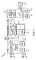
- FIG. 11is a functional block diagram of self-regulating or adjusting gastric band system of the invention utilizing a handheld controller communicating with remote controllers or services (such as web page-based controllers or services) via a telephone link;
- remote controllers or servicessuch as web page-based controllers or services
- FIG. 12is another functional block diagram showing the handheld controller and cradle of the system of FIG. 11 in additional detail;
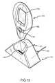
- FIGS. 13 and 14are perspective views of an exemplary implementation of a handheld controller and cradle according to the present invention, such as to implement the systems of FIGS. 10 and 11 ;
- FIG. 15is a flow chart of a normal mode of operating gastric band system, such as those described in FIGS. 10 and 11 , to regulate the size of an implantable gastric band;
- FIG. 16is a functional block diagram of a self-regulating gastric band system similar to that of FIG. 4 according to another embodiment of the invention showing the use of a software application or module to provide automated (or optional manually instigated) control of band pressure;
- FIG. 17is a block diagram similar to FIG. 16 showing a gastric band system according to another embodiment of the invention in which a pressure sensor is provided at or near an access port and a pressure analysis and adjusting module is used by an external control device for adjusting the fill of a gastric band;
- FIG. 18illustrates a graph of gastric band pressure data, which may be historical or provided via a display in real time
- FIG. 19illustrates an alternative self-regulating gastric band having a fluid reservoir that is separate from the band
- FIG. 20is a cross sectional view of the gastric band of FIG. 19 taken at line 20 - 20 illustrating the inner, expandable lumen used for fine tuning the inner diameter or size of the gastric band;
- FIG. 21illustrates a self-regulating gastric band system incorporating an expandable fluid reservoir incorporated in a fill tube extending to a fill port and schematically showing a control module in communication therewith;
- FIGS. 22A and 22Bare transverse sectional views through the fill tube of the system of FIG. 21 showing an exemplary expandable fluid reservoir in a first, W-shaped deflated state and a second, inflated state;
- FIGS. 22C and 22Dare transverse sectional views through the fill tube of the system of FIG. 21 showing an alternative expandable fluid reservoir in a first, U-shaped deflated state and a second, inflated state;
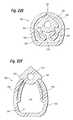
- FIGS. 22E and 22Fare transverse sectional views through the fill tube of the system of FIG. 21 showing an expandable fluid reservoir having an integral outer protective sheath in a first, deflated state and a second, inflated state;
- FIGS. 22G and 22Hare transverse sectional views through the fill tube of the system of FIG. 21 showing an asymmetric expandable fluid reservoir having an integral outer protective sheath in a first, deflated state and a second, inflated state;
- FIGS. 22I and 22Jare transverse sectional views through the fill tube of the system of FIG. 21 showing an alternative expandable fluid reservoir having a separate outer protective sheath in a first, deflated state and a second, inflated state, as well as an outer protective sheath.
- the inventionis directed to a self-regulating gastric band or band system that enables an operator (e.g., a physician or technician) to set operational parameters for a gastric band prior or after implantation in a patient.
- the self-regulating gastric bandthen is operable to directly monitor properties of or associated with the gastric band, to determine if these monitored or sensed properties are within the set operational parameters or bounds, and then, if not within the bounds, to automatically adjust the size of the gastric band (i.e., its inner diameter that establishes the size of a stoma in the patient's stomach) such that the monitored or sensed property or properties are within the present operation range or bounds.
- Self-regulating gastric band systems of the inventiongenerally can be used with numerous gastric band designs with many embodiments being particularly useful for those that include an inflatable portion or inner lumen that is expanded or contracted by increasing or decreasing the volume of fluid contained therein.
- the gastric band systems of the inventioninclude one or more sensors for directly sensing a band parameter, such as pressure of the fluid in the inflatable portion, and a controller that processes this sensed band parameter or property to determine whether to add or withdraw fluid from the band to finely tune its size (and the corresponding stoma size).
- a local fluid reservoirmay be provided that is connected to a pump assembly, which is controlled by the controller to pump fluid into or out of the band.
- the local fluid reservoiris provided within the gastric band itself, e.g., in an outer lumen or reservoir ring or member.
- An internal fill line or tubeis connected between the pump assembly and the inflatable portion or member of the gastric band to allow the volume to be controlled locally (e.g., instead of or in addition to a standard access port).
- Power for the pump assembly, controller, and sensoris typically also provided local to the gastric band, i.e., intracorporeally or adjacent the stoma and gastric band in the patient, rather than from an external power source such as an induction power source.
- Memoryis also associated with the controller to store band data and band operating ranges or bounds that are used to determine when to adjust the size of the gastric band, and these operating ranges or bounds (i.e., range limits) may be set before implantation or later set or modified via communications with an external controller/monitor.
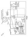
- FIG. 1illustrates a self-regulating gastric band system or apparatus 100 as it may appear when installed in a patient being treated for morbid obesity.
- the system 100is being used to form a stoma or smaller opening in the upper portion of the stomach near the esophagus to restrict food intake and flow. It is often useful or even necessary to vary the size of the stoma to properly treat a patient.
- the self-regulating gastric band system 100is adapted for self-regulation of its size based on sensed band parameters and operating parameters (such as a range of operating parameters with set upper and lower limits).
- the gastric band system 100includes a gastric band 110 that is inflatable by external or extracorporeal actions via a fill tube or line 112 that is connected to an access port 114 through which fluid can be pumped into the inflatable portion or member of the gastric band 110 .
- a fillingis typically performed as part of an initial sizing of the stoma as part of the implanting process performed by the physician or other technician.
- the band 110 and other components of the system 100are implanted in the same or similar surgical procedure as used with existing expandable or inflatable gastric bands. For example, a surgeon would typically dissect the tissues around the stomach to create a tunnel for the band 110 .
- the band 110is then introduced into the patient's abdomen, e.g., through a 18 mm or other sized trocar or the like or directly through the trocar hole in the skin.
- the band 110is then tunneled in place and positioned around the stomach.
- the other components of the system 100 including the internal band adjustment system or unit 130are placed near the stomach (such as just below the skin on top of the sternum or on the rectus muscle sheath proximate the access port) with fluid connection provided via fill/drain line 120 to the gastric band 110 and particularly to the inflatable or expandable member or portion of the band 110 (additional connections are provided in embodiments in which the band 110 also includes a local fluid reservoir for use in sizing the band 110 ). In other embodiments, the connection 120 is provided to the fill line 112 such that another connection to the band 110 is not required.
- the self-regulating gastric band system 100includes an internal band adjustment assembly or unit 130 that functions to sense a band parameter, such as fluid pressure in the inflatable or expandable portion or lumen or in the fill line 112 or a property such as surface tension/strain on the band or the like, to determine if this sensed or monitored band property or parameter is within a predefined acceptable band operating range, and if not, to adjust the size of the gastric band 110 .
- a band parametersuch as fluid pressure in the inflatable or expandable portion or lumen or in the fill line 112 or a property such as surface tension/strain on the band or the like
- the size adjustmentis achieved via the fill/drain line 120 by adding or removing liquid, such as saline, to or from the band 110 , which is explained in detail with reference to FIGS. 4-10 .
- the system 100further includes an external monitoring or control device 150 that includes a display element 154 that is used to display data received via wireless communications 152 with the internal band adjustment system or unit 130 , to display data such as new operational parameters to be sent to the internal system 100 , or to display historic or other data associated with the gastric band 110 .
- the external monitoring device 150also includes a keypad or other input area 156 for allowing an operator to enter data or input (such as to request data from the internal system 130 , to input a new setting for the gastric band 110 by adjusting its operating range, or the like).
- the gastric band 110may take many forms to practice the invention.
- the gastric band 110may be configured similar to the gastric bands described in U.S. Pat. Nos. 5,226,429 and 5,601,604, which are incorporated herein in their entirety by reference.
- the gastric band 110may include one of the gastric bands available from Allergan, Inc. (e.g., one of the bands in the LAP-BANDTM family of expandable gastric bands such as the 9.75, 10.0, 11.0 cm, the VG, or AP LAP-BANDs).
- gastric bands from various band manufacturers/distributorsthat could be used for this application include, but are not limited to: the Obtech (Ethicon) band, the AMI band, the Heliogast band, the Minimizer (Pier) band, and Cousin Bioband.
- FIGS. 2 and 3illustrate an embodiment of a self-regulating gastric band assembly 200 that includes one exemplary gastric band 210 that may used to implement the invention (such as for use as band 110 in system 100 ).
- the gastric band assembly 200includes the gastric band 210 and an internal adjustment system 230 , as described with regard to FIG. 1 and in more detail with FIGS. 4-10 , that generally includes a sensor(s) for directly sensing properties of band 210 , a controller with memory, an internal power supply, and a pump assembly (not shown in FIGS. 2 and 3 but described with reference to FIGS. 4-10 ).
- the gastric band 210includes a fill tube or line 212 that is used to provide a fluid connection between an access port (not shown) and an expandable or inflatable portion or lumen 226 in the band 210 .
- a belt 214 with a recessed surface 215 and raised portion 218are provided along with a buckle member 216 to allow initial forming of a circular loop or band of a particular initial size or inner diameter when the band 210 is implanted about a patient's stomach (e.g., to initially set the size to the band at 9 to 11 cm or another useful inner diameter) to provide an initial size of a stoma.
- the gastric bandincludes an inflatable portion or member that abuts the outer surfaces of the stomach.
- the gastric band 210includes a shell or molded shell 220 , an inner ring 222 , and an inflatable portion, member, or balloon 224 made of an elastic or other material that can be increased in size and later reduced in size.
- the inflatable member 224includes an internal lumen 226 for received volumes of fluid, e.g., saline or the like.
- the gastric band 210may be configured to provide a local fluid reservoir for storing fluid for expanding or deflating the inflatable portion 224 .
- the inner ring 222which is typically made of a more rigid material than the inflatable member 224 and is attached at 321 (such as with adhesive) to the shell 220 , includes a lumen or reservoir 323 for storing fluid that later can be pumped into the lumen 226 of inflatable portion 224 by the internal adjustment system 230 .
- the lumen or reservoir 323is useful as a store of fluid because reservoir connection tube or line 238 is provided to the internal band adjustment system 230 (such as to a pump (not shown) in the system 230 ).
- Fluid removed from the reservoir 323 formed by inner ring 222is pumped via line 340 by the internal band adjustment system 230 to the lumen 226 of the inflatable member 224 to increase the size of the gastric band (i.e., increase the outer diameter of a cross section of the band 210 as shown in FIG. 3 ) or to reduce the size of the ID formed by the band about the stomach to reduce the size of the stoma formed in a patient.
- the internal adjustment system 230is operated (based on sensed band parameters) to pump fluid from the lumen 226 as shown by arrow 350 via fill/drain line 234 which connects the lumen 226 of the inflatable portion 224 to the internal band adjustment system 230 (or to a pump in the system 230 ).
- Such removal of fluid from lumen 226decreases the size of the band 210 and inflatable member 224 while increasing the ID formed by the band 210 about the stomach and increasing the size of the patient's stoma.
- the fluid removed from the inflatable portion 224is pumped into the reservoir 323 as shown by arrow 340 for storage and later use in sizing or adjusting the gastric band 210 .
- FIG. 4illustrates in functional block form an exemplary self-regulating gastric band assembly or system 400 .
- the system 400includes an external monitoring and/or control device 410 that communicates wirelessly 426 with an internal band adjustment system 430 .
- the internal band adjustment system 430is implanted along with an expandable or adjustable gastric band 460 in an abdominal cavity of a patient to form a stoma in the patient's stomach to treat obesity, i.e., the gastric band is inflated or deflated by the addition or withdrawal of fluid to change the size of the gastric band and the inner diameter of the band, IDBAND, formed by the band in its circular configuration.
- the external monitoring and control device 410may take the form of a handheld, laptop, or desktop computer and/or communication device that includes a display element 412 for displaying information and an input/output component 414 for allowing a user to input data or information such as a keypad, touchscreen, and/or voice data entry feature and for wireless communications as shown at 426 with an I/O component of the internal band adjustment system 430 .
- the device 410further includes memory 416 for storing band data 418 , such as may be read from system 430 and provided by controller 432 and I/O 434 of internal system 430 and for storing band settings 420 , such as operating ranges or bounds (i.e., an upper and lower limit such as for a pressure range) for the gastric band 460 that may be entered with the control device 410 or present in the internal system 430 and later read by the external device 410 for storage in memory 416 and/or for modification or alteration by operation of the external control device 410 .
- the memory 416may also be used by the external control device 410 for storing sensor data 422 (and, in some cases, patient data) obtained by the sensor 450 of the internal band adjustment system 430 .
- the internal band adjustment system 430is shown to include a controller 432 , which may include a CPU and code useful for controlling operation of the system 430 .
- the systemfurther includes an I/O element 434 for communicating with the external monitoring and control device 410 .
- Memory 436is provided in the system 430 for storing band settings 438 , i.e., an acceptable operating range for a particular property or parameter of the gastric band 460 that is sensed by the sensor 450 such as an upper or lower pressure limit (e.g., 4 and 5 PSI) when the sensor 450 is a pressure sensor for the fluid in the inflatable portion of the gastric band 460 .
- band settings 438i.e., an acceptable operating range for a particular property or parameter of the gastric band 460 that is sensed by the sensor 450 such as an upper or lower pressure limit (e.g., 4 and 5 PSI) when the sensor 450 is a pressure sensor for the fluid in the inflatable portion of the gastric band 460 .
- the band settings 438may be set for the particular patient or as default settings prior to implanting the system 430 in a patient and/or the band settings 438 may be set or modified after implanting via the external monitoring/control device 410 so as to alter the size of the gastric band 460 and the resulting inner diameter, IDBAND.
- the memory 436may also be used by the controller 432 for storing other sensor and band data 440 such as data collected from the sensor 450 to provide a historical perspective of operation of the gastric band 460 and band information such as band serial number, manufacturer, and the like.
- the system 430includes the sensor 450 which preferably monitors directly properties or physical parameters of the gastric band 460 .
- the sensor 450may be provided in or linked to as shown at 452 a pressure transducer or other device in a fluid link or connection 448 between the gastric band 460 and the pump assembly 442 of the system 430 .
- a pressure transducer or other pressure sensing devicemay be provided as sensor 450 or in communication with the sensor 450 to measure pressure in the gastric band 460 such as by positioning in the inflatable portion of the band 460 , at an inlet port to the band 460 , in the fill line 478 which is in communication with access port 474 and external fill device 470 (which, in turn, is provided for initial filling of inflatable or expandable portion of the band 460 or for optional later adjusting of the band 460 ).
- the sensor 450may also be positioned so as to otherwise directly sense properties of the band 460 such as shown with line 456 , e.g., with a strain sensor indicating surface tension of the band 460 such as on a surface of the inflatable or expandable portion or with other sensing devices useful with measuring the present size of the gastric band 460 .
- the sensor 450may include the memory 436 for storing the band settings 438 such that when it senses a parameter of the band 460 that is outside a preset range (such as above a maximum setting or below a minimum setting) the sensor 450 may “wake up” the controller 432 to operate the pump assembly 442 .
- the sensor 450may be configured to be intelligent enough to determine when the gastric band 460 is outside a preset operational range and respond by alerting or alarming to cause the controller 432 to operate to control the pump 442 including transmitting the sensed band parameter to allow the controller 432 to act appropriately to adjust the band 460 .
- the senor 450may be periodically (or, in some cases, more frequently as to approach nearly continuous) operated to take an additional reading of the band property or parameter (as shown as 452 and 456 ) and to provide the sensed value to the controller 432 which, in turn, acts to compare the sensed band value with the band settings 438 to determine if adjustments of the band 460 are required or desired.
- a power supply 444such as a battery or the like is used to power the controller 432 and other power consuming components of the system 430 (such as the pump assembly 442 and the sensor 450 ).
- the system 430further includes pump assembly 442 and an internal reservoir 446 .
- the pump assembly 442may take a variety of forms (such as those shown in FIGS. 5-10 ) to hydraulically adjust the size of the band 460 in response to sensor 450 information and the invention is not limited to one particular pump or fluid transfer device.
- the internal or local reservoir 446is in fluid communication with the pump assembly 442 and provides fluid (such as saline) for pumping via fill/drain line 448 into the band 460 to increase its size and reduce the IDBAND and also provides a location for storing fluid that is pumped or allowed to flow based on pressure differentials from the band 460 via the line 448 and pump assembly 442 .
- the reservoir 446may be provided as a separate component in a housing (not shown) that is used to enclose or encapsulate the internal band adjustment system 430 or the reservoir 446 may be provided as a separate device, such as in the form of a balloon-like structure, that is provided proximate the system 430 housing and the band 460 . Further, in some embodiments, the reservoir 446 may be provided as part of the gastric band 460 itself such as in an outer lumen or member of the band shell (as is shown in FIGS. 2-3 and FIGS. 5-110 ).
- the pump assemblyis typically modular and can be used with any of number of gastric bands, e.g., those currently available from Allergan, Inc. such as the 9.75 cm, 10.0 cm, VGs, or APs LAP-BANDs.
- the pump in the pump assemblyreplaces the function of the manually adjustable access port.
- the materials used to construct the bandwill generally remain the same as normally employed, and the dimensions of the band, except the tubing in the case of a local reservoir being provided in the shell or tubing, will remain the same.
- alternate materialsmay be used to implement the invention such as materials selected specifically to improve performance, to increase acid resistance, or to achieve some other desired result.
- band tubingmay have 2 lumens to separate the saline for the reservoir and saline that is part of the band (as is shown in FIGS. 2 and 3 ).
- a long extended balloonmay be placed along the tubing to act as a reservoir.
- the pump assemblywill generally include one or more pumps (or pump-like devices for moving fluid in and out of the band), electronics, communication components, computer or intelligence components, and a power supply such as a battery or batteries.
- the internal gastric band adjustment assemblywill be sealed inside an outer housing made of a biocompatible material such as acetyl copolymer, PEEK, titanium, or the like.
- the power supplyis an implantable grade battery that is hermetically sealed in titanium prior to being placed into the pump assembly.
- the pump assemblymay have an over-ride port that allows for manual adjustments if needed such as with external fill device 470 via access port 474 shown in FIG. 4 .
- the self-regulating gastric band systemfunctions automatically or as a “set-it-and-forget-it” device.
- the systemmay function continually or periodically (such as hourly, daily, weekly, monthly, or some other selected monitoring period) sense a band parameter or property and then adjust such as via inflating and deflating the gastric band hydraulically with saline or another fluid.
- a band parameter or propertysuch as an inflating and deflating the gastric band hydraulically with saline or another fluid.
- the same or similar specification for saline fill volume and a fill burst of the bandwill apply to the self-regulating gastric band system.
- the adjustments in these self-regulating embodimentsare performed by the remote actuation of a micropump or pumps coupled with the sensor and with control electronics.
- the sensordetects directly a parameter or property of the band such as an internal parameter of the band, e.g., an internal band pressure, or an internal or external parameter such as stress and/or strain of the shell.
- the sensormay also include a linear motion sensor that detects changes in length in the band or in the inflatable portion of the band, with the sensor or controller acting to convert this detected length delta to stoma or band diameter measurements.
- the sensormay also be a distance sensor functioning to detect the distance between two points to detect a change in position. The sensor could be queried by an external monitoring or control unit via telemetry to gather data on the parameter being monitored for real time feedback to the clinician.
- the senoris programmed to “wake up” at intervals (or monitoring periods) to monitor parameters and to adjust the band to the ideal band parameter(s) established through testing or established to better treat a patient over a longer treatment period. If the parameters are not within the ideal range, the sensor will send a command to re-adjust as necessary to ensure that the band reads within the ideal parameter control limits or alternatively, the sensor will merely pass the gathered information from the band to the controller for use in determining whether the band is in a desired operating range.
- the sensormay “wake up” and determine that the band is monitoring an internal band pressure of “X psi” and determine based on a comparison with preset band parameters that the band needs to be adjusted such that its internal fluid pressure is at “Y psi” which may be a pressure at the midpoint within an operating range or any pressure within that range.
- the sensorin this arrangement, will communicate to the controller to cause the controller to activate the implanted pump and command the volume of fluid to be pumped into band or out of the band until the sensor reads within ideal parameter limits, e.g., by operating the pump until the sensor detects an internal fluid pressure in the band within the range or matching the midpoint of the present operating range (or other reset point saved in memory associated with the sensor or with the controller).
- the micropump(s)draw power from the implanted battery or power supply to allow for the adjustment, and, if included, the controller also activates one or more check valves to open (see FIGS. 5-10 ). To inflate the band further or to finely increase its size, the pump pulls fluid from the local reservoir into the band. To deflate the band or to finely decrease its size, the pump will pull fluid from the band back into the reservoir. Once the sensor reads within the specified parameter range, the valves will close to prevent fluid migration. The pump and sensor will then be shut off to conserve power until the sensor “wakes up” again.
- fluidwill be used to either inflate or deflate the shell to control the stoma size but in this case the change in size is handled internally using local control and a local fluid reservoir.
- the sensorAfter the parameter monitored by the sensor has been changed, the sensor will send a command or message to the controller to record the date the parameter was changed, the value of the new setting or sensed band parameter or property, and, in some cases, the delta or amount of the change.
- a clinician or operator of the systemcan use a handheld or other sized external monitor and control device external to the patient's body to query the sensor for a reading or to query the controller for a most recently stored value (or both). Aside from the external monitor device and access port, the system is self-contained to monitor and adjust itself.
- the pump assemblymay store a variety of data in addition to the band data and acceptable band operating range such as a serial number that can be remotely read by the external monitoring and control device to identify the implanted device including the implanted gastric band and internal gastric band adjustment system.
- the external deviceoften will take the form of a handheld control unit that may feature an LCD display and control panel to operate the device.
- the handheldmay feature a series of menus that allow an operator to program (or read/determine) the implant to contain in memory important information such as the band size, patient's name, implanting physician, and the date it is implanted.
- the handheldmay communicate with the sensor via telemetry through radiowaves.
- the FDA and globally recognized communications band(WMTS 402-405 Mhz) may be used in some embodiment, and an authentication process can be used to ensure that the device cannot be accidentally accessed or controlled by another control mechanism other than the handheld.
- the telemetry control signalcan be sent from approximately a foot or possibly a greater distance from the patient and will typically not require the patient to disrobe to query the sensor or to change its parameters.
- the handheld external monitoring deviceis preferably able to read and write information to the implant such as current pressure or parametric data, adjusting physician's name, the date with the handheld device often operating to store or retain the adjustment history in its own memory (this history can be stored in the internal adjustment system, too or only).
- the handheld devicemay also be password controlled to prevent unauthorized personnel from querying the device.
- the display of the handheldwhich may include visual and audio outputs, typically will display or output the sensed parameter of the band's condition or physical parameter whether this parameter or property is pressure, stress, strain, and/or linear measurement.
- the sensor querytypically will only take a few seconds, but the control of the micropump(s) may take longer, such as approximately 30 seconds per 1 psi of pressure change.
- the resolution of pressure readings and parameter rangeswill be fine and preferably will have greater resolution than is currently possible by manual syringe adjustments.
- data storageat least a portion of the information will be stored directly on the implanted internal system.
- the handheldmay be used to query the device and display on the screen data, such as the serial number, patient name, doctor's name, band size, fill volume, fill volume, and adjustment history.
- the implantcould be powered by a variety of internal power sources that meet the energy requirements such as the following: (a) kinetic energy creation by body motion stored onto a capacitor; (b) an implanted fuel cell; (c) an implanted power source powered by chemistry of the body; (d) an implanted power source powered by temperature change; and (e) implanted batteries that can be recharged by direct contact.
- the handheld control devicewill typically be powered by rechargeable batteries while some embodiments may use other power sources.
- a power cordmay be supplied to allow recharging of the device in between uses with in most embodiments a fully charged device performing a day's worth of queries of a plurality of implanted band systems.
- the self-regulating gastric band adjustment system of the present inventionpresents a number of design advantages.
- the systemprovides precise and safe operation and supports telemetric communication with the implant.
- the systemis configured so as to reduce risk of infections and to improve patient comfort.
- the implantable battery or power sourceprovides a reliable and consistent power supply.
- the systemcan be operated to provide feedback on the state of the implant, which can be used for improving therapeutic intervention and patient follow-up.
- the external monitoring and control devicesuch as device 410 of FIG. 4
- the sensor 450(or the controller 432 ) is queried by the external device 410 via telemetry 426 to gather data on the parameter being monitored by the sensor at 452 and/or 456 . Based on the current readings, the clinician or operator of the device 410 that is gathering this information can then change the monitoring limits (i.e., the band settings 438 that may be programmed into the sensor 450 when the sensor 450 is configured to intelligently monitor the operating bounds of the band 460 ) of the parameter such as to increase or decrease pressure or stress and strain of the gastric band.
- the monitoring limitsi.e., the band settings 438 that may be programmed into the sensor 450 when the sensor 450 is configured to intelligently monitor the operating bounds of the band 460
- the sensor 450(or controller 432 by storing new band settings 438 ) can then reprogrammed to read data and determine if the new data is within the modified control limits.
- the sensor 450sends a signal to the control mechanism 432 to adjust the band 460 such that (or until) the sensor 450 reads data (i.e., a gastric band property or parameter) within the control limits (or band settings 420 or 438 ).
- a bandmay be monitoring or reading a band parameter (such as fluid pressure within the band 460 ) between 2 and 3 psi when the clinician queries the sensor 450 by operating the external device 410 .
- the clinician, physician, or other operatormay then choose to increase the monitoring range of the band to a range having 5 psi as its midpoint.
- the physicianwill re-program the sensor 450 to monitor between 4.5 to 5.5 psi (such as by resetting the band settings 420 and/or 438 ) and send this to the sensor 450 telemetrically 426 .
- the sensor 450resets its monitoring limits (or the controller 432 resets its band settings 438 for use in comparison of sensor-obtained band parameters) and communicates with the controller 432 to activate the implanted pump assembly 442 such that a volume of fluid is pumped into the band or out of the band until the sensor 450 reads (via 452 , 456 ) within the control limits.
- the pumpdraws power from the implanted battery or power supply 444 to allow for the adjustment and also activates any check valves to open (as discussed with reference to FIGS. 5-10 ).
- the pump assembly 442pulls fluid from the reservoir 446 into the band 460 .
- the pump assembly 442pulls fluid from the band 460 back into the reservoir 446 .
- appropriate check valvesare closed to prevent fluid migration from or to the band 460 .
- the clinician or operatoruses the handheld 410 to query the sensor 450 for another reading. If confirmed, the pump assembly 442 and sensor 450 are shut off until queried again to conserve power.
- FIGS. 5-10illustrate particular self-regulating gastric band systems that may be employed to practice the invention.
- Each described system providing an alternative example of an effective pump assemblymay be employed in a gastric band system (such as for the pump assemblies of internal band adjustment systems of FIGS. 1-4 ).
- the described systemseach employ a pressure sensor for use in detecting or determining the fluid pressure in the inflatable or expandable portion of the gastric band (hereafter labeled “inner expandable ring”).
- the inventionis not limited to only a pressure sensor and that many embodiments of the invention (including those described in FIGS. 5-10 with a substitution of the sensor) employ other sensors for directly sensing one or more gastric band properties or physical parameters.
- the sensors employedmay included:
- a schematic of a self-regulating gastric band system 500includes a gastric band 510 for implanting in a patient in a circular configuration about their stomach to form a stoma.
- the band 510includes an outer ring reservoir 512 for storing fluid for use in adjusting the size of the band 510 , e.g., a lumen may be provided in outer ring or shell of the band that extends at least partially about the circumference of the band 510 (or along the band's length when it is not implanted or placed in its circular configuration such as from a head to a tail of the band or from a first end to a second end of the band).
- An inner expandable or inflatable ring 514is provided in the band 510 that is formed of a material that allows it to expand as it received a fluid and to deflate or contract when the fluid is removed or drained.
- expandable gastric bandsare well known in the art, and nearly any of these known bands may be employed in the system 500 with modifications to include the outer ring reservoir 512 and a fluid connection line 517 (or reservoir fill/drain line or tube) provided to the reservoir 512 .
- the inner expandable ring 514is filled and drained of fluid via a fill line or tube 516 (which more accurately may be considered a band size adjustment line).
- Initial sizing of the band 510is performed via access or manual port 518 that is typically implanted just beneath the patient's skin and which is connected to the fill line 516 .
- Sizingincludes a clinician injecting a volume of fluid that is typically selected for the gastric band 510 in an attempt to obtain a desired inner diameter of the band 510 .
- Fine tuning and ongoing “self-regulation”is performed in the system 500 using an internal band adjustment system made up of a pump assembly 530 , a sensor 522 , a power supply 528 (e.g., one or more batteries), and control and communications components.
- the system 500may interact with an external monitor/control device as discussed in detail above.
- an antenna or other wireless communication component 524is provided in the internal assembly and linked to the control 526 , and this antenna 524 allows telemetry to be used to communicate band parameters and other information (again, as discussed in detail above) with the external monitoring/control device.
- a housing 520is provided such that the components of internal band adjustment system can be isolated within the patient.
- a pump assembly 530is provided along with the sensor 522 , the antenna 524 , a control 526 , a battery or power source 528 , and memory 529 (which may be incorporated in the sensor 522 and/or control 526 ).
- the sensor 522 , control 526 , battery 528 , and memory 529provide the functionalities described in detail with reference to FIG. 4 and the preceding description.
- the sensor 522is a pressure sensor for sensing the fluid pressure in the inner expandable ring 514 .
- the fill line 516is routed to the housing 520 from the access or manual port 518 through or via contact with the sensor 522 to the inlet of the inner expandable ring 514 .
- the sensor 522includes a pressure transducer that can sense directly the back pressure applied by fluid in the inner expandable ring 514 on fluid in the fill line 516 .
- the sensor 522 or a portion of the sensor 522is provided in the band 510 such as in or near the inlet port to the inner expandable ring 514 for the fill line 516 or interior to the inner expandable ring 514 .
- the sensor 522may be inactive for periods and be activated by the control 526 , by an internal timing mechanism, and/or by an external monitoring device.
- the sensor 522when activated takes pressure readings and provides these to the control 526 for storage in memory 529 and/or for comparison against a preset operating range (i.e., minimum and maximum pressure limits or bounds such as 3 to 7 psi or more likely 4 to 5 psi, which may be considered band settings) stored in memory 529 .
- a preset operating rangei.e., minimum and maximum pressure limits or bounds such as 3 to 7 psi or more likely 4 to 5 psi, which may be considered band settings
- the sensor 522may have intelligence and memory and act to compare the read pressure readings (i.e., directly obtained band property) to band settings programmed into the sensor 522 .
- the sensor 522may awaken the controller 526 to operate to raise or lower the pressure in the band 510 by operating the pump assembly 530 to add or withdraw fluid from the inner expandable ring 514 .
- the battery 528provides a local power source for power consuming components within the housing 520 such as the control 526 , the sensor 522 , and any pumps and/or electronic valves in the pump assembly 530 .
- the memory 529may store pressure readings from the sensor 522 and other data related to the gastric band 510 (such as the band identification information, the date of implantation, and the like) as well as, in some cases, data related to the patient (such as patient name, last treatment date/time, and the like).
- the pump assembly 530functions generally to respond to control signals from the control 526 to either pump fluid into the inner expandable ring 514 or to remove or withdraw fluid from the inner expandable ring 514 to thereby size the band 510 , whereby a band parameter or property monitored by the sensor 522 is returned to within an operating range or to within band settings.
- the pump assembly 530 of system 500includes a bleed valve 532 (e.g., a ceramic bleed valve or the like operated by a spring plunger) in fluid communication with the outer ring reservoir 512 via line 517 .
- the bleed valve 532is operated by a pump 534 (e.g., a 7 psi Bartel actuator pump or other pump having the same capacity or a larger or smaller capacity or pressure rating) that is primed with an internal reservoir 536 .
- the bleed valve 532is also shown to be connected to the fill/drain line 516 of the inner expandable ring 514 .
- the bleed valve 532is provided to allow the pump assembly 530 to equalize the pressure between the outer ring reservoir 512 and the inner expandable ring 514 , which may be desirable in some embodiments (and when not, these components associated with the bleed valve 532 may be omitted from pump assembly 530 ).
- the bleed valve 532may be used to drain/withdraw fluid from the inner expandable ring 514 .
- the sensor 522may sense a pressure that is too high, i.e., above an upper limit of a band setting or operation range, and the control 526 may respond to a signal from the sensor 522 to activate the pump 534 to open the bleed valve 532 .
- a pressure differential between the outer ring reservoir 512 and inner expandable ring 514results in flow of fluid from the inner ring 514 via fill line 516 and bleed valve 532 to the outer ring reservoir 512 (e.g., this operational embodiment assumes the fluid reservoir 514 is maintained at a lower pressure than fluid in the inner expandable ring 512 ).
- the sensor 522continues to monitor the pressure in the inner expandable ring 512 and when it (or the control 526 ) determines that the pressure is within the desired operating range (or more typically at or near the center or midpoint of such a range) the control 526 is operated to deactivate the pump 534 to shut the bleed valve 532 .
- the pump assembly 530 of system 500also includes a pair of check valves 542 , 546 (e.g., Bartel micro check valves or the like) between which is positioned a pump 540 (e.g., a 20-psi Bartel custom actuator pump or the like).
- a pump 540e.g., a 20-psi Bartel custom actuator pump or the like.
- One check valve 542is connected to the outer ring reservoir 512 via line 517
- one check valve 546is connected to the inner expandable ring 514 via fill line 516 .
- the pump 540is connected between the check valves 542 , 546 with flow during pumping to be from the outer ring reservoir 512 to the inner expandable ring 514 .
- the pump 540can be used to increase the size of the band 510 when operated by the control 526 to pump fluid from the outer ring reservoir 512 through the check valves 542 , 546 into the inner expandable ring 514 .
- the control 526provides a shut off signal when the pressure of the fluid in the inner expandable ring 514 is within the set operating range (or at or near a midpoint or other preset point within such a range) as determined by operation of the sensor 522 and control 526 .
- the band 510may be adjusted to have a smaller size by withdrawing fluid from the inner expandable ring 514 via the pump 540 .
- the sensor 522may sense a pressure that is too low (i.e., less than a lower bound or limit of the operating range or band parameters) and provide this information to the control 526 .
- the control 526then signals the check valves 542 , 546 to open and fluid is allowed to flow backwards through the pump 540 to the outer ring reservoir 512 via line 517 .
- This embodimentalso assumes that the pressure of the outer ring reservoir 512 is less than that of the fluid in the inner expandable ring 514 , and that the pump 540 is configured to allow back flow when it is not actively pumping.
- the control 526When the sensor 522 senses a pressure within the programmed operating range (or a midpoint or other set point within that range) as determined by the sensor 522 and/or the control 526 , the control 526 operates to close check valves 542 , 546 .
- FIG. 6illustrates one physical arrangement for the pump assembly 530 .
- the housing 520is a one-piece unit or box that encloses the sensor 522 , the control 526 , the battery 528 , the pumps 534 , 540 , and internal reservoir 536 (as well as other components of the pump assembly 530 ).
- the housingalso provides fluid ports or connection points for the fill line 516 and reservoir connection line 517 .
- the materials used for the housing 520are preferably biocompatible, and the housing 520 is preferably constructed to be leak resistant (e.g., water or fluid “tight”) to support extended use of the pump assembly as an implant.
- the housing 520may take different shapes such as a cylinder, a square, or other useful shape and may be modular such that differing components are provided in two or more enclosures that may be attached or provided as detached modules.
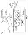
- FIG. 7illustrates a schematic of another embodiment of a self-regulating gastric band system 700 .
- the system 700is configured similarly to that of system 500 with an adjustable gastric band 510 having an inner expandable ring 514 and an outer ring reservoir 516 that with fill/drain lines 516 and 518 , respectively.
- An access port 518is connected to the fill/drain line 516 to allow external filling of the inner expandable ring 514 with saline or other fluid, such as during the implant process to initially size the band 510 .
- a sensor 722is provided in fill/drain line 516 to sense the fluid pressure of the gastric band 510 in the inner expandable ring 514 .
- An antenna 724 , a control 726 , a battery 728 , and memory 729are provided with functionality similar to that of like components in system 500 .
- the system 700differs from the system 500 in the configuration of the pump assembly 730 provided as part of the internal band adjustment system in housing 720 .
- the pump assembly 730includes a bleed valve 732 connected to the fill/drain lines 516 , 517 that is operated similarly to valve 532 by operation of the pump 734 and reservoir 736 and control 726 .
- the pump assembly 730differs from pump assembly 530 with replacement of a single pump 540 with a plurality of pumps 740 , 742 , 744 (e.g., three 7-psi Bartel actuator pumps or other pump useful for this function/purpose) that are arranged in series between check valves 746 , 748 .
- the pumps 740 , 742 , 744are operated via battery 728 and control 726 to pump fluid from the outer ring reservoir 512 into inner expandable ring 514 when the sensor 722 detects a pressure lower than a preset lower pressure limit. Further, in some embodiments, the check valves 746 , 748 are opened by control 726 and powered by battery 728 to allow fluid in inner expandable ring that is under a pressure above a present upper pressure limit (as detected by sensor 722 ) to flow out of the inner expandable ring 514 through the pumps 740 , 742 , 744 into the outer ring reservoir 512 until determined by sensor 722 and control 726 to be within the preset operating range.
- FIG. 8illustrates an embodiment of a self-regulating gastric band system 800 is similar to systems 500 and 700 including an expandable gastric band 510 with a self-contained fluid reservoir 512 and within housing 820 a pressure sensor 822 , a communication module 824 , a controller 826 , a local power supply 828 , and memory 829 .
- the system 800however includes a pump assembly 830 in the housing 820 that differs from the pump assemblies 530 , 730 .
- an optional bleed valve 832is provided between the outer ring reservoir and the inner expandable ring 514 that is operable to maintain a desired pressure differential between the fluid in these two portions of the band 510 (or system 800 ).
- bleed valve 832may be omitted.
- the pump assembly 830includes a pair of check valves 846 , 848 connected to the fill/drain lines 516 , 517 .
- Pumping or fluid motive forcesare provided by a syringe or other chamber 842 that is in fluid communication with the two check valves 516 , 517 and therefore, with the two reservoirs or portions 512 , 514 of the band 510 .
- Fluidis drawn into and forced out of the chamber 842 by operation of a squiggle motor 838 that is sealed in a motor casing 834 having a bellows 836 to support movement of a shaft/plunger 840 connected to the motor 838 (e.g., a Squiggle motor or the like) and chamber 842 .
- a squiggle motor 838that is sealed in a motor casing 834 having a bellows 836 to support movement of a shaft/plunger 840 connected to the motor 838 (e.g., a Squiggle motor or the like) and chamber 842 .
- the sensor 822senses pressure in the inner expandable ring 514 of the band 510 .
- the sensed or monitored band propertyis either used by the sensor 822 to determine if the band pressure is within a programmed or preset operating range or such a determination is made by control 826 .
- the control 826operates the motor 838 to pump fluid from the outer ring reservoir 512 into the inner expandable ring 514 via check valves 846 , 848 and fill/drain lines 516 , 517 until the pressure in the band 510 as sensed by sensor 822 is within the preset operating range (or typically some amount higher than the lower limit).
- the control 826may adjust the pressure (and corresponding size of the ring 514 ) by opening check valves 846 and 848 to allow fluid at a higher pressure in the inner expandable ring 514 to flow to the outer ring reservoir 512 via fill/drain lines 516 , 517 until the pressure detected by the sensor 822 is again within the range (or at a pressure a preset amount below the upper pressure limit).
- FIG. 9illustrates another self-regulating gastric band system 900 similar to the systems 500 , 700 , and 800 in that it includes a gastric band 510 and a housing 920 that encloses a pressure sensor 922 in the fill line 516 of the band 510 , an antenna or communication element 924 , a control device 926 , a battery 928 , and memory 929 .
- the pump assembly 930is similar to assembly 830 in that it includes a bleed valve 932 in fluid communication with the inner expandable ring 514 and outer ring reservoir 512 via lines 516 , 517 for maintaining a desired pressure differential between the two lumens or reservoirs 512 , 514 .
- the pump assembly 930differs from assembly 830 in with the insertion between check valves 942 , 946 of a pumping mechanism that is made up of a motor casing 934 sealing a squiggle motor 940 that is used to drive or move a diaphragm 938 via a shaft extending through or into bellows 936 .
- Other operations of the system 900are similar to that of system 800 .
- FIG. 10illustrates a self-regulating gastric band assembly 1000 that is configured similar to system 500 of FIG. 5 .
- Differences between the systemsinclude the positioning of the sensor 1022 external to the housing 1020 between the inner expandable ring 514 and a check valve 1049 in the fill line 516 .
- the sensor 1022is in communication (wired or wireless) with the controller 1026 , which acts to communicate with an external monitoring/control device (not shown in FIG. 10 ) via antenna or communication element 1024 , to store data received from sensor 1022 and external monitoring/control device in memory 1029 , and to power the pump assembly 1030 (as needed) with battery 1028 , which also powers the controller 1026 .
- the controller 1026is also configured to operate (as discussed in detail above) the pump assembly 1030 to automatically maintain the band 510 within a desired operating range typically defined by a lower and an upper limit (e.g., a lower pressure limit and an upper pressure limit) by pumping fluid into and out of the inner expandable ring 514 based on band properties sensed by sensor 1022 (e.g., pressure of fluid in line 516 and in ring 514 ).
- a lower and an upper limite.g., a lower pressure limit and an upper pressure limit
- the system 1000also differs from system 500 in the configuration of its pump assembly 1030 .
- the pump assembly 1030includes a bleed valve 1032 for bleeding higher pressure fluid in the inner expandable ring 514 (when sensed by the sensor and based on control signals from the control 1026 ) to the outer ring reservoir 512 .
- the assembly 1030however includes a different pump 1034 , e.g., a 5-psi Thinxxs pump or the like, than that used in the system 530 , which is primed by internal reservoir 1036 to operate the bleed valve 1032 in response to signals from the control 1026 .
- the system 1000further differs from system 500 in that a plurality of pumps 1040 , 1042 , 1044 , 1046 (e.g., 5-psi Thinxxs pumps or other useful pumps) are positioned between check valves 1048 , 1049 and the reservoir 512 and inner expandable ring 514 rather than a single pump 540 .
- These serially-arranged pumps 1040 , 1042 , 1044 , 1046are operated to pump fluid from the reservoir 512 into the inner expandable ring 514 when the sensor 1022 detects a pressure below (or outside low) a minimum pressure defining a lower bound of the desired operating range or the programmed pressure range for the band 510 .
- FIG. 5-10there are many different pump assembly configurations that may be used to implement the present invention. Additionally, other components may be varied to achieve the desired functionality of a self-regulating gastric band.
- the systems shown in FIGS. 5-10included a fluid reservoir provided in a lumen or integral portion of the gastric band. In some embodiments, it may be desirable to have the fluid reservoir be provided within the pump housing. In other cases, the fluid reservoir may be provided as a component external to the pump housing and external to the gastric band, such as by providing a separate elastic sack, balloon, or other similar structure that would be useful for storing fluid for pumping into the band and out of the band by the pump assembly.
- an implanted bandby a physician or other technician via a telephone link.
- Thisis achieved by providing a controller local to the patient and a remote controller local to the physician or technician, with the two controllers communicating via a wired and/or wireless telephone link.
- the local controllercan be thought of as a remotely adjustable band (RAB) handheld controller (or the controller can be fixed but local to the patient) or RHC.
- RABremotely adjustable band
- the primary function of the RHCis to: locate the implanted pump, control the implanted pump, provide an easy to use programming and system status display, allow access to the RHC functions through remote dialup, provide a web server application which allows for web page-based control of all functions when accessed through remote dial up, and provide a standard wireless link to a cradle, which provides charging power to the controller and a telephony link (for accessing the web page and/or other controller).
- the local controller or RHCmay, for example, be used to communicate via the antennae of the systems shown in FIGS. 1-10 , and the use of such an RHC is explained in more detail in the following description.
- FIG. 11illustrates in functional block form a gastric band system 1100 that uses a RAB controller 1150 to control adjustments of an implanted (or implantable) band 1190 .
- FIG. 12illustrates RAB controller 1150 and its cradle 1110 in more detail.
- the system 1100includes a cradle 1100 for providing telephony connections and power for a RAB handheld controller or RHC 1150 .
- the RHC 1150in turn is used to control via transferred data over wireless link 1162 an implanted pump 1170 , which adjusts or regulates the size of a gastric band 1190 by controlling fluid transfer over connection 1179 .
- Fluidis supplied in this example by external reservoir 1180 (e.g., external to a housing of the pump assembly 1170 or via a manual port 1184 (e.g., for an initial filling or sizing of the ban 1190 ) via connections 1181 , 1185 .
- the pump assembly 1170includes telemetry circuitry 1172 , controller and memory 1174 and one or more hydraulic pumps 1178 .
- the RHC 1150is shown to include a user interface 1152 and display 1154 along with a keypad (or user input mechanism) 1164 to allow a user (such as gastric band patient or other operator of the system 1100 ) to view data from the pump assembly 1170 and data received remotely via the telephone link 1118 and to allow the user to make adjustments and enter data in some cases.
- the RHC 1150further includes a system controller 1156 , a wireless circuitry and antenna or cradle link 1158 for communicating with the cradle 1110 , an implant telemetry 1160 for communicating with the telemetry circuitry 1172 of the implanted pump assembly 1170 , and a power supply/battery 1168 to allow the RHC 1150 to be used outside the cradle 1110 .
- the cradle 1110provides a power link 1128 by providing a power link 115 to a power supply 1104 via power supply 1120 and RHC charger 1126 . More significantly, the cradle 1110 includes a controller 1111 and a telephone/data link 1118 to facilitate remote control of the RHC 1150 and pump assembly 1170 via a telephone jack or other connection 110 that is linked 1103 with a line interface 1112 to communicate with the RHC 1150 via wireless communication circuit/antenna 1114 .
- the primary functions of the RHC cradle 1110are to: charge the RHC battery 1168 , store the RHC 1150 when not in use, provide telephone/line interface including a modem (in some cases as shown in FIG. 12 ) for data access via interface 1112 , implement a standard wireless data link 1118 between the modem and RHC 1150 to allow remote access to the RHC features and pump assembly 1170 , and allow access to the RHC functions through remote dialup.
- FIGS. 13 and 14illustrate one useful physical implementation of the RHC 1150 and the cradle 1110 . These figures show that the RHC 1150 can easily be removed and inserted or docked into the cradle for charging via power connection (or docking connector) 1128 .
- a telephone line 1103is connected to (or connectable to) cradle 1110 as is a power line 1105 (such as a 12 volt direct current line).
- the display 1154 upon which a user interface 1152 would be providedis shown in the RHC 1150 as is a keypad 1164 and a power on/off switch or button 1356 .
- the RHC 1150may be configured in a number of ways to include the implant telemetry access antenna and standard wireless antenna 1156 , 1160 with these shown in FIG.
- the RHC 1150is configured for easy handheld operation to allow a user to place the RHC 1150 near the patient and the gastric band 1190 to facilitate communications with implant telemetry circuitry 1172 in the pump assembly 1170 and ease of data input/output via display 1154 .
- the useful features of the system 1110 and the RHC 1150include: (a) the implantable pump 1170 that the RHC 1150 controls is self-powered and does not require power to be transferred by the controller 1150 ; (b) the implantable pump 1170 performs adjustments to the band 1190 until a desired band pressure is achieved (as opposed to a desired volume); (c) the RHC 1150 contains a standard wireless interface 1158 , such as Bluetooth or ZIGBEE, connecting the RHC 1150 to the telephony interface 1114 in the RAB cradle 1110 which in turn connects via interface 1112 and connection 1103 to a remote computer or controller (not shown) capable of performing a dial-up access or otherwise communicating data and control information to the RHC 1150 ; (d) the RHC 1150 contains networking software run by controller 11
- the RHC 1150operates in the following high level modes: normal, remote accessed, docked, and powered down.
- FIG. 15illustrates operation of the RHC 1150 (or gastric band system 1100 ) in the normal mode for remotely adjusting or regulating 1500 a gastric band in a patient.
- the RHC's primary functionis to access and control the RAB implantable pump 1170 .
- Wireless access to the implantable pump 1170may be, for example, through the Medical Implant Communications Service (MICS) band operating in the 402-405 MHz frequency range.
- the communication protocol between the RHC 1150 and implantable pump 1170may be kept compliant with patient privacy regulations and health industry regulations.
- the flow chart of FIG. 15shows a typical set of activities leading to an adjustment. Adjustments are typically in the form of pressure changes in the band as opposed to discrete volumetric change.
- the RHC 1550is powered on at 1510 , such as by pressing a button or moving a switch 1356 on the RHC 1550 .
- a password entrymay be required to use the RHC 1550 to prevent unauthorized users from adjusting the band 1190 .
- the RHC 1550is operated by the system controller 1156 to search and find the implanted pump 1170 such as communications being performed between the implant telemetry 1160 in the RHC 1150 and the telemetry circuitry 1172 of the pump assembly 1170 with the link 1162 being established at 1540 when the assembly 1170 is found by the RHC 1150 .
- the RHC 1550acts to retrieve and display data that is stored in the memory 1174 of the implanted pump assembly 11170 .
- the RHC 1550prompts via UI 1152 and display 1154 for a pressure change input (i.e., does the user wish to change or adjust the pressure in the gastric band 1190 to adjust the band 1190 ).
- a pressure change inputi.e., does the user wish to change or adjust the pressure in the gastric band 1190 to adjust the band 1190 .
- inputhas been received (such as via input by the user via keypad 1164 and/or UI 1152 ) and a pressure change command(s) is sent via link 1162 from the RHC 1150 to the implanted pump assembly 1170 .
- the RHC 1550waits for a confirmation from the implanted pump assembly 1170 that it has completed the pressure change in the gastric band 1190 (e.g., via operation of the pump 1178 by the controller 1174 to add or remove fluid via connections 1179 , 1181 and fluid reservoir 1180 as discussed in detail with reference to FIGS. 1-10 ).
- the process 1500may then continue with retrieval of additional data at 1550 or more typically, with displaying a confirmation and then prompting for input of additional changes at 1560 .
- An innovative feature of the system 1100is the capability for a physician to perform remote band adjustment.
- physicians or other operatorsare able to connect securely from their office computers to the RHC 1150 .
- This connection and control communicationsare achieved by operating the physician's or other operator's computer to “dial-up” and connect to the RAB system 1100 through a telephone modem or link in the cradle 1110 .
- the following sequence of eventsoccur in one embodiment to achieve remote access to and control of the RAB system: (a) the patient connects the cradle 1110 to an active telephone jack 1102 using a standard telephone cord 1103 , with the physician typically being made aware of the phone number of the cradle/jack prior to attempting the remote access; (b) the physician uses standard windows dial-up networking software to dial the RAB system 1100 ; (c) the cradle 1110 contains the telephone interface and modem circuitry 1112 , and upon detection of a telephone ring signal on the telephone line 1103 , the cradle 1110 automatically “picks up” and the modem 1112 is activated; (d) the modem 1112 in the cradle 1110 establishes a connection 1103 with the physician's computer modem (not shown); (e) the cradle 1110 then establishes a wireless data link 1118 between the modem or interface 1114 and the RAB Handheld Controller 1150 , which contains networking software (e.g.,
- the wireless data linkwill be either Bluetooth, ZIGBEE, or other communication protocol/technique compliant.
- the docked mode of operationis primarily used for charging the RHC 1150 . However, remote access may be provided for the purpose of preprogramming an adjustment or retrieving patient data.
- the RHC functionsare suspended except for battery charging and charge monitoring.
- An implantable pump assemblyis provided that allows for a non-invasive pressure management of an implantable gastric band, and this function is typically invoked as a response to commands transmitted from the RAB Handheld Controller (RHC) shown in FIGS. 11-15 or other controller.
- RHCRAB Handheld Controller
- the implanted pump assembly and its componentsare internally powered (i.e., powered locally by a battery or the like rather than remotely or external to the patient's body).
- the implanted componentsinclude the following functional components: an enclosure; an external reservoir; a manual port; a fluid pump (e.g., a Bartels 20 PSI pump with active valve or the like); a control circuitry (e.g., for controlling the pump and any valves); telemetry circuitry and antenna; and a battery and power supply circuitry.
- the RAB implantable pumpcan be implemented as a piezoelectric 20 PSI (or other capacity) pump, e.g., a pump with an active valve incorporated into its design.
- the implantable pumpis preferably self-powered through a custom implantable battery designed for long term implantation.
- the pumphas inlet and outlet valves.
- check valves at the pump inlet and the pump outletare used to eliminate or control leakage, such as micro check valves.
- the systemmay use a piezoelectric or active valve or the like.
- the systemdirectly pumps fluid from the reservoir to the band, changing the band pressure. Band pressure release is accomplished through a separate sub-system. Increase in pressure in the band is done directly via the pump. Decrease in pressure is achieved through pressure release followed by re-pumping the band to the proper pressure.
- a 20-psi pump with 30-psi minimum back pressure withstanding check valvemaintains directional flow between an external reservoir and the gastric band.
- the pumpe.g., a 20-psi piezoelectric pump or the like, is for pressure increase in the band and is monitored by a pressure sensor. Because of the nature of the piezo material, the flow is not reversible for pressure relief in the band. Pressure is maintained in the band once the pump is shut down. No leakage or back-flow occurs because of check valves that are integrated into the pump or provided separately.
- an active valve/flow re-direction mechanisme.g., a piezo-active valve
- the active valveis opened to equalize pressure between the band and the reservoir. Once equalization is achieved, the active valve is shut down.
- the main pumpis then activated to increase the pressure to the desired pressure in the gastric band.
- the pressure of the band or the fluid in the bandmay be automatically monitored and controlled/adjusted by an internal band adjustment system.
- This automatic adjustingmay be combined with periodic reporting of pressure readings and settings to an external control device and, in some cases, with changes of pressure settings being provided by the external control device.
- FIG. 16another embodiment of a self-regulating gastric band assembly or system 1600 is shown in FIG. 16 .
- the system 1600is shown to be a modification of system 400 of FIG. 4 , with like numbered components not being explained in detail here. Of course, these modifications could be made to any of the self-regulating systems/devices described herein (such as those shown in FIGS. 5-12 ).
- the system 1600is particularly adapted for self-adjusting a gastric band 460 based on a sensed pressure of the fluid in the band 460 (e.g., in the expandable portion of the band).
- the senor 450 of the internal band adjustment system 430is provided in fluid communication with the band fluid such as by connection to or placement in the band 460 , in line 448 or at/in pump assembly 442 , in line 478 , or in access port 474 .
- the sensor 450is used to sense or take readings of the pressure of fluid in the band 460 and controller 432 acts to store the pressure readings 1620 in the memory 436 (e.g., as part of the stored sensor data 440 ).
- one or more pressure targets 1630may also be stored as part of the band settings 438 , and the controller 432 functions to adjust the volume of the fluid in the band 460 via reservoir 448 and pump assembly 442 to maintain this target pressure 1630 (or to maintain fluid or band pressure within a range encompassing the target pressure 1630 to allow for some variance as discussed above).
- the pressure readings 1620are communicated to an external monitoring/control device 410 wirelessly 426 via I/O devices 434 , 414 .
- the datais stored as historical pressure data 1650 in the memory 416 of the external device 410 .
- the patient pressure setting 1640is stored in the memory 416 and is provided to or written to the memory 436 of the internal band adjustment system 430 for use in controlling the pressure in band 460 .
- the sensed information 1650may be reported to a user of the external device 410 by generating a pressure graph or report 1666 on display 412 (e.g., see the report or graphics 1800 of FIG. 18 as an example).
- the internal band adjustment system 430includes a pressure analysis and adjusting module 1610 .
- Thismay be a software application (or combination of software and hardware) that is run by the controller 432 to process the pressure readings 1620 to determine if the pressure target 1630 is being maintained during ongoing operations.
- the module 1610can also be used to initially establish the pressure target or ideal pressure setting 1630 for a particular patient based on analysis of pressure readings 1620 . Then, once set, the module 1610 may be used to adjust the pressure of the band 460 in an ongoing manner and/or in response to commands or queries from the external device 410 .
- the controller 432may also operate to reduce pressure in the band 460 when there is an obstruction or other problem/event for a patient for which loosening of the band 460 temporarily is desirable.
- the pressure graph 1810 of FIG. 18illustrates a graph of pressure over time for a gastric band, such as band 460 , installed in a patient.
- Pressure data 1620was collected from the sensor 450 over a period of time and over a number of band fill or use operations that included initial or nominal fill, a later adjustment or increase of fluid volume in the band, and a further adjustment to increase the fluid volume to an overfill point.
- the graph 1810is useful for showing how pressure data 1620 can be analyzed by the pressure analysis and adjustment module 1610 to establish a pressure target 1630 and to identify when further adjustments may be desirable (e.g., when the pressure target 1630 should be adjusted up or down to suit changing operating parameters such as changes with regard to the patient and/or the band or associated equipment).
- the graph 1810is representative of a real-time pressure curve generated from pressure readings 1620 from an actual patient in which a band 460 has been implanted.
- the band 460may be filled with a nominal amount of fluid to achieve a first or second pressure (e.g., about 5 to 7 PSI) as shown at 1820 .
- This first portion of the curve 1810i.e., from 0 to 517 seconds, corresponds to when the band 460 was at a fill volume that was inducing satiety in a patient or was slightly overfilled beyond that point.
- this fill pointwas determined initially by filling the band, such as with external fill device 470 , and receiving feedback from the patient to identify the nominal fill to achieve such feelings of satiety.
- the band 460was filled with additional fluid so as to increase the pressure, e.g., to an average or median pressure of about 8 PSI in this example.
- additional fluidso as to increase the pressure, e.g., to an average or median pressure of about 8 PSI in this example.
- PVARor standard deviation
- the pressure analysis and adjustment module 1610can be configured to determine a pressure target either with no input from an external device 410 or with an initial target being provided by the device 410 .
- the pressure analysis and adjustment module 1610functions to analyze sensed pressure of fluid in the band 460 (e.g., band pressure) and to establish a target pressure setting 1630 for the band 460 (or for the patient using the band 460 ).
- the internal band adjustment system 430may operate to awaken or activate the sensor 450 to take pressure readings from of the fluid pressure in the band 460 (e.g., multiple readings per second or more or less readings).
- the external fill device 470may be used to provide a conventional, nominal fill of the band 460 . For example, it may be known that a volume of fluid can be added via access port 474 (such as with a needle) to not overfill the band but also that likely will not place the band 460 at an ideal or target operating pressure 1630 for any patient.
- the module 1610may cause the controller 432 to collect pressure readings 1620 for a period of time (or to collect a set number of readings) with the sensor 450 . These pressure readings may coincide with the initial step of the first portion 1820 of the pressure curve 1810 , which in this example is about 5 PSI.
- the module 1610operates to analyze the pressure variation (e.g., between a maximum and minimum) at this fill volume. This determined maximum (or average or median) pressure variation, PVAR, or a standard deviation may be stored in memory 436 and compared to a preset maximum acceptable pressure variation.
- the module 1610causes the controller 432 to operate the pump assembly 442 to pump fluid from reservoir 448 into the band 460 to increase the pressure to a next incremental setting that is higher than the nominal setting by a particular amount (e.g., by 0.5 PSI, 1 PSI, 2 PSI, or some other useful increment), such as from 5 PSI to about 7 PSI as shown in the example in FIG. 18 .
- the module 1610may cause the controller 432 to add a preset volume to the band 460 to increment up or increase the pressure of the band 460 rather than adjusting to a preset pressure increase.
- the sensor 450is used to gather another set of pressure readings 1620 .
- the module 1610processes these readings to determine a pressure variation (or standard deviation for the readings) and compares this variation or deviation to a preset maximum. Again, if the maximum is not exceeded (i.e., the variation in pressure is relatively small), the module 1610 determines that the band 460 may not yet have reached its ideal pressure setting.
- This ideal or target pressure settingis, in this case, defined as one in which pressure readings are maximized but the pressure variations as measured by differences between maximum and minimum values (or as a standard deviation) do not exceed a threshold level while a fill volume is held steady or constant.
- a pressure value below such a “maximum” pressure but above a pressure associated with the nominal or initial fill volume for the band 460is utilized in operations.
- the target pressure 1630may be similar across a population of patients, but it typically will vary enough due to manufacturing tolerances and differences among patients to make it desirable for the module 1610 to be operable to identify a setting 1630 for a particular patient after the band 460 is implanted.
- the module 1610stores the determined pressure variations in memory 436 , such as in sensor data, and causes the controller 432 to again operate the pump assembly 442 to increase the pressure in the band 460 by pumping more fluid from the reservoir 448 to the band 460 .
- the band adjustmentmay be continued until a pressure increment is reached or to add a preset increase in band fluid volume.
- the pressures sensor 450continues to gather pressure readings 1620 that are stored in memory 436 .
- the adjustmentis completed (e.g., such as after an increase in pressure of 0.5, 1, 1.5, 2, or similar increase or from about 7 PSI to 8 PSI as shown in FIG.
- the controller 432halts operation of the pump assembly 442 and continues to collect readings 1620 from the sensor 450 (such as for a preset period of time or until a preset number of readings are obtained as defined by module 1610 ).
- the module 1610determines a pressure variation at this new band fill level and compares this determined variation to the preset acceptable variation for the band 460 . If the determined variation does not exceed the maximum, another incremental change in fill for the band is initiated by the module 1610 . Such as to the pressure level shown at curve portion 1840 of FIG. 18 .
- the module 1610may determine that at this new fill level that the band pressure has a pressure variation, PVAR, that is too large because it matches or exceeds the preset maximum value for the band 460 .
- the module 1610may act to cause the controller 432 to operate the pump or valve assembly 442 to reduce the amount of fluid in the band 460 by returning or pumping fluid back into the reservoir 448 .
- the module 1610may instruct the controller 432 so as to return to the prior fill level (or prior band pressure) or to a fill level or volume (or associated band pressure) between the prior fill level and the present level such as to a midpoint between the two levels.
- Additional readingsmay be taken at this level and if the maximum acceptable pressure variation is not exceeded, the pressure associated with this fill level may be stored as the ideal or target pressure 1620 for the patient (or the fill level may be increased incrementally and the process repeated one or more times prior to setting the target pressure 1620 at a level where the maximum pressure variation setting is not exceeded). If the pressure variation is exceeded, the fill may be further reduced until the pressure readings show the variation setting is not exceeded.
- the module 1610then can be used to monitor the pressure readings 1620 in a continuous or more periodic fashion and to operate the controller 432 as discussed above to maintain the pressure of the band 460 at the target setting 1630 or in a range that includes the setting 1630 (such as at the midpoint of the range).
- the pressure readings 1620 during this process of identifying the target pressure 1630 and otherwiseare stored in memory 436 .
- the module 1610may store the pressure variations (or standard deviations) determined at each band fill level as well as, in some embodiments, the volume of fluid added in each step.
- This datais then transferred via wireless communications 426 to the external monitoring/control device 410 for storage in memory 416 , where it can readily be accessed for viewing and review such as by a doctor or other use of device 410 .
- the transferred pressure readings 1650can be used by the control device 1610 in generating graphs 1810 as shown in FIG. 18 .
- the graph 1810can be displayed on the device at 1666 as the data is being gathered by the internal band adjustment system 430 to provide real time feedback/information.
- the information in memory 416may also be transferred to a personal computer or other computing device for storage and/or further analysis.
- the system 1600allows for real time pressure monitoring of the band 460 .
- the device 410a handheld or desktop device
- the device 410typically includes software (not shown) to allow an operator to see actual pressure output from the sensor 450 in a pressure graph or display 1666 (e.g., a graph similar to curve 1810 of FIG. 18 ).
- the pressure display 1666may include a pressure curve (e.g., curve 1810 or the like) and/or additional information such as average pressure, pressure standard deviation or variation, pressure minimum, and pressure maximum as measured over time.
- the curves in display 1666are useful for allowing an operator such as physician to visualize the pressure changes within the band 460 while treating a patient or adjusting a band 460 .
- a physiciancan not only listen to the patient verbal feedback but also match with measured pressures and pressure changes/variations after an adjustment to decide if additional adjustments may be useful or advisable.
- the curves or changes in pressureare generally generated by peristalsis in the esophagus that is translated down to the stomach and the attached band 460 . This can be thought of as a pressure column that is pushed down the stoma of the esophagus and through the stoma at the stomach/band interface.
- the software module 1610acts to analyze pressure readings from a sensor in fluid communication with the band fluid so as to identify when these pressure changes or variations are within an acceptable range (e.g., are below a present maximum variation or standard deviation).
- the preset maximum deviation that is used by the module 1610may be set for a band in a number of ways.
- the preset maximum pressure variation or standard deviationmay be set for all bands in a consistent manner or be set for a particular implanted band.
- the preset maximummay be determined by studying a group of patient to gather pressure data similar to that discussed relative to the curve 1810 of FIG. 18 and based on such a study an acceptable maximum variation may be set for a particular band design (such as 0.05 to 0.5 PSI and more typically less than about 0.15 PSI or less than 0.1 PSI). This preset may then be programmed into each system 430 for use by the module 1610 in determining the pressure target 1630 for the particular patient (e.g., provide a patient-specific target pressure for the band).
- the study of implant patientsmay be performed in a number of ways to determine the preset maximum pressure variation or deviation but typically will involve some level of patient participation or feedback.
- pressure data or readingswere collected from conventional gastric bands for a number of patients at several fill levels or volumes. Specifically, pressure readings were obtained after “optimum” fill levels were set (or prior to adjustment to increase fluid volumes in the band), after an adjustment (or injection of additional fluid), and when the patient was swallowing water after completion of the adjustment. Patients were asked to participate in a study when they were not currently in need of an adjustment, i.e., a physician had previously set a band at a target fill level or fluid volume and its associated pressure.
- Pressure datawas collected from the bands in these patients by inserting a needle into their access ports and connecting the needle fluid path to a pressure transducer or sensor.
- the transducer used in this particular experimentwas capable of obtaining multiple pressure readings per second and the equipment connected to the transducer could store these readings and also graph the results in substantially real time (and it is believed similar equipment may be useful for systems 430 of the invention for the sensors 450 ). It was observed that when a patient's band was at the “optimal” or target setting provided by the physician the pressure readings only varied minimally as is shown in portion 1820 of curve 1810 of FIG. 18 . For example, this minimal variation may be less than about 0.1 PSI. When the patient swallowed water gradual increases in pressure was noted but variations were still relatively small.
- a pressure analysis and adjustment modulesuch as module 1610
- a pressure analysis and adjustment modulecan be designed that follows a similar process to be followed with an individual patient to determine a pressure target for that patient with a particular gastric band (e.g., moving from a nominal fill volume to higher fill volumes and back again until a fill volume is identified for which the pressure variation remains below a preset maximum pressure variation setting).
- the module(such as module 1610 ) is more complex and is able also to establish the maximum acceptable pressure variation through analysis of various fill levels and the variations identified at each level.
- FIG. 17illustrates one such adjustment tool or system 1700 .
- This tool or system 1700can be used to determine an optimum level of adjustment or band fill based on the pressure response in the band 460 without requiring implantation of an internal adjustment system and its associated sensors.
- the controller (such as a hand held device) 410may be configured to allow a physician to gradually increase the pressure in the band 460 .
- the system 1700includes a control device 410 (such as a handheld, desktop, or other electronic device) with a controller or processor 1710 that controls operation of display 410 , I/O 414 , and memory 416 and runs pressure analysis and adjusting module 1720 , which may be a software application similar to module 1610 of FIG. 16 .
- the memoryis used for storing band data 418 as discussed above, band settings 420 that may include patient pressure settings 1750 including the ideal or target pressure setting that is determined by pressure analysis and adjusting module 1720 , and sensor data 422 that may include real time pressure data or pressure readings from a sensor 1710 and historical pressure data 1740 .
- the system 1700is also configured to allow pressure sensing of an implanted gastric band 460 , and in the illustrated embodiment, this is achieved with a pressure sensor 1710 (e.g., a pressure transducer or the like) that is mounted in or near the access port 474 so as to be in contact with fluid in fill line 478 (and, therefore, the fluid in band 460 ).
- the sensor 1710may also be provided in the external fill device 470 or a line between the port 474 and device 470 .
- the sensor 1710is provided in the gastric band 460 itself.
- the sensor 1710is preferably selected to communicate wirelessly or with a wired connection (e.g., a disconnectable connection) the sensed or read pressures to I/O 414 .
- the module 1720is preferably configured to allow an operator such as a physician to readily establish a desirable or target pressure setting for the band 460 .
- the module 1720may be configured to process pressure readings from the sensor 1710 at one or more fill volumes for the gastric band 460 , such as when the pressure is being gradually, incrementally increased with the external fill device 470 (e.g., a needle).
- the module 1720may function to generate graphs 1760 that are displayed by the controller 1710 on display 410 (such as the graph/curve 1810 of FIG. 18 ).
- This graph 1760may be correlated with the patient in which the band 460 is implanted to identify the satiated fill levels and overfill levels (e.g., portions 1820 and 1830 , 1840 , respectively, of curve 1810 ).
- the module 1720may take this data to determine pressure variations or standard deviations at each fill level.
- the module 1720may act to correlate the variations at each fill level and provide a recommended target fill pressure that will result in pressure variations generally staying below a particular variation level (e.g., such as below 0.5 PSI, below 0.2 PSI, below 0.1 PSI, or some other variation identified by an operator of the device 410 of system 1700 or by the module 1720 itself).
- the data in memory 416can be collected and downloaded to the physician's or operator's computer or computer system (e.g., a database in such system) to track pressures over time for the patient.
- the system 1700can be used for initially setting a pressure for the band 460 and also to later monitor pressure of the band 460 via sensor 1710 such as by queries to the sensor 1710 .
- the system 1600 in FIG. 16 and other figureswas generally described as self-adjusting, there are situations where it is desirable for these systems to be manually controlled. For example, it may be desirable for a physician or other operator to initiate pressure monitoring operations of the module 1610 so as to allow pressure readings 1620 , 1650 to be observed on a graph 1666 or for other reasons.
- the system 1600is adapted to be awakened by an operator of the external device 410 , such as a technician/physician or the patient themselves. This may be useful when there is an obstruction in the stoma above the position of the band 460 . Obstructions result in discomfort by the patient.
- the device 410may be operated to transmit a “wake up” signal over connection 426 to the internal band adjustment system 430 .
- the module 1610(or another software module) may process the wake up signal and trigger an auto-adjustment of the band 460 .
- the module 1610will determine that the pressure readings 1620 from the sensor 450 are too high or above the target setting 1630 (or out of a desired pressure range relative to such setting 1630 ).
- the module 1610responds to such high or out of range pressures by causing the controller 432 to operate the pump assembly 442 to decrease the volume of fluid in the band 460 (e.g., pumping fluid to the reservoir 448 or opening valves to allow flow). Such flow is performed until the obstruction passes and the pressure is out of range on the low side.
- the module 1610acts automatically to refill the band 460 with fluid from reservoir 448 (e.g., using power supply 444 to operate the pump 442 ).
- the system 1600may further include a “quick” release valve or other device to allow the pressure to be automatically or manually bled off from the band.
- the system 1600may include a fluid release mechanism, which may include one or more valves or the like, that is remotely activated by an external controller to release a portion of the fluid from the cavity.
- the fluid release mechanismmay be activated automatically such as by providing a safety valve (e.g., a one way check valve) in a line between the band or its lumen/cavity/shell that is selected to open at pressures over a particular maximum pressure that may be associated with the particular gastric band or with the patient and/or the treatment regimen.
- a safety valvee.g., a one way check valve
- the fluid release mechanismmay be part of the internal adjustment system or be provided by additional components and be activated by commands from the internal controller, processing module, and/or by commands from an external controller or monitoring device.
- the measured pressurecan be reduced in the event that the external controller, the internal controller, or the check valve or similar device has determined that the measured pressure of the fluid in the cavity is greater than a upper limit of the operating pressure range or is greater than a second maximum pressure set above the upper limit (e.g., 1 to 2 PSI above the upper limit or other useful maximum allowable pressure for a band).
- FIGS. 19-21illustrate an alternative embodiment of a self-regulating gastric band assembly 200 ′ that is in many respects similar to the system 200 described with reference to FIGS. 2 and 3 , and so like parts will retain the same element numbers.
- the assembly 200 ′includes an exemplary gastric band 210 that may used to implement the invention (such as for use as band 110 in system 100 ).
- the gastric band assembly 200 ′includes the gastric band 210 and an internal adjustment system (not shown) that generally includes a sensor for directly sensing properties of the band 210 .
- the gastric band 210includes a fill tube or line 212 ′ that provides a fluid connection between an access port 240 ( FIG. 21 ) and an expandable or inflatable portion or lumen 226 in the band 210 .
- a belt 214 with a recessed surface 215 and raised portion 218are provided along with a buckle member 216 to allow initial forming of a circular loop or band of a particular initial size or inner diameter when the band 210 is implanted about a patient's stomach (e.g., to initially set the size of the band at 9 to 11 cm or another useful inner diameter) to provide an initial size of a stoma.
- the gastric bandincludes an inflatable portion or member that abuts the outer surfaces of the stomach.
- the gastric band 210includes a shell or molded shell 220 , a solid inner ring 222 ′, and an inflatable portion, member, or balloon 224 made of an elastic or other material that can be increased in size and later reduced in size.
- the inflatable member 224includes an internal lumen 226 for received volumes of fluid, e.g., saline or the like.
- the gastric band 210may be configured to provide a local fluid reservoir for storing fluid for expanding or deflating the inflatable portion 224 , though in this embodiment the reservoir is not shown as a lumen within the band itself.
- the inner ring 222 ′may be a separately formed structural member attached to the shell 220 , or may be co-formed along with the shell 220 .
- an internal adjustment systemdesirably includes a controller with memory, an internal power supply, and a pump assembly (not shown in FIGS. 19 and 20 but described with reference to FIGS. 4-10 ).
- a control module 242 shown schematically in FIG. 21may function in the same manner as the previously described internal adjustment system 230 shown in FIG. 2 , though with different flow paths. Namely, because the alternative fill tube 212 ′ incorporates an exemplary fluid reservoir, described in detail below, the control module 242 preferably connects to the fill tube 212 ′ at the end closest to the gastric band 210 .
- control module 242may include control valves in dual flow paths between the reservoir and internal lumen 226 of the gastric band 210 for alternately inflating and deflating the lumen as necessary or desired.
- control module 242could attach to the access port 240 as shown by the possible dashed line connections.
- an implantable fluid reservoir for filling and deflating the inflatable lumen of the gastric bandmay be provided as a separate component in a housing associated with an internal band adjustment system (such as system 430 of FIG. 4 ) or the reservoir may be provided as a separate device, such as in the form of a balloon-like structure, that is provided proximate the internal band adjustment system or the band.
- the reservoirmay be provided as part of the gastric band itself such as with the lumen 323 shown in FIG. 3 .
- various expandable reservoirsare provided along the fill tube 212 ′. Each will be described below, after a brief description of the use of such reservoirs.
- an elongated fluid reservoirextends along a substantial length of the fill tube 212 ′, which is typically about 18 inches (46 cm) long.
- the fill tube 212 ′has a low profile during implant so that it along with the belt 214 can easily slide through the buckle member 216 until the buckle snaps into the recessed surface 215 . Consequently, reservoirs incorporated into the fill tube 212 ′ are delivered in a collapsed or deflated configuration, and are later inflated, preferably via the access port 240 , with saline or other such physiologic fluid. Once inflated, the reservoir remains available as a source of fluid and a drain container for increasing or decreasing the fluid level within the gastric band lumen.
- Fluid removed from the reservoiris pumped by the control module 242 via a fill/drain line (not shown) to the gastric band lumen 226 of the inflatable member 224 to reduce the size of the ID formed by the band about the stomach to reduce the size of the stoma formed in a patient.
- the control module 242operates to pump fluid from the lumen 226 via the fill/drain line back to the reservoir and increase the ID formed by the band 210 about the stomach, thus increasing the size of the patient's stoma.
- a first embodiment of a fill tube/reservoiris not shown but includes an elongated collapsible tube attached concentrically around or alongside the fill tube.
- the reservoir tubecould be evacuated of air prior to implant of the system to cause it to closely conform around or against the fill tube and present a low profile for ease of band buckling.
- an elongated collapsible fluid reservoirextends along a substantial length of the fill tube.
- a “substantial length”means that the reservoir and fill tube extend in parallel for at least a few inches, potentially the entire length of the fill tube.
- the reservoirmay be formed separately and connected to the fill tube during manufacture, or the two components may be formed simultaneously from the same material.
- the fluid reservoiris expandable and the fluid reservoir and fill tube are co-extruded such that the reservoir collapses around at least a portion of the fill tube in a first, deflated state and expands to be substantially adjacent the fill tube in a second, inflated state of the reservoir.
- a protective sheath surrounding the deflated reservoir tubecould protect against accidental puncture by graspers and the like, and be removed after band placement and prior to saline expansion of the reservoir.
- the collapsible portion as well as the protective sheathcould be made of silicone, polyurethane, PTFE or other flexible polymers.
- a second embodiment of a fill tube/reservoir 250is shown in a first, deflated state in FIG. 22A , and a second, inflated state in FIG. 22B .
- a central tube 252 having an inner lumen 254provides the fill tube functionality, and desirably remains open to permit later manual introduction of saline to the gastric band system if needed.
- An expandable reservoir 256assumes a collapsed configuration in the first state of FIG. 22A , and an inflated substantially tubular configuration in the second state of FIG. 22B . In the collapsed configuration the reservoir 256 has a convoluted shape and folds around the central tube 252 in two wings 258 a , 258 b that connect at a temporary webbing 260 .
- An inner reservoir lumen 262has a sideways C-shape in the first, deflated state of the reservoir 250 .
- the wings 258 a , 258 btend to expand away from one another in the direction of arrows 264 , ultimately rupturing the temporary webbing 260 .
- a perforated linemay be formed in the webbing 260 to facilitate this rupture.
- the convoluted first state of the reservoir 256easily fits though the buckle member 216 , whereupon the reservoir 256 may be filled with saline to assume the expanded second state.
- the fill tube/reservoir 250is formed as a co-extrusion with the wall thickness of the reservoir 256 less than that of the central tube 252 .
- FIG. 22CAnother embodiment of a fill tube/reservoir 270 is shown in a first, deflated state in FIG. 22C , and a second, inflated state in FIG. 22D .
- a fill tube 272 having an inner lumen 274connects to a reservoir 276 via a neck portion 278 .
- a reservoir lumen 280has a U-shape in the collapsed first state of FIG. 22C , with two wings 282 a , 282 b of the reservoir 276 extending on either side of the fill tube 272 .
- expansion forces 284cause the wings 282 a , 282 b to spread out, ultimately forming the expanded second state of FIG. 22D .
- FIGS. 22 E/ 22 F and 22 G/ 22 Hillustrate two alternative fill tube/reservoirs having a protective outer shell or sheath surrounding the inflatable reservoir at all times.
- the outer sheathprotects the reservoir from damage from graspers and the buckle member 216 , and also shields the reservoir from pressure influences from the body. These two designs are exemplary only and many others are contemplated.
- FIGS. 22E and 22Fillustrate a fill tube/reservoir 290 wherein a fill tube 292 and reservoir 294 are contained within a split outer sheath 296 in a first, collapsed state, whereas the fill tube 292 emerges from within the sheath in a second, expanded state.
- the fill tube 292connects to an inner surface of the sheath 296 via a pair of flexible walls 298 that form a part of the reservoir 294 .
- the fill tube 292has an arrowhead shape with outward shoulders 300 defining channels 302 for receiving free edges 304 of the outer sheath 296 .
- a reservoir lumen 306is defined partly by an inner surface of the sheath 296 and partly by the flexible walls 298 .
- the fill tube/reservoir 290 and split outer sheath 296are integrally formed as a co-extrusion with the wall thickness of the reservoir 294 less than that of the outer sheath 296 .
- a fill tube 312 and reservoir 314are again contained within a protective outer sheath 316 in a first, collapsed state, whereas the fill tube 312 emerges from within the sheath in a second, expanded state.
- the fill tube 312connects on one side via a web 318 and on another side via a flexible wall 320 to the outer sheath 316 .
- a reservoir lumen 322is defined partly by an inner surface of the sheath 316 and partly by the flexible wall 320 .
- the fill tube 312Upon inflation of the reservoir lumen 322 , expansion forces cause the fill tube 312 to expand outward (rotate clockwise in the figures) until a free edge 324 of the outer sheath 316 engages a channel 326 formed on one side of the fill tube 312 , as seen in FIG. 22H .
- the locking featureensures that the protective outer sheath 316 remains at all times around the reservoir 314 .
- the fill tube/reservoir 310 and outer sheath 316are integrally formed as a co-extrusion with the wall thickness of the reservoir 314 less than that of the outer sheath 316 .
- FIGS. 22I and 22Jare transverse sectional views through a still further alternative fill tube/reservoir 330 with an alternative expandable fluid reservoir having a separate outer protective sheath.
- a central fill tube 332 having an inner lumen 334is integrally connected to an expandable reservoir 336 via a bridge 338 .
- the reservoir 336assumes a collapsed configuration in the first state of FIG. 22I , and an inflated substantially tubular configuration in the second state of FIG. 22J .
- the reservoir 336has a U-shape like the reservoir 276 of FIGS. 22C and 22D , with two wings 342 a , 342 b extending on either side of the fill tube 332 .
- the fill tube/reservoir 330also has a protective sheath 344 as described above, though in this embodiment the sheath is formed separately from the reservoir and is connected thereto during manufacture. That is, the sheath 344 comprises a longitudinally split tube that is biased into the compact configuration of FIG. 22I folded around the fill tube/reservoir 330 with its ends overlapping.
- the sheath 344connects to the fill tube/reservoir 330 along a lower generatrix via a bead of adhesive or spot weld 346 , as will be known by those of skill in the art. Expansion of the reservoir 336 spreads open the sheath 344 , which remains protecting the reservoir at all times. This embodiment permits the sheath 344 to be made of a different material than the reservoir 336 , which may be an advantage during manufacture.
- the gastric bands that are adjusted by the internal band adjustment systems of the inventionmay be external to the stomach as shown in FIG. 1 , for example, or may be provided or implanted internal to the stomach and/or esophagus, i.e., the gastric bands regulated according to the invention may be intragastric bands.
- Such an intragastric bandmay take the same or similar form of the bands described with reference to FIGS.
Landscapes
- Health & Medical Sciences (AREA)
- Life Sciences & Earth Sciences (AREA)
- Engineering & Computer Science (AREA)
- Heart & Thoracic Surgery (AREA)
- Veterinary Medicine (AREA)
- Public Health (AREA)
- General Health & Medical Sciences (AREA)
- Animal Behavior & Ethology (AREA)
- Biomedical Technology (AREA)
- Surgery (AREA)
- Medical Informatics (AREA)
- Molecular Biology (AREA)
- Pathology (AREA)
- Biophysics (AREA)
- Physics & Mathematics (AREA)
- Vascular Medicine (AREA)
- Obesity (AREA)
- Child & Adolescent Psychology (AREA)
- Nursing (AREA)
- Orthopedic Medicine & Surgery (AREA)
- Computer Networks & Wireless Communication (AREA)
- Immunology (AREA)
- Hematology (AREA)
- Surgical Instruments (AREA)
- Prostheses (AREA)
Abstract
Description
- 1. Pressure Sensors, such as those available from CardioMems and Tronics Microsystem, SA;
- 2. Implantable grade stress-strain sensors, e.g., those available from CardioMems and Tronics Microsystem, SA or being developed by these companies individually or in joint efforts with Inamed (the assignee of this patent application);
- 3. Linear motion sensors, such as those available from Microstrain, Inc. (e.g., see http://www.microstrain.com/images/sensorman.jpg, which is incorporated herein by reference);
- 4. Distance sensors, such as those distributed by Microstrain, Inc., to measure the distance between two points;
- 5. Force sensors, such as those distributed by Microstrain, Inc., to measure the force exerted against an area by the saline;
- 6. Thermal sensors, such as those available or in development by Verichip or by Verichip and Inamed (the assignee of this patent application), to measure a thermal gradient from a low level heat source to approximate distance; and
- 7. Shell thickness gauge to detect reduction in shell wall thickness due to elongation during expansion.
Claims (17)
Priority Applications (10)
| Application Number | Priority Date | Filing Date | Title |
|---|---|---|---|
| US11/754,091US7798954B2 (en) | 2006-01-04 | 2007-05-25 | Hydraulic gastric band with collapsible reservoir |
| AU2008256879AAU2008256879A1 (en) | 2007-05-25 | 2008-05-22 | Hydraulic gastric band with collapsible reservoir |
| JP2010509544AJP5318859B2 (en) | 2007-05-25 | 2008-05-22 | Hydraulic gastric band with a container that can wither |
| PCT/US2008/064448WO2008147832A1 (en) | 2007-05-25 | 2008-05-22 | Hydraulic gastric band with collapsible reservoir |
| BRPI0812162-1A2ABRPI0812162A2 (en) | 2007-05-25 | 2008-05-22 | HYDRAULIC GASTRIC TRACK WITH COLLABABLE RESERVOIR |
| CA2687986ACA2687986C (en) | 2007-05-25 | 2008-05-22 | Hydraulic gastric band with collapsible reservoir |
| ES08769577.1TES2509016T3 (en) | 2007-05-25 | 2008-05-22 | Hydraulic gastric band with compressible tank |
| EP08769577.1AEP2162102B1 (en) | 2007-05-25 | 2008-05-22 | Hydraulic gastric band with collapsible reservoir |
| US12/850,038US8308630B2 (en) | 2006-01-04 | 2010-08-04 | Hydraulic gastric band with collapsible reservoir |
| US13/184,456US8323180B2 (en) | 2006-01-04 | 2011-07-15 | Hydraulic gastric band with collapsible reservoir |
Applications Claiming Priority (3)
| Application Number | Priority Date | Filing Date | Title |
|---|---|---|---|
| PCT/US2006/000013WO2007081304A2 (en) | 2006-01-04 | 2006-01-04 | Self-regulating gastric band |
| US11/472,902US8043206B2 (en) | 2006-01-04 | 2006-06-22 | Self-regulating gastric band with pressure data processing |
| US11/754,091US7798954B2 (en) | 2006-01-04 | 2007-05-25 | Hydraulic gastric band with collapsible reservoir |
Related Parent Applications (1)
| Application Number | Title | Priority Date | Filing Date |
|---|---|---|---|
| US11/472,902Continuation-In-PartUS8043206B2 (en) | 2006-01-04 | 2006-06-22 | Self-regulating gastric band with pressure data processing |
Related Child Applications (1)
| Application Number | Title | Priority Date | Filing Date |
|---|---|---|---|
| US12/850,038ContinuationUS8308630B2 (en) | 2006-01-04 | 2010-08-04 | Hydraulic gastric band with collapsible reservoir |
Publications (2)
| Publication Number | Publication Date |
|---|---|
| US20070265645A1 US20070265645A1 (en) | 2007-11-15 |
| US7798954B2true US7798954B2 (en) | 2010-09-21 |
Family
ID=39545109
Family Applications (3)
| Application Number | Title | Priority Date | Filing Date |
|---|---|---|---|
| US11/754,091Expired - Fee RelatedUS7798954B2 (en) | 2006-01-04 | 2007-05-25 | Hydraulic gastric band with collapsible reservoir |
| US12/850,038Expired - Fee RelatedUS8308630B2 (en) | 2006-01-04 | 2010-08-04 | Hydraulic gastric band with collapsible reservoir |
| US13/184,456ActiveUS8323180B2 (en) | 2006-01-04 | 2011-07-15 | Hydraulic gastric band with collapsible reservoir |
Family Applications After (2)
| Application Number | Title | Priority Date | Filing Date |
|---|---|---|---|
| US12/850,038Expired - Fee RelatedUS8308630B2 (en) | 2006-01-04 | 2010-08-04 | Hydraulic gastric band with collapsible reservoir |
| US13/184,456ActiveUS8323180B2 (en) | 2006-01-04 | 2011-07-15 | Hydraulic gastric band with collapsible reservoir |
Country Status (8)
| Country | Link |
|---|---|
| US (3) | US7798954B2 (en) |
| EP (1) | EP2162102B1 (en) |
| JP (1) | JP5318859B2 (en) |
| AU (1) | AU2008256879A1 (en) |
| BR (1) | BRPI0812162A2 (en) |
| CA (1) | CA2687986C (en) |
| ES (1) | ES2509016T3 (en) |
| WO (1) | WO2008147832A1 (en) |
Cited By (43)
| Publication number | Priority date | Publication date | Assignee | Title |
|---|---|---|---|---|
| US20090124535A1 (en)* | 2007-11-13 | 2009-05-14 | Peter Markland | Viscous terpolymers as drug delivery platform |
| US20090198261A1 (en)* | 2008-01-30 | 2009-08-06 | Medical Components, Inc. | Gastric Inflation Band with Integrated Infusion Catheter |
| US20100158978A1 (en)* | 2008-12-23 | 2010-06-24 | Peter Markland | Bioactive spray coating compositions and methods of making and uses thereof |
| US20100160891A1 (en)* | 2008-12-23 | 2010-06-24 | Tipton Arthur J | Elastic implantable composites and implants comprising same |
| US20100168807A1 (en)* | 2008-12-23 | 2010-07-01 | Burton Kevin W | Bioactive terpolymer compositions and methods of making and using same |
| US20100191271A1 (en)* | 2009-01-29 | 2010-07-29 | Lilip Lau | Assembly and method for automatically controlling pressure for a gastric band |
| US20100191265A1 (en)* | 2009-01-29 | 2010-07-29 | Cavu Medical, Inc. | Assembly and method for automatically controlling pressure for a gastric band |
| US20110040313A1 (en)* | 2009-08-14 | 2011-02-17 | Dlugos Jr Daniel F | Implantable restriction device with protective member |
| US20110172687A1 (en)* | 2010-01-11 | 2011-07-14 | Woodruff Scott A | Telemetry Device with Software User Input Features |
| US8034065B2 (en)* | 2008-02-26 | 2011-10-11 | Ethicon Endo-Surgery, Inc. | Controlling pressure in adjustable restriction devices |
| US20120184980A1 (en)* | 2011-01-18 | 2012-07-19 | Gt Urological, Llc | Vessel occlusive device and method of occluding a vessel |
| US20130281771A1 (en)* | 2011-02-17 | 2013-10-24 | Allergan, Inc. | Hydraulic gastric band with reversible self-opening mechanism |
| US20140364685A1 (en)* | 2013-06-06 | 2014-12-11 | Coloplast A/S | Artificial urinary sphincter system |
| US8920921B2 (en) | 2010-08-30 | 2014-12-30 | Surmodics Pharmaceuticals, Inc. | Terpolymer blends and their use as pressure-sensitive adhesives |
| US8951546B2 (en) | 2008-12-23 | 2015-02-10 | Surmodics Pharmaceuticals, Inc. | Flexible implantable composites and implants comprising same |
| US8979885B2 (en) | 2012-02-24 | 2015-03-17 | Elwha Llc | Devices, systems, and methods to control stomach volume |
| US9011365B2 (en) | 2013-03-12 | 2015-04-21 | Medibotics Llc | Adjustable gastrointestinal bifurcation (AGB) for reduced absorption of unhealthy food |
| US9067070B2 (en) | 2013-03-12 | 2015-06-30 | Medibotics Llc | Dysgeusia-inducing neurostimulation for modifying consumption of a selected nutrient type |
| US9415197B2 (en) | 2008-12-23 | 2016-08-16 | Surmodics, Inc. | Implantable suction cup composites and implants comprising same |
| US9456916B2 (en) | 2013-03-12 | 2016-10-04 | Medibotics Llc | Device for selectively reducing absorption of unhealthy food |
| US9526648B2 (en) | 2010-06-13 | 2016-12-27 | Synerz Medical, Inc. | Intragastric device for treating obesity |
| US10349982B2 (en) | 2011-11-01 | 2019-07-16 | Nuvasive Specialized Orthopedics, Inc. | Adjustable magnetic devices and methods of using same |
| US10413436B2 (en) | 2010-06-13 | 2019-09-17 | W. L. Gore & Associates, Inc. | Intragastric device for treating obesity |
| US10420665B2 (en) | 2010-06-13 | 2019-09-24 | W. L. Gore & Associates, Inc. | Intragastric device for treating obesity |
| US10478232B2 (en) | 2009-04-29 | 2019-11-19 | Nuvasive Specialized Orthopedics, Inc. | Interspinous process device and method |
| US10617453B2 (en) | 2015-10-16 | 2020-04-14 | Nuvasive Specialized Orthopedics, Inc. | Adjustable devices for treating arthritis of the knee |
| US10646262B2 (en) | 2011-02-14 | 2020-05-12 | Nuvasive Specialized Orthopedics, Inc. | System and method for altering rotational alignment of bone sections |
| US10660675B2 (en) | 2010-06-30 | 2020-05-26 | Nuvasive Specialized Orthopedics, Inc. | External adjustment device for distraction device |
| US10729470B2 (en) | 2008-11-10 | 2020-08-04 | Nuvasive Specialized Orthopedics, Inc. | External adjustment device for distraction device |
| US10743794B2 (en) | 2011-10-04 | 2020-08-18 | Nuvasive Specialized Orthopedics, Inc. | Devices and methods for non-invasive implant length sensing |
| US10751094B2 (en) | 2013-10-10 | 2020-08-25 | Nuvasive Specialized Orthopedics, Inc. | Adjustable spinal implant |
| US10765520B2 (en) | 2017-04-05 | 2020-09-08 | Coloplast A/S | Penile implant with a length-adjustable tube |
| US10779980B2 (en) | 2016-04-27 | 2020-09-22 | Synerz Medical, Inc. | Intragastric device for treating obesity |
| US10835290B2 (en) | 2015-12-10 | 2020-11-17 | Nuvasive Specialized Orthopedics, Inc. | External adjustment device for distraction device |
| US10918425B2 (en) | 2016-01-28 | 2021-02-16 | Nuvasive Specialized Orthopedics, Inc. | System and methods for bone transport |
| US11135078B2 (en) | 2010-06-13 | 2021-10-05 | Synerz Medical, Inc. | Intragastric device for treating obesity |
| US11191579B2 (en) | 2012-10-29 | 2021-12-07 | Nuvasive Specialized Orthopedics, Inc. | Adjustable devices for treating arthritis of the knee |
| US11202707B2 (en) | 2008-03-25 | 2021-12-21 | Nuvasive Specialized Orthopedics, Inc. | Adjustable implant system |
| US11234849B2 (en) | 2006-10-20 | 2022-02-01 | Nuvasive Specialized Orthopedics, Inc. | Adjustable implant and method of use |
| US11246694B2 (en) | 2014-04-28 | 2022-02-15 | Nuvasive Specialized Orthopedics, Inc. | System for informational magnetic feedback in adjustable implants |
| US11357549B2 (en) | 2004-07-02 | 2022-06-14 | Nuvasive Specialized Orthopedics, Inc. | Expandable rod system to treat scoliosis and method of using the same |
| US11439449B2 (en) | 2014-12-26 | 2022-09-13 | Nuvasive Specialized Orthopedics, Inc. | Systems and methods for distraction |
| US11612416B2 (en) | 2015-02-19 | 2023-03-28 | Nuvasive Specialized Orthopedics, Inc. | Systems and methods for vertebral adjustment |
Families Citing this family (60)
| Publication number | Priority date | Publication date | Assignee | Title |
|---|---|---|---|---|
| US7338433B2 (en) | 2002-08-13 | 2008-03-04 | Allergan, Inc. | Remotely adjustable gastric banding method |
| DK1553878T3 (en) | 2002-08-28 | 2010-05-31 | Allergan Inc | Fatigue resistant gastric banding device |
| JP2007527279A (en) | 2004-01-23 | 2007-09-27 | アラーガン、インコーポレイテッド | One-piece adjustable gastric band that can be fixed removably |
| CA2559056A1 (en) | 2004-03-08 | 2005-09-22 | Endoart S.A. | Closure system for tubular organs |
| EP1732635B1 (en) | 2004-03-18 | 2011-07-27 | Allergan, Inc. | Apparatus for volume adjustment of intragastric balloons |
| US8251888B2 (en) | 2005-04-13 | 2012-08-28 | Mitchell Steven Roslin | Artificial gastric valve |
| US7798954B2 (en) | 2006-01-04 | 2010-09-21 | Allergan, Inc. | Hydraulic gastric band with collapsible reservoir |
| US8043206B2 (en) | 2006-01-04 | 2011-10-25 | Allergan, Inc. | Self-regulating gastric band with pressure data processing |
| US20160324449A1 (en)* | 2006-03-28 | 2016-11-10 | Glusense Ltd. | Implantable sensors |
| US8584921B2 (en) | 2006-10-06 | 2013-11-19 | Covidien Lp | Surgical instrument with articulating tool assembly |
| US20080097249A1 (en)* | 2006-10-20 | 2008-04-24 | Ellipse Technologies, Inc. | External sensing system for gastric restriction devices |
| US20080172072A1 (en)* | 2007-01-11 | 2008-07-17 | Ellipse Technologies, Inc. | Internal sensors for use with gastric restriction devices |
| US8142452B2 (en)* | 2007-12-27 | 2012-03-27 | Ethicon Endo-Surgery, Inc. | Controlling pressure in adjustable restriction devices |
| WO2009094431A2 (en)* | 2008-01-23 | 2009-07-30 | Ams Research Corporation | Inflatable medical implant system |
| US20090192541A1 (en)* | 2008-01-28 | 2009-07-30 | Ethicon Endo-Surgery, Inc. | Methods and devices for predicting performance of a gastric restriction system |
| US8057492B2 (en)* | 2008-02-12 | 2011-11-15 | Ethicon Endo-Surgery, Inc. | Automatically adjusting band system with MEMS pump |
| US8591532B2 (en)* | 2008-02-12 | 2013-11-26 | Ethicon Endo-Sugery, Inc. | Automatically adjusting band system |
| AU2009257591A1 (en) | 2008-06-11 | 2009-12-17 | Allergan, Inc. | Implantable pump system |
| US8376929B2 (en) | 2008-07-14 | 2013-02-19 | Allergan, Inc. | Implantable pump system with calibration |
| WO2010042493A1 (en) | 2008-10-06 | 2010-04-15 | Allergan, Inc. | Mechanical gastric band with cushions |
| WO2010048280A1 (en) | 2008-10-22 | 2010-04-29 | Allergan, Inc. | Electrically activated valve for implantable fluid handling system |
| US20100185049A1 (en) | 2008-10-22 | 2010-07-22 | Allergan, Inc. | Dome and screw valves for remotely adjustable gastric banding systems |
| EP2191796A1 (en)* | 2008-11-28 | 2010-06-02 | Debiotech S.A. | Artificial sphincter assembly |
| US8911346B2 (en)* | 2008-12-05 | 2014-12-16 | Onclomed, Inc. | Gastric restriction devices with fillable chambers and ablation means for treating obesity |
| US8357081B2 (en) | 2008-12-05 | 2013-01-22 | Onciomed, Inc. | Method and apparatus for gastric restriction of the stomach to treat obesity |
| US8100932B2 (en) | 2009-03-31 | 2012-01-24 | Onciomed, Inc. | Method and apparatus for treating obesity and controlling weight gain using self-expanding intragastric devices |
| US20100249822A1 (en)* | 2009-03-31 | 2010-09-30 | Raj Nihalani | Method and apparatus for treating obesity and controlling weight gain using adjustable intragastric devices |
| US20110118650A1 (en)* | 2009-11-18 | 2011-05-19 | Anteromed, Inc. | Method and apparatus for treating obesity and controlling weight gain and absorption of glucose in mammals |
| US8585740B1 (en)* | 2010-01-12 | 2013-11-19 | AMB Surgical, LLC | Automated growing rod device |
| US8678993B2 (en) | 2010-02-12 | 2014-03-25 | Apollo Endosurgery, Inc. | Remotely adjustable gastric banding system |
| US8758221B2 (en) | 2010-02-24 | 2014-06-24 | Apollo Endosurgery, Inc. | Source reservoir with potential energy for remotely adjustable gastric banding system |
| US8840541B2 (en) | 2010-02-25 | 2014-09-23 | Apollo Endosurgery, Inc. | Pressure sensing gastric banding system |
| US8764624B2 (en) | 2010-02-25 | 2014-07-01 | Apollo Endosurgery, Inc. | Inductively powered remotely adjustable gastric banding system |
| US8939888B2 (en) | 2010-04-28 | 2015-01-27 | Apollo Endosurgery, Inc. | Method and system for determining the pressure of a fluid in a syringe, an access port, a catheter, and a gastric band |
| US9028394B2 (en) | 2010-04-29 | 2015-05-12 | Apollo Endosurgery, Inc. | Self-adjusting mechanical gastric band |
| US20110270024A1 (en) | 2010-04-29 | 2011-11-03 | Allergan, Inc. | Self-adjusting gastric band having various compliant components |
| US9044298B2 (en) | 2010-04-29 | 2015-06-02 | Apollo Endosurgery, Inc. | Self-adjusting gastric band |
| US20110270021A1 (en)* | 2010-04-30 | 2011-11-03 | Allergan, Inc. | Electronically enhanced access port for a fluid filled implant |
| US20110270025A1 (en) | 2010-04-30 | 2011-11-03 | Allergan, Inc. | Remotely powered remotely adjustable gastric band system |
| US9226840B2 (en) | 2010-06-03 | 2016-01-05 | Apollo Endosurgery, Inc. | Magnetically coupled implantable pump system and method |
| US8517915B2 (en)* | 2010-06-10 | 2013-08-27 | Allergan, Inc. | Remotely adjustable gastric banding system |
| US8698373B2 (en) | 2010-08-18 | 2014-04-15 | Apollo Endosurgery, Inc. | Pare piezo power with energy recovery |
| US9211207B2 (en) | 2010-08-18 | 2015-12-15 | Apollo Endosurgery, Inc. | Power regulated implant |
| US20120059216A1 (en) | 2010-09-07 | 2012-03-08 | Allergan, Inc. | Remotely adjustable gastric banding system |
| US9554931B2 (en)* | 2010-11-01 | 2017-01-31 | The Cleveland Clinic Foundation | Preformed gastric band and method of use |
| US8961393B2 (en) | 2010-11-15 | 2015-02-24 | Apollo Endosurgery, Inc. | Gastric band devices and drive systems |
| US8725435B2 (en) | 2011-04-13 | 2014-05-13 | Apollo Endosurgery, Inc. | Syringe-based leak detection system |
| GB2496895A (en)* | 2011-11-25 | 2013-05-29 | Cyden Ltd | Skin treatment apparatus |
| US8876694B2 (en) | 2011-12-07 | 2014-11-04 | Apollo Endosurgery, Inc. | Tube connector with a guiding tip |
| US8961394B2 (en) | 2011-12-20 | 2015-02-24 | Apollo Endosurgery, Inc. | Self-sealing fluid joint for use with a gastric band |
| US20130172664A1 (en)* | 2011-12-30 | 2013-07-04 | DUALIS MedTech GmbH and Childrens Hospital Boston Dept. of Urology | Device for supporting the emptying of the bladder of a patient and method for operating such a device |
| US20160071408A1 (en)* | 2014-09-09 | 2016-03-10 | Beijing Lenovo Software Ltd. | Wearable apparatus and data processing method |
| US20160213302A1 (en)* | 2015-01-23 | 2016-07-28 | Covidien Lp | System and method for sensing satiety and notification |
| GB2542559A (en)* | 2015-09-18 | 2017-03-29 | The Benjamin Group Ltd | A collapsible container and a method of making a collapsible container |
| US10548712B2 (en) | 2016-02-29 | 2020-02-04 | Biosense Webster (Israel) Ltd. | Pressure changer for a breast implant |
| US20180317900A1 (en)* | 2017-05-04 | 2018-11-08 | University Of Rochester | Atrial Retraction Device For Minimally Invasive Mitral Valve Procedures |
| US10653517B2 (en) | 2017-11-08 | 2020-05-19 | Mentor Worldwide Llc | Adjustable implant |
| US10751163B2 (en) | 2017-09-01 | 2020-08-25 | Mentor Worldwide Llc | Adjustable implant |
| US10751165B2 (en) | 2017-12-12 | 2020-08-25 | Mentor Worldwide Llc | Adjustable implant |
| JP1723313S (en)* | 2022-03-15 | 2022-08-26 |
Citations (37)
| Publication number | Priority date | Publication date | Assignee | Title |
|---|---|---|---|---|
| US4157713A (en) | 1977-05-11 | 1979-06-12 | Clarey Michael T | Air-pressure splint |
| US4592339A (en) | 1985-06-12 | 1986-06-03 | Mentor Corporation | Gastric banding device |
| US4601713A (en)* | 1985-06-11 | 1986-07-22 | Genus Catheter Technologies, Inc. | Variable diameter catheter |
| US4696288A (en) | 1985-08-14 | 1987-09-29 | Kuzmak Lubomyr I | Calibrating apparatus and method of using same for gastric banding surgery |
| US4760837A (en) | 1987-02-19 | 1988-08-02 | Inamed Development Company | Apparatus for verifying the position of needle tip within the injection reservoir of an implantable medical device |
| US5074868A (en) | 1990-08-03 | 1991-12-24 | Inamed Development Company | Reversible stoma-adjustable gastric band |
| US5160338A (en) | 1991-11-13 | 1992-11-03 | Inamed Development Co. | Device for removing implantable articles |
| US5226429A (en) | 1991-06-20 | 1993-07-13 | Inamed Development Co. | Laparoscopic gastric band and method |
| US5259399A (en) | 1992-03-02 | 1993-11-09 | Alan Brown | Device and method of causing weight loss using removable variable volume intragastric bladder |
| US5601604A (en) | 1993-05-27 | 1997-02-11 | Inamed Development Co. | Universal gastric band |
| US5658298A (en) | 1993-11-09 | 1997-08-19 | Inamed Development Company | Laparoscopic tool |
| USRE36176E (en) | 1993-02-18 | 1999-03-30 | Kuzmak; Lubomyr I. | Laparoscopic adjustable gastric banding device and method for implantation and removal thereof |
| US5910149A (en) | 1998-04-29 | 1999-06-08 | Kuzmak; Lubomyr I. | Non-slipping gastric band |
| US5938669A (en)* | 1997-05-07 | 1999-08-17 | Klasamed S.A. | Adjustable gastric banding device for contracting a patient's stomach |
| WO2001012078A1 (en) | 1999-08-12 | 2001-02-22 | Potencia Medical Ag | Stoma opening forming apparatus |
| US6210347B1 (en) | 1998-08-13 | 2001-04-03 | Peter Forsell | Remote control food intake restriction device |
| WO2001047575A2 (en) | 2000-02-11 | 2001-07-05 | Obtech Medical Ag | Food intake restriction apparatus with controlled wireless energy supply |
| US6432040B1 (en)* | 2000-09-14 | 2002-08-13 | Nizam N. Meah | Implantable esophageal sphincter apparatus for gastroesophageal reflux disease and method |
| US6511490B2 (en) | 2001-06-22 | 2003-01-28 | Antoine Jean Henri Robert | Gastric banding device and method |
| US6547801B1 (en) | 1998-09-14 | 2003-04-15 | Sofradim Production | Gastric constriction device |
| US6579301B1 (en) | 2000-11-17 | 2003-06-17 | Syntheon, Llc | Intragastric balloon device adapted to be repeatedly varied in volume without external assistance |
| US6691047B1 (en) | 2000-03-16 | 2004-02-10 | Aksys, Ltd. | Calibration of pumps, such as blood pumps of dialysis machine |
| WO2005009305A1 (en) | 2003-07-25 | 2005-02-03 | Wolfgang Lechner | Adjustable stomach band |
| US20050070934A1 (en) | 2003-09-30 | 2005-03-31 | Tanaka Don A. | Anastomosis wire ring device |
| US20050131383A1 (en)* | 2003-12-16 | 2005-06-16 | How-Lun Chen | Method for implanting flexible injection port |
| EP1547549A2 (en) | 2003-12-17 | 2005-06-29 | Ethicon Endo-Surgery, Inc. | Mechanically adjustable gastric band |
| US20050192531A1 (en) | 2002-08-28 | 2005-09-01 | Janel Birk | Fatigue-resistant gastric banding device |
| US20050192601A1 (en) | 2004-02-27 | 2005-09-01 | Demarais Denise M. | Methods and devices for reducing hollow organ volume |
| US20050250979A1 (en)* | 2002-08-13 | 2005-11-10 | Coe Frederick L | Remotely adjustable gastric banding device and method |
| US6966875B1 (en)* | 1999-10-01 | 2005-11-22 | Medical Innovation Developpement | Adjustable gastric implant |
| EP1600183A1 (en) | 2004-05-28 | 2005-11-30 | Ethicon Endo-Surgery, Inc. | Piezo electrically driven bellows infuser for hydraulically controlling an adjustable gastric band |
| EP1602346A1 (en) | 2004-06-02 | 2005-12-07 | Ethicon Endo-Surgery, Inc. | Implantable adjustable sphincter system |
| US7037344B2 (en) | 2002-11-01 | 2006-05-02 | Valentx, Inc. | Apparatus and methods for treatment of morbid obesity |
| US7118526B2 (en)* | 2003-06-04 | 2006-10-10 | Ami Agency For Medical Innovatons Gmbh | Device for generating an artificial constriction in the gastrointestinal tract |
| EP1736123A1 (en) | 2005-06-24 | 2006-12-27 | Ethicon Endo-Surgery, Inc. | Remote monitoring and adjustment of food intake restriction device |
| US20070156013A1 (en) | 2006-01-04 | 2007-07-05 | Allergan, Inc. | Self-regulating gastric band with pressure data processing |
| US20090171379A1 (en)* | 2007-12-27 | 2009-07-02 | Ethicon Endo-Surgery, Inc. | Fluid logic for regulating restriction devices |
Family Cites Families (477)
| Publication number | Priority date | Publication date | Assignee | Title |
|---|---|---|---|---|
| US1174814A (en) | 1915-09-17 | 1916-03-07 | Manville E J Machine Co | Automatic threader. |
| US1830947A (en) | 1927-04-18 | 1931-11-10 | Edward L Klingel | Ground clamp |
| US1999683A (en) | 1933-12-01 | 1935-04-30 | Helge A Borresen | Hose clamp |
| US2163048A (en) | 1937-02-13 | 1939-06-20 | Mckee Brothers Corp | Band clamp |
| US2339138A (en) | 1942-09-18 | 1944-01-11 | Central Equipment Co | Clamp |
| US2405667A (en) | 1944-01-20 | 1946-08-13 | Ottesen Andrew | Receptacle cover |
| US2438231A (en) | 1946-01-18 | 1948-03-23 | Schultz | Closure for fountain pens and the like |
| US2635907A (en) | 1950-11-13 | 1953-04-21 | Brummer Mfg Corp | Seal for shafts |
| US2936980A (en) | 1954-10-01 | 1960-05-17 | Illinois Tool Works | Cable strap |
| US2714469A (en) | 1954-11-24 | 1955-08-02 | Emery Carpenter Container Comp | Locking ring construction |
| US3059645A (en) | 1960-11-28 | 1962-10-23 | Paul A Hasbrouck | Adjustable clamp |
| US3189961A (en) | 1963-09-17 | 1965-06-22 | Rotron Mfg Co | Hose clamp |
| SE344275B (en) | 1966-02-10 | 1972-04-10 | R Gruenert | |
| FR1566202A (en) | 1967-12-27 | 1969-05-09 | ||
| BE758322A (en) | 1969-11-03 | 1971-04-01 | Bosch Gmbh Robert | DEVICE FOR WIPING GLASSES SUCH AS HEADLIGHT GLASS AND REAR LAMP OF MOTOR VEHICLES |
| CA949965A (en) | 1971-12-03 | 1974-06-25 | Robert H. Marchessault | Method of preparing cross-linked starch and starch derivatives |
| US3955834A (en) | 1972-02-11 | 1976-05-11 | Aktiebolaget Svenska Flaktfabriken | Apparatus for connecting ducts with a self-sealing joint |
| US3840018A (en) | 1973-01-31 | 1974-10-08 | M Heifetz | Clamp for occluding tubular conduits in the human body |
| US4053176A (en) | 1975-10-15 | 1977-10-11 | West Chester Chemical Co., Inc. | Collar for sealing pipe joints |
| US4133315A (en) | 1976-12-27 | 1979-01-09 | Berman Edward J | Method and apparatus for reducing obesity |
| US4118805A (en) | 1977-02-28 | 1978-10-10 | Codman & Shurtleff, Inc. | Artificial sphincter |
| DE2721548C2 (en) | 1977-05-13 | 1982-11-04 | Friedrich Gerd 5000 Köln Lauterjung | probe |
| US4117727A (en) | 1977-12-12 | 1978-10-03 | Friswell David R | Bubble sensor and method |
| US4286584A (en) | 1978-06-16 | 1981-09-01 | Infusaid Corporation | Septum locating apparatus |
| US4176412A (en) | 1978-09-15 | 1979-12-04 | The Kendall Company | Urine collection device |
| US4299012A (en) | 1979-05-08 | 1981-11-10 | Hans Oetiker | Hose clamp |
| US4271827A (en) | 1979-09-13 | 1981-06-09 | Angelchik Jean P | Method for prevention of gastro esophageal reflux |
| AU539132B2 (en) | 1979-10-30 | 1984-09-13 | Juan Voltas Baro and Hector Ortiz Hurtado | Device to obtain continence |
| US4370982A (en) | 1980-09-10 | 1983-02-01 | Medrad, Inc. | Method and apparatus for injecting and for controlling the pressure of fluid being injected into a catheter |
| DE3048051C2 (en) | 1980-12-19 | 1985-08-29 | Siemens AG, 1000 Berlin und 8000 München | Longitudinally split socket pipe made of thermoplastic material with shape memory |
| DK13881A (en) | 1981-01-14 | 1982-07-15 | O G Nien | PROCEDURE AND APPARATUS FOR DEFINITION INFLUENCE AND LEAVE OF A FOREIGN SUBSTANCE IN HUMAN BAG |
| US4406656A (en)* | 1981-06-01 | 1983-09-27 | Brack Gillium Hattler | Venous catheter having collapsible multi-lumens |
| US4417567A (en) | 1981-08-12 | 1983-11-29 | Medical Engineering Corporation | Artificial sphincter |
| US4424208A (en) | 1982-01-11 | 1984-01-03 | Collagen Corporation | Collagen implant material and method for augmenting soft tissue |
| US4582640A (en) | 1982-03-08 | 1986-04-15 | Collagen Corporation | Injectable cross-linked collagen implant material |
| US4408597A (en) | 1982-04-23 | 1983-10-11 | The United States Of America As Represented By The Administrator Of The National Aeronautics And Space Administration | Prosthetic occlusive device for an internal passageway |
| US4485805A (en) | 1982-08-24 | 1984-12-04 | Gunther Pacific Limited Of Hong Kong | Weight loss device and method |
| US4492004A (en) | 1982-12-03 | 1985-01-08 | Hans Oetiker | Earless clamp structure |
| US4551862A (en) | 1982-12-15 | 1985-11-12 | Haber Terry M | Prosthetic sphincter |
| US4558699A (en) | 1983-01-03 | 1985-12-17 | Bashour Samuel B | Method of and apparatus for restricting the passage of food through the stomach |
| IL67773A (en) | 1983-01-28 | 1985-02-28 | Antebi E | Tie for tying live tissue and an instrument for performing said tying operation |
| DE3309788C2 (en) | 1983-03-18 | 1985-12-05 | Karl Dr. 6301 Pohlheim Aigner | Implantable injection catheter |
| US4559699A (en) | 1984-06-08 | 1985-12-24 | Westinghouse Electric Corp. | Method of constructing a padmounted distribution transformer |
| SE442820B (en) | 1984-06-08 | 1986-02-03 | Pharmacia Ab | GEL OF THE CROSS-BOND HYALURONIC ACID FOR USE AS A GLASS BODY SUBSTITUTE |
| SE456346B (en) | 1984-07-23 | 1988-09-26 | Pharmacia Ab | GEL TO PREVENT ADHESION BETWEEN BODY TISSUE AND SET FOR ITS PREPARATION |
| US4603699A (en) | 1984-11-20 | 1986-08-05 | Himpens Jacques M | Apparatus and method for measuring osmotic pressure in situ |
| US4582865A (en) | 1984-12-06 | 1986-04-15 | Biomatrix, Inc. | Cross-linked gels of hyaluronic acid and products containing such gels |
| US4881939A (en) | 1985-02-19 | 1989-11-21 | The Johns Hopkins University | Implantable helical cuff |
| SE449430B (en) | 1985-06-25 | 1987-05-04 | Per Fredlund | Prosthesis for treatment of obesity |
| US4671351A (en) | 1985-07-17 | 1987-06-09 | Vertech Treatment Systems, Inc. | Fluid treatment apparatus and heat exchanger |
| US4710174A (en) | 1985-12-16 | 1987-12-01 | Surgical Engineering Associates, Inc. | Implantable infusion port |
| US4753086A (en) | 1986-01-13 | 1988-06-28 | Schmidt Kenneth J | Costume jewelry circlet |
| US4694827A (en) | 1986-01-14 | 1987-09-22 | Weiner Brian C | Inflatable gastric device for treating obesity and method of using the same |
| US5120313A (en) | 1986-03-28 | 1992-06-09 | Nancy W. Elftman | Method for measuring blood pressure in an animal or human using a percutaneous access port |
| US4693695A (en) | 1986-03-31 | 1987-09-15 | Cheng Peter S C | Ascending and descending balloon action toy |
| US4708140A (en) | 1986-05-08 | 1987-11-24 | Baron Howard C | Atraumatic vascular balloon clamp |
| US4803075A (en) | 1986-06-25 | 1989-02-07 | Collagen Corporation | Injectable implant composition having improved intrudability |
| JPS6382961A (en) | 1986-09-17 | 1988-04-13 | 品川商工株式会社 | Bundling tool |
| JPS6397259A (en) | 1986-10-14 | 1988-04-27 | Shinkawa Ltd | Paste discharger |
| US5091171B2 (en) | 1986-12-23 | 1997-07-15 | Tristrata Inc | Amphoteric compositions and polymeric forms of alpha hydroxyacids and their therapeutic use |
| GB8701731D0 (en) | 1987-01-27 | 1987-03-04 | Patcentre Benelux Nv Sa | Pumps |
| US4919650A (en) | 1987-03-30 | 1990-04-24 | Bionica Pty. Limited | Infusion pump |
| DE3862797D1 (en) | 1987-04-22 | 1991-06-20 | Siemens Ag | PISTON PUMP FOR A MEDICINE DOSING DEVICE. |
| US4858619A (en) | 1987-06-29 | 1989-08-22 | Toth Marie A | Intracranial pressure monitoring system |
| FR2623167B2 (en) | 1987-08-14 | 1992-08-07 | Genus Int | IMPROVEMENT IN ARTICLES WITH ELASTIC ARTICULATIONS RIGIDIFYING ON THEIR TENSIONING |
| US5084061A (en) | 1987-09-25 | 1992-01-28 | Gau Fred C | Intragastric balloon with improved valve locating means |
| US4872483A (en) | 1987-12-31 | 1989-10-10 | International Medical Products, Inc. | Conveniently hand held self-contained electronic manometer and pressure modulating device |
| US4915690A (en) | 1988-02-02 | 1990-04-10 | C. R. Bard, Inc. | Micro-injection port |
| US4925446A (en) | 1988-07-06 | 1990-05-15 | Transpharm Group Inc. | Removable inflatable intragastrointestinal device for delivering beneficial agents |
| US4969899A (en) | 1989-03-08 | 1990-11-13 | Cox-Uphoff International | Inflatable implant |
| US5045060A (en) | 1989-04-26 | 1991-09-03 | Therex Corp. | Implantable infusion device |
| US4994019A (en) | 1989-07-28 | 1991-02-19 | Micro-Magnetics, Inc. | Magnetic occluding device |
| US5356883A (en) | 1989-08-01 | 1994-10-18 | Research Foundation Of State University Of N.Y. | Water-insoluble derivatives of hyaluronic acid and their methods of preparation and use |
| EP0416250A3 (en) | 1989-08-01 | 1991-08-28 | The Research Foundation Of State University Of New York | N-acylurea and o-acylisourea derivatives of hyaluronic acid |
| US5089019A (en) | 1989-12-06 | 1992-02-18 | Medtronic, Inc. | Muscle work output monitor by intramuscular temperature variation measurement |
| SE464558B (en) | 1990-03-22 | 1991-05-13 | Hepar Ab | IMPLANTABLE DEVICE FOR SUSPENSION OF A CHANNEL IN THE BODY OF A LIVE BEING |
| US5143724A (en) | 1990-07-09 | 1992-09-01 | Biomatrix, Inc. | Biocompatible viscoelastic gel slurries, their preparation and use |
| US5246698A (en) | 1990-07-09 | 1993-09-21 | Biomatrix, Inc. | Biocompatible viscoelastic gel slurries, their preparation and use |
| DE4092642C1 (en) | 1990-07-10 | 1995-11-23 | Musashi Engineering Inc | Improved constant viscous liq. delivery device |
| JP3115625B2 (en) | 1991-03-30 | 2000-12-11 | 帝國製薬株式会社 | Topical patch containing lidocaine |
| US5458568A (en) | 1991-05-24 | 1995-10-17 | Cortrak Medical, Inc. | Porous balloon for selective dilatation and drug delivery |
| DE9107798U1 (en) | 1991-06-25 | 1991-10-10 | Steinbeck, Ulrich, Dr.med., 2000 Hamburg | Metal detector for locating a metallic foreign body that has penetrated or been implanted in a human or animal body |
| US5188609A (en) | 1991-07-08 | 1993-02-23 | Bryman Medical Inc. | Swivel clip medical tube holder |
| US5425716A (en) | 1991-08-09 | 1995-06-20 | Atom Kabushiki Kaisha | Infusion apparatus |
| US5360445A (en) | 1991-11-06 | 1994-11-01 | International Business Machines Corporation | Blood pump actuator |
| US5318533A (en) | 1992-02-21 | 1994-06-07 | Scimed Life Systems, Inc. | Balloon catheter inflation device including apparatus for monitoring and wireless transmission of inflation data, and system |
| FR2688693A1 (en) | 1992-03-19 | 1993-09-24 | Ferriere Xavier | Artificial sphincter, especially urethral (urinary) sphincter |
| US5224494A (en) | 1992-03-19 | 1993-07-06 | Enhorning Goran E | Vaginal pessary |
| US5246456A (en) | 1992-06-08 | 1993-09-21 | Wilkinson Lawrence H | Fenestrated gastric pouch |
| DE4219888C2 (en) | 1992-06-17 | 2003-01-02 | Storz Endoskop Gmbh Schaffhaus | Medical pressure transducer |
| GR930100244A (en) | 1992-06-30 | 1994-02-28 | Ethicon Inc | Flexible endoscopic surgical port |
| US5326349A (en) | 1992-07-09 | 1994-07-05 | Baraff David R | Artificial larynx |
| DE4225524C2 (en) | 1992-08-01 | 1994-08-04 | Fresenius Ag | Implantable infusion device |
| US5676651A (en) | 1992-08-06 | 1997-10-14 | Electric Boat Corporation | Surgically implantable pump arrangement and method for pumping body fluids |
| US6402718B1 (en) | 1992-08-17 | 2002-06-11 | Medrad, Inc. | Front-loading medical injector and syringe for use therewith |
| US5383858B1 (en) | 1992-08-17 | 1996-10-29 | Medrad Inc | Front-loading medical injector and syringe for use therewith |
| US5653718A (en) | 1994-05-16 | 1997-08-05 | Yoon; Inbae | Cannula anchoring system |
| US5972000A (en) | 1992-11-13 | 1999-10-26 | Influence Medical Technologies, Ltd. | Non-linear anchor inserter device and bone anchors |
| DE69322370C5 (en) | 1993-02-18 | 2009-01-08 | Ethicon Endo-Surgery, Inc., Cincinnati | Laparoscopic adjustable gastric band |
| DE784487T1 (en) | 1993-03-19 | 1999-11-04 | Q-Med Ab, Uppsala | A PREPARATION AND TISSUE PROPAGATION METHOD |
| JP3105702B2 (en) | 1993-06-11 | 2000-11-06 | レーザーテック株式会社 | Optical defect inspection equipment |
| US5944751A (en) | 1993-09-17 | 1999-08-31 | Zertl Medical, Inc. | Vibratory heart valve |
| US5531716A (en) | 1993-09-29 | 1996-07-02 | Hercules Incorporated | Medical devices subject to triggered disintegration |
| US5496312A (en) | 1993-10-07 | 1996-03-05 | Valleylab Inc. | Impedance and temperature generator control |
| SE9303319D0 (en) | 1993-10-11 | 1993-10-11 | Gambro Ab | Methods of calculating and / or controlling flows for a certain period of time through a peristaltic pump and a monitor adapted to practice this method |
| FR2712696B1 (en) | 1993-11-17 | 1996-02-02 | Inst Francais Du Petrole | Method and device for measuring the pore volume of a solid sample. |
| CA2179063C (en) | 1993-12-28 | 2005-02-15 | Harald Van Lintel | Micropump |
| US5762599A (en) | 1994-05-02 | 1998-06-09 | Influence Medical Technologies, Ltd. | Magnetically-coupled implantable medical devices |
| US5449363A (en) | 1994-05-06 | 1995-09-12 | Browne Medical Systems, Inc. | Endoscopic lithotripsy system |
| IL109669A (en) | 1994-05-17 | 1997-09-30 | Hadasit Med Res Service | System and method for coronary angioplasty |
| DE4417927B4 (en) | 1994-05-19 | 2005-02-03 | Biotronik Meß- und Therapiegeräte GmbH & Co. Ingenieurbüro Berlin | Telemetry device, in particular for a tissue stimulator system |
| EP0769928B1 (en) | 1994-07-11 | 1999-02-24 | Dacomed Corporation | Vessel occlusive apparatus |
| US5509888A (en) | 1994-07-26 | 1996-04-23 | Conceptek Corporation | Controller valve device and method |
| US5496313A (en) | 1994-09-20 | 1996-03-05 | Conmed Corporation | System for detecting penetration of medical instruments |
| US5681284A (en) | 1994-10-31 | 1997-10-28 | Glenn Herskowitz | Infusion pump with tube spike holder |
| US5591217A (en) | 1995-01-04 | 1997-01-07 | Plexus, Inc. | Implantable stimulator with replenishable, high value capacitive power source and method therefor |
| SE9500274D0 (en) | 1995-01-26 | 1995-01-26 | Siemens Elema Ab | Device for locating port on medical implant |
| US5562714A (en) | 1995-02-03 | 1996-10-08 | Medtronic, Inc. | Magnetic field strength regulator for implant |
| US5904697A (en) | 1995-02-24 | 1999-05-18 | Heartport, Inc. | Devices and methods for performing a vascular anastomosis |
| US5695504A (en) | 1995-02-24 | 1997-12-09 | Heartport, Inc. | Devices and methods for performing a vascular anastomosis |
| US5535752A (en) | 1995-02-27 | 1996-07-16 | Medtronic, Inc. | Implantable capacitive absolute pressure and temperature monitor system |
| JP3707822B2 (en) | 1995-03-23 | 2005-10-19 | 富士写真フイルム株式会社 | Image display device |
| US5752522A (en) | 1995-05-04 | 1998-05-19 | Cardiovascular Concepts, Inc. | Lesion diameter measurement catheter and method |
| US5607418A (en) | 1995-08-22 | 1997-03-04 | Illinois Institute Of Technology | Implantable drug delivery apparatus |
| US6102922A (en) | 1995-09-22 | 2000-08-15 | Kirk Promotions Limited | Surgical method and device for reducing the food intake of patient |
| WO1997027829A1 (en) | 1996-01-31 | 1997-08-07 | The Trustees Of The University Of Pennsylvania | Remote control drug delivery device |
| KR19990082641A (en) | 1996-02-15 | 1999-11-25 | 알만드 피. 뉴커만스 | Improved biocensor transducer |
| US6048309A (en) | 1996-03-04 | 2000-04-11 | Heartport, Inc. | Soft tissue retractor and delivery device therefor |
| US6117086A (en) | 1996-04-18 | 2000-09-12 | Sunscope International, Inc. | Pressure transducer apparatus with disposable dome |
| US5766232A (en) | 1996-05-10 | 1998-06-16 | Medtronic, Inc. | Method and apparatus for altering the Q of an implantable medical device telemetry antenna |
| US5944696A (en) | 1996-06-03 | 1999-08-31 | Bayless; William Brian | Swivel clip medical tube holder |
| US5833698A (en) | 1996-07-23 | 1998-11-10 | United States Surgical Corporation | Anastomosis instrument and method |
| US5785295A (en) | 1996-08-27 | 1998-07-28 | Industrial Technology Research Institute | Thermally buckling control microvalve |
| US5713911A (en) | 1996-10-03 | 1998-02-03 | United States Surgical Corporation | Surgical clip |
| IT1287967B1 (en) | 1996-10-17 | 1998-09-10 | Fidia Spa In Amministrazione S | PHARMACEUTICAL PREPARATIONS FOR LOCAL ANESTHETIC USE |
| US5807311A (en)* | 1996-11-29 | 1998-09-15 | Palestrant; Aubrey M. | Dialysis catheter having rigid and collapsible lumens and related method |
| US7204832B2 (en)* | 1996-12-02 | 2007-04-17 | Pálomar Medical Technologies, Inc. | Cooling system for a photo cosmetic device |
| US6024340A (en) | 1996-12-04 | 2000-02-15 | Active Control Experts, Inc. | Valve assembly |
| WO1998030260A1 (en) | 1997-01-10 | 1998-07-16 | Japan Servo Co., Ltd. | Liquid transportation apparatus |
| JP3274384B2 (en) | 1997-03-31 | 2002-04-15 | 株式会社パイオラックス | Indwelling catheter and its insertion device |
| DE69723955D1 (en) | 1997-04-04 | 2003-09-11 | Christian Peclat | Peristaltic pump |
| US6042345A (en) | 1997-04-15 | 2000-03-28 | Face International Corporation | Piezoelectrically actuated fluid pumps |
| US5861014A (en) | 1997-04-30 | 1999-01-19 | Medtronic, Inc. | Method and apparatus for sensing a stimulating gastrointestinal tract on-demand |
| US6129668A (en) | 1997-05-08 | 2000-10-10 | Lucent Medical Systems, Inc. | System and method to determine the location and orientation of an indwelling medical device |
| US5808203A (en) | 1997-05-12 | 1998-09-15 | Medrad, Inc. | Fluid pressure measurement devices |
| US6090131A (en) | 1997-09-25 | 2000-07-18 | Daley; Robert J. | Bioabsorbable staples |
| FR2769491B1 (en) | 1997-10-15 | 2000-01-07 | Patrick Sangouard | ADJUSTABLE ARTIFICIAL SPHINCTER WITH MAGNETIC CONTROL |
| NL1007349C2 (en) | 1997-10-24 | 1999-04-27 | Suyker Wilhelmus Joseph Leonardus | System for the mechanical production of anastomoses between hollow structures; as well as device and applicator for use therewith. |
| US5993473A (en) | 1997-11-19 | 1999-11-30 | Chan; Yung C. | Expandable body device for the gastric cavity and method |
| US6193734B1 (en) | 1998-01-23 | 2001-02-27 | Heartport, Inc. | System for performing vascular anastomoses |
| DE19802615A1 (en) | 1998-01-24 | 1999-08-12 | Manfred Adolfs | Connecting element for connecting a transducer to a sealed fluid system |
| US6203523B1 (en) | 1998-02-02 | 2001-03-20 | Medtronic Inc | Implantable drug infusion device having a flow regulator |
| US6164933A (en) | 1998-04-27 | 2000-12-26 | Matsushita Electric Works, Ltd. | Method of measuring a pressure of a pressurized fluid fed through a diaphragm pump and accumulated in a vessel, and miniature pump system effecting the measurement |
| US6024704A (en) | 1998-04-30 | 2000-02-15 | Medtronic, Inc | Implantable medical device for sensing absolute blood pressure and barometric pressure |
| US6601604B1 (en) | 1998-05-08 | 2003-08-05 | Michael S. Cooper | Fire-control sprinkler system |
| US6113609A (en) | 1998-05-26 | 2000-09-05 | Scimed Life Systems, Inc. | Implantable tissue fastener and system for treating gastroesophageal reflux disease |
| GB9811398D0 (en) | 1998-05-27 | 1998-07-22 | Pbt Limited | Spool valve |
| US6074341A (en) | 1998-06-09 | 2000-06-13 | Timm Medical Technologies, Inc. | Vessel occlusive apparatus and method |
| US6221024B1 (en) | 1998-07-20 | 2001-04-24 | Medtronic, Inc. | Implantable pressure sensor and method of fabrication |
| US6067991A (en) | 1998-08-13 | 2000-05-30 | Forsell; Peter | Mechanical food intake restriction device |
| US6460543B1 (en) | 1998-08-13 | 2002-10-08 | Obtech Medical Ag | Non-injection port food intake restriction device |
| US6371942B1 (en) | 1998-09-23 | 2002-04-16 | Mayo Foundation For Medical Education And Research | Automatic manifold for vascular catheter |
| US6306088B1 (en) | 1998-10-03 | 2001-10-23 | Individual Monitoring Systems, Inc. | Ambulatory distributed recorders system for diagnosing medical disorders |
| US6024755A (en) | 1998-12-11 | 2000-02-15 | Embol-X, Inc. | Suture-free clamp and sealing port and methods of use |
| IL129032A (en) | 1999-03-17 | 2006-12-31 | Moshe Dudai | Gastric band |
| US6635049B1 (en) | 1999-04-30 | 2003-10-21 | Medtronic, Inc. | Drug bolus delivery system |
| US20050192629A1 (en) | 1999-06-25 | 2005-09-01 | Usgi Medical Inc. | Methods and apparatus for creating and regulating a gastric stoma |
| DE19931990C1 (en) | 1999-07-09 | 2001-01-11 | Festo Ag & Co | Solenoid valve |
| EP1072282A1 (en) | 1999-07-19 | 2001-01-31 | EndoArt S.A. | Flow control device |
| FR2797181B1 (en) | 1999-08-05 | 2002-05-03 | Richard Cancel | REMOTE GASTRIC BAND DEVICE FOR FORMING A RESTRICTED STOMA OPENING IN THE ESTOMAC |
| US6454699B1 (en) | 2000-02-11 | 2002-09-24 | Obtech Medical Ag | Food intake restriction with controlled wireless energy supply |
| US6464628B1 (en) | 1999-08-12 | 2002-10-15 | Obtech Medical Ag | Mechanical anal incontinence |
| US6482145B1 (en) | 2000-02-14 | 2002-11-19 | Obtech Medical Ag | Hydraulic anal incontinence treatment |
| US6454701B1 (en) | 1999-08-12 | 2002-09-24 | Obtech Medical Ag | Heartburn and reflux disease treatment apparatus with energy transfer device |
| US6450173B1 (en) | 1999-08-12 | 2002-09-17 | Obtech Medical Ag | Heartburn and reflux disease treatment with controlled wireless energy supply |
| US6453907B1 (en) | 1999-08-12 | 2002-09-24 | Obtech Medical Ag | Food intake restriction with energy transfer device |
| US6306116B1 (en) | 1999-09-30 | 2001-10-23 | Origin Medsystems, Inc. | Method and apparatus for pressurizing the right atrium or right ventricle to assist cardiac function during beating heart surgery |
| US6340025B1 (en) | 1999-10-04 | 2002-01-22 | American Biosystems, Inc. | Airway treatment apparatus with airflow enhancement |
| IL132635A0 (en) | 1999-10-28 | 2001-03-19 | Niti Alloys Tech Ltd | Shape memory alloy clip and method of use thereof |
| US20030208212A1 (en) | 1999-12-07 | 2003-11-06 | Valerio Cigaina | Removable gastric band |
| IT1315260B1 (en) | 1999-12-07 | 2003-02-03 | Valerio Cigaina | REMOVABLE GASTRIC BANDAGE |
| FR2802407B1 (en) | 1999-12-21 | 2002-12-13 | Rc Medical | DESERRABLE GASTROPLASTY RING |
| FR2804011B1 (en) | 2000-01-20 | 2002-07-19 | Rc Medical | SINGLE CONTROL GASTROPLASTY RING |
| US7204821B1 (en) | 2000-01-31 | 2007-04-17 | Ethicon, Inc. | Surgical fluid management system with suction control |
| US6454700B1 (en) | 2000-02-09 | 2002-09-24 | Obtech Medical Ag | Heartburn and reflux disease treatment apparatus with wireless energy supply |
| US6463935B1 (en) | 2000-02-10 | 2002-10-15 | Obtech Medical Ag | Controlled heartburn and reflux disease treatment |
| US6470892B1 (en) | 2000-02-10 | 2002-10-29 | Obtech Medical Ag | Mechanical heartburn and reflux treatment |
| US6450946B1 (en) | 2000-02-11 | 2002-09-17 | Obtech Medical Ag | Food intake restriction with wireless energy transfer |
| US6475136B1 (en) | 2000-02-14 | 2002-11-05 | Obtech Medical Ag | Hydraulic heartburn and reflux treatment |
| MXPA00001922A (en) | 2000-02-24 | 2002-03-08 | De Hayos Garza Andres | Percutaneous intra-gastric balloon catheter for obesity treatment. |
| FR2805986B1 (en) | 2000-03-13 | 2002-10-11 | Districlass Madical | INTRA-GASTRIC DEVICE WITH VARIABLE VOLUME |
| FR2808674B1 (en) | 2000-05-12 | 2002-08-02 | Cie Euro Etude Rech Paroscopie | GASTROPLASTY RING WITH GRIPPED LEGS |
| CA2410306C (en) | 2000-05-25 | 2009-12-15 | Westonbridge International Limited | Micromachined fluidic device and method for making same |
| US20030191433A1 (en) | 2000-05-31 | 2003-10-09 | Prentiss John Gilbert | Breast pump |
| US6419696B1 (en) | 2000-07-06 | 2002-07-16 | Paul A. Spence | Annuloplasty devices and related heart valve repair methods |
| FR2811996B1 (en) | 2000-07-19 | 2003-08-08 | Corneal Ind | CROSS-LINKING OF POLYSACCHARIDE (S), PREPARATION OF HYDROGEL (S); POLYSACCHARIDE (S) AND HYDROGEL (S) OBTAINED, THEIR USES |
| US20030167022A1 (en) | 2000-07-26 | 2003-09-04 | Gerrat Dijkman | Catheter for measuring pressure |
| US6685668B1 (en) | 2000-07-31 | 2004-02-03 | Abbott Laboratories | Closed-loop IV fluid flow control |
| JP4240779B2 (en) | 2000-07-31 | 2009-03-18 | ソニー株式会社 | LCD projector and adjustment method |
| FR2813786B1 (en) | 2000-09-11 | 2003-03-14 | Medical Innovation Dev | METHOD AND DEVICE FOR CONTROLLING THE INFLATION OF AN INFLATABLE PROSTHETIC BODY AND PROSTHESIS USING THE SAME |
| US7198250B2 (en) | 2000-09-18 | 2007-04-03 | Par Technologies, Llc | Piezoelectric actuator and pump using same |
| WO2002026317A1 (en) | 2000-09-26 | 2002-04-04 | Transneuronix, Inc. | Method and apparatus for treating obesity by electrical stimulation of the gastrointestinal tract using sensed activity |
| US6527701B1 (en) | 2000-09-29 | 2003-03-04 | Precision Medical Devices, Inc. | Body fluid flow control device |
| US6871090B1 (en) | 2000-10-13 | 2005-03-22 | Advanced Bionics Corporation | Switching regulator for implantable spinal cord stimulation |
| US6681135B1 (en) | 2000-10-30 | 2004-01-20 | Medtronic, Inc. | System and method for employing temperature measurements to control the operation of an implantable medical device |
| AU2001295350A1 (en) | 2000-11-03 | 2002-05-15 | Endoart S.A. | Implantable medical device for delivering a liquid |
| US6615084B1 (en) | 2000-11-15 | 2003-09-02 | Transneuronix, Inc. | Process for electrostimulation treatment of morbid obesity |
| FR2816828B1 (en) | 2000-11-23 | 2004-10-22 | Richard Cancel | DEVICE FOR THE REMOTE IMPLEMENTATION AND WITHOUT A MATERIAL LINK OF AN IMPLANT AND IMPLANT IMPLEMENTED BY THIS DEVICE |
| US6609025B2 (en) | 2001-01-02 | 2003-08-19 | Cyberonics, Inc. | Treatment of obesity by bilateral sub-diaphragmatic nerve stimulation |
| JP4246492B2 (en) | 2001-01-05 | 2009-04-02 | メタキュアー ナームロゼ フェンノートシャップ | Regulation of eating habits |
| US6572627B2 (en) | 2001-01-08 | 2003-06-03 | Shlomo Gabbay | System to inhibit and/or control expansion of anatomical features |
| US20020098097A1 (en) | 2001-01-22 | 2002-07-25 | Angad Singh | Magnetically-actuated micropump |
| US20020103430A1 (en) | 2001-01-29 | 2002-08-01 | Hastings Roger N. | Catheter navigation within an MR imaging device |
| US6450987B1 (en)* | 2001-02-01 | 2002-09-17 | Innercool Therapies, Inc. | Collapsible guidewire lumen |
| US6474584B2 (en) | 2001-02-20 | 2002-11-05 | Faruk Ekich | Fly tying method and apparatus |
| US7119062B1 (en) | 2001-02-23 | 2006-10-10 | Neucoll, Inc. | Methods and compositions for improved articular surgery using collagen |
| US7044933B2 (en) | 2001-03-01 | 2006-05-16 | Scimed Life Systems, Inc. | Fluid injection system for coronary intervention |
| US6723053B2 (en) | 2001-03-14 | 2004-04-20 | Coopersurgical, Inc. | Esophageal balloon catheter device |
| US6513403B2 (en) | 2001-04-03 | 2003-02-04 | Cray Inc. | Flexible drive rod for access to enclosed locations |
| US6889086B2 (en) | 2001-04-06 | 2005-05-03 | Cardiac Pacemakers, Inc. | Passive telemetry system for implantable medical device |
| US7507413B2 (en)* | 2001-04-12 | 2009-03-24 | Human Genome Sciences, Inc. | Albumin fusion proteins |
| HUP0303367A2 (en) | 2001-04-17 | 2004-07-28 | Ngk Insulators Ltd | Method of manufacturing molded body, slurry for molding, core for molding, method of manufacturing core for molding, hollow ceramic molded body, and light emitting container |
| CN1270667C (en) | 2001-04-18 | 2006-08-23 | 超治疗股份有限公司 | Analysis of eating habits |
| FR2823663B1 (en) | 2001-04-18 | 2004-01-02 | Cousin Biotech | DEVICE FOR TREATING MORBID OBESITY |
| KR100429773B1 (en) | 2001-04-20 | 2004-05-03 | 김철원 | Device for injecting liquid transmitting pressure of pressure gage and sensor protector, injecting method using this and diapram housing equipped with nipple |
| FR2825264B1 (en) | 2001-06-01 | 2004-04-02 | Surgical Diffusion | GASTROPLASTY RING |
| US7144381B2 (en) | 2001-06-20 | 2006-12-05 | The Regents Of The University Of California | Hemodialysis system and method |
| US6635020B2 (en) | 2001-06-26 | 2003-10-21 | Thermometrics | Reusable fluid pressure transducer monitoring apparatus |
| US6457801B1 (en) | 2001-06-27 | 2002-10-01 | Lexmark International, Inc. | Method and apparatus for measuring ink dry time |
| KR100954741B1 (en) | 2001-06-29 | 2010-04-27 | 메드 그래프트 마이크로텍 인코포레이션 | Biodegradable Injectable Implants and Related Methods and Uses |
| US6572576B2 (en) | 2001-07-07 | 2003-06-03 | Nxstage Medical, Inc. | Method and apparatus for leak detection in a fluid line |
| DE10139857B4 (en) | 2001-08-14 | 2009-09-10 | Robert Bosch Gmbh | Valve for controlling fluids |
| DE10161888A1 (en) | 2001-08-14 | 2003-02-27 | Continental Teves Ag & Co Ohg | Piezo-electrically operated fluid valve |
| US6629988B2 (en) | 2001-08-28 | 2003-10-07 | Ethicon, Inc. | Composite staple for completing an anastomosis |
| US6754527B2 (en) | 2001-09-06 | 2004-06-22 | Medtronic, Inc. | System and method for reducing noise in an implantable medical device |
| US6770067B2 (en) | 2001-09-07 | 2004-08-03 | Medtronic Minimed, Inc. | Infusion device and driving mechanism for same |
| US6796004B2 (en) | 2001-09-14 | 2004-09-28 | Donaldson Company, Inc. | Exhaust system clamp |
| US7195610B1 (en) | 2001-09-17 | 2007-03-27 | Cardinal Health 303, Inc. | Pneumatic syringe driver |
| US20030060873A1 (en) | 2001-09-19 | 2003-03-27 | Nanomedical Technologies, Inc. | Metallic structures incorporating bioactive materials and methods for creating the same |
| US6632239B2 (en) | 2001-10-02 | 2003-10-14 | Spiration, Inc. | Constriction device including reinforced suture holes |
| US6659937B2 (en) | 2001-10-11 | 2003-12-09 | M. Sheldon Polsky | Continent bladder access device |
| US7563249B2 (en) | 2002-12-20 | 2009-07-21 | Medrad, Inc. | Syringe having an alignment flange, an extending lip and a radial expansion section of reduced wall thickness |
| DE60229416D1 (en) | 2001-10-25 | 2008-11-27 | Univ Emory | Catheter for modified perfusion |
| US20030113349A1 (en)* | 2001-12-18 | 2003-06-19 | Coleman William P. | Topically applied clostridium botulinum toxin compositions and treatment methods |
| US6892095B2 (en) | 2001-12-31 | 2005-05-10 | Cardiac Pacemakers, Inc. | Method and apparatus for monitoring left ventricular work or power |
| FR2834443B1 (en) | 2002-01-09 | 2004-04-02 | Sofradim Production | GASTRIC RING OF TREATMENT OF OBESITY |
| KR100463897B1 (en) | 2002-01-09 | 2004-12-30 | 충북대학교 산학협력단 | Method and system for obtaining characteristic measuring factors of pneumotachometer |
| ES2302911T3 (en) | 2002-01-10 | 2008-08-01 | Interacoustics A/S | PIEZOELECTRIC PUMP AND DEVICE WITH SUCH PUMP. |
| FR2834631B1 (en) | 2002-01-15 | 2004-10-22 | Cie Euro Etude Rech Paroscopie | GASTROPLASTY RING IN VARIABLE HARDNESS ELASTOMERIC MATERIAL |
| US7544177B2 (en) | 2002-01-24 | 2009-06-09 | The Regents Of The University Of California | Aerosol device to deliver bioactive agent |
| EP1343112A1 (en) | 2002-03-08 | 2003-09-10 | EndoArt S.A. | Implantable device |
| US20030181890A1 (en) | 2002-03-22 | 2003-09-25 | Schulze Dale R. | Medical device that removably attaches to a bodily organ |
| US7040349B2 (en) | 2002-03-27 | 2006-05-09 | Viking Technologies, L.C. | Piezo-electric actuated multi-valve manifold |
| DE60213555T2 (en) | 2002-03-28 | 2007-08-09 | Fluid Automation Systems S.A. | Electromagnetic valve |
| US6691556B2 (en) | 2002-05-20 | 2004-02-17 | General Electric Company | Automatic data logging kit and method |
| EP1367307B1 (en) | 2002-05-31 | 2004-07-21 | FESTO AG & Co | Piezo-electric valve |
| FR2840193B1 (en) | 2002-05-31 | 2005-02-11 | Textile Hi Tec | GASTRIC BAND |
| US20040133219A1 (en) | 2002-07-29 | 2004-07-08 | Peter Forsell | Multi-material constriction device for forming stoma opening |
| US7027935B2 (en) | 2002-08-07 | 2006-04-11 | Hitachi High Technologies Corp. | Sample dispensing apparatus and automatic analyzer using the same |
| EP1389453B1 (en) | 2002-08-16 | 2007-03-07 | AMI Agency for Medical Innovations GmbH | Band to produce an artificial reduction in the gastrointestinal tract |
| ES2291405T3 (en) | 2002-09-04 | 2008-03-01 | Endoart S.A. | SURGICAL RING PROVIDED WITH A REMOTE CONTROL SYSTEM AND REVERSIBLE IN THE VARIATION OF YOUR DIAMETER. |
| US7972346B2 (en) | 2002-09-04 | 2011-07-05 | Allergan Medical S.A. | Telemetrically controlled band for regulating functioning of a body organ or duct, and methods of making, implantation and use |
| ES2295272T3 (en) | 2002-09-04 | 2008-04-16 | Endoart S.A. | CLOSURE SYSTEM FOR SURGICAL RING. |
| US7901419B2 (en) | 2002-09-04 | 2011-03-08 | Allergan, Inc. | Telemetrically controlled band for regulating functioning of a body organ or duct, and methods of making, implantation and use |
| US7216648B2 (en) | 2002-09-06 | 2007-05-15 | Apneon, Inc. | Systems and methods for moving and/or restraining tissue in the upper respiratory system |
| EP1403519A1 (en) | 2002-09-27 | 2004-03-31 | Novo Nordisk A/S | Membrane pump with stretchable pump membrane |
| DE10246340A1 (en) | 2002-10-04 | 2004-04-29 | Wohlrab, David, Dr. | Combination preparation of hyaluronic acid and at least one local anesthetic and its use |
| US6905594B2 (en) | 2002-10-11 | 2005-06-14 | G6 Science Corp. | Filter apparatus and methods to capture a desired amount of material from a sample suspension for monolayer deposition, analysis or other uses |
| GB2396484A (en) | 2002-12-19 | 2004-06-23 | Nokia Corp | Reducing coupling between different antennas |
| US6940467B2 (en) | 2003-01-10 | 2005-09-06 | Atmel Germany Gmbh | Circuit arrangement and method for deriving electrical power from an electromagnetic field |
| US7844338B2 (en) | 2003-02-03 | 2010-11-30 | Enteromedics Inc. | High frequency obesity treatment |
| US7613515B2 (en) | 2003-02-03 | 2009-11-03 | Enteromedics Inc. | High frequency vagal blockage therapy |
| JP4102863B2 (en) | 2003-02-14 | 2008-06-18 | 株式会社スタックシステム | Dispenser and dispenser |
| JP4392474B2 (en) | 2003-02-21 | 2010-01-06 | 兵神装備株式会社 | Material supply system |
| US7682818B2 (en) | 2003-03-28 | 2010-03-23 | Fujifilm Corporation | Apparatus for separating and purifying nucleic acid and method for separating and purifying nucleic acid |
| FR2861734B1 (en) | 2003-04-10 | 2006-04-14 | Corneal Ind | CROSSLINKING OF LOW AND HIGH MOLECULAR MASS POLYSACCHARIDES; PREPARATION OF INJECTABLE SINGLE PHASE HYDROGELS; POLYSACCHARIDES AND HYDROGELS OBTAINED |
| US7048519B2 (en) | 2003-04-14 | 2006-05-23 | Agilent Technologies, Inc. | Closed-loop piezoelectric pump |
| US20050038498A1 (en) | 2003-04-17 | 2005-02-17 | Nanosys, Inc. | Medical device applications of nanostructured surfaces |
| FR2855744B1 (en) | 2003-06-04 | 2006-04-14 | Cie Euro Etude Rech Paroscopie | SURGICAL RING WITH IMPROVED CLOSURE SYSTEM |
| AT413477B (en) | 2003-06-04 | 2006-03-15 | Ami Gmbh | DEVICE FOR GENERATING ARTIFICIAL FENCING IN THE GASTRO-INTESTINAL TRACT |
| AT413475B (en) | 2003-06-04 | 2006-03-15 | Ami Gmbh | DEVICE FOR GENERATING ARTIFICIAL FENCING IN THE GASTRO-INTESTINAL TRACT |
| US7374557B2 (en) | 2003-06-16 | 2008-05-20 | Ethicon Endo-Surgery, Inc. | Subcutaneous self attaching injection port with integral fasteners |
| US7862546B2 (en) | 2003-06-16 | 2011-01-04 | Ethicon Endo-Surgery, Inc. | Subcutaneous self attaching injection port with integral moveable retention members |
| US7850660B2 (en) | 2003-12-19 | 2010-12-14 | Ethicon Endo-Surgery, Inc. | Implantable medical device with simultaneous attachment mechanism and method |
| US7749254B2 (en) | 2003-06-20 | 2010-07-06 | Allergan, Inc. | Two-way slit valve |
| JP4943841B2 (en) | 2003-06-20 | 2012-05-30 | メタキュアー リミティド | Gastrointestinal methods and devices for use in treating disorders |
| US20040267292A1 (en) | 2003-06-27 | 2004-12-30 | Byrum Randal T. | Implantable band with transverse attachment mechanism |
| US20050002984A1 (en) | 2003-06-27 | 2005-01-06 | Byrum Randal T. | Implantable band with attachment mechanism having dissimilar material properties |
| US7500944B2 (en) | 2003-06-27 | 2009-03-10 | Ethicon Endo-Surgery, Inc. | Implantable band with attachment mechanism |
| DE602004023898D1 (en) | 2003-06-27 | 2009-12-17 | Ethicon Endo Surgery Inc | Implantable band with a connection device consisting of materials with different material properties |
| US7951067B2 (en) | 2003-06-27 | 2011-05-31 | Ethicon Endo-Surgery, Inc. | Implantable band having improved attachment mechanism |
| US20040267291A1 (en) | 2003-06-27 | 2004-12-30 | Byrum Randal T. | Implantable band with non-mechanical attachment mechanism |
| US9498366B2 (en) | 2003-07-28 | 2016-11-22 | Baronova, Inc. | Devices and methods for pyloric anchoring |
| US20060246137A1 (en) | 2003-07-30 | 2006-11-02 | Laurence Hermitte | Complex matrix for biomedical use |
| US7263405B2 (en) | 2003-08-27 | 2007-08-28 | Neuro And Cardiac Technologies Llc | System and method for providing electrical pulses to the vagus nerve(s) to provide therapy for obesity, eating disorders, neurological and neuropsychiatric disorders with a stimulator, comprising bi-directional communication and network capabilities |
| US20050070937A1 (en)* | 2003-09-30 | 2005-03-31 | Jambor Kristin L. | Segmented gastric band |
| US7144400B2 (en) | 2003-10-01 | 2006-12-05 | Ethicon Endo-Surgery, Inc. | Gastric band introduction device |
| US7284966B2 (en) | 2003-10-01 | 2007-10-23 | Agency For Science, Technology & Research | Micro-pump |
| KR100529496B1 (en) | 2003-10-17 | 2005-11-21 | 현대모비스 주식회사 | Passenger air bag system of vehicle |
| US7054690B2 (en) | 2003-10-22 | 2006-05-30 | Intrapace, Inc. | Gastrointestinal stimulation device |
| WO2005039458A2 (en) | 2003-10-23 | 2005-05-06 | Proxy Biomedical Limited | “a gastric constriction device” |
| US7299082B2 (en) | 2003-10-31 | 2007-11-20 | Abbott Diabetes Care, Inc. | Method of calibrating an analyte-measurement device, and associated methods, devices and systems |
| US20050100779A1 (en) | 2003-11-07 | 2005-05-12 | Gertner Michael E. | Three dimensional polymeric fuel cell components |
| US8124120B2 (en) | 2003-12-22 | 2012-02-28 | Anika Therapeutics, Inc. | Crosslinked hyaluronic acid compositions for tissue augmentation |
| CN100537606C (en) | 2003-12-30 | 2009-09-09 | 建新公司 | Viscous gels derived from cross-linked hyaluronic acid and/or HYLAN, their preparation and use |
| US7177693B2 (en) | 2004-01-07 | 2007-02-13 | Medtronic, Inc. | Gastric stimulation for altered perception to treat obesity |
| JP2007527279A (en) | 2004-01-23 | 2007-09-27 | アラーガン、インコーポレイテッド | One-piece adjustable gastric band that can be fixed removably |
| US20050171568A1 (en) | 2004-01-30 | 2005-08-04 | Niall Duffy | Catheter and guidewire exchange system with improved catheter design |
| US20050177111A1 (en) | 2004-02-06 | 2005-08-11 | Shaul Ozeri | Miniature infusion pump |
| US7311716B2 (en) | 2004-02-20 | 2007-12-25 | Ethicon Endo-Surgery, Inc. | Surgically implantable adjustable band having a flat profile when implanted |
| US7594885B2 (en) | 2004-02-20 | 2009-09-29 | Ethicon Endo-Surgery, Inc. | Method for implanting an adjustable band |
| US7931693B2 (en)* | 2004-02-26 | 2011-04-26 | Endosphere, Inc. | Method and apparatus for reducing obesity |
| CA2559056A1 (en) | 2004-03-08 | 2005-09-22 | Endoart S.A. | Closure system for tubular organs |
| US20080147002A1 (en) | 2004-03-23 | 2008-06-19 | Michael Eric Gertner | Obesity treatment systems |
| US7841978B2 (en) | 2004-03-23 | 2010-11-30 | Michael Gertner | Methods and devices for to treatment of obesity |
| US20050228415A1 (en) | 2004-03-23 | 2005-10-13 | Michael Gertner | Methods and devices for percutaneous, non-laparoscopic treatment of obesity |
| US20060142790A1 (en) | 2004-03-23 | 2006-06-29 | Michael Gertner | Methods and devices to facilitate connections between body lumens |
| US7946976B2 (en) | 2004-03-23 | 2011-05-24 | Michael Gertner | Methods and devices for the surgical creation of satiety and biofeedback pathways |
| US20060264699A1 (en) | 2004-10-27 | 2006-11-23 | Michael Gertner | Extragastric minimally invasive methods and devices to treat obesity |
| US7255675B2 (en) | 2004-03-23 | 2007-08-14 | Michael Gertner | Devices and methods to treat a patient |
| US20080071306A1 (en) | 2004-03-23 | 2008-03-20 | Michael Gertner | Extragastric Balloon With Attachment Tabs |
| US20070233170A1 (en) | 2004-03-23 | 2007-10-04 | Michael Gertner | Extragastric Balloon |
| US8343031B2 (en) | 2004-03-23 | 2013-01-01 | Michael Gertner | Obesity treatment systems |
| WO2007067206A2 (en) | 2005-05-10 | 2007-06-14 | Michael Gertner | Obesity treatment systems |
| US8001976B2 (en) | 2004-03-23 | 2011-08-23 | Michael Gertner | Management systems for the surgically treated obese patient |
| US20060195139A1 (en) | 2004-03-23 | 2006-08-31 | Michael Gertner | Extragastric devices and methods for gastroplasty |
| WO2006049725A2 (en) | 2004-03-23 | 2006-05-11 | Minimus Surgical Systems | Surgical systems and devices to enhance gastric restriction therapies |
| US20080300618A1 (en) | 2004-03-23 | 2008-12-04 | Michael Eric Gertner | Obesity treatment systems |
| AU2005231323B2 (en) | 2004-03-26 | 2011-03-31 | Ethicon Endo-Surgery, Inc | Systems and methods for treating obesity |
| US20060009697A1 (en) | 2004-04-07 | 2006-01-12 | Triage Wireless, Inc. | Wireless, internet-based system for measuring vital signs from a plurality of patients in a hospital or medical clinic |
| US20050226936A1 (en) | 2004-04-08 | 2005-10-13 | Q-Med Ab | Method of soft tissue augmentation |
| US20050240155A1 (en) | 2004-04-27 | 2005-10-27 | Conlon Sean P | Surgically implantable injection port having a centered catheter connection tube |
| US20050240156A1 (en) | 2004-04-27 | 2005-10-27 | Conlon Sean P | Method of implanting a fluid injection port |
| US7484940B2 (en) | 2004-04-28 | 2009-02-03 | Kinetic Ceramics, Inc. | Piezoelectric fluid pump |
| EP1753787B1 (en) | 2004-05-20 | 2016-10-19 | Mentor Worldwide LLC | Method of covalently linking hyaluronan and chitosan |
| US7351240B2 (en) | 2004-05-28 | 2008-04-01 | Ethicon Endo—Srugery, Inc. | Thermodynamically driven reversible infuser pump for use as a remotely controlled gastric band |
| US7374565B2 (en) | 2004-05-28 | 2008-05-20 | Ethicon Endo-Surgery, Inc. | Bi-directional infuser pump with volume braking for hydraulically controlling an adjustable gastric band |
| US7481763B2 (en) | 2004-05-28 | 2009-01-27 | Ethicon Endo-Surgery, Inc. | Metal bellows position feedback for hydraulic control of an adjustable gastric band |
| US20050277899A1 (en) | 2004-06-01 | 2005-12-15 | Conlon Sean P | Method of implanting a fluid injection port |
| US20050288740A1 (en) | 2004-06-24 | 2005-12-29 | Ethicon Endo-Surgery, Inc. | Low frequency transcutaneous telemetry to implanted medical device |
| US7599744B2 (en) | 2004-06-24 | 2009-10-06 | Ethicon Endo-Surgery, Inc. | Transcutaneous energy transfer primary coil with a high aspect ferrite core |
| US7191007B2 (en) | 2004-06-24 | 2007-03-13 | Ethicon Endo-Surgery, Inc | Spatially decoupled twin secondary coils for optimizing transcutaneous energy transfer (TET) power transfer characteristics |
| US20050288739A1 (en) | 2004-06-24 | 2005-12-29 | Ethicon, Inc. | Medical implant having closed loop transcutaneous energy transfer (TET) power transfer regulation circuitry |
| US7599743B2 (en) | 2004-06-24 | 2009-10-06 | Ethicon Endo-Surgery, Inc. | Low frequency transcutaneous energy transfer to implanted medical device |
| WO2006055052A2 (en) | 2004-07-19 | 2006-05-26 | Michael Gertner | Methods and devices for chronic embolic protection |
| US20060020298A1 (en) | 2004-07-20 | 2006-01-26 | Camilleri Michael L | Systems and methods for curbing appetite |
| US20060041183A1 (en) | 2004-08-20 | 2006-02-23 | Massen Richard J | Electromechanical machine-based artificial muscles, bio-valves and related devices |
| KR100592468B1 (en) | 2004-09-03 | 2006-06-28 | 김종욱 | Portable infusion device |
| US7776061B2 (en) | 2004-09-28 | 2010-08-17 | Garner Dean L | Fluid adjustable band |
| CA2582929A1 (en) | 2004-09-30 | 2006-04-06 | Duocure, Inc. | Device and method for treating weight disorders |
| US20070078476A1 (en) | 2004-10-12 | 2007-04-05 | Hull Wendell C Sr | Overweight control apparatuses for insertion into the stomach |
| US7507221B2 (en) | 2004-10-13 | 2009-03-24 | Mallinckrodt Inc. | Powerhead of a power injection system |
| US7366571B2 (en) | 2004-12-10 | 2008-04-29 | Cyberonics, Inc. | Neurostimulator with activation based on changes in body temperature |
| US7585280B2 (en) | 2004-12-29 | 2009-09-08 | Codman & Shurtleff, Inc. | System and method for measuring the pressure of a fluid system within a patient |
| US7775966B2 (en) | 2005-02-24 | 2010-08-17 | Ethicon Endo-Surgery, Inc. | Non-invasive pressure measurement in a fluid adjustable restrictive device |
| US7601162B2 (en) | 2005-01-14 | 2009-10-13 | Ethicon Endo-Surgery, Inc. | Actuator for an implantable band |
| US7879068B2 (en) | 2005-01-14 | 2011-02-01 | Ethicon Endo-Surgery, Inc. | Feedback sensing for a mechanical restrictive device |
| US8109981B2 (en) | 2005-01-25 | 2012-02-07 | Valam Corporation | Optical therapies and devices |
| US20060173238A1 (en) | 2005-01-31 | 2006-08-03 | Starkebaum Warren L | Dynamically controlled gastric occlusion device |
| US20060173424A1 (en) | 2005-02-01 | 2006-08-03 | Conlon Sean P | Surgically implantable injection port having an absorbable fastener |
| US7771439B2 (en) | 2005-02-04 | 2010-08-10 | Symmetry Medical New Bedford Inc | Gastric band insertion instrument |
| ITRE20050009A1 (en) | 2005-02-10 | 2006-08-11 | Mauro Bortolotti | ANTIREFLUX MEDICAL DEVICE BASED ON THE ACTION OF MAGNETS |
| WO2006086627A2 (en) | 2005-02-11 | 2006-08-17 | Micardia Corporation | Dynamically adjustable gastric implants and methods of treating obesity using dynamically adjustable gastric implants |
| US7699770B2 (en) | 2005-02-24 | 2010-04-20 | Ethicon Endo-Surgery, Inc. | Device for non-invasive measurement of fluid pressure in an adjustable restriction device |
| US7927270B2 (en) | 2005-02-24 | 2011-04-19 | Ethicon Endo-Surgery, Inc. | External mechanical pressure sensor for gastric band pressure measurements |
| US7909754B2 (en) | 2005-02-24 | 2011-03-22 | Ethicon Endo-Surgery, Inc. | Non-invasive measurement of fluid pressure in an adjustable gastric band |
| US8016744B2 (en) | 2005-02-24 | 2011-09-13 | Ethicon Endo-Surgery, Inc. | External pressure-based gastric band adjustment system and method |
| US8066629B2 (en) | 2005-02-24 | 2011-11-29 | Ethicon Endo-Surgery, Inc. | Apparatus for adjustment and sensing of gastric band pressure |
| US7775215B2 (en) | 2005-02-24 | 2010-08-17 | Ethicon Endo-Surgery, Inc. | System and method for determining implanted device positioning and obtaining pressure data |
| US7658196B2 (en) | 2005-02-24 | 2010-02-09 | Ethicon Endo-Surgery, Inc. | System and method for determining implanted device orientation |
| US7712470B2 (en) | 2005-03-19 | 2010-05-11 | Michael Gertner | Devices with integral magnets and uses thereof |
| US20060264762A1 (en) | 2005-03-28 | 2006-11-23 | Ric Investments, Llc. | PC-based physiologic monitor and system for resolving apnea episodes during sedation |
| US20060276812A1 (en) | 2005-04-04 | 2006-12-07 | Hill James W | Dynamic reinforcement of the lower esophageal sphincter |
| AT501281B8 (en) | 2005-04-11 | 2007-02-15 | Wolfgang Dr Lechner | TAXABLE MAGNETIC BAND |
| US8251888B2 (en) | 2005-04-13 | 2012-08-28 | Mitchell Steven Roslin | Artificial gastric valve |
| US7899540B2 (en) | 2005-04-29 | 2011-03-01 | Cyberonics, Inc. | Noninvasively adjustable gastric band |
| US7310557B2 (en) | 2005-04-29 | 2007-12-18 | Maschino Steven E | Identification of electrodes for nerve stimulation in the treatment of eating disorders |
| US7727141B2 (en) | 2005-05-04 | 2010-06-01 | Ethicon Endo-Surgery, Inc. | Magnetic resonance imaging (MRI) safe remotely adjustable artifical sphincter |
| EP1893174A2 (en) | 2005-05-10 | 2008-03-05 | Cytophil, Inc. | Injectable hydrogels and methods of making and using same |
| US7373825B2 (en) | 2005-05-20 | 2008-05-20 | Fennington Jr George J | Gauge tee device |
| US7918844B2 (en) | 2005-06-24 | 2011-04-05 | Ethicon Endo-Surgery, Inc. | Applier for implantable medical device |
| US7319316B2 (en)* | 2005-06-29 | 2008-01-15 | Lam Research Corporation | Apparatus for measuring a set of electrical characteristics in a plasma |
| US7021147B1 (en) | 2005-07-11 | 2006-04-04 | General Electric Company | Sensor package and method |
| US20070016262A1 (en) | 2005-07-13 | 2007-01-18 | Betastim, Ltd. | Gi and pancreatic device for treating obesity and diabetes |
| US7364542B2 (en) | 2005-07-15 | 2008-04-29 | Ethicon Endo-Surgery, Inc. | Gastric band suture tab extender |
| US7416528B2 (en) | 2005-07-15 | 2008-08-26 | Ethicon Endo-Surgery, Inc. | Latching device for gastric band |
| US8182411B2 (en) | 2005-07-15 | 2012-05-22 | Ethicon Endo-Surgery, Inc. | Gastric band with mating end profiles |
| US8298133B2 (en) | 2005-07-15 | 2012-10-30 | Ethicon Endo-Surgery, Inc. | Gastric band composed of different hardness materials |
| US7618365B2 (en) | 2005-07-15 | 2009-11-17 | Ethicon Endo-Surgery, Inc. | Method of implating a medical device using a suture tab extender |
| US20070015955A1 (en) | 2005-07-15 | 2007-01-18 | Mark Tsonton | Accordion-like gastric band |
| US7615001B2 (en) | 2005-07-15 | 2009-11-10 | Ethicon Endo-Surgery, Inc. | Precurved gastric band |
| US7367937B2 (en) | 2005-07-15 | 2008-05-06 | Ethicon Endo-Surgey, Inc. | Gastric band |
| US7353747B2 (en) | 2005-07-28 | 2008-04-08 | Ethicon Endo-Surgery, Inc. | Electroactive polymer-based pump |
| US7766815B2 (en) | 2005-07-28 | 2010-08-03 | Ethicon Endo-Surgery, Inc. | Electroactive polymer actuated gastric band |
| WO2007017880A2 (en) | 2005-08-11 | 2007-02-15 | Stimplant Ltd. | Implantable device for obesity prevention |
| US7240607B2 (en) | 2005-08-23 | 2007-07-10 | Polygon Company | Removable end plug |
| DE602006012694D1 (en) | 2005-09-06 | 2010-04-15 | Glaxosmithkline Llc | BENZIMIDAZOLTHIOPHONE COMPOUNDS AS PLK MODULATORS |
| JP2009510168A (en) | 2005-10-03 | 2009-03-12 | マーク エー. ピンスカイ | Compositions and methods for improved skin care |
| EP1779821A1 (en) | 2005-10-26 | 2007-05-02 | Etervind AB | Adjustable gastric band |
| US7246734B2 (en) | 2005-12-05 | 2007-07-24 | Ethicon Endo-Surgery, Inc. | Rotary hydraulic pump actuated multi-stroke surgical instrument |
| AT502985B1 (en) | 2005-12-22 | 2009-05-15 | Lechner Wolfgang Dr | SYSTEM FOR CONTROLLING A CONTROLLABLE MAGNETIC STRIP |
| US7798954B2 (en) | 2006-01-04 | 2010-09-21 | Allergan, Inc. | Hydraulic gastric band with collapsible reservoir |
| US20070265646A1 (en) | 2006-01-17 | 2007-11-15 | Ellipse Technologies, Inc. | Dynamically adjustable gastric implants |
| US7762999B2 (en) | 2006-02-01 | 2010-07-27 | Ethicon Endo-Surgery, Inc. | Injection port |
| US20070185373A1 (en) | 2006-02-03 | 2007-08-09 | Ethicon Endo-Surgery, Inc. | Gastric band introduction device |
| US20070191717A1 (en) | 2006-02-13 | 2007-08-16 | Drexel University | Catheter based implanted wireless pressure sensor |
| WO2007104356A1 (en) | 2006-03-13 | 2007-09-20 | Rudolf Steffen | Adaptive device and adaptive method for adapting the stomach opening of a patient |
| US7794386B2 (en) | 2006-03-15 | 2010-09-14 | Allergan, Inc. | Methods for facilitating weight loss |
| US20070232849A1 (en) | 2006-04-04 | 2007-10-04 | Michael Gertner | Pericardial inserts |
| US20080249806A1 (en) | 2006-04-06 | 2008-10-09 | Ethicon Endo-Surgery, Inc | Data Analysis for an Implantable Restriction Device and a Data Logger |
| US8870742B2 (en) | 2006-04-06 | 2014-10-28 | Ethicon Endo-Surgery, Inc. | GUI for an implantable restriction device and a data logger |
| US8152710B2 (en) | 2006-04-06 | 2012-04-10 | Ethicon Endo-Surgery, Inc. | Physiological parameter analysis for an implantable restriction device and a data logger |
| US20080250341A1 (en) | 2006-04-06 | 2008-10-09 | Ethicon Endo-Surgery, Inc. | Gui With Trend Analysis for an Implantable Restriction Device and a Data Logger |
| US20070243227A1 (en) | 2006-04-14 | 2007-10-18 | Michael Gertner | Coatings for surgical staplers |
| US20070255335A1 (en) | 2006-04-28 | 2007-11-01 | Medtronic, Inc. | Controller for gastric constriction device with selectable electrode configurations |
| US20070255336A1 (en) | 2006-04-28 | 2007-11-01 | Medtronic, Inc. | Gastric constriction device with selectable electrode combinations |
| US7763039B2 (en) | 2006-06-09 | 2010-07-27 | Ethicon Endo-Surgery, Inc. | Articulating blunt dissector/gastric band application device |
| US20070298005A1 (en) | 2006-06-22 | 2007-12-27 | Marie-Josee Thibault | Injectable composition for treatment of skin defects or deformations |
| AT504158B1 (en) | 2006-08-21 | 2008-09-15 | Ami Gmbh | DEVICE FOR TREATING FATIBILITY |
| US20080319435A1 (en) | 2006-10-12 | 2008-12-25 | Boston Scientific Scimed, Inc. | Shape-changing tissue constrictor and methods of use |
| US8246533B2 (en) | 2006-10-20 | 2012-08-21 | Ellipse Technologies, Inc. | Implant system with resonant-driven actuator |
| US7862502B2 (en) | 2006-10-20 | 2011-01-04 | Ellipse Technologies, Inc. | Method and apparatus for adjusting a gastrointestinal restriction device |
| EP2081638A4 (en) | 2006-11-03 | 2013-06-12 | Gep Technology Inc | Apparatus and methods for minimally invasive obesity treatment |
| US20080161875A1 (en) | 2006-11-21 | 2008-07-03 | Stone Robert T | Gastric restriction method and system for treatment of eating disorders |
| US20080166028A1 (en) | 2007-01-10 | 2008-07-10 | Turek Joseph J | Pressure actuated biometric sensor |
| US20080172072A1 (en) | 2007-01-11 | 2008-07-17 | Ellipse Technologies, Inc. | Internal sensors for use with gastric restriction devices |
| US8083665B2 (en) | 2007-03-06 | 2011-12-27 | Ethicon Endo-Surgery, Inc. | Pressure sensors for gastric band and adjacent tissue |
| US8920307B2 (en) | 2007-03-06 | 2014-12-30 | Ethicon Endo-Surgery, Inc. | Gastric band system with esophageal sensor |
| US8226602B2 (en) | 2007-03-30 | 2012-07-24 | Reshape Medical, Inc. | Intragastric balloon system and therapeutic processes and products |
| EP2135630B1 (en) | 2007-04-09 | 2014-05-07 | Obshchestvo S Ogranichennoy Otvetstvennostiu "Nauchno Proizvodstvennaya Firma 'Pozitom-Pro'" | Automated strontium-rubidium infusion system |
| US20080255460A1 (en) | 2007-04-13 | 2008-10-16 | Ethicon Endo-Surgery, Inc. | Nanoparticle tissue based identification and illumination |
| US20080275295A1 (en) | 2007-05-01 | 2008-11-06 | Michael Gertner | Methods of using pericardial inserts |
| US8317676B2 (en) | 2007-05-14 | 2012-11-27 | Ethicon Endo-Surgery, Inc. | Gastric band with contrasting supply tube |
| US20080287976A1 (en) | 2007-05-14 | 2008-11-20 | Weaner Lauren S | Gastric band with engagement member |
| US8485964B2 (en) | 2007-05-15 | 2013-07-16 | Ethicon Endo-Surgery, Inc. | Gastric band with supply tube check valve |
| US20080287776A1 (en) | 2007-05-16 | 2008-11-20 | Yaron Ephrath | Gastric band with position sensing |
| US20080306443A1 (en) | 2007-06-06 | 2008-12-11 | Mallinckrodt Inc. | Medical Fluid Injector Having Wireless Pressure Monitoring Feature |
| FR2921822A1 (en) | 2007-10-05 | 2009-04-10 | Dominique Branche | Gastric band for treating obesity, has inflatable element defining passage for esophagus at interior of loop, and flexible tab integrated with support, and radially withdrawn towards interior of passage, where color of band is light blue |
| WO2009050709A2 (en) | 2007-10-15 | 2009-04-23 | Isaac Tavori | Apparatus and methods for corrective guidance of eating behavior after weight loss surgery |
| US8187163B2 (en) | 2007-12-10 | 2012-05-29 | Ethicon Endo-Surgery, Inc. | Methods for implanting a gastric restriction device |
| US8100870B2 (en) | 2007-12-14 | 2012-01-24 | Ethicon Endo-Surgery, Inc. | Adjustable height gastric restriction devices and methods |
| US20090157113A1 (en) | 2007-12-18 | 2009-06-18 | Ethicon Endo-Surgery, Inc. | Wearable elements for implantable restriction systems |
| US8377079B2 (en) | 2007-12-27 | 2013-02-19 | Ethicon Endo-Surgery, Inc. | Constant force mechanisms for regulating restriction devices |
| US8142452B2 (en) | 2007-12-27 | 2012-03-27 | Ethicon Endo-Surgery, Inc. | Controlling pressure in adjustable restriction devices |
| US20090187202A1 (en) | 2008-01-17 | 2009-07-23 | Ortiz Mark S | Optimizing the operation of a restriction system |
| JP5602360B2 (en) | 2008-01-25 | 2014-10-08 | キヤノン株式会社 | Drug ejection apparatus and method for grasping ejection performance of the apparatus |
| US8337389B2 (en) | 2008-01-28 | 2012-12-25 | Ethicon Endo-Surgery, Inc. | Methods and devices for diagnosing performance of a gastric restriction system |
| US20090192541A1 (en) | 2008-01-28 | 2009-07-30 | Ethicon Endo-Surgery, Inc. | Methods and devices for predicting performance of a gastric restriction system |
| US8192350B2 (en) | 2008-01-28 | 2012-06-05 | Ethicon Endo-Surgery, Inc. | Methods and devices for measuring impedance in a gastric restriction system |
| US8591395B2 (en) | 2008-01-28 | 2013-11-26 | Ethicon Endo-Surgery, Inc. | Gastric restriction device data handling devices and methods |
| US20090192534A1 (en) | 2008-01-29 | 2009-07-30 | Ethicon Endo-Surgery, Inc. | Sensor trigger |
| US8425401B2 (en) | 2008-01-30 | 2013-04-23 | Medical Components, Inc. | Gastric inflation band with integrated infusion catheter |
| US8221439B2 (en) | 2008-02-07 | 2012-07-17 | Ethicon Endo-Surgery, Inc. | Powering implantable restriction systems using kinetic motion |
| US7844342B2 (en) | 2008-02-07 | 2010-11-30 | Ethicon Endo-Surgery, Inc. | Powering implantable restriction systems using light |
| US20090204179A1 (en) | 2008-02-07 | 2009-08-13 | Ethicon Endo-Surgery, Inc. | Powering implantable restriction systems using temperature |
| US8114345B2 (en) | 2008-02-08 | 2012-02-14 | Ethicon Endo-Surgery, Inc. | System and method of sterilizing an implantable medical device |
| US8057492B2 (en) | 2008-02-12 | 2011-11-15 | Ethicon Endo-Surgery, Inc. | Automatically adjusting band system with MEMS pump |
| US8591532B2 (en) | 2008-02-12 | 2013-11-26 | Ethicon Endo-Sugery, Inc. | Automatically adjusting band system |
| US20090209995A1 (en) | 2008-02-14 | 2009-08-20 | Byrum Randal T | Implantable adjustable sphincter system |
| US20090220176A1 (en) | 2008-02-15 | 2009-09-03 | Fusco Michael T | Self-sealing container |
| US8034065B2 (en) | 2008-02-26 | 2011-10-11 | Ethicon Endo-Surgery, Inc. | Controlling pressure in adjustable restriction devices |
| US20090222028A1 (en) | 2008-02-29 | 2009-09-03 | Ethicon Endo-Surgery, Inc. | Methods and devices for fixing antenna orientation in a restriction system |
| US8233995B2 (en) | 2008-03-06 | 2012-07-31 | Ethicon Endo-Surgery, Inc. | System and method of aligning an implantable antenna |
| US20090228063A1 (en) | 2008-03-06 | 2009-09-10 | Ethicon Endo-Surgery, Inc. | System and method of communicating with an implantable antenna |
| US7856887B2 (en) | 2008-03-27 | 2010-12-28 | Endress + Hauser Gmbh + Co. Kg | Pressure management arrangement |
| AU2009240634B2 (en) | 2008-04-23 | 2014-06-26 | Apollo Endosurgery, Inc. | Remotely adjustable gastric banding system |
| AU2009257591A1 (en) | 2008-06-11 | 2009-12-17 | Allergan, Inc. | Implantable pump system |
| US8376929B2 (en) | 2008-07-14 | 2013-02-19 | Allergan, Inc. | Implantable pump system with calibration |
| WO2010042493A1 (en) | 2008-10-06 | 2010-04-15 | Allergan, Inc. | Mechanical gastric band with cushions |
| US20100305397A1 (en) | 2008-10-06 | 2010-12-02 | Allergan Medical Sarl | Hydraulic-mechanical gastric band |
| US9364362B2 (en) | 2008-10-21 | 2016-06-14 | General Electric Company | Implantable device system |
| WO2010048280A1 (en) | 2008-10-22 | 2010-04-29 | Allergan, Inc. | Electrically activated valve for implantable fluid handling system |
| US20100185049A1 (en) | 2008-10-22 | 2010-07-22 | Allergan, Inc. | Dome and screw valves for remotely adjustable gastric banding systems |
| US20100191271A1 (en) | 2009-01-29 | 2010-07-29 | Lilip Lau | Assembly and method for automatically controlling pressure for a gastric band |
| US20100191265A1 (en) | 2009-01-29 | 2010-07-29 | Cavu Medical, Inc. | Assembly and method for automatically controlling pressure for a gastric band |
| EP2424583A2 (en) | 2009-05-01 | 2012-03-07 | Allergan, Inc. | Laparoscopic gastric band with active agents |
| US20110201874A1 (en) | 2010-02-12 | 2011-08-18 | Allergan, Inc. | Remotely adjustable gastric banding system |
- 2007
- 2007-05-25USUS11/754,091patent/US7798954B2/ennot_activeExpired - Fee Related
- 2008
- 2008-05-22WOPCT/US2008/064448patent/WO2008147832A1/enactiveApplication Filing
- 2008-05-22JPJP2010509544Apatent/JP5318859B2/ennot_activeExpired - Fee Related
- 2008-05-22EPEP08769577.1Apatent/EP2162102B1/ennot_activeNot-in-force
- 2008-05-22BRBRPI0812162-1A2Apatent/BRPI0812162A2/ennot_activeApplication Discontinuation
- 2008-05-22AUAU2008256879Apatent/AU2008256879A1/ennot_activeAbandoned
- 2008-05-22ESES08769577.1Tpatent/ES2509016T3/enactiveActive
- 2008-05-22CACA2687986Apatent/CA2687986C/ennot_activeExpired - Fee Related
- 2010
- 2010-08-04USUS12/850,038patent/US8308630B2/ennot_activeExpired - Fee Related
- 2011
- 2011-07-15USUS13/184,456patent/US8323180B2/enactiveActive
Patent Citations (38)
| Publication number | Priority date | Publication date | Assignee | Title |
|---|---|---|---|---|
| US4157713A (en) | 1977-05-11 | 1979-06-12 | Clarey Michael T | Air-pressure splint |
| US4601713A (en)* | 1985-06-11 | 1986-07-22 | Genus Catheter Technologies, Inc. | Variable diameter catheter |
| US4592339A (en) | 1985-06-12 | 1986-06-03 | Mentor Corporation | Gastric banding device |
| US4696288A (en) | 1985-08-14 | 1987-09-29 | Kuzmak Lubomyr I | Calibrating apparatus and method of using same for gastric banding surgery |
| US4760837A (en) | 1987-02-19 | 1988-08-02 | Inamed Development Company | Apparatus for verifying the position of needle tip within the injection reservoir of an implantable medical device |
| US5074868A (en) | 1990-08-03 | 1991-12-24 | Inamed Development Company | Reversible stoma-adjustable gastric band |
| US5226429A (en) | 1991-06-20 | 1993-07-13 | Inamed Development Co. | Laparoscopic gastric band and method |
| US5160338A (en) | 1991-11-13 | 1992-11-03 | Inamed Development Co. | Device for removing implantable articles |
| US5259399A (en) | 1992-03-02 | 1993-11-09 | Alan Brown | Device and method of causing weight loss using removable variable volume intragastric bladder |
| USRE36176E (en) | 1993-02-18 | 1999-03-30 | Kuzmak; Lubomyr I. | Laparoscopic adjustable gastric banding device and method for implantation and removal thereof |
| US5601604A (en) | 1993-05-27 | 1997-02-11 | Inamed Development Co. | Universal gastric band |
| US5658298A (en) | 1993-11-09 | 1997-08-19 | Inamed Development Company | Laparoscopic tool |
| US5938669A (en)* | 1997-05-07 | 1999-08-17 | Klasamed S.A. | Adjustable gastric banding device for contracting a patient's stomach |
| US5910149A (en) | 1998-04-29 | 1999-06-08 | Kuzmak; Lubomyr I. | Non-slipping gastric band |
| US6210347B1 (en) | 1998-08-13 | 2001-04-03 | Peter Forsell | Remote control food intake restriction device |
| US6547801B1 (en) | 1998-09-14 | 2003-04-15 | Sofradim Production | Gastric constriction device |
| WO2001012078A1 (en) | 1999-08-12 | 2001-02-22 | Potencia Medical Ag | Stoma opening forming apparatus |
| US6966875B1 (en)* | 1999-10-01 | 2005-11-22 | Medical Innovation Developpement | Adjustable gastric implant |
| WO2001047575A2 (en) | 2000-02-11 | 2001-07-05 | Obtech Medical Ag | Food intake restriction apparatus with controlled wireless energy supply |
| US6691047B1 (en) | 2000-03-16 | 2004-02-10 | Aksys, Ltd. | Calibration of pumps, such as blood pumps of dialysis machine |
| US6432040B1 (en)* | 2000-09-14 | 2002-08-13 | Nizam N. Meah | Implantable esophageal sphincter apparatus for gastroesophageal reflux disease and method |
| US6579301B1 (en) | 2000-11-17 | 2003-06-17 | Syntheon, Llc | Intragastric balloon device adapted to be repeatedly varied in volume without external assistance |
| US6511490B2 (en) | 2001-06-22 | 2003-01-28 | Antoine Jean Henri Robert | Gastric banding device and method |
| US20050250979A1 (en)* | 2002-08-13 | 2005-11-10 | Coe Frederick L | Remotely adjustable gastric banding device and method |
| US20050192531A1 (en) | 2002-08-28 | 2005-09-01 | Janel Birk | Fatigue-resistant gastric banding device |
| US7037344B2 (en) | 2002-11-01 | 2006-05-02 | Valentx, Inc. | Apparatus and methods for treatment of morbid obesity |
| US7118526B2 (en)* | 2003-06-04 | 2006-10-10 | Ami Agency For Medical Innovatons Gmbh | Device for generating an artificial constriction in the gastrointestinal tract |
| WO2005009305A1 (en) | 2003-07-25 | 2005-02-03 | Wolfgang Lechner | Adjustable stomach band |
| US20050070934A1 (en) | 2003-09-30 | 2005-03-31 | Tanaka Don A. | Anastomosis wire ring device |
| US20050131383A1 (en)* | 2003-12-16 | 2005-06-16 | How-Lun Chen | Method for implanting flexible injection port |
| EP1547549A2 (en) | 2003-12-17 | 2005-06-29 | Ethicon Endo-Surgery, Inc. | Mechanically adjustable gastric band |
| US20050192601A1 (en) | 2004-02-27 | 2005-09-01 | Demarais Denise M. | Methods and devices for reducing hollow organ volume |
| EP1600183A1 (en) | 2004-05-28 | 2005-11-30 | Ethicon Endo-Surgery, Inc. | Piezo electrically driven bellows infuser for hydraulically controlling an adjustable gastric band |
| EP1602346A1 (en) | 2004-06-02 | 2005-12-07 | Ethicon Endo-Surgery, Inc. | Implantable adjustable sphincter system |
| US7351198B2 (en)* | 2004-06-02 | 2008-04-01 | Ethicon Endo-Surgery, Inc. | Implantable adjustable sphincter system |
| EP1736123A1 (en) | 2005-06-24 | 2006-12-27 | Ethicon Endo-Surgery, Inc. | Remote monitoring and adjustment of food intake restriction device |
| US20070156013A1 (en) | 2006-01-04 | 2007-07-05 | Allergan, Inc. | Self-regulating gastric band with pressure data processing |
| US20090171379A1 (en)* | 2007-12-27 | 2009-07-02 | Ethicon Endo-Surgery, Inc. | Fluid logic for regulating restriction devices |
Non-Patent Citations (1)
| Title |
|---|
| BioEnterics Lap-Band Adjustable Gastric Banding System, Inamed Health, pub. Aug. 28, 2003, pp. 1-115. |
Cited By (63)
| Publication number | Priority date | Publication date | Assignee | Title |
|---|---|---|---|---|
| US11357549B2 (en) | 2004-07-02 | 2022-06-14 | Nuvasive Specialized Orthopedics, Inc. | Expandable rod system to treat scoliosis and method of using the same |
| US11234849B2 (en) | 2006-10-20 | 2022-02-01 | Nuvasive Specialized Orthopedics, Inc. | Adjustable implant and method of use |
| US11672684B2 (en) | 2006-10-20 | 2023-06-13 | Nuvasive Specialized Orthopedics, Inc. | Adjustable implant and method of use |
| US9090737B2 (en) | 2007-11-13 | 2015-07-28 | Surmodics, Inc. | Viscous terpolymers as drug delivery platform |
| US20090124535A1 (en)* | 2007-11-13 | 2009-05-14 | Peter Markland | Viscous terpolymers as drug delivery platform |
| US20110129422A1 (en)* | 2007-11-13 | 2011-06-02 | Brookwood Pharmaceuticals | Viscous Terpolymers as Drug Delivery Platform |
| US20090198261A1 (en)* | 2008-01-30 | 2009-08-06 | Medical Components, Inc. | Gastric Inflation Band with Integrated Infusion Catheter |
| US8425401B2 (en)* | 2008-01-30 | 2013-04-23 | Medical Components, Inc. | Gastric inflation band with integrated infusion catheter |
| US8034065B2 (en)* | 2008-02-26 | 2011-10-11 | Ethicon Endo-Surgery, Inc. | Controlling pressure in adjustable restriction devices |
| US11202707B2 (en) | 2008-03-25 | 2021-12-21 | Nuvasive Specialized Orthopedics, Inc. | Adjustable implant system |
| US10729470B2 (en) | 2008-11-10 | 2020-08-04 | Nuvasive Specialized Orthopedics, Inc. | External adjustment device for distraction device |
| US9415197B2 (en) | 2008-12-23 | 2016-08-16 | Surmodics, Inc. | Implantable suction cup composites and implants comprising same |
| US20100168807A1 (en)* | 2008-12-23 | 2010-07-01 | Burton Kevin W | Bioactive terpolymer compositions and methods of making and using same |
| US20100158978A1 (en)* | 2008-12-23 | 2010-06-24 | Peter Markland | Bioactive spray coating compositions and methods of making and uses thereof |
| US8951546B2 (en) | 2008-12-23 | 2015-02-10 | Surmodics Pharmaceuticals, Inc. | Flexible implantable composites and implants comprising same |
| US8974808B2 (en) | 2008-12-23 | 2015-03-10 | Surmodics, Inc. | Elastic implantable composites and implants comprising same |
| US20100160891A1 (en)* | 2008-12-23 | 2010-06-24 | Tipton Arthur J | Elastic implantable composites and implants comprising same |
| US20100312046A1 (en)* | 2009-01-29 | 2010-12-09 | Cavu Medical, Inc. | Assembly and method for automatically controlling pressure for a gastric band |
| US20100191265A1 (en)* | 2009-01-29 | 2010-07-29 | Cavu Medical, Inc. | Assembly and method for automatically controlling pressure for a gastric band |
| US20100191271A1 (en)* | 2009-01-29 | 2010-07-29 | Lilip Lau | Assembly and method for automatically controlling pressure for a gastric band |
| US10478232B2 (en) | 2009-04-29 | 2019-11-19 | Nuvasive Specialized Orthopedics, Inc. | Interspinous process device and method |
| US20110040313A1 (en)* | 2009-08-14 | 2011-02-17 | Dlugos Jr Daniel F | Implantable restriction device with protective member |
| US20110172687A1 (en)* | 2010-01-11 | 2011-07-14 | Woodruff Scott A | Telemetry Device with Software User Input Features |
| US8852118B2 (en) | 2010-01-11 | 2014-10-07 | Ethicon Endo-Surgery, Inc. | Telemetry device with software user input features |
| US9526648B2 (en) | 2010-06-13 | 2016-12-27 | Synerz Medical, Inc. | Intragastric device for treating obesity |
| US11135078B2 (en) | 2010-06-13 | 2021-10-05 | Synerz Medical, Inc. | Intragastric device for treating obesity |
| US11351050B2 (en) | 2010-06-13 | 2022-06-07 | Synerz Medical, Inc. | Intragastric device for treating obesity |
| US11596538B2 (en) | 2010-06-13 | 2023-03-07 | Synerz Medical, Inc. | Intragastric device for treating obesity |
| US11607329B2 (en) | 2010-06-13 | 2023-03-21 | Synerz Medical, Inc. | Intragastric device for treating obesity |
| US10512557B2 (en) | 2010-06-13 | 2019-12-24 | W. L. Gore & Associates, Inc. | Intragastric device for treating obesity |
| US10413436B2 (en) | 2010-06-13 | 2019-09-17 | W. L. Gore & Associates, Inc. | Intragastric device for treating obesity |
| US10420665B2 (en) | 2010-06-13 | 2019-09-24 | W. L. Gore & Associates, Inc. | Intragastric device for treating obesity |
| US10660675B2 (en) | 2010-06-30 | 2020-05-26 | Nuvasive Specialized Orthopedics, Inc. | External adjustment device for distraction device |
| US8920921B2 (en) | 2010-08-30 | 2014-12-30 | Surmodics Pharmaceuticals, Inc. | Terpolymer blends and their use as pressure-sensitive adhesives |
| US9416221B2 (en) | 2010-08-30 | 2016-08-16 | Surmodics, Inc. | Biodegradable terpolymers and terpolymer blends as pressure-sensitive adhesives |
| US9598532B2 (en) | 2010-08-30 | 2017-03-21 | Surmodics, Inc. | Terpolymers as pressure-sensitive adhesives |
| US8753363B2 (en)* | 2011-01-18 | 2014-06-17 | Gt Urological, Llc | Vessel occlusive device and method of occluding a vessel |
| US20120184980A1 (en)* | 2011-01-18 | 2012-07-19 | Gt Urological, Llc | Vessel occlusive device and method of occluding a vessel |
| US10646262B2 (en) | 2011-02-14 | 2020-05-12 | Nuvasive Specialized Orthopedics, Inc. | System and method for altering rotational alignment of bone sections |
| US20130281771A1 (en)* | 2011-02-17 | 2013-10-24 | Allergan, Inc. | Hydraulic gastric band with reversible self-opening mechanism |
| US10743794B2 (en) | 2011-10-04 | 2020-08-18 | Nuvasive Specialized Orthopedics, Inc. | Devices and methods for non-invasive implant length sensing |
| US11123107B2 (en) | 2011-11-01 | 2021-09-21 | Nuvasive Specialized Orthopedics, Inc. | Adjustable magnetic devices and methods of using same |
| US10349982B2 (en) | 2011-11-01 | 2019-07-16 | Nuvasive Specialized Orthopedics, Inc. | Adjustable magnetic devices and methods of using same |
| US8979885B2 (en) | 2012-02-24 | 2015-03-17 | Elwha Llc | Devices, systems, and methods to control stomach volume |
| US8979887B2 (en) | 2012-02-24 | 2015-03-17 | Elwha Llc | Devices, systems, and methods to control stomach volume |
| US8986337B2 (en) | 2012-02-24 | 2015-03-24 | Elwha Llc | Devices, systems, and methods to control stomach volume |
| US11213330B2 (en) | 2012-10-29 | 2022-01-04 | Nuvasive Specialized Orthopedics, Inc. | Adjustable devices for treating arthritis of the knee |
| US11191579B2 (en) | 2012-10-29 | 2021-12-07 | Nuvasive Specialized Orthopedics, Inc. | Adjustable devices for treating arthritis of the knee |
| US9067070B2 (en) | 2013-03-12 | 2015-06-30 | Medibotics Llc | Dysgeusia-inducing neurostimulation for modifying consumption of a selected nutrient type |
| US9456916B2 (en) | 2013-03-12 | 2016-10-04 | Medibotics Llc | Device for selectively reducing absorption of unhealthy food |
| US9011365B2 (en) | 2013-03-12 | 2015-04-21 | Medibotics Llc | Adjustable gastrointestinal bifurcation (AGB) for reduced absorption of unhealthy food |
| US9814554B2 (en)* | 2013-06-06 | 2017-11-14 | Coloplast A/S | Artificial urinary sphincter system |
| US20140364685A1 (en)* | 2013-06-06 | 2014-12-11 | Coloplast A/S | Artificial urinary sphincter system |
| US10751094B2 (en) | 2013-10-10 | 2020-08-25 | Nuvasive Specialized Orthopedics, Inc. | Adjustable spinal implant |
| US11246694B2 (en) | 2014-04-28 | 2022-02-15 | Nuvasive Specialized Orthopedics, Inc. | System for informational magnetic feedback in adjustable implants |
| US11439449B2 (en) | 2014-12-26 | 2022-09-13 | Nuvasive Specialized Orthopedics, Inc. | Systems and methods for distraction |
| US11612416B2 (en) | 2015-02-19 | 2023-03-28 | Nuvasive Specialized Orthopedics, Inc. | Systems and methods for vertebral adjustment |
| US12076051B2 (en) | 2015-02-19 | 2024-09-03 | Nuvasive Specialized Orthopedics, Inc. | Systems and methods for vertebral adjustment |
| US10617453B2 (en) | 2015-10-16 | 2020-04-14 | Nuvasive Specialized Orthopedics, Inc. | Adjustable devices for treating arthritis of the knee |
| US10835290B2 (en) | 2015-12-10 | 2020-11-17 | Nuvasive Specialized Orthopedics, Inc. | External adjustment device for distraction device |
| US10918425B2 (en) | 2016-01-28 | 2021-02-16 | Nuvasive Specialized Orthopedics, Inc. | System and methods for bone transport |
| US10779980B2 (en) | 2016-04-27 | 2020-09-22 | Synerz Medical, Inc. | Intragastric device for treating obesity |
| US10765520B2 (en) | 2017-04-05 | 2020-09-08 | Coloplast A/S | Penile implant with a length-adjustable tube |
Also Published As
| Publication number | Publication date |
|---|---|
| ES2509016T3 (en) | 2014-10-16 |
| US20100324358A1 (en) | 2010-12-23 |
| AU2008256879A1 (en) | 2008-12-04 |
| CA2687986C (en) | 2016-04-26 |
| US20110270030A1 (en) | 2011-11-03 |
| US8308630B2 (en) | 2012-11-13 |
| JP5318859B2 (en) | 2013-10-16 |
| WO2008147832A1 (en) | 2008-12-04 |
| JP2010527707A (en) | 2010-08-19 |
| US20070265645A1 (en) | 2007-11-15 |
| CA2687986A1 (en) | 2008-12-04 |
| BRPI0812162A2 (en) | 2014-12-16 |
| EP2162102A1 (en) | 2010-03-17 |
| US8323180B2 (en) | 2012-12-04 |
| EP2162102B1 (en) | 2014-07-09 |
Similar Documents
| Publication | Publication Date | Title |
|---|---|---|
| US7798954B2 (en) | Hydraulic gastric band with collapsible reservoir | |
| US8905915B2 (en) | Self-regulating gastric band with pressure data processing | |
| EP1968510B1 (en) | Self-regulating gastric band | |
| EP2080492A1 (en) | Optimizing the operation of a restriction system | |
| HK1126954B (en) | Self-regulating gastric band with pressure data processing | |
| HK1124229B (en) | Self-regulating gastric band | |
| NZ569392A (en) | Self-regulating gastric band with automatic control of volume of expandable portion of band | |
| MX2008008607A (en) | Self-regulating gastric band | |
| US20100114141A1 (en) | Optimizing the operation of an intra-gastric satiety creation device |
Legal Events
| Date | Code | Title | Description |
|---|---|---|---|
| AS | Assignment | Owner name:ALLERGAN, INC., CALIFORNIA Free format text:ASSIGNMENT OF ASSIGNORS INTEREST;ASSIGNORS:BIRK, JANEL A.;FRANKLIN, ETHAN;REEL/FRAME:019627/0954 Effective date:20070723 | |
| CC | Certificate of correction | ||
| AS | Assignment | Owner name:APOLLO ENDOSURGERY, INC., TEXAS Free format text:ASSIGNMENT OF ASSIGNORS INTEREST;ASSIGNOR:ALLERGAN, INC.;REEL/FRAME:031747/0761 Effective date:20131202 | |
| AS | Assignment | Owner name:OXFORD FINANCE LLC, AS AGENT, VIRGINIA Free format text:SECURITY AGREEMENT;ASSIGNOR:APOLLO ENDOSURGERY, INC.;REEL/FRAME:031756/0729 Effective date:20131202 | |
| FPAY | Fee payment | Year of fee payment:4 | |
| AS | Assignment | Owner name:ATHYRIUM OPPORTUNITIES II ACQUISITION LP, AS ADMINISTRATIVE AGENT, NEW YORK Free format text:NOTICE OF GRANT OF SECURITY INTEREST IN PATENTS;ASSIGNOR:APOLLO ENDOSURGERY, INC.;REEL/FRAME:035120/0843 Effective date:20150227 Owner name:ATHYRIUM OPPORTUNITIES II ACQUISITION LP, AS ADMIN Free format text:NOTICE OF GRANT OF SECURITY INTEREST IN PATENTS;ASSIGNOR:APOLLO ENDOSURGERY, INC.;REEL/FRAME:035120/0843 Effective date:20150227 Owner name:APOLLO ENDOSURGERY, INC., TEXAS Free format text:TERMINATION OF PATENT SECURITY INTEREST (RECORDED ON 12/3/13 AT REEL/FRAME 031756/0729 AND ON 1/2/14 AT REEL/FRAME 031910/0460);ASSIGNOR:OXFORD FINANCE LLC, AS AGENT;REEL/FRAME:035120/0740 Effective date:20150227 | |
| AS | Assignment | Owner name:ATHYRIUM OPPORTUNITIES II ACQUISITION LP, AS ADMINISTRATIVE AGENT, NEW YORK Free format text:NOTICE OF GRANT OF SECURITY INTEREST IN PATENTS;ASSIGNOR:APOLLO ENDOSURGERY US, INC.;REEL/FRAME:041224/0821 Effective date:20150227 Owner name:ATHYRIUM OPPORTUNITIES II ACQUISITION LP, AS ADMIN Free format text:NOTICE OF GRANT OF SECURITY INTEREST IN PATENTS;ASSIGNOR:APOLLO ENDOSURGERY US, INC.;REEL/FRAME:041224/0821 Effective date:20150227 | |
| AS | Assignment | Owner name:APOLLO ENDOSURGERY US, INC., TEXAS Free format text:CHANGE OF NAME;ASSIGNOR:APOLLO ENDOSURGERY, INC.;REEL/FRAME:042106/0912 Effective date:20161229 | |
| FEPP | Fee payment procedure | Free format text:MAINTENANCE FEE REMINDER MAILED (ORIGINAL EVENT CODE: REM.) | |
| LAPS | Lapse for failure to pay maintenance fees | Free format text:PATENT EXPIRED FOR FAILURE TO PAY MAINTENANCE FEES (ORIGINAL EVENT CODE: EXP.); ENTITY STATUS OF PATENT OWNER: LARGE ENTITY | |
| STCH | Information on status: patent discontinuation | Free format text:PATENT EXPIRED DUE TO NONPAYMENT OF MAINTENANCE FEES UNDER 37 CFR 1.362 | |
| FP | Lapsed due to failure to pay maintenance fee | Effective date:20180921 | |
| AS | Assignment | Owner name:APOLLO ENDOSURGERY US, INC. (F/K/A APOLLO ENDOSURG Free format text:TERMINATION AND RELEASE OF SECURITY INTEREST IN PATENTS;ASSIGNOR:ATHYRIUM OPPORTUNITIES II ACQUISITION LP, AS ADMINISTRATIVE AGENT;REEL/FRAME:048622/0328 Effective date:20190315 Owner name:APOLLO ENDOSURGERY US, INC. (F/K/A APOLLO ENDOSURG Free format text:TERMINATION AND RELEASE OF SECURITY INTEREST IN PATENTS;ASSIGNOR:ATHYRIUM OPPORTUNITIES II ACQUISITION LP, AS ADMINISTRATIVE AGENT;REEL/FRAME:048622/0343 Effective date:20190315 Owner name:APOLLO ENDOSURGERY US, INC. (F/K/A APOLLO ENDOSURGERY, INC.), TEXAS Free format text:TERMINATION AND RELEASE OF SECURITY INTEREST IN PATENTS;ASSIGNOR:ATHYRIUM OPPORTUNITIES II ACQUISITION LP, AS ADMINISTRATIVE AGENT;REEL/FRAME:048622/0328 Effective date:20190315 Owner name:APOLLO ENDOSURGERY US, INC. (F/K/A APOLLO ENDOSURGERY, INC.), TEXAS Free format text:TERMINATION AND RELEASE OF SECURITY INTEREST IN PATENTS;ASSIGNOR:ATHYRIUM OPPORTUNITIES II ACQUISITION LP, AS ADMINISTRATIVE AGENT;REEL/FRAME:048622/0343 Effective date:20190315 |