US7798952B2 - Axial flow blood pump - Google Patents
Axial flow blood pumpDownload PDFInfo
- Publication number
- US7798952B2 US7798952B2US10/575,118US57511804AUS7798952B2US 7798952 B2US7798952 B2US 7798952B2US 57511804 AUS57511804 AUS 57511804AUS 7798952 B2US7798952 B2US 7798952B2
- Authority
- US
- United States
- Prior art keywords
- impeller
- axial flow
- blood pump
- flow rotary
- rotary blood
- Prior art date
- Legal status (The legal status is an assumption and is not a legal conclusion. Google has not performed a legal analysis and makes no representation as to the accuracy of the status listed.)
- Expired - Fee Related, expires
Links
Images


Classifications
- A—HUMAN NECESSITIES
- A61—MEDICAL OR VETERINARY SCIENCE; HYGIENE
- A61M—DEVICES FOR INTRODUCING MEDIA INTO, OR ONTO, THE BODY; DEVICES FOR TRANSDUCING BODY MEDIA OR FOR TAKING MEDIA FROM THE BODY; DEVICES FOR PRODUCING OR ENDING SLEEP OR STUPOR
- A61M60/00—Blood pumps; Devices for mechanical circulatory actuation; Balloon pumps for circulatory assistance
- A61M60/10—Location thereof with respect to the patient's body
- A61M60/122—Implantable pumps or pumping devices, i.e. the blood being pumped inside the patient's body
- A61M60/165—Implantable pumps or pumping devices, i.e. the blood being pumped inside the patient's body implantable in, on, or around the heart
- A61M60/178—Implantable pumps or pumping devices, i.e. the blood being pumped inside the patient's body implantable in, on, or around the heart drawing blood from a ventricle and returning the blood to the arterial system via a cannula external to the ventricle, e.g. left or right ventricular assist devices
- A—HUMAN NECESSITIES
- A61—MEDICAL OR VETERINARY SCIENCE; HYGIENE
- A61M—DEVICES FOR INTRODUCING MEDIA INTO, OR ONTO, THE BODY; DEVICES FOR TRANSDUCING BODY MEDIA OR FOR TAKING MEDIA FROM THE BODY; DEVICES FOR PRODUCING OR ENDING SLEEP OR STUPOR
- A61M60/00—Blood pumps; Devices for mechanical circulatory actuation; Balloon pumps for circulatory assistance
- A61M60/20—Type thereof
- A61M60/205—Non-positive displacement blood pumps
- A61M60/216—Non-positive displacement blood pumps including a rotating member acting on the blood, e.g. impeller
- A61M60/237—Non-positive displacement blood pumps including a rotating member acting on the blood, e.g. impeller the blood flow through the rotating member having mainly axial components, e.g. axial flow pumps
- A—HUMAN NECESSITIES
- A61—MEDICAL OR VETERINARY SCIENCE; HYGIENE
- A61M—DEVICES FOR INTRODUCING MEDIA INTO, OR ONTO, THE BODY; DEVICES FOR TRANSDUCING BODY MEDIA OR FOR TAKING MEDIA FROM THE BODY; DEVICES FOR PRODUCING OR ENDING SLEEP OR STUPOR
- A61M60/00—Blood pumps; Devices for mechanical circulatory actuation; Balloon pumps for circulatory assistance
- A61M60/40—Details relating to driving
- A61M60/403—Details relating to driving for non-positive displacement blood pumps
- A61M60/422—Details relating to driving for non-positive displacement blood pumps the force acting on the blood contacting member being electromagnetic, e.g. using canned motor pumps
- A—HUMAN NECESSITIES
- A61—MEDICAL OR VETERINARY SCIENCE; HYGIENE
- A61M—DEVICES FOR INTRODUCING MEDIA INTO, OR ONTO, THE BODY; DEVICES FOR TRANSDUCING BODY MEDIA OR FOR TAKING MEDIA FROM THE BODY; DEVICES FOR PRODUCING OR ENDING SLEEP OR STUPOR
- A61M60/00—Blood pumps; Devices for mechanical circulatory actuation; Balloon pumps for circulatory assistance
- A61M60/80—Constructional details other than related to driving
- A61M60/802—Constructional details other than related to driving of non-positive displacement blood pumps
- A61M60/804—Impellers
- A61M60/806—Vanes or blades
- A—HUMAN NECESSITIES
- A61—MEDICAL OR VETERINARY SCIENCE; HYGIENE
- A61M—DEVICES FOR INTRODUCING MEDIA INTO, OR ONTO, THE BODY; DEVICES FOR TRANSDUCING BODY MEDIA OR FOR TAKING MEDIA FROM THE BODY; DEVICES FOR PRODUCING OR ENDING SLEEP OR STUPOR
- A61M60/00—Blood pumps; Devices for mechanical circulatory actuation; Balloon pumps for circulatory assistance
- A61M60/80—Constructional details other than related to driving
- A61M60/802—Constructional details other than related to driving of non-positive displacement blood pumps
- A61M60/818—Bearings
- A61M60/824—Hydrodynamic or fluid film bearings
- A—HUMAN NECESSITIES
- A61—MEDICAL OR VETERINARY SCIENCE; HYGIENE
- A61M—DEVICES FOR INTRODUCING MEDIA INTO, OR ONTO, THE BODY; DEVICES FOR TRANSDUCING BODY MEDIA OR FOR TAKING MEDIA FROM THE BODY; DEVICES FOR PRODUCING OR ENDING SLEEP OR STUPOR
- A61M60/00—Blood pumps; Devices for mechanical circulatory actuation; Balloon pumps for circulatory assistance
- A61M60/10—Location thereof with respect to the patient's body
- A61M60/122—Implantable pumps or pumping devices, i.e. the blood being pumped inside the patient's body
- A61M60/126—Implantable pumps or pumping devices, i.e. the blood being pumped inside the patient's body implantable via, into, inside, in line, branching on, or around a blood vessel
- A61M60/148—Implantable pumps or pumping devices, i.e. the blood being pumped inside the patient's body implantable via, into, inside, in line, branching on, or around a blood vessel in line with a blood vessel using resection or like techniques, e.g. permanent endovascular heart assist devices
Definitions
- the present inventionrelates to improvements in implantable axial flow rotary blood pumps.
- Cardiovascular diseaseremains a leading cause of death in the developed world, responsible for more than 40% of deaths in Australia and in the United States.
- Annual diagnoses of new cases of heart failure in the United Stateshave reached 550,000, leading to a population of approximately 4.7 million people afflicted by the disease; annual cost estimates for heart failure treatment range from USD$10 billion to $38 billion.
- Cardiac transplantationprovides substantial benefit for patients with severe heart failure, however there is a gross disparity between the numbers of potential recipients (800,000 p.a. worldwide) and suitable transplant donors, approximately 3,000 p.a. worldwide. Consequently, there is a clear need for development of an effective heart support device.
- Ventricular Assist Devices(‘VADs’) or Left Ventricle Assist Devices (‘LVADs’) have been developed to provide support to the heart and are typically used for temporary (bridge-to-transplant and bridge-to-recovery) and permanent (alternative-to-transplant) support of patients.
- VADsVentricular Assist Devices
- LVADsLeft Ventricle Assist Devices
- support for the left ventricle with an assist deviceis sufficient to restore cardiovascular function to normal levels for patients with terminal congestive heart failure.
- VADswere pulsatile (implanted and external to the body) and these have demonstrated enhanced survival and quality of life for patients with end-stage heart failure compared with maximal medical therapy.
- these devicesare generally large, cumbersome, inefficient, prone to mechanical failure and costly.
- a prior art implantable axial flow rotary blood pumpis described in U.S. Pat. No. 5,370,509—Golding et al.
- This pumpincludes two blade sets and a support ring.
- the primary blade setfunctions as a thrust bearing to pump the blood directly from the inlet to the outlet.
- the secondary blade setfunctions to divert blood around the outer surface of the impeller. This diversion of blood is forced through a radially extending restriction. The effect of which is to create a fluid bearing that suspends the impeller only in the axial direction.
- the pump disclosed within this documenthas two main disadvantages.
- the first disadvantageis that the blood paths disclosed in that document are not perfected.
- the subsidiary blood flow around the impelleris pushed in the same direction as the primary blood flow through the middle of the impeller.
- This type of blood pathrequires relatively high energy to maintain and generally lacks efficiency.
- the second disadvantageis that secondary blade set may induce thrombogenesis and/or haemolysis within the pump due their shape.
- the present inventionconsists in an axial flow rotary blood pump including an impeller adapted to be magnetically rotated within a housing by the interaction of magnets disposed on or in the impeller and stators disposed on or in the housing, characterised in that said impeller includes at least one support ring supporting a plurality of blades, and a hydrodynamic bearing that operates at least axially and radially in respect of an axis of rotation of the impeller.
- said hydrodynamic bearingexclusively suspends said impeller within a cavity.
- said hydrodynamic bearingis formed by angular pads.
- said support ringincludes the hydrodynamic bearing.
- said support ringincludes the magnets.
- said plurality of bladesextend from the support ring towards the centre of the pump.
- the bladeshave a decreasing pitch to straighten blood flowing out of the pump.
- said pumpis spider-less and sealless.
- said impellerwhen in use, experiences retrograde blood flow around its periphery.
- FIG. 1is a perspective and cross-sectional view of a first preferred embodiment of the present invention
- FIG. 2is a top view of the first embodiment shown in FIG. 1 ;
- FIG. 3is a cross sectional view of the first embodiment
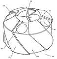
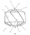
- FIG. 4is a perspective view of a second embodiment
- FIG. 5is a side view of the second embodiment shown in FIG. 4 ;
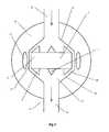
- FIG. 6is a cross-sectional view of the second embodiment
- FIG. 7shows an exploded perspective view of the second embodiment
- FIG. 8shows an enlarged and rotated view of a portion of the second embodiment.
- the pump assembliesaccording to various preferred embodiments to be described below, all have particular, although not exclusive, application for implantation within a patient.
- these pump assembliesmay be used to reduce the pumping load on a patient's heart to which the pumping assembly is connected.
- the preferred embodiments of the present inventionmay be performed by placing the blood pump entirely within the patient's body and connecting the pump between the apex of the left ventricle of the patient's heart and the ascending aorta so as to assist left side heart function. It may also be connected to other regions of the patient's circulation system including: the right side of the heart and/or distal regions of a patient such as the femoral arteries or limbs.
- the blood pump 15includes an impeller 5 which is fully sealed within the pump body or housing 23 .
- the impeller 5has five spaced apart blades 4 , extending from a central shaft 1 , and connected to a support ring 2 .
- the impeller 5is urged to rotate, in use, by an electric motor.
- the electric motormay include several sets of electrical coils or stators 17 mounted on or about the housing 23 and a plurality of permanent magnets 7 embedded or encased within the blades 4 of the impeller 5 .
- the electric coilssequentially energise and exert an electromagnetic force on the impeller 5 and the permanent magnets 7 . If the pump is properly configured, the sequential energising of the electric coils or stators 17 will cause the impeller 5 to rotate.
- the electric coils or stators 17may be mounted in an axial and/or radial orientation, in relation to the axis of rotation of the impeller.
- the support ring 2has a generally rectangular cross section excluding the portions which form the hydrodynamic bearings 3 .
- the generally rectangular cross sectionallows square or rectangular cross-section permanent magnets 7 to be easily inserted within the support ring 2 .
- the benefitis that it is easier to manufacture magnets in a square or rectangular cross-section shape than more complex shapes as provided by in the prior art.
- the support ring 2may also be of hollow construction to minimise weight and/or to reduce complexity of construction.
- the impeller 5includes four hydrodynamic bearings 3 .
- the surface of hydrodynamic bearings 3is generally angled between 0° and 90° relative to the axis of rotation so as to cooperate with an inner surface of the housing 23 to generate a hydrodynamic force away from the inner surface of the cavity 14 .
- the combined effect of these hydrodynamic bearings 3is to hydrodynamically suspend the impeller 5 within the housing 23 , when in use.
- the most preferred angle for the hydrodynamic bearings 3is approximately 45°.
- These hydrodynamic bearings 3produce axial and radial component vectors.
- the hydrodynamic bearings 3supply at least an axial component vector to suspend the impeller 5 in an axial direction, which is generally parallel to the axis of rotation of the impeller 5 .
- the hydrodynamic bearings 3are mounted on the upper surface and the lower surface of the support ring 2 . These hydrodynamic bearings 3 provide a zero net thrust force which is capable of hydrodynamically suspending the impeller 5 in the pump housing 23 , when in use.
- the hydrodynamic bearings 3may also be used in conjunction with other bearings means such as magnetic bearings.
- the blood pump 15includes an inlet 22 and an outlet 21 formed in housing 23 . Between the inlet 22 and the outlet 21 is pumping cavity 14 , which allows fluid communication throughout the pump, when in use. Impeller 5 rotates within cavity 14 and its blades 4 supply pumping motion to the blood, to be pumped when in use.
- the housing 23includes machined surface on the wall of the cavity 14 .
- This machined surfacemay include an upper inner surface 12 , middle inner surface 13 and a lower inner surface 26 .
- the upper inner surface 12 , middle inner surface 13 and/or the lower inner surface 26cooperate with at least a portion of outer surfaces of the impeller 5 to form, in effect, hydrodynamic bearings 3 .
- these portions of the surfacesinclude the outer surface of the support ring 2 and/or the hydrodynamic bearings 3 mounted on the support ring 2 .
- the hydrodynamic bearings 3When impeller 5 is rotated, the hydrodynamic bearings 3 may preferably cooperate with a proximate portion of the angular inner surfaces 12 & 26 of the cavity 14 . Thereby, when blood passes through a gap 20 located between the hydrodynamic bearing 3 and inner surface 26 of the cavity 14 , the impeller 5 experiences a hydrodynamic thrust force. This thrust force acts upon the impeller 5 in a direction away from the inner walls of the housing 23 . The net force of all of the hydrodynamic bearings 3 may result in the impeller 5 being partially or exclusively hydrodynamically suspended within the cavity 14 .
- the blood pump 15 of the first embodimentis in an axial flow configuration.
- the impeller 5in use, is magnetically urged to rotate by the electro-magnetic interaction between permanent magnets 7 embedded or encased within the support ring 2 and the electromagnetic coils forming stators 17 mounted in a radial orientation in respect the axis of rotation of the impeller 5 .
- there are three electric coils forming stators 17however the number of coils may be amended without generally affecting the functionality of this embodiment, so long as there are at least two coils. It should be noted that other coil configurations may also be used and these configurations may include axial mounting configurations.
- the hydrodynamic bearings 3have a generally wedge shaped side profile so as to generate a hydrodynamic force when rotated within the complementary shaped cavity 14 . Please note that the number and size of the hydrodynamic bearings 3 may be also amended without departing from the scope of the present invention.
- Other configurations of hydrodynamic bearings 3may include one hydrodynamic bearing mounted on each side of the impeller 15 and the bearing may run along the entire length of the support ring 2 .
- the hydrodynamic bearings 3may be constructed to balance the hydrodynamic thrust forces and to suspend the impeller 5 away from the inner surfaces of the cavity 14 .
- the impeller 5includes at least an axial and a radial component to the hydrodynamic thrust force generated by the angular surface of the hydrodynamic bearings 3 .
- the hydrodynamic force impartedacts simultaneously in both an axial and radial direction with respect to the orientation of the impeller 5 .
- the impeller of the preferred embodimentsmay include at least some amount of dimensional stability to prevent the blades and/or impeller changing their shape or configuration, in situ. Small dimensional changes in the shape or configuration of impeller 5 or housing 23 may occur due to warping or twisting through regularly use of the pump. Dimensional stability is generally increased or improved by the inclusion of support structures particularly in regard to the impeller 5 . These support structures may include the support ring 2 .
- the impeller 5may also include increased dimensional stability, which is supplied by the generally square or rectangular cross-section of the support ring 2 .
- the support ring 2is joined to the blades 4 in this configuration to prevent or limit the amount or severity of twisting, warping and/or other undesirable dimensional deformation.
- the shaft 1is preferably centered within the periphery of the impeller 5 and is orientated in an axial direction.
- the blades 4 of this first embodimentare generally thin and arcuate in shape and may incorporate features to minimise drag and/or shear forces.
- the first embodimentpreferably operates at speeds of between 1500 rpm to 4000 rpm.
- the preferred outer blade diameteris 40 mm
- outer housing average diameteris 60 mm
- the housing axial lengthis 44 mm.
- FIGS. 4 , 5 , 6 , 7 & 8a second embodiment of the present invention is shown.
- An impeller 104is provided for by the embodiment and includes a central shaft 103 and a support ring 114 . Extending from the internal or interior surface of the support ring 114 towards the centre of the pump 110 are a plurality or set of blades 105 . In this preferred embodiment, three blades comprise the said blade set 105 . However any number of individual blades may be used to construct the blade set 105 .
- the blades 105fully extends from the support ring 114 to abut against the central shaft 103 .
- the support ring 114preferably includes: two sets of permanent magnets 102 & 115 ; hydrodynamic bearing surfaces 101 and channels 106 formed between the hydrodynamic bearing surfaces 101 .
- the upper set of permanent magnets 102extend from the base of the channels 106 in the upper surface into the support ring 114 .
- the upper set of permanent magnets 102comprise four permanent magnets aligned as to have the northern pole of the magnets facing up.
- the upper set of permanent magnets 102extends almost throughout the entire width of the support ring 114 without interfering with the hydrodynamic bearing surface 101 on the lower side of the support ring 114 .
- the lower set of permanent magnets 115works in an inverse manner to the upper set of permanent magnets 102 .
- the northern pole of the lower set of permanent magnets 115faces downwards.
- the permanent magnetsare disposed alternately in respect of polarity and are spaced at 45° intervals.
- the permanent magnets 102 & 115are jacketed beneath a thin layer of impermeable biocompatible material to prevent corrosion or bio-toxic leaking.
- This embodimentincludes an impeller 104 , which is designed to be rotated clockwise, with four hydrodynamic bearing surfaces 101 .
- the hydrodynamic bearing surface 101forms a pad which covers the upper face of the support ring 114 and extends downwardly and at an anti-clockwise angle to the lower face of the support ring 114 .
- the angular extension 107 of the hydrodynamic bearing surface 101may generate a hydrodynamic bearing that is capable of acting at least axially and/or radially in respect of the axis of rotation of the impeller 104 .
- the hydrodynamic bearingmay also act in respect of other degrees of freedom.
- Each hydrodynamic bearing surface 101includes a leading edge and a trailing edge.
- the leading edgeis the edge that leads the trailing edge when the impeller is rotated in a clockwise direction.
- the leading edgeis 50 ⁇ m lower than the trailing edge.
- the angularly surfacecooperates with the interior of the pump housing to form a restriction. This restriction generates a thrust force perpendicular to the bearing surface.
- the hydrodynamic bearingssuspend the impeller 104 within the pump housing 120 .
- the hydrodynamic bearing surfaces 101have a generally wedge shaped appearance.
- the channels 106are approximately 0.5 mm deeper than the leading edge of the hydrodynamic bearing. This channel 106 may allow retrograde blood flow over the surface of the impeller 104 , when in use. This is described in greater detail further on in this specification.
- the pump 110pumps blood from the inlet 108 to the outlet 109 by the rotation of impeller 104 , which in turn rotates a plurality of blades 105 .
- the impelleris mounted within an upper 120 and lower housing 119 .
- the housings 120 & 119are preferably joined by laser welding at location 117 .
- the impeller 104is urged to rotate magnetically through the synchronised activation of the stators 112 cooperating with the permanent magnets 102 .
- the preferred speed of rotation of impeller 104is approximately 2,000 rpm. However, it will be appreciated that small changes in shape and diameter of impeller 104 will greatly effect the preferred speed of rotation.
- the internal portions of the pump 110are encapsulated within a casing shell 111 and two end caps 126 .
- the end caps 126 and casing shell 111may be constructed of a biocompatible Titanium alloy which may be joined and sealed by laser welding. It includes a casing shell hole 127 to allow access to the interior of the pump by electronic leads for pump control, power and data.
- Each blade 105forms a screw thread configuration around the central shaft 103 .
- the pitch of the screw thread of the individual bladesdecreases as the blade extends away form the inlet of the pump 110 . This allows some the torsional force applied to the blood being pumped to be translated into thrust in the direction of the outlet and straightens the flow of blood leaving the pump.
- using this type of configurationmay reduce or eliminate the need for flow straighteners in the outflow of the pump 110 .
- the retrograde blood flow in the pump 110has an elevated pressure in outlet 109 when compared to the pressure level in the inlet 108 as a result of the rotation of impeller 104 .
- the pressure differential created between the outlet 109 and inlet 104means that blood will, where possible, attempt to flow back to the inlet 104 .
- the bloodis purposively given an opportunity to do this by the gap 113 which occurs between the outermost surface of the impeller 104 and the innermost surface of the housings 119 & 120 , which forms a cavity 116 for the impeller 104 to rotate within.
- the gap 113is the location where a hydrodynamic bearing is created by the interaction of the hydrodynamic bearing surfaces 101 and the walls of the cavity 116 .
- the gap 113is approximately 80 ⁇ m.
- the gap 113is preferably small enough so as exclude a majority of blood cells from this area by fluid forces. This exclusion of red blood cells reduces haemolysis caused by the bearing forces. Additionally, the constant flow of fresh blood across the outermost surfaces of the impeller 104 reduces the chance or likelihood of thrombogenesis in the vicinity of the impeller 104 .
- the stators 112are in an axial configuration around the impeller 104 and are formed from twelve independent coils mounted directly onto a printed circuit board 118 .
- the coilsare inserted within twelve wells 125 formed in the outer surface of the housing 120 .
- the printed circuit board 118forms part of the control system for the pump 110 and is backed by an iron metal yoke to improve EMF efficiency.
- the twelve stator coilsare shown at one instance in time when the coils are firing to urge the impeller 104 .
- the twelve stator coilsare depicted in three groups 121 , 122 & 123 .
- the three groups of coils 121 , 122 , & 123cooperate with the permanent magnets 102 & 115 of the impeller 104 to rotate it.
- the first group of coils 121have their north poles distal from the printed circuit board 118 .
- the second group of coils 123have an inverted polarity and the third polarity is not charged.
- the charging sequence of the groups of coils 121 , 122 , & 123rotates clockwise and induces the rotation of the impeller 104 .
Landscapes
- Health & Medical Sciences (AREA)
- Heart & Thoracic Surgery (AREA)
- Engineering & Computer Science (AREA)
- Cardiology (AREA)
- Life Sciences & Earth Sciences (AREA)
- Public Health (AREA)
- Biomedical Technology (AREA)
- Hematology (AREA)
- Mechanical Engineering (AREA)
- Animal Behavior & Ethology (AREA)
- General Health & Medical Sciences (AREA)
- Anesthesiology (AREA)
- Veterinary Medicine (AREA)
- Physics & Mathematics (AREA)
- Fluid Mechanics (AREA)
- External Artificial Organs (AREA)
- Structures Of Non-Positive Displacement Pumps (AREA)
- Sliding-Contact Bearings (AREA)
Abstract
Description
Claims (20)
Applications Claiming Priority (3)
| Application Number | Priority Date | Filing Date | Title |
|---|---|---|---|
| AU2003905511 | 2003-10-09 | ||
| AU2003905511AAU2003905511A0 (en) | 2003-10-09 | Impeller | |
| PCT/AU2004/001379WO2005032620A1 (en) | 2003-10-09 | 2004-10-08 | Impeller |
Related Parent Applications (1)
| Application Number | Title | Priority Date | Filing Date |
|---|---|---|---|
| PCT/AU2004/001379A-371-Of-InternationalWO2005032620A1 (en) | 2003-10-09 | 2004-10-08 | Impeller |
Related Child Applications (1)
| Application Number | Title | Priority Date | Filing Date |
|---|---|---|---|
| US12/860,847ContinuationUS8366599B2 (en) | 2003-10-09 | 2010-08-20 | Axial flow blood pump |
Publications (2)
| Publication Number | Publication Date |
|---|---|
| US20070276480A1 US20070276480A1 (en) | 2007-11-29 |
| US7798952B2true US7798952B2 (en) | 2010-09-21 |
Family
ID=34397675
Family Applications (2)
| Application Number | Title | Priority Date | Filing Date |
|---|---|---|---|
| US10/575,118Expired - Fee RelatedUS7798952B2 (en) | 2003-10-09 | 2004-10-08 | Axial flow blood pump |
| US12/860,847Expired - Fee RelatedUS8366599B2 (en) | 2003-10-09 | 2010-08-20 | Axial flow blood pump |
Family Applications After (1)
| Application Number | Title | Priority Date | Filing Date |
|---|---|---|---|
| US12/860,847Expired - Fee RelatedUS8366599B2 (en) | 2003-10-09 | 2010-08-20 | Axial flow blood pump |
Country Status (5)
| Country | Link |
|---|---|
| US (2) | US7798952B2 (en) |
| EP (1) | EP1670524A4 (en) |
| JP (2) | JP4889492B2 (en) |
| CA (1) | CA2541979A1 (en) |
| WO (1) | WO2005032620A1 (en) |
Cited By (28)
| Publication number | Priority date | Publication date | Assignee | Title |
|---|---|---|---|---|
| US20110311383A1 (en)* | 2010-06-18 | 2011-12-22 | White Daniel G | Hydrodynamic chamfer thrust bearing |
| US8690749B1 (en) | 2009-11-02 | 2014-04-08 | Anthony Nunez | Wireless compressible heart pump |
| US8864643B2 (en) | 2011-10-13 | 2014-10-21 | Thoratec Corporation | Pump and method for mixed flow blood pumping |
| US8894561B2 (en) | 2012-03-05 | 2014-11-25 | Thoratec Corporation | Modular implantable medical pump |
| US9089634B2 (en) | 2009-09-22 | 2015-07-28 | Ecp Entwicklungsgesellschaft Mbh | Fluid pump having at least one impeller blade and a support device |
| US9144638B2 (en) | 2013-03-14 | 2015-09-29 | Thoratec Corporation | Blood pump rotor bearings |
| US9265870B2 (en) | 2010-10-13 | 2016-02-23 | Thoratec Corporation | Pumping blood |
| US9827357B2 (en) | 2011-12-03 | 2017-11-28 | Indiana University Research And Technology Corporation | Cavopulmonary viscous impeller assist device and method |
| US10524830B2 (en) | 2012-12-27 | 2020-01-07 | Tc1 Llc | Surgical tunneler |
| US10660998B2 (en) | 2016-08-12 | 2020-05-26 | Tci Llc | Devices and methods for monitoring bearing and seal performance |
| US10724534B2 (en) | 2014-11-26 | 2020-07-28 | Tc1 Llc | Pump and method for mixed flow blood pumping |
| US10857273B2 (en) | 2016-07-21 | 2020-12-08 | Tc1 Llc | Rotary seal for cantilevered rotor pump and methods for axial flow blood pumping |
| US20210015982A1 (en)* | 2018-03-23 | 2021-01-21 | Abiomed Europe Gmbh | Intravascular blood pump with ceramic inner sleeve |
| WO2021257347A1 (en) | 2020-06-17 | 2021-12-23 | Tc1 Llc | Extracorporeal blood pump assembly and methods of assembling same |
| US11368081B2 (en) | 2018-01-24 | 2022-06-21 | Kardion Gmbh | Magnetic coupling element with a magnetic bearing function |
| US11632015B2 (en) | 2018-08-28 | 2023-04-18 | Boston Scientific Scimed, Inc. | Axial flux motor for percutaneous circulatory support device |
| US11754075B2 (en) | 2018-07-10 | 2023-09-12 | Kardion Gmbh | Impeller for an implantable, vascular support system |
| US11944805B2 (en) | 2020-01-31 | 2024-04-02 | Kardion Gmbh | Pump for delivering a fluid and method of manufacturing a pump |
| US12005248B2 (en) | 2018-05-16 | 2024-06-11 | Kardion Gmbh | Rotor bearing system |
| US12064615B2 (en) | 2018-05-30 | 2024-08-20 | Kardion Gmbh | Axial-flow pump for a ventricular assist device and method for producing an axial-flow pump for a ventricular assist device |
| US12076549B2 (en) | 2018-07-20 | 2024-09-03 | Kardion Gmbh | Feed line for a pump unit of a cardiac assistance system, cardiac assistance system and method for producing a feed line for a pump unit of a cardiac assistance system |
| US12107474B2 (en) | 2018-05-16 | 2024-10-01 | Kardion Gmbh | End-face rotating joint for transmitting torques |
| US12144976B2 (en) | 2018-06-21 | 2024-11-19 | Kardion Gmbh | Method and device for detecting a wear condition of a ventricular assist device and for operating same, and ventricular assist device |
| US12194287B2 (en) | 2018-05-30 | 2025-01-14 | Kardion Gmbh | Method of manufacturing electrical conductor tracks in a region of an intravascular blood pump |
| US12201823B2 (en) | 2018-05-30 | 2025-01-21 | Kardion Gmbh | Line device for conducting a blood flow for a heart support system, heart support system, and method for producing a line device |
| US12263333B2 (en) | 2018-06-21 | 2025-04-01 | Kardion Gmbh | Stator vane device for guiding the flow of a fluid flowing out of an outlet opening of a ventricular assist device, ventricular assist device with stator vane device, method for operating a stator vane device and manufacturing method |
| US12383727B2 (en) | 2018-05-30 | 2025-08-12 | Kardion Gmbh | Motor housing module for a heart support system, and heart support system and method for mounting a heart support system |
| US12390633B2 (en) | 2018-08-07 | 2025-08-19 | Kardion Gmbh | Bearing device for a heart support system, and method for rinsing a space in a bearing device for a heart support system |
Families Citing this family (63)
| Publication number | Priority date | Publication date | Assignee | Title |
|---|---|---|---|---|
| US8419609B2 (en) | 2005-10-05 | 2013-04-16 | Heartware Inc. | Impeller for a rotary ventricular assist device |
| WO2007040663A1 (en)* | 2005-10-05 | 2007-04-12 | Heartware, Inc. | Axial flow pump with multi-grooved rotor |
| CA2627164C (en)* | 2005-11-02 | 2014-06-17 | Prosthesica Ag | Artificial valve for implantation |
| AU2008219653B2 (en) | 2007-02-26 | 2014-01-16 | Heartware, Inc. | Intravascular ventricular assist device |
| CN101715352B (en) | 2007-06-14 | 2013-11-06 | 卡龙心脏科技有限公司 | Reduced diameter axial rotary pump for cardiac assist |
| EP2194278A1 (en) | 2008-12-05 | 2010-06-09 | ECP Entwicklungsgesellschaft mbH | Fluid pump with a rotor |
| EP2216059A1 (en) | 2009-02-04 | 2010-08-11 | ECP Entwicklungsgesellschaft mbH | Catheter device with a catheter and an actuation device |
| EP2229965A1 (en) | 2009-03-18 | 2010-09-22 | ECP Entwicklungsgesellschaft mbH | Fluid pump with particular form of a rotor blade |
| EP2246078A1 (en) | 2009-04-29 | 2010-11-03 | ECP Entwicklungsgesellschaft mbH | Shaft assembly with a shaft which moves within a fluid-filled casing |
| EP2248544A1 (en) | 2009-05-05 | 2010-11-10 | ECP Entwicklungsgesellschaft mbH | Fluid pump with variable circumference, particularly for medical use |
| EP2266640A1 (en) | 2009-06-25 | 2010-12-29 | ECP Entwicklungsgesellschaft mbH | Compressible and expandable turbine blade for a fluid pump |
| EP2453843B1 (en) | 2009-07-17 | 2015-09-30 | Kirk Promotion LTD. | Artificial valve for implantation |
| EP2282070B1 (en) | 2009-08-06 | 2012-10-17 | ECP Entwicklungsgesellschaft mbH | Catheter device with a coupling device for a drive device |
| EP2299119B1 (en) | 2009-09-22 | 2018-11-07 | ECP Entwicklungsgesellschaft mbH | Inflatable rotor for a fluid pump |
| EP2298371A1 (en) | 2009-09-22 | 2011-03-23 | ECP Entwicklungsgesellschaft mbH | Function element, in particular fluid pump with a housing and a transport element |
| EP2298372A1 (en) | 2009-09-22 | 2011-03-23 | ECP Entwicklungsgesellschaft mbH | Rotor for an axial pump for transporting a fluid |
| EP2314331B1 (en) | 2009-10-23 | 2013-12-11 | ECP Entwicklungsgesellschaft mbH | Catheter pump arrangement and flexible shaft arrangement with a cable core |
| EP2314330A1 (en) | 2009-10-23 | 2011-04-27 | ECP Entwicklungsgesellschaft mbH | Flexible shaft arrangement |
| EP2338539A1 (en) | 2009-12-23 | 2011-06-29 | ECP Entwicklungsgesellschaft mbH | Pump device with a detection device |
| EP2338540A1 (en) | 2009-12-23 | 2011-06-29 | ECP Entwicklungsgesellschaft mbH | Delivery blade for a compressible rotor |
| EP2338541A1 (en) | 2009-12-23 | 2011-06-29 | ECP Entwicklungsgesellschaft mbH | Radial compressible and expandable rotor for a fluid pump |
| EP2347778A1 (en) | 2010-01-25 | 2011-07-27 | ECP Entwicklungsgesellschaft mbH | Fluid pump with a radially compressible rotor |
| EP2363157A1 (en) | 2010-03-05 | 2011-09-07 | ECP Entwicklungsgesellschaft mbH | Device for exerting mechanical force on a medium, in particular fluid pump |
| JP5572832B2 (en)* | 2010-03-26 | 2014-08-20 | ソーラテック コーポレイション | Centrifugal blood pump device |
| EP2388029A1 (en) | 2010-05-17 | 2011-11-23 | ECP Entwicklungsgesellschaft mbH | Pump array |
| EP2399639A1 (en) | 2010-06-25 | 2011-12-28 | ECP Entwicklungsgesellschaft mbH | System for introducing a pump |
| EP2407187A3 (en) | 2010-07-15 | 2012-06-20 | ECP Entwicklungsgesellschaft mbH | Blood pump for invasive application within the body of a patient |
| EP2407185A1 (en) | 2010-07-15 | 2012-01-18 | ECP Entwicklungsgesellschaft mbH | Radial compressible and expandable rotor for a pump with a turbine blade |
| EP2407186A1 (en) | 2010-07-15 | 2012-01-18 | ECP Entwicklungsgesellschaft mbH | Rotor for a pump, produced with an initial elastic material |
| EP2605809B1 (en) | 2010-08-20 | 2017-10-11 | Tc1 Llc | Implantable blood pump |
| EP2422735A1 (en) | 2010-08-27 | 2012-02-29 | ECP Entwicklungsgesellschaft mbH | Implantable blood transportation device, manipulation device and coupling device |
| US8794989B2 (en)* | 2010-12-08 | 2014-08-05 | Thoratec Corporation | Modular driveline |
| EP2497521A1 (en) | 2011-03-10 | 2012-09-12 | ECP Entwicklungsgesellschaft mbH | Push device for axial insertion of a string-shaped, flexible body |
| EP2564771A1 (en) | 2011-09-05 | 2013-03-06 | ECP Entwicklungsgesellschaft mbH | Medicinal product with a functional element for invasive use in the body of a patient |
| US8926492B2 (en) | 2011-10-11 | 2015-01-06 | Ecp Entwicklungsgesellschaft Mbh | Housing for a functional element |
| US10342905B2 (en) | 2012-09-13 | 2019-07-09 | Circulite, Inc. | Blood flow system with variable speed control |
| WO2014106885A1 (en) | 2013-01-07 | 2014-07-10 | 国立大学法人神戸大学 | Axial flow blood pump |
| WO2015017770A1 (en) | 2013-08-02 | 2015-02-05 | Circulite, Inc. | Implantable system with secure remote control |
| EP3200846B1 (en) | 2014-10-01 | 2020-01-15 | Heartware, Inc. | Backup controller system with updating |
| US9717832B2 (en) | 2015-01-06 | 2017-08-01 | HeartWave, Inc. | Axial flow rotor with downstream bearing wash flow |
| WO2017004175A1 (en) | 2015-06-29 | 2017-01-05 | Thoratec Corporation | Ventricular assist devices having a hollow rotor and methods of use |
| US10177627B2 (en) | 2015-08-06 | 2019-01-08 | Massachusetts Institute Of Technology | Homopolar, flux-biased hysteresis bearingless motor |
| EP3173110A1 (en) | 2015-11-30 | 2017-05-31 | Fundacja Rozwoju Kardiochirurgii Im. Prof. Zbigniewa Religi | Rotary pump suspension system arrangement, especially of implantable centrifugal heart assist pump |
| KR101840857B1 (en)* | 2016-03-24 | 2018-03-21 | 서울대학교 산학협력단 | Blood pump |
| WO2017173217A1 (en)* | 2016-04-01 | 2017-10-05 | Heartware, Inc. | Axial flow blood pump with radially offset rotor |
| WO2017196271A1 (en) | 2016-05-13 | 2017-11-16 | Koc Universitesi | Internal axial flow blood pump with passive magnets and hydrodynamic radial bearing |
| CA3066361A1 (en) | 2017-06-07 | 2018-12-13 | Shifamed Holdings, Llc | Intravascular fluid movement devices, systems, and methods of use |
| EP3456367A1 (en)* | 2017-09-19 | 2019-03-20 | Abiomed Europe GmbH | Blood pump |
| WO2019094963A1 (en) | 2017-11-13 | 2019-05-16 | Shifamed Holdings, Llc | Intravascular fluid movement devices, systems, and methods of use |
| US10833570B2 (en) | 2017-12-22 | 2020-11-10 | Massachusetts Institute Of Technology | Homopolar bearingless slice motors |
| EP3737435B1 (en) | 2018-01-10 | 2023-10-18 | Tc1 Llc | Bearingless implantable blood pump |
| CN112004563B (en) | 2018-02-01 | 2024-08-06 | 施菲姆德控股有限责任公司 | Intravascular blood pump and methods of use and manufacture |
| AU2019315428B2 (en)* | 2018-07-30 | 2024-06-20 | Michael SIEGENTHALER | Open electric pump |
| US12161857B2 (en) | 2018-07-31 | 2024-12-10 | Shifamed Holdings, Llc | Intravascular blood pumps and methods of use |
| WO2020073047A1 (en) | 2018-10-05 | 2020-04-09 | Shifamed Holdings, Llc | Intravascular blood pumps and methods of use |
| WO2021011473A1 (en) | 2019-07-12 | 2021-01-21 | Shifamed Holdings, Llc | Intravascular blood pumps and methods of manufacture and use |
| US11654275B2 (en) | 2019-07-22 | 2023-05-23 | Shifamed Holdings, Llc | Intravascular blood pumps with struts and methods of use and manufacture |
| WO2021062265A1 (en) | 2019-09-25 | 2021-04-01 | Shifamed Holdings, Llc | Intravascular blood pump systems and methods of use and control thereof |
| US12121713B2 (en) | 2019-09-25 | 2024-10-22 | Shifamed Holdings, Llc | Catheter blood pumps and collapsible blood conduits |
| EP4501393A3 (en) | 2019-09-25 | 2025-04-09 | Shifamed Holdings, LLC | Catheter blood pumps and collapsible pump housings |
| EP4072650A4 (en) | 2019-12-11 | 2024-01-10 | Shifamed Holdings, LLC | Descending aorta and vena cava blood pumps |
| CN112472999B (en) | 2020-12-22 | 2025-03-21 | 深圳核心医疗科技股份有限公司 | Blood Pump |
| DE102021125982A1 (en) | 2021-10-06 | 2023-04-06 | Nidec Gpm Gmbh | Axial pump with axial flow motor |
Citations (50)
| Publication number | Priority date | Publication date | Assignee | Title |
|---|---|---|---|---|
| US4382199A (en) | 1980-11-06 | 1983-05-03 | Nu-Tech Industries, Inc. | Hydrodynamic bearing system for a brushless DC motor |
| US4688998A (en) | 1981-03-18 | 1987-08-25 | Olsen Don B | Magnetically suspended and rotated impellor pump apparatus and method |
| US4817586A (en) | 1987-11-24 | 1989-04-04 | Nimbus Medical, Inc. | Percutaneous bloom pump with mixed-flow output |
| US4906226A (en) | 1989-08-08 | 1990-03-06 | Hecker Charles R | Attachable fan belt |
| US4944748A (en) | 1986-10-12 | 1990-07-31 | Bramm Gunter W | Magnetically suspended and rotated rotor |
| US4995857A (en) | 1989-04-07 | 1991-02-26 | Arnold John R | Left ventricular assist device and method for temporary and permanent procedures |
| US5055005A (en) | 1990-10-05 | 1991-10-08 | Kletschka Harold D | Fluid pump with levitated impeller |
| US5078741A (en) | 1986-10-12 | 1992-01-07 | Life Extenders Corporation | Magnetically suspended and rotated rotor |
| US5112200A (en) | 1990-05-29 | 1992-05-12 | Nu-Tech Industries, Inc. | Hydrodynamically suspended rotor axial flow blood pump |
| WO1992015239A1 (en) | 1991-02-04 | 1992-09-17 | Kensey Nash Corporation | Apparatus and method for determining viscosity of the blood of a living being |
| US5195877A (en) | 1990-10-05 | 1993-03-23 | Kletschka Harold D | Fluid pump with magnetically levitated impeller |
| US5211546A (en) | 1990-05-29 | 1993-05-18 | Nu-Tech Industries, Inc. | Axial flow blood pump with hydrodynamically suspended rotor |
| US5289821A (en) | 1993-06-30 | 1994-03-01 | Swartz William M | Method of ultrasonic Doppler monitoring of blood flow in a blood vessel |
| US5370509A (en) | 1989-05-08 | 1994-12-06 | The Cleveland Clinic Foundation | Sealless rotodynamic pump with fluid bearing |
| US5470208A (en) | 1990-10-05 | 1995-11-28 | Kletschka; Harold D. | Fluid pump with magnetically levitated impeller |
| WO1997029795A1 (en) | 1996-02-20 | 1997-08-21 | Kriton Medical, Inc. | Sealless rotary blood pump with passive magnetic radial bearings and blood immersed axial bearings |
| US5685700A (en) | 1995-06-01 | 1997-11-11 | Advanced Bionics, Inc. | Bearing and seal-free blood pump |
| CA2237203A1 (en) | 1996-09-10 | 1998-03-19 | Sulzer Electronics Ag | Rotary pump and method for operation thereof |
| US5840070A (en)* | 1996-02-20 | 1998-11-24 | Kriton Medical, Inc. | Sealless rotary blood pump |
| US5924848A (en) | 1995-06-01 | 1999-07-20 | Advanced Bionics, Inc. | Blood pump having radial vanes with enclosed magnetic drive components |
| US5938412A (en) | 1995-06-01 | 1999-08-17 | Advanced Bionics, Inc. | Blood pump having rotor with internal bore for fluid flow |
| US6027498A (en) | 1994-03-15 | 2000-02-22 | University Of Manitoba | Control of life support systems |
| US6066086A (en) | 1996-11-01 | 2000-05-23 | Nimbus, Inc. | Speed control system for implanted blood pumps |
| US6071093A (en) | 1996-10-18 | 2000-06-06 | Abiomed, Inc. | Bearingless blood pump and electronic drive system |
| US6100618A (en) | 1995-04-03 | 2000-08-08 | Sulzer Electronics Ag | Rotary machine with an electromagnetic rotary drive |
| US6120537A (en) | 1997-12-23 | 2000-09-19 | Kriton Medical, Inc. | Sealless blood pump with means for avoiding thrombus formation |
| US6158984A (en) | 1998-12-28 | 2000-12-12 | Kriton Medical, Inc. | Rotary blood pump with ceramic members |
| US6171078B1 (en) | 1997-09-04 | 2001-01-09 | Sulzer Electronics Ag | Centrifugal pump |
| WO2001012070A1 (en) | 1999-08-12 | 2001-02-22 | Vascusense, Inc. | Ultrasonic monitoring of cardiac valvular flow condition |
| US6206659B1 (en) | 1995-06-01 | 2001-03-27 | Advanced Bionics, Inc. | Magnetically driven rotor for blood pump |
| US6217541B1 (en) | 1999-01-19 | 2001-04-17 | Kriton Medical, Inc. | Blood pump using cross-flow principles |
| US6227797B1 (en)* | 1997-09-05 | 2001-05-08 | Ventrassist Pty Ltd And University Of Technology | Rotary pump with hydrodynamically suspended impeller |
| US6234772B1 (en) | 1999-04-28 | 2001-05-22 | Kriton Medical, Inc. | Rotary blood pump |
| US6250880B1 (en) | 1997-09-05 | 2001-06-26 | Ventrassist Pty. Ltd | Rotary pump with exclusively hydrodynamically suspended impeller |
| US6264635B1 (en) | 1998-12-03 | 2001-07-24 | Kriton Medical, Inc. | Active magnetic bearing system for blood pump |
| US20010009645A1 (en) | 2000-01-26 | 2001-07-26 | Hiroyuki Noda | Magnetically driven axial-flow pump |
| US6277078B1 (en) | 1999-11-19 | 2001-08-21 | Remon Medical Technologies, Ltd. | System and method for monitoring a parameter associated with the performance of a heart |
| JP2002224066A (en) | 2001-02-01 | 2002-08-13 | Univ Nihon | Cardiac function evaluation device |
| US20020183628A1 (en) | 2001-06-05 | 2002-12-05 | Sanford Reich | Pressure sensing endograft |
| WO2003015609A2 (en) | 2001-08-16 | 2003-02-27 | Apex Medical, Inc. | Physiological heart pump control |
| EP1354606A1 (en) | 2002-04-19 | 2003-10-22 | Thoratec Corporation | Adaptive speed control for blood pump |
| WO2004028593A1 (en) | 2002-09-30 | 2004-04-08 | Ventrassist Pty Ltd | Physiological demand responsive control system |
| US20040084398A1 (en) | 2000-08-03 | 2004-05-06 | Klaus Breitschwerdt | Module, especially a wafer module |
| US20040084399A1 (en) | 2002-05-28 | 2004-05-06 | Shipley Company, L.L.C. | Process of producing printed circuit boards and the circuit boards formed thereby |
| JP2004278375A (en) | 2003-03-14 | 2004-10-07 | Yasuhiro Fukui | Axial flow pump |
| US6866625B1 (en) | 1999-04-23 | 2005-03-15 | Ventrassist Pty Ltd | Rotary blood pump and control system therefor |
| US7052253B2 (en) | 2003-05-19 | 2006-05-30 | Advanced Bionics, Inc. | Seal and bearing-free fluid pump incorporating a passively suspended self-positioning impeller |
| US7070398B2 (en) | 2003-09-25 | 2006-07-04 | Medforte Research Foundation | Axial-flow blood pump with magnetically suspended, radially and axially stabilized impeller |
| US20070231135A1 (en) | 2006-03-31 | 2007-10-04 | Orqis Medical Corporation | Rotary Blood Pump |
| US20080080983A1 (en) | 2003-09-18 | 2008-04-03 | Wampler Richard K | Rotary Blood Pump With Opposing Spindle Magnets, Bore And Drive Windings |
Family Cites Families (5)
| Publication number | Priority date | Publication date | Assignee | Title |
|---|---|---|---|---|
| US5205721A (en)* | 1991-02-13 | 1993-04-27 | Nu-Tech Industries, Inc. | Split stator for motor/blood pump |
| CA2370755C (en)* | 1999-04-23 | 2009-11-24 | Peter Joseph Ayre | A rotary blood pump and control system therefor |
| US6527699B1 (en)* | 2000-06-02 | 2003-03-04 | Michael P. Goldowsky | Magnetic suspension blood pump |
| JP2002070780A (en)* | 2000-09-01 | 2002-03-08 | Toshiba Corp | Axial pump and reactor incorporating this pump |
| JP2002349482A (en)* | 2001-05-24 | 2002-12-04 | National Institute Of Advanced Industrial & Technology | Centrifugal pump for artificial heart |
- 2004
- 2004-10-08EPEP04761412Apatent/EP1670524A4/ennot_activeWithdrawn
- 2004-10-08JPJP2006529462Apatent/JP4889492B2/ennot_activeExpired - Fee Related
- 2004-10-08WOPCT/AU2004/001379patent/WO2005032620A1/enactiveApplication Filing
- 2004-10-08USUS10/575,118patent/US7798952B2/ennot_activeExpired - Fee Related
- 2004-10-08CACA002541979Apatent/CA2541979A1/ennot_activeAbandoned
- 2010
- 2010-02-12JPJP2010029252Apatent/JP2010158532A/enactivePending
- 2010-08-20USUS12/860,847patent/US8366599B2/ennot_activeExpired - Fee Related
Patent Citations (64)
| Publication number | Priority date | Publication date | Assignee | Title |
|---|---|---|---|---|
| US4382199A (en) | 1980-11-06 | 1983-05-03 | Nu-Tech Industries, Inc. | Hydrodynamic bearing system for a brushless DC motor |
| US4688998A (en) | 1981-03-18 | 1987-08-25 | Olsen Don B | Magnetically suspended and rotated impellor pump apparatus and method |
| US5385581A (en) | 1982-04-04 | 1995-01-31 | Life Extenders Corporation | Magnetically suspended and rotated rotor |
| US5326344A (en) | 1985-04-04 | 1994-07-05 | Life Extenders Corporation | Magnetically suspended and rotated rotor |
| US4944748A (en) | 1986-10-12 | 1990-07-31 | Bramm Gunter W | Magnetically suspended and rotated rotor |
| US5078741A (en) | 1986-10-12 | 1992-01-07 | Life Extenders Corporation | Magnetically suspended and rotated rotor |
| US4817586A (en) | 1987-11-24 | 1989-04-04 | Nimbus Medical, Inc. | Percutaneous bloom pump with mixed-flow output |
| US4995857A (en) | 1989-04-07 | 1991-02-26 | Arnold John R | Left ventricular assist device and method for temporary and permanent procedures |
| US5370509A (en) | 1989-05-08 | 1994-12-06 | The Cleveland Clinic Foundation | Sealless rotodynamic pump with fluid bearing |
| US4906226A (en) | 1989-08-08 | 1990-03-06 | Hecker Charles R | Attachable fan belt |
| US5112200A (en) | 1990-05-29 | 1992-05-12 | Nu-Tech Industries, Inc. | Hydrodynamically suspended rotor axial flow blood pump |
| US5211546A (en) | 1990-05-29 | 1993-05-18 | Nu-Tech Industries, Inc. | Axial flow blood pump with hydrodynamically suspended rotor |
| US5470208A (en) | 1990-10-05 | 1995-11-28 | Kletschka; Harold D. | Fluid pump with magnetically levitated impeller |
| US5195877A (en) | 1990-10-05 | 1993-03-23 | Kletschka Harold D | Fluid pump with magnetically levitated impeller |
| US5055005A (en) | 1990-10-05 | 1991-10-08 | Kletschka Harold D | Fluid pump with levitated impeller |
| WO1992015239A1 (en) | 1991-02-04 | 1992-09-17 | Kensey Nash Corporation | Apparatus and method for determining viscosity of the blood of a living being |
| US5289821A (en) | 1993-06-30 | 1994-03-01 | Swartz William M | Method of ultrasonic Doppler monitoring of blood flow in a blood vessel |
| US6027498A (en) | 1994-03-15 | 2000-02-22 | University Of Manitoba | Control of life support systems |
| US6100618A (en) | 1995-04-03 | 2000-08-08 | Sulzer Electronics Ag | Rotary machine with an electromagnetic rotary drive |
| US5938412A (en) | 1995-06-01 | 1999-08-17 | Advanced Bionics, Inc. | Blood pump having rotor with internal bore for fluid flow |
| US5685700A (en) | 1995-06-01 | 1997-11-11 | Advanced Bionics, Inc. | Bearing and seal-free blood pump |
| US6206659B1 (en) | 1995-06-01 | 2001-03-27 | Advanced Bionics, Inc. | Magnetically driven rotor for blood pump |
| US5924848A (en) | 1995-06-01 | 1999-07-20 | Advanced Bionics, Inc. | Blood pump having radial vanes with enclosed magnetic drive components |
| WO1997029795A1 (en) | 1996-02-20 | 1997-08-21 | Kriton Medical, Inc. | Sealless rotary blood pump with passive magnetic radial bearings and blood immersed axial bearings |
| US5695471A (en) | 1996-02-20 | 1997-12-09 | Kriton Medical, Inc. | Sealless rotary blood pump with passive magnetic radial bearings and blood immersed axial bearings |
| US6080133A (en) | 1996-02-20 | 2000-06-27 | Kriton Medical, Inc. | Sealless rotary blood pump |
| US20040234397A1 (en) | 1996-02-20 | 2004-11-25 | Heartware, Inc. (A Delaware Corporation) | Sealless rotary blood pump |
| US6688861B2 (en) | 1996-02-20 | 2004-02-10 | Heartware, Inc. | Sealless rotary blood pump |
| US6234998B1 (en) | 1996-02-20 | 2001-05-22 | Kriton Medical, Inc. | Sealless rotary blood pump |
| US6368083B1 (en) | 1996-02-20 | 2002-04-09 | Kriton Medical, Inc. | Sealless rotary blood pump |
| US5840070A (en)* | 1996-02-20 | 1998-11-24 | Kriton Medical, Inc. | Sealless rotary blood pump |
| US6053705A (en) | 1996-09-10 | 2000-04-25 | Sulzer Electronics Ag | Rotary pump and process to operate it |
| CA2237203A1 (en) | 1996-09-10 | 1998-03-19 | Sulzer Electronics Ag | Rotary pump and method for operation thereof |
| US6071093A (en) | 1996-10-18 | 2000-06-06 | Abiomed, Inc. | Bearingless blood pump and electronic drive system |
| US6066086A (en) | 1996-11-01 | 2000-05-23 | Nimbus, Inc. | Speed control system for implanted blood pumps |
| US6609883B2 (en) | 1997-05-09 | 2003-08-26 | Ventrassist Pty Ltd | Rotary pump with hydrodynamically suspended impeller |
| US6171078B1 (en) | 1997-09-04 | 2001-01-09 | Sulzer Electronics Ag | Centrifugal pump |
| US6227797B1 (en)* | 1997-09-05 | 2001-05-08 | Ventrassist Pty Ltd And University Of Technology | Rotary pump with hydrodynamically suspended impeller |
| US6966748B2 (en) | 1997-09-05 | 2005-11-22 | Ventrassist PTY Ltd. and University of Technology at Sydney | Rotary pump with exclusively hydrodynamically suspended impeller |
| US6250880B1 (en) | 1997-09-05 | 2001-06-26 | Ventrassist Pty. Ltd | Rotary pump with exclusively hydrodynamically suspended impeller |
| US6120537A (en) | 1997-12-23 | 2000-09-19 | Kriton Medical, Inc. | Sealless blood pump with means for avoiding thrombus formation |
| US6264635B1 (en) | 1998-12-03 | 2001-07-24 | Kriton Medical, Inc. | Active magnetic bearing system for blood pump |
| US6158984A (en) | 1998-12-28 | 2000-12-12 | Kriton Medical, Inc. | Rotary blood pump with ceramic members |
| US6217541B1 (en) | 1999-01-19 | 2001-04-17 | Kriton Medical, Inc. | Blood pump using cross-flow principles |
| US6866625B1 (en) | 1999-04-23 | 2005-03-15 | Ventrassist Pty Ltd | Rotary blood pump and control system therefor |
| US6234772B1 (en) | 1999-04-28 | 2001-05-22 | Kriton Medical, Inc. | Rotary blood pump |
| WO2001012070A1 (en) | 1999-08-12 | 2001-02-22 | Vascusense, Inc. | Ultrasonic monitoring of cardiac valvular flow condition |
| US6277078B1 (en) | 1999-11-19 | 2001-08-21 | Remon Medical Technologies, Ltd. | System and method for monitoring a parameter associated with the performance of a heart |
| US20010009645A1 (en) | 2000-01-26 | 2001-07-26 | Hiroyuki Noda | Magnetically driven axial-flow pump |
| US20040084398A1 (en) | 2000-08-03 | 2004-05-06 | Klaus Breitschwerdt | Module, especially a wafer module |
| JP2002224066A (en) | 2001-02-01 | 2002-08-13 | Univ Nihon | Cardiac function evaluation device |
| US20020183628A1 (en) | 2001-06-05 | 2002-12-05 | Sanford Reich | Pressure sensing endograft |
| WO2003015609A2 (en) | 2001-08-16 | 2003-02-27 | Apex Medical, Inc. | Physiological heart pump control |
| EP1354606A1 (en) | 2002-04-19 | 2003-10-22 | Thoratec Corporation | Adaptive speed control for blood pump |
| US20040084399A1 (en) | 2002-05-28 | 2004-05-06 | Shipley Company, L.L.C. | Process of producing printed circuit boards and the circuit boards formed thereby |
| WO2004028593A1 (en) | 2002-09-30 | 2004-04-08 | Ventrassist Pty Ltd | Physiological demand responsive control system |
| JP2004278375A (en) | 2003-03-14 | 2004-10-07 | Yasuhiro Fukui | Axial flow pump |
| US7052253B2 (en) | 2003-05-19 | 2006-05-30 | Advanced Bionics, Inc. | Seal and bearing-free fluid pump incorporating a passively suspended self-positioning impeller |
| US20080080983A1 (en) | 2003-09-18 | 2008-04-03 | Wampler Richard K | Rotary Blood Pump With Opposing Spindle Magnets, Bore And Drive Windings |
| US20080085184A1 (en) | 2003-09-18 | 2008-04-10 | Wampler Richard K | Rotary Blood Pump With Opposing Spindle Magnets And Contoured Housing |
| US20080089779A1 (en) | 2003-09-18 | 2008-04-17 | Wampler Richard K | Rotary Blood Pump |
| US20080089797A1 (en) | 2003-09-18 | 2008-04-17 | Wampler Richard K | Rotary Blood Pump |
| US7070398B2 (en) | 2003-09-25 | 2006-07-04 | Medforte Research Foundation | Axial-flow blood pump with magnetically suspended, radially and axially stabilized impeller |
| US20070231135A1 (en) | 2006-03-31 | 2007-10-04 | Orqis Medical Corporation | Rotary Blood Pump |
Non-Patent Citations (3)
| Title |
|---|
| International Search Rep. for PCT/AU2004/000829, mailed Aug. 17, 2004, 7 pgs. |
| PCT International Search Report dated Dec. 1, 2004. |
| Translation of Japanese Notification of Reason for Refusal issued by JPO on Aug. 6, 2009, in connection with Appl. No. 2006-529462, 4 pgs. |
Cited By (43)
| Publication number | Priority date | Publication date | Assignee | Title |
|---|---|---|---|---|
| US10208763B2 (en) | 2009-09-22 | 2019-02-19 | Ecp Entwicklungsgesellschaft Mbh | Fluid pump having at least one impeller blade and a support device |
| US11592028B2 (en) | 2009-09-22 | 2023-02-28 | Ecp Entwicklungsgesellschaft Mbh | Fluid pump having at least one impeller blade and a support device |
| US9089634B2 (en) | 2009-09-22 | 2015-07-28 | Ecp Entwicklungsgesellschaft Mbh | Fluid pump having at least one impeller blade and a support device |
| US12066030B2 (en) | 2009-09-22 | 2024-08-20 | Ecp Entwicklungsgesellschaft Mbh | Fluid pump having at least one impeller blade and a support device |
| US8690749B1 (en) | 2009-11-02 | 2014-04-08 | Anthony Nunez | Wireless compressible heart pump |
| US8894387B2 (en)* | 2010-06-18 | 2014-11-25 | Heartware, Inc. | Hydrodynamic chamfer thrust bearing |
| US20110311383A1 (en)* | 2010-06-18 | 2011-12-22 | White Daniel G | Hydrodynamic chamfer thrust bearing |
| US9265870B2 (en) | 2010-10-13 | 2016-02-23 | Thoratec Corporation | Pumping blood |
| US8864643B2 (en) | 2011-10-13 | 2014-10-21 | Thoratec Corporation | Pump and method for mixed flow blood pumping |
| US10279093B2 (en) | 2011-10-13 | 2019-05-07 | Tc1 Llc | Pump and method for mixed flow blood pumping |
| US9533082B2 (en) | 2011-10-13 | 2017-01-03 | Thoratec Corporation | Pump and method for mixed flow blood pumping |
| US10744245B2 (en) | 2011-12-03 | 2020-08-18 | Indiana University Research And Technology Corporation | Cavopulmonary viscous impeller assist device and method |
| US9827357B2 (en) | 2011-12-03 | 2017-11-28 | Indiana University Research And Technology Corporation | Cavopulmonary viscous impeller assist device and method |
| US9186447B2 (en) | 2012-03-05 | 2015-11-17 | Thoratec Corporation | Modular implantable medical pump |
| US8894561B2 (en) | 2012-03-05 | 2014-11-25 | Thoratec Corporation | Modular implantable medical pump |
| US9387285B2 (en) | 2012-03-05 | 2016-07-12 | Thoratec Corporation | Modular implantable medical pump |
| US10524830B2 (en) | 2012-12-27 | 2020-01-07 | Tc1 Llc | Surgical tunneler |
| US9144638B2 (en) | 2013-03-14 | 2015-09-29 | Thoratec Corporation | Blood pump rotor bearings |
| US9759222B2 (en) | 2013-03-14 | 2017-09-12 | Tc1 Llc | Blood pump rotor bearings |
| US10724534B2 (en) | 2014-11-26 | 2020-07-28 | Tc1 Llc | Pump and method for mixed flow blood pumping |
| US10857273B2 (en) | 2016-07-21 | 2020-12-08 | Tc1 Llc | Rotary seal for cantilevered rotor pump and methods for axial flow blood pumping |
| US11413443B2 (en) | 2016-07-21 | 2022-08-16 | Tc1 Llc | Rotary seal for cantilevered rotor pump and methods for axial flow blood pumping |
| US10660998B2 (en) | 2016-08-12 | 2020-05-26 | Tci Llc | Devices and methods for monitoring bearing and seal performance |
| US11804767B2 (en) | 2018-01-24 | 2023-10-31 | Kardion Gmbh | Magnetic coupling element with a magnetic bearing function |
| US11368081B2 (en) | 2018-01-24 | 2022-06-21 | Kardion Gmbh | Magnetic coupling element with a magnetic bearing function |
| US20210015982A1 (en)* | 2018-03-23 | 2021-01-21 | Abiomed Europe Gmbh | Intravascular blood pump with ceramic inner sleeve |
| US12017058B2 (en)* | 2018-03-23 | 2024-06-25 | Abiomed Europe Gmbh | Intravascular blood pump with ceramic inner sleeve |
| US12005248B2 (en) | 2018-05-16 | 2024-06-11 | Kardion Gmbh | Rotor bearing system |
| US12107474B2 (en) | 2018-05-16 | 2024-10-01 | Kardion Gmbh | End-face rotating joint for transmitting torques |
| US12194287B2 (en) | 2018-05-30 | 2025-01-14 | Kardion Gmbh | Method of manufacturing electrical conductor tracks in a region of an intravascular blood pump |
| US12201823B2 (en) | 2018-05-30 | 2025-01-21 | Kardion Gmbh | Line device for conducting a blood flow for a heart support system, heart support system, and method for producing a line device |
| US12383727B2 (en) | 2018-05-30 | 2025-08-12 | Kardion Gmbh | Motor housing module for a heart support system, and heart support system and method for mounting a heart support system |
| US12064615B2 (en) | 2018-05-30 | 2024-08-20 | Kardion Gmbh | Axial-flow pump for a ventricular assist device and method for producing an axial-flow pump for a ventricular assist device |
| US12144976B2 (en) | 2018-06-21 | 2024-11-19 | Kardion Gmbh | Method and device for detecting a wear condition of a ventricular assist device and for operating same, and ventricular assist device |
| US12263333B2 (en) | 2018-06-21 | 2025-04-01 | Kardion Gmbh | Stator vane device for guiding the flow of a fluid flowing out of an outlet opening of a ventricular assist device, ventricular assist device with stator vane device, method for operating a stator vane device and manufacturing method |
| US11754075B2 (en) | 2018-07-10 | 2023-09-12 | Kardion Gmbh | Impeller for an implantable, vascular support system |
| US12076549B2 (en) | 2018-07-20 | 2024-09-03 | Kardion Gmbh | Feed line for a pump unit of a cardiac assistance system, cardiac assistance system and method for producing a feed line for a pump unit of a cardiac assistance system |
| US12390633B2 (en) | 2018-08-07 | 2025-08-19 | Kardion Gmbh | Bearing device for a heart support system, and method for rinsing a space in a bearing device for a heart support system |
| US12074500B2 (en)* | 2018-08-28 | 2024-08-27 | Boston Scientific Scimed, Inc. | Axial flux motor for percutaneous circulatory support device |
| US20230216371A1 (en)* | 2018-08-28 | 2023-07-06 | Boston Scientific Scimed Inc. | Axial flux motor for percutaneous circulatory support device |
| US11632015B2 (en) | 2018-08-28 | 2023-04-18 | Boston Scientific Scimed, Inc. | Axial flux motor for percutaneous circulatory support device |
| US11944805B2 (en) | 2020-01-31 | 2024-04-02 | Kardion Gmbh | Pump for delivering a fluid and method of manufacturing a pump |
| WO2021257347A1 (en) | 2020-06-17 | 2021-12-23 | Tc1 Llc | Extracorporeal blood pump assembly and methods of assembling same |
Also Published As
| Publication number | Publication date |
|---|---|
| JP4889492B2 (en) | 2012-03-07 |
| CA2541979A1 (en) | 2005-04-14 |
| EP1670524A1 (en) | 2006-06-21 |
| EP1670524A4 (en) | 2012-12-26 |
| US20110065978A1 (en) | 2011-03-17 |
| WO2005032620A1 (en) | 2005-04-14 |
| US20070276480A1 (en) | 2007-11-29 |
| JP2010158532A (en) | 2010-07-22 |
| US8366599B2 (en) | 2013-02-05 |
| JP2007507257A (en) | 2007-03-29 |
Similar Documents
| Publication | Publication Date | Title |
|---|---|---|
| US7798952B2 (en) | Axial flow blood pump | |
| EP3930785B1 (en) | Hvad rinse via a non-uniform thrust bearing gap | |
| JP3725027B2 (en) | Rotary pump with hydrodynamically suspended impeller | |
| US7972122B2 (en) | Multiple rotor, wide blade, axial flow pump | |
| EP2145108B1 (en) | Centrifugal rotary blood pump | |
| JP5539441B2 (en) | Rotary blood pump | |
| EP2582414B1 (en) | Rotor for a blood pump with hydrodynamic chamfer thrust bearings | |
| US7699586B2 (en) | Wide blade, axial flow pump | |
| CN102935249B (en) | There is the axial-flow pump of multi-grooved rotor | |
| US7476077B2 (en) | Rotary pump with exclusively hydrodynamically suspended impeller | |
| EP2249895B1 (en) | Platinum-cobalt-boron blood pump element | |
| US5211546A (en) | Axial flow blood pump with hydrodynamically suspended rotor | |
| US20050135942A1 (en) | Streamlined unobstructed one-pass axial-flow pump | |
| AU2004277286B2 (en) | Impeller |
Legal Events
| Date | Code | Title | Description |
|---|---|---|---|
| AS | Assignment | Owner name:VENTRACOR LIMITED, AUSTRALIA Free format text:ASSIGNMENT OF ASSIGNORS INTEREST;ASSIGNORS:TANSLEY, GEOFFREY DOUGLAS;COOK, MARTIN CHRISTOPHER;WOODARD, JOHN CAMPBELL;REEL/FRAME:018314/0542;SIGNING DATES FROM 20060621 TO 20060721 Owner name:VENTRACOR LIMITED, AUSTRALIA Free format text:ASSIGNMENT OF ASSIGNORS INTEREST;ASSIGNORS:TANSLEY, GEOFFREY DOUGLAS;COOK, MARTIN CHRISTOPHER;WOODARD, JOHN CAMPBELL;SIGNING DATES FROM 20060621 TO 20060721;REEL/FRAME:018314/0542 | |
| AS | Assignment | Owner name:HEARTWARE, INC., FLORIDA Free format text:AGREEMENT CONTAINING CONVENANT NOT TO SUE;ASSIGNORS:UNIVERSITY OF SYDNEY, AUSTRALIA;VENTRASSIST PTY, LTD.;VENTRACOR, LTD.;REEL/FRAME:023456/0242 Effective date:20051109 Owner name:HEARTWARE, LTD., AUSTRALIA Free format text:AGREEMENT CONTAINING CONVENANT NOT TO SUE;ASSIGNORS:UNIVERSITY OF SYDNEY, AUSTRALIA;VENTRASSIST PTY, LTD.;VENTRACOR, LTD.;REEL/FRAME:023456/0242 Effective date:20051109 | |
| AS | Assignment | Owner name:THORATEC CORPORATION,CALIFORNIA Free format text:ASSIGNMENT OF ASSIGNORS INTEREST;ASSIGNOR:VENTRACOR LIMITED;REEL/FRAME:024091/0369 Effective date:20100121 Owner name:THORATEC CORPORATION, CALIFORNIA Free format text:ASSIGNMENT OF ASSIGNORS INTEREST;ASSIGNOR:VENTRACOR LIMITED;REEL/FRAME:024091/0369 Effective date:20100121 | |
| STCF | Information on status: patent grant | Free format text:PATENTED CASE | |
| FPAY | Fee payment | Year of fee payment:4 | |
| AS | Assignment | Owner name:TC1 LLC, MINNESOTA Free format text:CONFIRMATORY ASSIGNMENT;ASSIGNOR:THORATEC LLC;REEL/FRAME:045193/0930 Effective date:20180126 | |
| MAFP | Maintenance fee payment | Free format text:PAYMENT OF MAINTENANCE FEE, 8TH YEAR, LARGE ENTITY (ORIGINAL EVENT CODE: M1552) Year of fee payment:8 | |
| AS | Assignment | Owner name:THORATEC LLC, CALIFORNIA Free format text:ENTITY CONVERSION;ASSIGNOR:THORATEC CORPORATION;REEL/FRAME:048613/0146 Effective date:20151112 | |
| FEPP | Fee payment procedure | Free format text:MAINTENANCE FEE REMINDER MAILED (ORIGINAL EVENT CODE: REM.); ENTITY STATUS OF PATENT OWNER: LARGE ENTITY | |
| LAPS | Lapse for failure to pay maintenance fees | Free format text:PATENT EXPIRED FOR FAILURE TO PAY MAINTENANCE FEES (ORIGINAL EVENT CODE: EXP.); ENTITY STATUS OF PATENT OWNER: LARGE ENTITY | |
| STCH | Information on status: patent discontinuation | Free format text:PATENT EXPIRED DUE TO NONPAYMENT OF MAINTENANCE FEES UNDER 37 CFR 1.362 | |
| FP | Lapsed due to failure to pay maintenance fee | Effective date:20220921 |