US7798725B2 - Hybrid fiber/copper connector system and method - Google Patents
Hybrid fiber/copper connector system and methodDownload PDFInfo
- Publication number
- US7798725B2 US7798725B2US12/156,946US15694608AUS7798725B2US 7798725 B2US7798725 B2US 7798725B2US 15694608 AUS15694608 AUS 15694608AUS 7798725 B2US7798725 B2US 7798725B2
- Authority
- US
- United States
- Prior art keywords
- connector
- housing
- cable
- fiber
- copper
- Prior art date
- Legal status (The legal status is an assumption and is not a legal conclusion. Google has not performed a legal analysis and makes no representation as to the accuracy of the status listed.)
- Expired - Lifetime, expires
Links
Images


Classifications
- G—PHYSICS
- G02—OPTICS
- G02B—OPTICAL ELEMENTS, SYSTEMS OR APPARATUS
- G02B6/00—Light guides; Structural details of arrangements comprising light guides and other optical elements, e.g. couplings
- G02B6/46—Processes or apparatus adapted for installing or repairing optical fibres or optical cables
- G02B6/56—Processes for repairing optical cables
- G02B6/564—Repair sets
- G—PHYSICS
- G02—OPTICS
- G02B—OPTICAL ELEMENTS, SYSTEMS OR APPARATUS
- G02B6/00—Light guides; Structural details of arrangements comprising light guides and other optical elements, e.g. couplings
- G02B6/24—Coupling light guides
- G02B6/36—Mechanical coupling means
- G02B6/38—Mechanical coupling means having fibre to fibre mating means
- G02B6/3807—Dismountable connectors, i.e. comprising plugs
- G02B6/381—Dismountable connectors, i.e. comprising plugs of the ferrule type, e.g. fibre ends embedded in ferrules, connecting a pair of fibres
- G02B6/3817—Dismountable connectors, i.e. comprising plugs of the ferrule type, e.g. fibre ends embedded in ferrules, connecting a pair of fibres containing optical and electrical conductors
- G—PHYSICS
- G02—OPTICS
- G02B—OPTICAL ELEMENTS, SYSTEMS OR APPARATUS
- G02B6/00—Light guides; Structural details of arrangements comprising light guides and other optical elements, e.g. couplings
- G02B6/24—Coupling light guides
- G02B6/36—Mechanical coupling means
- G02B6/38—Mechanical coupling means having fibre to fibre mating means
- G02B6/3807—Dismountable connectors, i.e. comprising plugs
- G02B6/3873—Connectors using guide surfaces for aligning ferrule ends, e.g. tubes, sleeves, V-grooves, rods, pins, balls
- G02B6/3874—Connectors using guide surfaces for aligning ferrule ends, e.g. tubes, sleeves, V-grooves, rods, pins, balls using tubes, sleeves to align ferrules
- G02B6/3878—Connectors using guide surfaces for aligning ferrule ends, e.g. tubes, sleeves, V-grooves, rods, pins, balls using tubes, sleeves to align ferrules comprising a plurality of ferrules, branching and break-out means
- G02B6/3879—Linking of individual connector plugs to an overconnector, e.g. using clamps, clips, common housings comprising several individual connector plugs
- H—ELECTRICITY
- H01—ELECTRIC ELEMENTS
- H01R—ELECTRICALLY-CONDUCTIVE CONNECTIONS; STRUCTURAL ASSOCIATIONS OF A PLURALITY OF MUTUALLY-INSULATED ELECTRICAL CONNECTING ELEMENTS; COUPLING DEVICES; CURRENT COLLECTORS
- H01R13/00—Details of coupling devices of the kinds covered by groups H01R12/70 or H01R24/00 - H01R33/00
- H01R13/46—Bases; Cases
- H01R13/502—Bases; Cases composed of different pieces
- H01R13/506—Bases; Cases composed of different pieces assembled by snap action of the parts
- G—PHYSICS
- G02—OPTICS
- G02B—OPTICAL ELEMENTS, SYSTEMS OR APPARATUS
- G02B6/00—Light guides; Structural details of arrangements comprising light guides and other optical elements, e.g. couplings
- G02B6/24—Coupling light guides
- G02B6/36—Mechanical coupling means
- G02B6/38—Mechanical coupling means having fibre to fibre mating means
- G02B6/3807—Dismountable connectors, i.e. comprising plugs
- G02B6/389—Dismountable connectors, i.e. comprising plugs characterised by the method of fastening connecting plugs and sockets, e.g. screw- or nut-lock, snap-in, bayonet type
- G02B6/3893—Push-pull type, e.g. snap-in, push-on
- G—PHYSICS
- G02—OPTICS
- G02B—OPTICAL ELEMENTS, SYSTEMS OR APPARATUS
- G02B6/00—Light guides; Structural details of arrangements comprising light guides and other optical elements, e.g. couplings
- G02B6/44—Mechanical structures for providing tensile strength and external protection for fibres, e.g. optical transmission cables
- G02B6/4439—Auxiliary devices
- G02B6/444—Systems or boxes with surplus lengths
- G02B6/44528—Patch-cords; Connector arrangements in the system or in the box
Definitions
- the present inventionrelates generally to connectors for communications cable. More specifically, the present invention relates to hybrid fiber/copper connector systems and methods.
- Hybrid cables including both copper and optical fiber within a single cablehave been used to meet the power and data transfer needs of these devices. Since the techniques and devices for terminating and connectorizing copper and fiber cables are quite different, new connectors or methods of connecting such hybrid cables to each have been developed. These known connectors do allow interconnection of cables and devices but require that the entire connector be replaced if any one element of the cable or connector are damaged. Common hybrid cables may include two or more optical fibers and one or more pairs of copper wires. If any of these wires or optical fibers, or the termination of these wires or optical fibers are damaged, the entire connector must be replaced and all of the wires and fibers re-terminated.
- the present inventionrelates generally to a hybrid fiber/copper connector. More specifically, the present invention relates to a junction box and hybrid fiber optic cable connector which permit repair of damaged fibers or copper conductors carried by a hybrid fiber/copper cable without requiring replacement of the entire cable assembly or retermination of the cable.
- the present inventionalso relates to connectors for hybrid fiber/copper cables.
- the present inventionalso relates to a junction box for use with hybrid cables.
- the present inventionfurther relates to a method of repairing a hybrid fiber/copper cable and connector.
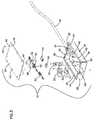
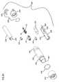
- FIG. 1is a perspective view of a hybrid fiber/copper cable assembly for connecting to a camera and including a junction box between a pair of cable connectors, with a optical fiber repair shown in dashed lines along one of the cable segments.
- FIG. 2is a perspective view of the junction box of FIG. 1 , with a first hybrid cable extending from one side of the junction box.
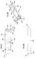
- FIG. 3is an exploded perspective view of the junction box of FIG. 2 , with fiber connectors shown for a second hybrid cable.
- FIG. 4is a schematic cross-section of a prior art hybrid fiber/copper cable including two optical fibers and four copper wires.
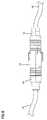
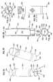
- FIG. 5is a perspective view of a pair of mating hybrid cable connectors of FIG. 1 .
- FIG. 6is a side view of the pair of mating hybrid cable connectors of FIG. 5 .
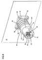
- FIG. 7is an exploded perspective view of the mating pair of connectors as shown in FIG. 5 .
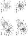
- FIG. 8is a perspective view of a camera bulkhead mount cable connector of FIG. 1 .
- FIG. 9is an exploded perspective view of the bulkhead mount cable connector of FIG. 8 .
- FIG. 10is an end view of the bulkhead mount cable connector of FIG. 8 .
- FIG. 11is a side view of a first mating cable connectors of FIG. 5 .
- FIG. 12is a perspective view of the mating cable connector of FIG. 11 .
- FIG. 13is an end view of the mating cable connector of FIG. 11 .
- FIG. 14is a perspective view of the second mating cable connector of FIG. 5 .
- FIG. 15is an end view of the cable connector of FIG. 14 .
- FIG. 16is an inner side view of a first housing half of the cable connector of FIG. 11 .
- FIG. 17is a first perspective view of the first housing half of FIG. 16 .
- FIG. 18is a second perspective view of the first housing half of FIG. 16 .
- FIG. 19is an inner side view of a second housing half of the cable connector of FIG. 11 .
- FIG. 20is a first perspective view of the second housing half of FIG. 16 .
- FIG. 21is a second perspective view of the second housing half of FIG. 16 .
- FIG. 22is an inner side view of a first housing half of the cable connector of FIG. 14 .
- FIG. 23is a first perspective view of the first housing half of FIG. 22 .
- FIG. 24is a second perspective view of the first housing half of FIG. 22 .
- FIG. 25is an inner side view of a second housing half of the cable connector of FIG. 14 .
- FIG. 26is a first perspective view of the second housing half of FIG. 25 .
- FIG. 27is a second perspective view of the second housing half of FIG. 25 .
- FIG. 28is a replacement fiber segment for use with the junction box and cable segments of FIG. 1 .
- FIG. 29is a perspective view of a pair of alternative embodiment mating hybrid fiber/copper cable connectors according to the present invention.
- FIG. 30is an exploded perspective view of one of the cable connectors of FIG. 29 .
- FIG. 31is an exploded perspective view of the other cable connector of FIG. 29 .
- FIG. 32is a perspective cross-sectional view of the mating pair of cable connectors of FIG. 29 .
- FIG. 33is a side cross-sectional of the mating pair of cable connectors of FIG. 29 .
- FIG. 34is a first perspective view of an outer housing for use with the connector of FIG. 30 .
- FIG. 35is a second perspective view of the outer housing of FIG. 34 .
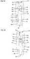
- FIG. 36is a side view of the outer housing of FIG. 34 .
- FIG. 37is a cable end view of the outer housing of FIG. 34 .
- FIG. 38is a mating end view of the outer housing of FIG. 34 .
- FIG. 39is a side cross-sectional view of the outer housing of FIG. 34 .
- FIG. 40is a perspective view of an outer housing for use with the connector of FIG. 31 .
- FIG. 41is a side view of the outer housing of FIG. 40 .
- FIG. 42is a cable end view of the outer housing of FIG. 40 .
- FIG. 43is a mating end view of the outer housing of FIG. 40 .
- FIG. 44is a side cross-sectional view of the outer housing of FIG. 40 .
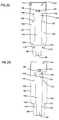
- FIG. 45is a perspective view of a first portion of a cable clamp for use with the cable connectors of FIGS. 29 to 31 .
- FIG. 46is a side view of the cable clamp portion of FIG. 45 .
- FIG. 47is a top cross-sectional view of the cable clamp portion of FIG. 45 .
- FIG. 48is a perspective view of a second portion of cable clamp for use with the cable connectors of FIG. 29 .
- FIG. 49is a first side view of the cable clamp portion of FIG. 48 .
- FIG. 50is an end view of the cable clamp portion of FIG. 48 .
- FIG. 51is a second side view of the cable clamp portion of FIG. 48 .
- FIG. 52is a top cross-sectional view of the cable clamp portion of FIG. 48 , taken along line 52 - 52 in FIG. 50 .
- FIG. 53is a perspective view of an inner housing half for use with the cable connector of FIG. 31 .
- FIG. 54is a top view of the inner housing half of FIG. 53 .
- FIG. 55is a side view of the inner housing half of FIG. 53 .
- FIG. 56is a perspective view of an inner housing half for use with the cable connector of FIG. 30 .
- FIG. 57is a top view of the inner housing half of FIG. 56 .
- FIG. 58is a side view of the inner housing half of FIG. 56 .
- FIG. 59is a perspective view of a fiber retainer for use with the connectors of FIGS. 30 and 31 .
- FIG. 60is a top view of the fiber retainer of FIG. 59 .
- FIG. 61is a side view of the fiber retainer of FIG. 59 .
- FIG. 62is a perspective of first electrical pin connector for use with the connectors of FIG. 30 .
- FIG. 63is an end view of the electrical pin connector of FIG. 62 .
- FIG. 64is a first side view of the electrical pin connector of FIG. 62 .
- FIG. 65is a second side view of the electrical connector of FIG. 62 .
- FIG. 66is a perspective of second electrical pin connector for use with the connectors of FIG. 31 .
- FIG. 67is an end view of the electrical pin connector of FIG. 66 .
- FIG. 68is a first side view of the electrical pin connector of FIG. 66 .
- FIG. 69is a second side view of the electrical connector of FIG. 66 .
- FIG. 70is a perspective view of a locking ring for use with the connector of FIG. 31 .
- FIG. 71is an end view of the locking ring of FIG. 70 .
- FIG. 72is a side view of the locking ring of FIG. 70 , with internal features shown in dashed lines.
- FIG. 73is a perspective view of a fiber connector retainer for use with the hybrid cable connector of FIG. 30 .
- FIG. 74is a side view of the fiber connector retainer of FIG. 73 .
- FIG. 75is an end view of the fiber connector retainer of FIG. 73 .
- FIG. 1illustrates a several segments of hybrid fiber and copper broadcast communications cable such as might be used to connect a camera to a production facility, such as at a sporting event or other entertainment venue.
- the segments of cable shown in FIG. 1include a first segment 10 extending from the production facility and terminated with a first cable connector 13 .
- Connector 13is mated with a second cable connector 11 which terminates a second cable segment 14 .
- Cable segment 14extends from one end of a junction box 16 and a third cable segment 18 extends from the other end.
- Cable segment 18is terminated with a third cable connector 19 (similar to first connector 13 ), which is configured to mate with a bulkhead mounted connector 20 positioned on a bulkhead 22 , which may form a portion of a camera.
- Second and third cable segments 14 and 18 , with second and third connectors 11 and 19 , along with junction box 16 ,may make up a camera connection assembly 24 that a camera operator would carry, such as on a belt mount, when operating a shoulder carried or other portable or mobile camera configuration.
- connectors 11 and 19in conjunction with junction box 16 , permit easier repair or replacement of damaged components of assembly 24 . Shown in dashed lines along segment 14 between junction box 16 and connector 11 is a replacement fiber 200 , which will be described in further detail below.
- junction box 16includes a first end 28 and a second end 30 .
- a cable entry fitting 32to permit cable segments 14 and 18 to enter junction box 16 .
- Fittings 32provide a seal about cable segments 14 and 18 to prevent entry of environmental contaminants into junction box 16 .
- Junction box 16also includes a housing 26 with a removable cover 34 permitting access to an interior of junction box 16 for repair or replacement of components within junction box 16 .
- housing 26 of junction box 16includes a main housing 36 which cooperates with cover 34 to define an interior 38 within which different components to connect fiber strands and copper conductors of cable segments 14 and 18 .
- Fittings 32may include a pair of identical halves 33 which fit closely about cable segments 14 and 18 . Other alternative configurations of fittings 32 are anticipated provided they permit extension of additional cables external to segments 14 or 18 from interior 38 .
- Cover 34may be removably held to main housing 36 by a plurality of removable fasteners such as screws 40 extending through openings 42 in cover 34 and engaging mating openings 44 in flanges 45 of main housing 36 .
- a pair of anchors 46for receiving and securing a linear strength member which extend within either of cable segments 14 and 18 .
- a bulkhead 48with a fiber optic adapter 50 mounted to it.
- Fiber optic adapter 50is configured to receive two fiber optic connectors 52 in each end.
- Known adapter 50is a standard fiber optic adapter to align and optically connect pairs of connectors 52
- known connectors 52may be mounted to the end of and terminate optical fibers extending within each of cable segments 14 and 18 .
- connector 52is a LX.5 format connector and adapter 50 is configured to receive and optically two connect LX.5 connectors.
- Other styles and types of fiber optic connectors and mating adaptersmay be used within junction box 16 .
- interior 38may be a pair of mating pin connectors 54 and 56 , which may terminate copper conductors extending within each of cable segments 14 and 18 , and also to electrically connect these copper conductors. Other types and styles of connectors for connecting copper conductors may also be used within junction box 16 .
- Interior 38may also include one or more cable routing features 58 to aid the positioning of optical fibers and copper conductors within junction box 16 .
- FIG. 4illustrates a schematic cross-section of a hybrid fiber/copper communications cable 100 , such as might be used for cable segments 10 , 14 and 18 .
- Cable 100includes an outer sheath 60 and may include a linearly extending central strength member 62 .
- Cable 100 as shownincludes a pair of jacketed optical fibers 64 and four jacketed copper conductors 66 , positioned within outer sheath 60 and extending adjacent strength member 62 .
- Other configurations of hybrid cablesare known, with more or fewer optical fibers and/or copper conductors.
- one of the optical fibers 64may be used to transmit video and related audio signals to the camera and the second optical fiber 64 may be used to transmit video and audio captured by the camera to the production facility or some other location.
- One pair of copper conductors 66may be used to provide power to operate the camera, while the other pair of copper conductors 66 may be used to provide communications between the production facility and the camera operator.
- the number of fiber strands and copper conductors extending within cable 100may be varied as required to support the desired usage and communication bandwidth of the camera.
- FIGS. 5 and 6show first cable segment 10 terminated by connector 11 , with connector 11 mated with connector 13 which terminates second cable segment 14 , as shown in FIG. 1 .
- Connectors 11 and 13cooperate to optically connect the fiber strands 64 of cable segment 10 with those of cable segment 14 , and to electrically connect copper conductors 66 of cable segment 10 with copper conductors 66 of cable segment 14 .
- These two connectorscooperate to form a secure and generally weather-tight cover 12 about the connections of the fiber strands and copper conductors.
- connector 11is defined as a male or plug connector and connector 13 is a female or socket connector.
- FIG. 7shows both connectors 11 and 13 including a pair of fiber optic connectors 52 which terminate fiber strands 64 within each cable segment 10 and 14 . These connectors are brought together, aligned and optically connected by adapter 50 mounted within connector 13 . Each copper conductor 66 may be terminated by a pin contact 68 and these pin contacts 68 may be mounted within mating pin connectors 54 and 56 , with pin connector 56 mounted within connector 11 and pin connector 54 mounted within connector 13 .
- Connector 11includes an outer housing defined by two housing portions 102 and 104 .
- Connector 13includes an outer housing defined by two housing portions 106 and 108 .
- bulkhead mounted connector 20includes an outer housing defined by two housing portions 110 and 112 .
- Housing portions 110 and 112define a central cavity 74 within which two connectors 52 and one pin connector 56 are mounted. Housing portions 110 and 112 also define an outer barrel portion 76 which is sized for insertion within a connector 13 .
- Barrel portion 76includes a pair of opposing tabs 70 to permit connector 13 to be releasable captured about barrel portion 76 , and an alignment feature 72 which engages a mating feature of connector 13 to properly orient connector 13 for mating with connector 20 .
- Each housing portion 110 and 112includes a mounting flange 78 .
- Openings 82are defined through flanges 78 for receiving removable fasteners such as screws 80 which engage fastener openings 84 of bulkhead 22 . Openings 84 are positioned about an opening 86 in bulkhead 22 which is sized to receive a rear portion 88 of connector 20 , opposite barrel portion 76 .
- Each housing portion 110 and 112includes a cable receiving end 90 of cavity 74 , adjacent rear portion 88 . Cables from within the camera or any other equipment, of which bulkhead 22 may form part of the case, enclosure or cabinet, enter into cavity 74 through cable receiving end 90 . Additional features of the structure of housing portions 110 and 112 within cavity 74 connector 20 are similar to features of housing portions 102 and 104 of connector 11 , shown in FIGS. 16 to 19 , below.
- connector 11includes the same exterior features as connector 20 , with the exception of the flanges 78 .
- Connector 11is intended for mounting to the end of a freestanding cable, so mounting flanges for mounting to a bulkhead 22 are not necessary.
- Connector 11does include an intermediate grip portion 92 to facilitate grasping connector 11 to break a seal 12 between connectors 11 and 13 .
- FIGS. 14 and 15show connector 13 including a barrel receiving end 77 within which barrel portion 76 of connector 11 or connector 20 may be received.
- Barrel receiving end 77defines an entry into a cavity 75 defined by the housing portions 106 and 108 .
- Adapter 50 and pin connector 54are mounted within cavity 75 .
- a pair of openings 96 through barrel receiving end 77are positioned to engage catches 98 of tabs 70 of connector 11 or 20 to releasably hold barrel portion 76 within connector 13 .
- a pair of tab release arms 71is positioned above openings 96 and each includes a tab release 94 .
- Tab release arms 71are inwardly deflectable, and when deflected inward, tab releases 94 extend through openings 96 to inwardly deflect tabs 70 from openings 96 so that barrel portion 76 may be removed from barrel receiving portion 77 .
- Inside barrel receiving portion 77 and cavity 75is an alignment feature 73 which cooperates with alignment feature 72 of barrel portion 76 to align connectors for mating.
- connector 13When properly aligned by alignment features 72 and 73 , connector 13 will mate with either connector 11 or 20 with the fiber connectors 52 aligned to extend into adapter 50 to optically connect fiber strands 64 and pin connectors 54 and 56 aligned to mate and electrically connect copper conductors 66 . As shown in FIG. 7 , within cavity 75 of connector 13 , a pair of fiber connectors 52 terminating fiber strands 64 of cable 14 segment are already positioned in an inner end of adapter 50 . When inserted into adapter 50 by mating of connectors 11 and 13 , fiber connectors 52 of connector 11 will be optically connected with fiber connectors 52 of connector 13 .
- housing portion 104 of connector 11includes a recess 126 which defines a portion of cavity 74 with a connector opening 127 and cable opening 90 on opposite ends.
- a strength member recess 114 and fastener opening 116for receiving a fastener to clamp strength member 62 of cable 100 .
- a pair of alignment pinsextend from an inner face 130 to aid in positioning of housing portions 102 and 104 for joining to form connector 11 .
- a plurality of fastener openings 120are formed in face for receiving fasteners to join housing portions 102 and 104 .
- Recess 126includes a longitudinal bulkhead 128 adjacent connector opening 127 which defines a pair of adjacent slots for receiving fiber connectors 52 .
- housing portion 102could be configured to include a cable clamp mounting arrangement, similar to housing portion 104 , described below.
- FIGS. 19 to 21show housing portion 102 including pin openings 122 positioned to cooperate with alignment pins 118 to align housing portions 102 and 104 . Openings 120 are positioned to receive fasteners extending through openings 120 of housing portion 104 . A recess 124 is positioned on an inner face 140 to permit a cable clamp to be positioned in recess 114 and opening 116 . Strength member 62 of cable 100 can be trimmed to fit within recess 114 and a cable clamp including a fastener such as a screw mounted within opening 116 to secure connector 11 to cable 100 . Alternatively, housing portion 102 could not include recess 114 and opening 116 if such an anchor is not required.
- a recess 132extends between cable entry 90 and a connector opening 134 on opposite ends.
- a plurality of fingers 136extend within recess 132 to organize copper conductors 66 extending from cable 100 to pin connector 56 .
- a pin connector mounting area 138is defined on the connector opening side of pins 136 .
- recesses 126 and 132When mounted together as shown in FIGS. 12 and 13 , recesses 126 and 132 cooperate to form cavity 74 within connector 11 .
- FIGS. 22 to 24show housing portion 108 of connector 13 including a recess 142 extending from a connector receiving opening 144 to cable entry 90 on opposite ends.
- an adapter receiving area 146adjacent connector receiving opening 144 .
- Adapter receiving area 146is sized to closely fit about adapter 50 and includes a flange recess 148 on either side to engage a flange of adapter 50 to secure adapter 50 in the desired position within recess 142 .
- Housing portion 108also includes a pair of alignment pins 118 and a plurality of fastener openings 120 in an inner face 150 .
- housing portion 108could be configured to include a cable clamp mounting arrangement, similar to recess 114 and opening 116 of housing portion 104 , above.
- FIGS. 25 to 27show housing portion 106 of connector 13 including a recess 152 extending from connector receiving end 144 to cable entry 90 .
- recess 152Within recess 152 are a plurality of fingers 154 and a pin connector mounting area is defined between fingers 154 and connector receiving end 144 .
- Fingers 154organize and direct copper conductors 66 of cable 100 and serve to correctly position pin connector 54 within connector 13 so that pin connector 54 engages pin connector 56 of mating connector 11 .
- An inner face 160 of housing portion 106includes a plurality of fastener openings 120 for receiving fasteners extending through openings 120 of housing portion 108 to hold the two housing portions together to form an outer housing of connector 13 .
- housing portion 106could be configured to include a cable clamp mounting arrangement, similar to recess 114 and opening 116 of housing portion 104 , above.
- recesses 142 and 152When mounted together as shown in FIGS. 14 and 15 , recesses 142 and 152 cooperate to form cavity 75 within connector 13 .
- both connectors 11 and 13be constructed with outer housings having two or more portions which are removable to expose the interior cavity of the connectors. It is also preferable that cable entry 90 of connectors 11 and 13 , as well as cable fittings 32 of junction box 16 be sized slightly larger than the diameter of outer sheath 60 of cable 100 . It is known for one or more elements 64 and 66 within cable 100 in segments 14 or 18 or the connectors terminating these elements (such as fiber connectors 52 and pin connectors 54 and 56 ) to be damaged, necessitating repair or replacement of assembly 24 . While replacement is possible and is the common response to damage, this solution requires a camera operator to carry an entire spare assembly 24 .
- Assembly 24is constructed to permit individual elements 64 or 66 of cable 100 or terminations 52 , 54 or 56 of these elements to be quickly replaced in the field by a camera operator with simple tools and does not require that the camera operator carry an extensive array of replacement items.
- the camera operatormay open junction box 16 by removing cover 34 from main housing 28 . With interior 38 exposed, the fiber connector 52 terminating the damaged fiber may be removed from adapter 50 within junction box 16 and moved to one side.
- Replacement fiber segment 200may include ends terminated with connectors 52 . One of these connectors 52 may be inserted within adapter 50 in place of connector 52 of damaged fiber 64 .
- the top half 33 of cable fitting 32is removed from about cable 100 and a cable length 202 between connectors 52 of replacement fiber 200 extended out of junction box 16 along cable segment 18 .
- cable length 202 of replacement fiber segment 200includes a jacketed fiber optic cable such as a standard 2 to 3 millimeter fiber cable.
- this cable length 202is intended primarily as a temporary field repair, and will be extended along and supported by one of the cable segments 14 or 18 , additional reinforcing structure other than typical jacketing should not be required.
- more heavily protected cable jackets and other reinforcing structures within cable length 202may be used as convenient or desirable, based on the conditions to which assembly 24 may be subject to or based on the repair materials that may readily available to the camera operator.
- Replacement fiber segment 200is extended along cable segment 18 to connector 13 .
- Connector 13is removed from bulkhead connector 20 and fasteners holding housing portions 106 and 108 together are removed. Housing portions 106 and 108 are separated from each other permitting access into recess 142 of housing portion 108 .
- fiber connector 52 terminating the damaged fiber strand 64is removed from adapter 50 .
- This fiber connector 52is removed from recess 142 to provide room for connector 52 terminating an end of replacement fiber 200 .
- This connector 52 of replacement fiber 200is inserted within adapter 50 in place of the removed damaged connector 52 of cable segment 18 .
- Cable length 202is extended from adapter 50 within recess 142 out of cable entry 90 and housing portions 106 and 108 are refastened together.
- the damaged fiber strand 64 of cable 100 of cable segment 18has been replaced with replacement fiber 200 and the camera operator can continue operating the camera.
- a similar processis followed to replace a damaged copper conductor or damaged pin connector.
- the replacement fiber or copperis extended out of junction box 16 and cavity 74 along cable segment 18 .
- This replacement fiberis copper may be attached to cable segment 18 to provide support or additional protection to the replacement.
- each connector 300 and 302includes a cable receiving end 304 with a cable clamp 306 through which one of the cable segments might extend.
- Connector 300has a mating end 308 opposite cable receiving end 304 which defines a female or socket connector end.
- Connector 302has a mating end 310 opposite cable receiving end 304 which defines a male or plug connector end configured to mate with end 308 of connector 300 .
- a locking ring 312is rotatably mounted about cable mating end 308 , 310 to releasably lock the two connectors to each other (as shown below in FIGS. 32 and 33 ).
- An outer housing 314includes an interior 320 within which is positioned a pair of inner housing halves 316 .
- Inner housing halves 316cooperate to define an inner housing within an interior 318 .
- Within interior 318are positioned a pair of fiber optic connectors 52 , which may terminate ends of optical fiber within cable 11 or cable 13 .
- a connector retainer 324cooperates with bulkheads within interior 318 to position and hold fiber connectors 52 adjacent mating end 308 .
- Positioned on opposite sides of fiber connectors 52is a pair of electrical pin jack housings 322 .
- Pin jack housings 322are also accessible through mating end 308 and may provide a termination for electrical conductors within cable 11 or cable 13 .
- a cable retainer 324cooperates with a cable management structures 326 within interior 318 to provide cable management and cable slack storage for either fibers or electrical conductors extending through cable receiving end 304 .
- cable clampmounts about an end 334 of outer housing 314 and includes a first portion 328 and a second portion 330 .
- a pair of o-rings or similar items 332may also be included in connector 300 to provide improved seals between the various components.
- connector 302includes an inner housing 336 defining an interior 340 within which may be positioned a pair of inner housing halves 338 . Housing halves 338 cooperate to define an inner housing with an interior 342 . Positioned within interior 342 are a fiber optic adapter 50 and a pair of fiber optic connectors 52 , which may terminate ends of optical fiber within cable 11 or cable 13 . As is well known in the telecommunications industry, connectors 52 may be inserted within opposite ends adapter 50 to optically connect fibers terminated within connectors 52 . Positioned on opposite sides of fiber adapter 50 is a pair of electrical pin jack housings 344 .
- Pin jacks 344are also accessible through mating end 308 and may provide a termination for electrical conductors within cable 14 or cable 18 .
- Pin jack housings 322 and 344are configured to mate with each other and electrically connect electrical conductors terminated within pin jack housings 322 and 344 .
- Interior 342also includes cable management structures 326 and cable retainer 324 to aid the management and storage of cables within interior 342 .
- Cable clamp 306is mounted to end 334 of outer housing 336 .
- Locking ring 312may mounted to an opposite end of outer housing 336 by cooperation of a washer 346 received rotatably within a recess 348 .
- FIGS. 32 and 33show connectors 300 and 302 mated together at mating ends 308 and 310 , respectively.
- Fiber connectors 52 of connector 300are received within adapter 50 and optically mated with fiber connectors 52 of connector 302 .
- Pin jack housings 322 of connector 300position pins 68 of wires 66 so that they are mated with and electrically connected to pins 68 and wires 66 held within pin jack housings 344 of connector 302 .
- Locking ring 312has been rotated and advanced along an outer surface of mating end 308 and engaged features on that outer surface to hold connector 300 to connector 302 .
- a hybrid fiber/copper cablesuch as cable segment 14 or 18 , would extend into either of interior 318 or 342 through an opening 350 in cable receiving end 304 .
- Fibers 64 and electrical conductors or wires 66are separated from within the hybrid cable 10 and extend from cable receiving end 304 toward mating ends 308 and 310 . If necessary, any or all of fibers 64 or wires 66 may be directed about cable management structures 326 before reaching a termination at either fiber connector 52 or pin jack housings 322 or 344 .
- an elementsuch as the fiber segment 200 described above, is the same length as cable segment 14 , there is no need to direct the replacement fiber 200 about cable management structures 326 to store excess slack.
- cable segment 14may have been previously reterminated and now is a shorter length than originally contemplated when replacement fiber segment 200 was produced.
- cable management structures 326 and cable retainer 324may be used to store excess slack so that replacement segment 200 may be closely matched in length to cable segment 14 .
- Cable management structures 326may also be used when terminating any of the various hybrid cable segments shown in FIG. 1 . In circumstances when the fibers 64 or wires 66 extending from the cable segment for termination are of different lengths, cable management structures 326 may be used to provide storage of the excess length of the longer elements so that all elements are an appropriate length. This will ensure that all terminations are correctly positioned within the connector 300 or 302 and that no undesirable bending or kinking of the elements occurs within interior 318 or 342 , respectively.
- FIGS. 34 to 39show outer housing 314 of connector 300 with a second end 352 opposite cable clamp end 334 .
- Second end 352defines a portion of mating end 308 and includes at least one pin 362 extending from an outer surface and at least one key slot 364 on an inner wall 360 of interior 320 .
- Pins 362provide a locking engagement with locking ring 312 of connector 302 .
- Key slots 364aid in orientation of the two connectors 300 and 302 for proper engagement of fiber connectors 52 with adapter 50 and pin jacks 322 with pin jacks 344 .
- a central portion 354 of outer housing 314may be knurled or otherwise provided with a slip resistant surface to aid in handling of connector 300 .
- Adjacent cable clamp end 334is a wrench flat portion 356 with a plurality of opposing wrench flats to aid the assembly of cable clamp 306 to outer housing 314 and connector 300 . As shown on FIG. 36 , cable clamp end 334 may be threaded to receive and engage cable clamp portion 328 . Within interior 320 on inner wall 360 adjacent cable clamp end 334 are one or more recesses 366 which engage a tab of one of the inner housing halves 338 to orient the inner and outer housings with respect to each other and to prevent rotation of the inner and outer housings with respect to each other. Formed in inner wall 360 within interior 320 is an o-ring groove 368 for receiving o-ring 332 .
- FIGS. 40 to 44show outer housing 336 of connector 302 with a second end 370 opposite clamp end 334 .
- Second end 370defines a portion of mating end 310 and includes a plurality of keys 372 extending from an outer surface. Keys 372 are arranged to cooperate with key slots 364 of outer housing 314 to uniquely orient connectors 300 and 302 for proper mating of mating ends 308 and 310 .
- Interior 340includes an inner wall 374 in which are formed recesses 366 adjacent cable clamp end 334 .
- Cable clamp end 334includes wrench flat portion 356 with wrench flats 358 .
- Recess 348is formed between central portion 354 and second end 370 to receive washer 346 .
- first portion 328 of cable clamp 306includes a ring portion 376 that extends continuously about cable receiving opening 350 .
- ring portion 376On an inner wall 378 within ring portion 376 are threads for engaging cable clamp end 334 of housings 314 and 336 .
- wrench flats 358Formed on an exterior surface of first portion 328 are wrench flats 358 to aid in assembly of connectors 300 and 302 .
- Opposite ring portion 376is an outer end 380 with a relieved section 382 so that outer end 380 is not generally continuous about opening 350 .
- Relieved section 382receives second portion 330 to clamp about a hybrid cable such as cable 14 or 18 .
- a pair of fastener openings 384are included within relieved section 382 to receive fasteners mounting second portion 330 to first portion 328 and tightly about the cable extending through opening 350 .
- a circumferential recess 388Positioned within opening 350 and at least partially within relieved section 382 , is a circumferential recess 388 for receiving a collar or other similar device which fits about the cable within opening 350 . The collar will permit variations in an outer diameter of the cable to be accounted for to ensure that cable clamp 306 engages the cable tightly.
- an o-ring recess 386for receiving an o-ring when connector 302 is assembled.
- FIGS. 48 to 52illustrate second portion 330 of cable clamp 306 which fits within relieved section 382 of first portion 328 .
- Second portion 330also forms part of opening 350 and cooperates with first portion 328 to completely define cable receiving opening 350 into interior 318 or 340 .
- a recess 390 on an inner wall of second portion 330cooperates with recess 388 to define a generally continuous collar receiving recess for a cable collar positioned about cable 14 or 18 .
- On an exterior surface 396is a pair of fastener recesses 392 and fastener openings 394 . Fasteners such as screws or other removable fasteners may extend through opening 394 and engage openings 384 of first portion 328 to engage a cable within opening 350 .
- Recesses 392provide a uniform and generally perpendicular surface for the fasteners to engage.
- inner housing half 338 of connector 302includes an outer surface 398 , a first end 400 which is positioned adjacent mating end 310 of connector 302 and a second end 402 positioned adjacent cable clamp end 334 of connector 302 .
- a tab 404engages recess 366 within interior 340 of outer housing 336 .
- a loop 365 of fiber 64may extend about one or both of cable management structures 326 within interior 342 to provide slack storage of excess cable length and to provide bend radius protection to cable within loop 365 .
- Adjacent first end 400is a slot 406 sized and configured to engage a mounting flange of adapter 50 so that adapter 50 may be securely held within interior 318 of connector 302 .
- a pair of bulkheads 408define slot 406 and define an opening in first end 400 to permit adapter 50 to extend from interior 342 at mating end 310 .
- Bulkheads 408also define an opening 410 for pin jack housings 344 to extend through from interior 342 toward mating end 310 .
- Slot 406also extends through pin jack opening 410 and engages a mounting flange of pin jack housings 344 .
- Outer surface 398is closely engaged by inner wall 374 of interior 340 of outer housing 336 . The close engagement of outer surface 398 and inner wall 374 ensures that adapter 50 and pin jack housings 344 are held securely in the desired locations within interior 342 so that they can be aligned with and engage mating features of connector 300 .
- inner housing half 316 of connector 300includes a first end 412 which is positioned adjacent mating end 308 of connector 300 and a second end 414 which is positioned adjacent cable clamp end 334 of connector 300 .
- Housing halfalso includes outer surface 398 and alignment tab 404 adjacent second end 414 .
- a slot 416is defined by a pair of bulkheads 418 .
- Slot 416is sized and configured to receive connector retainer 323 that fits about fiber connectors 52 .
- Connector retainer 323positions and holds connectors within mating end 308 .
- An additional interior bulkhead 420provides a stop engaging an inner edge of fiber connectors 52 and holding connectors 52 in position to engage and mate within adapter 50 of connector 302 .
- Bulkheads 418 and 420also define an opening 422 to permit pin jack housing 322 to extend from interior 318 toward mating end 308 .
- Slot 416extends through opening 422 to engage a mounting flange of pin jack housing 322 .
- Cable management structures 326 within interior 318include openings 325 to receive a pin of cable retainer 324 between two inner housing halves 316 , as shown in FIGS. 32 and 33 .
- Cable retainer 324is shown in FIGS. 59 to 61 and includes a central plate 424 ad a pair of pins 426 extending on both sides of plate 424 .
- Pins 426are received within openings 325 of cable management structures 326 to position and hold cable retainer within interior 318 or 342 .
- Pins 424may be of different lengths, as shown, which may assist in the assembly of connectors 300 and 302 , or may generally the same length.
- plate 424When assembled as shown in FIGS. 32 and 33 , plate 424 will block off a portion of interior 318 of each inner housing half 316 (or interior 342 of each inner housing half 336 ) to retain fiber or wires about cable management structures 326 .
- FIGS. 62 to 65illustrate male pin jack housing 322 with a mounting tab 428 which engages slot 416 within inner housing half 316 .
- a plurality of pin supports 430extend from one end of a body 432 and provide support for pins 68 terminating wires 66 .
- At an opposite end of body 432are channels 434 for receiving wires 66 .
- Pin supports 430are received within mating support recesses 436 in an end 438 of a body 440 of female pin jack housing 344 , shown in FIGS. 66 to 69 .
- Pin jack housing 344includes mounting tab 428 to be received within slot 406 of inner housing half 338 .
- channels 442for receiving wires 66 .
- locking ring 312includes an exterior surface 454 which may be knurled or otherwise textured to provide secure grip.
- an inner wall 446are a plurality of angled channels 444 for receiving and engaging pins 362 of connector 300 to releasably hold connectors 300 and 302 together.
- an end 448 of locking ring 312extends over second end 352 until each pin 362 is positioned within a channel 444 .
- Locking ring 312is then rotated to draw pins 362 deeper within channels 444 until pins 362 are received within a pin channel 445 .
- Washer 346is received within a groove 452 in inner wall 446 adjacent an opposite end 450 of locking ring 312 .
- the engagement of washer 346 by both groove 452 and recess 348permit some longitudinal movement of locking ring 312 along connector 302 while securing locking ring 312 to connector 302 .
- Connector retainer 323is shown in FIGS. 73 to 75 , and includes a pair of side extensions 454 which extend to engage slots 416 of inner housing halves 316 .
- a top 456 and a bottom 457may rest against pin jack housings 322 within connector 300 to ensure that mounting tabs 428 remain engaged with slot 416 .
- adapter 50may rest against pin jack housing 344 to ensure that mounting tabs 428 remain engaged with slots 406 .
- a pair of openings 458extends through retainer 323 and are sized and configured to receive fiber connectors 52 .
- a portion 460 of openings 458is provided to engage a locking or retention mechanism of connector 52 . While opening 458 and portion 460 are shown to engage one format of fiber optic connector, openings 458 may be modified as needed to fit the fiber optic connector used.
Landscapes
- Physics & Mathematics (AREA)
- General Physics & Mathematics (AREA)
- Optics & Photonics (AREA)
- Connector Housings Or Holding Contact Members (AREA)
- Mechanical Coupling Of Light Guides (AREA)
- Multi-Conductor Connections (AREA)
Abstract
Description
Claims (20)
Priority Applications (1)
| Application Number | Priority Date | Filing Date | Title |
|---|---|---|---|
| US12/156,946US7798725B2 (en) | 2005-04-15 | 2008-06-04 | Hybrid fiber/copper connector system and method |
Applications Claiming Priority (2)
| Application Number | Priority Date | Filing Date | Title |
|---|---|---|---|
| US11/107,414US7393144B2 (en) | 2005-04-15 | 2005-04-15 | Hybrid fiber/copper connector system and method |
| US12/156,946US7798725B2 (en) | 2005-04-15 | 2008-06-04 | Hybrid fiber/copper connector system and method |
Related Parent Applications (1)
| Application Number | Title | Priority Date | Filing Date |
|---|---|---|---|
| US11/107,414ContinuationUS7393144B2 (en) | 2005-04-15 | 2005-04-15 | Hybrid fiber/copper connector system and method |
Publications (2)
| Publication Number | Publication Date |
|---|---|
| US20090180739A1 US20090180739A1 (en) | 2009-07-16 |
| US7798725B2true US7798725B2 (en) | 2010-09-21 |
Family
ID=36716923
Family Applications (2)
| Application Number | Title | Priority Date | Filing Date |
|---|---|---|---|
| US11/107,414Expired - Fee RelatedUS7393144B2 (en) | 2005-04-15 | 2005-04-15 | Hybrid fiber/copper connector system and method |
| US12/156,946Expired - LifetimeUS7798725B2 (en) | 2005-04-15 | 2008-06-04 | Hybrid fiber/copper connector system and method |
Family Applications Before (1)
| Application Number | Title | Priority Date | Filing Date |
|---|---|---|---|
| US11/107,414Expired - Fee RelatedUS7393144B2 (en) | 2005-04-15 | 2005-04-15 | Hybrid fiber/copper connector system and method |
Country Status (7)
| Country | Link |
|---|---|
| US (2) | US7393144B2 (en) |
| EP (1) | EP1875286A1 (en) |
| JP (1) | JP4819877B2 (en) |
| CN (1) | CN101160541B (en) |
| AR (1) | AR053057A1 (en) |
| TW (1) | TW200643497A (en) |
| WO (1) | WO2006113154A1 (en) |
Cited By (3)
| Publication number | Priority date | Publication date | Assignee | Title |
|---|---|---|---|---|
| US20100172648A1 (en)* | 2005-08-24 | 2010-07-08 | Philip Longhurst | Installation for Conveying a First Plurality of Electrical Signals Carried by a First Triaxial Cable to a Second Triaxial Cable |
| US20110200286A1 (en)* | 2010-02-04 | 2011-08-18 | Adc Telecommunications, Inc. | Ruggedized Fiber Optic/Electrical Connection System |
| US12009117B2 (en) | 2022-05-16 | 2024-06-11 | Panduit Corp. | Hybrid fiber optic and electrical connector |
Families Citing this family (29)
| Publication number | Priority date | Publication date | Assignee | Title |
|---|---|---|---|---|
| US7393144B2 (en)* | 2005-04-15 | 2008-07-01 | Adc Telecommunications, Inc. | Hybrid fiber/copper connector system and method |
| JP3987078B2 (en)* | 2005-08-31 | 2007-10-03 | 日本電信電話株式会社 | Optical connector |
| US20070116414A1 (en)* | 2005-11-18 | 2007-05-24 | Applied Optical Systems, Inc | Versatile system for configurable hybrid fiber-optic/electrical connectors |
| US7481585B2 (en)* | 2006-11-29 | 2009-01-27 | Adc Telecommunications, Inc. | Hybrid fiber/copper connector system and method |
| US7490994B2 (en)* | 2006-11-29 | 2009-02-17 | Adc Telecommunications, Inc. | Hybrid fiber/copper connector system and method |
| WO2008067456A2 (en)* | 2006-11-29 | 2008-06-05 | Adc Telecommunications, Inc. | Fiber connector system and method |
| US7744287B2 (en)* | 2007-09-05 | 2010-06-29 | Adc Telecommunications, Inc. | Connector enclosure |
| US8083416B2 (en)* | 2007-11-30 | 2011-12-27 | Adc Telecommunications, Inc. | Hybrid fiber/copper connector system and method |
| US8333519B2 (en)* | 2008-08-29 | 2012-12-18 | Adc Telecommunications, Inc. | Splice of fiber optic cables |
| US8640329B2 (en)* | 2008-09-03 | 2014-02-04 | Adc Telecommunications, Inc. | Hybrid fiber/copper cable preparation tool |
| CA2746868C (en)* | 2009-01-26 | 2016-05-17 | Afl Telecommunications Llc | High conductor count packaging capsule |
| US7736159B1 (en) | 2009-04-07 | 2010-06-15 | Tyco Electronics Corporation | Pluggable connector with differential pairs |
| WO2010124733A1 (en)* | 2009-04-29 | 2010-11-04 | Abb Technology Ag | Repair box for optical fibre composite electric power cable |
| US8241068B2 (en) | 2010-08-30 | 2012-08-14 | Tyco Electronics Corporation | Pluggable connector with differential pairs having an air core |
| US8460024B2 (en) | 2011-03-14 | 2013-06-11 | Tyco Electronics Corporation | Contact assembly for electrical connector |
| US8764487B2 (en) | 2011-05-05 | 2014-07-01 | Precision Concepts Group Llc | Connector assembly, device, and kit |
| US9147950B2 (en) | 2011-05-25 | 2015-09-29 | Precision Concepts Group Llc | Connector assembly and device and methods of assembling same |
| US9819107B2 (en)* | 2013-11-26 | 2017-11-14 | Glenair, Inc. | Advanced panel mount connector and method |
| US9497525B2 (en) | 2014-09-12 | 2016-11-15 | Corning Optical Communications LLC | Optical engines and optical cable assemblies having electrical signal conditioning |
| CA2971584C (en)* | 2014-12-19 | 2023-08-01 | 3M Innovative Properties Company | Ruggedized optical fiber connection structures and assemblies |
| US10113669B2 (en) | 2016-01-15 | 2018-10-30 | The Boeing Company | Pass-through bulkhead seal fitting |
| DE102018110867B4 (en)* | 2018-05-07 | 2020-03-12 | Amphenol Tuchel Industrial GmbH | Rectangular connector for contact carriers |
| US11652337B2 (en)* | 2019-05-10 | 2023-05-16 | Meta Platforms, Inc. | Systems and methods for installing fiber optic cable onto a powerline conductor |
| US10826247B1 (en)* | 2019-06-05 | 2020-11-03 | The Boeing Company | Electromagnetic shielding systems and methods for aircraft |
| US11353672B1 (en) | 2019-11-27 | 2022-06-07 | Meta Platforms, Inc. | Components for fiber optic cable installation on a powerline conductor |
| CN113629649B (en)* | 2021-08-06 | 2023-06-27 | 中天科技海缆股份有限公司 | Floating photovoltaic power station |
| TWI820765B (en)* | 2021-08-16 | 2023-11-01 | 顏玉惠 | Connector shroud |
| CN115826150B (en)* | 2022-11-29 | 2025-02-14 | 四川天邑康和通信股份有限公司 | Photoelectric hybrid jumper, photoelectric hybrid adapter and assembly method |
| WO2024137176A1 (en)* | 2022-12-21 | 2024-06-27 | Commscope Technologies Llc | Adapters for a connection interface and related connection interface assemblies |
Citations (27)
| Publication number | Priority date | Publication date | Assignee | Title |
|---|---|---|---|---|
| US4373777A (en) | 1980-08-11 | 1983-02-15 | International Telephone And Telegraph Corporation | Connector and cable assembly |
| GB2154333A (en) | 1984-01-25 | 1985-09-04 | Int Standard Electric Corp | Connector coupling for optical waveguides |
| US4568145A (en) | 1981-08-26 | 1986-02-04 | Les Cables De Lyon | Connection device for a cable incorporating optical fibers and metal conductors |
| EP0204581A2 (en) | 1985-06-07 | 1986-12-10 | Telephone Cables Limited | Splice storage housing |
| US4728171A (en) | 1986-10-20 | 1988-03-01 | Amphenol Corporation | System for use in temporary repair of multiple fiber cable |
| US5109452A (en) | 1990-07-16 | 1992-04-28 | Puritan-Bennett Corporation | Electrical-optical hybrid connector |
| US5242315A (en) | 1992-05-21 | 1993-09-07 | Puritan-Bennett Corporation | Electrical-optical hybrid connector plug |
| US5745622A (en) | 1995-09-08 | 1998-04-28 | Siemens Aktiengesellschaft | Hybrid plug-type connector with modular electrical and light waveguide connections |
| US5982971A (en) | 1996-10-10 | 1999-11-09 | Tyco Submarine Systems Ltd. | Floating fiber storage assembly |
| US6115159A (en) | 1997-03-27 | 2000-09-05 | Telecast Fiber Systems, Inc. | Apparatus for fiber optic triaxial camera interface |
| US6234683B1 (en) | 1999-09-13 | 2001-05-22 | Stratos Lightwave, Inc. | Field repairable hermaphroditic connector |
| US6254278B1 (en) | 1999-10-06 | 2001-07-03 | Lucent Technologies Inc. | Optical fiber tunable connector adapter |
| US6357931B1 (en) | 1999-11-19 | 2002-03-19 | Yazaki Corporation | Hybrid connector |
| US6475009B2 (en) | 2000-06-02 | 2002-11-05 | The Siemon Company | Industrial telecommunications connector |
| US6478625B2 (en) | 2000-07-11 | 2002-11-12 | Bernard R. Tolmie | Electrical-optical hybrid connector |
| DE20202835U1 (en) | 2002-02-22 | 2003-03-27 | CCS Technology, Inc., Wilmington, Del. | Optical cable jack-plug connector has connector plugs at ends of optical cables inserted in opposing ends of socket sleeve providing both electrical and optical conductor connections |
| US6579014B2 (en) | 2001-09-28 | 2003-06-17 | Corning Cable Systems Llc | Fiber optic receptacle |
| US6612857B2 (en) | 2001-07-05 | 2003-09-02 | Bernard R. Tolmie | Electrical connector system and method having optical and/or cooling capability |
| US6648520B2 (en) | 2001-09-28 | 2003-11-18 | Corning Cable Systems Llc | Fiber optic plug |
| US6719461B2 (en) | 2002-02-19 | 2004-04-13 | Fiber Systems International | Hybrid fiber optic and power connector |
| US6733185B2 (en) | 2002-08-12 | 2004-05-11 | Hon Hai Precision Ind. Co., Ltd. | Optical fiber connector assembly having fiber saver |
| US6739759B1 (en) | 2003-03-13 | 2004-05-25 | Itt Manufacturing Enterprises, Inc. | Protected optical interface |
| US6856748B1 (en) | 2003-09-30 | 2005-02-15 | Corning Cable Systems Llc | Interconnection enclosure having a connector port and preterminated optical connector |
| US6962445B2 (en) | 2003-09-08 | 2005-11-08 | Adc Telecommunications, Inc. | Ruggedized fiber optic connection |
| WO2006039084A1 (en) | 2004-09-10 | 2006-04-13 | Adc Telecommunications, Inc. | Hybrid fiber/copper connector system and method |
| US7111990B2 (en) | 2000-05-26 | 2006-09-26 | Corning Cable Systems, Llc | Figure-eight preconnectorized fiber optic drop cables and assemblies |
| US7393144B2 (en)* | 2005-04-15 | 2008-07-01 | Adc Telecommunications, Inc. | Hybrid fiber/copper connector system and method |
Family Cites Families (9)
| Publication number | Priority date | Publication date | Assignee | Title |
|---|---|---|---|---|
| US4496213A (en)* | 1982-10-29 | 1985-01-29 | International Telephone And Telegraph Corporation | Audible indicator for a connector |
| JPH03107377A (en)* | 1989-09-20 | 1991-05-07 | Juki Corp | inverter |
| JP2548961Y2 (en)* | 1991-03-28 | 1997-09-24 | 矢崎総業株式会社 | Self-aligning connector |
| JPH0668943A (en)* | 1992-08-19 | 1994-03-11 | Fuji Facom Corp | Connector for communication |
| JP2001166182A (en)* | 1999-12-08 | 2001-06-22 | Yazaki Corp | Optical connector assembling method, optical connector, and hybrid connector |
| JP3921571B2 (en)* | 2001-11-21 | 2007-05-30 | モレックス インコーポレーテッド | Composite connector device |
| JP2003157926A (en)* | 2001-11-22 | 2003-05-30 | Sanwa Denki Kogyo Co Ltd | Optical and electric compound connector device |
| JP2004039258A (en)* | 2002-06-28 | 2004-02-05 | Fujikura Ltd | Photoelectric hybrid connector |
| US6802746B2 (en)* | 2002-12-11 | 2004-10-12 | Molex Incorporated | Electrical connector with terminal position assurance system |
- 2005
- 2005-04-15USUS11/107,414patent/US7393144B2/ennot_activeExpired - Fee Related
- 2006
- 2006-04-07JPJP2008506528Apatent/JP4819877B2/ennot_activeExpired - Fee Related
- 2006-04-07WOPCT/US2006/012890patent/WO2006113154A1/enactiveApplication Filing
- 2006-04-07EPEP20060749442patent/EP1875286A1/ennot_activeWithdrawn
- 2006-04-07CNCN2006800126003Apatent/CN101160541B/ennot_activeExpired - Fee Related
- 2006-04-14TWTW095113562Apatent/TW200643497A/enunknown
- 2006-04-17ARARP060101495patent/AR053057A1/enactiveIP Right Grant
- 2008
- 2008-06-04USUS12/156,946patent/US7798725B2/ennot_activeExpired - Lifetime
Patent Citations (28)
| Publication number | Priority date | Publication date | Assignee | Title |
|---|---|---|---|---|
| US4373777A (en) | 1980-08-11 | 1983-02-15 | International Telephone And Telegraph Corporation | Connector and cable assembly |
| US4568145A (en) | 1981-08-26 | 1986-02-04 | Les Cables De Lyon | Connection device for a cable incorporating optical fibers and metal conductors |
| GB2154333A (en) | 1984-01-25 | 1985-09-04 | Int Standard Electric Corp | Connector coupling for optical waveguides |
| EP0204581A2 (en) | 1985-06-07 | 1986-12-10 | Telephone Cables Limited | Splice storage housing |
| US4728171A (en) | 1986-10-20 | 1988-03-01 | Amphenol Corporation | System for use in temporary repair of multiple fiber cable |
| US5109452A (en) | 1990-07-16 | 1992-04-28 | Puritan-Bennett Corporation | Electrical-optical hybrid connector |
| US5242315A (en) | 1992-05-21 | 1993-09-07 | Puritan-Bennett Corporation | Electrical-optical hybrid connector plug |
| US5745622A (en) | 1995-09-08 | 1998-04-28 | Siemens Aktiengesellschaft | Hybrid plug-type connector with modular electrical and light waveguide connections |
| US5982971A (en) | 1996-10-10 | 1999-11-09 | Tyco Submarine Systems Ltd. | Floating fiber storage assembly |
| US6115159A (en) | 1997-03-27 | 2000-09-05 | Telecast Fiber Systems, Inc. | Apparatus for fiber optic triaxial camera interface |
| US6234683B1 (en) | 1999-09-13 | 2001-05-22 | Stratos Lightwave, Inc. | Field repairable hermaphroditic connector |
| US6254278B1 (en) | 1999-10-06 | 2001-07-03 | Lucent Technologies Inc. | Optical fiber tunable connector adapter |
| US6357931B1 (en) | 1999-11-19 | 2002-03-19 | Yazaki Corporation | Hybrid connector |
| US7111990B2 (en) | 2000-05-26 | 2006-09-26 | Corning Cable Systems, Llc | Figure-eight preconnectorized fiber optic drop cables and assemblies |
| US6475009B2 (en) | 2000-06-02 | 2002-11-05 | The Siemon Company | Industrial telecommunications connector |
| US6478625B2 (en) | 2000-07-11 | 2002-11-12 | Bernard R. Tolmie | Electrical-optical hybrid connector |
| US6612857B2 (en) | 2001-07-05 | 2003-09-02 | Bernard R. Tolmie | Electrical connector system and method having optical and/or cooling capability |
| US6579014B2 (en) | 2001-09-28 | 2003-06-17 | Corning Cable Systems Llc | Fiber optic receptacle |
| US6648520B2 (en) | 2001-09-28 | 2003-11-18 | Corning Cable Systems Llc | Fiber optic plug |
| US6719461B2 (en) | 2002-02-19 | 2004-04-13 | Fiber Systems International | Hybrid fiber optic and power connector |
| DE20202835U1 (en) | 2002-02-22 | 2003-03-27 | CCS Technology, Inc., Wilmington, Del. | Optical cable jack-plug connector has connector plugs at ends of optical cables inserted in opposing ends of socket sleeve providing both electrical and optical conductor connections |
| US6733185B2 (en) | 2002-08-12 | 2004-05-11 | Hon Hai Precision Ind. Co., Ltd. | Optical fiber connector assembly having fiber saver |
| US6739759B1 (en) | 2003-03-13 | 2004-05-25 | Itt Manufacturing Enterprises, Inc. | Protected optical interface |
| US6962445B2 (en) | 2003-09-08 | 2005-11-08 | Adc Telecommunications, Inc. | Ruggedized fiber optic connection |
| US6856748B1 (en) | 2003-09-30 | 2005-02-15 | Corning Cable Systems Llc | Interconnection enclosure having a connector port and preterminated optical connector |
| WO2006039084A1 (en) | 2004-09-10 | 2006-04-13 | Adc Telecommunications, Inc. | Hybrid fiber/copper connector system and method |
| US7213975B2 (en) | 2004-09-10 | 2007-05-08 | Adc Telecommunications, Inc. | Hybrid fiber/copper connector system and method |
| US7393144B2 (en)* | 2005-04-15 | 2008-07-01 | Adc Telecommunications, Inc. | Hybrid fiber/copper connector system and method |
Non-Patent Citations (7)
| Title |
|---|
| LEMO 3K.93C Series Connector Brochure, 22 pages (Publicly known prior to Apr. 15, 2005). |
| LEMO® USA, Inc., LEMO's Audio Video Connectors-Coax, Triax, Fiber Optic and Hybrid Applications, 2003, pp. 1-51. |
| LEMO® USA, Inc., LEMO's Audio Video Connectors—Coax, Triax, Fiber Optic and Hybrid Applications, 2003, pp. 1-51. |
| Telecast Fiber Systems, Inc., Cobra(TM), Triax-to-Fiber Camera Interface-Now for High Definition and High Speed Cameras, 2003, pp. 1-2. |
| Telecast Fiber Systems, Inc., Cobra™, Triax-to-Fiber Camera Interface—Now for High Definition and High Speed Cameras, 2003, pp. 1-2. |
| Telecast Fiber Systems, Inc., SHED(TM), SMPTE Hybrid Elimination Devices, 2003, pp. 1-2. |
| Telecast Fiber Systems, Inc., SHED™, SMPTE Hybrid Elimination Devices, 2003, pp. 1-2. |
Cited By (14)
| Publication number | Priority date | Publication date | Assignee | Title |
|---|---|---|---|---|
| US7889994B2 (en)* | 2005-08-24 | 2011-02-15 | Interlemo Holding S.A. | Installation for conveying a first plurality of electrical signals carried by a first triaxial cable to a second triaxial cable |
| US20100172648A1 (en)* | 2005-08-24 | 2010-07-08 | Philip Longhurst | Installation for Conveying a First Plurality of Electrical Signals Carried by a First Triaxial Cable to a Second Triaxial Cable |
| US9104001B2 (en) | 2007-12-11 | 2015-08-11 | Adc Telecommunications, Inc. | Ruggedized fiber optic/electrical connection system |
| US9989707B2 (en) | 2007-12-11 | 2018-06-05 | Commscope Technologies Llc | Enclosure for fiber optic/electrical system |
| US9459411B2 (en) | 2007-12-11 | 2016-10-04 | Commscope Technologies Llc | Ruggedized fiber optic/electrical connector |
| US8480312B2 (en) | 2010-02-04 | 2013-07-09 | Adc Telecommunications, Inc. | Ruggedized fiber optic/electrical connection system |
| US8894300B2 (en) | 2010-02-04 | 2014-11-25 | Adc Telecommunications, Inc. | Ruggedized fiber optic/electrical connection system |
| US20110200286A1 (en)* | 2010-02-04 | 2011-08-18 | Adc Telecommunications, Inc. | Ruggedized Fiber Optic/Electrical Connection System |
| US10345531B2 (en) | 2010-02-04 | 2019-07-09 | Commscope Technologies Llc | Fiber optic/electrical connection system |
| US10838151B2 (en) | 2010-02-04 | 2020-11-17 | Commscope Technologies Llc | Fiber optic/electrical connection system |
| US11500161B2 (en) | 2010-02-04 | 2022-11-15 | Commscope Technologies Llc | Fiber optic/electrical connection system |
| US11860424B2 (en) | 2010-02-04 | 2024-01-02 | Commscope Technologies Llc | Fiber optic/electrical connection system |
| US12271037B2 (en) | 2010-02-04 | 2025-04-08 | Commscope Technologies Llc | Fiber optic/electrical connection system |
| US12009117B2 (en) | 2022-05-16 | 2024-06-11 | Panduit Corp. | Hybrid fiber optic and electrical connector |
Also Published As
| Publication number | Publication date |
|---|---|
| CN101160541A (en) | 2008-04-09 |
| EP1875286A1 (en) | 2008-01-09 |
| HK1114184A1 (en) | 2008-10-24 |
| JP2008537295A (en) | 2008-09-11 |
| TW200643497A (en) | 2006-12-16 |
| US20090180739A1 (en) | 2009-07-16 |
| US20060233496A1 (en) | 2006-10-19 |
| US7393144B2 (en) | 2008-07-01 |
| CN101160541B (en) | 2012-04-04 |
| JP4819877B2 (en) | 2011-11-24 |
| WO2006113154A1 (en) | 2006-10-26 |
| AR053057A1 (en) | 2007-04-18 |
Similar Documents
| Publication | Publication Date | Title |
|---|---|---|
| US7798725B2 (en) | Hybrid fiber/copper connector system and method | |
| US8147147B2 (en) | Hybrid fiber/copper connector system and method | |
| US8113722B2 (en) | Hybrid fiber/copper connector system and method | |
| US8113720B2 (en) | Hybrid fiber/copper connector system and method | |
| US8678666B2 (en) | Hybrid fiber/copper connector system and method | |
| HK1106298B (en) | Hybrid fiber/copper connector system and method | |
| HK1114184B (en) | Hybrid fiber/copper connector system and method |
Legal Events
| Date | Code | Title | Description |
|---|---|---|---|
| STCF | Information on status: patent grant | Free format text:PATENTED CASE | |
| FPAY | Fee payment | Year of fee payment:4 | |
| AS | Assignment | Owner name:TYCO ELECTRONICS SERVICES GMBH, SWITZERLAND Free format text:ASSIGNMENT OF ASSIGNORS INTEREST;ASSIGNOR:ADC TELECOMMUNICATIONS, INC.;REEL/FRAME:036060/0174 Effective date:20110930 | |
| AS | Assignment | Owner name:COMMSCOPE EMEA LIMITED, IRELAND Free format text:ASSIGNMENT OF ASSIGNORS INTEREST;ASSIGNOR:TYCO ELECTRONICS SERVICES GMBH;REEL/FRAME:036956/0001 Effective date:20150828 | |
| AS | Assignment | Owner name:COMMSCOPE TECHNOLOGIES LLC, NORTH CAROLINA Free format text:ASSIGNMENT OF ASSIGNORS INTEREST;ASSIGNOR:COMMSCOPE EMEA LIMITED;REEL/FRAME:037012/0001 Effective date:20150828 | |
| AS | Assignment | Owner name:JPMORGAN CHASE BANK, N.A., AS COLLATERAL AGENT, ILLINOIS Free format text:PATENT SECURITY AGREEMENT (TERM);ASSIGNOR:COMMSCOPE TECHNOLOGIES LLC;REEL/FRAME:037513/0709 Effective date:20151220 Owner name:JPMORGAN CHASE BANK, N.A., AS COLLATERAL AGENT, ILLINOIS Free format text:PATENT SECURITY AGREEMENT (ABL);ASSIGNOR:COMMSCOPE TECHNOLOGIES LLC;REEL/FRAME:037514/0196 Effective date:20151220 Owner name:JPMORGAN CHASE BANK, N.A., AS COLLATERAL AGENT, IL Free format text:PATENT SECURITY AGREEMENT (TERM);ASSIGNOR:COMMSCOPE TECHNOLOGIES LLC;REEL/FRAME:037513/0709 Effective date:20151220 Owner name:JPMORGAN CHASE BANK, N.A., AS COLLATERAL AGENT, IL Free format text:PATENT SECURITY AGREEMENT (ABL);ASSIGNOR:COMMSCOPE TECHNOLOGIES LLC;REEL/FRAME:037514/0196 Effective date:20151220 | |
| MAFP | Maintenance fee payment | Free format text:PAYMENT OF MAINTENANCE FEE, 8TH YEAR, LARGE ENTITY (ORIGINAL EVENT CODE: M1552) Year of fee payment:8 | |
| AS | Assignment | Owner name:ANDREW LLC, NORTH CAROLINA Free format text:RELEASE BY SECURED PARTY;ASSIGNOR:JPMORGAN CHASE BANK, N.A.;REEL/FRAME:048840/0001 Effective date:20190404 Owner name:ALLEN TELECOM LLC, ILLINOIS Free format text:RELEASE BY SECURED PARTY;ASSIGNOR:JPMORGAN CHASE BANK, N.A.;REEL/FRAME:048840/0001 Effective date:20190404 Owner name:COMMSCOPE, INC. OF NORTH CAROLINA, NORTH CAROLINA Free format text:RELEASE BY SECURED PARTY;ASSIGNOR:JPMORGAN CHASE BANK, N.A.;REEL/FRAME:048840/0001 Effective date:20190404 Owner name:COMMSCOPE TECHNOLOGIES LLC, NORTH CAROLINA Free format text:RELEASE BY SECURED PARTY;ASSIGNOR:JPMORGAN CHASE BANK, N.A.;REEL/FRAME:048840/0001 Effective date:20190404 Owner name:REDWOOD SYSTEMS, INC., NORTH CAROLINA Free format text:RELEASE BY SECURED PARTY;ASSIGNOR:JPMORGAN CHASE BANK, N.A.;REEL/FRAME:048840/0001 Effective date:20190404 Owner name:COMMSCOPE TECHNOLOGIES LLC, NORTH CAROLINA Free format text:RELEASE BY SECURED PARTY;ASSIGNOR:JPMORGAN CHASE BANK, N.A.;REEL/FRAME:049260/0001 Effective date:20190404 Owner name:COMMSCOPE, INC. OF NORTH CAROLINA, NORTH CAROLINA Free format text:RELEASE BY SECURED PARTY;ASSIGNOR:JPMORGAN CHASE BANK, N.A.;REEL/FRAME:049260/0001 Effective date:20190404 Owner name:ANDREW LLC, NORTH CAROLINA Free format text:RELEASE BY SECURED PARTY;ASSIGNOR:JPMORGAN CHASE BANK, N.A.;REEL/FRAME:049260/0001 Effective date:20190404 Owner name:REDWOOD SYSTEMS, INC., NORTH CAROLINA Free format text:RELEASE BY SECURED PARTY;ASSIGNOR:JPMORGAN CHASE BANK, N.A.;REEL/FRAME:049260/0001 Effective date:20190404 Owner name:ALLEN TELECOM LLC, ILLINOIS Free format text:RELEASE BY SECURED PARTY;ASSIGNOR:JPMORGAN CHASE BANK, N.A.;REEL/FRAME:049260/0001 Effective date:20190404 | |
| AS | Assignment | Owner name:JPMORGAN CHASE BANK, N.A., NEW YORK Free format text:ABL SECURITY AGREEMENT;ASSIGNORS:COMMSCOPE, INC. OF NORTH CAROLINA;COMMSCOPE TECHNOLOGIES LLC;ARRIS ENTERPRISES LLC;AND OTHERS;REEL/FRAME:049892/0396 Effective date:20190404 Owner name:WILMINGTON TRUST, NATIONAL ASSOCIATION, AS COLLATE Free format text:PATENT SECURITY AGREEMENT;ASSIGNOR:COMMSCOPE TECHNOLOGIES LLC;REEL/FRAME:049892/0051 Effective date:20190404 Owner name:JPMORGAN CHASE BANK, N.A., NEW YORK Free format text:TERM LOAN SECURITY AGREEMENT;ASSIGNORS:COMMSCOPE, INC. OF NORTH CAROLINA;COMMSCOPE TECHNOLOGIES LLC;ARRIS ENTERPRISES LLC;AND OTHERS;REEL/FRAME:049905/0504 Effective date:20190404 Owner name:WILMINGTON TRUST, NATIONAL ASSOCIATION, AS COLLATERAL AGENT, CONNECTICUT Free format text:PATENT SECURITY AGREEMENT;ASSIGNOR:COMMSCOPE TECHNOLOGIES LLC;REEL/FRAME:049892/0051 Effective date:20190404 | |
| AS | Assignment | Owner name:WILMINGTON TRUST, DELAWARE Free format text:SECURITY INTEREST;ASSIGNORS:ARRIS SOLUTIONS, INC.;ARRIS ENTERPRISES LLC;COMMSCOPE TECHNOLOGIES LLC;AND OTHERS;REEL/FRAME:060752/0001 Effective date:20211115 | |
| MAFP | Maintenance fee payment | Free format text:PAYMENT OF MAINTENANCE FEE, 12TH YEAR, LARGE ENTITY (ORIGINAL EVENT CODE: M1553); ENTITY STATUS OF PATENT OWNER: LARGE ENTITY Year of fee payment:12 | |
| AS | Assignment | Owner name:APOLLO ADMINISTRATIVE AGENCY LLC, NEW YORK Free format text:SECURITY INTEREST;ASSIGNORS:ARRIS ENTERPRISES LLC;COMMSCOPE TECHNOLOGIES LLC;COMMSCOPE INC., OF NORTH CAROLINA;AND OTHERS;REEL/FRAME:069889/0114 Effective date:20241217 | |
| AS | Assignment | Owner name:RUCKUS WIRELESS, LLC (F/K/A RUCKUS WIRELESS, INC.), NORTH CAROLINA Free format text:RELEASE OF SECURITY INTEREST AT REEL/FRAME 049905/0504;ASSIGNOR:JPMORGAN CHASE BANK, N.A., AS COLLATERAL AGENT;REEL/FRAME:071477/0255 Effective date:20241217 Owner name:COMMSCOPE TECHNOLOGIES LLC, NORTH CAROLINA Free format text:RELEASE OF SECURITY INTEREST AT REEL/FRAME 049905/0504;ASSIGNOR:JPMORGAN CHASE BANK, N.A., AS COLLATERAL AGENT;REEL/FRAME:071477/0255 Effective date:20241217 Owner name:COMMSCOPE, INC. OF NORTH CAROLINA, NORTH CAROLINA Free format text:RELEASE OF SECURITY INTEREST AT REEL/FRAME 049905/0504;ASSIGNOR:JPMORGAN CHASE BANK, N.A., AS COLLATERAL AGENT;REEL/FRAME:071477/0255 Effective date:20241217 Owner name:ARRIS SOLUTIONS, INC., NORTH CAROLINA Free format text:RELEASE OF SECURITY INTEREST AT REEL/FRAME 049905/0504;ASSIGNOR:JPMORGAN CHASE BANK, N.A., AS COLLATERAL AGENT;REEL/FRAME:071477/0255 Effective date:20241217 Owner name:ARRIS TECHNOLOGY, INC., NORTH CAROLINA Free format text:RELEASE OF SECURITY INTEREST AT REEL/FRAME 049905/0504;ASSIGNOR:JPMORGAN CHASE BANK, N.A., AS COLLATERAL AGENT;REEL/FRAME:071477/0255 Effective date:20241217 Owner name:ARRIS ENTERPRISES LLC (F/K/A ARRIS ENTERPRISES, INC.), NORTH CAROLINA Free format text:RELEASE OF SECURITY INTEREST AT REEL/FRAME 049905/0504;ASSIGNOR:JPMORGAN CHASE BANK, N.A., AS COLLATERAL AGENT;REEL/FRAME:071477/0255 Effective date:20241217 |