US7798453B2 - Boresight apparatus and method of use - Google Patents
Boresight apparatus and method of useDownload PDFInfo
- Publication number
- US7798453B2 US7798453B2US11/899,855US89985507AUS7798453B2US 7798453 B2US7798453 B2US 7798453B2US 89985507 AUS89985507 AUS 89985507AUS 7798453 B2US7798453 B2US 7798453B2
- Authority
- US
- United States
- Prior art keywords
- plate
- respect
- boresighting
- boresight
- fixed position
- Prior art date
- Legal status (The legal status is an assumption and is not a legal conclusion. Google has not performed a legal analysis and makes no representation as to the accuracy of the status listed.)
- Active, expires
Links
- 238000000034methodMethods0.000titleclaimsabstractdescription19
- 210000003813thumbAnatomy0.000claimsdescription4
- 230000000007visual effectEffects0.000claimsdescription3
- 239000011295pitchSubstances0.000description14
- 239000000463materialSubstances0.000description6
- 239000004519greaseSubstances0.000description3
- 238000004091panningMethods0.000description3
- 229910000831SteelInorganic materials0.000description2
- 239000000853adhesiveSubstances0.000description2
- 230000001070adhesive effectEffects0.000description2
- 238000004873anchoringMethods0.000description2
- 230000001050lubricating effectEffects0.000description2
- 230000003287optical effectEffects0.000description2
- 239000010935stainless steelSubstances0.000description2
- 229910001220stainless steelInorganic materials0.000description2
- 239000010959steelSubstances0.000description2
- 239000000126substanceSubstances0.000description2
- 229910000838Al alloyInorganic materials0.000description1
- 229910000975Carbon steelInorganic materials0.000description1
- JOYRKODLDBILNP-UHFFFAOYSA-NEthyl urethaneChemical compoundCCOC(N)=OJOYRKODLDBILNP-UHFFFAOYSA-N0.000description1
- WHXSMMKQMYFTQS-UHFFFAOYSA-NLithiumChemical compound[Li]WHXSMMKQMYFTQS-UHFFFAOYSA-N0.000description1
- 239000004677NylonSubstances0.000description1
- XUIMIQQOPSSXEZ-UHFFFAOYSA-NSiliconChemical compound[Si]XUIMIQQOPSSXEZ-UHFFFAOYSA-N0.000description1
- 229910045601alloyInorganic materials0.000description1
- 239000000956alloySubstances0.000description1
- 239000010962carbon steelSubstances0.000description1
- 150000001875compoundsChemical class0.000description1
- 230000008878couplingEffects0.000description1
- 238000010168coupling processMethods0.000description1
- 238000005859coupling reactionMethods0.000description1
- 229920006332epoxy adhesivePolymers0.000description1
- 230000008014freezingEffects0.000description1
- 238000007710freezingMethods0.000description1
- 238000013023gasketingMethods0.000description1
- 238000009434installationMethods0.000description1
- 229910052744lithiumInorganic materials0.000description1
- 239000010687lubricating oilSubstances0.000description1
- 238000013507mappingMethods0.000description1
- 230000004297night visionEffects0.000description1
- 229920001778nylonPolymers0.000description1
- 239000004033plasticSubstances0.000description1
- 239000002990reinforced plasticSubstances0.000description1
- 230000003014reinforcing effectEffects0.000description1
- 229910052710siliconInorganic materials0.000description1
- 239000010703siliconSubstances0.000description1
- 125000006850spacer groupChemical group0.000description1
- 230000008685targetingEffects0.000description1
- 238000010257thawingMethods0.000description1
- 239000012207thread-locking agentSubstances0.000description1
Images


Classifications
- F—MECHANICAL ENGINEERING; LIGHTING; HEATING; WEAPONS; BLASTING
- F16—ENGINEERING ELEMENTS AND UNITS; GENERAL MEASURES FOR PRODUCING AND MAINTAINING EFFECTIVE FUNCTIONING OF MACHINES OR INSTALLATIONS; THERMAL INSULATION IN GENERAL
- F16M—FRAMES, CASINGS OR BEDS OF ENGINES, MACHINES OR APPARATUS, NOT SPECIFIC TO ENGINES, MACHINES OR APPARATUS PROVIDED FOR ELSEWHERE; STANDS; SUPPORTS
- F16M11/00—Stands or trestles as supports for apparatus or articles placed thereon ; Stands for scientific apparatus such as gravitational force meters
- F16M11/02—Heads
- F16M11/04—Means for attachment of apparatus; Means allowing adjustment of the apparatus relatively to the stand
- F16M11/06—Means for attachment of apparatus; Means allowing adjustment of the apparatus relatively to the stand allowing pivoting
- F16M11/10—Means for attachment of apparatus; Means allowing adjustment of the apparatus relatively to the stand allowing pivoting around a horizontal axis
- F—MECHANICAL ENGINEERING; LIGHTING; HEATING; WEAPONS; BLASTING
- F16—ENGINEERING ELEMENTS AND UNITS; GENERAL MEASURES FOR PRODUCING AND MAINTAINING EFFECTIVE FUNCTIONING OF MACHINES OR INSTALLATIONS; THERMAL INSULATION IN GENERAL
- F16M—FRAMES, CASINGS OR BEDS OF ENGINES, MACHINES OR APPARATUS, NOT SPECIFIC TO ENGINES, MACHINES OR APPARATUS PROVIDED FOR ELSEWHERE; STANDS; SUPPORTS
- F16M11/00—Stands or trestles as supports for apparatus or articles placed thereon ; Stands for scientific apparatus such as gravitational force meters
- F16M11/20—Undercarriages with or without wheels
- F16M11/2007—Undercarriages with or without wheels comprising means allowing pivoting adjustment
- F16M11/2014—Undercarriages with or without wheels comprising means allowing pivoting adjustment around a vertical axis
- F—MECHANICAL ENGINEERING; LIGHTING; HEATING; WEAPONS; BLASTING
- F41—WEAPONS
- F41A—FUNCTIONAL FEATURES OR DETAILS COMMON TO BOTH SMALLARMS AND ORDNANCE, e.g. CANNONS; MOUNTINGS FOR SMALLARMS OR ORDNANCE
- F41A27/00—Gun mountings permitting traversing or elevating movement, e.g. gun carriages
- F41A27/06—Mechanical systems
- F—MECHANICAL ENGINEERING; LIGHTING; HEATING; WEAPONS; BLASTING
- F41—WEAPONS
- F41G—WEAPON SIGHTS; AIMING
- F41G1/00—Sighting devices
- F41G1/44—Spirit-level adjusting means, e.g. for correcting tilt; Means for indicating or correcting tilt or cant
Definitions
- This inventionrelates to an apparatus for boresighting or aligning a device with respect to a fixed position and/or a boresight of another device.
- Known boresighting techniquesimprove accuracy of firearms.
- a light or a laseris placed within the firearm barrel in a direction extending from the firearm.
- An optical sight on the firearmis adjusted based on the projected beam.
- Cameras and other devicesalso have a boresight that requires adjustment or calibration, especially when coupled with one or more other devices.
- an apparatus for boresighting a device relative to a fixed positionincluding a first plate receiving the device, a second plate mounting to the fixed position, a pivot rod adjustably engaging the first plate with respect to the second plate, and at least one fastener fixing the first plate with respect to the second plate.
- the apparatusallows adjustment of the first plate with respect to the second plate by changing the yaw angle, left and right, or the pitch angle, up and down. Two degrees of freedom may provide the desired alignment options.
- the pivot rodmay have a generally cylindrical shape and may be disposed generally transverse with respect to the first plate and the second plate.
- the second plateincludes at least one sidewall, such as to receive at least a portion of the first plate and/or mount a fastener.
- the second plateincludes at least one recess to receive at least a portion of the generally cylindrical shape of the pivot rod.
- the apparatusincludes an adjustment rod positioned within a portion of the first plate to prevent binding of the first plate with respect to the second plate.
- the adjustment rodmay form an antibinding configuration and eliminate the application of excessive force, such as from a rubber mallet when adjusting the boresight.
- the fastenermay include a front bolt and a rear bolt, such as adjusting the pitch angle.
- the fastenermay further include a side screw and an opposite side screw, such as adjusting the yaw angle.
- the fasterincludes one quarter inch diameter bolts with 28 threads per inch, spherical washers and/or thumb screws.
- Suitable devices for apparatus 10may include visible-light cameras, infrared cameras, laser finders, global positioning systems, visual recognition devices, lights, microphones, radar transceivers and radio wave antennas.
- the apparatusmounts to a pan and tilt to increase functionality and/or movement.
- a pan and tiltprovides movement with respect to at least two axes of rotation.
- Calibrating the boresight of a first device with respect to a second devicemay include intersecting the boresight at a calibration distance such as about 200 m to about 700 m away from the devices. Intersecting the respective boresights may form a partially or completely overlapping redundant image. Alternately, boresights may be aligned at least generally parallel to form a side by side image. There is no limit as to the number or types of devices combinable. Redundant images or signals are especially desirable when combining different types or functions of devices, such as a visible light camera and an infrared camera.
- the inventionalso relates to a method for boresighting a first device with respect to a boresight of a second device which includes mounting the first device on a first plate of an apparatus which adjustably engages a second plate by a pivot rod and the second plate mounts with respect to a pan and tilt.
- the methodmay also include mounting the second device on the pan and tilt, calibrating least one of the yaw angle and the pitch angle of the first plate with respect to the second plate, and fixing the position of the first plate with respect to the second plate by at least one fastener.
- the methodmay include the steps of loosening a front fixing bolt, a back fixing bolt, a side fixing screw and an opposite side fixing screw; moving the first plate to adjust the yaw angle to the desired position of the first plate before tightening the side fixing screw and/or the opposite side fixing screw; and moving the first plate to adjust the pitch angle to the desired position of the first plate with respect to the pivot rod by moving the back fixing bolt and then tightening the front fixing bolt.
- the methodmay include tightening the side fixing screw and the opposite side fixing screw after tightening the front fixing bolt.
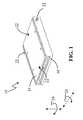
- FIG. 1is an isometric assembled view of a boresighting apparatus, according to one preferred embodiment of this invention
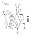
- FIG. 2is an isometric exploded view of a boresighting apparatus, according to one preferred embodiment of this invention.
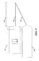
- FIG. 3is an isometric exploded view of a boresighting apparatus, according to one preferred embodiment of this invention.
- FIG. 4is an assembled view with a first device and a second device with a boresighting apparatus, according to one preferred embodiment of this invention
- FIG. 5is an assembled view with a first device and a second device with a boresighting apparatus, according to one preferred embodiment of this invention
- FIG. 6is an assembled view with a first device and a second device with a boresighting apparatus mounting to a pan and tilt, according to one preferred embodiment of this invention.
- FIG. 7is a side sectional view of spherical washers according to one preferred embodiment of this invention.
- Boresight 66includes the optical or physical axis of a device 12 ( FIG. 4 ), such as, for example, scopes, magnifying scopes, view finders, laser finders, cameras, visible-light cameras, infrared cameras, global positioning systems, targeting acquisition systems, visual recognition systems, mapping systems, scanning systems, lighting systems, firearms, lasers, speakers, microphones, satellite receivers, radio wave antennas and/or any other suitable mountable items.
- Devices 12may include fixed and/or variable focal length capabilities, such as a zoom lens.
- Mounting and/or receiving of devices 12may include to stationary objects such as buildings, structures or any other relatively stationary or non-moving location, and mounting of devices 12 may include to mobile or portable objects such as vehicles, cranes or any other relatively non-anchored location.
- Boresight 66 or line of extensionincludes line-of-sight and field of view with respect to the perspective of device 12 .
- Properly calibrating, adjusting, aligning and/or setting-up boresight 66 of device 12may improve accuracy, reception, recognition and/or any other desired characteristic, for example, reducing a distance from the center of a target for a missile or other projectile.
- boresight 66includes the view of a camera, typically, but not necessarily, at a distance from a front of the camera.
- calibration distance 68refers to a point at a fixed distance in front of device 12 with boresight 66 .
- Calibration distance 68may be any suitable distance, for example, from a few centimeters away to distances of a kilometer or more.
- a preferred cameramay utilize a calibration distance of about 100 m to about 1,000 m, preferably about 200 m to about 700 m, and more preferably about 300 m to about 500 m.
- One or more devices 12may be used at the same time, such as, for example, to increase a field of view by placing two or more cameras essentially next to each other forming a side by side configuration or arrangement. Three dimensional or stereo imagery can be made using multiple devices 12 looking at the same object from a different perspective. Any desired number of devices 12 may be arranged with respect to each other to achieve or accomplish the desired result, including an array and/or a panoramic view.
- devices 12may be configured in an overlay or redundant arrangement.
- This overlay arrangementcan be useful when combining signals from different types of devices, such as, for example, a visible-light camera and an infrared (night vision) camera, a camera and a directional microphone, a laser and a digital scanner, and/or any other suitable combination of complimentary and/or supplementary devices 12 .
- Other suitable arrangements of partial overlapping or spacing of imagesmay be utilized.
- apparatus 10 for the boresighting of device 12may include any suitable combination of parts and/or linkages to provide movement or adjustment in at least one direction or vector of boresight 66 ( FIG. 5 ) with respect to a fixed position, such as, for example, the attachment of a second camera to an adapter plate.
- apparatus 10includes or provides one or more degrees of freedom to aid or assist the boresighting of device 12 .
- Degrees of freedominclude a range of motion, such as without limitation, forward and backward, side to side, up and down, axially about a generally horizontal axis, axially about a vertical axis and/or any other suitable movement.
- apparatus 10includes adjustment in, about and/or along a generally horizontal axis and a generally vertical axis.
- tilt angle 24includes the twisting or turning about and/or circumferentially around a generally vertical axis, such as a right and left panning or sliding motion with respect to a fixed position.
- pitch angleincludes the twisting or turning about and/or circumferentially around a generally horizontal transverse axis, such as an up and down panning or sliding motion with respect to a fixed position.
- roll angleincludes the twisting or turning about and/or circumferentially around a generally horizontal longitudinal axis, such as a leaning or tilting sideways panning or sliding motion with respect to a fixed position.
- transverserefers to a generally perpendicular direction with respect to boresight 66 of device 12 .
- longitudinalrefers to a generally parallel and/or coincident direction with respect to boresight 66 of device 12 .
- Apparatus 10may include first plate 14 and second plate 16 which desirably move with respect to each other by and/or with pivot rod 20 ( FIG. 2 ).
- a position of first plate 14 with respect to second plate 16may be held, fixed, locked and/or secured with one or more fasteners 22 , such as two fasteners 22 for each degree of freedom.
- First plate 14may include a generally planar shape of any suitable size or dimension, such as a base the size of device 12 .
- First plate 14may be any suitable material, such as steel, stainless steel, aluminum alloy, plastic, reinforced plastic and any other relatively durable material.
- first plate 14comprises a relatively light-weight, durable, weather resistant member.
- first plate 14includes one or more bores 36 , such as for mounting device 12 .
- Bores 36may include any suitable size and/or shape while being threaded or unthreaded, with or without counterbores.
- first plate 14includes slots and/or cut outs to engage and/or hold at least a portion of a fastener 22 , such as shown in FIG. 3 .
- First plate 14may include one or more cavities 38 , gussets, fillets, chamfers and/or any other suitable reinforcing structural members.
- Second plate 16may include any and/or all of the characteristics and features discussed above with respect to first plate 14 .
- Second plate 16may further include sidewalls 32 to form a channel or channel like structure, such as for receiving at least a portion of first plate 14 .
- Sidewalls 32may include holes, such as threaded connections to receive fastener 22 .
- Apparatus 10may include covers, shields, drains, gasketing, weatherproofing and any other suitable element to aid or facilitate apparatus 10 in the desired operating conditions or environment.
- apparatus 10is at least substantially self draining and not prone to ice build up, such as from freezing and thawing that displaces the first plate from the second plate when installed outside in a northern climate.
- first plate 14 and second plate 16may limit yaw angle 24 to a relatively narrow range of motion, such as about 5 degrees left or right, and/or up or down.
- the range of motionincludes at least about 2.5 degrees, preferably at least about 10 degrees, and most preferably at least about 15 degrees, in either direction of left and/or right movement or motion, such as when a corner of first plate 14 contacts sidewall 32 as a limit.
- first plate 14may include a contoured, round and/or rounded shape, such as may allow increased yaw angles 24 including 360 degrees of freedom or rotation.
- Pivot rod 20may include a bearing, a roller and/or any other suitable movement-allowing coupling. Pivot rod 20 may include any suitable size and/or shape. A larger diameter rod typically may result in an increased adjustment of pitch angle 26 .
- pivot rod 20may have a generally cylindrical shape 30 , such as to allow adjustment of pitch angle 26 about or with respect to pivot rod 20 .
- Pivot rod 20desirably, but not necessarily, includes adjustment of yaw angle 24 and pitch angle 26 with no or without a significant amount of roll angle adjustment.
- pivot rod 20acts a fulcrum or pivot point for pitch angle 26 .
- Yaw angle 24may be adjusted as at least one of the first plate 14 or the second plate 16 rotates on a generally tangential contact point or contact line of pivot rod 20 .
- pivot rod 20allows about at least 2 degrees, preferably at least about 10 degrees, and most preferably at least about 15 degrees or more of up and/or down motion or movement, such as before first plate 14 contacts 16 .
- Pivot rod 20may further include any suitable lubricating substances such as a lubricating oil, grease, lithium grease, silicon grease and/or any other suitable friction-reducing compound. Lubricating substances may also help or assist in maintaining a position or location of pivot rod 20 , such as during field installation.
- suitable lubricating substancessuch as a lubricating oil, grease, lithium grease, silicon grease and/or any other suitable friction-reducing compound.
- Lubricating substancesmay also help or assist in maintaining a position or location of pivot rod 20 , such as during field installation.
- first plate 14 and/or second plate 16may include recess 34 , seat and/or groove to receive or accept at least a portion of pivot rod 20 .
- recess 34includes a sufficient width to allow adjustment of yaw angle 24 without significant binding and/or misalignment of first plate 14 with respect to second plate 16 .
- recess 34includes a tight fit with pivot rod 20 to allow little or no slop or play in the assembly.
- Fastener 22may include any suitable anchoring, affixing, attaching and/or locking device.
- Common fastenersinclude hand or tool operable mechanical unions, such as, for example, screws, cap screws, thumb screws 64 ( FIG. 6 ), bolts, hex bolts, nuts, lock nuts, washers, lock washers, spherical washers 70 ( FIG. 7 ), clevis pins, and any other suitable mechanism.
- Fasteners 22may include additional materials, such as adhesive thread locking compounds used to prevent vibration related loosening.
- Fastener 22may also include more permanent items, such as welds, urethane adhesives and epoxy adhesives.
- Fastener 22can be of any desired size or dimension in any suitable material. Suitable materials may include steel, carbon steel, stainless steel, nylon, alloys, and any other relatively high tensile strength material. Typically, but not necessarily, fastener 22 forms a physical union between first plate 14 and second plate 16 .
- fastener 22can be calibrated to correspond to associated movement of device 12 , such as, for example, a quarter turn of fastener 22 results in a half a degree of movement of yaw angle 24 .
- tighter tolerances, such as a finer threadmay allow finer calibration than a coarse thread.
- fastener 22includes front bolt 46 , rear bolt 48 , nut 42 , washer 44 , adjustment rod 40 , side screw 50 and opposite side screw 52 .
- adjustment rod 40in combination with a receiving slot or groove, allows first plate 14 and second plate 16 to adjust with respect to each other without binding or grabbing of fastener 22 in a location or position other than desired.
- spherical washers 70may provide adjustment without binding of first plate 14 and second plate 16 .
- Other non-binding or anti-seizing arrangements or configurationsare possible.
- apparatus 10includes front bolt 46 and rear bolt 48 , such as to fix and/or set pitch angle 26 .
- Front bolt 46 and rear bolt 48may include any of the qualities and/or characteristics discussed above with respect to fastener 22 .
- front bolt 46 and rear bolt 48may include one quarter inch diameter bolts with 28 threads per inch. Other diameters of standard, English or metric devices in varying thread pitches and/or lengths are possible.
- front bolt 46engages at least a portion of first plate 14 and/or at least a portion of second plate 16 to at least partially affix first plate 14 with respect to second plate 16 , such as when adjusted or tightened in combination with rear bolt 48 .
- front bolt 48couples with adjustment rod 40 , spherical washers 70 , spherical nut, nut 42 and/or any other suitable antiseizing or antibinding configuration or device.
- Rear bolt 48may include any of the qualities and/or characteristics discussed above with respect to front bolt 46 .
- rear boltengages first plate 14 and second plate 16 with nut 42 , such as a hex nut of corresponding diameter and thread pitch to rear bolt 48 .
- Front bolt 46 and rear bolt 48may also engage washer 44 , such as a flat washer or a lock washer.
- washer 44such as a flat washer or a lock washer.
- at least a portion of nut 42resides within a slot, recess or groove of second plate 16 .
- Adjustment rod 40may include a generally cylindrical shape having a substantially circular cross section and/or any other suitable antibinding geometry. Typical antibinding geometries include pivot points, rotation areas, sliding regions and/or any other suitable configuration to allow or facilitate movement of one member with respect to another, such as when fastener 22 is disengaged. Desirably, adjustment rod 40 includes a threaded hole to engage at least a portion of front bolt 46 . Generally, at least a portion of adjustment rod 40 resides within a slot, recess, or groove of second plate 16 .
- apparatus 10includes side screw 50 and opposite side screw 52 , such as to fix and/or set yaw angle 24 .
- Side screw 50 and opposite side screw 52may include all the characteristics discussed above with respect to fastener 22 , front bolt 46 and/or rear bolt 48 .
- side screw 50 and opposite side screw 52do not require tools, such as for field adjustment.
- side screw 50 and opposite side screw 52include thumb screws 64 ( FIG. 6 ).
- side screw 50engages at least a portion of first plate 14 and/or at least a portion of second plate 16 to at least partially affix first plate with respect to second plate when adjusted or tightened in combination with opposite side screw 52 .
- Side screw 50 and opposite side screw 52may thread into or engage at least a portion of sidewall 32 .
- apparatus 10mounts to structure 18 ( FIG. 4 ), such as, for example a mounting plate, an adapting plate and/or any other suitable body or member.
- structure 18includes one or more devices 12 mounting or anchoring to and/or upon it.
- at least one of devices 12has at least a portion of apparatus 10 between and/or connecting structure 18 and device 12 .
- any number or combination of suitable spacer, washers or blocksmay mount device 12 .
- a blockhaving about the same dimensions of apparatus 10 for boresighting a first device 60 being placed under second device 62 .
- FIG. 5shows first device 60 having boresight 66 and second device 62 having boresight 66 .
- first device 60resides or sits on apparatus 10 to allow adjustment of boresight 66 , such as intersecting the boresight 66 of second device 62 at calibration distance 68 or fixed position away from or in front of devices 60 , 62 .
- the arrangement depicted in FIG. 5results in an overlapping boresight, such as forming a redundant image. Redundant images may include signals from visible light camera 54 and infrared camera 56 , such as, for example, as shown in FIG. 6 .
- structure 18further includes pan and tilt 58 .
- Pan and tilt 58desirably provides at least two axes of controlled movement with one or more mechanical, electrical, pneumatic and/or hydraulic actuators.
- This inventionalso includes methods of boresighting one or more devices 12 .
- the method for boresighting a first device 60 with respect to a boresight 66 of second device 62includes mounting first device 60 on first plate 14 of apparatus 10 , wherein the first plate 14 adjustably engages second plate 16 by pivot rod 20 and second plate 16 mounts with respect to pan and tilt 58 .
- Second device 62mounts on pan and tilt 58 .
- the methodalso includes calibrating least one of yaw angle 24 and pitch angle 26 of first plate 14 with respect to second plate 16 and fixing the position of first plate 14 with respect to second plate 16 by at least one fastener 22 .
- Calibratingmay include intersecting boresight 66 of first device 60 with boresight 66 of second device 62 .
- calibratingmay include aligning boresights 66 at least generally parallel with respect to each other.
- the methodmay include loosening front bolt 46 , back bolt 48 , side screw 50 and opposite side screw 52 , moving first plate 14 to adjust yaw angle 24 to the desired position of first plate 14 before tightening side screw 50 and opposite side screw 52 .
- the methodmay also include moving first plate 14 to adjust pitch angle 26 to the desired position of first plate 14 with respect to pivot rod 20 by moving back bolt 48 and then tightening front bolt 46 .
- the methodmay include tightening side screw 50 and opposite side screw 52 after tightening front fixing bolt 46 .
Landscapes
- Engineering & Computer Science (AREA)
- General Engineering & Computer Science (AREA)
- Mechanical Engineering (AREA)
- Physics & Mathematics (AREA)
- Optics & Photonics (AREA)
- Accessories Of Cameras (AREA)
Abstract
Description
Claims (22)
Priority Applications (1)
| Application Number | Priority Date | Filing Date | Title |
|---|---|---|---|
| US11/899,855US7798453B2 (en) | 2007-09-07 | 2007-09-07 | Boresight apparatus and method of use |
Applications Claiming Priority (1)
| Application Number | Priority Date | Filing Date | Title |
|---|---|---|---|
| US11/899,855US7798453B2 (en) | 2007-09-07 | 2007-09-07 | Boresight apparatus and method of use |
Publications (2)
| Publication Number | Publication Date |
|---|---|
| US20090065666A1 US20090065666A1 (en) | 2009-03-12 |
| US7798453B2true US7798453B2 (en) | 2010-09-21 |
Family
ID=40430812
Family Applications (1)
| Application Number | Title | Priority Date | Filing Date |
|---|---|---|---|
| US11/899,855Active2028-05-31US7798453B2 (en) | 2007-09-07 | 2007-09-07 | Boresight apparatus and method of use |
Country Status (1)
| Country | Link |
|---|---|
| US (1) | US7798453B2 (en) |
Cited By (28)
| Publication number | Priority date | Publication date | Assignee | Title |
|---|---|---|---|---|
| US8625106B2 (en) | 2009-07-22 | 2014-01-07 | Faro Technologies, Inc. | Method for optically scanning and measuring an object |
| US8699007B2 (en) | 2010-07-26 | 2014-04-15 | Faro Technologies, Inc. | Device for optically scanning and measuring an environment |
| US8699036B2 (en) | 2010-07-29 | 2014-04-15 | Faro Technologies, Inc. | Device for optically scanning and measuring an environment |
| US8705012B2 (en) | 2010-07-26 | 2014-04-22 | Faro Technologies, Inc. | Device for optically scanning and measuring an environment |
| US8730477B2 (en)* | 2010-07-26 | 2014-05-20 | Faro Technologies, Inc. | Device for optically scanning and measuring an environment |
| US8830485B2 (en) | 2012-08-17 | 2014-09-09 | Faro Technologies, Inc. | Device for optically scanning and measuring an environment |
| US8896819B2 (en) | 2009-11-20 | 2014-11-25 | Faro Technologies, Inc. | Device for optically scanning and measuring an environment |
| US8997362B2 (en) | 2012-07-17 | 2015-04-07 | Faro Technologies, Inc. | Portable articulated arm coordinate measuring machine with optical communications bus |
| US9009000B2 (en) | 2010-01-20 | 2015-04-14 | Faro Technologies, Inc. | Method for evaluating mounting stability of articulated arm coordinate measurement machine using inclinometers |
| US9113023B2 (en) | 2009-11-20 | 2015-08-18 | Faro Technologies, Inc. | Three-dimensional scanner with spectroscopic energy detector |
| US9163922B2 (en) | 2010-01-20 | 2015-10-20 | Faro Technologies, Inc. | Coordinate measurement machine with distance meter and camera to determine dimensions within camera images |
| US9168654B2 (en) | 2010-11-16 | 2015-10-27 | Faro Technologies, Inc. | Coordinate measuring machines with dual layer arm |
| US9182211B2 (en) | 2011-12-06 | 2015-11-10 | Honeywell International Inc. | Field interchangable boresight mounting system and calibration method |
| US9210288B2 (en) | 2009-11-20 | 2015-12-08 | Faro Technologies, Inc. | Three-dimensional scanner with dichroic beam splitters to capture a variety of signals |
| USRE45854E1 (en) | 2006-07-03 | 2016-01-19 | Faro Technologies, Inc. | Method and an apparatus for capturing three-dimensional data of an area of space |
| US9329271B2 (en) | 2010-05-10 | 2016-05-03 | Faro Technologies, Inc. | Method for optically scanning and measuring an environment |
| US9372265B2 (en) | 2012-10-05 | 2016-06-21 | Faro Technologies, Inc. | Intermediate two-dimensional scanning with a three-dimensional scanner to speed registration |
| US9417316B2 (en) | 2009-11-20 | 2016-08-16 | Faro Technologies, Inc. | Device for optically scanning and measuring an environment |
| US9417056B2 (en) | 2012-01-25 | 2016-08-16 | Faro Technologies, Inc. | Device for optically scanning and measuring an environment |
| US9513107B2 (en) | 2012-10-05 | 2016-12-06 | Faro Technologies, Inc. | Registration calculation between three-dimensional (3D) scans based on two-dimensional (2D) scan data from a 3D scanner |
| US9529083B2 (en) | 2009-11-20 | 2016-12-27 | Faro Technologies, Inc. | Three-dimensional scanner with enhanced spectroscopic energy detector |
| US9551575B2 (en) | 2009-03-25 | 2017-01-24 | Faro Technologies, Inc. | Laser scanner having a multi-color light source and real-time color receiver |
| US9607239B2 (en) | 2010-01-20 | 2017-03-28 | Faro Technologies, Inc. | Articulated arm coordinate measurement machine having a 2D camera and method of obtaining 3D representations |
| US9628775B2 (en) | 2010-01-20 | 2017-04-18 | Faro Technologies, Inc. | Articulated arm coordinate measurement machine having a 2D camera and method of obtaining 3D representations |
| US9709359B1 (en)* | 2011-12-05 | 2017-07-18 | James Travis Robbins | Fixed optic for boresight |
| US10067231B2 (en) | 2012-10-05 | 2018-09-04 | Faro Technologies, Inc. | Registration calculation of three-dimensional scanner data performed between scans based on measurements by two-dimensional scanner |
| US10175037B2 (en) | 2015-12-27 | 2019-01-08 | Faro Technologies, Inc. | 3-D measuring device with battery pack |
| US10281259B2 (en) | 2010-01-20 | 2019-05-07 | Faro Technologies, Inc. | Articulated arm coordinate measurement machine that uses a 2D camera to determine 3D coordinates of smoothly continuous edge features |
Families Citing this family (5)
| Publication number | Priority date | Publication date | Assignee | Title |
|---|---|---|---|---|
| CN211825673U (en)* | 2015-12-07 | 2020-10-30 | 菲力尔系统公司 | Image forming apparatus with a plurality of image forming units |
| US11265387B2 (en)* | 2019-11-13 | 2022-03-01 | At&T Intellectual Property I, L.P. | Synchronizing multiple user devices in an immersive media environment using time-of-flight light patterns |
| DE112020000185T5 (en)* | 2019-11-15 | 2021-09-02 | Fnss Savunma Si̇stemleri̇ Anoni̇m Şi̇rketi̇ | SINGLE PLATE TARGET CONTROL MECHANISM WITH INDEPENDENT MOVEMENT AND LOCKABILITY |
| CN114455086B (en)* | 2021-12-30 | 2023-06-06 | 哈瓦国际航空技术(深圳)有限公司 | Look into and beat integrative cloud platform and unmanned aerial vehicle |
| US12281877B2 (en)* | 2023-07-11 | 2025-04-22 | Muniec Arms Llc | Firearm accessory mounting assembly, firearm containing the same, and method of attachment |
Citations (10)
| Publication number | Priority date | Publication date | Assignee | Title |
|---|---|---|---|---|
| US4533105A (en)* | 1984-04-27 | 1985-08-06 | Zenith Electronics Corporation | Tiltable display monitor assembly |
| US4838509A (en)* | 1986-08-23 | 1989-06-13 | Daimler-Benz Aktiengesellschaft | Tilt-adjustable seat cushion for a vehicle seat |
| US5933668A (en) | 1997-11-12 | 1999-08-03 | Hyers; Jon W. | Camera mounting apparatus |
| US20050092884A1 (en)* | 2003-07-01 | 2005-05-05 | Puu Rong Industries Co., Ltd. | Keyboard support bracket structure |
| US20060110151A1 (en)* | 2004-11-25 | 2006-05-25 | Elmo Company, Limited | Imaging device |
| US20060269278A1 (en)* | 2004-10-15 | 2006-11-30 | Kenoyer Michael L | Coordinated camera pan tilt mechanism |
| US7185862B1 (en)* | 2005-10-04 | 2007-03-06 | Jen Yu Yang | Mounting platform assembly for a stand device |
| US20070248353A1 (en)* | 2006-04-19 | 2007-10-25 | Meiric Chen | Lamp device with rotatable legs |
| US20090179127A1 (en)* | 2004-06-30 | 2009-07-16 | Btr Robotics Limited Liability Company | Pan systems |
| US7614805B2 (en)* | 2006-11-07 | 2009-11-10 | Joseph Showalter | Image capture device mounting assembly for firearm |
- 2007
- 2007-09-07USUS11/899,855patent/US7798453B2/enactiveActive
Patent Citations (10)
| Publication number | Priority date | Publication date | Assignee | Title |
|---|---|---|---|---|
| US4533105A (en)* | 1984-04-27 | 1985-08-06 | Zenith Electronics Corporation | Tiltable display monitor assembly |
| US4838509A (en)* | 1986-08-23 | 1989-06-13 | Daimler-Benz Aktiengesellschaft | Tilt-adjustable seat cushion for a vehicle seat |
| US5933668A (en) | 1997-11-12 | 1999-08-03 | Hyers; Jon W. | Camera mounting apparatus |
| US20050092884A1 (en)* | 2003-07-01 | 2005-05-05 | Puu Rong Industries Co., Ltd. | Keyboard support bracket structure |
| US20090179127A1 (en)* | 2004-06-30 | 2009-07-16 | Btr Robotics Limited Liability Company | Pan systems |
| US20060269278A1 (en)* | 2004-10-15 | 2006-11-30 | Kenoyer Michael L | Coordinated camera pan tilt mechanism |
| US20060110151A1 (en)* | 2004-11-25 | 2006-05-25 | Elmo Company, Limited | Imaging device |
| US7185862B1 (en)* | 2005-10-04 | 2007-03-06 | Jen Yu Yang | Mounting platform assembly for a stand device |
| US20070248353A1 (en)* | 2006-04-19 | 2007-10-25 | Meiric Chen | Lamp device with rotatable legs |
| US7614805B2 (en)* | 2006-11-07 | 2009-11-10 | Joseph Showalter | Image capture device mounting assembly for firearm |
Cited By (38)
| Publication number | Priority date | Publication date | Assignee | Title |
|---|---|---|---|---|
| USRE45854E1 (en) | 2006-07-03 | 2016-01-19 | Faro Technologies, Inc. | Method and an apparatus for capturing three-dimensional data of an area of space |
| US9551575B2 (en) | 2009-03-25 | 2017-01-24 | Faro Technologies, Inc. | Laser scanner having a multi-color light source and real-time color receiver |
| US8625106B2 (en) | 2009-07-22 | 2014-01-07 | Faro Technologies, Inc. | Method for optically scanning and measuring an object |
| US9113023B2 (en) | 2009-11-20 | 2015-08-18 | Faro Technologies, Inc. | Three-dimensional scanner with spectroscopic energy detector |
| US9529083B2 (en) | 2009-11-20 | 2016-12-27 | Faro Technologies, Inc. | Three-dimensional scanner with enhanced spectroscopic energy detector |
| US9417316B2 (en) | 2009-11-20 | 2016-08-16 | Faro Technologies, Inc. | Device for optically scanning and measuring an environment |
| US8896819B2 (en) | 2009-11-20 | 2014-11-25 | Faro Technologies, Inc. | Device for optically scanning and measuring an environment |
| US9210288B2 (en) | 2009-11-20 | 2015-12-08 | Faro Technologies, Inc. | Three-dimensional scanner with dichroic beam splitters to capture a variety of signals |
| US9163922B2 (en) | 2010-01-20 | 2015-10-20 | Faro Technologies, Inc. | Coordinate measurement machine with distance meter and camera to determine dimensions within camera images |
| US9009000B2 (en) | 2010-01-20 | 2015-04-14 | Faro Technologies, Inc. | Method for evaluating mounting stability of articulated arm coordinate measurement machine using inclinometers |
| US9628775B2 (en) | 2010-01-20 | 2017-04-18 | Faro Technologies, Inc. | Articulated arm coordinate measurement machine having a 2D camera and method of obtaining 3D representations |
| US9607239B2 (en) | 2010-01-20 | 2017-03-28 | Faro Technologies, Inc. | Articulated arm coordinate measurement machine having a 2D camera and method of obtaining 3D representations |
| US10060722B2 (en) | 2010-01-20 | 2018-08-28 | Faro Technologies, Inc. | Articulated arm coordinate measurement machine having a 2D camera and method of obtaining 3D representations |
| US10281259B2 (en) | 2010-01-20 | 2019-05-07 | Faro Technologies, Inc. | Articulated arm coordinate measurement machine that uses a 2D camera to determine 3D coordinates of smoothly continuous edge features |
| US9684078B2 (en) | 2010-05-10 | 2017-06-20 | Faro Technologies, Inc. | Method for optically scanning and measuring an environment |
| US9329271B2 (en) | 2010-05-10 | 2016-05-03 | Faro Technologies, Inc. | Method for optically scanning and measuring an environment |
| US8705012B2 (en) | 2010-07-26 | 2014-04-22 | Faro Technologies, Inc. | Device for optically scanning and measuring an environment |
| US8730477B2 (en)* | 2010-07-26 | 2014-05-20 | Faro Technologies, Inc. | Device for optically scanning and measuring an environment |
| US8699007B2 (en) | 2010-07-26 | 2014-04-15 | Faro Technologies, Inc. | Device for optically scanning and measuring an environment |
| US8699036B2 (en) | 2010-07-29 | 2014-04-15 | Faro Technologies, Inc. | Device for optically scanning and measuring an environment |
| US9168654B2 (en) | 2010-11-16 | 2015-10-27 | Faro Technologies, Inc. | Coordinate measuring machines with dual layer arm |
| US9709359B1 (en)* | 2011-12-05 | 2017-07-18 | James Travis Robbins | Fixed optic for boresight |
| US9182211B2 (en) | 2011-12-06 | 2015-11-10 | Honeywell International Inc. | Field interchangable boresight mounting system and calibration method |
| US9417056B2 (en) | 2012-01-25 | 2016-08-16 | Faro Technologies, Inc. | Device for optically scanning and measuring an environment |
| US8997362B2 (en) | 2012-07-17 | 2015-04-07 | Faro Technologies, Inc. | Portable articulated arm coordinate measuring machine with optical communications bus |
| US8830485B2 (en) | 2012-08-17 | 2014-09-09 | Faro Technologies, Inc. | Device for optically scanning and measuring an environment |
| US9739886B2 (en) | 2012-10-05 | 2017-08-22 | Faro Technologies, Inc. | Using a two-dimensional scanner to speed registration of three-dimensional scan data |
| US9618620B2 (en) | 2012-10-05 | 2017-04-11 | Faro Technologies, Inc. | Using depth-camera images to speed registration of three-dimensional scans |
| US9746559B2 (en) | 2012-10-05 | 2017-08-29 | Faro Technologies, Inc. | Using two-dimensional camera images to speed registration of three-dimensional scans |
| US9372265B2 (en) | 2012-10-05 | 2016-06-21 | Faro Technologies, Inc. | Intermediate two-dimensional scanning with a three-dimensional scanner to speed registration |
| US10067231B2 (en) | 2012-10-05 | 2018-09-04 | Faro Technologies, Inc. | Registration calculation of three-dimensional scanner data performed between scans based on measurements by two-dimensional scanner |
| US10203413B2 (en) | 2012-10-05 | 2019-02-12 | Faro Technologies, Inc. | Using a two-dimensional scanner to speed registration of three-dimensional scan data |
| US9513107B2 (en) | 2012-10-05 | 2016-12-06 | Faro Technologies, Inc. | Registration calculation between three-dimensional (3D) scans based on two-dimensional (2D) scan data from a 3D scanner |
| US10739458B2 (en) | 2012-10-05 | 2020-08-11 | Faro Technologies, Inc. | Using two-dimensional camera images to speed registration of three-dimensional scans |
| US11035955B2 (en) | 2012-10-05 | 2021-06-15 | Faro Technologies, Inc. | Registration calculation of three-dimensional scanner data performed between scans based on measurements by two-dimensional scanner |
| US11112501B2 (en) | 2012-10-05 | 2021-09-07 | Faro Technologies, Inc. | Using a two-dimensional scanner to speed registration of three-dimensional scan data |
| US11815600B2 (en) | 2012-10-05 | 2023-11-14 | Faro Technologies, Inc. | Using a two-dimensional scanner to speed registration of three-dimensional scan data |
| US10175037B2 (en) | 2015-12-27 | 2019-01-08 | Faro Technologies, Inc. | 3-D measuring device with battery pack |
Also Published As
| Publication number | Publication date |
|---|---|
| US20090065666A1 (en) | 2009-03-12 |
Similar Documents
| Publication | Publication Date | Title |
|---|---|---|
| US7798453B2 (en) | Boresight apparatus and method of use | |
| US11181338B2 (en) | Tactical-gear-rails connector-adapter system apparatus and method | |
| EP1705745B1 (en) | Antenna mount with fine adjustment cam | |
| US5086566A (en) | Adjustable telescopic sight mount | |
| EP2435777B1 (en) | Solid state flexure for pointing device | |
| US12269396B2 (en) | Camera mounting device for a vehicle | |
| US8327574B2 (en) | System for mounting an accessory to a firearm | |
| US20200321678A1 (en) | Adjustable antenna mount | |
| US20210336322A1 (en) | Fastening device and associated method | |
| US12352531B2 (en) | Weapon anti-cant indicator | |
| CA2802459C (en) | Adjustable mounting assembly for an antenna mast | |
| US8350778B2 (en) | Adjustment method for dish antenna | |
| CN116848367A (en) | Apparatus and method | |
| US20180023926A1 (en) | Adjusting assembly and method thereof | |
| US6338219B1 (en) | Bracket-integrated back-up optical sight | |
| CN1606192A (en) | Fixing structure using a couple of screws and antenna unit having the same | |
| US7522356B1 (en) | Sight having an asymmetric field of view and its manufacture | |
| EP1705746B1 (en) | High resolution orientation adjusting arrangement for feed assembly |
Legal Events
| Date | Code | Title | Description |
|---|---|---|---|
| AS | Assignment | Owner name:QUICKSET INTERNATIONAL, INC., ILLINOIS Free format text:ASSIGNMENT OF ASSIGNORS INTEREST;ASSIGNORS:MANINGO, JESSIE IAN;ABBOTT, CHRISTOPHER LEE;LUTZ, JAMES ROBERT;REEL/FRAME:019837/0023 Effective date:20070829 | |
| STCF | Information on status: patent grant | Free format text:PATENTED CASE | |
| AS | Assignment | Owner name:HSBC BANK USA, NATIONAL ASSOCIATION, NEW YORK Free format text:NOTICE OF SECURITY INTEREST IN PATENTS AND PATENT APPLICATIONS;ASSIGNOR:QUICKSET INTERNATIONAL, INC.;REEL/FRAME:026003/0132 Effective date:20110318 | |
| AS | Assignment | Owner name:MOOG INC., NEW YORK Free format text:MERGER;ASSIGNOR:QUICKSET INTERNATIONAL, INC.;REEL/FRAME:031892/0750 Effective date:20131205 | |
| FPAY | Fee payment | Year of fee payment:4 | |
| MAFP | Maintenance fee payment | Free format text:PAYMENT OF MAINTENANCE FEE, 8TH YEAR, LARGE ENTITY (ORIGINAL EVENT CODE: M1552) Year of fee payment:8 | |
| MAFP | Maintenance fee payment | Free format text:PAYMENT OF MAINTENANCE FEE, 12TH YEAR, LARGE ENTITY (ORIGINAL EVENT CODE: M1553); ENTITY STATUS OF PATENT OWNER: LARGE ENTITY Year of fee payment:12 | |
| AS | Assignment | Owner name:QUICKSET DEFENSE TECHNOLOGIES, LLC, ILLINOIS Free format text:ASSIGNMENT OF ASSIGNORS INTEREST;ASSIGNOR:MOOG INC.;REEL/FRAME:061186/0815 Effective date:20220920 | |
| AS | Assignment | Owner name:MOOG INC., NEW YORK Free format text:RELEASE BY SECURED PARTY;ASSIGNOR:HSBC BANK USA, NATIONAL ASSOCIATION;REEL/FRAME:061255/0360 Effective date:20220920 |