US7798260B2 - Track vehicle having drive and suspension systems - Google Patents
Track vehicle having drive and suspension systemsDownload PDFInfo
- Publication number
- US7798260B2 US7798260B2US11/843,331US84333107AUS7798260B2US 7798260 B2US7798260 B2US 7798260B2US 84333107 AUS84333107 AUS 84333107AUS 7798260 B2US7798260 B2US 7798260B2
- Authority
- US
- United States
- Prior art keywords
- track
- carriages
- drive shafts
- frame
- cab
- Prior art date
- Legal status (The legal status is an assumption and is not a legal conclusion. Google has not performed a legal analysis and makes no representation as to the accuracy of the status listed.)
- Active, expires
Links
Images


Classifications
- B—PERFORMING OPERATIONS; TRANSPORTING
- B62—LAND VEHICLES FOR TRAVELLING OTHERWISE THAN ON RAILS
- B62D—MOTOR VEHICLES; TRAILERS
- B62D33/00—Superstructures for load-carrying vehicles
- B62D33/06—Drivers' cabs
- B62D33/0604—Cabs insulated against vibrations or noise, e.g. with elastic suspension
- B—PERFORMING OPERATIONS; TRANSPORTING
- B62—LAND VEHICLES FOR TRAVELLING OTHERWISE THAN ON RAILS
- B62D—MOTOR VEHICLES; TRAILERS
- B62D55/00—Endless track vehicles
- B62D55/08—Endless track units; Parts thereof
- B62D55/104—Suspension devices for wheels, rollers, bogies or frames
- B—PERFORMING OPERATIONS; TRANSPORTING
- B62—LAND VEHICLES FOR TRAVELLING OTHERWISE THAN ON RAILS
- B62D—MOTOR VEHICLES; TRAILERS
- B62D55/00—Endless track vehicles
- B62D55/08—Endless track units; Parts thereof
- B62D55/12—Arrangement, location, or adaptation of driving sprockets
- B62D55/125—Final drives
Definitions
- the present inventionrelates to construction vehicles. Specifically, compact track loaders that include suspension systems.
- track vehicleshave not had suspension systems. Instead, axles and wheels support the track for rotation and the vehicle frame is welded to these axles. Also, track vehicles are often provided with high-torque, low-speed motors, which are typically large and expensive.
- the inventionprovides a track vehicle comprising: a cab operable to support an operator; left and right motors each rotating an output shaft at a first speed; a speed reduction system operably coupled to each output shaft; left and right drive shafts being driven by the speed reduction system at a second speed that is slower than the first speed; left and right drive sprockets mounted for rotation with the respective left and right drive shafts; left and right track carriages supporting the cab; and left and right tracks mounted for rotation about the track carriages in response to rotation of the respective left and right drive shafts, wherein the left and right tracks are driven by the left and right drive sprockets to move the track vehicle along a ground surface.
- the inventionprovides a track vehicle comprising: a frame operable to support an operator; first and second motors rotating respective output shafts; first and second drive shafts being driven in response to rotation of the output shafts; first and second drive sprockets mounted for rotation with the drive shafts; first and second track carriages supporting the frame; a speed reduction system coupled between the output shafts and the drive shafts, such that the drive shafts are rotated at a slower speed than the output shafts speed of rotation; and first and second tracks mounted for rotation about the track carriages in response to rotation of the drive sprockets, wherein the first and second tracks are rotated around the respective first and second track carriages in response to the first and second motors, such that the track vehicle is moveable along a ground surface, in response to the movement of the first and second tracks.
- the inventionprovides a method of operating a track vehicle having a body frame, first and second motors having first and second motor shafts, respectively, first and second track carriages pivotally mounted to the body frame, first and second tracks rotatable around the respective first and second track carriages, first and second track drive shafts rotatable to cause rotation of the first and second tracks about the first and second track carriages, a first speed reduction system interconnected between the first motor shaft and the first track drive shaft, and a second speed reduction system interconnected between the second motor shaft and the second track drive shaft.
- the methodcomprises operating the first and second motors at first speeds; driving the first and second track drive shafts through the respective first and second speed reduction systems at second speeds slower than the first speeds; driving rotation of the first and second tracks around the respective first and second track carriages in response to rotation of the respective first and second track drive shafts; and pivoting the carriages with respect to the body frame.
- FIG. 1is a perspective view of a track vehicle.
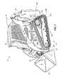
- FIG. 2is a partially exploded perspective view of a first track drive arrangement for the track vehicle.
- FIG. 3is a partially exploded perspective view of a second track drive arrangement for the track vehicle.
- FIG. 4is a perspective view of one of the track carriages of the track vehicle, including a first suspension system arrangement.
- FIG. 5is a perspective view of one of the track carriages of the track vehicle, including a second suspension system arrangement.
- FIG. 1illustrates a compact track loader vehicle 10 according to one embodiment of the invention.
- the compact track loader 10includes a body frame 20 , a hydraulic system 25 , an engine 30 , a cab 35 , a pair of support arms or masts 40 , a pair of lift arms 45 , a bucket 50 , a pair of lift actuators 55 , a pair of support links 60 , a pair of attachment actuators 65 , and a pair of track carriages or assemblies 70 (one on each of the opposite sides of the compact track loader 10 ).
- the engine 30drives one or more hydraulic pumps within the hydraulic system 25 , and the pumps provide a flow of hydraulic fluid to the actuators 55 , 65 and hydraulic drive systems to operate the track assemblies 70 (discussed in more detail below).
- the operatorcontrols the hydraulic drive system 25 , and therefore operates the compact track loader 10 , with controls in the cab 35 .
- the controlsmove spool valves (not shown) to direct the hydraulic fluid to the lift actuators 55 and the attachment actuators 65 .
- the support arms 40are pivotably mounted to the body frame 20 , the lift arms 45 are pivotably mounted to the support arms 40 , and an attachment interface 75 is pivotably mounted to the lift arms 45 .
- the lift actuators 55are interconnected between the lift arms 45 and the body frame 20 and extend and retract in response to the operator's control of the hydraulic system 25 to cause the lift arms 45 to pivot in raising and lowering directions with respect to the support arms 40 and body frame 20 .
- the support links 60provide additional support and stability to the lift arms 45 .
- the attachment actuators 65are interconnected between the lift arms 45 and the attachment interface 75 , and extend and retract in response to the operator's control of the hydraulic system 25 to pivot the bucket 50 in curling and dumping directions with respect to the lift arms 45 .
- the illustrated attachmentis a bucket 50
- the compact track loadermay in other embodiments include other attachments, including without limitation, augers, jack hammers, trenchers, grapples, rotary sweepers, stump grinders, saws, concrete mixers, pumps, chippers, snow throwers, rotary cutters, and backhoes.
- the attachment actuators 65may be used to raise, lower, tilt, or pivot the attachments for their intended purposes.
- Each hydraulic drive system 200includes a hydraulic motor 210 , a small chain sprocket 220 , a large chain sprocket 230 , a chain 240 extending around the small and large chain sprockets 220 , 230 , and a track drive shaft 250 .
- the flow of hydraulic fluid in the hydraulic system 25drives operation of the left and right hydraulic motors 210 .
- the small chain sprockets 220are mounted to the output shafts of the motors 210 and rotate in response to operation of the motors 210 .
- the chains 240transfer torque from the left and right small chain sprockets 220 to the respective left and right large chain sprockets 230 , to cause rotation of the large chain sprockets 230 .
- the large chain sprockets 230are mounted for rotation with the track drive shafts 250 , and the track drive shafts 250 therefore rotate in response to rotation of the large chain sprockets 230 under the influence of the motors 210 .
- the small chain sprocket 220 , large chain sprocket 230 , and chain 240may be referred to as a speed reduction system operable to transfer torque from the motor 210 output shafts to the track drive shafts 250 .
- speed reduction systemsincluding but not limited to gear trains and pulley and belt systems, may be used in the present invention and the illustrated speed reduction system should not be regarded as limiting.
- the speed reduction derived from driving the large chain sprockets 230 off of the small chain sprockets 220increases the torque output on the track drive shafts 250 . Consequently, high speed, low torque motors can be used as the motors 210 .
- FIG. 3illustrates an alternate configuration of the drive system 200 in which the motors 210 are positioned in the middle of the body frame 20 and the chains 240 run along the inner sides of the side walls of the body frame 20 .
- the configuration illustrated in FIG. 2may be termed a “center mounted” chain reduction and the configuration illustrated in FIG. 3 may be termed a “side mounted” chain reduction.
- Both configurationsmay employ chain covers 260 to cover the chain reductions.
- Both the center mounted and the side mounted chain reduction configurations and the respective chain covers 260are mounted to the body frame 20 within the footprint of the cab 35 .
- the footprint of the cabis herein defined as being contained within a vertical projection of the cab 35 .
- each (e.g., left and right) track assembly 70includes a drive sprocket 300 , a track frame 310 , front and rear driven sprockets 320 , 330 , a plurality of rollers 340 , and a track 350 .
- the left and right drive sprockets 300are fixed for rotation with the respective left and right track drive shafts 250 , and engage lugs on the inner surface of the track 350 to cause to the track to rotate around the track frame 310 .
- the front and rear driven sprockets 320 , 330 and rollers 340are mounted to the track frame 310 and maintain tension in the track 350 and may be configured to bias the track into engagement with the ground.
- each suspension system 400includes a swivel bearing 410 mounted toward the rear of the track frame 310 and a shock assembly 420 , 420 ′ mounted on a bracket 430 that is rigidly mounted to a front portion of the track frame 310 .
- the swivel bearing 410extends around the track drive shaft 250 and facilitates pivoting of the track assembly 70 about the track drive shaft 250 .
- the shock assembly 420 illustrated in FIG. 4is of a type that has a piston and cylinder shock 440 and an accumulator 450 .
- the bottom of the shock 440is secured by way of a pin 460 to the bracket 430 , and the top of the shock 440 is connected to the cab 35 .
- the accumulator 450may be taken out of communication (e.g., by closing a valve) with the shock 440 to create a stiff suspension.
- the shock assembly 420 ′ illustrated in FIG. 5is of a type having a shock and a coil spring to provide spring bias and dampening functionality to the suspension system 400 .
- the shock assemblies 420 , 420 ′are similar to ride control systems used to absorb bouncing movement of the boom of a construction vehicle as the vehicle travels. Examples of such ride control systems are described in U.S. Pat. Nos. 6,634,653 and 7,194,858, and in U.S. Patent Application Publication Nos. 2006/0075750, 2006/0101815, and 2005/0284711, the entire contents of the foregoing patents and published patent applications being incorporated herein by reference. Additionally, suitable accumulator and valve assemblies for the shock assembly 420 are publicly available from Americorp, Inc. of New Mexico as Kit No. 7106063.
Landscapes
- Engineering & Computer Science (AREA)
- Chemical & Material Sciences (AREA)
- Combustion & Propulsion (AREA)
- Transportation (AREA)
- Mechanical Engineering (AREA)
- Vehicle Body Suspensions (AREA)
- Body Structure For Vehicles (AREA)
- Arrangement Or Mounting Of Propulsion Units For Vehicles (AREA)
Abstract
Description
Claims (12)
Priority Applications (6)
| Application Number | Priority Date | Filing Date | Title |
|---|---|---|---|
| US11/843,331US7798260B2 (en) | 2007-08-22 | 2007-08-22 | Track vehicle having drive and suspension systems |
| EP08795476AEP2181033B1 (en) | 2007-08-22 | 2008-08-21 | Track vehicle having drive and suspension systems |
| ES08795476TES2397120T3 (en) | 2007-08-22 | 2008-08-21 | Tracked vehicle that has drive and suspension systems |
| CN200880103948.2ACN101784433B (en) | 2007-08-22 | 2008-08-21 | Tracked vehicles with drive and suspension systems |
| CA2696998ACA2696998A1 (en) | 2007-08-22 | 2008-08-21 | Track vehicle having drive and suspension systems |
| PCT/US2008/009934WO2009025831A1 (en) | 2007-08-22 | 2008-08-21 | Track vehicle having drive and suspension systems |
Applications Claiming Priority (1)
| Application Number | Priority Date | Filing Date | Title |
|---|---|---|---|
| US11/843,331US7798260B2 (en) | 2007-08-22 | 2007-08-22 | Track vehicle having drive and suspension systems |
Publications (2)
| Publication Number | Publication Date |
|---|---|
| US20090050379A1 US20090050379A1 (en) | 2009-02-26 |
| US7798260B2true US7798260B2 (en) | 2010-09-21 |
Family
ID=39944331
Family Applications (1)
| Application Number | Title | Priority Date | Filing Date |
|---|---|---|---|
| US11/843,331Active2028-07-12US7798260B2 (en) | 2007-08-22 | 2007-08-22 | Track vehicle having drive and suspension systems |
Country Status (6)
| Country | Link |
|---|---|
| US (1) | US7798260B2 (en) |
| EP (1) | EP2181033B1 (en) |
| CN (1) | CN101784433B (en) |
| CA (1) | CA2696998A1 (en) |
| ES (1) | ES2397120T3 (en) |
| WO (1) | WO2009025831A1 (en) |
Cited By (29)
| Publication number | Priority date | Publication date | Assignee | Title |
|---|---|---|---|---|
| US20110005847A1 (en)* | 2007-12-14 | 2011-01-13 | Andrus Lance L | Modular mobile robot |
| US20110011652A1 (en)* | 2009-07-14 | 2011-01-20 | Swenson Timmy R | Multi-terrain motorized wheelchair apparatus |
| US20120242142A1 (en)* | 2009-10-01 | 2012-09-27 | Camoplast Solideal Inc. | Track Assembly for Traction of a Vehicle |
| US20140158440A1 (en)* | 2012-12-06 | 2014-06-12 | Cnh America Llc | Work vehicle |
| US20140360811A1 (en)* | 2013-06-10 | 2014-12-11 | Custom Truck & Equipment LLC | Tracked Undercarriage Adapted For Modular Reconfiguration |
| US8967737B2 (en) | 2010-06-30 | 2015-03-03 | Camoplast Solideal Inc. | Wheel of a track assembly of a tracked vehicle |
| US9004618B1 (en) | 2010-05-20 | 2015-04-14 | Camoplast Solideal, Inc. | Endless track for propelling a vehicle, with lug replacement capability |
| US9067631B1 (en) | 2010-12-14 | 2015-06-30 | Camoplast Solideal Inc. | Endless track for traction of a vehicle |
| US9289338B1 (en) | 2009-07-14 | 2016-03-22 | Timmy R. Swenson | Multi-terrain motorized wheelchair |
| US9334001B2 (en) | 2010-12-14 | 2016-05-10 | Camso Inc. | Drive sprocket, drive lug configuration and track drive arrangement for an endless track vehicle |
| US9511805B2 (en) | 2009-12-11 | 2016-12-06 | Camso Inc. | Endless track for propelling a vehicle, with edge-cutting resistance |
| US9694861B2 (en) | 2015-10-07 | 2017-07-04 | Deere & Company | Compact track loader with lockable suspension system |
| US9855173B2 (en)* | 2014-12-30 | 2018-01-02 | Trac Fabrication Inc. | All terrain wheelchair |
| US20180153094A1 (en)* | 2015-07-14 | 2018-06-07 | Precision Planting Llc | Seed delivery apparatus, systems, and methods |
| US10112663B1 (en) | 2011-06-13 | 2018-10-30 | Camso Inc. | Track assembly for traction of an off-road vehicle |
| US10370048B2 (en) | 2017-03-01 | 2019-08-06 | Deere & Company | Suspension system for work vehicle |
| US20190292750A1 (en)* | 2018-03-23 | 2019-09-26 | Contitech Transportbandsysteme Gmbh | Method for positive drive of endless track for compact track loader and construction equipment |
| US10457097B2 (en) | 2017-07-20 | 2019-10-29 | Deere & Company | High track drive system for track work vehicle |
| US10494041B2 (en) | 2015-04-29 | 2019-12-03 | Clark Equipment Company | Apparatus for mounting a track frame to a frame of a power machine |
| US10783723B2 (en) | 2015-06-29 | 2020-09-22 | Camso Inc. | Systems and methods for monitoring a track system for traction of a vehicle |
| US10875591B2 (en) | 2015-08-04 | 2020-12-29 | Camso Inc. | Track system for traction of an agricultural vehicle travelling on fields and roads |
| US10933877B2 (en) | 2010-12-14 | 2021-03-02 | Camso Inc. | Track drive mode management system and methods |
| US11046377B2 (en) | 2015-03-04 | 2021-06-29 | Camso Inc. | Track system for traction of a vehicle |
| US11077897B2 (en) | 2015-10-23 | 2021-08-03 | Camso Manufacturing Italy S.R.L. | Track system for traction of a vehicle |
| US11260921B2 (en) | 2018-10-19 | 2022-03-01 | Clark Equipment Company | Rigid track mount |
| US11835955B2 (en) | 2017-12-08 | 2023-12-05 | Camso Inc. | Systems and methods for monitoring off-road vehicles |
| US11873618B1 (en) | 2021-04-01 | 2024-01-16 | Eugene T. Lewandowski | Method of modifying a bucket of a track loader and forming ditches with the modified track loader and apparatus therewith |
| US12090795B2 (en) | 2018-08-30 | 2024-09-17 | Camso Inc. | Systems and methods for monitoring vehicles with tires |
| US12254616B2 (en) | 2018-08-30 | 2025-03-18 | Camso Inc. | Systems and methods for monitoring tracked vehicles |
Families Citing this family (12)
| Publication number | Priority date | Publication date | Assignee | Title |
|---|---|---|---|---|
| EP2288757A1 (en)* | 2008-04-14 | 2011-03-02 | Clark Equipment Company | Method of retaining structural transmission members of a tracked work vehicle |
| US8312945B2 (en)* | 2009-08-31 | 2012-11-20 | Soucy International Inc. | Displacement limiting assembly for a track system |
| US9233723B1 (en)* | 2014-07-31 | 2016-01-12 | Caterpillar Inc. | Torsional isolation of a drive system |
| FI126569B (en)* | 2015-04-01 | 2017-02-28 | Pkp Flex Oy | DEVICE FOR MONITORING TILTING MOVEMENTS OF A CASTLE DRIVE DRIVE |
| SE539198C2 (en)* | 2015-09-09 | 2017-05-09 | BAE Systems Hägglunds AB | Vehicle frame for a tracked amphibious vehicle |
| US10472006B2 (en)* | 2016-09-12 | 2019-11-12 | Steven Borntrager | Powered hand truck with pivoting tracks |
| WO2018112872A1 (en)* | 2016-12-23 | 2018-06-28 | Guangxi Liugong Machinery Co., Ltd. | Track wheel suspension for a construction machine |
| SE541794C2 (en)* | 2017-05-31 | 2019-12-17 | Bae Systems Haegglunds Ab | Tracked vehicle having motor coaxially arranged with drive wheel |
| CN110116766B (en)* | 2019-06-06 | 2024-03-29 | 宁波介量机器人技术有限公司 | Crawler-type magnetic adsorption wall climbing robot with wall surface transition capability |
| CN112339551A (en)* | 2020-12-11 | 2021-02-09 | 王才兴 | Solar charging rail car |
| CN114408041A (en)* | 2022-01-19 | 2022-04-29 | 徐工集团工程机械股份有限公司 | tracked vehicle |
| SE546193C2 (en)* | 2022-04-12 | 2024-06-25 | Bae Systems Haegglunds Ab | Drive sprocket member for an endless track of a tracked vehicle |
Citations (104)
| Publication number | Priority date | Publication date | Assignee | Title |
|---|---|---|---|---|
| US1442570A (en) | 1918-05-22 | 1923-01-16 | Holt Mfg Co | Detachable tractor unit for gun mounts |
| US2592541A (en) | 1949-06-14 | 1952-04-15 | George W Curtis | Self-cleaning endless track |
| US2599233A (en) | 1951-07-13 | 1952-06-03 | Christie John Edward | Wheel for tank structures |
| GB770502A (en) | 1955-03-11 | 1957-03-20 | Caterpillar Tractor Co | Lubrication means for tractor driving member |
| US2786724A (en) | 1955-01-07 | 1957-03-26 | Gen Motors Corp | Track suspension |
| US2833361A (en) | 1955-04-01 | 1958-05-06 | Eimco Corp | Vehicle and frame structure therefor |
| US2864452A (en) | 1956-11-05 | 1958-12-16 | Guntert & Zimmerman Const Div | Supporting and level control mechanism for concrete slab laying machines |
| US3096840A (en) | 1960-05-25 | 1963-07-09 | Gen Motors Corp | Tractor suspension permitting pivotal movement of track frames |
| US3117647A (en) | 1961-08-25 | 1964-01-14 | Int Harvester Co | Track frame equalizer bar |
| US3313167A (en) | 1964-03-17 | 1967-04-11 | Wiese Hans-Holger | Toothed belt drive |
| US3451728A (en) | 1966-12-27 | 1969-06-24 | Cady Ind Ltd | Track and drive assembly for tracklaying vehicles |
| US3472563A (en) | 1967-11-22 | 1969-10-14 | Outboard Marine Corp | Vehicle track |
| US3575474A (en) | 1968-06-03 | 1971-04-20 | Gates Rubber Co | Positive drive system for an endless track |
| US3664449A (en) | 1970-05-04 | 1972-05-23 | Joseph R Vardell | Track laying accessory for a tractor |
| US3688858A (en) | 1969-09-12 | 1972-09-05 | Outboard Marine Corp | All-terrain vehicle |
| US3722962A (en) | 1971-02-10 | 1973-03-27 | Dayco Corp | Drive sprocket |
| US3774708A (en) | 1971-12-27 | 1973-11-27 | Caterpillar Tractor Co | Triangular track resilient bogie suspension |
| US3826325A (en)* | 1972-08-22 | 1974-07-30 | Caterpillar Tractor Co | Track suspension assembly |
| US3840082A (en)* | 1972-11-17 | 1974-10-08 | Brunswick Corp | Drive assembly and suspension for ground-support vehicles |
| US3853016A (en) | 1973-02-20 | 1974-12-10 | Gates Rubber Co | Crop gathering belt |
| US3888132A (en) | 1974-05-15 | 1975-06-10 | Gates Rubber Co | Positive drive belt and system |
| US3948110A (en) | 1974-10-18 | 1976-04-06 | Outboard Marine Corporation | Endless cleated track |
| US3948572A (en) | 1974-01-16 | 1976-04-06 | Diehl | Twin track laying chain |
| US4072062A (en) | 1976-12-27 | 1978-02-07 | International Harvester Company | Self-cleaning sprocket |
| US4097093A (en)* | 1976-10-26 | 1978-06-27 | Caterpillar Tractor Co. | Track guiding means for a track-type vehicle |
| US4147218A (en) | 1977-09-29 | 1979-04-03 | Caterpillar Tractor Co. | Bulldozer attachment for four-tracked tractor |
| US4218932A (en) | 1977-04-29 | 1980-08-26 | The Gates Rubber Company | Belt sprocket wheel |
| US4415055A (en) | 1981-08-03 | 1983-11-15 | Ahn Min H | Tracked vehicle |
| US4431073A (en) | 1981-12-03 | 1984-02-14 | Fairfield Manufacturing Co., Inc. | Two speed final drive gear box |
| US4437528A (en) | 1981-11-25 | 1984-03-20 | Kernforschungszentrum Karlsruhe | Vehicle with variable undercarriage geometry |
| US4572311A (en) | 1982-08-20 | 1986-02-25 | Oswald Norman D | Walking beam arrangement for adverse terrain vehicle |
| US4739852A (en) | 1986-10-23 | 1988-04-26 | Caterpillar Inc. | Final drive mechanism for a vehicle |
| US4805388A (en) | 1982-05-26 | 1989-02-21 | The Goodyear Tire & Rubber Company | Crop gathering head and belt, sprocket and sheave therefor |
| US4836318A (en) | 1987-08-28 | 1989-06-06 | Caterpillar Inc. | Track roller frame assembly |
| US4846092A (en) | 1987-08-13 | 1989-07-11 | Paul Wilson | Amphibious vehicle with improved cleat design |
| US4874052A (en)* | 1987-12-23 | 1989-10-17 | Caterpillar Inc. | Suspension system for a vehicle |
| US4881609A (en)* | 1987-12-22 | 1989-11-21 | Caterpillar Inc. | Suspension mechanism for a track-type vehicle |
| US4962821A (en) | 1989-03-22 | 1990-10-16 | Daewoo Heavy Industries Ltd. | Discrete drive system for a skid steer loader |
| US5005922A (en) | 1987-05-14 | 1991-04-09 | Edwards, Harper, Mcnew & Company | Double V-shaped endless track drive system |
| US5005921A (en) | 1987-05-14 | 1991-04-09 | Edwards, Harper, Mcnew & Company | Endless track drive system |
| US5131484A (en) | 1989-10-31 | 1992-07-21 | Framatome | Transmission for a robotic vehicle |
| US5171074A (en) | 1991-07-11 | 1992-12-15 | Aluminum Company Of America | Low inertia track laying wheel |
| US5183287A (en) | 1991-07-30 | 1993-02-02 | General Dynamics Land Systems, Inc. | Suspension system for road wheel of a track laying vehicle |
| US5190363A (en) | 1991-05-07 | 1993-03-02 | Deere & Company | Drive wheel for a belted track crawler |
| US5279378A (en) | 1983-12-20 | 1994-01-18 | Caterpillar Inc. | Frictionally driven belted work vehicle |
| US5320585A (en) | 1989-11-06 | 1994-06-14 | Fukuyama Gomu Kogyo Kabushiki Kaisha | Endless track belt assembly |
| US5343960A (en)* | 1992-09-08 | 1994-09-06 | Les Equipements Industriels | Caterpillar track attachment |
| US5358064A (en) | 1993-04-12 | 1994-10-25 | Caterpillar Inc. | Track-type vehicle undercarriage |
| US5363936A (en) | 1983-12-20 | 1994-11-15 | Caterpillar Inc. | Frictionally driven belted work vehicle |
| US5373909A (en) | 1993-10-26 | 1994-12-20 | Byron Enterprises, Inc. | Tracked vehicles and power drive apparatus for motivating tracked vehicles |
| US5409305A (en) | 1992-08-17 | 1995-04-25 | Deere & Company | Undercarriage for a track laying vehicle |
| US5447365A (en) | 1992-07-10 | 1995-09-05 | Bridgestone Corporation | Rubber track assembly |
| US5466056A (en) | 1993-07-26 | 1995-11-14 | Lmc Operating Corp. | Cleat retaining assembly for vehicle endless track |
| US5472563A (en) | 1989-09-22 | 1995-12-05 | Hitachi, Ltd. | Printed circuit board and method and apparatus for making same |
| US5484321A (en) | 1992-02-07 | 1996-01-16 | Nikko Co., Ltd. | Radio-controlled track vehicles |
| US5505274A (en) | 1994-09-23 | 1996-04-09 | Caterpillar Inc. | Suspension structure for a continuous track machine |
| US5533796A (en) | 1994-08-15 | 1996-07-09 | Lmc Operating Corp. | Belt construction for vehicle endless track |
| US5622234A (en)* | 1993-12-22 | 1997-04-22 | Deere & Company | Track suspension system and track gauge adjustment assembly |
| US5676436A (en) | 1995-03-31 | 1997-10-14 | Caterpillar Inc. | Positive drive endless rubber belted track |
| US5707123A (en) | 1995-09-21 | 1998-01-13 | Caterpillar Inc. | Positive drive rubber belted track system |
| US5722745A (en) | 1994-09-23 | 1998-03-03 | Centre De Recherches Camoplast Inc. | Track-belt for track driven vehicles |
| US5752574A (en) | 1994-08-19 | 1998-05-19 | Caterpillar Inc. | Track-type machine undercarriage |
| US5769512A (en) | 1996-09-20 | 1998-06-23 | Caterpillar Inc. | Slotted drive wheel for endless ground engaging belted tracks |
| JPH10194169A (en) | 1997-01-16 | 1998-07-28 | Tech Res & Dev Inst Of Japan Def Agency | Attitude control mechanism of 4-crawler type vehicle |
| US5791429A (en) | 1995-09-08 | 1998-08-11 | Bergman; Ronald H. | Snowmobile tunnel with bi-surfaced top |
| US5839802A (en) | 1997-02-25 | 1998-11-24 | Sheets; Kerney T. | Light weight track system for tracked vehicle |
| US5853233A (en) | 1988-03-18 | 1998-12-29 | Turner; Robert John | Crawler track assembly |
| US5899541A (en) | 1997-02-10 | 1999-05-04 | Central Power Products, Inc. | Low profile rubber tracked snow vehicle with snow-clearing drive wheels |
| US5899164A (en) | 1997-08-11 | 1999-05-04 | Coast Machinery, Inc. | Tracked, amphibious marsh vehicle with improved track and drive arrangement |
| US5984438A (en) | 1996-05-16 | 1999-11-16 | Bridgestone Corporation | Rubber track |
| US5997109A (en) | 1997-09-19 | 1999-12-07 | Caterpillar Paving Products Inc. | Undercarriage assembly for a belted work machine |
| US6012784A (en) | 1998-01-30 | 2000-01-11 | Caterpillar Inc. | Impact reducing idler wheel for a track-driven machine |
| US6065818A (en) | 1998-07-02 | 2000-05-23 | Caterpillar, Inc. | Rubber track belt with improved traction and durability |
| US6074025A (en) | 1998-07-10 | 2000-06-13 | Agtracks, Inc. | Track apparatus incorporating cantilever mounted wheels |
| US6076901A (en) | 1997-11-05 | 2000-06-20 | Rankin; Mark T. | Track shoe for an endless track vehicle |
| US6120405A (en) | 1998-01-06 | 2000-09-19 | Caterpillar Inc. | Drive sprocket which has rotating members which are engaged by drive lugs of a track |
| US6123399A (en) | 1998-04-02 | 2000-09-26 | Blaw-Knox Construction Equipment Corp. | Mobile construction vehicle driven by track assemblies using continuous elastomeric belts |
| US6132133A (en)* | 1996-06-12 | 2000-10-17 | Komatsu Ltd. | Crawler type vibratory compacting machine |
| US6135220A (en) | 1998-12-16 | 2000-10-24 | Torvec Inc. | Modular system for track-laying vehicle |
| US6139121A (en) | 1995-05-10 | 2000-10-31 | Bridgestone/Firestone, Inc. | Positive drive rubber track |
| US6158539A (en)* | 1998-09-24 | 2000-12-12 | Risley Enterprises Ltd. | Levelling system and method for off-road vehicles |
| US6173973B1 (en) | 1998-07-09 | 2001-01-16 | Timberjack Inc. | Forestry machine swing-house leveling mechanism |
| US6199646B1 (en)* | 1996-08-01 | 2001-03-13 | Kubota Corporation | Working vehicle with semicrawlers |
| US6203127B1 (en) | 1999-11-04 | 2001-03-20 | Henry Chapman | Track assembly for a wheeled vehicle |
| US6220378B1 (en) | 1998-01-06 | 2001-04-24 | Caterpillar Inc. | Drive mechanism for a track type work machine having enhanced durability |
| US6234590B1 (en) | 1999-03-31 | 2001-05-22 | Caterpillar Inc. | Suspension member for an endless track laying work machine |
| US6241327B1 (en) | 1999-11-05 | 2001-06-05 | Torvec, Inc. | Endless track for high speed multi-terrain vehicles |
| US6250726B1 (en) | 1997-08-21 | 2001-06-26 | Caterpillar Inc. | Sprocketed idler for a track assembly |
| US6276768B1 (en) | 1999-12-16 | 2001-08-21 | Caterpillar Inc. | Track tensioning assembly for adjusting tension on a drive track chain of a work machine having a slack adjuster device associated therewith |
| US6425450B1 (en) | 2000-10-30 | 2002-07-30 | Lansberry Tractor Company, Inc. | Load-shifting vehicle |
| US6435292B2 (en) | 1998-04-21 | 2002-08-20 | A.S.V., Inc. | Suspension and drive mechanism for a multi-surface vehicle |
| WO2003076217A2 (en) | 2002-03-08 | 2003-09-18 | Honda Giken Kogyo Kabushiki Kaisha | Independent suspension for multi-use vehicle |
| US6634653B2 (en) | 2001-07-17 | 2003-10-21 | Probir Chatterjea & Associates, Inc. | Ride control system for construction equipment |
| WO2004016494A1 (en) | 2002-08-14 | 2004-02-26 | Clark Equipment Company | Drive for crawler track |
| US6715575B2 (en) | 2001-08-16 | 2004-04-06 | Formula Fast Racing | Track tensioning system for a tracked vehicle |
| US6904986B2 (en)* | 2003-01-21 | 2005-06-14 | Glen Brazier | Terrain conforming track assembly |
| US20050284711A1 (en) | 2004-06-29 | 2005-12-29 | Americorp, Inc., A New Mexico Corporation | Ride stabilizing system |
| US20060075750A1 (en) | 2004-10-08 | 2006-04-13 | Terence Evans | Ride control circuit for a work machine |
| US20060101815A1 (en) | 2004-11-16 | 2006-05-18 | Hitachi Construction Machinery Co., Ltd. | Hydraulic ride control system for working vehicle |
| US20060113121A1 (en) | 2004-11-29 | 2006-06-01 | Deere & Company, A Delaware Corporation. | Articulated crawler tractor |
| US7194858B2 (en) | 2005-08-31 | 2007-03-27 | Stm Power, Inc. | Hydrogen equalization system for double-acting stirling engine |
| US7255184B2 (en)* | 2004-01-02 | 2007-08-14 | Loegering Mfg, Inc. | Track assembly |
| US7552785B2 (en)* | 2006-11-02 | 2009-06-30 | Clark Equipment Company | Suspension system for track vehicle |
| US7562727B1 (en)* | 2005-12-22 | 2009-07-21 | Ramco Products, Inc. | Track suspension system for a skid steer loader |
- 2007
- 2007-08-22USUS11/843,331patent/US7798260B2/enactiveActive
- 2008
- 2008-08-21CACA2696998Apatent/CA2696998A1/ennot_activeAbandoned
- 2008-08-21CNCN200880103948.2Apatent/CN101784433B/enactiveActive
- 2008-08-21WOPCT/US2008/009934patent/WO2009025831A1/enactiveApplication Filing
- 2008-08-21EPEP08795476Apatent/EP2181033B1/enactiveActive
- 2008-08-21ESES08795476Tpatent/ES2397120T3/enactiveActive
Patent Citations (109)
| Publication number | Priority date | Publication date | Assignee | Title |
|---|---|---|---|---|
| US1442570A (en) | 1918-05-22 | 1923-01-16 | Holt Mfg Co | Detachable tractor unit for gun mounts |
| US2592541A (en) | 1949-06-14 | 1952-04-15 | George W Curtis | Self-cleaning endless track |
| US2599233A (en) | 1951-07-13 | 1952-06-03 | Christie John Edward | Wheel for tank structures |
| US2786724A (en) | 1955-01-07 | 1957-03-26 | Gen Motors Corp | Track suspension |
| GB770502A (en) | 1955-03-11 | 1957-03-20 | Caterpillar Tractor Co | Lubrication means for tractor driving member |
| US2833361A (en) | 1955-04-01 | 1958-05-06 | Eimco Corp | Vehicle and frame structure therefor |
| US2864452A (en) | 1956-11-05 | 1958-12-16 | Guntert & Zimmerman Const Div | Supporting and level control mechanism for concrete slab laying machines |
| US3096840A (en) | 1960-05-25 | 1963-07-09 | Gen Motors Corp | Tractor suspension permitting pivotal movement of track frames |
| US3117647A (en) | 1961-08-25 | 1964-01-14 | Int Harvester Co | Track frame equalizer bar |
| US3313167A (en) | 1964-03-17 | 1967-04-11 | Wiese Hans-Holger | Toothed belt drive |
| US3451728A (en) | 1966-12-27 | 1969-06-24 | Cady Ind Ltd | Track and drive assembly for tracklaying vehicles |
| US3472563A (en) | 1967-11-22 | 1969-10-14 | Outboard Marine Corp | Vehicle track |
| US3575474A (en) | 1968-06-03 | 1971-04-20 | Gates Rubber Co | Positive drive system for an endless track |
| US3688858A (en) | 1969-09-12 | 1972-09-05 | Outboard Marine Corp | All-terrain vehicle |
| US3664449A (en) | 1970-05-04 | 1972-05-23 | Joseph R Vardell | Track laying accessory for a tractor |
| US3722962A (en) | 1971-02-10 | 1973-03-27 | Dayco Corp | Drive sprocket |
| US3774708A (en) | 1971-12-27 | 1973-11-27 | Caterpillar Tractor Co | Triangular track resilient bogie suspension |
| US3826325A (en)* | 1972-08-22 | 1974-07-30 | Caterpillar Tractor Co | Track suspension assembly |
| US3840082A (en)* | 1972-11-17 | 1974-10-08 | Brunswick Corp | Drive assembly and suspension for ground-support vehicles |
| US3853016A (en) | 1973-02-20 | 1974-12-10 | Gates Rubber Co | Crop gathering belt |
| US3948572A (en) | 1974-01-16 | 1976-04-06 | Diehl | Twin track laying chain |
| US3888132A (en) | 1974-05-15 | 1975-06-10 | Gates Rubber Co | Positive drive belt and system |
| US3948110A (en) | 1974-10-18 | 1976-04-06 | Outboard Marine Corporation | Endless cleated track |
| US4097093A (en)* | 1976-10-26 | 1978-06-27 | Caterpillar Tractor Co. | Track guiding means for a track-type vehicle |
| US4072062A (en) | 1976-12-27 | 1978-02-07 | International Harvester Company | Self-cleaning sprocket |
| US4218932A (en) | 1977-04-29 | 1980-08-26 | The Gates Rubber Company | Belt sprocket wheel |
| US4147218A (en) | 1977-09-29 | 1979-04-03 | Caterpillar Tractor Co. | Bulldozer attachment for four-tracked tractor |
| US4415055A (en) | 1981-08-03 | 1983-11-15 | Ahn Min H | Tracked vehicle |
| US4437528A (en) | 1981-11-25 | 1984-03-20 | Kernforschungszentrum Karlsruhe | Vehicle with variable undercarriage geometry |
| US4431073A (en) | 1981-12-03 | 1984-02-14 | Fairfield Manufacturing Co., Inc. | Two speed final drive gear box |
| US4805388A (en) | 1982-05-26 | 1989-02-21 | The Goodyear Tire & Rubber Company | Crop gathering head and belt, sprocket and sheave therefor |
| US4572311A (en) | 1982-08-20 | 1986-02-25 | Oswald Norman D | Walking beam arrangement for adverse terrain vehicle |
| US5363936A (en) | 1983-12-20 | 1994-11-15 | Caterpillar Inc. | Frictionally driven belted work vehicle |
| US5279378A (en) | 1983-12-20 | 1994-01-18 | Caterpillar Inc. | Frictionally driven belted work vehicle |
| US4739852A (en) | 1986-10-23 | 1988-04-26 | Caterpillar Inc. | Final drive mechanism for a vehicle |
| US5005921A (en) | 1987-05-14 | 1991-04-09 | Edwards, Harper, Mcnew & Company | Endless track drive system |
| US5005922A (en) | 1987-05-14 | 1991-04-09 | Edwards, Harper, Mcnew & Company | Double V-shaped endless track drive system |
| US4846092A (en) | 1987-08-13 | 1989-07-11 | Paul Wilson | Amphibious vehicle with improved cleat design |
| US4836318A (en) | 1987-08-28 | 1989-06-06 | Caterpillar Inc. | Track roller frame assembly |
| US4881609A (en)* | 1987-12-22 | 1989-11-21 | Caterpillar Inc. | Suspension mechanism for a track-type vehicle |
| US4874052A (en)* | 1987-12-23 | 1989-10-17 | Caterpillar Inc. | Suspension system for a vehicle |
| US5853233A (en) | 1988-03-18 | 1998-12-29 | Turner; Robert John | Crawler track assembly |
| US4962821A (en) | 1989-03-22 | 1990-10-16 | Daewoo Heavy Industries Ltd. | Discrete drive system for a skid steer loader |
| US5472563A (en) | 1989-09-22 | 1995-12-05 | Hitachi, Ltd. | Printed circuit board and method and apparatus for making same |
| US5131484A (en) | 1989-10-31 | 1992-07-21 | Framatome | Transmission for a robotic vehicle |
| US5320585A (en) | 1989-11-06 | 1994-06-14 | Fukuyama Gomu Kogyo Kabushiki Kaisha | Endless track belt assembly |
| US5190363A (en) | 1991-05-07 | 1993-03-02 | Deere & Company | Drive wheel for a belted track crawler |
| US5171074A (en) | 1991-07-11 | 1992-12-15 | Aluminum Company Of America | Low inertia track laying wheel |
| US5183287A (en) | 1991-07-30 | 1993-02-02 | General Dynamics Land Systems, Inc. | Suspension system for road wheel of a track laying vehicle |
| US5484321A (en) | 1992-02-07 | 1996-01-16 | Nikko Co., Ltd. | Radio-controlled track vehicles |
| US5540489A (en) | 1992-03-08 | 1996-07-30 | Bridgestone Corporation | Rubber track assembly |
| US5447365A (en) | 1992-07-10 | 1995-09-05 | Bridgestone Corporation | Rubber track assembly |
| US5409305A (en) | 1992-08-17 | 1995-04-25 | Deere & Company | Undercarriage for a track laying vehicle |
| US5343960A (en)* | 1992-09-08 | 1994-09-06 | Les Equipements Industriels | Caterpillar track attachment |
| US5358064A (en) | 1993-04-12 | 1994-10-25 | Caterpillar Inc. | Track-type vehicle undercarriage |
| US5466056A (en) | 1993-07-26 | 1995-11-14 | Lmc Operating Corp. | Cleat retaining assembly for vehicle endless track |
| US5533587A (en) | 1993-10-26 | 1996-07-09 | Byron Enterprises, Inc. | Track vehicles and power drive apparatus for motivating tracked vehicles |
| US5373909A (en) | 1993-10-26 | 1994-12-20 | Byron Enterprises, Inc. | Tracked vehicles and power drive apparatus for motivating tracked vehicles |
| US5622234A (en)* | 1993-12-22 | 1997-04-22 | Deere & Company | Track suspension system and track gauge adjustment assembly |
| US5533796A (en) | 1994-08-15 | 1996-07-09 | Lmc Operating Corp. | Belt construction for vehicle endless track |
| US5752574A (en) | 1994-08-19 | 1998-05-19 | Caterpillar Inc. | Track-type machine undercarriage |
| US5505274A (en) | 1994-09-23 | 1996-04-09 | Caterpillar Inc. | Suspension structure for a continuous track machine |
| US5722745A (en) | 1994-09-23 | 1998-03-03 | Centre De Recherches Camoplast Inc. | Track-belt for track driven vehicles |
| US5676436A (en) | 1995-03-31 | 1997-10-14 | Caterpillar Inc. | Positive drive endless rubber belted track |
| US6139121A (en) | 1995-05-10 | 2000-10-31 | Bridgestone/Firestone, Inc. | Positive drive rubber track |
| US5791429A (en) | 1995-09-08 | 1998-08-11 | Bergman; Ronald H. | Snowmobile tunnel with bi-surfaced top |
| US5707123A (en) | 1995-09-21 | 1998-01-13 | Caterpillar Inc. | Positive drive rubber belted track system |
| US5984438A (en) | 1996-05-16 | 1999-11-16 | Bridgestone Corporation | Rubber track |
| US6132133A (en)* | 1996-06-12 | 2000-10-17 | Komatsu Ltd. | Crawler type vibratory compacting machine |
| US6199646B1 (en)* | 1996-08-01 | 2001-03-13 | Kubota Corporation | Working vehicle with semicrawlers |
| US5769512A (en) | 1996-09-20 | 1998-06-23 | Caterpillar Inc. | Slotted drive wheel for endless ground engaging belted tracks |
| JPH10194169A (en) | 1997-01-16 | 1998-07-28 | Tech Res & Dev Inst Of Japan Def Agency | Attitude control mechanism of 4-crawler type vehicle |
| US5899541A (en) | 1997-02-10 | 1999-05-04 | Central Power Products, Inc. | Low profile rubber tracked snow vehicle with snow-clearing drive wheels |
| US5839802A (en) | 1997-02-25 | 1998-11-24 | Sheets; Kerney T. | Light weight track system for tracked vehicle |
| US5899164A (en) | 1997-08-11 | 1999-05-04 | Coast Machinery, Inc. | Tracked, amphibious marsh vehicle with improved track and drive arrangement |
| US6250726B1 (en) | 1997-08-21 | 2001-06-26 | Caterpillar Inc. | Sprocketed idler for a track assembly |
| US5997109A (en) | 1997-09-19 | 1999-12-07 | Caterpillar Paving Products Inc. | Undercarriage assembly for a belted work machine |
| US6076901A (en) | 1997-11-05 | 2000-06-20 | Rankin; Mark T. | Track shoe for an endless track vehicle |
| US6120405A (en) | 1998-01-06 | 2000-09-19 | Caterpillar Inc. | Drive sprocket which has rotating members which are engaged by drive lugs of a track |
| US6220378B1 (en) | 1998-01-06 | 2001-04-24 | Caterpillar Inc. | Drive mechanism for a track type work machine having enhanced durability |
| US6322473B1 (en) | 1998-01-06 | 2001-11-27 | Caterpillar Inc. | Drive sprocket which has rotating members which are engaged by drive lugs of a track |
| US6012784A (en) | 1998-01-30 | 2000-01-11 | Caterpillar Inc. | Impact reducing idler wheel for a track-driven machine |
| US6123399A (en) | 1998-04-02 | 2000-09-26 | Blaw-Knox Construction Equipment Corp. | Mobile construction vehicle driven by track assemblies using continuous elastomeric belts |
| US6435292B2 (en) | 1998-04-21 | 2002-08-20 | A.S.V., Inc. | Suspension and drive mechanism for a multi-surface vehicle |
| US6065818A (en) | 1998-07-02 | 2000-05-23 | Caterpillar, Inc. | Rubber track belt with improved traction and durability |
| US6173973B1 (en) | 1998-07-09 | 2001-01-16 | Timberjack Inc. | Forestry machine swing-house leveling mechanism |
| US6074025A (en) | 1998-07-10 | 2000-06-13 | Agtracks, Inc. | Track apparatus incorporating cantilever mounted wheels |
| US6158539A (en)* | 1998-09-24 | 2000-12-12 | Risley Enterprises Ltd. | Levelling system and method for off-road vehicles |
| US6135220A (en) | 1998-12-16 | 2000-10-24 | Torvec Inc. | Modular system for track-laying vehicle |
| US6234590B1 (en) | 1999-03-31 | 2001-05-22 | Caterpillar Inc. | Suspension member for an endless track laying work machine |
| US6203127B1 (en) | 1999-11-04 | 2001-03-20 | Henry Chapman | Track assembly for a wheeled vehicle |
| US6241327B1 (en) | 1999-11-05 | 2001-06-05 | Torvec, Inc. | Endless track for high speed multi-terrain vehicles |
| US6276768B1 (en) | 1999-12-16 | 2001-08-21 | Caterpillar Inc. | Track tensioning assembly for adjusting tension on a drive track chain of a work machine having a slack adjuster device associated therewith |
| US6425450B1 (en) | 2000-10-30 | 2002-07-30 | Lansberry Tractor Company, Inc. | Load-shifting vehicle |
| US6634653B2 (en) | 2001-07-17 | 2003-10-21 | Probir Chatterjea & Associates, Inc. | Ride control system for construction equipment |
| US6715575B2 (en) | 2001-08-16 | 2004-04-06 | Formula Fast Racing | Track tensioning system for a tracked vehicle |
| WO2003076217A2 (en) | 2002-03-08 | 2003-09-18 | Honda Giken Kogyo Kabushiki Kaisha | Independent suspension for multi-use vehicle |
| US7017688B2 (en)* | 2002-03-08 | 2006-03-28 | Honda Giken Kogyo Kabushiki Kaisha | Independent suspension for multi-use vehicle |
| WO2004016494A1 (en) | 2002-08-14 | 2004-02-26 | Clark Equipment Company | Drive for crawler track |
| US20040045747A1 (en)* | 2002-08-14 | 2004-03-11 | Clark Equipment Company | Drive for crawler track |
| US6904986B2 (en)* | 2003-01-21 | 2005-06-14 | Glen Brazier | Terrain conforming track assembly |
| US7255184B2 (en)* | 2004-01-02 | 2007-08-14 | Loegering Mfg, Inc. | Track assembly |
| US20050284711A1 (en) | 2004-06-29 | 2005-12-29 | Americorp, Inc., A New Mexico Corporation | Ride stabilizing system |
| US20060075750A1 (en) | 2004-10-08 | 2006-04-13 | Terence Evans | Ride control circuit for a work machine |
| US20060101815A1 (en) | 2004-11-16 | 2006-05-18 | Hitachi Construction Machinery Co., Ltd. | Hydraulic ride control system for working vehicle |
| US20060113121A1 (en) | 2004-11-29 | 2006-06-01 | Deere & Company, A Delaware Corporation. | Articulated crawler tractor |
| US7194858B2 (en) | 2005-08-31 | 2007-03-27 | Stm Power, Inc. | Hydrogen equalization system for double-acting stirling engine |
| US7562727B1 (en)* | 2005-12-22 | 2009-07-21 | Ramco Products, Inc. | Track suspension system for a skid steer loader |
| US7552785B2 (en)* | 2006-11-02 | 2009-06-30 | Clark Equipment Company | Suspension system for track vehicle |
Non-Patent Citations (1)
| Title |
|---|
| International Search Report and Written Opinion. |
Cited By (47)
| Publication number | Priority date | Publication date | Assignee | Title |
|---|---|---|---|---|
| US8201649B2 (en)* | 2007-12-14 | 2012-06-19 | Foster-Miller, Inc. | Modular mobile robot |
| US8602134B2 (en) | 2007-12-14 | 2013-12-10 | Foster-Miller, Inc. | Modular mobile robot |
| US20110005847A1 (en)* | 2007-12-14 | 2011-01-13 | Andrus Lance L | Modular mobile robot |
| US8789628B2 (en)* | 2009-07-14 | 2014-07-29 | Timmy R. Swenson | Multi-terrain motorized wheelchair apparatus |
| US20110011652A1 (en)* | 2009-07-14 | 2011-01-20 | Swenson Timmy R | Multi-terrain motorized wheelchair apparatus |
| US9289338B1 (en) | 2009-07-14 | 2016-03-22 | Timmy R. Swenson | Multi-terrain motorized wheelchair |
| US20120242142A1 (en)* | 2009-10-01 | 2012-09-27 | Camoplast Solideal Inc. | Track Assembly for Traction of a Vehicle |
| US9511805B2 (en) | 2009-12-11 | 2016-12-06 | Camso Inc. | Endless track for propelling a vehicle, with edge-cutting resistance |
| US9004618B1 (en) | 2010-05-20 | 2015-04-14 | Camoplast Solideal, Inc. | Endless track for propelling a vehicle, with lug replacement capability |
| US10272959B2 (en) | 2010-06-30 | 2019-04-30 | Camso Inc. | Track assembly for an off-road vehicle |
| US8967737B2 (en) | 2010-06-30 | 2015-03-03 | Camoplast Solideal Inc. | Wheel of a track assembly of a tracked vehicle |
| US9033431B1 (en)* | 2010-06-30 | 2015-05-19 | Camoplast Solideal Inc | Track assembly for an off-road vehicle |
| US11186330B2 (en) | 2010-06-30 | 2021-11-30 | Camso Inc. | Track assembly for an off-road vehicle |
| US9067631B1 (en) | 2010-12-14 | 2015-06-30 | Camoplast Solideal Inc. | Endless track for traction of a vehicle |
| US9334001B2 (en) | 2010-12-14 | 2016-05-10 | Camso Inc. | Drive sprocket, drive lug configuration and track drive arrangement for an endless track vehicle |
| US9162718B2 (en) | 2010-12-14 | 2015-10-20 | Camso Inc. | Endless track for traction of a vehicle |
| US10933877B2 (en) | 2010-12-14 | 2021-03-02 | Camso Inc. | Track drive mode management system and methods |
| US10328982B2 (en) | 2010-12-14 | 2019-06-25 | Camso Inc. | Drive sprocket, drive lug configuration and track drive arrangement for an endless track vehicle |
| US11661125B2 (en) | 2011-06-13 | 2023-05-30 | Camso Inc. | Track assembly for traction of an off-road vehicle |
| US10112663B1 (en) | 2011-06-13 | 2018-10-30 | Camso Inc. | Track assembly for traction of an off-road vehicle |
| US9650088B2 (en)* | 2012-12-06 | 2017-05-16 | Cnh Industrial America Llc | Work vehicle |
| US20140158440A1 (en)* | 2012-12-06 | 2014-06-12 | Cnh America Llc | Work vehicle |
| US20140360811A1 (en)* | 2013-06-10 | 2014-12-11 | Custom Truck & Equipment LLC | Tracked Undercarriage Adapted For Modular Reconfiguration |
| US9434586B2 (en)* | 2013-06-10 | 2016-09-06 | Custom Truck & Equipment LLC | Tracked undercarriage adapted for modular reconfiguration |
| US9855173B2 (en)* | 2014-12-30 | 2018-01-02 | Trac Fabrication Inc. | All terrain wheelchair |
| US11897558B2 (en) | 2015-03-04 | 2024-02-13 | Camso Inc. | Track system for traction of a vehicle |
| US11167810B2 (en) | 2015-03-04 | 2021-11-09 | Camso Inc. | Track system for traction of a vehicle |
| US11046377B2 (en) | 2015-03-04 | 2021-06-29 | Camso Inc. | Track system for traction of a vehicle |
| US10494041B2 (en) | 2015-04-29 | 2019-12-03 | Clark Equipment Company | Apparatus for mounting a track frame to a frame of a power machine |
| US12008846B2 (en) | 2015-06-29 | 2024-06-11 | Camso Inc. | Systems and methods for monitoring a track system for traction of a vehicle |
| US10783723B2 (en) | 2015-06-29 | 2020-09-22 | Camso Inc. | Systems and methods for monitoring a track system for traction of a vehicle |
| US10765057B2 (en)* | 2015-07-14 | 2020-09-08 | Precision Planting Llc | Seed delivery apparatus, systems, and methods |
| US11083128B2 (en)* | 2015-07-14 | 2021-08-10 | Precision Planting Llc | Seed delivery apparatus, systems, and methods |
| US20180153094A1 (en)* | 2015-07-14 | 2018-06-07 | Precision Planting Llc | Seed delivery apparatus, systems, and methods |
| US10875591B2 (en) | 2015-08-04 | 2020-12-29 | Camso Inc. | Track system for traction of an agricultural vehicle travelling on fields and roads |
| US9694861B2 (en) | 2015-10-07 | 2017-07-04 | Deere & Company | Compact track loader with lockable suspension system |
| US11077897B2 (en) | 2015-10-23 | 2021-08-03 | Camso Manufacturing Italy S.R.L. | Track system for traction of a vehicle |
| US10919587B2 (en) | 2017-03-01 | 2021-02-16 | Deere & Company | Suspension system for work vehicle |
| US10370048B2 (en) | 2017-03-01 | 2019-08-06 | Deere & Company | Suspension system for work vehicle |
| US10981416B2 (en) | 2017-07-20 | 2021-04-20 | Deere & Company | High track drive system for track work vehicle |
| US10457097B2 (en) | 2017-07-20 | 2019-10-29 | Deere & Company | High track drive system for track work vehicle |
| US11835955B2 (en) | 2017-12-08 | 2023-12-05 | Camso Inc. | Systems and methods for monitoring off-road vehicles |
| US20190292750A1 (en)* | 2018-03-23 | 2019-09-26 | Contitech Transportbandsysteme Gmbh | Method for positive drive of endless track for compact track loader and construction equipment |
| US12090795B2 (en) | 2018-08-30 | 2024-09-17 | Camso Inc. | Systems and methods for monitoring vehicles with tires |
| US12254616B2 (en) | 2018-08-30 | 2025-03-18 | Camso Inc. | Systems and methods for monitoring tracked vehicles |
| US11260921B2 (en) | 2018-10-19 | 2022-03-01 | Clark Equipment Company | Rigid track mount |
| US11873618B1 (en) | 2021-04-01 | 2024-01-16 | Eugene T. Lewandowski | Method of modifying a bucket of a track loader and forming ditches with the modified track loader and apparatus therewith |
Also Published As
| Publication number | Publication date |
|---|---|
| US20090050379A1 (en) | 2009-02-26 |
| CN101784433B (en) | 2013-01-30 |
| CN101784433A (en) | 2010-07-21 |
| EP2181033B1 (en) | 2012-12-26 |
| WO2009025831A1 (en) | 2009-02-26 |
| EP2181033A1 (en) | 2010-05-05 |
| CA2696998A1 (en) | 2009-02-26 |
| ES2397120T3 (en) | 2013-03-04 |
Similar Documents
| Publication | Publication Date | Title |
|---|---|---|
| US7798260B2 (en) | Track vehicle having drive and suspension systems | |
| KR100503840B1 (en) | Wheeled Work Vehicle | |
| CA1117075A (en) | Industrial crane | |
| MX2011001572A (en) | Working machine. | |
| JP2005061050A5 (en) | ||
| KR20160052390A (en) | Working machine | |
| CN105569105A (en) | Chassis of working machine | |
| CN105564236A (en) | Chassis of working machine | |
| CN107922019A (en) | Track assembly for engine | |
| US5822892A (en) | Working vehicle | |
| CN204750336U (en) | Dual purpose excavator with clean function | |
| US7198121B2 (en) | Skid steer vehicle with belt drive suspension | |
| US20040124030A1 (en) | Direct drive suspension | |
| JP6539602B2 (en) | Crawler-type forklift | |
| JP4117273B2 (en) | Loader link mechanism | |
| CN112249155B (en) | Hydraulic four-wheel active steering system of backhoe loader, working method and application | |
| CN112249163B (en) | Backhoe loader and its integral frame | |
| CN213948574U (en) | Loader-digger and oil cylinder middle-arranged system thereof | |
| CN213948564U (en) | Hydraulic four-wheel active steering system of backhoe loader and backhoe loader | |
| JP2021105291A (en) | Working vehicle | |
| KR200279861Y1 (en) | Loader | |
| JP2019027029A (en) | Work machine | |
| JP3589595B2 (en) | Turning work machine | |
| JP2006052609A (en) | Working machine and implement arrangement method of the same | |
| CN205636844U (en) | Excavator hopper |
Legal Events
| Date | Code | Title | Description |
|---|---|---|---|
| AS | Assignment | Owner name:CLARK EQUIPMENT COMPANY, NEW JERSEY Free format text:ASSIGNMENT OF ASSIGNORS INTEREST;ASSIGNORS:ALBRIGHT, LARRY E.;HOMOLA, MARIA C.;KOCH, RODNEY;AND OTHERS;REEL/FRAME:019732/0222;SIGNING DATES FROM 20070801 TO 20070808 Owner name:CLARK EQUIPMENT COMPANY, NEW JERSEY Free format text:ASSIGNMENT OF ASSIGNORS INTEREST;ASSIGNORS:ALBRIGHT, LARRY E.;HOMOLA, MARIA C.;KOCH, RODNEY;AND OTHERS;SIGNING DATES FROM 20070801 TO 20070808;REEL/FRAME:019732/0222 | |
| STCF | Information on status: patent grant | Free format text:PATENTED CASE | |
| AS | Assignment | Owner name:HSBC BANK PLC, UNITED KINGDOM Free format text:SECURITY AGREEMENT;ASSIGNOR:CLARK EQUIPMENT COMPANY;REEL/FRAME:025453/0714 Effective date:20101208 | |
| AS | Assignment | Owner name:CLARK EQUIPMENT COMPANY, NORTH DAKOTA Free format text:RELEASE BY SECURED PARTY;ASSIGNOR:HSBC BANK PLC;REEL/FRAME:028848/0288 Effective date:20120808 | |
| FPAY | Fee payment | Year of fee payment:4 | |
| AS | Assignment | Owner name:JPMORGAN CHASE BANK, N.A., AS ADMINISTRATIVE AGENT Free format text:PATENT SECURITY AGREEMENT-TERM LOAN;ASSIGNORS:DOOSAN INFRACORE INTERNATIONAL, INC.;CLARK EQUIPMENT COMPANY;REEL/FRAME:033085/0916 Effective date:20140528 Owner name:JPMORGAN CHASE BANK, N.A., AS ADMINISTRATIVE AGENT Free format text:PATENT SECURITY AGREEMENT-ABL;ASSIGNORS:DOOSAN INFRACORE INTERNATIONAL, INC.;CLARK EQUIPMENT COMPANY;REEL/FRAME:033085/0873 Effective date:20140528 | |
| AS | Assignment | Owner name:CLARK EQUIPMENT COMPANY, DELAWARE Free format text:MERGER;ASSIGNORS:DOOSAN INFRACORE INTERNATIONAL, INC.;CLARK EQUIPMENT COMPANY;REEL/FRAME:042500/0899 Effective date:20160630 | |
| AS | Assignment | Owner name:CLARK EQUIPMENT COMPANY, DELAWARE Free format text:RELEASE OF PATENT SECURITY AGREEMENT-TERM LOAN;ASSIGNOR:JPMORGAN CHASE BANK, N.A., AS ADMINISTRATIVE AGENT;REEL/FRAME:042563/0801 Effective date:20170518 Owner name:CLARK EQUIPMENT COMPANY, DELAWARE Free format text:RELEASE OF PATENT SECURITY AGREEMENT-ABL;ASSIGNOR:JPMORGAN CHASE BANK, N.A., AS ADMINISTRATIVE AGENT;REEL/FRAME:042563/0747 Effective date:20170518 | |
| AS | Assignment | Owner name:BANK OF AMERICA, N.A., AS ADMINISTRATIVE AGENT, NE Free format text:PATENT SECURITY AGREEMENT (TERM LOAN);ASSIGNOR:CLARK EQUIPMENT COMPANY;REEL/FRAME:042583/0863 Effective date:20170518 Owner name:BANK OF AMERICA, N.A., AS ADMINISTRATIVE AGENT, NE Free format text:PATENT SECURITY AGREEMENT (ABL);ASSIGNOR:CLARK EQUIPMENT COMPANY;REEL/FRAME:042583/0886 Effective date:20170518 Owner name:BANK OF AMERICA, N.A., AS ADMINISTRATIVE AGENT, NEW YORK Free format text:PATENT SECURITY AGREEMENT (ABL);ASSIGNOR:CLARK EQUIPMENT COMPANY;REEL/FRAME:042583/0886 Effective date:20170518 Owner name:BANK OF AMERICA, N.A., AS ADMINISTRATIVE AGENT, NEW YORK Free format text:PATENT SECURITY AGREEMENT (TERM LOAN);ASSIGNOR:CLARK EQUIPMENT COMPANY;REEL/FRAME:042583/0863 Effective date:20170518 | |
| MAFP | Maintenance fee payment | Free format text:PAYMENT OF MAINTENANCE FEE, 8TH YEAR, LARGE ENTITY (ORIGINAL EVENT CODE: M1552) Year of fee payment:8 | |
| AS | Assignment | Owner name:WILMINGTON TRUST, NATIONAL ASSOCIATION, AS COLLATERAL AGENT, MINNESOTA Free format text:PATENT SECURITY AGREEMENT (NOTES);ASSIGNOR:CLARK EQUIPMENT COMPANY;REEL/FRAME:052802/0464 Effective date:20200529 | |
| MAFP | Maintenance fee payment | Free format text:PAYMENT OF MAINTENANCE FEE, 12TH YEAR, LARGE ENTITY (ORIGINAL EVENT CODE: M1553); ENTITY STATUS OF PATENT OWNER: LARGE ENTITY Year of fee payment:12 | |
| AS | Assignment | Owner name:CLARK EQUIPMENT COMPANY, NORTH DAKOTA Free format text:RELEASE OF SECURITY INTEREST IN PATENTS PREVIOUSLY RECORDED AT REEL/FRAME (042583/0863);ASSIGNOR:BANK OF AMERICA, N.A., AS ADMINISTRATIVE AGENT;REEL/FRAME:060110/0065 Effective date:20220420 | |
| AS | Assignment | Owner name:BANK OF AMERICA, N.A., AS ADMINISTRATIVE AGENT, NEW YORK Free format text:SECURITY INTEREST;ASSIGNOR:CLARK EQUIPMENT COMPANY;REEL/FRAME:059841/0543 Effective date:20220420 | |
| AS | Assignment | Owner name:CLARK EQUIPMENT COMPANY, NORTH DAKOTA Free format text:RELEASE BY SECURED PARTY;ASSIGNOR:WILMINGTON TRUST, NATIONAL ASSOCIATION;REEL/FRAME:061365/0517 Effective date:20220624 Owner name:CLARK EQUIPMENT COMPANY, NORTH DAKOTA Free format text:RELEASE OF SECURITY IN PATENTS PREVIOUSLY RECORDED AT REEL/FRAME 042583/0886;ASSIGNOR:BANK OF AMERICA, N.A.;REEL/FRAME:061365/0464 Effective date:20220420 |