US7798147B2 - Bronchial flow control devices with membrane seal - Google Patents
Bronchial flow control devices with membrane sealDownload PDFInfo
- Publication number
- US7798147B2 US7798147B2US10/627,941US62794103AUS7798147B2US 7798147 B2US7798147 B2US 7798147B2US 62794103 AUS62794103 AUS 62794103AUS 7798147 B2US7798147 B2US 7798147B2
- Authority
- US
- United States
- Prior art keywords
- control device
- flow control
- region
- valve
- retainer
- Prior art date
- Legal status (The legal status is an assumption and is not a legal conclusion. Google has not performed a legal analysis and makes no representation as to the accuracy of the status listed.)
- Active, expires
Links
Images


Classifications
- A—HUMAN NECESSITIES
- A61—MEDICAL OR VETERINARY SCIENCE; HYGIENE
- A61F—FILTERS IMPLANTABLE INTO BLOOD VESSELS; PROSTHESES; DEVICES PROVIDING PATENCY TO, OR PREVENTING COLLAPSING OF, TUBULAR STRUCTURES OF THE BODY, e.g. STENTS; ORTHOPAEDIC, NURSING OR CONTRACEPTIVE DEVICES; FOMENTATION; TREATMENT OR PROTECTION OF EYES OR EARS; BANDAGES, DRESSINGS OR ABSORBENT PADS; FIRST-AID KITS
- A61F2/00—Filters implantable into blood vessels; Prostheses, i.e. artificial substitutes or replacements for parts of the body; Appliances for connecting them with the body; Devices providing patency to, or preventing collapsing of, tubular structures of the body, e.g. stents
- A61F2/02—Prostheses implantable into the body
- A61F2/24—Heart valves ; Vascular valves, e.g. venous valves; Heart implants, e.g. passive devices for improving the function of the native valve or the heart muscle; Transmyocardial revascularisation [TMR] devices; Valves implantable in the body
- A61F2/2412—Heart valves ; Vascular valves, e.g. venous valves; Heart implants, e.g. passive devices for improving the function of the native valve or the heart muscle; Transmyocardial revascularisation [TMR] devices; Valves implantable in the body with soft flexible valve members, e.g. tissue valves shaped like natural valves
- A—HUMAN NECESSITIES
- A61—MEDICAL OR VETERINARY SCIENCE; HYGIENE
- A61B—DIAGNOSIS; SURGERY; IDENTIFICATION
- A61B17/00—Surgical instruments, devices or methods
- A61B17/12—Surgical instruments, devices or methods for ligaturing or otherwise compressing tubular parts of the body, e.g. blood vessels or umbilical cord
- A61B17/12022—Occluding by internal devices, e.g. balloons or releasable wires
- A61B17/12099—Occluding by internal devices, e.g. balloons or releasable wires characterised by the location of the occluder
- A61B17/12104—Occluding by internal devices, e.g. balloons or releasable wires characterised by the location of the occluder in an air passage
- A—HUMAN NECESSITIES
- A61—MEDICAL OR VETERINARY SCIENCE; HYGIENE
- A61B—DIAGNOSIS; SURGERY; IDENTIFICATION
- A61B17/00—Surgical instruments, devices or methods
- A61B17/12—Surgical instruments, devices or methods for ligaturing or otherwise compressing tubular parts of the body, e.g. blood vessels or umbilical cord
- A61B17/12022—Occluding by internal devices, e.g. balloons or releasable wires
- A61B17/12131—Occluding by internal devices, e.g. balloons or releasable wires characterised by the type of occluding device
- A61B17/12168—Occluding by internal devices, e.g. balloons or releasable wires characterised by the type of occluding device having a mesh structure
- A61B17/12172—Occluding by internal devices, e.g. balloons or releasable wires characterised by the type of occluding device having a mesh structure having a pre-set deployed three-dimensional shape
- A—HUMAN NECESSITIES
- A61—MEDICAL OR VETERINARY SCIENCE; HYGIENE
- A61F—FILTERS IMPLANTABLE INTO BLOOD VESSELS; PROSTHESES; DEVICES PROVIDING PATENCY TO, OR PREVENTING COLLAPSING OF, TUBULAR STRUCTURES OF THE BODY, e.g. STENTS; ORTHOPAEDIC, NURSING OR CONTRACEPTIVE DEVICES; FOMENTATION; TREATMENT OR PROTECTION OF EYES OR EARS; BANDAGES, DRESSINGS OR ABSORBENT PADS; FIRST-AID KITS
- A61F2/00—Filters implantable into blood vessels; Prostheses, i.e. artificial substitutes or replacements for parts of the body; Appliances for connecting them with the body; Devices providing patency to, or preventing collapsing of, tubular structures of the body, e.g. stents
- A61F2/82—Devices providing patency to, or preventing collapsing of, tubular structures of the body, e.g. stents
- A61F2/86—Stents in a form characterised by the wire-like elements; Stents in the form characterised by a net-like or mesh-like structure
- A61F2/90—Stents in a form characterised by the wire-like elements; Stents in the form characterised by a net-like or mesh-like structure characterised by a net-like or mesh-like structure
- A61F2/91—Stents in a form characterised by the wire-like elements; Stents in the form characterised by a net-like or mesh-like structure characterised by a net-like or mesh-like structure made from perforated sheets or tubes, e.g. perforated by laser cuts or etched holes
- A61F2/915—Stents in a form characterised by the wire-like elements; Stents in the form characterised by a net-like or mesh-like structure characterised by a net-like or mesh-like structure made from perforated sheets or tubes, e.g. perforated by laser cuts or etched holes with bands having a meander structure, adjacent bands being connected to each other
- A—HUMAN NECESSITIES
- A61—MEDICAL OR VETERINARY SCIENCE; HYGIENE
- A61B—DIAGNOSIS; SURGERY; IDENTIFICATION
- A61B17/00—Surgical instruments, devices or methods
- A61B17/12—Surgical instruments, devices or methods for ligaturing or otherwise compressing tubular parts of the body, e.g. blood vessels or umbilical cord
- A61B17/12022—Occluding by internal devices, e.g. balloons or releasable wires
- A61B2017/1205—Introduction devices
- A—HUMAN NECESSITIES
- A61—MEDICAL OR VETERINARY SCIENCE; HYGIENE
- A61F—FILTERS IMPLANTABLE INTO BLOOD VESSELS; PROSTHESES; DEVICES PROVIDING PATENCY TO, OR PREVENTING COLLAPSING OF, TUBULAR STRUCTURES OF THE BODY, e.g. STENTS; ORTHOPAEDIC, NURSING OR CONTRACEPTIVE DEVICES; FOMENTATION; TREATMENT OR PROTECTION OF EYES OR EARS; BANDAGES, DRESSINGS OR ABSORBENT PADS; FIRST-AID KITS
- A61F2/00—Filters implantable into blood vessels; Prostheses, i.e. artificial substitutes or replacements for parts of the body; Appliances for connecting them with the body; Devices providing patency to, or preventing collapsing of, tubular structures of the body, e.g. stents
- A61F2/02—Prostheses implantable into the body
- A61F2/04—Hollow or tubular parts of organs, e.g. bladders, tracheae, bronchi or bile ducts
- A61F2/06—Blood vessels
- A—HUMAN NECESSITIES
- A61—MEDICAL OR VETERINARY SCIENCE; HYGIENE
- A61F—FILTERS IMPLANTABLE INTO BLOOD VESSELS; PROSTHESES; DEVICES PROVIDING PATENCY TO, OR PREVENTING COLLAPSING OF, TUBULAR STRUCTURES OF THE BODY, e.g. STENTS; ORTHOPAEDIC, NURSING OR CONTRACEPTIVE DEVICES; FOMENTATION; TREATMENT OR PROTECTION OF EYES OR EARS; BANDAGES, DRESSINGS OR ABSORBENT PADS; FIRST-AID KITS
- A61F2/00—Filters implantable into blood vessels; Prostheses, i.e. artificial substitutes or replacements for parts of the body; Appliances for connecting them with the body; Devices providing patency to, or preventing collapsing of, tubular structures of the body, e.g. stents
- A61F2/02—Prostheses implantable into the body
- A61F2/24—Heart valves ; Vascular valves, e.g. venous valves; Heart implants, e.g. passive devices for improving the function of the native valve or the heart muscle; Transmyocardial revascularisation [TMR] devices; Valves implantable in the body
- A61F2/2412—Heart valves ; Vascular valves, e.g. venous valves; Heart implants, e.g. passive devices for improving the function of the native valve or the heart muscle; Transmyocardial revascularisation [TMR] devices; Valves implantable in the body with soft flexible valve members, e.g. tissue valves shaped like natural valves
- A61F2/2418—Scaffolds therefor, e.g. support stents
- A—HUMAN NECESSITIES
- A61—MEDICAL OR VETERINARY SCIENCE; HYGIENE
- A61F—FILTERS IMPLANTABLE INTO BLOOD VESSELS; PROSTHESES; DEVICES PROVIDING PATENCY TO, OR PREVENTING COLLAPSING OF, TUBULAR STRUCTURES OF THE BODY, e.g. STENTS; ORTHOPAEDIC, NURSING OR CONTRACEPTIVE DEVICES; FOMENTATION; TREATMENT OR PROTECTION OF EYES OR EARS; BANDAGES, DRESSINGS OR ABSORBENT PADS; FIRST-AID KITS
- A61F2/00—Filters implantable into blood vessels; Prostheses, i.e. artificial substitutes or replacements for parts of the body; Appliances for connecting them with the body; Devices providing patency to, or preventing collapsing of, tubular structures of the body, e.g. stents
- A61F2/02—Prostheses implantable into the body
- A61F2/24—Heart valves ; Vascular valves, e.g. venous valves; Heart implants, e.g. passive devices for improving the function of the native valve or the heart muscle; Transmyocardial revascularisation [TMR] devices; Valves implantable in the body
- A61F2/2427—Devices for manipulating or deploying heart valves during implantation
- A—HUMAN NECESSITIES
- A61—MEDICAL OR VETERINARY SCIENCE; HYGIENE
- A61F—FILTERS IMPLANTABLE INTO BLOOD VESSELS; PROSTHESES; DEVICES PROVIDING PATENCY TO, OR PREVENTING COLLAPSING OF, TUBULAR STRUCTURES OF THE BODY, e.g. STENTS; ORTHOPAEDIC, NURSING OR CONTRACEPTIVE DEVICES; FOMENTATION; TREATMENT OR PROTECTION OF EYES OR EARS; BANDAGES, DRESSINGS OR ABSORBENT PADS; FIRST-AID KITS
- A61F2/00—Filters implantable into blood vessels; Prostheses, i.e. artificial substitutes or replacements for parts of the body; Appliances for connecting them with the body; Devices providing patency to, or preventing collapsing of, tubular structures of the body, e.g. stents
- A61F2/02—Prostheses implantable into the body
- A61F2/04—Hollow or tubular parts of organs, e.g. bladders, tracheae, bronchi or bile ducts
- A61F2002/043—Bronchi
- A—HUMAN NECESSITIES
- A61—MEDICAL OR VETERINARY SCIENCE; HYGIENE
- A61F—FILTERS IMPLANTABLE INTO BLOOD VESSELS; PROSTHESES; DEVICES PROVIDING PATENCY TO, OR PREVENTING COLLAPSING OF, TUBULAR STRUCTURES OF THE BODY, e.g. STENTS; ORTHOPAEDIC, NURSING OR CONTRACEPTIVE DEVICES; FOMENTATION; TREATMENT OR PROTECTION OF EYES OR EARS; BANDAGES, DRESSINGS OR ABSORBENT PADS; FIRST-AID KITS
- A61F2/00—Filters implantable into blood vessels; Prostheses, i.e. artificial substitutes or replacements for parts of the body; Appliances for connecting them with the body; Devices providing patency to, or preventing collapsing of, tubular structures of the body, e.g. stents
- A61F2/82—Devices providing patency to, or preventing collapsing of, tubular structures of the body, e.g. stents
- A61F2/86—Stents in a form characterised by the wire-like elements; Stents in the form characterised by a net-like or mesh-like structure
- A61F2/90—Stents in a form characterised by the wire-like elements; Stents in the form characterised by a net-like or mesh-like structure characterised by a net-like or mesh-like structure
- A61F2/91—Stents in a form characterised by the wire-like elements; Stents in the form characterised by a net-like or mesh-like structure characterised by a net-like or mesh-like structure made from perforated sheets or tubes, e.g. perforated by laser cuts or etched holes
- A61F2/915—Stents in a form characterised by the wire-like elements; Stents in the form characterised by a net-like or mesh-like structure characterised by a net-like or mesh-like structure made from perforated sheets or tubes, e.g. perforated by laser cuts or etched holes with bands having a meander structure, adjacent bands being connected to each other
- A61F2002/9155—Adjacent bands being connected to each other
- A61F2002/91558—Adjacent bands being connected to each other connected peak to peak
- A—HUMAN NECESSITIES
- A61—MEDICAL OR VETERINARY SCIENCE; HYGIENE
- A61F—FILTERS IMPLANTABLE INTO BLOOD VESSELS; PROSTHESES; DEVICES PROVIDING PATENCY TO, OR PREVENTING COLLAPSING OF, TUBULAR STRUCTURES OF THE BODY, e.g. STENTS; ORTHOPAEDIC, NURSING OR CONTRACEPTIVE DEVICES; FOMENTATION; TREATMENT OR PROTECTION OF EYES OR EARS; BANDAGES, DRESSINGS OR ABSORBENT PADS; FIRST-AID KITS
- A61F2/00—Filters implantable into blood vessels; Prostheses, i.e. artificial substitutes or replacements for parts of the body; Appliances for connecting them with the body; Devices providing patency to, or preventing collapsing of, tubular structures of the body, e.g. stents
- A61F2/82—Devices providing patency to, or preventing collapsing of, tubular structures of the body, e.g. stents
- A61F2/86—Stents in a form characterised by the wire-like elements; Stents in the form characterised by a net-like or mesh-like structure
- A61F2/90—Stents in a form characterised by the wire-like elements; Stents in the form characterised by a net-like or mesh-like structure characterised by a net-like or mesh-like structure
- A61F2/91—Stents in a form characterised by the wire-like elements; Stents in the form characterised by a net-like or mesh-like structure characterised by a net-like or mesh-like structure made from perforated sheets or tubes, e.g. perforated by laser cuts or etched holes
- A61F2/915—Stents in a form characterised by the wire-like elements; Stents in the form characterised by a net-like or mesh-like structure characterised by a net-like or mesh-like structure made from perforated sheets or tubes, e.g. perforated by laser cuts or etched holes with bands having a meander structure, adjacent bands being connected to each other
- A61F2002/9155—Adjacent bands being connected to each other
- A61F2002/91566—Adjacent bands being connected to each other connected trough to trough
- A—HUMAN NECESSITIES
- A61—MEDICAL OR VETERINARY SCIENCE; HYGIENE
- A61F—FILTERS IMPLANTABLE INTO BLOOD VESSELS; PROSTHESES; DEVICES PROVIDING PATENCY TO, OR PREVENTING COLLAPSING OF, TUBULAR STRUCTURES OF THE BODY, e.g. STENTS; ORTHOPAEDIC, NURSING OR CONTRACEPTIVE DEVICES; FOMENTATION; TREATMENT OR PROTECTION OF EYES OR EARS; BANDAGES, DRESSINGS OR ABSORBENT PADS; FIRST-AID KITS
- A61F2/00—Filters implantable into blood vessels; Prostheses, i.e. artificial substitutes or replacements for parts of the body; Appliances for connecting them with the body; Devices providing patency to, or preventing collapsing of, tubular structures of the body, e.g. stents
- A61F2/82—Devices providing patency to, or preventing collapsing of, tubular structures of the body, e.g. stents
- A61F2/86—Stents in a form characterised by the wire-like elements; Stents in the form characterised by a net-like or mesh-like structure
- A61F2/90—Stents in a form characterised by the wire-like elements; Stents in the form characterised by a net-like or mesh-like structure characterised by a net-like or mesh-like structure
- A61F2/91—Stents in a form characterised by the wire-like elements; Stents in the form characterised by a net-like or mesh-like structure characterised by a net-like or mesh-like structure made from perforated sheets or tubes, e.g. perforated by laser cuts or etched holes
- A61F2/915—Stents in a form characterised by the wire-like elements; Stents in the form characterised by a net-like or mesh-like structure characterised by a net-like or mesh-like structure made from perforated sheets or tubes, e.g. perforated by laser cuts or etched holes with bands having a meander structure, adjacent bands being connected to each other
- A61F2002/9155—Adjacent bands being connected to each other
- A61F2002/91575—Adjacent bands being connected to each other connected peak to trough
- A—HUMAN NECESSITIES
- A61—MEDICAL OR VETERINARY SCIENCE; HYGIENE
- A61F—FILTERS IMPLANTABLE INTO BLOOD VESSELS; PROSTHESES; DEVICES PROVIDING PATENCY TO, OR PREVENTING COLLAPSING OF, TUBULAR STRUCTURES OF THE BODY, e.g. STENTS; ORTHOPAEDIC, NURSING OR CONTRACEPTIVE DEVICES; FOMENTATION; TREATMENT OR PROTECTION OF EYES OR EARS; BANDAGES, DRESSINGS OR ABSORBENT PADS; FIRST-AID KITS
- A61F2230/00—Geometry of prostheses classified in groups A61F2/00 - A61F2/26 or A61F2/82 or A61F9/00 or A61F11/00 or subgroups thereof
- A61F2230/0002—Two-dimensional shapes, e.g. cross-sections
- A61F2230/0028—Shapes in the form of latin or greek characters
- A61F2230/005—Rosette-shaped, e.g. star-shaped
- A—HUMAN NECESSITIES
- A61—MEDICAL OR VETERINARY SCIENCE; HYGIENE
- A61F—FILTERS IMPLANTABLE INTO BLOOD VESSELS; PROSTHESES; DEVICES PROVIDING PATENCY TO, OR PREVENTING COLLAPSING OF, TUBULAR STRUCTURES OF THE BODY, e.g. STENTS; ORTHOPAEDIC, NURSING OR CONTRACEPTIVE DEVICES; FOMENTATION; TREATMENT OR PROTECTION OF EYES OR EARS; BANDAGES, DRESSINGS OR ABSORBENT PADS; FIRST-AID KITS
- A61F2230/00—Geometry of prostheses classified in groups A61F2/00 - A61F2/26 or A61F2/82 or A61F9/00 or A61F11/00 or subgroups thereof
- A61F2230/0002—Two-dimensional shapes, e.g. cross-sections
- A61F2230/0028—Shapes in the form of latin or greek characters
- A61F2230/0054—V-shaped
- A—HUMAN NECESSITIES
- A61—MEDICAL OR VETERINARY SCIENCE; HYGIENE
- A61F—FILTERS IMPLANTABLE INTO BLOOD VESSELS; PROSTHESES; DEVICES PROVIDING PATENCY TO, OR PREVENTING COLLAPSING OF, TUBULAR STRUCTURES OF THE BODY, e.g. STENTS; ORTHOPAEDIC, NURSING OR CONTRACEPTIVE DEVICES; FOMENTATION; TREATMENT OR PROTECTION OF EYES OR EARS; BANDAGES, DRESSINGS OR ABSORBENT PADS; FIRST-AID KITS
- A61F2230/00—Geometry of prostheses classified in groups A61F2/00 - A61F2/26 or A61F2/82 or A61F9/00 or A61F11/00 or subgroups thereof
- A61F2230/0063—Three-dimensional shapes
- A61F2230/0067—Three-dimensional shapes conical
- A—HUMAN NECESSITIES
- A61—MEDICAL OR VETERINARY SCIENCE; HYGIENE
- A61F—FILTERS IMPLANTABLE INTO BLOOD VESSELS; PROSTHESES; DEVICES PROVIDING PATENCY TO, OR PREVENTING COLLAPSING OF, TUBULAR STRUCTURES OF THE BODY, e.g. STENTS; ORTHOPAEDIC, NURSING OR CONTRACEPTIVE DEVICES; FOMENTATION; TREATMENT OR PROTECTION OF EYES OR EARS; BANDAGES, DRESSINGS OR ABSORBENT PADS; FIRST-AID KITS
- A61F2230/00—Geometry of prostheses classified in groups A61F2/00 - A61F2/26 or A61F2/82 or A61F9/00 or A61F11/00 or subgroups thereof
- A61F2230/0063—Three-dimensional shapes
- A61F2230/0073—Quadric-shaped
- A61F2230/0078—Quadric-shaped hyperboloidal
- Y—GENERAL TAGGING OF NEW TECHNOLOGICAL DEVELOPMENTS; GENERAL TAGGING OF CROSS-SECTIONAL TECHNOLOGIES SPANNING OVER SEVERAL SECTIONS OF THE IPC; TECHNICAL SUBJECTS COVERED BY FORMER USPC CROSS-REFERENCE ART COLLECTIONS [XRACs] AND DIGESTS
- Y10—TECHNICAL SUBJECTS COVERED BY FORMER USPC
- Y10S—TECHNICAL SUBJECTS COVERED BY FORMER USPC CROSS-REFERENCE ART COLLECTIONS [XRACs] AND DIGESTS
- Y10S128/00—Surgery
- Y10S128/912—Connections and closures for tubes delivering fluids to or from the body
Definitions
- This inventionrelates generally to methods and devices for use in performing pulmonary procedures and, more particularly, to devices and procedures for treating lung diseases.
- COPDchronic obstructive pulmonary disease
- COPDcan include such disorders as chronic bronchitis, bronchiectasis, asthma, and emphysema. While each has distinct anatomic and clinical considerations, many patients may have overlapping characteristics of damage at both the acinar (as seen in emphysema) and the bronchial (as seen in bronchitis) levels.
- Emphysemais a condition of the lung characterized by the abnormal permanent enlargement of the airspaces distal to the terminal bronchiole, accompanied by the destruction of their walls, and without obvious fibrosis. It is known that emphysema and other pulmonary diseases reduce the ability of one or both lungs to fully expel air during the exhalation phase of the breathing cycle. One of the effects of such diseases is that the diseased lung tissue is less elastic than healthy lung tissue, which is one factor that prevents full exhalation of air. During breathing, the diseased portion of the lung does not fully recoil due to the diseased (e.g., emphysematic) lung tissue being less elastic than healthy tissue. Consequently, the diseased lung tissue exerts a relatively low driving force, which results in the diseased lung expelling less air volume than a healthy lung.
- the diseased lung tissuee.g., emphysematic
- the problemis further compounded by the diseased, less elastic tissue that surrounds the very narrow airways that lead to the alveoli, which are the air sacs where oxygen-carbon dioxide exchange occurs.
- the diseased tissuehas less tone than healthy tissue and is typically unable to maintain the narrow airways open until the end of the exhalation cycle. This traps air in the lungs and exacerbates the already-inefficient breathing cycle. The trapped air causes the tissue to become hyper-expanded and no longer able to effect efficient oxygen-carbon dioxide exchange.
- hyper-expanded, diseased lung tissueoccupies more of the pleural space than healthy lung tissue. In most cases, a portion of the lung is diseased while the remaining part is relatively healthy and, therefore, still able to somewhat efficiently carry out oxygen exchange.
- the hyper-expanded lung tissuereduces the amount of space available to accommodate the healthy, functioning lung tissue.
- the hyper-expanded lung tissuecauses inefficient breathing due to its own reduced functionality and because it adversely affects the functionality of adjacent relatively healthier tissue.
- Lung reduction surgeryis a conventional method of treating emphysema.
- a diseased portion of the lungis surgically removed, which makes more of the pleural space available to accommodate the functioning, healthy portions of the lung.
- the lungis typically accessed through a median sternotomy or small lateral thoracotomy.
- a portion of the lung, typically the periphery of the upper lobe,is freed from the chest wall and then resected, e.g., by a stapler lined with bovine pericardium to reinforce the lung tissue adjacent the cut line and also to prevent air or blood leakage.
- the chestis then closed and tubes are inserted to remove air and fluid from the pleural cavity.
- the conventional surgical approachis relatively traumatic and invasive, and, like most surgical procedures, is not a viable option for all patients.
- Some recently proposed treatmentsinclude the use of devices that isolate a diseased region of the lung in order to reduce the volume of the diseased region, such as by collapsing the diseased lung region.
- isolation devicesare implanted in airways feeding the targeted region of the lung to regulate fluid flow to the diseased lung region in order to fluidly isolate the region of the lung.
- These implanted isolation devicescan be, for example, one-way valves that allow flow in the exhalation direction only, occluders or plugs that prevent flow in either direction, or two-way valves that control flow in both directions.
- implanted isolation devicescan be, for example, one-way valves that allow flow in the exhalation direction only, occluders or plugs that prevent flow in either direction, or two-way valves that control flow in both directions.
- such devicesare still in the development stages. Thus, there is much need for improvement in the design and functionality of such isolation devices.
- a flow control devicefor a bronchial passageway.
- the flow control devicecomprises a valve member that regulates fluid flow through the flow control device, the valve having a default shape.
- the devicefurther comprises a frame coupled to the valve member, the frame including a valve protector region that at least partially surrounds the valve member to maintain the default shape; and a retainer region connected to the valve protector region, the retainer region being formed of a plurality of interconnected struts configured to engage an interior wall of the bronchial passageway to retain the flow control device in a fixed location therein.
- the retainer regionis movable from a contracted state suitable for introduction into the bronchial passageway to an expanded state suitable for engaging the interior wall of the bronchial passageway.
- the devicefurther comprises a membrane covering at least a portion of the retainer region, wherein at least a portion of the flow control device forms a seal with the interior wall of the bronchial passageway when the flow control device is implanted in the bronchial passageway, and wherein the membrane provides a fluid pathway from the seal to the valve member to direct fluid flowing through the bronchial passageway into the valve member.
- the devicecomprises a valve member that regulates fluid flow through the flow control device and has a default shape.
- the devicefurther comprises a frame formed of a plurality of interconnected struts configured to engage an interior wall of the bronchial passageway to retain the flow control device in a fixed location therein.
- the frameis movable from a contracted state suitable for introduction into the bronchial passageway to an expanded state suitable for engaging the interior wall of the bronchial passageway.
- the devicefurther comprises a valve protector at least partially surrounding the valve member configured to maintain the valve member in the default shape, the valve protector being collapsible from the default shape to a collapsed shape.
- the devicefurther comprises a membrane covering at least a portion of the frame, wherein at least a portion of the flow control device forms a seal with the interior wall of the bronchial passageway when the flow control device is implanted in the bronchial passageway, and wherein the membrane provides a fluid pathway from the seal to the valve member to direct fluid flowing through the bronchial passageway into the valve member.
- a flow control devicefor a bronchial passageway.
- the devicecomprises a valve member that regulates fluid flow through the flow control device; a frame formed of a plurality of interconnected struts configured to engage an interior wall of the bronchial passageway to retain the flow control device in a fixed location therein, the frame being movable from a contracted state suitable for introduction into the bronchial passageway to an expanded state suitable for engaging the interior wall of the bronchial passageway; and at least one retention prong extending from the frame and configured to engage the interior wall of the bronchial passageway to resist migration therein.
- a flow control devicefor a bronchial passageway
- the flow control devicecomprises a valve member that regulates fluid flow through the flow control device; a frame configured to engage an interior wall of the bronchial passageway to retain the flow control device in a fixed location therein, the frame being movable from a contracted state suitable for introduction into the bronchial passageway to an expanded state suitable for engaging the interior wall of the bronchial passageway; and a membrane covering at least a portion of the frame, wherein at least a portion of the flow control device forms a seal with the interior wall of the bronchial passageway when the flow control device is implanted in the bronchial passageway, and wherein the membrane provides a fluid pathway from the seal to the valve member to direct fluid flowing through the bronchial passageway into the valve member.
- a flow control devicefor a bronchial passageway.
- the devicecomprises a valve member that regulates fluid flow through the flow control device; a frame coupled to the valve member; and a membrane attached to the frame, wherein at least a portion of the flow control device forms a seal with the interior wall of the bronchial passageway when the flow control device is implanted in the bronchial passageway, and wherein the membrane forms a fluid pathway from the seal into the valve member to direct fluid flowing through the bronchial passageway into the valve member.
- FIG. 1shows an anterior view of a pair of human lungs and a bronchial tree with a bronchial isolation device implanted in a bronchial passageway to bronchially isolate a region of the lung.
- FIG. 2shows an anterior view of a pair of human lungs and a bronchial tree.
- FIG. 3shows a lateral view of the right lung.
- FIG. 4shows a lateral view of the left lung.
- FIG. 5shows an anterior view of the trachea and a portion of the bronchial tree.
- FIG. 6shows a perspective view of a bronchial isolation device.
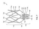
- FIG. 7shows a side view of a frame of the bronchial isolation device.
- FIG. 8shows a front view of the frame of FIG. 7 .
- FIG. 9shows the frame of FIG. 10 in a contracted state.
- FIG. 10shows another embodiment of the frame of the bronchial isolation device.
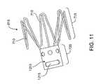
- FIG. 11shows another embodiment of the frame of the bronchial isolation device.
- FIG. 12shows another embodiment of a bronchial isolation device including a frame with dual retainer portions.
- FIG. 13shows an embodiment of the frame with cross struts, the frame in an expanded, annular state.
- FIG. 14shows another embodiment of the frame with retention prongs.
- FIG. 15shows a front view of another embodiment of the frame.
- FIG. 16shows a cross-sectional, side view of the frame of FIG. 16 along line 16 - 16 of FIG. 15 .
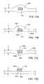
- FIGS. 17A-17Deach show a cross-sectional view of a portion of a frame strut and an embodiment of the membrane of the bronchial isolation device, the view along the line 17 - 17 of FIG. 13 .
- FIG. 18shows a step in the process of forming a membrane on the frame of the bronchial isolation device.
- FIG. 19shows another step in the process of forming a membrane on the frame of the bronchial isolation device.
- FIG. 20shows another step in the process of forming a membrane on the frame of the bronchial isolation device.
- FIG. 21shows an embodiment of the flow control device having an untrimmed membrane edge.
- FIG. 22shows an embodiment of the flow control device having a reinforced membrane edge.
- FIG. 23shows a perspective view of a duckbill valve member of the bronchial isolation device.
- FIG. 24shows a top view of the duckbill valve member of FIG. 23 .
- FIG. 25shows a cross-sectional, side view of the duckbill valve member of FIG. 23 .
- FIG. 26shows a perspective view of another embodiment of a duckbill valve member with a straight leading edge.
- FIG. 27shows a top view of the duckbill valve member of FIG. 26 .
- FIG. 28Ashows a perspective view of an embodiment of a one-way duckbill valve that provides a controlled flow in a reverse direction.
- FIG. 28Bshows an enlarged, perspective view of a mouth region of the valve of FIG. 28A .
- FIG. 29shows a cross-sectional view of the bronchial isolation device employing the frame of FIGS. 15 and 16 .
- FIG. 30shows a bronchial isolation device deployed in a bronchial passageway.
- FIG. 31shows a bronchial isolation device deployed in a bronchial passageway and partially embedded in a bronchial wall of the passageway.
- FIGS. 32A-32Ceach show an enlarged view of the portion of the flow control device that forms a seal with the bronchial wall.
- FIG. 33shows a bronchoscope deployed within a bronchial tree of a patient for delivering a bronchial isolation device into a bronchial passageway.
- bronchial isolation devices 610that can be used to isolate a diseased region of the lung in order to modify the air flow to the lung region or to achieve volume reduction or collapse of the lung region.
- One or more of the bronchial isolation devices 610are implanted in bronchial passageways that feed fluid to a targeted region of the lung.
- the bronchial isolation devices 610block or regulate fluid flow to the diseased lung region through one or more bronchial passageways that feed air to the targeted lung region.
- the bronchial isolation of the targeted lung regionis accomplished by implanting a bronchial isolation device 610 into a bronchial passageway 15 that feeds air to a targeted lung region 20 .
- the bronchial isolation device 610regulates airflow through the bronchial passageway 15 in which the bronchial isolation device 10 is implanted.
- Various embodiments of bronchial isolation devicesare described herein.
- lung regionrefers to a defined division or portion of a lung.
- lung regionsare described herein with reference to human lungs, wherein some exemplary lung regions include lung lobes and lung segments.
- the term “lung region” as used hereincan refer, for example, to a lung lobe or a lung segment. Such nomenclature conforms to nomenclature for portions of the lungs that are known to those skilled in the art.
- lung regiondoes not necessarily refer to a lung lobe or a lung segment, but can refer to some other defined division or portion of a human or non-human lung.
- FIG. 2shows an anterior view of a pair of human lungs 110 , 115 and a bronchial tree 120 that provides a fluid pathway into and out of the lungs 110 , 115 from a trachea 125 , as will be known to those skilled in the art.
- the term “fluid”can refer to a gas, a liquid, or a combination of gas(es) and liquid(s).
- FIG. 2shows only a portion of the bronchial tree 120 , which is described in more detail below with reference to FIG. 5 .
- FIG. 2shows a path 102 that travels through the trachea 125 and through a bronchial passageway into a location in the right lung 110 .
- proximal directionrefers to the direction along such a path 102 that points toward the patient's mouth or nose and away from the patient's lungs.
- the proximal directionis generally the same as the expiration direction when the patient breathes.
- the arrow 104 in FIG. 2points in the proximal or expiratory direction.
- the term “distal direction”refers to the direction along such a path 102 that points toward the patient's lung and away from the mouth or nose.
- the distal directionis generally the same as the inhalation or inspiratory direction when the patient breathes.
- the arrow 106 in FIG. 2points in the distal or inhalation direction.
- the lungsinclude a right lung 110 and a left lung 115 .
- the right lung 110includes lung regions comprised of three lobes, including a right upper lobe 130 , a right middle lobe 135 , and a right lower lobe 140 .
- the lobes 130 , 135 , 140are separated by two interlobar fissures, including a right oblique fissure 126 and a right transverse fissure 128 .
- the right oblique fissure 126separates the right lower lobe 140 from the right upper lobe 130 and from the right middle lobe 135 .
- the right transverse fissure 128separates the right upper lobe 130 from the right middle lobe 135 .
- the left lung 115includes lung regions comprised of two lobes, including the left upper lobe 150 and the left lower lobe 155 .
- An interlobar fissure comprised of a left oblique fissure 145 of the left lung 115separates the left upper lobe 150 from the left lower lobe 155 .
- the lobes 130 , 135 , 140 , 150 , 155are directly supplied air via respective lobar bronchi, as described in detail below.
- FIG. 3is a lateral view of the right lung 110 .
- the right lung 110is subdivided into lung regions comprised of a plurality of bronchopulmonary segments. Each bronchopulmonary segment is directly supplied air by a corresponding segmental tertiary bronchus, as described below.
- the bronchopulmonary segments of the right lung 110include a right apical segment 210 , a right posterior segment 220 , and a right anterior segment 230 , all of which are disposed in the right upper lobe 130 .
- the right lung bronchopulmonary segmentsfurther include a right lateral segment 240 and a right medial segment 250 , which are disposed in the right middle lobe 135 .
- the right lower lobe 140includes bronchopulmonary segments comprised of a right superior segment 260 , a right medial basal segment (which cannot be seen from the lateral view and is not shown in FIG. 3 ), a right anterior basal segment 280 , a right lateral basal segment 290 , and a right posterior basal segment 295 .
- FIG. 4shows a lateral view of the left lung 115 , which is subdivided into lung regions comprised of a plurality of bronchopulmonary segments.
- the bronchopulmonary segmentsinclude a left apical segment 310 , a left posterior segment 320 , a left anterior segment 330 , a left superior segment 340 , and a left inferior segment 350 , which are disposed in the left lung upper lobe 150 .
- the lower lobe 155 of the left lung 115includes bronchopulmonary segments comprised of a left superior segment 360 , a left medial basal segment (which cannot be seen from the lateral view and is not shown in FIG. 4 ), a left anterior basal segment 380 , a left lateral basal segment 390 , and a left posterior basal segment 395 .
- FIG. 5shows an anterior view of the trachea 125 and a portion of the bronchial tree 120 , which includes a network of bronchial passageways, as described below.
- the trachea 125divides at a lower end into two bronchial passageways comprised of primary bronchi, including a right primary bronchus 410 that provides direct air flow to the right lung 110 , and a left primary bronchus 415 that provides direct air flow to the left lung 115 .
- Each primary bronchus 410 , 415divides into a next generation of bronchial passageways comprised of a plurality of lobar bronchi.
- the right primary bronchus 410divides into a right upper lobar bronchus 417 , a right middle lobar bronchus 420 , and a right lower lobar bronchus 422 .
- the left primary bronchus 415divides into a left upper lobar bronchus 425 and a left lower lobar bronchus 430 .
- Each lobar bronchus, 417 , 420 , 422 , 425 , 430directly feeds fluid to a respective lung lobe, as indicated by the respective names of the lobar bronchi.
- the lobar bronchieach divide into yet another generation of bronchial passageways comprised of segmental bronchi, which provide air flow to the bronchopulmonary segments discussed above.
- a bronchial passagewaydefines an internal lumen through which fluid can flow to and from a lung or lung region.
- the diameter of the internal lumen for a specific bronchial passagewaycan vary based on the bronchial passageway's location in the bronchial tree (such as whether the bronchial passageway is a lobar bronchus or a segmental bronchus) and can also vary from patient to patient.
- the internal diameter of a bronchial passagewayis generally in the range of 3 millimeters (mm) to 10 mm, although the internal diameter of a bronchial passageway can be outside of this range.
- a bronchial passagewaycan have an internal diameter of well below 1 mm at locations deep within the lung.
- FIG. 6shows a perspective view of a bronchial isolation device 610 that includes a frame 615 , a valve member 620 mounted in the frame 615 , and a membrane 625 .
- the bronchial isolation device 610can be positioned within a bronchial passageway to regulate fluid flow through the bronchial passageway.
- FIG. 7shows a side, perspective view of a first embodiment of the frame 615 , which includes a retainer portion 715 and an integrally-connected valve protector portion 720 .
- the frame 615is comprised of a plurality of interconnected struts 710 that collectively form the outer periphery of the bronchial isolation device 610 .
- at least some of the struts 710are collectively arranged in an annular configuration such that the shape of the frame 615 approximates the internal shape of a bronchial passageway.
- the struts 710are arranged so as to form a plurality of diamond-shaped cells 712 .
- the cellsare referred to generally using the reference numeral 712 .
- Cells within the retainer portion 715are referred to as “retainer cells 712 a ” and cells within the valve protector portion 720 are referred to as “valve protector cells 712 b .”
- the cells 712can vary in size and shape.
- the retainer cells 712 aare longer and wider in size than the valve protector cells 712 b .
- the size, shape and quantity of the struts 710 and the cells 712can vary.
- the struts 710can be arranged in a z-pattern or a “zig-zag” pattern.
- the retainer portion 715 of the frame 615has a diameter that is larger than the diameter of the valve protector portion 720 .
- the diameter of the retainer portion 715is sufficiently large to cause the retainer portion 715 to press against and anchor to the walls of the bronchial passageway to secure the bronchial isolation device 610 in a fixed location relative to the bronchial passageway.
- Each retainer cell 712 a of the frame 615may be shaped to have a curved, distal edge 725 and a curved, proximal edge 730 that both assist in anchoring the retainer portion 715 to the bronchial passageway, as described more fully below.
- Each cell 712 ais attached to an adjacent cell 712 b at a cell junction 735 .
- the valve protector portion 720has valve protector cells 712 b , which are smaller than the retainer cells 712 a of the retainer portion 715 in order to compensate for the smaller diameter of the valve protector portion 720 .
- Each valve protector cell 712 bmay have a curved, distal edge 735 and a curved, proximal edge 740 .
- the size and shape of the valve protector cells 712 b and the retainer cells 712 acan vary.
- the valve protector portion 720at least partially surrounds the valve member 620 to maintain a default shape of the valve member, as described more fully below.
- the valve protector portion 720can be rigid or flexible and it can be configured to collapse and expand.
- a plurality of linking struts 745connect the valve protector portion 720 to the retainer portion 715 of the frame 615 .
- at least one linking strut 745connects each retainer cell 712 a to each valve protector cell 712 b .
- each linking strut 745has a first end that connects to the curved, proximal edge 730 of a respective retainer cell 712 a .
- Each linking strut 745also has a second end that connects to a cell junction 735 between two valve protector cells 712 b or to a distal point of a zig-zag strut of the valve protector portion 720 .
- the linking struts 745extend in a longitudinal direction from the valve protector portion 720 to the retainer portion 715 .
- the linking struts 745can be manufactured to be stiff or flexible.
- the linking struts 745curve radially outward from the valve protector portion 715 to provide the frame 615 with a smoothly-shaped transition between the retainer portion 715 and the valve protector portion 720 so as to eliminate sharp edges. As can be seen in FIG. 7 , the linking struts 745 have a smooth, curved contour without sharp edges to lessen the likelihood of the frame 615 digging into the bronchial wall during removal of the bronchial isolation device 610 .
- connection between the curved, proximal edges 730 of the retainer cells 712 a and the first end of each linking strut 745eliminates the proximal edges 730 of the retainer cells 712 a from hanging in midair, which reduces the likelihood of the proximal edges 730 digging into the bronchial wall during removal.
- the linking struts 745also provide a structural connection between the retainer portion 715 of the frame 615 and the distal edges 730 of the retainer cells 712 a .
- the frame 615can transition between a contracted state and an expanded state. In the contracted state, the frame 615 has a diameter that is smaller than the diameter of the frame 615 in the expanded state.
- FIG. 9shows a perspective view of another embodiment of a frame 615 in the contracted state, wherein the struts 710 form a series of undulating loops that can be, for example, in a zig-zag pattern. The struts 710 are arranged close to one another so that the cells 712 are constricted and the frame 615 has a reduced diameter.
- the frame 615 in FIG. 9is a different embodiment than the frame of FIG. 7 .
- the frame 615 in FIG. 9is the frame of FIG. 10 in a contracted state.
- the struts 710can form at least two connected rows of undulating loops.
- the connected rows of undulating loopstransition to diamond-shaped cells in the expanded state. It should be appreciated that the pattern of the struts can vary in both the contracted and expanded states.
- the retainer portion 715 of the frame 615radially expands to a larger diameter than the valve protector portion 720 so that the frame takes on the shape shown in FIG. 7 .
- the bronchial isolation device 610has a compressed profile that facilitates insertion of the bronchial isolation device 610 into a delivery device, such as a bronchoscope, and also facilitates insertion into a bronchial passageway.
- the frame 615is manufactured of a malleable material.
- the frame 615can be manually expanded to the anchoring state, such as by inserting an inflatable balloon inside the frame 615 once the bronchial isolation device 610 is implanted in the bronchial passageway, and then inflating the balloon to expand the frame beyond the material's yield point into an interfering engagement with the wall of the bronchial passageway.
- the insertion statecan be achieved through a preconstraint of the frame 615 within the elastic range of the frame material. Once positioned in the bronchial passageway, the frame 615 can be released from constraint so that spring resilience causes it to expand into an anchoring state. Constraining tubes or other mechanisms may achieve the initial insertion state.
- the transition temperature of the frame 615could be at a predetermined temperature, such as below body temperature. Under such a circumstance, a frame 615 that is at a temperature below the transition temperature can be deformed into a shape that is suitable for insertion, and will stay in this unrecovered state until the temperature is brought above the transition temperature. The unrecovered state of the frame 615 would be in an insertion position with the frame 615 having a smaller diameter. Upon recovery of the frame material, the frame 615 would expand, such as when the frame achieves a predetermined temperature within the bronchial passageway.
- the frame 615can be manufactured of a variety of bio-compatible materials.
- the frame 615is manufactured of a superelastic material, such as Nitinol, that is heat-treated to attain the shape shown in FIG. 7 .
- the entire frame 615is manufactured out of a single piece of tubing made out of Nitinol or some other material.
- FIG. 9shows an isometric view of a tubular piece of material that has been cut into a pattern that forms the desired strut pattern. Once the material has been cut, such as through laser-cutting or chemical etching, the material is expanded and optionally heat treated so that it attains the shape shown in FIG. 10 .
- the framemay be manufactured from a flat piece of material that is cut into a pattern that forms the desired strut pattern, rolled into an annular configuration and then the mating edges are welded, bonded or otherwise joined. The material, as before, is then expanded and optionally heat treated so that it attains the shape shown in FIG. 10 .
- the frame 615can be manufactured of other materials, such as plastic or stainless steel
- FIG. 10shows a perspective view of another embodiment of the frame 615 wherein the linking struts 745 are connected to different locations on the retainer portion 715 and valve protector portion 720 of the frame.
- the first end of the linking strut 745is connected to the retainer portion 715 at the cell junction 735 between a pair of retainer cells 712 a .
- the second end of the linking strut 745is connected to a cell junction 735 between a pair of valve protector cells 712 b .
- the curved, proximal edges 730 of the retainer cells 712 aare cantilevered in that they are not connected to or supported by linking struts 745 .
- FIG. 11shows yet another embodiment of the frame 615 .
- valve protector portion 720 of the frame 615comprises a tube 1210 formed of a solid wall rather than a plurality of struts.
- the tube 1210can include at least one removal window 1215 that can be grasped by a removal device (such as a set of jaws) during removal of the bronchial isolation device 610 from a bronchial passageway.
- the retainer portion 710comprises a plurality of struts 710 that are shown arranged in a zig-zag pattern, although the struts 710 can also form cells, as in the previous embodiments, or can be in other patterns.
- the valve protector portion 720 comprised of the tube 1210does not undergo any expansion or contraction, but rather retains its size. However, the retainer portion 715 can expand and contract as in the previous embodiments.
- FIG. 12shows another embodiment of the frame 615 (including the membrane 625 ) that includes two retainer portions including a proximal retainer portion 715 a and a distal retainer portion 715 b .
- a central valve protector portion 720is disposed in-between the proximal retainer portion 715 a and the distal retainer portion 715 b and connected thereto by linking struts 745 .
- the retainer portions 715 a,bhave larger diameters than the valve protector portion 720 so that the frame 615 has an hourglass-like shape. It should be appreciated that the diameter of the proximal retainer portion 715 a is not necessarily equal to the diameter of the distal retainer portion 715 b.
- the dual retainer portions 715 a , 715 bcan provide an increase in stability when the bronchial isolation device 610 is mounted in a bronchial passageway, as both retainer portions 715 a , 715 b provide independent anchors to the bronchial wall. Both retainer portions 715 a , 715 b also provide seals against the bronchial wall in which the bronchial isolation device is mounted. Thus, if the anchor or seal in one of the retainer portions weakens or fails, the other anchor portion 715 a or 715 b can compensate for the weakened or failed seal.
- bronchial isolation deviceIt is important to prevent the bronchial isolation device from migrating in either the proximal or the distal direction after implantation in the bronchial passageway. It has been determined that migration in the proximal (i.e., exhalation) direction can occur when the patient coughs, resulting in pressure buildup behind the bronchial isolation device. This can lead to migration or expulsion of the device from the bronchial passageway.
- One mitigating factor that can reduce the likelihood of this occurringis that the bronchial passageways are constricted by the pressure of the cough, and this can cause the passageway to tend to grip the device more firmly in place.
- exhalationis inherently difficult for patients with emphysema, and has the effect of reducing the pressure that can build up behind the device during exhalation.
- the exhalation flow produced by coughing or breathingwill preferentially flow through the valve, and will thus reduce the pressure that can build up behind the device.
- Migration in the distal (i.e., inhalation) directioncan occur when the patient takes a deep inhalation breath, which can result in the device being “sucked” deeper into the lung. This effect is exacerbated by the fact that the bronchial lumens expand when air is inhaled, and this can lead to a less secure retention of the device in the airway.
- FIGS. 13-16show embodiments of the frame 615 that include features that prevent or limit migration of the device in the proximal or distal direction once the device is implanted in a bronchial passageway.
- the frame 615includes retention prongs comprised of cross struts that resist migration of the bronchial isolation device in a bronchial passageway, such as by limiting the depth that the cell portions of the frame can penetrate into a bronchial wall in which the bronchial isolation device 610 is located.
- FIG. 13shows the frame 615 in an expanded, annular state, wherein the frame includes at least one distal cross strut 1410 and at least one proximal cross strut 1415 .
- the cross struts 1410 , 1415comprise additional struts or projections that have v-shape in the expanded state and extend outward between the struts of the frame 615 .
- the cross struts 1410 , 1415can be loop shaped in the contracted state.
- the cross struts 1410 , 1415extend outward from the cells 712 at connection locations 1420 , which serve as stopping points that limit the cells 712 from penetrating into a bronchial wall beyond a predetermined distance, as described in more detail below.
- the cross struts 1410 , 1415also form additional cells 1425 that can be engaged with the membrane 625 to provide additional sealing capability between the frame 615 and the bronchial wall. It should be appreciated that the cross struts 1410 , 1415 can be positioned at various locations on the frame beside that which is shown in FIG. 13 .
- FIG. 14shows another embodiment of the frame 615 with retention prongs 1610 that project radially-outward from the struts 710 in the expanded state.
- the prongs 1610are bent so that they protrude radially-outward from the radial periphery of the retainer portion of the frame 615 .
- the prongs 1610can at least partially sink in the bronchial wall tissue and prevent migration of the device in the distal direction.
- the retention prongs 1610limit migration in the distal direction by fixing the frame 615 to the bronchial wall and thus preventing the cells 712 from penetrating the bronchial wall tissue.
- FIG. 15shows a front view of the frame 615
- FIG. 16shows a cross-sectional view of the frame 615
- the valve member 620is shown in FIG. 16 mounted within the valve protector portion 720 .
- FIG. 16does not show the membrane 625 for clarity of illustration, although it should be appreciated that the membrane 625 would be attached to the frame 615 and the valve member 620 and would thereby secure the valve member 620 to the frame 615 .
- the frame 615includes distal cross struts 1410 that form distal cells 1425 that can be smaller than the retainer cells 712 a .
- the cells 1425can move and flex independently of the retainer cells 712 a that form the remainder of the retainer section 715 of the frame 615 . This allows different portions of the retainer sections to independently conform to the shape of a bronchial wall.
- FIG. 17Ashows a cross-sectional view of a portion of the membrane 625 and a strut 710 , cut along the line 17 - 17 of FIG. 13 .
- the membrane 625can fully encapsulate the struts 710 of the frame 615 so that the membrane 625 is integrally attached to the frame 615 .
- the encapsulation of the membrane 625 over the struts 710can be accomplished by using a dipping manufacturing process described below.
- the membrane 625can also be connected to the valve member 620 .
- the membrane 625extends in a web-like manner between the struts 710 within the spaces of the cells 712 of the frame 615 .
- the membrane 625can be stretched in tension across the cells, although this is not necessary.
- the membranehas a thickness T.
- the membrane 625generally bulges outwardly from the struts 710 in the region where the membrane 625 surrounds the struts.
- the thickness Tis not substantially larger than the diameter or thickness of the struts 710 . In this manner, the membrane 625 does not substantially contribute to or increase the diameter of the frame 615 .
- the membrane 625can be disposed over the entire frame 615 , including both the retainer portion 715 and the valve protector portion 720 , or the membrane can be disposed only over a portion of the frame, such as the enlarged-diameter retainer portion 715 . It should be appreciated that the thickness T of the membrane can vary relative to the diameter of the struts 710 and that the thickness T need not be uniform across the entire membrane.
- FIG. 17Bshows another embodiment of the configuration of the membrane 625 relative to the struts 710 .
- the membrane 710does not entirely encapsulate the strut 710 but rather leaves a portion of the strut 710 uncovered or exposed.
- the membrane 710covers a radially-outward portion 1602 and sides of the strut 710 and does not cover a radially-inward portion 1604 of the struts 710 .
- An inner surface 1606 of the membrane 625is positioned substantially flush with the radially-inward portion 1604 of the strut 710 , thereby leaving the radially-inward portion 1604 exposed.
- FIG. 17Cshows another embodiment of the configuration of the membrane 625 relative to the strut 710 wherein the membrane 625 does not entirely encapsulate the strut 710 .
- the membranecovers the radially-inward portion 1604 but does not cover the radially-outward portion 1602 of the strut 710 .
- An outer surface 1608 of the membrane 625is positioned substantially flush with the radially-outward portion 1602 of the strut 710 , thereby leaving the radially-outward portion 1602 exposed.
- FIG. 17Dshows yet another embodiment of the configuration of the membrane 625 relative to the strut 710 .
- the membrane 625is mounted on one side of the strut 710 and does not encapsulate or surround the strut 710 .
- FIG. 17Dshows the membrane 625 mounted on the radially-inward portion 1604 of the strut 710 with the outer surface 1608 of the membrane juxtaposed with the radially-inward portion 1604 .
- the membrane 625can also be mounted on the radially-outward portion 1602 .
- the membrane 625can be mounted on the struts 710 in other manners and that the membrane 625 can encapsulate other portions of the struts and leave various portions of the struts 710 uncovered or exposed.
- the membrane 625is disposed over the entire retainer portion of the frame 615 such that the retainer portion can expand and contract without causing the membrane 625 to wrinkle against the bronchial wall when disposed in a bronchial passageway.
- the membrane 625can be thin and elastic so that the membrane 625 can expand along with the frame 615 without inhibiting the frame from exerting a sufficient radial force to grip the bronchial wall.
- the membrane 625does not inhibit the frame 615 from expanding or contracting, but rather expands and contracts according to any expansion or contraction of the frame 615 .
- the membrane 625is desirably attached to the valve member 620 in a leak-free manner. That is, when the bronchial isolation device 610 is positioned in a bronchial passageway, fluid is prevented from flowing in-between the membrane 625 and the valve member, but must rather flow through a fluid-flow opening in the valve member 620 .
- the membrane 625provides a fluid pathway into an entry mouth of the valve member that directs fluid in a bronchial passageway into the valve member, as described more fully below. It is not necessary that the membrane 625 completely cover the self-expanding valve protector section of the frame or that the membrane 625 completely cover the valve member 620 .
- the membrane 625is firmly attached to the self-expanding, retainer portion 715 of the frame 615 .
- the self-expanding retainer portion 715radially expands to sealingly anchor against the bronchial passageway wall.
- the sealcan be either between the membrane 625 and the bronchial wall or the frame 615 and the bronchial wall, as described more fully below.
- the bronchial isolation device 610seals inside the bronchial passageway, and flow of fluid around the bronchial isolation device 610 is prevented in a desired direction, such as the inhalation direction or in the exhalation direction.
- the bronchial isolation device 610also prevents flow around the device in the exhalation direction, and the only flow that is allowed is through the valve member 620 in the exhalation direction.
- the self-expanding retainer portion 715 of the frame 615can be configured to allow fluid flowing in the exhalation direction to flow between the frame and the bronchial lumen wall as well as through the one-way valve, yet still prevent flow in the inhalation direction (either through the one-way valve or between the frame and the bronchial lumen wall).
- the flexible membrane 625can be thin so that it provides a relatively small amount of material that must be compressed when the bronchial isolation device 610 is in the compressed state.
- the membrane 625is contoured so as to increase the tendency of the membrane 625 to deform in a desired manner when the flow control device 610 is compressed.
- the thickness of the membrane 625can vary. In one embodiment, the membrane 625 has a thickness in the range of about 0.0005 inch to about 0.005 inch, although other thickness outside this range are possible. In one embodiment, the membrane 625 has a thickness in the range of about 0.001 inch to about 0.010 inch In one embodiment, the thickness of the membrane is 0.003 inch.
- the flexible membrane 625is formed of a biocompatible, flexible material, such as, for example, silicone, urethane, or a urethane/silicone composite. It should be appreciated that the membrane can be manufactured of other materials.
- the thin membrane 625can be manufactured according to a variety of processes.
- the membrane 625is manufactured by dipping a frame 615 into a dispersion 1810 of material used to manufacture the membrane 625 .
- the dispersion 1810is located within a container 1815 .
- the frame 615is first expanded, such as to the maximum possible diameter. This may be accomplished, for example, by mounting the frame 615 onto a mounting tool, such as a mandrel 1820 that is sized to receive the frame 615 .
- the frame 615is then dipped into the dispersion 1810 , such as in a dispersion of silicone, polyurethane or other polymer.
- the dispersion 1810is generated by mixing platinum cure silicone (uncured) with xylene.
- Another exemplary dispersion 1810comprises polyurethane dissolved in a solvent such as THF (tetrahydrofuran) or DMAC (dimethyl acetamide).
- the material of the dispersionadheres to the frame 615 .
- the adhesion of a polymeric dispersion to a Nitinol framecan be enhanced with a primer such as a naphtha solution, which is especially useful for silicone membranes.
- the frame 615is removed from the dispersion so that a portion of the dispersion adheres to the frame 615 .
- the dispersionis then allowed to cure and form the membrane 625 .
- the thickness of the membrane 625can be controlled by adjusting the percent solids of the dispersion and the dip rate, or through the use of a dipping mandrel, such as the mandrel 1810 shown in FIG. 18 .
- the dipped frame 615is rotated during the cure process about an axis that is either in a vertical orientation, a horizontal orientation, or both. The rotation of the frame 615 uniformly coats the dispersion about the frame 615 . A variety of membrane thicknesses can be achieved using this process.
- One specific method of applying the dispersion 1810 to the frame 615is to dip the frame 615 into the dispersion 1810 (such as silicone), rotate the frame 615 to a horizontal position, and spin the frame 615 about a horizontal axis 1915 to evenly distribute the dispersion 1810 about the frame 615 , as shown in FIG. 19 .
- the frame 615is rotated to a vertical position that is upside down relative to the original dipped position, and spun about a vertical axis 2010 to continue to evenly distribute the dispersion, as shown in FIG. 20 .
- the siliconecan then be cured in an oven.
- One curing methodincludes a two stage cure.
- the siliconeis cured at a first temperature for a first amount of time, such as at 140° F. for 10 minutes.
- a second temperature for a second amountsuch as at 325° F. for 10 minutes.
- the membrane 625can have a contoured shape that increases the tendency of the membrane to deform in a desired manner when the flow control device is compressed.
- the contours on the membrane 625can be created by dipping a stent that has a number of closed cells or perimeters, such as the cells 712 .
- the dispersionfills the cells and creates a surface tension within the cells, which creates a dispersion membrane across each closed perimeter so that the membrane solidifies upon curing.
- the membrane contourscan be altered by conducting the dipping process with the stent placed over a formed tool or mandrel 1820 .
- the mandrel 1820is manufactured of a material that does not adhere to the dispersion, such as PFA or some other fluoropolymer, in order to eliminate or reduce adhesion of the membrane 625 to the mandrel 1820 .
- the shape of the membrane 625can be altered when the frame 615 is compressed for delivery.
- the mandrel 1820can be contoured to create concave surfaces on the membrane, wherein the concave surfaces will pleat inward during compression of the frame 615 . This protects the membrane during compression, loading, and deployment of the bronchial isolation device.
- the membrane 625does not extend distally or proximally past the frame 615 . That is, the membrane 625 is trimmed so that its distal edge follows the contours of the distal-most struts 710 .
- the membrane 625extends distally past the struts 710 such that the membrane 625 has an untrimmed, distal edge 2102 .
- the distal edge 2102is folded over and bonded to itself to form a flap. It can be folded over either inside or outside of the membrane 625 .
- the folded-over flapprovides a thicker distal edge 2102 to reinforce the structural integrity of the distal edge 2102 .
- the distal edge 2102can be structurally-reinforced by dipping the distal edge 2102 into a dispersion of the membrane material or by applying a section of the material to the distal edge 2102 with a syringe, and then curing the membrane 625 to form a reinforcing bead on the distal edge 2102 .
- the valve member 620is disposed within the valve protection portion 720 of the frame 615 .
- the valve member 620can be configured to either permit fluid flow in two directions (i.e., proximal and distal directions), permit fluid flow in only one direction (proximal or distal direction), completely restrict fluid flow in any direction through the bronchial isolation device 610 , or any combination of the above.
- the valve member 620can be configured such that when fluid flow is permitted, it is only permitted above a certain pressure, referred to as the cracking pressure.
- the valve member 620is desirably formed of an elastic, biocompatible material, such as silicone, although other materials can be used.
- valve member 620comprises a one-way valve, it desirably has the following characteristics: low cracking pressure, high flow in the forward direction, rapid closure upon flow reversal, and complete sealing in the reverse direction, as discussed below.
- the cracking pressure in the exhalation directionis in the range of 0 to 10 inches of water. In another embodiment, the cracking pressure is in the range of 0 to 5 inches of water. In another embodiment, the cracking pressure is in the range of 0 to 2 inch of water. Given the 100% humidity conditions that exist in the lungs, these cracking pressures can be measured under similar or wet conditions in order to simulate the conditions of the lungs.
- the pressure differential across the valve at a flow of 50 ml/min in the exhalation directionis in the range of 0 to 4 inches of water.
- the pressure differential across the valve at a flow of 50 ml/min in the exhalation directionis in the range of 0 to 2 inch of water.
- the pressure differential across the valve at a flow of 50 ml/min in the exhalation directionis in the range of 0 to 1 inches of water.
- the responsiveness of the valveis a measure of how quickly the valve closes once flow through the valve in the exhalation direction is stopped. For example, a high-performing valve would close instantly when the valve encounters a reverse-direction flow and not allow any flow in the reverse direction back through the valve.
- a flow of 120 ml/minis sent in the exhalation direction of the valve, and then reversed to flow in the inhalation direction, the valve closes and seal completely in less than 4 seconds in one embodiment, in less than 2 seconds in another embodiment, and in less than 1 second in another embodiment.
- valve bronchial isolation devicesit is desirable for implanted one-way valve bronchial isolation devices to seal completely in the inhalation direction at all times after deployment in a bronchial passageway under all conditions.
- the valvedesirably stays sealed regardless of the orientation of the patient's body, regardless of the rotational orientation of the valve in the bronchial lumen, regardless of whether or not the implanted device is being compressed by external compression of the bronchial lumen, regardless of whether or not there is mucus present on the valve seal surfaces, etc.
- the valveshould remain sealed even if there is little or no pressure differential across the valve
- the valve member 620comprises a duckbill valve that permits flow in one direction and prevents or restricts flow in a second direction.
- FIGS. 23-25show an embodiment of a valve member 620 comprised of a duckbill valve 2310 that can be used in the bronchial isolation device 610 .
- the duckbill valve 2310includes a tubular base 2315 that has an outer diameter that fits within the annular valve protector portion 720 of the frame 615 .
- the duckbill valve 2310includes a pair of opposed, inclined walls 2320 having ends that meet at lips 2325 . The lips 2325 meet at two opposed corners.
- the walls 2320can move with respect to one another so as to separate at the lips 2325 and form an opening through which fluid can travel.
- a first directionrepresented by the arrow 2330 in FIG. 23
- the walls 2320separate from one another to form the opening.
- a second directionrepresented by the arrow 2335 in FIG. 23
- the walls 2320remain closed and prevent fluid from flowing through the duckbill valve 2310 .
- the valve protector portion 720 of the frame 615provides structural support to the valve member 620 and serves to prevent the valve member 620 from being deformed to the extent that the performance of the valve member 620 is adversely affected.
- a bronchial passagewaycan constrict or otherwise change shape during inhalation, exhalation, or cough.
- the valve protector portion 720substantially shields the valve member 620 from excessive deformation when the bronchial passageway changes shape.
- the valve member 620can optionally include a reinforcement member 2202 comprised of a curved or looped wire that extends between the two corners of the lips and around the duckbill valve 2310 or other type of valve. For clarity of illustration, the reinforcement member is only shown in FIG. 24 .
- the curved wireis rigid so as to provide structural protection to the valve 2310 , such as to maintain the distance between the corners of the lips, in the event that the valve 2310 is exposed to forces that might deform the valve 2310 .
- the reinforcement member 2202may be used in combination with the valve protector portion 720 of the frame, of may be used as a substitute for the valve protector portion 720 .
- the walls 2320have an outwardly-domed outer surface 2342 and as a leading edge 1910 that forms an outward curve.
- the curved-shape of the leading edge 1910provides a longer lips 2325 than the lip for a straight leading edge, such as the straight leading edge 2502 of the duckbill valve 2504 shown in FIGS. 26 and 27 .
- the resultis that for a given valve size, the flow rate at a given differential pressure across the lips is higher for a curved leading edge valve than for a straight leading edge valve.
- Table 1lists the pressure drop across two duckbill valves, including a duckbill valve with a curved leading edge (i.e., a curved mouth) and a diameter of about 0.128 inches and a duckbill valve with a straight leading edge (i.e., a straight mouth) and a diameter of about 0.116 inches. As shown in Table 1, even though the curved-mouth valve has a smaller diameter, the pressure drop across the curved-mouth valve is lower than the straight mouth valve at both 50 ml/min and 500 ml/min.
- the curved-mouth duckbill valveprovides a higher flow rate than the straight-mouthed duckbill valve, which makes the curved mouth duckbill valve particularly well suited for use in a one-way valve bronchial isolation device.
- the cracking pressure of a duckbill valvecan be altered by changing the angle between the faces of the two lips of the valves.
- the cracking pressurewill be reduced if this angle is reduced, and the cracking pressure will be increased if this angle is increased.
- the angleis reduced, the length of the valve increases, and this should be taken into account if a very short valve is desired.
- FIGS. 28A and 28Bshows an embodiment of a one-way duckbill valve 2702 that provides a controlled flow in a reverse direction.
- the valve 2702behaves as a one-way valve in the forward direction (represented by the arrow 2704 in FIG. 28A ) in that the valve 2702 allows free flow of fluid through the valve at or above the valve's cracking pressure.
- the valve 2702also allows a small, controlled rate of flow in the reverse direction (represented by the arrow 2706 in FIG. 28A ).
- the duckbill valve 2702includes a small flow channel 2708 that extends through the lips of the valve, as best shown in the enlarged view of FIG. 28B .
- the flow channel 2708allows fluid to flow in the reverse direction through the lips.
- the rate of flowis a function of the diameter and length of the flow channel 2708 .
- valve member 620can comprise valve types other than a duckbill valve.
- the one-way duckbill valvecould be replaced with another type of one-way valve, such as a flap valve, a Heimlich valve, a tri-lobe duckbill valve or other multi-lobe valves, a diaphragm valve, a ball valve, etc.
- the one-way valvecan be replaced with a blocking element to prevent flow through the device in either direction, or a two-way valve to allow controlled flow in both directions, or one-way or two-way valves that are designed to allow the passage of a catheter to suction, inject therapeutic substances or otherwise treat the isolated lung region distal to the implanted bronchial isolation device.
- FIG. 29shows a cross-sectional view of the flow control device 610 employing the embodiment of the frame 615 shown in FIGS. 15 and 16 .
- the valve member 620is mounted within the valve protector portion 720 of the frame 615 .
- the membrane 625is attached to the valve member 620 at one or more locations to secure the valve member 620 to the frame 615 .
- the valve memberis positioned such that an entry mouth 2903 is located at a distal region of the valve protector portion 720 and an exit mouth 2905 is located at a proximal region.
- the valve protector portion 720at least partially surrounds the valve member 620 to maintain a default shape of the valve member 620 .
- valve protector portion 720protects the valve member 620 from deformation.
- the default shape of the valve member 620can be a closed configuration that prohibits fluid flow or the default shape can be some other default shape.
- the membrane 625is positioned in a web-like manner within the cells 712 .
- the membrane 625covers or is connected to at least a portion of the frame 615 .
- the membranecovers at least a portion of the retainer portion 715 and can also cover at least a portion of the valve protector portion 720 .
- the membrane 625can cover the entire retainer portion 715 or it can cover a portion of the retainer portion 715 .
- the membrane 625can cover the entire valve protector portion 720 or it can cover a portion of the valve protector portion 720 .
- the membrane 625defines a fluid pathway that is open at a distal end of the frame 615 and that leads into the entry mouth 2903 of the valve 620 .
- the general outer contour of the fluid pathwayis represented by a bold line 2907 in FIG. 29 .
- the membrane 625follows the outer contour of the frame 615 such that the fluid pathway is generally cylindrical in this portion of the frame 615 .
- the fluid pathwayit is not necessary that the fluid pathway be cylindrical as long as it leads into the entry mouth 2903 of the valve member 620 .
- the membranecover the entire bronchial isolation device 610 as long as the membrane forms the fluid pathway.
- the outer contour of the membrane 625slopes radially inward (as exhibited by the bold lines 2911 ) moving toward the entry mouth 2903 of the valve member 620 .
- the membrane 625forms a funnel-shaped fluid pathway that leads into the valve member 620 .
- the membrane 625also forms radially-extending fins 2914 between the outer membrane wall of the funnel-shaped fluid pathway and the linking struts 745 .
- FIG. 30shows a cross-sectional view of bronchial passageway 2910 having interior walls 2915 that define a lumen of the bronchial passageway 2910 .
- fluidscan travel to and from a region of the lung through the lumen of the bronchial passageway 2910 .
- the embodiment of the bronchial isolation device 610 of FIG. 29is shown positioned within the bronchial passageway 2910 .
- the bronchial isolation device 610is shown in FIG. 30 with the membrane 625 trimmed along the distal edge of the frame 615 .
- the frame 615When the bronchial isolation device 610 is positioned within the bronchial passageway 2910 , the frame 615 is in an expanded state so that it exerts a radial force against the interior walls 2915 , as represented by the arrows 2912 in FIG. 30 .
- the radial forcecauses the frame 615 to press against the bronchial wall 2915 with a pressure sufficient to retain the bronchial isolation device 610 in a fixed position relative to the bronchial passageway.
- the distal edges 725 of the retainer cells 712 aare positioned such that they lodge against the interior walls 2915 and inhibit the bronchial isolation device 610 from migrating in the distal direction 206 .
- the proximal edges 730 of the retainer cells 712 aare attached to the linking struts 745 .
- the linking struts 745provide a smooth transition between the retainer section and the valve protector section of the frame 615 .
- the linking struts 745also lessen any sharpness of the proximal edges 730 of the retainer cells 712 a and prevent the proximal edges 730 from penetrating into the bronchial wall 2915 if the bronchial isolation device 610 is pulled in the proximal direction during removal.
- the linking struts 745assist in radially constricting the retainer section of the frame 615 during removal of the bronchial isolation device 610 .
- the linking struts 745transfer the radial constriction to the retainer section of the frame 615 .
- the frame 615can optionally include one or more distal cross struts 1410 and one or more proximal cross struts 1415 .
- the cross struts 1410 , 1415function to limit the distance that the cells 712 can penetrate into the bronchial wall 2915 .
- FIG. 31shows the bronchial isolation device 610 after it has migrated in the distal direction 206 such that some of the distal edges 725 of the retainer cells 712 a have penetrated into the bronchial wall 2915 .
- the connection point 3010 between the distal cross strut 1410 and the cell 712 aprovides a stopping point that will prevent the retainer cell 712 a from penetrating any deeper beyond the connection point 3010 .
- the expanded frame 615presses against the bronchial wall 2915 so that the bronchial isolation device 610 sealingly engages the bronchial wall 2915 around the entire circumference of the bronchial isolation device 610 .
- the sealcan be formed between the frame 615 and the bronchial wall 2915 , between the membrane 625 and the bronchial wall 2915 , between both the membrane 625 /frame 615 and the bronchial wall 2915 , or any combination thereof.
- FIG. 32Ashows an enlarged view of the portion of the flow control device 610 that forms a seal with the bronchial wall 2915 .
- FIG. 32Ashows an enlarged view of the portion of the flow control device 610 that forms a seal with the bronchial wall 2915 .
- the membrane 625is positioned between a frame strut 710 and the bronchial wall 2915 such that the membrane 625 seals with the bronchial wall 2915 .
- the situation shown in FIG. 32Acorresponds to use of the frame/membrane configuration shown in FIGS. 17A , 17 B.
- both the membrane 625 and the frame strut 710seal with the bronchial wall 2915 .
- the situation shown in FIG. 32Bcorresponds to use of the frame/membrane configuration shown in FIG. 17C .
- the frame strut 710seals with the bronchial wall 2915 but the membrane 625 does not necessarily seal with or contact the bronchial wall 2915 .
- the situation shown in FIG. 32Ccorresponds to use of the frame/membrane configuration shown in FIG. 17D .
- the frame 615is sealed with the bronchial wall 2915 .
- the sealcan occur at any location along the frame 615 as long as the membrane 625 provides a fluid pathway between the location of the seal and the valve member 620 .
- the cross struts 1410create additional cells that permit the frame to flex at different locations along its length. In this manner, the struts that form the cells can form independent and redundant seals with the bronchial wall 2915 .
- the frame 615 and/or the membrane 625provide a seal that prevents fluid from flowing between the interior walls 2915 and the bronchial isolation device 610 .
- the membrane 625engages with the portion of the bronchial isolation device that is sealed to the bronchial wall 2915 such that the fluid pathway formed by the membrane directs fluid into the valve member 620 so that fluid must flow through the valve member 620 in order to flow from a proximal side 2730 of the bronchial isolation device 610 to a distal side 2735 or vice-versa.
- the sealing engagement between the bronchial isolation device 610 and the bronchial wall 2915prevents fluid from flowing around the periphery of the bronchial isolation device 610 , thereby forcing fluid flow to occur through the membrane path and into the valve member 620 .
- the membrane 625provides a fluid pathway into the valve member 620 . It is not necessary for the membrane 625 to cover the entire bronchial isolation device as long as the membrane 625 forms a pathway from the location of the seal to the entry mouth of the valve member 620 .
- bronchial isolation device 610can be modified to permit such limited flow.
- the bronchial isolation device 610can be deployed to a desired location in a bronchial passageway according to a variety of methods.
- the bronchial isolation deviceis coupled to the distal end of a delivery catheter, which is then inserted through the patient's mouth or nose, into the trachea, and to the location in the bronchial passageway.
- the bronchial isolation device 610is then uncoupled from the delivery catheter such that it is positioned at a desired location in the bronchial passageway.
- a delivery catheter 3102can be deployed using a bronchoscope 3104 , which in an exemplary embodiment has a steering mechanism 3106 , a shaft 3108 , a working channel entry port 3112 , and a visualization eyepiece 3115 .
- the bronchoscope 3104has been passed into a patient's trachea 125 and guided into the right primary bronchus 510 according to well-known methods.
- the delivery catheter 3102is then inserted into the bronchoscope through the working channel entry port 3112 and fed into the working channel so the distal end 3120 of the delivery catheter (and the attached bronchial isolation device 610 ) protrude out of the distal end of the bronchoscope.
- the bronchial isolation device 610is then released from the delivery catheter so that the frame 615 expands and anchors at a desired location, as shown in FIG. 1 .
Landscapes
- Health & Medical Sciences (AREA)
- Engineering & Computer Science (AREA)
- Biomedical Technology (AREA)
- Life Sciences & Earth Sciences (AREA)
- Animal Behavior & Ethology (AREA)
- Surgery (AREA)
- Veterinary Medicine (AREA)
- Public Health (AREA)
- General Health & Medical Sciences (AREA)
- Heart & Thoracic Surgery (AREA)
- Vascular Medicine (AREA)
- Cardiology (AREA)
- Transplantation (AREA)
- Oral & Maxillofacial Surgery (AREA)
- Reproductive Health (AREA)
- Nuclear Medicine, Radiotherapy & Molecular Imaging (AREA)
- Medical Informatics (AREA)
- Molecular Biology (AREA)
- Physics & Mathematics (AREA)
- Optics & Photonics (AREA)
- Prostheses (AREA)
Abstract
Description
Rapid Valve Closure when Flow is Reversed
| TABLE 1 |
| Curved vs. Straight Duckbill Valve Pressure Drop |
| Valve Diameter, | Pressure Drop Across Valve, in-H2O |
| Valve Type | inches | 50 ml/min | 500 ml/min |
| Straight Mouth | 0.128 | 0.5 | 2.8 |
| Curved Mouth | 0.116 | 0.4 | 2.4 |
Claims (55)
Priority Applications (2)
| Application Number | Priority Date | Filing Date | Title |
|---|---|---|---|
| US10/627,941US7798147B2 (en) | 2001-03-02 | 2003-07-25 | Bronchial flow control devices with membrane seal |
| US12/857,356US8251067B2 (en) | 2001-03-02 | 2010-08-16 | Bronchial flow control devices with membrane seal |
Applications Claiming Priority (6)
| Application Number | Priority Date | Filing Date | Title |
|---|---|---|---|
| US09/797,910US6694979B2 (en) | 2000-03-04 | 2001-03-02 | Methods and devices for use in performing pulmonary procedures |
| US39927302P | 2002-07-26 | 2002-07-26 | |
| US39917302P | 2002-07-29 | 2002-07-29 | |
| US10/270,792US6941950B2 (en) | 2001-10-11 | 2002-10-10 | Bronchial flow control devices and methods of use |
| US42990202P | 2002-11-27 | 2002-11-27 | |
| US10/627,941US7798147B2 (en) | 2001-03-02 | 2003-07-25 | Bronchial flow control devices with membrane seal |
Related Parent Applications (2)
| Application Number | Title | Priority Date | Filing Date |
|---|---|---|---|
| US09/797,910Continuation-In-PartUS6694979B2 (en) | 2000-03-04 | 2001-03-02 | Methods and devices for use in performing pulmonary procedures |
| US10/270,792Continuation-In-PartUS6941950B2 (en) | 2001-03-02 | 2002-10-10 | Bronchial flow control devices and methods of use |
Related Child Applications (1)
| Application Number | Title | Priority Date | Filing Date |
|---|---|---|---|
| US12/857,356ContinuationUS8251067B2 (en) | 2001-03-02 | 2010-08-16 | Bronchial flow control devices with membrane seal |
Publications (2)
| Publication Number | Publication Date |
|---|---|
| US20040055606A1 US20040055606A1 (en) | 2004-03-25 |
| US7798147B2true US7798147B2 (en) | 2010-09-21 |
Family
ID=31999753
Family Applications (1)
| Application Number | Title | Priority Date | Filing Date |
|---|---|---|---|
| US10/627,941Active2027-03-09US7798147B2 (en) | 2001-03-02 | 2003-07-25 | Bronchial flow control devices with membrane seal |
Country Status (1)
| Country | Link |
|---|---|
| US (1) | US7798147B2 (en) |
Cited By (10)
| Publication number | Priority date | Publication date | Assignee | Title |
|---|---|---|---|---|
| US20110054512A1 (en)* | 2008-04-03 | 2011-03-03 | William Cook Europe Aps | Occlusion device |
| US8251067B2 (en) | 2001-03-02 | 2012-08-28 | Pulmonx Corporation | Bronchial flow control devices with membrane seal |
| US8808194B2 (en) | 2010-07-01 | 2014-08-19 | Pulmonx Corporation | Methods and systems for endobronchial diagnostics |
| US9364168B2 (en) | 2010-07-01 | 2016-06-14 | Pulmonx Corporation | Methods and systems for endobronchial diagnosis |
| US20170281330A1 (en)* | 2016-03-29 | 2017-10-05 | SPIRATION, INC., d/b/a OLYMPUS RESPIRATORY AMERICA | Dual membrane airway valve |
| US10413300B2 (en) | 2015-06-22 | 2019-09-17 | Pulmonx Corporation | Collateral flow channel sealant delivery methods and systems |
| US10448886B2 (en) | 2016-08-17 | 2019-10-22 | Covidien Lp | Induced atelectasis and pulmonary consolidation systems and methods |
| WO2022010720A1 (en) | 2020-07-10 | 2022-01-13 | Pulmonx Corporation | Systems and methods for endobronchial diagnostics |
| US11911145B2 (en) | 2020-07-10 | 2024-02-27 | Pulmonx Corporation | Methods and systems for determining collateral ventilation |
| US12033320B2 (en) | 2020-08-06 | 2024-07-09 | Pulmonx Corporation | Methods, systems, and devices for analyzing lung imaging data to determine collateral ventilation |
Families Citing this family (212)
| Publication number | Priority date | Publication date | Assignee | Title |
|---|---|---|---|---|
| US7892229B2 (en)* | 2003-01-18 | 2011-02-22 | Tsunami Medtech, Llc | Medical instruments and techniques for treating pulmonary disorders |
| US8016823B2 (en)* | 2003-01-18 | 2011-09-13 | Tsunami Medtech, Llc | Medical instrument and method of use |
| US20030070676A1 (en)* | 1999-08-05 | 2003-04-17 | Cooper Joel D. | Conduits having distal cage structure for maintaining collateral channels in tissue and related methods |
| US20040073155A1 (en)* | 2000-01-14 | 2004-04-15 | Broncus Technologies, Inc. | Methods and devices for maintaining patency of surgically created channels in tissue |
| EP1400204A1 (en)* | 1999-08-05 | 2004-03-24 | Broncus Technologies, Inc. | Methods and devices for creating collateral channels in the lungs |
| US20030130657A1 (en)* | 1999-08-05 | 2003-07-10 | Tom Curtis P. | Devices for applying energy to tissue |
| US7462162B2 (en) | 2001-09-04 | 2008-12-09 | Broncus Technologies, Inc. | Antiproliferative devices for maintaining patency of surgically created channels in a body organ |
| US8474460B2 (en)* | 2000-03-04 | 2013-07-02 | Pulmonx Corporation | Implanted bronchial isolation devices and methods |
| US6679264B1 (en) | 2000-03-04 | 2004-01-20 | Emphasys Medical, Inc. | Methods and devices for use in performing pulmonary procedures |
| US6722360B2 (en)* | 2000-06-16 | 2004-04-20 | Rajiv Doshi | Methods and devices for improving breathing in patients with pulmonary disease |
| US7549987B2 (en) | 2000-12-09 | 2009-06-23 | Tsunami Medtech, Llc | Thermotherapy device |
| US9433457B2 (en) | 2000-12-09 | 2016-09-06 | Tsunami Medtech, Llc | Medical instruments and techniques for thermally-mediated therapies |
| US7011094B2 (en)* | 2001-03-02 | 2006-03-14 | Emphasys Medical, Inc. | Bronchial flow control devices and methods of use |
| US20050060042A1 (en)* | 2001-09-04 | 2005-03-17 | Broncus Technologies, Inc. | Methods and devices for maintaining surgically created channels in a body organ |
| US7708712B2 (en) | 2001-09-04 | 2010-05-04 | Broncus Technologies, Inc. | Methods and devices for maintaining patency of surgically created channels in a body organ |
| CA2458595C (en)* | 2001-10-11 | 2007-12-04 | Peter M. Wilson | Bronchial flow control devices and methods of use |
| US8444636B2 (en) | 2001-12-07 | 2013-05-21 | Tsunami Medtech, Llc | Medical instrument and method of use |
| US20110306997A9 (en)* | 2002-02-21 | 2011-12-15 | Roschak Edmund J | Devices for creating passages and sensing for blood vessels |
| WO2003088820A2 (en)* | 2002-04-19 | 2003-10-30 | Broncus Technologies, Inc. | Devices for maintaining surgically created openings |
| US7166120B2 (en)* | 2002-07-12 | 2007-01-23 | Ev3 Inc. | Catheter with occluding cuff |
| US7814912B2 (en)* | 2002-11-27 | 2010-10-19 | Pulmonx Corporation | Delivery methods and devices for implantable bronchial isolation devices |
| US7811274B2 (en)* | 2003-05-07 | 2010-10-12 | Portaero, Inc. | Method for treating chronic obstructive pulmonary disease |
| US7426929B2 (en) | 2003-05-20 | 2008-09-23 | Portaero, Inc. | Intra/extra-thoracic collateral ventilation bypass system and method |
| US7533667B2 (en)* | 2003-05-29 | 2009-05-19 | Portaero, Inc. | Methods and devices to assist pulmonary decompression |
| US7252086B2 (en)* | 2003-06-03 | 2007-08-07 | Cordis Corporation | Lung reduction system |
| US7377278B2 (en)* | 2003-06-05 | 2008-05-27 | Portaero, Inc. | Intra-thoracic collateral ventilation bypass system and method |
| WO2005007023A2 (en)* | 2003-07-09 | 2005-01-27 | Emphasys Medical, Inc. | Treatment planning with implantable bronchial isolation devices |
| US7682332B2 (en)* | 2003-07-15 | 2010-03-23 | Portaero, Inc. | Methods to accelerate wound healing in thoracic anastomosis applications |
| US8308682B2 (en) | 2003-07-18 | 2012-11-13 | Broncus Medical Inc. | Devices for maintaining patency of surgically created channels in tissue |
| US8579892B2 (en)* | 2003-10-07 | 2013-11-12 | Tsunami Medtech, Llc | Medical system and method of use |
| US7036509B2 (en) | 2003-12-04 | 2006-05-02 | Emphasys Medical, Inc. | Multiple seal port anesthesia adapter |
| US20050178389A1 (en)* | 2004-01-27 | 2005-08-18 | Shaw David P. | Disease indications for selective endobronchial lung region isolation |
| US8206684B2 (en)* | 2004-02-27 | 2012-06-26 | Pulmonx Corporation | Methods and devices for blocking flow through collateral pathways in the lung |
| ITTO20040135A1 (en) | 2004-03-03 | 2004-06-03 | Sorin Biomedica Cardio Spa | CARDIAC VALVE PROSTHESIS |
| EP2368525B1 (en)* | 2004-03-08 | 2019-09-18 | Pulmonx, Inc | Implanted bronchial isolation devices |
| US7670282B2 (en) | 2004-06-14 | 2010-03-02 | Pneumrx, Inc. | Lung access device |
| EP3542736A1 (en) | 2004-06-16 | 2019-09-25 | PneumRx, Inc. | Intra-bronchial lung volume reduction system |
| US7766891B2 (en)* | 2004-07-08 | 2010-08-03 | Pneumrx, Inc. | Lung device with sealing features |
| CA2570261C (en)* | 2004-07-08 | 2014-06-10 | Pneumrx, Inc. | Pleural effusion treatment device, method and material |
| US8409167B2 (en) | 2004-07-19 | 2013-04-02 | Broncus Medical Inc | Devices for delivering substances through an extra-anatomic opening created in an airway |
| CA2591543A1 (en)* | 2004-07-19 | 2006-02-09 | Broncus Technologies, Inc. | Methods and devices for maintaining patency of surgically created channels in a body organ |
| US20060030863A1 (en)* | 2004-07-21 | 2006-02-09 | Fields Antony J | Implanted bronchial isolation device delivery devices and methods |
| US20060047291A1 (en)* | 2004-08-20 | 2006-03-02 | Uptake Medical Corporation | Non-foreign occlusion of an airway and lung collapse |
| US7331010B2 (en)* | 2004-10-29 | 2008-02-12 | International Business Machines Corporation | System, method and storage medium for providing fault detection and correction in a memory subsystem |
| MX2007005937A (en) | 2004-11-16 | 2007-09-11 | Robert L Barry | Device and method for lung treatment. |
| US8220460B2 (en)* | 2004-11-19 | 2012-07-17 | Portaero, Inc. | Evacuation device and method for creating a localized pleurodesis |
| US20060118126A1 (en)* | 2004-11-19 | 2006-06-08 | Don Tanaka | Methods and devices for controlling collateral ventilation |
| US7398782B2 (en)* | 2004-11-19 | 2008-07-15 | Portaero, Inc. | Method for pulmonary drug delivery |
| US7771472B2 (en) | 2004-11-19 | 2010-08-10 | Pulmonx Corporation | Bronchial flow control devices and methods of use |
| WO2006058195A2 (en) | 2004-11-23 | 2006-06-01 | Pneumrx, Inc. | Steerable device for accessing a target site and methods |
| US9833354B2 (en) | 2004-12-08 | 2017-12-05 | Theravent, Inc. | Nasal respiratory devices |
| US10610228B2 (en) | 2004-12-08 | 2020-04-07 | Theravent, Inc. | Passive nasal peep devices |
| EP1824544B1 (en)* | 2004-12-08 | 2013-06-05 | Ventus Medical, Inc. | Respiratory devices and methods of use |
| US8061357B2 (en)* | 2004-12-08 | 2011-11-22 | Ventus Medical, Inc. | Adhesive nasal respiratory devices |
| US7824366B2 (en)* | 2004-12-10 | 2010-11-02 | Portaero, Inc. | Collateral ventilation device with chest tube/evacuation features and method |
| ITTO20050074A1 (en)* | 2005-02-10 | 2006-08-11 | Sorin Biomedica Cardio Srl | CARDIAC VALVE PROSTHESIS |
| US20070032785A1 (en)* | 2005-08-03 | 2007-02-08 | Jennifer Diederich | Tissue evacuation device |
| US8104474B2 (en)* | 2005-08-23 | 2012-01-31 | Portaero, Inc. | Collateral ventilation bypass system with retention features |
| US8197441B2 (en) | 2005-12-06 | 2012-06-12 | Abbott Cardiovascular Systems Inc. | Catheter mounted automatic vessel occlusion and fluid dispersion devices |
| US20070213813A1 (en) | 2005-12-22 | 2007-09-13 | Symetis Sa | Stent-valves for valve replacement and associated methods and systems for surgery |
| US7406963B2 (en) | 2006-01-17 | 2008-08-05 | Portaero, Inc. | Variable resistance pulmonary ventilation bypass valve and method |
| US8888800B2 (en) | 2006-03-13 | 2014-11-18 | Pneumrx, Inc. | Lung volume reduction devices, methods, and systems |
| US8157837B2 (en)* | 2006-03-13 | 2012-04-17 | Pneumrx, Inc. | Minimally invasive lung volume reduction device and method |
| US9402633B2 (en) | 2006-03-13 | 2016-08-02 | Pneumrx, Inc. | Torque alleviating intra-airway lung volume reduction compressive implant structures |
| CA2653139C (en)* | 2006-05-23 | 2016-01-05 | Ventus Medical, Inc. | Nasal respiratory devices |
| US20110203598A1 (en)* | 2006-06-07 | 2011-08-25 | Favet Michael L | Nasal devices including layered nasal devices and delayed resistance adapters for use with nasal devices |
| US20090145441A1 (en)* | 2007-12-06 | 2009-06-11 | Rajiv Doshi | Delayed resistance nasal devices and methods of use |
| CN101489630B (en)* | 2006-06-07 | 2013-10-23 | 温吐斯医学公司 | Layered nasal devices |
| EP2032213A4 (en)* | 2006-06-07 | 2014-02-19 | Theravent Inc | DEVICES FOR THE NOSE |
| US20080072914A1 (en)* | 2006-08-25 | 2008-03-27 | Hendricksen Michael J | Bronchial Isolation Devices for Placement in Short Lumens |
| US20080125750A1 (en)* | 2006-09-27 | 2008-05-29 | Henning Arthur Gaissert | Medical catheter removal |
| US7993323B2 (en) | 2006-11-13 | 2011-08-09 | Uptake Medical Corp. | High pressure and high temperature vapor catheters and systems |
| US8585645B2 (en)* | 2006-11-13 | 2013-11-19 | Uptake Medical Corp. | Treatment with high temperature vapor |
| WO2008061252A2 (en)* | 2006-11-16 | 2008-05-22 | Ventus Medical, Inc. | Nasal devices applicators |
| US20080147181A1 (en)* | 2006-12-19 | 2008-06-19 | Sorin Biomedica Cardio S.R.L. | Device for in situ axial and radial positioning of cardiac valve prostheses |
| US8070799B2 (en) | 2006-12-19 | 2011-12-06 | Sorin Biomedica Cardio S.R.L. | Instrument and method for in situ deployment of cardiac valve prostheses |
| TW200836781A (en)* | 2007-03-07 | 2008-09-16 | Ventus Medical Inc | Nasal devices |
| US8163034B2 (en)* | 2007-05-11 | 2012-04-24 | Portaero, Inc. | Methods and devices to create a chemically and/or mechanically localized pleurodesis |
| US7931641B2 (en) | 2007-05-11 | 2011-04-26 | Portaero, Inc. | Visceral pleura ring connector |
| US20080281151A1 (en)* | 2007-05-11 | 2008-11-13 | Portaero, Inc. | Pulmonary pleural stabilizer |
| US20080283065A1 (en)* | 2007-05-15 | 2008-11-20 | Portaero, Inc. | Methods and devices to maintain patency of a lumen in parenchymal tissue of the lung |
| US8062315B2 (en) | 2007-05-17 | 2011-11-22 | Portaero, Inc. | Variable parietal/visceral pleural coupling |
| US20080295829A1 (en)* | 2007-05-30 | 2008-12-04 | Portaero, Inc. | Bridge element for lung implant |
| US8328840B2 (en)* | 2007-07-09 | 2012-12-11 | Artventive Medical Group, Inc. | Methods and apparatus for rapid endovascular vessel occlusion and blood flow interruption |
| EP2190373B1 (en) | 2007-08-23 | 2013-01-09 | Aegea Medical, Inc. | Uterine therapy device |
| US8808367B2 (en)* | 2007-09-07 | 2014-08-19 | Sorin Group Italia S.R.L. | Prosthetic valve delivery system including retrograde/antegrade approach |
| US8114154B2 (en) | 2007-09-07 | 2012-02-14 | Sorin Biomedica Cardio S.R.L. | Fluid-filled delivery system for in situ deployment of cardiac valve prostheses |
| US9848981B2 (en) | 2007-10-12 | 2017-12-26 | Mayo Foundation For Medical Education And Research | Expandable valve prosthesis with sealing mechanism |
| US8147532B2 (en)* | 2007-10-22 | 2012-04-03 | Uptake Medical Corp. | Determining patient-specific vapor treatment and delivery parameters |
| US8322335B2 (en) | 2007-10-22 | 2012-12-04 | Uptake Medical Corp. | Determining patient-specific vapor treatment and delivery parameters |
| US8020700B2 (en)* | 2007-12-05 | 2011-09-20 | Ventus Medical, Inc. | Packaging and dispensing nasal devices |
| WO2009099995A1 (en)* | 2008-02-01 | 2009-08-13 | Ventus Medical, Inc. | Cpap interface and backup devices |
| WO2009105432A2 (en)* | 2008-02-19 | 2009-08-27 | Portaero, Inc. | Devices and methods for delivery of a therapeutic agent through a pneumostoma |
| US8475389B2 (en)* | 2008-02-19 | 2013-07-02 | Portaero, Inc. | Methods and devices for assessment of pneumostoma function |
| US8336540B2 (en)* | 2008-02-19 | 2012-12-25 | Portaero, Inc. | Pneumostoma management device and method for treatment of chronic obstructive pulmonary disease |
| US9924992B2 (en)* | 2008-02-20 | 2018-03-27 | Tsunami Medtech, Llc | Medical system and method of use |
| US11254926B2 (en) | 2008-04-29 | 2022-02-22 | Virginia Tech Intellectual Properties, Inc. | Devices and methods for high frequency electroporation |
| US9867652B2 (en) | 2008-04-29 | 2018-01-16 | Virginia Tech Intellectual Properties, Inc. | Irreversible electroporation using tissue vasculature to treat aberrant cell masses or create tissue scaffolds |
| US9283051B2 (en) | 2008-04-29 | 2016-03-15 | Virginia Tech Intellectual Properties, Inc. | System and method for estimating a treatment volume for administering electrical-energy based therapies |
| US10117707B2 (en) | 2008-04-29 | 2018-11-06 | Virginia Tech Intellectual Properties, Inc. | System and method for estimating tissue heating of a target ablation zone for electrical-energy based therapies |
| US8992517B2 (en) | 2008-04-29 | 2015-03-31 | Virginia Tech Intellectual Properties Inc. | Irreversible electroporation to treat aberrant cell masses |
| US10238447B2 (en) | 2008-04-29 | 2019-03-26 | Virginia Tech Intellectual Properties, Inc. | System and method for ablating a tissue site by electroporation with real-time monitoring of treatment progress |
| US9598691B2 (en) | 2008-04-29 | 2017-03-21 | Virginia Tech Intellectual Properties, Inc. | Irreversible electroporation to create tissue scaffolds |
| US9198733B2 (en) | 2008-04-29 | 2015-12-01 | Virginia Tech Intellectual Properties, Inc. | Treatment planning for electroporation-based therapies |
| US10702326B2 (en) | 2011-07-15 | 2020-07-07 | Virginia Tech Intellectual Properties, Inc. | Device and method for electroporation based treatment of stenosis of a tubular body part |
| US11272979B2 (en) | 2008-04-29 | 2022-03-15 | Virginia Tech Intellectual Properties, Inc. | System and method for estimating tissue heating of a target ablation zone for electrical-energy based therapies |
| US10272178B2 (en) | 2008-04-29 | 2019-04-30 | Virginia Tech Intellectual Properties Inc. | Methods for blood-brain barrier disruption using electrical energy |
| US10245098B2 (en) | 2008-04-29 | 2019-04-02 | Virginia Tech Intellectual Properties, Inc. | Acute blood-brain barrier disruption using electrical energy based therapy |
| EP2119417B2 (en) | 2008-05-16 | 2020-04-29 | Sorin Group Italia S.r.l. | Atraumatic prosthetic heart valve prosthesis |
| US8721632B2 (en) | 2008-09-09 | 2014-05-13 | Tsunami Medtech, Llc | Methods for delivering energy into a target tissue of a body |
| US20090308398A1 (en)* | 2008-06-16 | 2009-12-17 | Arthur Ferdinand | Adjustable resistance nasal devices |
| US8579888B2 (en) | 2008-06-17 | 2013-11-12 | Tsunami Medtech, Llc | Medical probes for the treatment of blood vessels |
| US9173669B2 (en) | 2008-09-12 | 2015-11-03 | Pneumrx, Inc. | Enhanced efficacy lung volume reduction devices, methods, and systems |
| US10695126B2 (en) | 2008-10-06 | 2020-06-30 | Santa Anna Tech Llc | Catheter with a double balloon structure to generate and apply a heated ablative zone to tissue |
| US9700365B2 (en) | 2008-10-06 | 2017-07-11 | Santa Anna Tech Llc | Method and apparatus for the ablation of gastrointestinal tissue |
| US10064697B2 (en) | 2008-10-06 | 2018-09-04 | Santa Anna Tech Llc | Vapor based ablation system for treating various indications |
| US9561066B2 (en) | 2008-10-06 | 2017-02-07 | Virender K. Sharma | Method and apparatus for tissue ablation |
| US9561068B2 (en) | 2008-10-06 | 2017-02-07 | Virender K. Sharma | Method and apparatus for tissue ablation |
| EP2682072A1 (en) | 2008-12-23 | 2014-01-08 | Sorin Group Italia S.r.l. | Expandable prosthetic valve having anchoring appendages |
| US8347881B2 (en)* | 2009-01-08 | 2013-01-08 | Portaero, Inc. | Pneumostoma management device with integrated patency sensor and method |
| US11284931B2 (en)* | 2009-02-03 | 2022-03-29 | Tsunami Medtech, Llc | Medical systems and methods for ablating and absorbing tissue |
| US8518053B2 (en)* | 2009-02-11 | 2013-08-27 | Portaero, Inc. | Surgical instruments for creating a pneumostoma and treating chronic obstructive pulmonary disease |
| US8632534B2 (en) | 2009-04-03 | 2014-01-21 | Angiodynamics, Inc. | Irreversible electroporation (IRE) for congestive obstructive pulmonary disease (COPD) |
| US11382681B2 (en) | 2009-04-09 | 2022-07-12 | Virginia Tech Intellectual Properties, Inc. | Device and methods for delivery of high frequency electrical pulses for non-thermal ablation |
| US11638603B2 (en) | 2009-04-09 | 2023-05-02 | Virginia Tech Intellectual Properties, Inc. | Selective modulation of intracellular effects of cells using pulsed electric fields |
| EP2246011B1 (en) | 2009-04-27 | 2014-09-03 | Sorin Group Italia S.r.l. | Prosthetic vascular conduit |
| US8403982B2 (en)* | 2009-05-13 | 2013-03-26 | Sorin Group Italia S.R.L. | Device for the in situ delivery of heart valves |
| EP2250970B1 (en)* | 2009-05-13 | 2012-12-26 | Sorin Biomedica Cardio S.r.l. | Device for surgical interventions |
| US8353953B2 (en)* | 2009-05-13 | 2013-01-15 | Sorin Biomedica Cardio, S.R.L. | Device for the in situ delivery of heart valves |
| WO2010135352A1 (en) | 2009-05-18 | 2010-11-25 | Pneumrx, Inc. | Cross-sectional modification during deployment of an elongate lung volume reduction device |
| WO2010138919A2 (en) | 2009-05-28 | 2010-12-02 | Angiodynamics, Inc. | System and method for synchronizing energy delivery to the cardiac rhythm |
| US9895189B2 (en) | 2009-06-19 | 2018-02-20 | Angiodynamics, Inc. | Methods of sterilization and treating infection using irreversible electroporation |
| EP2298238B1 (en)* | 2009-09-21 | 2015-11-11 | Arnold Wolfovich Levin | Device for the treatment of lung associated conditions |
| US8808369B2 (en) | 2009-10-05 | 2014-08-19 | Mayo Foundation For Medical Education And Research | Minimally invasive aortic valve replacement |
| US20110108041A1 (en)* | 2009-11-06 | 2011-05-12 | Elliot Sather | Nasal devices having a safe failure mode and remotely activatable |
| US8900223B2 (en)* | 2009-11-06 | 2014-12-02 | Tsunami Medtech, Llc | Tissue ablation systems and methods of use |
| US9161801B2 (en)* | 2009-12-30 | 2015-10-20 | Tsunami Medtech, Llc | Medical system and method of use |
| US8425455B2 (en) | 2010-03-30 | 2013-04-23 | Angiodynamics, Inc. | Bronchial catheter and method of use |
| KR101066569B1 (en)* | 2010-04-06 | 2011-09-21 | 주식회사 리브라하트 | Polymer Valve and Pulsating Conduit Assist Device |
| IT1400327B1 (en) | 2010-05-21 | 2013-05-24 | Sorin Biomedica Cardio Srl | SUPPORT DEVICE FOR VALVULAR PROSTHESIS AND CORRESPONDING CORRESPONDENT. |
| US8875711B2 (en) | 2010-05-27 | 2014-11-04 | Theravent, Inc. | Layered nasal respiratory devices |
| EP2588042A4 (en) | 2010-06-29 | 2015-03-18 | Artventive Medical Group Inc | Reducing flow through a tubular structure |
| US9943353B2 (en) | 2013-03-15 | 2018-04-17 | Tsunami Medtech, Llc | Medical system and method of use |
| EP2627274B1 (en) | 2010-10-13 | 2022-12-14 | AngioDynamics, Inc. | System for electrically ablating tissue of a patient |
| US9149277B2 (en) | 2010-10-18 | 2015-10-06 | Artventive Medical Group, Inc. | Expandable device delivery |
| US20120116496A1 (en) | 2010-11-05 | 2012-05-10 | Chuter Timothy A | Stent structures for use with valve replacements |
| US20120116498A1 (en)* | 2010-11-05 | 2012-05-10 | Chuter Timothy A | Aortic valve prostheses |
| ES2912362T3 (en) | 2010-11-09 | 2022-05-25 | Aegea Medical Inc | Method of placement and apparatus for delivering steam to the uterus |
| WO2012088149A2 (en) | 2010-12-20 | 2012-06-28 | Virginia Tech Intellectual Properties, Inc. | High-frequency electroporation for cancer therapy |
| US9095420B2 (en)* | 2011-01-24 | 2015-08-04 | Tufts Medical Center, Inc. | Endovascular stent |
| ES2641902T3 (en) | 2011-02-14 | 2017-11-14 | Sorin Group Italia S.R.L. | Sutureless anchoring device for cardiac valve prostheses |
| EP2486894B1 (en) | 2011-02-14 | 2021-06-09 | Sorin Group Italia S.r.l. | Sutureless anchoring device for cardiac valve prostheses |
| US9345532B2 (en) | 2011-05-13 | 2016-05-24 | Broncus Medical Inc. | Methods and devices for ablation of tissue |
| US8709034B2 (en) | 2011-05-13 | 2014-04-29 | Broncus Medical Inc. | Methods and devices for diagnosing, monitoring, or treating medical conditions through an opening through an airway wall |
| US20120303048A1 (en) | 2011-05-24 | 2012-11-29 | Sorin Biomedica Cardio S.R.I. | Transapical valve replacement |
| WO2013044267A1 (en) | 2011-09-23 | 2013-03-28 | Pulmonx, Inc. | Implant loading device and system |
| US9078665B2 (en) | 2011-09-28 | 2015-07-14 | Angiodynamics, Inc. | Multiple treatment zone ablation probe |
| CA2851355C (en) | 2011-10-07 | 2020-02-18 | Aegea Medical Inc. | Integrity testing method and apparatus for delivering vapor to the uterus |
| WO2013078235A1 (en) | 2011-11-23 | 2013-05-30 | Broncus Medical Inc | Methods and devices for diagnosing, monitoring, or treating medical conditions through an opening through an airway wall |
| EP2842517A1 (en) | 2011-12-29 | 2015-03-04 | Sorin Group Italia S.r.l. | A kit for implanting prosthetic vascular conduits |
| US9414881B2 (en) | 2012-02-08 | 2016-08-16 | Angiodynamics, Inc. | System and method for increasing a target zone for electrical ablation |
| EP3964151A3 (en) | 2013-01-17 | 2022-03-30 | Virender K. Sharma | Apparatus for tissue ablation |
| US8984733B2 (en) | 2013-02-05 | 2015-03-24 | Artventive Medical Group, Inc. | Bodily lumen occlusion |
| US9095344B2 (en) | 2013-02-05 | 2015-08-04 | Artventive Medical Group, Inc. | Methods and apparatuses for blood vessel occlusion |
| US9610159B2 (en) | 2013-05-30 | 2017-04-04 | Tendyne Holdings, Inc. | Structural members for prosthetic mitral valves |
| US20140358224A1 (en)* | 2013-05-30 | 2014-12-04 | Tendyne Holdlings, Inc. | Six cell inner stent device for prosthetic mitral valves |
| US9737306B2 (en) | 2013-06-14 | 2017-08-22 | Artventive Medical Group, Inc. | Implantable luminal devices |
| US10149968B2 (en) | 2013-06-14 | 2018-12-11 | Artventive Medical Group, Inc. | Catheter-assisted tumor treatment |
| US9636116B2 (en) | 2013-06-14 | 2017-05-02 | Artventive Medical Group, Inc. | Implantable luminal devices |
| US9737308B2 (en) | 2013-06-14 | 2017-08-22 | Artventive Medical Group, Inc. | Catheter-assisted tumor treatment |
| AU2014240225A1 (en) | 2013-10-01 | 2015-04-16 | Uptake Medical Technology Inc. | Preferential volume reduction of diseased segments of a heterogeneous lobe |
| US10363043B2 (en) | 2014-05-01 | 2019-07-30 | Artventive Medical Group, Inc. | Treatment of incompetent vessels |
| WO2015175570A1 (en) | 2014-05-12 | 2015-11-19 | Virginia Tech Intellectual Properties, Inc. | Selective modulation of intracellular effects of cells using pulsed electric fields |
| US10179019B2 (en) | 2014-05-22 | 2019-01-15 | Aegea Medical Inc. | Integrity testing method and apparatus for delivering vapor to the uterus |
| EP3145425B1 (en) | 2014-05-22 | 2024-10-23 | CooperSurgical, Inc. | Systems for performing endometrial ablation |
| US10390838B1 (en) | 2014-08-20 | 2019-08-27 | Pneumrx, Inc. | Tuned strength chronic obstructive pulmonary disease treatment |
| US12114911B2 (en) | 2014-08-28 | 2024-10-15 | Angiodynamics, Inc. | System and method for ablating a tissue site by electroporation with real-time pulse monitoring |
| US10485604B2 (en) | 2014-12-02 | 2019-11-26 | Uptake Medical Technology Inc. | Vapor treatment of lung nodules and tumors |
| US10694972B2 (en) | 2014-12-15 | 2020-06-30 | Virginia Tech Intellectual Properties, Inc. | Devices, systems, and methods for real-time monitoring of electrophysical effects during tissue treatment |
| US10531906B2 (en) | 2015-02-02 | 2020-01-14 | Uptake Medical Technology Inc. | Medical vapor generator |
| US11364034B2 (en)* | 2015-11-30 | 2022-06-21 | Materialise N.V. | Method and apparatus for improved airflow distribution through generation of a computer model of a patient's lungs |
| EP3416551B1 (en) | 2016-02-19 | 2022-10-12 | Aegea Medical Inc. | Apparatus for determining the integrity of a bodily cavity |
| US10813644B2 (en) | 2016-04-01 | 2020-10-27 | Artventive Medical Group, Inc. | Occlusive implant and delivery system |
| US12364537B2 (en) | 2016-05-02 | 2025-07-22 | Santa Anna Tech Llc | Catheter with a double balloon structure to generate and apply a heated ablative zone to tissue |
| US11331140B2 (en) | 2016-05-19 | 2022-05-17 | Aqua Heart, Inc. | Heated vapor ablation systems and methods for treating cardiac conditions |
| US10905492B2 (en) | 2016-11-17 | 2021-02-02 | Angiodynamics, Inc. | Techniques for irreversible electroporation using a single-pole tine-style internal device communicating with an external surface electrode |
| CN206587005U (en)* | 2016-11-18 | 2017-10-27 | 朔健医疗器械(上海)有限公司 | A kind of device treated for Patients with Lung |
| US11129673B2 (en) | 2017-05-05 | 2021-09-28 | Uptake Medical Technology Inc. | Extra-airway vapor ablation for treating airway constriction in patients with asthma and COPD |
| US11344364B2 (en) | 2017-09-07 | 2022-05-31 | Uptake Medical Technology Inc. | Screening method for a target nerve to ablate for the treatment of inflammatory lung disease |
| US11350988B2 (en) | 2017-09-11 | 2022-06-07 | Uptake Medical Technology Inc. | Bronchoscopic multimodality lung tumor treatment |
| USD845467S1 (en) | 2017-09-17 | 2019-04-09 | Uptake Medical Technology Inc. | Hand-piece for medical ablation catheter |
| US11419658B2 (en) | 2017-11-06 | 2022-08-23 | Uptake Medical Technology Inc. | Method for treating emphysema with condensable thermal vapor |
| CN109805973A (en)* | 2017-11-22 | 2019-05-28 | 朔健医疗器械(上海)有限公司 | It is a kind of to can be taken off and position firm lung therapeutic device |
| CN109806044A (en)* | 2017-11-22 | 2019-05-28 | 朔健医疗器械(上海)有限公司 | a lung therapy device |
| US11607537B2 (en) | 2017-12-05 | 2023-03-21 | Virginia Tech Intellectual Properties, Inc. | Method for treating neurological disorders, including tumors, with electroporation |
| US11490946B2 (en) | 2017-12-13 | 2022-11-08 | Uptake Medical Technology Inc. | Vapor ablation handpiece |
| US11311329B2 (en) | 2018-03-13 | 2022-04-26 | Virginia Tech Intellectual Properties, Inc. | Treatment planning for immunotherapy based treatments using non-thermal ablation techniques |
| US11925405B2 (en) | 2018-03-13 | 2024-03-12 | Virginia Tech Intellectual Properties, Inc. | Treatment planning system for immunotherapy enhancement via non-thermal ablation |
| US12390262B2 (en) | 2018-03-13 | 2025-08-19 | Virginia Tech Intellectual Properties, Inc. | Treatment planning system for immunotherapy enhancement via non-thermal ablation |
| AU2018424859B2 (en) | 2018-05-23 | 2024-04-04 | Corcym S.R.L. | A cardiac valve prosthesis |
| JP7074930B2 (en) | 2018-05-23 | 2022-05-24 | コーシム・ソチエタ・ア・レスポンサビリタ・リミタータ | Device for in-situ delivery of heart valve prosthesis |
| EP3801324B1 (en) | 2018-06-01 | 2025-05-28 | Aqua Medical, Inc. | Vapor generation and delivery systems |
| CN109758204A (en)* | 2018-11-02 | 2019-05-17 | 江苏省人民医院 | A kind of esophagotracheal fistula blocking stent and its implanter and its implantation method |
| US11653927B2 (en) | 2019-02-18 | 2023-05-23 | Uptake Medical Technology Inc. | Vapor ablation treatment of obstructive lung disease |
| US20220211481A1 (en)* | 2019-04-22 | 2022-07-07 | Eolo Medical Inc. | Devices for the treatment of pulmonary disorders with implantable valves |
| US11950835B2 (en) | 2019-06-28 | 2024-04-09 | Virginia Tech Intellectual Properties, Inc. | Cycled pulsing to mitigate thermal damage for multi-electrode irreversible electroporation therapy |
| US12214189B2 (en) | 2019-07-24 | 2025-02-04 | Virginia Tech Intellectual Properties, Inc. | Fourier analysis spectroscopy for monitoring tissue impedance changes and treatment outcome during electroporation-based-therapies |
| EP3831343B1 (en) | 2019-12-05 | 2024-01-31 | Tendyne Holdings, Inc. | Braided anchor for mitral valve |
| US11648114B2 (en) | 2019-12-20 | 2023-05-16 | Tendyne Holdings, Inc. | Distally loaded sheath and loading funnel |
| US11951002B2 (en) | 2020-03-30 | 2024-04-09 | Tendyne Holdings, Inc. | Apparatus and methods for valve and tether fixation |
| CN114271891B (en)* | 2021-12-07 | 2025-05-06 | 杭州堃博生物科技有限公司 | Improved one-way valve device |
| CN116035785B (en)* | 2022-12-27 | 2024-02-09 | 长风药业股份有限公司 | Valve support in bronchus |
Citations (155)
| Publication number | Priority date | Publication date | Assignee | Title |
|---|---|---|---|---|
| US2981254A (en) | 1957-11-12 | 1961-04-25 | Edwin G Vanderbilt | Apparatus for the gas deflation of an animal's stomach |
| US3657744A (en) | 1970-05-08 | 1972-04-25 | Univ Minnesota | Method for fixing prosthetic implants in a living body |
| US3788327A (en) | 1971-03-30 | 1974-01-29 | H Donowitz | Surgical implant device |
| US3874388A (en) | 1973-02-12 | 1975-04-01 | Ochsner Med Found Alton | Shunt defect closure system |
| US4014318A (en) | 1973-08-20 | 1977-03-29 | Dockum James M | Circulatory assist device and system |
| US4086665A (en) | 1976-12-16 | 1978-05-02 | Thermo Electron Corporation | Artificial blood conduit |
| US4212463A (en) | 1978-02-17 | 1980-07-15 | Pratt Enoch B | Humane bleeder arrow |
| US4250873A (en) | 1977-04-26 | 1981-02-17 | Richard Wolf Gmbh | Endoscopes |
| SU852321A1 (en) | 1979-10-02 | 1981-08-07 | Второй Московский Ордена Ленинагосударственный Медицинский Ин-Ститут Им. H.И.Пирогова | Method of treating acute purulent diseases of lungs and pleura of children |
| US4302854A (en) | 1980-06-04 | 1981-12-01 | Runge Thomas M | Electrically activated ferromagnetic/diamagnetic vascular shunt for left ventricular assist |
| US4477930A (en) | 1982-09-28 | 1984-10-23 | Mitral Medical International, Inc. | Natural tissue heat valve and method of making same |
| US4566465A (en) | 1983-04-07 | 1986-01-28 | Universite Rene Descartes Paris V | Probe with variable geometry for measuring the radial strains in a sphincter of a living organism |
| US4710192A (en) | 1985-12-30 | 1987-12-01 | Liotta Domingo S | Diaphragm and method for occlusion of the descending thoracic aorta |
| SU1371700A1 (en) | 1986-02-21 | 1988-02-07 | МВТУ им.Н.Э.Баумана | Prosthesis of heart valve |
| US4732152A (en) | 1984-12-05 | 1988-03-22 | Medinvent S.A. | Device for implantation and a method of implantation in a vessel using such device |
| US4759758A (en) | 1984-12-07 | 1988-07-26 | Shlomo Gabbay | Prosthetic heart valve |
| US4774942A (en) | 1987-08-28 | 1988-10-04 | Litton Systems, Inc. | Balanced exhalation valve for use in a closed loop breathing system |
| US4795449A (en) | 1986-08-04 | 1989-01-03 | Hollister Incorporated | Female urinary incontinence device |
| US4808183A (en) | 1980-06-03 | 1989-02-28 | University Of Iowa Research Foundation | Voice button prosthesis and method for installing same |
| US4819664A (en) | 1984-11-15 | 1989-04-11 | Stefano Nazari | Device for selective bronchial intubation and separate lung ventilation, particularly during anesthesia, intensive therapy and reanimation |
| US4830003A (en) | 1988-06-17 | 1989-05-16 | Wolff Rodney G | Compressive stent and delivery system |
| US4832680A (en) | 1986-07-03 | 1989-05-23 | C.R. Bard, Inc. | Apparatus for hypodermically implanting a genitourinary prosthesis |
| US4846836A (en)* | 1988-10-03 | 1989-07-11 | Reich Jonathan D | Artificial lower gastrointestinal valve |
| US4850999A (en) | 1980-05-24 | 1989-07-25 | Institute Fur Textil-Und Faserforschung Of Stuttgart | Flexible hollow organ |
| US4852568A (en) | 1987-02-17 | 1989-08-01 | Kensey Nash Corporation | Method and apparatus for sealing an opening in tissue of a living being |
| US4877025A (en) | 1988-10-06 | 1989-10-31 | Hanson Donald W | Tracheostomy tube valve apparatus |
| US4879998A (en) | 1987-08-28 | 1989-11-14 | Litton Systems, Inc. | Balanced exhalation valve for use in a closed loop breathing system |
| US4934999A (en) | 1987-07-28 | 1990-06-19 | Paul Bader | Closure for a male urethra |
| SU1593651A1 (en) | 1987-07-07 | 1990-09-23 | 1-Й Московский Медицинский Институт Им.И.М.Сеченова | Artery prosthesis |
| US4968294A (en) | 1989-02-09 | 1990-11-06 | Salama Fouad A | Urinary control valve and method of using same |
| US4990151A (en) | 1988-09-28 | 1991-02-05 | Medinvent S.A. | Device for transluminal implantation or extraction |
| US5010892A (en) | 1988-05-04 | 1991-04-30 | Triangle Research And Development Corp. | Body lumen measuring instrument |
| US5061274A (en) | 1989-12-04 | 1991-10-29 | Kensey Nash Corporation | Plug device for sealing openings and method of use |
| US5116564A (en) | 1988-10-11 | 1992-05-26 | Josef Jansen | Method of producing a closing member having flexible closing elements, especially a heart valve |
| US5116360A (en) | 1990-12-27 | 1992-05-26 | Corvita Corporation | Mesh composite graft |
| US5123919A (en) | 1991-11-21 | 1992-06-23 | Carbomedics, Inc. | Combined prosthetic aortic heart valve and vascular graft |
| US5151105A (en) | 1991-10-07 | 1992-09-29 | Kwan Gett Clifford | Collapsible vessel sleeve implant |
| US5158548A (en) | 1990-04-25 | 1992-10-27 | Advanced Cardiovascular Systems, Inc. | Method and system for stent delivery |
| US5161524A (en) | 1991-08-02 | 1992-11-10 | Glaxo Inc. | Dosage inhalator with air flow velocity regulating means |
| US5271385A (en) | 1990-03-29 | 1993-12-21 | United States Surgical Corporation | Abdominal cavity organ retractor |
| US5306234A (en) | 1993-03-23 | 1994-04-26 | Johnson W Dudley | Method for closing an atrial appendage |
| US5352240A (en) | 1989-05-31 | 1994-10-04 | Promedica International, Inc. | Human heart valve replacement with porcine pulmonary valve |
| US5358518A (en) | 1991-06-25 | 1994-10-25 | Sante Camilli | Artificial venous valve |
| US5366478A (en) | 1993-07-27 | 1994-11-22 | Ethicon, Inc. | Endoscopic surgical sealing device |
| US5382261A (en) | 1992-09-01 | 1995-01-17 | Expandable Grafts Partnership | Method and apparatus for occluding vessels |
| US5392775A (en) | 1994-03-22 | 1995-02-28 | Adkins, Jr.; Claude N. | Duckbill valve for a tracheostomy tube that permits speech |
| US5409019A (en) | 1992-10-30 | 1995-04-25 | Wilk; Peter J. | Coronary artery by-pass method |
| US5411507A (en) | 1993-01-08 | 1995-05-02 | Richard Wolf Gmbh | Instrument for implanting and extracting stents |
| US5411552A (en) | 1990-05-18 | 1995-05-02 | Andersen; Henning R. | Valve prothesis for implantation in the body and a catheter for implanting such valve prothesis |
| US5413599A (en) | 1988-09-20 | 1995-05-09 | Nippon Zeon Co., Ltd. | Medical valve apparatus |
| US5417226A (en) | 1994-06-09 | 1995-05-23 | Juma; Saad | Female anti-incontinence device |
| US5445626A (en) | 1991-12-05 | 1995-08-29 | Gigante; Luigi | Valve operated catheter for urinary incontinence and retention |
| US5453090A (en) | 1994-03-01 | 1995-09-26 | Cordis Corporation | Method of stent delivery through an elongate softenable sheath |
| US5486154A (en) | 1993-06-08 | 1996-01-23 | Kelleher; Brian S. | Endoscope |
| US5499995A (en) | 1994-05-25 | 1996-03-19 | Teirstein; Paul S. | Body passageway closure apparatus and method of use |
| US5500014A (en) | 1989-05-31 | 1996-03-19 | Baxter International Inc. | Biological valvular prothesis |
| US5562608A (en) | 1989-08-28 | 1996-10-08 | Biopulmonics, Inc. | Apparatus for pulmonary delivery of drugs with simultaneous liquid lavage and ventilation |
| US5645519A (en) | 1994-03-18 | 1997-07-08 | Jai S. Lee | Endoscopic instrument for controlled introduction of tubular members in the body and methods therefor |
| US5645565A (en) | 1995-06-13 | 1997-07-08 | Ethicon Endo-Surgery, Inc. | Surgical plug |
| US5649906A (en) | 1991-07-17 | 1997-07-22 | Gory; Pierre | Method for implanting a removable medical apparatus in a human body |
| US5660175A (en) | 1995-08-21 | 1997-08-26 | Dayal; Bimal | Endotracheal device |
| US5662713A (en) | 1991-10-09 | 1997-09-02 | Boston Scientific Corporation | Medical stents for body lumens exhibiting peristaltic motion |
| US5683451A (en) | 1994-06-08 | 1997-11-04 | Cardiovascular Concepts, Inc. | Apparatus and methods for deployment release of intraluminal prostheses |
| US5697968A (en) | 1995-08-10 | 1997-12-16 | Aeroquip Corporation | Check valve for intraluminal graft |
| US5755770A (en) | 1995-01-31 | 1998-05-26 | Boston Scientific Corporatiion | Endovascular aortic graft |
| US5800339A (en) | 1989-02-09 | 1998-09-01 | Opticon Medical Inc. | Urinary control valve |
| US5803080A (en) | 1995-12-20 | 1998-09-08 | Willy Rusch Ag | Instrument for interventional flexible tracheoscopy/bronchoscopy |
| US5840081A (en) | 1990-05-18 | 1998-11-24 | Andersen; Henning Rud | System and method for implanting cardiac valves |
| US5851232A (en) | 1997-03-15 | 1998-12-22 | Lois; William A. | Venous stent |
| US5855597A (en) | 1997-05-07 | 1999-01-05 | Iowa-India Investments Co. Limited | Stent valve and stent graft for percutaneous surgery |
| US5855587A (en) | 1996-06-13 | 1999-01-05 | Chon-Ik Hyon | Hole forming device for pierced earrings |
| US5855601A (en) | 1996-06-21 | 1999-01-05 | The Trustees Of Columbia University In The City Of New York | Artificial heart valve and method and device for implanting the same |
| US5910144A (en) | 1998-01-09 | 1999-06-08 | Endovascular Technologies, Inc. | Prosthesis gripping system and method |
| US5944738A (en) | 1998-02-06 | 1999-08-31 | Aga Medical Corporation | Percutaneous catheter directed constricting occlusion device |
| US5947997A (en) | 1992-11-25 | 1999-09-07 | William Cook Europe A/S | Closure prothesis for transcatheter placement |
| US5954766A (en)* | 1997-09-16 | 1999-09-21 | Zadno-Azizi; Gholam-Reza | Body fluid flow control device |
| US5957949A (en) | 1997-05-01 | 1999-09-28 | World Medical Manufacturing Corp. | Percutaneous placement valve stent |
| RU2140211C1 (en) | 1998-10-28 | 1999-10-27 | Российская медицинская академия последипломного образования Министерства здравоохранения Российской Федерации | Method of surgical treatment of patients with pathology of respiratory organs complicated with pulmonary hemorrhages |
| US5976174A (en) | 1997-12-15 | 1999-11-02 | Ruiz; Carlos E. | Medical hole closure device and methods of use |
| US5980455A (en) | 1993-02-22 | 1999-11-09 | Heartport, Inc. | Method for manipulating a tissue structure within a thoracic cavity |
| US5984965A (en) | 1997-08-28 | 1999-11-16 | Urosurge, Inc. | Anti-reflux reinforced stent |
| US6007575A (en) | 1997-06-06 | 1999-12-28 | Samuels; Shaun Laurence Wilkie | Inflatable intraluminal stent and method for affixing same within the human body |
| US6009614A (en) | 1998-04-21 | 2000-01-04 | Advanced Cardiovascular Systems, Inc. | Stent crimping tool and method of use |
| US6020380A (en) | 1998-11-25 | 2000-02-01 | Tap Holdings Inc. | Method of treating chronic obstructive pulmonary disease |
| US6022312A (en) | 1995-05-05 | 2000-02-08 | Chaussy; Christian | Endosphincter, set for releasable closure of the urethra and method for introduction of an endosphincter into the urethra |
| US6027525A (en) | 1996-05-23 | 2000-02-22 | Samsung Electronics., Ltd. | Flexible self-expandable stent and method for making the same |
| US6027508A (en) | 1996-10-03 | 2000-02-22 | Scimed Life Systems, Inc. | Stent retrieval device |
| US6042554A (en) | 1996-05-08 | 2000-03-28 | Heartport, Inc. | Valve sizer and method of use |
| US6051022A (en) | 1998-12-30 | 2000-04-18 | St. Jude Medical, Inc. | Bileaflet valve having non-parallel pivot axes |
| US6068635A (en) | 1998-03-04 | 2000-05-30 | Schneider (Usa) Inc | Device for introducing an endoprosthesis into a catheter shaft |
| US6068638A (en) | 1995-10-13 | 2000-05-30 | Transvascular, Inc. | Device, system and method for interstitial transvascular intervention |
| US6077291A (en) | 1992-01-21 | 2000-06-20 | Regents Of The University Of Minnesota | Septal defect closure device |
| US6083255A (en) | 1997-04-07 | 2000-07-04 | Broncus Technologies, Inc. | Bronchial stenter |
| US6110201A (en) | 1999-02-18 | 2000-08-29 | Venpro | Bifurcated biological pulmonary valved conduit |
| US6123663A (en) | 1996-07-04 | 2000-09-26 | Rebuffat; Carlo | Surgical appliance for the treatment of pulmonary emphysema |
| JP2000292108A (en) | 1999-04-05 | 2000-10-20 | Olympus Optical Co Ltd | Length measuring device |
| US6135991A (en) | 1997-03-06 | 2000-10-24 | Percusurge, Inc. | Aspiration method |
| US6135729A (en) | 1993-11-10 | 2000-10-24 | The United States Of America As Represented By The Administrator Of The National Aeronautics And Space Administration | Blood pump bearing system |
| US6141855A (en) | 1998-04-28 | 2000-11-07 | Advanced Cardiovascular Systems, Inc. | Stent crimping tool and method of use |
| US6162245A (en) | 1997-05-07 | 2000-12-19 | Iowa-India Investments Company Limited | Stent valve and stent graft |
| US6174323B1 (en) | 1998-06-05 | 2001-01-16 | Broncus Technologies, Inc. | Method and assembly for lung volume reduction |
| US6183520B1 (en) | 1996-08-13 | 2001-02-06 | Galt Laboratories, Inc. | Method of maintaining urinary continence |
| US6190381B1 (en) | 1995-06-07 | 2001-02-20 | Arthrocare Corporation | Methods for tissue resection, ablation and aspiration |
| US6193748B1 (en) | 1997-02-12 | 2001-02-27 | Schneider (Usa) Inc | Occlusion device |
| US6200333B1 (en) | 1997-04-07 | 2001-03-13 | Broncus Technologies, Inc. | Bronchial stenter |
| US6206918B1 (en) | 1999-05-12 | 2001-03-27 | Sulzer Carbomedics Inc. | Heart valve prosthesis having a pivot design for improving flow characteristics |
| US6234996B1 (en) | 1999-06-23 | 2001-05-22 | Percusurge, Inc. | Integrated inflation/deflation device and method |
| US6240615B1 (en) | 1998-05-05 | 2001-06-05 | Advanced Cardiovascular Systems, Inc. | Method and apparatus for uniformly crimping a stent onto a catheter |
| US6245102B1 (en) | 1997-05-07 | 2001-06-12 | Iowa-India Investments Company Ltd. | Stent, stent graft and stent valve |
| US6247471B1 (en) | 1999-07-08 | 2001-06-19 | Essex Pb&R Corporation | Smoke hood with oxygen supply device and method of use |
| US6258100B1 (en) | 1999-08-24 | 2001-07-10 | Spiration, Inc. | Method of reducing lung size |
| US6270527B1 (en) | 1998-10-16 | 2001-08-07 | Sulzer Carbomedics Inc. | Elastic valve with partially exposed stent |
| US6287290B1 (en) | 1999-07-02 | 2001-09-11 | Pulmonx | Methods, systems, and kits for lung volume reduction |
| US20010025132A1 (en) | 2000-03-23 | 2001-09-27 | Spiration, Inc. | Tissue resection device, system and method |
| US6302893B1 (en) | 1996-07-15 | 2001-10-16 | Advanced Cardiovascular Systems, Inc. | Self-expanding stent delivery system |
| US6312407B1 (en) | 1995-06-05 | 2001-11-06 | Medtronic Percusurge, Inc. | Occlusion of a vessel |
| US20010037808A1 (en) | 2000-03-04 | 2001-11-08 | Deem Mark E. | Methods and devices for use in performing pulmonary procedures |
| US20010041906A1 (en) | 1999-10-20 | 2001-11-15 | Spiration, Inc. | Apparatus and method for expanding the thorax |
| US6325778B1 (en) | 1996-05-20 | 2001-12-04 | Medtronic Percusurge, Inc. | Low profile catheter valve and inflation adaptor |
| US6325777B1 (en) | 1996-05-20 | 2001-12-04 | Medtronic Percusurge, Inc. | Low profile catheter valve and inflation adaptor |
| US6327772B1 (en) | 1996-01-30 | 2001-12-11 | Medtronic, Inc. | Method for fabricating a planar eversible lattice which forms a stent when everted |
| US20010051799A1 (en) | 1999-08-23 | 2001-12-13 | Ingenito Edward P. | Tissue volume reduction |
| US20010052344A1 (en) | 2000-06-16 | 2001-12-20 | Rajiv Doshi | Methods and devices for improving breathing in patients with pulmonary disease |
| GB2324729B (en) | 1997-04-30 | 2002-01-02 | Bradford Hospitals Nhs Trust | Lung treatment device |
| US20020007831A1 (en) | 2000-07-19 | 2002-01-24 | Davenport Paul W. | Method for treating chronic obstructive pulmonary disorder |
| US20020026233A1 (en) | 2000-08-29 | 2002-02-28 | Alexander Shaknovich | Method and devices for decreasing elevated pulmonary venous pressure |
| US6355014B1 (en) | 1996-05-20 | 2002-03-12 | Medtronic Percusurge, Inc. | Low profile catheter valve |
| US6398775B1 (en) | 1999-10-21 | 2002-06-04 | Pulmonx | Apparatus and method for isolated lung access |
| US20020087153A1 (en) | 1999-08-05 | 2002-07-04 | Broncus Technologies, Inc. | Devices for creating collateral channels |
| US6416554B1 (en) | 1999-08-24 | 2002-07-09 | Spiration, Inc. | Lung reduction apparatus and method |
| US20020111619A1 (en) | 1999-08-05 | 2002-08-15 | Broncus Technologies, Inc. | Devices for creating collateral channels |
| US20020111620A1 (en) | 2001-02-14 | 2002-08-15 | Broncus Technologies, Inc. | Devices and methods for maintaining collateral channels in tissue |
| US20020112729A1 (en) | 2001-02-21 | 2002-08-22 | Spiration, Inc. | Intra-bronchial obstructing device that controls biological interaction with the patient |
| US6450976B2 (en) | 2000-03-10 | 2002-09-17 | Accumed Systems, Inc. | Apparatus for measuring the length and width of blood vessels and other body lumens |
| US20020138135A1 (en) | 2001-03-21 | 2002-09-26 | Duerig Thomas W. | Stent-based venous valves |
| US6458076B1 (en) | 2000-02-01 | 2002-10-01 | 5 Star Medical | Multi-lumen medical device |
| US6491706B1 (en) | 2001-07-10 | 2002-12-10 | Spiration, Inc. | Constriction device including fixation structure |
| US6493589B1 (en) | 1998-05-07 | 2002-12-10 | Medtronic, Inc. | Methods and apparatus for treatment of pulmonary conditions |
| US20030018344A1 (en) | 2001-07-19 | 2003-01-23 | Olympus Optical Co., Ltd. | Medical device and method of embolizing bronchus or bronchiole |
| US20030018327A1 (en) | 2001-07-20 | 2003-01-23 | Csaba Truckai | Systems and techniques for lung volume reduction |
| US6510846B1 (en) | 1999-12-23 | 2003-01-28 | O'rourke Sam | Sealed back pressure breathing device |
| US6527761B1 (en) | 2000-10-27 | 2003-03-04 | Pulmonx, Inc. | Methods and devices for obstructing and aspirating lung tissue segments |
| US20030050648A1 (en) | 2001-09-11 | 2003-03-13 | Spiration, Inc. | Removable lung reduction devices, systems, and methods |
| US20030070683A1 (en) | 2000-03-04 | 2003-04-17 | Deem Mark E. | Methods and devices for use in performing pulmonary procedures |
| US20030070682A1 (en) | 2001-10-11 | 2003-04-17 | Wilson Peter M. | Bronchial flow control devices and methods of use |
| US20030083671A1 (en) | 2001-10-25 | 2003-05-01 | Spiration, Inc. | Bronchial obstruction device deployment system and method |
| US20030164168A1 (en) | 2000-05-18 | 2003-09-04 | Shaw David Peter | Bronchiopulmonary occulsion devices and lung volume reduction methods |
| US20030181922A1 (en) | 2002-03-20 | 2003-09-25 | Spiration, Inc. | Removable anchored lung volume reduction devices and methods |
| US6685739B2 (en) | 1999-10-21 | 2004-02-03 | Scimed Life Systems, Inc. | Implantable prosthetic valve |
| US20040039250A1 (en) | 2002-05-28 | 2004-02-26 | David Tholfsen | Guidewire delivery of implantable bronchial isolation devices in accordance with lung treatment |
| US6699231B1 (en) | 1997-12-31 | 2004-03-02 | Heartport, Inc. | Methods and apparatus for perfusion of isolated tissue structure |
| US20040060563A1 (en) | 2001-03-02 | 2004-04-01 | Alan Rapacki | Bronchial flow control devices and methods of use |
| WO2004010845A9 (en) | 2002-07-26 | 2004-09-16 | Emphasys Medical Inc | Bronchial flow control devices with membrane seal |
| US20050016530A1 (en) | 2003-07-09 | 2005-01-27 | Mccutcheon John | Treatment planning with implantable bronchial isolation devices |
| US6896690B1 (en)* | 2000-01-27 | 2005-05-24 | Viacor, Inc. | Cardiac valve procedure methods and devices |
Family Cites Families (2)
| Publication number | Priority date | Publication date | Assignee | Title |
|---|---|---|---|---|
| US652761A (en)* | 1899-05-06 | 1900-07-03 | American Alkali Company | Electrolytic production of caustic soda, &c. |
| JPH077625Y2 (en)* | 1990-05-18 | 1995-02-22 | 株式会社大金製作所 | Release bearing assembly |
- 2003
- 2003-07-25USUS10/627,941patent/US7798147B2/enactiveActive
Patent Citations (187)
| Publication number | Priority date | Publication date | Assignee | Title |
|---|---|---|---|---|
| US2981254A (en) | 1957-11-12 | 1961-04-25 | Edwin G Vanderbilt | Apparatus for the gas deflation of an animal's stomach |
| US3657744A (en) | 1970-05-08 | 1972-04-25 | Univ Minnesota | Method for fixing prosthetic implants in a living body |
| US3788327A (en) | 1971-03-30 | 1974-01-29 | H Donowitz | Surgical implant device |
| US3874388A (en) | 1973-02-12 | 1975-04-01 | Ochsner Med Found Alton | Shunt defect closure system |
| US4014318A (en) | 1973-08-20 | 1977-03-29 | Dockum James M | Circulatory assist device and system |
| US4086665A (en) | 1976-12-16 | 1978-05-02 | Thermo Electron Corporation | Artificial blood conduit |
| US4250873A (en) | 1977-04-26 | 1981-02-17 | Richard Wolf Gmbh | Endoscopes |
| US4212463A (en) | 1978-02-17 | 1980-07-15 | Pratt Enoch B | Humane bleeder arrow |
| SU852321A1 (en) | 1979-10-02 | 1981-08-07 | Второй Московский Ордена Ленинагосударственный Медицинский Ин-Ститут Им. H.И.Пирогова | Method of treating acute purulent diseases of lungs and pleura of children |
| US4850999A (en) | 1980-05-24 | 1989-07-25 | Institute Fur Textil-Und Faserforschung Of Stuttgart | Flexible hollow organ |
| US4808183A (en) | 1980-06-03 | 1989-02-28 | University Of Iowa Research Foundation | Voice button prosthesis and method for installing same |
| US4302854A (en) | 1980-06-04 | 1981-12-01 | Runge Thomas M | Electrically activated ferromagnetic/diamagnetic vascular shunt for left ventricular assist |
| US4477930A (en) | 1982-09-28 | 1984-10-23 | Mitral Medical International, Inc. | Natural tissue heat valve and method of making same |
| US4566465A (en) | 1983-04-07 | 1986-01-28 | Universite Rene Descartes Paris V | Probe with variable geometry for measuring the radial strains in a sphincter of a living organism |
| US4819664A (en) | 1984-11-15 | 1989-04-11 | Stefano Nazari | Device for selective bronchial intubation and separate lung ventilation, particularly during anesthesia, intensive therapy and reanimation |
| US4732152A (en) | 1984-12-05 | 1988-03-22 | Medinvent S.A. | Device for implantation and a method of implantation in a vessel using such device |
| US4759758A (en) | 1984-12-07 | 1988-07-26 | Shlomo Gabbay | Prosthetic heart valve |
| US4710192A (en) | 1985-12-30 | 1987-12-01 | Liotta Domingo S | Diaphragm and method for occlusion of the descending thoracic aorta |
| SU1371700A1 (en) | 1986-02-21 | 1988-02-07 | МВТУ им.Н.Э.Баумана | Prosthesis of heart valve |
| US4832680A (en) | 1986-07-03 | 1989-05-23 | C.R. Bard, Inc. | Apparatus for hypodermically implanting a genitourinary prosthesis |
| US4795449A (en) | 1986-08-04 | 1989-01-03 | Hollister Incorporated | Female urinary incontinence device |
| US4852568A (en) | 1987-02-17 | 1989-08-01 | Kensey Nash Corporation | Method and apparatus for sealing an opening in tissue of a living being |
| SU1593651A1 (en) | 1987-07-07 | 1990-09-23 | 1-Й Московский Медицинский Институт Им.И.М.Сеченова | Artery prosthesis |
| US4934999A (en) | 1987-07-28 | 1990-06-19 | Paul Bader | Closure for a male urethra |
| US4879998A (en) | 1987-08-28 | 1989-11-14 | Litton Systems, Inc. | Balanced exhalation valve for use in a closed loop breathing system |
| US4774942A (en) | 1987-08-28 | 1988-10-04 | Litton Systems, Inc. | Balanced exhalation valve for use in a closed loop breathing system |
| US5010892A (en) | 1988-05-04 | 1991-04-30 | Triangle Research And Development Corp. | Body lumen measuring instrument |
| US4830003A (en) | 1988-06-17 | 1989-05-16 | Wolff Rodney G | Compressive stent and delivery system |
| US5413599A (en) | 1988-09-20 | 1995-05-09 | Nippon Zeon Co., Ltd. | Medical valve apparatus |
| US4990151A (en) | 1988-09-28 | 1991-02-05 | Medinvent S.A. | Device for transluminal implantation or extraction |
| US4846836A (en)* | 1988-10-03 | 1989-07-11 | Reich Jonathan D | Artificial lower gastrointestinal valve |
| US4877025A (en) | 1988-10-06 | 1989-10-31 | Hanson Donald W | Tracheostomy tube valve apparatus |
| US5116564A (en) | 1988-10-11 | 1992-05-26 | Josef Jansen | Method of producing a closing member having flexible closing elements, especially a heart valve |
| US4968294A (en) | 1989-02-09 | 1990-11-06 | Salama Fouad A | Urinary control valve and method of using same |
| US5800339A (en) | 1989-02-09 | 1998-09-01 | Opticon Medical Inc. | Urinary control valve |
| US5500014A (en) | 1989-05-31 | 1996-03-19 | Baxter International Inc. | Biological valvular prothesis |
| US5352240A (en) | 1989-05-31 | 1994-10-04 | Promedica International, Inc. | Human heart valve replacement with porcine pulmonary valve |
| US5562608A (en) | 1989-08-28 | 1996-10-08 | Biopulmonics, Inc. | Apparatus for pulmonary delivery of drugs with simultaneous liquid lavage and ventilation |
| US5061274A (en) | 1989-12-04 | 1991-10-29 | Kensey Nash Corporation | Plug device for sealing openings and method of use |
| US5271385A (en) | 1990-03-29 | 1993-12-21 | United States Surgical Corporation | Abdominal cavity organ retractor |
| US5158548A (en) | 1990-04-25 | 1992-10-27 | Advanced Cardiovascular Systems, Inc. | Method and system for stent delivery |
| US5411552A (en) | 1990-05-18 | 1995-05-02 | Andersen; Henning R. | Valve prothesis for implantation in the body and a catheter for implanting such valve prothesis |
| US6168614B1 (en) | 1990-05-18 | 2001-01-02 | Heartport, Inc. | Valve prosthesis for implantation in the body |
| US5840081A (en) | 1990-05-18 | 1998-11-24 | Andersen; Henning Rud | System and method for implanting cardiac valves |
| US5116360A (en) | 1990-12-27 | 1992-05-26 | Corvita Corporation | Mesh composite graft |
| US5358518A (en) | 1991-06-25 | 1994-10-25 | Sante Camilli | Artificial venous valve |
| US5649906A (en) | 1991-07-17 | 1997-07-22 | Gory; Pierre | Method for implanting a removable medical apparatus in a human body |
| US5161524A (en) | 1991-08-02 | 1992-11-10 | Glaxo Inc. | Dosage inhalator with air flow velocity regulating means |
| US5151105A (en) | 1991-10-07 | 1992-09-29 | Kwan Gett Clifford | Collapsible vessel sleeve implant |
| US5662713A (en) | 1991-10-09 | 1997-09-02 | Boston Scientific Corporation | Medical stents for body lumens exhibiting peristaltic motion |
| US5123919A (en) | 1991-11-21 | 1992-06-23 | Carbomedics, Inc. | Combined prosthetic aortic heart valve and vascular graft |
| US5445626A (en) | 1991-12-05 | 1995-08-29 | Gigante; Luigi | Valve operated catheter for urinary incontinence and retention |
| US6077291A (en) | 1992-01-21 | 2000-06-20 | Regents Of The University Of Minnesota | Septal defect closure device |
| US5382261A (en) | 1992-09-01 | 1995-01-17 | Expandable Grafts Partnership | Method and apparatus for occluding vessels |
| US5409019A (en) | 1992-10-30 | 1995-04-25 | Wilk; Peter J. | Coronary artery by-pass method |
| US5947997A (en) | 1992-11-25 | 1999-09-07 | William Cook Europe A/S | Closure prothesis for transcatheter placement |
| US5411507A (en) | 1993-01-08 | 1995-05-02 | Richard Wolf Gmbh | Instrument for implanting and extracting stents |
| US5980455A (en) | 1993-02-22 | 1999-11-09 | Heartport, Inc. | Method for manipulating a tissue structure within a thoracic cavity |
| US6558318B1 (en) | 1993-02-22 | 2003-05-06 | Heartport, Inc. | Endoscopic retraction method |
| US5306234A (en) | 1993-03-23 | 1994-04-26 | Johnson W Dudley | Method for closing an atrial appendage |
| US5486154A (en) | 1993-06-08 | 1996-01-23 | Kelleher; Brian S. | Endoscope |
| US5366478A (en) | 1993-07-27 | 1994-11-22 | Ethicon, Inc. | Endoscopic surgical sealing device |
| US6135729A (en) | 1993-11-10 | 2000-10-24 | The United States Of America As Represented By The Administrator Of The National Aeronautics And Space Administration | Blood pump bearing system |
| US5453090A (en) | 1994-03-01 | 1995-09-26 | Cordis Corporation | Method of stent delivery through an elongate softenable sheath |
| US5645519A (en) | 1994-03-18 | 1997-07-08 | Jai S. Lee | Endoscopic instrument for controlled introduction of tubular members in the body and methods therefor |
| US5392775A (en) | 1994-03-22 | 1995-02-28 | Adkins, Jr.; Claude N. | Duckbill valve for a tracheostomy tube that permits speech |
| US5499995A (en) | 1994-05-25 | 1996-03-19 | Teirstein; Paul S. | Body passageway closure apparatus and method of use |
| US5499995C1 (en) | 1994-05-25 | 2002-03-12 | Paul S Teirstein | Body passageway closure apparatus and method of use |
| US5683451A (en) | 1994-06-08 | 1997-11-04 | Cardiovascular Concepts, Inc. | Apparatus and methods for deployment release of intraluminal prostheses |
| US5417226A (en) | 1994-06-09 | 1995-05-23 | Juma; Saad | Female anti-incontinence device |
| US5755770A (en) | 1995-01-31 | 1998-05-26 | Boston Scientific Corporatiion | Endovascular aortic graft |
| US6022312A (en) | 1995-05-05 | 2000-02-08 | Chaussy; Christian | Endosphincter, set for releasable closure of the urethra and method for introduction of an endosphincter into the urethra |
| US6312407B1 (en) | 1995-06-05 | 2001-11-06 | Medtronic Percusurge, Inc. | Occlusion of a vessel |
| US6190381B1 (en) | 1995-06-07 | 2001-02-20 | Arthrocare Corporation | Methods for tissue resection, ablation and aspiration |
| US5645565A (en) | 1995-06-13 | 1997-07-08 | Ethicon Endo-Surgery, Inc. | Surgical plug |
| US5697968A (en) | 1995-08-10 | 1997-12-16 | Aeroquip Corporation | Check valve for intraluminal graft |
| US5660175A (en) | 1995-08-21 | 1997-08-26 | Dayal; Bimal | Endotracheal device |
| US6068638A (en) | 1995-10-13 | 2000-05-30 | Transvascular, Inc. | Device, system and method for interstitial transvascular intervention |
| US5803080A (en) | 1995-12-20 | 1998-09-08 | Willy Rusch Ag | Instrument for interventional flexible tracheoscopy/bronchoscopy |
| US6327772B1 (en) | 1996-01-30 | 2001-12-11 | Medtronic, Inc. | Method for fabricating a planar eversible lattice which forms a stent when everted |
| US6042554A (en) | 1996-05-08 | 2000-03-28 | Heartport, Inc. | Valve sizer and method of use |
| US6355014B1 (en) | 1996-05-20 | 2002-03-12 | Medtronic Percusurge, Inc. | Low profile catheter valve |
| US6325777B1 (en) | 1996-05-20 | 2001-12-04 | Medtronic Percusurge, Inc. | Low profile catheter valve and inflation adaptor |
| US6325778B1 (en) | 1996-05-20 | 2001-12-04 | Medtronic Percusurge, Inc. | Low profile catheter valve and inflation adaptor |
| US6027525A (en) | 1996-05-23 | 2000-02-22 | Samsung Electronics., Ltd. | Flexible self-expandable stent and method for making the same |
| US5855587A (en) | 1996-06-13 | 1999-01-05 | Chon-Ik Hyon | Hole forming device for pierced earrings |
| US5855601A (en) | 1996-06-21 | 1999-01-05 | The Trustees Of Columbia University In The City Of New York | Artificial heart valve and method and device for implanting the same |
| US6123663A (en) | 1996-07-04 | 2000-09-26 | Rebuffat; Carlo | Surgical appliance for the treatment of pulmonary emphysema |
| US6302893B1 (en) | 1996-07-15 | 2001-10-16 | Advanced Cardiovascular Systems, Inc. | Self-expanding stent delivery system |
| US6183520B1 (en) | 1996-08-13 | 2001-02-06 | Galt Laboratories, Inc. | Method of maintaining urinary continence |
| US6027508A (en) | 1996-10-03 | 2000-02-22 | Scimed Life Systems, Inc. | Stent retrieval device |
| US6193748B1 (en) | 1997-02-12 | 2001-02-27 | Schneider (Usa) Inc | Occlusion device |
| US6135991A (en) | 1997-03-06 | 2000-10-24 | Percusurge, Inc. | Aspiration method |
| US5851232A (en) | 1997-03-15 | 1998-12-22 | Lois; William A. | Venous stent |
| US6083255A (en) | 1997-04-07 | 2000-07-04 | Broncus Technologies, Inc. | Bronchial stenter |
| US6200333B1 (en) | 1997-04-07 | 2001-03-13 | Broncus Technologies, Inc. | Bronchial stenter |
| GB2324729B (en) | 1997-04-30 | 2002-01-02 | Bradford Hospitals Nhs Trust | Lung treatment device |
| US5957949A (en) | 1997-05-01 | 1999-09-28 | World Medical Manufacturing Corp. | Percutaneous placement valve stent |
| US5855597A (en) | 1997-05-07 | 1999-01-05 | Iowa-India Investments Co. Limited | Stent valve and stent graft for percutaneous surgery |
| US6162245A (en) | 1997-05-07 | 2000-12-19 | Iowa-India Investments Company Limited | Stent valve and stent graft |
| US6245102B1 (en) | 1997-05-07 | 2001-06-12 | Iowa-India Investments Company Ltd. | Stent, stent graft and stent valve |
| US6007575A (en) | 1997-06-06 | 1999-12-28 | Samuels; Shaun Laurence Wilkie | Inflatable intraluminal stent and method for affixing same within the human body |
| US5984965A (en) | 1997-08-28 | 1999-11-16 | Urosurge, Inc. | Anti-reflux reinforced stent |
| US6632243B1 (en) | 1997-09-16 | 2003-10-14 | Emphasys Medical Inc. | Body fluid flow control device |
| US5954766A (en)* | 1997-09-16 | 1999-09-21 | Zadno-Azizi; Gholam-Reza | Body fluid flow control device |
| US20030199972A1 (en) | 1997-09-16 | 2003-10-23 | Gholam-Reza Zadno-Azizi | Body fluid flow control device |
| US20020077696A1 (en) | 1997-09-16 | 2002-06-20 | Gholam-Reza Zadno-Azizi | Body fluid flow control device |
| US20020095209A1 (en) | 1997-09-16 | 2002-07-18 | Gholam-Reza Zadno-Azizi | Body fluid flow control device |
| US20030212452A1 (en) | 1997-09-16 | 2003-11-13 | Gholam-Reza Zadno-Azizi | Body fluid flow control device |
| US5976174A (en) | 1997-12-15 | 1999-11-02 | Ruiz; Carlos E. | Medical hole closure device and methods of use |
| US6699231B1 (en) | 1997-12-31 | 2004-03-02 | Heartport, Inc. | Methods and apparatus for perfusion of isolated tissue structure |
| US6280464B1 (en) | 1998-01-09 | 2001-08-28 | Endovascular Technologies, Inc. | Prosthesis gripping system and method |
| US5910144A (en) | 1998-01-09 | 1999-06-08 | Endovascular Technologies, Inc. | Prosthesis gripping system and method |
| US5944738A (en) | 1998-02-06 | 1999-08-31 | Aga Medical Corporation | Percutaneous catheter directed constricting occlusion device |
| US6068635A (en) | 1998-03-04 | 2000-05-30 | Schneider (Usa) Inc | Device for introducing an endoprosthesis into a catheter shaft |
| US6009614A (en) | 1998-04-21 | 2000-01-04 | Advanced Cardiovascular Systems, Inc. | Stent crimping tool and method of use |
| US6141855A (en) | 1998-04-28 | 2000-11-07 | Advanced Cardiovascular Systems, Inc. | Stent crimping tool and method of use |
| US6240615B1 (en) | 1998-05-05 | 2001-06-05 | Advanced Cardiovascular Systems, Inc. | Method and apparatus for uniformly crimping a stent onto a catheter |
| US6493589B1 (en) | 1998-05-07 | 2002-12-10 | Medtronic, Inc. | Methods and apparatus for treatment of pulmonary conditions |
| US6174323B1 (en) | 1998-06-05 | 2001-01-16 | Broncus Technologies, Inc. | Method and assembly for lung volume reduction |
| US6270527B1 (en) | 1998-10-16 | 2001-08-07 | Sulzer Carbomedics Inc. | Elastic valve with partially exposed stent |
| RU2140211C1 (en) | 1998-10-28 | 1999-10-27 | Российская медицинская академия последипломного образования Министерства здравоохранения Российской Федерации | Method of surgical treatment of patients with pathology of respiratory organs complicated with pulmonary hemorrhages |
| US6020380A (en) | 1998-11-25 | 2000-02-01 | Tap Holdings Inc. | Method of treating chronic obstructive pulmonary disease |
| US6051022A (en) | 1998-12-30 | 2000-04-18 | St. Jude Medical, Inc. | Bileaflet valve having non-parallel pivot axes |
| US6110201A (en) | 1999-02-18 | 2000-08-29 | Venpro | Bifurcated biological pulmonary valved conduit |
| JP2000292108A (en) | 1999-04-05 | 2000-10-20 | Olympus Optical Co Ltd | Length measuring device |
| US6206918B1 (en) | 1999-05-12 | 2001-03-27 | Sulzer Carbomedics Inc. | Heart valve prosthesis having a pivot design for improving flow characteristics |
| US6234996B1 (en) | 1999-06-23 | 2001-05-22 | Percusurge, Inc. | Integrated inflation/deflation device and method |
| US20010056274A1 (en) | 1999-07-02 | 2001-12-27 | Perkins Rodney A. | Methods, systems, and kits for lung volume reduction |
| US6287290B1 (en) | 1999-07-02 | 2001-09-11 | Pulmonx | Methods, systems, and kits for lung volume reduction |
| US20020062120A1 (en) | 1999-07-02 | 2002-05-23 | Pulmonx | Methods, systems, and kits for lung volume reduction |
| US6247471B1 (en) | 1999-07-08 | 2001-06-19 | Essex Pb&R Corporation | Smoke hood with oxygen supply device and method of use |
| US20020111619A1 (en) | 1999-08-05 | 2002-08-15 | Broncus Technologies, Inc. | Devices for creating collateral channels |
| US20020087153A1 (en) | 1999-08-05 | 2002-07-04 | Broncus Technologies, Inc. | Devices for creating collateral channels |
| US20010051799A1 (en) | 1999-08-23 | 2001-12-13 | Ingenito Edward P. | Tissue volume reduction |
| US6258100B1 (en) | 1999-08-24 | 2001-07-10 | Spiration, Inc. | Method of reducing lung size |
| US6293951B1 (en) | 1999-08-24 | 2001-09-25 | Spiration, Inc. | Lung reduction device, system, and method |
| US6416554B1 (en) | 1999-08-24 | 2002-07-09 | Spiration, Inc. | Lung reduction apparatus and method |
| US20010041906A1 (en) | 1999-10-20 | 2001-11-15 | Spiration, Inc. | Apparatus and method for expanding the thorax |
| US6402754B1 (en) | 1999-10-20 | 2002-06-11 | Spiration, Inc. | Apparatus for expanding the thorax |
| US20020077593A1 (en) | 1999-10-21 | 2002-06-20 | Pulmonx | Apparatus and method for isolated lung access |
| US6685739B2 (en) | 1999-10-21 | 2004-02-03 | Scimed Life Systems, Inc. | Implantable prosthetic valve |
| US6398775B1 (en) | 1999-10-21 | 2002-06-04 | Pulmonx | Apparatus and method for isolated lung access |
| US6510846B1 (en) | 1999-12-23 | 2003-01-28 | O'rourke Sam | Sealed back pressure breathing device |
| US6896690B1 (en)* | 2000-01-27 | 2005-05-24 | Viacor, Inc. | Cardiac valve procedure methods and devices |
| US6458076B1 (en) | 2000-02-01 | 2002-10-01 | 5 Star Medical | Multi-lumen medical device |
| US20040016435A1 (en) | 2000-03-04 | 2004-01-29 | Deem Mark E. | Methods and devices for use in performing pulmonary procedures |
| US20030192550A1 (en) | 2000-03-04 | 2003-10-16 | Deem Mark E. | Methods and devices for use in performing pulmonary procedures |
| US20050051163A1 (en) | 2000-03-04 | 2005-03-10 | Deem Mark E. | Methods and devices for use in performing pulmonary procedures |
| US6840243B2 (en) | 2000-03-04 | 2005-01-11 | Emphasys Medical, Inc. | Methods and devices for use in performing pulmonary procedures |
| US20040154621A1 (en) | 2000-03-04 | 2004-08-12 | Deem Mark E. | Methods and devices for use in performing pulmonary procedures |
| US20040134487A1 (en) | 2000-03-04 | 2004-07-15 | Deem Mark E. | Methods and devices for use in performing pulmonary procedures |
| US6694979B2 (en) | 2000-03-04 | 2004-02-24 | Emphasys Medical, Inc. | Methods and devices for use in performing pulmonary procedures |
| US6679264B1 (en)* | 2000-03-04 | 2004-01-20 | Emphasys Medical, Inc. | Methods and devices for use in performing pulmonary procedures |
| US20030192551A1 (en) | 2000-03-04 | 2003-10-16 | Deem Mark E. | Methods and devices for use in performing pulmonary procedures |
| US20030070683A1 (en) | 2000-03-04 | 2003-04-17 | Deem Mark E. | Methods and devices for use in performing pulmonary procedures |
| US20010037808A1 (en) | 2000-03-04 | 2001-11-08 | Deem Mark E. | Methods and devices for use in performing pulmonary procedures |
| US20030075170A1 (en) | 2000-03-04 | 2003-04-24 | Deem Mark E. | Methods and devices for use in performing pulmonary procedures |
| US20030075169A1 (en) | 2000-03-04 | 2003-04-24 | Deem Mark E. | Methods and devices for use in performing pulmonary procedures |
| US6450976B2 (en) | 2000-03-10 | 2002-09-17 | Accumed Systems, Inc. | Apparatus for measuring the length and width of blood vessels and other body lumens |
| US6485407B2 (en) | 2000-03-23 | 2002-11-26 | Spiration, Inc. | Tissue resection device, system and method |
| US6328689B1 (en) | 2000-03-23 | 2001-12-11 | Spiration, Inc., | Lung constriction apparatus and method |
| US20010025132A1 (en) | 2000-03-23 | 2001-09-27 | Spiration, Inc. | Tissue resection device, system and method |
| US20030164168A1 (en) | 2000-05-18 | 2003-09-04 | Shaw David Peter | Bronchiopulmonary occulsion devices and lung volume reduction methods |
| US20010052344A1 (en) | 2000-06-16 | 2001-12-20 | Rajiv Doshi | Methods and devices for improving breathing in patients with pulmonary disease |
| US20020007831A1 (en) | 2000-07-19 | 2002-01-24 | Davenport Paul W. | Method for treating chronic obstructive pulmonary disorder |
| US20020026233A1 (en) | 2000-08-29 | 2002-02-28 | Alexander Shaknovich | Method and devices for decreasing elevated pulmonary venous pressure |
| US6527761B1 (en) | 2000-10-27 | 2003-03-04 | Pulmonx, Inc. | Methods and devices for obstructing and aspirating lung tissue segments |
| US20020111620A1 (en) | 2001-02-14 | 2002-08-15 | Broncus Technologies, Inc. | Devices and methods for maintaining collateral channels in tissue |
| US20020112729A1 (en) | 2001-02-21 | 2002-08-22 | Spiration, Inc. | Intra-bronchial obstructing device that controls biological interaction with the patient |
| US20040060563A1 (en) | 2001-03-02 | 2004-04-01 | Alan Rapacki | Bronchial flow control devices and methods of use |
| US20020138135A1 (en) | 2001-03-21 | 2002-09-26 | Duerig Thomas W. | Stent-based venous valves |
| US6491706B1 (en) | 2001-07-10 | 2002-12-10 | Spiration, Inc. | Constriction device including fixation structure |
| US20030018344A1 (en) | 2001-07-19 | 2003-01-23 | Olympus Optical Co., Ltd. | Medical device and method of embolizing bronchus or bronchiole |
| US20030018327A1 (en) | 2001-07-20 | 2003-01-23 | Csaba Truckai | Systems and techniques for lung volume reduction |
| US20030050648A1 (en) | 2001-09-11 | 2003-03-13 | Spiration, Inc. | Removable lung reduction devices, systems, and methods |
| US20030070682A1 (en) | 2001-10-11 | 2003-04-17 | Wilson Peter M. | Bronchial flow control devices and methods of use |
| US6941950B2 (en)* | 2001-10-11 | 2005-09-13 | Emphasys Medical, Inc. | Bronchial flow control devices and methods of use |
| US20030083671A1 (en) | 2001-10-25 | 2003-05-01 | Spiration, Inc. | Bronchial obstruction device deployment system and method |
| US20030183235A1 (en) | 2001-10-25 | 2003-10-02 | Spiration, Inc. | Bronchial obstruction device deployment system and method |
| US6592594B2 (en) | 2001-10-25 | 2003-07-15 | Spiration, Inc. | Bronchial obstruction device deployment system and method |
| US20030181922A1 (en) | 2002-03-20 | 2003-09-25 | Spiration, Inc. | Removable anchored lung volume reduction devices and methods |
| US20040039250A1 (en) | 2002-05-28 | 2004-02-26 | David Tholfsen | Guidewire delivery of implantable bronchial isolation devices in accordance with lung treatment |
| US20040089306A1 (en) | 2002-05-28 | 2004-05-13 | Ronald Hundertmark | Devices and methods for removing bronchial isolation devices implanted in the lung |
| US20050066974A1 (en) | 2002-05-28 | 2005-03-31 | Antony Fields | Modification of lung region flow dynamics using flow control devices implanted in bronchial wall channels |
| WO2004010845A9 (en) | 2002-07-26 | 2004-09-16 | Emphasys Medical Inc | Bronchial flow control devices with membrane seal |
| US20050016530A1 (en) | 2003-07-09 | 2005-01-27 | Mccutcheon John | Treatment planning with implantable bronchial isolation devices |
Non-Patent Citations (14)
| Title |
|---|
| Al Jishi et al., "Selective Bronchial Occlusion for Treatment of Bullous Interstitial Emphysema and Bronchopleural Fistula." J. of Pediatric Surgery, 29:1545-1547, 1994. |
| Article: "Autocath® 100-Nonsurgical, Intraurethral Bladder Control Device for Incontinent and Retentive Women-Dr. Kulisz's Development". |
| Derwent Abstract WPI Acc No. 2001-019895/200103. |
| Derwent citing Russian Patent No. RU 2140211, published Oct. 27, 1999, for: "Method of surgical treatment of patients with pathology of respiratory organs complicated with pulmonary hemorrhages". |
| Derwent citing Soviet Union Patent No. SU 852-321, published Jul. 8, 1981, for: "Treatment for acute pulmonary and pleural disease in children-by pneumo-abcessotomy simultaneous with occlusion of affected lung part". |
| Derwent# 007607249 WPI Acc. No. 1988-241181/198834 (citing Russian Application No. SU4026409, published Feb. 21, 1986), Russian Patent No. SU 1371700. |
| Derwent# 008650867 WPI Acc. No. 1991-154896/199121 (citing Russian Application No. SU4280143, published Jul. 7, 1987), Russian Patent No. SU 1593651. |
| Harris et al., "The Experimental Production in Dogs of Emphysema with Associated Asthmatic Syndrome by Means of an Intratracheal Ball Valve", J. Lab. Clini. Med., 9(iv):75-88, 1919. |
| Lewis et al., "Pulmonary Interstitial Emphysema: Selective Broncial Occlusion with a Swan-Ganz Catheter", Archives of Disease in Childhood, 63:313-315, 1988. |
| Mathew et al., "Selective bronchial obstruction for treatment of bullous interstitial emphysema." J. of Ped., 96:475-477, 1980. |
| Okada et al., "Emergent Bronchofiberoptic Bronchial Occlusion for Intractable Pneumothorax with Severe Emphysema", The Jap. J. of Thor. And Cardio. Sur., 46:1078-1081, 1998. |
| Puhakka et al., "Acute Bronchial Obstruction: An Experimental Rabbit Model Study", Int. J. of Pediatric Otorhinolaryngology, 18:107-118, 1989. |
| Snider et al., Definition of Emphysema: Report of the National Heart Lung and Blood Institute, Division of Lung Diseases Workshop, Am. Rev. Respir. Dis., 132:182-185, 1985. |
| Woodring et al., "Pneumothorax ex Vacuo", CHEST, 100:1102-1124, 1996. |
Cited By (21)
| Publication number | Priority date | Publication date | Assignee | Title |
|---|---|---|---|---|
| US8251067B2 (en) | 2001-03-02 | 2012-08-28 | Pulmonx Corporation | Bronchial flow control devices with membrane seal |
| US9687242B2 (en)* | 2008-04-03 | 2017-06-27 | Cook Medical Technologies Llc | Occlusion device |
| US20110054512A1 (en)* | 2008-04-03 | 2011-03-03 | William Cook Europe Aps | Occlusion device |
| US10076271B2 (en) | 2010-07-01 | 2018-09-18 | Pulmonx Corporation | Methods and systems for endobronchial diagnostics |
| US9364168B2 (en) | 2010-07-01 | 2016-06-14 | Pulmonx Corporation | Methods and systems for endobronchial diagnosis |
| US8808194B2 (en) | 2010-07-01 | 2014-08-19 | Pulmonx Corporation | Methods and systems for endobronchial diagnostics |
| US12364412B2 (en) | 2010-07-01 | 2025-07-22 | Pulmonx Corporation | Methods and systems for endobronchial diagnosis |
| US10314516B2 (en) | 2010-07-01 | 2019-06-11 | Pulmonx Corporation | Methods and systems for endobronchial diagnosis |
| US10932706B2 (en) | 2010-07-01 | 2021-03-02 | Pulmonx Corporation | Methods and systems for endobronchial diagnostics |
| US11819328B2 (en) | 2010-07-01 | 2023-11-21 | Pulmonx Corporation | Methods and systems for endobronchial diagnostics |
| US11317825B2 (en) | 2010-07-01 | 2022-05-03 | Pulmonx Corporation | Methods and systems for endobronchial diagnosis |
| US11471069B2 (en) | 2010-07-01 | 2022-10-18 | Pulmonx Corporation | Methods and systems for endobronchial diagnosis |
| US11696763B2 (en) | 2015-06-22 | 2023-07-11 | Pulmonx Corporation | Collateral flow channel sealant delivery methods and systems |
| US10413300B2 (en) | 2015-06-22 | 2019-09-17 | Pulmonx Corporation | Collateral flow channel sealant delivery methods and systems |
| US12310594B2 (en) | 2015-06-22 | 2025-05-27 | Pulmonx Corporation | Collateral flow channel sealant delivery methods and systems |
| US20170281330A1 (en)* | 2016-03-29 | 2017-10-05 | SPIRATION, INC., d/b/a OLYMPUS RESPIRATORY AMERICA | Dual membrane airway valve |
| US10307243B2 (en)* | 2016-03-29 | 2019-06-04 | Spiration, Inc. | Dual membrane airway valve |
| US10448886B2 (en) | 2016-08-17 | 2019-10-22 | Covidien Lp | Induced atelectasis and pulmonary consolidation systems and methods |
| WO2022010720A1 (en) | 2020-07-10 | 2022-01-13 | Pulmonx Corporation | Systems and methods for endobronchial diagnostics |
| US11911145B2 (en) | 2020-07-10 | 2024-02-27 | Pulmonx Corporation | Methods and systems for determining collateral ventilation |
| US12033320B2 (en) | 2020-08-06 | 2024-07-09 | Pulmonx Corporation | Methods, systems, and devices for analyzing lung imaging data to determine collateral ventilation |
Also Published As
| Publication number | Publication date |
|---|---|
| US20040055606A1 (en) | 2004-03-25 |
Similar Documents
| Publication | Publication Date | Title |
|---|---|---|
| US7798147B2 (en) | Bronchial flow control devices with membrane seal | |
| US8251067B2 (en) | Bronchial flow control devices with membrane seal | |
| US8474460B2 (en) | Implanted bronchial isolation devices and methods | |
| US10729528B2 (en) | Bronchoscopic lung volume reduction valve | |
| EP2368525B1 (en) | Implanted bronchial isolation devices | |
| US7011094B2 (en) | Bronchial flow control devices and methods of use | |
| US20140058433A1 (en) | Bronchial isolation devices for placement in short lumens | |
| AU2017340499B2 (en) | High resistance implanted bronchial isolation devices and methods | |
| US20040089306A1 (en) | Devices and methods for removing bronchial isolation devices implanted in the lung | |
| US11857406B2 (en) | High resistance implanted bronchial isolation devices and methods | |
| US20240156584A1 (en) | High resistance implanted bronchial isolation devices and methods | |
| US20240225837A1 (en) | Implantable prosthetic posterior mitral valve | |
| EP4391971A1 (en) | An implantable prosthetic posterior mitral valve |
Legal Events
| Date | Code | Title | Description |
|---|---|---|---|
| AS | Assignment | Owner name:EMPHASYS MEDICAL, INC., CALIFORNIA Free format text:ASSIGNMENT OF ASSIGNORS INTEREST;ASSIGNORS:HENDRICKSEN, MICHAEL;WILSON, PETER;HUNDERTMARK, RONALD;AND OTHERS;REEL/FRAME:014719/0127 Effective date:20030717 | |
| AS | Assignment | Owner name:PULMONX, CALIFORNIA Free format text:ASSIGNMENT OF ASSIGNORS INTEREST;ASSIGNOR:EMPHASYS MEDICAL, INC.;REEL/FRAME:022801/0122 Effective date:20090331 | |
| STCF | Information on status: patent grant | Free format text:PATENTED CASE | |
| CC | Certificate of correction | ||
| CC | Certificate of correction | ||
| FPAY | Fee payment | Year of fee payment:4 | |
| AS | Assignment | Owner name:OXFORD FINANCE LLC, AS COLLATERAL AGENT, VIRGINIA Free format text:SECURITY INTEREST;ASSIGNOR:PULMONX CORPORATION;REEL/FRAME:042466/0349 Effective date:20170515 | |
| AS | Assignment | Owner name:BOSTON SCIENTIFIC CORPORATION, MASSACHUSETTS Free format text:SECURITY INTEREST;ASSIGNOR:PULMONX CORPORATION;REEL/FRAME:043349/0725 Effective date:20170515 | |
| MAFP | Maintenance fee payment | Free format text:PAYMENT OF MAINTENANCE FEE, 8TH YR, SMALL ENTITY (ORIGINAL EVENT CODE: M2552) Year of fee payment:8 | |
| AS | Assignment | Owner name:PULMONX CORPORATION, DELAWARE Free format text:MERGER;ASSIGNOR:PULMONX;REEL/FRAME:046774/0055 Effective date:20131230 | |
| PTEF | Application for a patent term extension | Free format text:PRODUCT NAME: ZEPHYR ENDOBRONCHIAL VALVE; REQUESTED FOR 1510 DAYS Filing date:20180820 Expiry date:20230120 | |
| AS | Assignment | Owner name:CANADIAN IMPERIAL BANK OF COMMERCE, CANADA Free format text:SECURITY INTEREST;ASSIGNOR:PULMONX CORPORATION;REEL/FRAME:052916/0213 Effective date:20200220 | |
| AS | Assignment | Owner name:PULMONX CORPORATION, CALIFORNIA Free format text:RELEASE BY SECURED PARTY;ASSIGNOR:OXFORD FINANCE LLC, AS COLLATERAL AGENT;REEL/FRAME:053952/0044 Effective date:20200930 Owner name:PULMONX CORPORATION, CALIFORNIA Free format text:RELEASE BY SECURED PARTY;ASSIGNOR:BOSTON SCIENTIFIC CORPORATION;REEL/FRAME:053953/0548 Effective date:20200930 | |
| MAFP | Maintenance fee payment | Free format text:PAYMENT OF MAINTENANCE FEE, 12TH YR, SMALL ENTITY (ORIGINAL EVENT CODE: M2553); ENTITY STATUS OF PATENT OWNER: SMALL ENTITY Year of fee payment:12 |