US7797944B2 - Gas turbine engine having slim-line nacelle - Google Patents
Gas turbine engine having slim-line nacelleDownload PDFInfo
- Publication number
- US7797944B2 US7797944B2US11/584,030US58403006AUS7797944B2US 7797944 B2US7797944 B2US 7797944B2US 58403006 AUS58403006 AUS 58403006AUS 7797944 B2US7797944 B2US 7797944B2
- Authority
- US
- United States
- Prior art keywords
- control device
- nacelle
- boundary layer
- layer control
- condition
- Prior art date
- Legal status (The legal status is an assumption and is not a legal conclusion. Google has not performed a legal analysis and makes no representation as to the accuracy of the status listed.)
- Active, expires
Links
- 230000004044responseEffects0.000claimsabstractdescription14
- 230000003068static effectEffects0.000claimsdescription11
- 238000001514detection methodMethods0.000claimsdescription10
- 238000004891communicationMethods0.000claimsdescription4
- 238000002347injectionMethods0.000claimsdescription4
- 239000007924injectionSubstances0.000claimsdescription4
- 239000007789gasSubstances0.000description21
- 238000000926separation methodMethods0.000description9
- 239000000567combustion gasSubstances0.000description7
- 230000008602contractionEffects0.000description6
- 230000009467reductionEffects0.000description5
- 230000008901benefitEffects0.000description4
- 238000011144upstream manufacturingMethods0.000description3
- 238000005516engineering processMethods0.000description2
- 239000000446fuelSubstances0.000description2
- 238000007664blowingMethods0.000description1
- 238000007599dischargingMethods0.000description1
- 239000012530fluidSubstances0.000description1
- 230000007246mechanismEffects0.000description1
- 238000000034methodMethods0.000description1
- 238000012986modificationMethods0.000description1
- 230000004048modificationEffects0.000description1
- 230000008520organizationEffects0.000description1
- 230000001141propulsive effectEffects0.000description1
- 239000013585weight reducing agentSubstances0.000description1
Images


Classifications
- F—MECHANICAL ENGINEERING; LIGHTING; HEATING; WEAPONS; BLASTING
- F02—COMBUSTION ENGINES; HOT-GAS OR COMBUSTION-PRODUCT ENGINE PLANTS
- F02K—JET-PROPULSION PLANTS
- F02K1/00—Plants characterised by the form or arrangement of the jet pipe or nozzle; Jet pipes or nozzles peculiar thereto
- F02K1/06—Varying effective area of jet pipe or nozzle
- F02K1/15—Control or regulation
- F02K1/16—Control or regulation conjointly with another control
- F02K1/165—Control or regulation conjointly with another control with air intake control
- F—MECHANICAL ENGINEERING; LIGHTING; HEATING; WEAPONS; BLASTING
- F02—COMBUSTION ENGINES; HOT-GAS OR COMBUSTION-PRODUCT ENGINE PLANTS
- F02K—JET-PROPULSION PLANTS
- F02K1/00—Plants characterised by the form or arrangement of the jet pipe or nozzle; Jet pipes or nozzles peculiar thereto
- F02K1/06—Varying effective area of jet pipe or nozzle
- F02K1/15—Control or regulation
- F—MECHANICAL ENGINEERING; LIGHTING; HEATING; WEAPONS; BLASTING
- F02—COMBUSTION ENGINES; HOT-GAS OR COMBUSTION-PRODUCT ENGINE PLANTS
- F02K—JET-PROPULSION PLANTS
- F02K3/00—Plants including a gas turbine driving a compressor or a ducted fan
- F02K3/02—Plants including a gas turbine driving a compressor or a ducted fan in which part of the working fluid by-passes the turbine and combustion chamber
- F02K3/04—Plants including a gas turbine driving a compressor or a ducted fan in which part of the working fluid by-passes the turbine and combustion chamber the plant including ducted fans, i.e. fans with high volume, low pressure outputs, for augmenting the jet thrust, e.g. of double-flow type
- F02K3/06—Plants including a gas turbine driving a compressor or a ducted fan in which part of the working fluid by-passes the turbine and combustion chamber the plant including ducted fans, i.e. fans with high volume, low pressure outputs, for augmenting the jet thrust, e.g. of double-flow type with front fan
- F—MECHANICAL ENGINEERING; LIGHTING; HEATING; WEAPONS; BLASTING
- F05—INDEXING SCHEMES RELATING TO ENGINES OR PUMPS IN VARIOUS SUBCLASSES OF CLASSES F01-F04
- F05D—INDEXING SCHEME FOR ASPECTS RELATING TO NON-POSITIVE-DISPLACEMENT MACHINES OR ENGINES, GAS-TURBINES OR JET-PROPULSION PLANTS
- F05D2260/00—Function
- F05D2260/80—Diagnostics
- F—MECHANICAL ENGINEERING; LIGHTING; HEATING; WEAPONS; BLASTING
- F05—INDEXING SCHEMES RELATING TO ENGINES OR PUMPS IN VARIOUS SUBCLASSES OF CLASSES F01-F04
- F05D—INDEXING SCHEME FOR ASPECTS RELATING TO NON-POSITIVE-DISPLACEMENT MACHINES OR ENGINES, GAS-TURBINES OR JET-PROPULSION PLANTS
- F05D2270/00—Control
- F05D2270/01—Purpose of the control system
- F05D2270/09—Purpose of the control system to cope with emergencies
- F05D2270/092—Purpose of the control system to cope with emergencies in particular blow-out and relight
- Y—GENERAL TAGGING OF NEW TECHNOLOGICAL DEVELOPMENTS; GENERAL TAGGING OF CROSS-SECTIONAL TECHNOLOGIES SPANNING OVER SEVERAL SECTIONS OF THE IPC; TECHNICAL SUBJECTS COVERED BY FORMER USPC CROSS-REFERENCE ART COLLECTIONS [XRACs] AND DIGESTS
- Y02—TECHNOLOGIES OR APPLICATIONS FOR MITIGATION OR ADAPTATION AGAINST CLIMATE CHANGE
- Y02T—CLIMATE CHANGE MITIGATION TECHNOLOGIES RELATED TO TRANSPORTATION
- Y02T50/00—Aeronautics or air transport
- Y02T50/60—Efficient propulsion technologies, e.g. for aircraft
- Y—GENERAL TAGGING OF NEW TECHNOLOGICAL DEVELOPMENTS; GENERAL TAGGING OF CROSS-SECTIONAL TECHNOLOGIES SPANNING OVER SEVERAL SECTIONS OF THE IPC; TECHNICAL SUBJECTS COVERED BY FORMER USPC CROSS-REFERENCE ART COLLECTIONS [XRACs] AND DIGESTS
- Y10—TECHNICAL SUBJECTS COVERED BY FORMER USPC
- Y10T—TECHNICAL SUBJECTS COVERED BY FORMER US CLASSIFICATION
- Y10T137/00—Fluid handling
- Y10T137/0536—Highspeed fluid intake means [e.g., jet engine intake]
- Y—GENERAL TAGGING OF NEW TECHNOLOGICAL DEVELOPMENTS; GENERAL TAGGING OF CROSS-SECTIONAL TECHNOLOGIES SPANNING OVER SEVERAL SECTIONS OF THE IPC; TECHNICAL SUBJECTS COVERED BY FORMER USPC CROSS-REFERENCE ART COLLECTIONS [XRACs] AND DIGESTS
- Y10—TECHNICAL SUBJECTS COVERED BY FORMER USPC
- Y10T—TECHNICAL SUBJECTS COVERED BY FORMER US CLASSIFICATION
- Y10T29/00—Metal working
- Y10T29/49—Method of mechanical manufacture
- Y10T29/49316—Impeller making
- Y10T29/4932—Turbomachine making
Definitions
- This inventiongenerally relates to a gas turbine engine, and more particularly to a nacelle for a turbofan gas turbine engine.
- airis pressurized in a compressor and mixed with fuel in a combustor for generating hot combustion gases.
- the hot combustion gasesflow downstream through turbine stages that extract energy from the gases.
- a high pressure turbinepowers the high pressure compressor
- a low pressure turbinepowers a fan disposed upstream of the compressor and a low pressure compressor.
- Combustion gasesare discharged from the turbofan engine through a core exhaust nozzle, and fan air is discharged through an annular fan exhaust nozzle defined at least partially by a nacelle surrounding the core engine.
- a majority of propulsion thrustis provided by the pressurized fan air which is discharged through the fan exhaust nozzle, while the remaining thrust provided from the combustion gases is discharged through the core exhaust nozzle.
- high bypass turbofansIn high bypass turbofans a majority of the air pressurized by the fan bypasses the turbofan engine for generating propulsion thrust.
- High bypass turbofanstypically use large diameter fans to achieve adequate turbofan engine efficiency. Therefore, the nacelle of the turbofan engine must be large enough to support the large diameter fan of the turbofan engine. Disadvantageously, the relatively large size of the nacelle results in increased weight and drag that may offset the propulsive efficiency achieved by high bypass turbofan engines.
- a nacelle assembly for a gas turbine engineincludes a nacelle, a variable area fan nozzle, a sensor that detects a windmilling condition and a controller that communicates with the sensor.
- the variable area fan nozzleis moveable between a first position having a first discharge airflow area and a second position having a second discharge airflow area greater than the first discharge airflow area in response to detecting the windmilling condition.
- a gas turbine engine systemincludes a nacelle having a variable area fan nozzle, a core cowl within a fan cowl of the nacelle, a boundary layer control device, a turbofan, at least one compressor and at least one turbine positioned downstream of the turbofan, a combustor, a sensor that senses a windmilling condition, and a controller in communication with the sensor and operable to move the variable area fan nozzle to influence a discharge airflow area of the nacelle.
- the first boundary layer control deviceis positioned near one of an inlet lip section and an inlet internal diffuser section of the nacelle.
- a method of providing a slim-line nacelle for a gas turbine engineincludes the steps of detecting a windmilling condition and increasing a discharge airflow area of a variable area fan nozzle in response to the detection of the windmilling condition.
- FIG. 1illustrates a general prospective view of a gas turbine engine
- FIG. 2is a schematic view of a gas turbine engine having a variable area fan nozzle (VAFN);
- VAFNvariable area fan nozzle
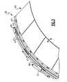
- FIG. 3is a perspective view of a section of the VAFN
- FIG. 4illustrates a gas turbine engine having a VAFN and a first boundary layer control device
- FIG. 5illustrates a gas turbine engine having a VAFN, a first boundary layer control device and a second boundary layer control device for achieving a slim line nacelle.
- a gas turbine engine 10typically includes (in serial flow communication) a fan 14 , a low pressure compressor 15 , a high pressure compressor 16 , a combustor 18 , a high pressure turbine 20 and a low pressure turbine 22 .
- airis pressurized in the compressors 15 , 16 and mixed with fuel in the combustor 18 for generating hot combustion gases.
- the hot combustion gasesflow through the high and low pressure turbines 20 , 22 which extract energy from the hot combustion gases.
- the high pressure turbine 20powers the high pressure compressor 16 through a shaft defined therebetween, and the low pressure turbine 22 powers the fan 14 and the low pressure compressor 15 through another shaft defined therebetween.
- the inventionis not limited to the two spool axial gas turbine architecture described and may be used with other architectures, such as a single spool axial design, a three spool axial design and other architectures.
- the gas turbine engine 10is in the form of a high bypass ratio turbofan engine mounted within a nacelle assembly 26 , in which most of the air pressurized by the fan 14 bypasses the core engine itself for the generation of propulsion thrust.
- the nacelle assembly 26includes a fan cowl 46 and a core cowl 28 within the fan cowl 46 .
- Fan discharge airflow F 1is discharged from the engine 10 through a variable area fan nozzle (VAFN) 30 defined radially between the core cowl 28 and the fan cowl 46 .
- Core exhaust gases Care discharged from the core engine through a core exhaust nozzle 32 defined between the core cowl 28 and a center plug 34 disposed coaxially therein around a longitudinal centerline axis A of the gas turbine engine 10 .
- the VAFN 30concentrically surrounds the core cowl 28 near an aftmost segment 29 of the nacelle assembly 26 .
- the VAFN 30 of the nacelle assembly 26defines a fan-nozzle discharge airflow area 36 ( FIG. 2 ) between the fan cowl 46 and the core cowl 28 for axially discharging the fan discharge airflow F 1 pressurized by the upstream fan 14 .
- the nacelle assembly 26defines an inlet lip section 38 and an inlet internal diffuser section 40 .
- the inlet lip section 38is positioned near a forward segment 31 of the fan cowl 46 .
- the inlet internal diffuser section 40is defined between a throat 42 of the fan cowl 46 and a forward face of the fan 14 .
- the fan cowl 46defines an outer surface of the nacelle assembly 26 .
- the nacelle assembly 26also defines a highlight diameter D h and a maximum diameter D max .
- the highlight diameter D hrepresents the diameter defined by the inlet lip section 38 of the nacelle assembly 26 .
- the maximum diameter D maxrepresents the peak diameter of the nacelle assembly 26 .
- the throat 42 of the nacelle assembly 26also defines a throat diameter D t .
- the maximum diameter D max of the nacelle assembly 26may be established by Extended-Range Twin-Engine Operational Performance Standards (ETOPS) requirements, in which an external airflow F 2 over the fan cowl 46 is required to remain separation free under an engine-out windmilling condition or other condition.
- ETOPS requirementsare aircraft performance standards established by the International Civil Aviation Organization. It is desirable from an engine efficiency standpoint for the external airflow F 2 to maintain attached to the fan cowl 46 during aircraft operation.
- a windmilling conditionoccurs where an engine of a twin-engine aircraft loses functionality (i.e. engine out condition).
- the damaged engineis advantageously permitted to rotate, and is driven by an airflow resulting from the forward velocity of the aircraft (i.e., the damaged engine is permitted to “windmill”).
- a diameter ratioor the ratio of the highlight diameter D h to the maximum diameter D max , is utilized to determine whether the nacelle assembly 26 achieves this ETOPS requirement and maintains an external airflow F 2 which is separation free from the fan cowl 46 .
- Current industry standardstypically use a diameter ratio of at least approximately 0.80 to achieve a separation free airflow, but other diameter ratios may be feasible.
- the nacelle assembly 26also defines a contraction ratio.
- the contraction ratiorepresents a relative thickness of the inlet lip section 38 of the nacelle assembly 26 and is represented by the ratio of a highlight area H a (ring-shaped area defined by highlight diameter D h ) and a throat area T a (ring-shaped area defined by throat diameter D t ) of the nacelle assembly 26 .
- Current industry standardstypically use a contraction ratio of approximately 1.300 to prevent the separation of the fan discharge airflow F 1 from an interior wall 59 of the fan cowl 46 , but other contraction ratios may be feasible.
- “Thick” inlet lip section designswhich are associated with large contraction ratios, increase the maximum diameter and increase the weight and the drag penalties associated with the nacelle assembly 26 .
- the nacelle assembly 26further defines an inlet lip length L lip and a fan duct length L fan .
- the increased fan discharge airflow F 1is achieved by providing the gas turbine engine 10 with a VAFN 30 and increasing the discharge airflow area 36 of the VAFN 30 during the specific flight conditions.
- the increase in the discharge airflow area 36is achieved by opening the VAFN 30 .
- the VAFN 30generally includes a synchronizing ring 41 , a static ring 43 , and a flap assembly 45 (See FIG. 3 ).
- Other VAFN designs and actuation mechanismsmay be used.
- the flap assembly 45is pivotally mounted to the static ring 43 at a multitude of hinges 47 and linked to the synchronizing ring 41 through a linkage 49 .
- An actuator assembly 51(only one shown in FIG. 3 ) selectively rotates the synchronizing ring 41 relative the static ring 43 to adjust the flap assembly 45 through the linkage 49 .
- the radial movement of the synchronizing ring 41is converted to tangential movement of the flap assembly 44 to vary the discharge airflow area 36 defined by the VAFN 30 through which the fan discharge airflow F 1 is discharged.
- the increase in the discharge airflow area 36is achieved by moving the VAFN 30 from a first position to a second (or open) position X (represented by dashed lines in FIG. 2 ) in response to a detected windmilling condition.
- the discharge airflow area 36 of the second positionis greater than the discharge airflow area 36 of the first position.
- a sensor 53detects the windmilling condition and communicates with a controller 55 to move the VAFN 30 via the actuator assembly 51 . It should be understood that the sensor 53 and the controller 55 may be programmed to detect any known flight condition.
- the second position Xrepresents moving the VAFN 30 to approximately 20% of its opening capability during the windmilling condition, although the actual percentage the VAFN 30 is opened will depend on design specific parameters of the gas turbine engine. A person of ordinary skill in the art would know how to design appropriate actuation and control systems to achieve comparable results with an alternative VAFN design.
- the increased fan discharge airflow F 1is achieved by providing the gas turbine engine with a variable pitch fan blade.
- the opening of the VAFN 30 during windmilling conditionsallows for a reduction in the maximum diameter D max of the nacelle assembly 26 while maintaining an external airflow F 2 which is separation free from the fan cowl 46 . Therefore, the nacelle assembly 26 achieves an improved (i.e. larger) diameter ratio. Further, the improved diameter ratio results in a weight savings and a reduction in nacelle drag (i.e., slim-line nacelle).
- the VAFN 30is returned to its first position (represented by solid lines) during normal cruise operation of the aircraft.
- a slim-line nacelle 50which includes a first boundary layer control device 52 in addition to the VAFN 30 .
- the slim line nacelle 50offers additional nacelle drag and weight benefits over the nacelle assembly 26 .
- the first boundary layer control device 52is positioned at the inlet lip section 38 of the slim line nacelle 50 .
- the first boundary layer control device 52introduces an airflow F 4 near the inlet lip section 38 in a direction defined by an intake airflow F 3 prior to the onset of separation of the fan discharge airflow F 1 from the interior wall 59 of the slim line nacelle 50 .
- the first boundary layer control device 52addresses any distortion associated with the fan discharge airflow F 1 as the fan discharge airflow F 1 is communicated from an upstream end of the engine 10 toward the downstream end.
- the first boundary layer control device 52may introduce the airflow F 4 by injection or suction of airflow near the inlet lip section 38 .
- fluid injection jet devicesfor injection of airflow
- blowing slotsfor suction of airflow
- the nacellemay include any known boundary layer control technology.
- the first boundary layer control device 52is actuated to generate the airflow F 4 in response to detection of at least one operability condition.
- the operability conditionis detected by the sensor 53 .
- the sensor 53communicates the detection of the operability condition to the controller 55 , which then actuates the first boundary layer control device 52 to generate the airflow F 4 .
- a person of ordinary skill in the artwould understand how to program the sensor 53 and the controller 55 for performing these functions.
- the operability conditionincludes a static condition. Static conditions occur at low speeds (i.e., just prior to take-off).
- the operability conditionincludes a cross-wind condition. Cross-wind conditions are experienced during takeoff as the aircraft travels down the runway (i.e., where the aircraft experiences airflow in a roughly perpendicular direction with respect to the movement of the aircraft down the runway).
- the operability conditionincludes a high angle of attack condition. High angle of attack conditions are experienced where the aircraft is traveling at low speeds and the angle of incidence of the airflow relative to the inlet lip section 38 of the slim line nacelle 50 is relatively large. It should be understood that first boundary layer control device 52 may be controlled during any operability condition experienced by an aircraft during operation.
- the discharge airflow area 36 of the VAFN 30may be increased simultaneously with the generation of the airflow F 4 by the first boundary layer control device 52 during the operability conditions to achieve further weight and drag reductions.
- both the VAFN 30 and the boundary layer control device 52are utilized during all static conditions, cross-wind conditions, and high angle of attack conditions.
- the controller 55is programmable to move the VAFN 30 to a position representing approximately 10% of its opening capability during cross-wind conditions and high angle of attack conditions, and to approximately 20% of its opening capability during static conditions.
- the first boundary layer control device 52is turned off during windmilling conditions and during normal cruise operation of the aircraft to achieve optimal performance.
- the first boundary layer control device 52 and the VAFN 30may be utilized simultaneously during the operability conditions to achieve a nacelle having a reduced contraction ratio while maintaining non-separation of the fan discharge airflow F 1 from the interior wall 59 of the slim line nacelle 50 . Therefore, corresponding weight and drag benefits are achieved by the slim-line nacelle 50 .
- the nacelle 58includes a second boundary layer control device 60 in addition to the first boundary layer control device 52 and the VAFN 30 .
- the second boundary layer control device 60is identical to the configuration of the first boundary layer control device 52 except that the second boundary layer control device 60 is positioned downstream from the first boundary layer control device and near the inlet internal diffuser section 40 .
- the second boundary layer control device 60generates an airflow F 5 at the inlet internal diffuser section 40 to prevent separation of the fan discharge airflow F 1 from the interior wall 59 near this area of the nacelle 58 .
- the second boundary layer control device 60is actuated by the controller 55 in response to detection of at least one operability condition.
- the second boundary layer control device 60is utilized to generate the airflow F 5 during static conditions, cross-wind conditions, and high angle of attack conditions. Utilization of the second boundary layer control device 60 at the inlet internal diffuser section 40 of the nacelle 58 enables a reduction in the inlet lip length L lip and the fan duct length L fan , thereby enabling a weight reduction in the nacelle design.
- the second boundary layer control device 60is shut off during windmilling conditions and during normal cruise operation of the aircraft.
- the VAFN 30 , the first boundary layer control device 52 , and the second boundary layer control device 60are exploited simultaneously during at least one of the operability conditions.
- the VAFN 30 , the first boundary layer control device 52 and the second boundary layer control device 60are simultaneously utilized during all static conditions, cross-wind conditions and high angle of attack conditions which are detected by the sensor 53 .
- the slim-line nacelle 58achieves further drag reduction benefits in response to the simultaneous utilization of all three technologies during diverse flight requirements.
Landscapes
- Engineering & Computer Science (AREA)
- Chemical & Material Sciences (AREA)
- Combustion & Propulsion (AREA)
- Mechanical Engineering (AREA)
- General Engineering & Computer Science (AREA)
- Structures Of Non-Positive Displacement Pumps (AREA)
- Wind Motors (AREA)
- Control Of Turbines (AREA)
Abstract
Description
Claims (14)
Priority Applications (4)
| Application Number | Priority Date | Filing Date | Title |
|---|---|---|---|
| US11/584,030US7797944B2 (en) | 2006-10-20 | 2006-10-20 | Gas turbine engine having slim-line nacelle |
| US12/832,254US8353164B2 (en) | 2006-10-20 | 2010-07-08 | Gas turbine engine having slim-line nacelle |
| US12/832,280US8726632B2 (en) | 2006-10-20 | 2010-07-08 | Gas turbine engine having slim-line nacelle |
| US14/248,444US8844294B2 (en) | 2006-10-20 | 2014-04-09 | Gas turbine engine having slim-line nacelle |
Applications Claiming Priority (1)
| Application Number | Priority Date | Filing Date | Title |
|---|---|---|---|
| US11/584,030US7797944B2 (en) | 2006-10-20 | 2006-10-20 | Gas turbine engine having slim-line nacelle |
Related Child Applications (2)
| Application Number | Title | Priority Date | Filing Date |
|---|---|---|---|
| US12/832,280DivisionUS8726632B2 (en) | 2006-10-20 | 2010-07-08 | Gas turbine engine having slim-line nacelle |
| US12/832,254DivisionUS8353164B2 (en) | 2006-10-20 | 2010-07-08 | Gas turbine engine having slim-line nacelle |
Publications (2)
| Publication Number | Publication Date |
|---|---|
| US20080092548A1 US20080092548A1 (en) | 2008-04-24 |
| US7797944B2true US7797944B2 (en) | 2010-09-21 |
Family
ID=39316590
Family Applications (4)
| Application Number | Title | Priority Date | Filing Date |
|---|---|---|---|
| US11/584,030Active2029-07-22US7797944B2 (en) | 2006-10-20 | 2006-10-20 | Gas turbine engine having slim-line nacelle |
| US12/832,254Active2027-12-08US8353164B2 (en) | 2006-10-20 | 2010-07-08 | Gas turbine engine having slim-line nacelle |
| US12/832,280Active2029-07-01US8726632B2 (en) | 2006-10-20 | 2010-07-08 | Gas turbine engine having slim-line nacelle |
| US14/248,444ActiveUS8844294B2 (en) | 2006-10-20 | 2014-04-09 | Gas turbine engine having slim-line nacelle |
Family Applications After (3)
| Application Number | Title | Priority Date | Filing Date |
|---|---|---|---|
| US12/832,254Active2027-12-08US8353164B2 (en) | 2006-10-20 | 2010-07-08 | Gas turbine engine having slim-line nacelle |
| US12/832,280Active2029-07-01US8726632B2 (en) | 2006-10-20 | 2010-07-08 | Gas turbine engine having slim-line nacelle |
| US14/248,444ActiveUS8844294B2 (en) | 2006-10-20 | 2014-04-09 | Gas turbine engine having slim-line nacelle |
Country Status (1)
| Country | Link |
|---|---|
| US (4) | US7797944B2 (en) |
Cited By (16)
| Publication number | Priority date | Publication date | Assignee | Title |
|---|---|---|---|---|
| US20100058769A1 (en)* | 2007-03-05 | 2010-03-11 | United Technologies Corporation | Fan variable area nozzle for a gas turbine engine fan nacelle with drive ring actuation system |
| US20130266419A1 (en)* | 2011-12-20 | 2013-10-10 | Rolls-Royce Plc | Active flow control intake for a gas turbine engine |
| US20140338324A1 (en)* | 2013-05-14 | 2014-11-20 | The Boeing Company | Shape Memory Alloy Actuation System for Variable Area Fan Nozzle |
| US9021813B2 (en) | 2011-07-18 | 2015-05-05 | The Boeing Company | Cable-actuated variable area fan nozzle with elastomeric seals |
| US20160084162A1 (en)* | 2014-09-23 | 2016-03-24 | Pratt & Whitney Cananda Corp. | Gas turbine engine inlet |
| US9920653B2 (en) | 2012-12-20 | 2018-03-20 | United Technologies Corporation | Low pressure ratio fan engine having a dimensional relationship between inlet and fan size |
| US9932933B2 (en) | 2012-12-20 | 2018-04-03 | United Technologies Corporation | Low pressure ratio fan engine having a dimensional relationship between inlet and fan size |
| US9938848B2 (en) | 2015-04-23 | 2018-04-10 | Pratt & Whitney Canada Corp. | Rotor assembly with wear member |
| US9957807B2 (en) | 2015-04-23 | 2018-05-01 | Pratt & Whitney Canada Corp. | Rotor assembly with scoop |
| US20180187697A1 (en)* | 2017-01-05 | 2018-07-05 | Pratt & Whitney Canada Corp. | Turbofan nacelle assembly with flow disruptor |
| US10167088B2 (en) | 2015-10-19 | 2019-01-01 | General Electric Company | Crosswind performance aircraft engine spinner |
| US10378554B2 (en) | 2014-09-23 | 2019-08-13 | Pratt & Whitney Canada Corp. | Gas turbine engine with partial inlet vane |
| US10526894B1 (en) | 2016-09-02 | 2020-01-07 | United Technologies Corporation | Short inlet with low solidity fan exit guide vane arrangements |
| US10724540B2 (en) | 2016-12-06 | 2020-07-28 | Pratt & Whitney Canada Corp. | Stator for a gas turbine engine fan |
| US11313241B2 (en)* | 2019-11-29 | 2022-04-26 | Rolls-Royce Plc | Nacelle for a gas turbine engine |
| US11415048B2 (en)* | 2020-05-13 | 2022-08-16 | Rolls-Royce Plc | Nacelle for gas turbine engine |
Families Citing this family (31)
| Publication number | Priority date | Publication date | Assignee | Title |
|---|---|---|---|---|
| US7721551B2 (en)* | 2006-06-29 | 2010-05-25 | United Technologies Corporation | Fan variable area nozzle for a gas turbine engine fan nacelle |
| US7797944B2 (en) | 2006-10-20 | 2010-09-21 | United Technologies Corporation | Gas turbine engine having slim-line nacelle |
| US7870721B2 (en)* | 2006-11-10 | 2011-01-18 | United Technologies Corporation | Gas turbine engine providing simulated boundary layer thickness increase |
| US20080273961A1 (en) | 2007-03-05 | 2008-11-06 | Rosenkrans William E | Flutter sensing and control system for a gas turbine engine |
| US8408491B2 (en)* | 2007-04-24 | 2013-04-02 | United Technologies Corporation | Nacelle assembly having inlet airfoil for a gas turbine engine |
| US8402739B2 (en) | 2007-06-28 | 2013-03-26 | United Technologies Corporation | Variable shape inlet section for a nacelle assembly of a gas turbine engine |
| US9004399B2 (en) | 2007-11-13 | 2015-04-14 | United Technologies Corporation | Nacelle flow assembly |
| US8186942B2 (en) | 2007-12-14 | 2012-05-29 | United Technologies Corporation | Nacelle assembly with turbulators |
| US8192147B2 (en) | 2007-12-14 | 2012-06-05 | United Technologies Corporation | Nacelle assembly having inlet bleed |
| US7716932B2 (en)* | 2008-07-24 | 2010-05-18 | Spirit Aerosystems, Inc. | Dilating fan duct nozzle |
| US20110004388A1 (en)* | 2009-07-01 | 2011-01-06 | United Technologies Corporation | Turbofan temperature control with variable area nozzle |
| WO2011159374A2 (en)* | 2010-03-08 | 2011-12-22 | The Penn State Research Foundation | Double-ducted fan |
| US8549834B2 (en) | 2010-10-21 | 2013-10-08 | United Technologies Corporation | Gas turbine engine with variable area fan nozzle |
| US8517612B2 (en) | 2011-06-30 | 2013-08-27 | United Technologies Corporation | Bearing oiling system |
| US9932121B2 (en) | 2012-06-22 | 2018-04-03 | United Technologies Corporation | Turbomachine flow stability enhancement device control |
| WO2014051662A1 (en)* | 2012-09-28 | 2014-04-03 | United Technologies Corporation | Gas turbine engine having support structure with swept leading edge |
| US9989009B2 (en)* | 2012-10-31 | 2018-06-05 | The Boeing Company | Methods and apparatus for sealing variable area fan nozzles of jet engines |
| US8616777B1 (en) | 2012-11-16 | 2013-12-31 | Pratt & Whitney Canada Corp. | Bearing assembly with inner ring |
| WO2014197030A2 (en)* | 2013-03-12 | 2014-12-11 | United Technologies Corporation | Expanding shell flow control device |
| WO2014158244A2 (en)* | 2013-03-14 | 2014-10-02 | Rolls-Royce North American Technologies, Inc. | Intercooled gas turbine with closed combined power cycle |
| US10040563B1 (en)* | 2013-04-11 | 2018-08-07 | Geoffrey P. Pinto | Dual panel actuator system for jet engines |
| US10465538B2 (en)* | 2014-11-21 | 2019-11-05 | General Electric Company | Gas turbine engine with reversible fan |
| US9915225B2 (en)* | 2015-02-06 | 2018-03-13 | United Technologies Corporation | Propulsion system arrangement for turbofan gas turbine engine |
| US10308368B2 (en) | 2015-10-30 | 2019-06-04 | General Electric Company | Turbofan engine and method of reducing air flow separation therein |
| GB201521871D0 (en)* | 2015-12-11 | 2016-01-27 | Rolls Royce Plc | Nacelle |
| US10208709B2 (en) | 2016-04-05 | 2019-02-19 | United Technologies Corporation | Fan blade removal feature for a gas turbine engine |
| US10533497B2 (en)* | 2016-04-18 | 2020-01-14 | United Technologies Corporation | Short inlet with integrated liner anti-icing |
| US10337349B2 (en) | 2016-04-27 | 2019-07-02 | United Technologies Corporation | Anti-windmilling system for a gas turbine engine |
| GB202007011D0 (en)* | 2020-05-13 | 2020-06-24 | Rolls Royce Plc | Nacelle for gas turbine engine |
| US11781506B2 (en) | 2020-06-03 | 2023-10-10 | Rtx Corporation | Splitter and guide vane arrangement for gas turbine engines |
| GB2610451B (en)* | 2022-01-18 | 2024-01-03 | Lynley Ashley Adrian | Turbofan engine efficient ducting |
Citations (48)
| Publication number | Priority date | Publication date | Assignee | Title |
|---|---|---|---|---|
| US3222863A (en) | 1963-10-07 | 1965-12-14 | Boeing Co | Aerodynamic inlet |
| US3568694A (en) | 1968-05-08 | 1971-03-09 | Lockheed Aircraft Corp | Jet engine installation for noise control |
| US3664612A (en) | 1969-12-22 | 1972-05-23 | Boeing Co | Aircraft engine variable highlight inlet |
| GB1312619A (en) | 1969-10-03 | 1973-04-04 | Secr Defence | Air intakes for gas turbine engines |
| GB1336724A (en) | 1970-11-03 | 1973-11-07 | Secr Defence | Gas turbine engine air intakes |
| GB1382809A (en) | 1971-12-04 | 1975-02-05 | Rolls Royce | Air intakes for gas turbine engines |
| US4044973A (en) | 1975-12-29 | 1977-08-30 | The Boeing Company | Nacelle assembly and mounting structures for a turbofan jet propulsion engine |
| US4083181A (en) | 1976-06-14 | 1978-04-11 | The United States Of America As Represented By The Administrator Of The National Aeronautics And Space Administration | Gas turbine engine with recirculating bleed |
| US4147029A (en) | 1976-01-02 | 1979-04-03 | General Electric Company | Long duct mixed flow gas turbine engine |
| US4722357A (en) | 1986-04-11 | 1988-02-02 | United Technologies Corporation | Gas turbine engine nacelle |
| US4865268A (en) | 1987-06-19 | 1989-09-12 | Mtu Motoren - Und Turbinen-Union Muenchen | Jet engine nacelle |
| US4899958A (en) | 1988-12-05 | 1990-02-13 | Mitsubishi Jukogyo Kabushiki Kaisha | Air intake system of an aircraft |
| US4912921A (en)* | 1988-03-14 | 1990-04-03 | Sundstrand Corporation | Low speed spool emergency power extraction system |
| US4993663A (en) | 1989-06-01 | 1991-02-19 | General Electric Company | Hybrid laminar flow nacelle |
| US5000399A (en) | 1990-02-23 | 1991-03-19 | General Electric Company | Variable contour annular air inlet for an aircraft engine nacelle |
| US5012639A (en) | 1989-01-23 | 1991-05-07 | United Technologies Corporation | Buffer region for the nacelle of a gas turbine engine |
| US5058617A (en) | 1990-07-23 | 1991-10-22 | General Electric Company | Nacelle inlet for an aircraft gas turbine engine |
| US5127222A (en) | 1989-01-23 | 1992-07-07 | United Technologies Corporation | Buffer region for the nacelle of a gas turbine engine |
| US5143329A (en) | 1990-06-01 | 1992-09-01 | General Electric Company | Gas turbine engine powered aircraft environmental control system and boundary layer bleed |
| US5145126A (en) | 1990-11-16 | 1992-09-08 | Rolls-Royce Plc | Engine nacelle |
| US5177957A (en) | 1990-03-22 | 1993-01-12 | Mtu Motoren-Und Turbinen-Union Muchen Gmbh | Propfan turbine engine |
| US5261227A (en)* | 1992-11-24 | 1993-11-16 | General Electric Company | Variable specific thrust turbofan engine |
| US5284012A (en) | 1991-05-16 | 1994-02-08 | General Electric Company | Nacelle cooling and ventilation system |
| US5297765A (en) | 1992-11-02 | 1994-03-29 | Rohr, Inc. | Turbine engine nacelle laminar flow control arrangement |
| US5447283A (en)* | 1994-02-02 | 1995-09-05 | Grumman Aerospace Corporation | Blown boundary layer control system for a jet aircraft |
| US5586431A (en) | 1994-12-06 | 1996-12-24 | United Technologies Corporation | Aircraft nacelle ventilation and engine exhaust nozzle cooling |
| US5593112A (en) | 1994-12-06 | 1997-01-14 | United Technologies Corporation | Nacelle air pump for vector nozzles for aircraft |
| US5743488A (en) | 1994-12-05 | 1998-04-28 | Short Brothers Plc | Aerodynamic low drag structure |
| US5987880A (en) | 1997-07-08 | 1999-11-23 | Mcdonnell Douglas Corporation | Supersonic engine, multi-port thrust reversing system |
| US6089505A (en) | 1997-07-22 | 2000-07-18 | Mcdonnell Douglas Corporation | Mission adaptive inlet |
| US6109566A (en) | 1999-02-25 | 2000-08-29 | United Technologies Corporation | Vibration-driven acoustic jet controlling boundary layer separation |
| US6129311A (en) | 1997-07-30 | 2000-10-10 | The Boeing Company | Engine nacelle outer cowl panel with integral track fairings |
| US6179251B1 (en) | 1998-02-06 | 2001-01-30 | Northrop Grumman Corporation | Thin inlet lip design for low drag and reduced nacelle size |
| US6334753B1 (en) | 2000-07-31 | 2002-01-01 | United Technologies Corporation | Streamlined bodies with counter-flow fluid injection |
| US6340135B1 (en) | 2000-05-30 | 2002-01-22 | Rohr, Inc. | Translating independently mounted air inlet system for aircraft turbofan jet engine |
| US6360989B1 (en) | 1999-09-17 | 2002-03-26 | Rolls-Royce Plc | Nacelle assembly for a gas turbine engine |
| US6379110B1 (en) | 1999-02-25 | 2002-04-30 | United Technologies Corporation | Passively driven acoustic jet controlling boundary layers |
| US6390418B1 (en) | 1999-02-25 | 2002-05-21 | United Technologies Corporation | Tangentially directed acoustic jet controlling boundary layer |
| US6651929B2 (en) | 2001-10-29 | 2003-11-25 | Pratt & Whitney Canada Corp. | Passive cooling system for auxiliary power unit installation |
| US6655632B1 (en) | 2002-08-27 | 2003-12-02 | General Electric Company | System and method for actively changing an effective flow-through area of an inlet region of an aircraft engine |
| US6708711B2 (en) | 2001-11-02 | 2004-03-23 | Airbus France | Air inlet for commercial aircraft jet engine nacelle |
| US6764043B2 (en) | 2002-12-11 | 2004-07-20 | The Boeing Company | Rotatable scarf inlet for an aircraft engine and method of using the same |
| US6971229B2 (en) | 2003-02-26 | 2005-12-06 | The Nordam Group, Inc. | Confluent exhaust nozzle |
| US7048229B2 (en) | 2000-09-26 | 2006-05-23 | Techland Research, Inc. | Low sonic boom inlet for supersonic aircraft |
| US7090165B2 (en) | 2003-06-02 | 2006-08-15 | Rolls-Royce Plc | Aeroengine nacelle |
| US7131612B2 (en) | 2003-07-29 | 2006-11-07 | Pratt & Whitney Canada Corp. | Nacelle inlet lip anti-icing with engine oil |
| US7165744B2 (en) | 2004-01-21 | 2007-01-23 | Rolls-Royce Plc | Turbine engine arrangements |
| US7617670B2 (en) | 2006-03-31 | 2009-11-17 | Lockheed Martin Corporation | Flow control redistribution to mitigate high cycle fatigue |
Family Cites Families (87)
| Publication number | Priority date | Publication date | Assignee | Title |
|---|---|---|---|---|
| FR980347A (en) | 1943-02-05 | 1951-05-10 | Use of a knowingly established gradient along the walls of a solid effrps submerged in a liquid or gaseous fluid | |
| US2948111A (en)* | 1955-05-02 | 1960-08-09 | Doak Aircraft Co Inc | Means to increase static pressure and enhance forward thrust of aircraft components |
| US2915262A (en)* | 1957-09-26 | 1959-12-01 | Douglas Aircraft Co Inc | Vortex inhibitor for aircraft jet engines |
| US3059878A (en) | 1958-11-26 | 1962-10-23 | Rolls Royce | Auxiliary air intakes for jet engines adapted for vertical take-off |
| US3074232A (en) | 1959-07-25 | 1963-01-22 | Soyer Robert | Devices forming the mouthpieces of air admission pipes for jet engines for aircraft |
| US3119581A (en) | 1960-06-18 | 1964-01-28 | Dunlop Rubber Co | Securing means for inflatable inlet device |
| GB1070458A (en) | 1964-06-12 | 1967-06-01 | Boeing Co | Separator for removing foreign matter from a gas stream |
| US3298637A (en)* | 1964-06-15 | 1967-01-17 | Lee Shao-Tang | Engine inlet protective screen arrangement |
| GB1111219A (en) | 1966-02-14 | 1968-04-24 | Rolls Royce | Gas turbine engine |
| US3472027A (en)* | 1966-12-22 | 1969-10-14 | Gen Electric | Control systems for axial flow compressors particularly adapted for use in gas turbine engines |
| GB1190774A (en) | 1967-04-05 | 1970-05-06 | Rolls Royce | Improvements relating to the Silencing of Gas Turbine Engines |
| US3524611A (en)* | 1968-07-22 | 1970-08-18 | Kurt Frank | Controllable air duct for vertical and short take-off and landing type of air vehicle |
| FR1589899A (en)* | 1968-10-24 | 1970-04-06 | ||
| US3541794A (en)* | 1969-04-23 | 1970-11-24 | Gen Electric | Bifurcated fan duct thrust reverser |
| GB1252193A (en) | 1969-09-26 | 1971-11-03 | ||
| US3583417A (en)* | 1969-10-07 | 1971-06-08 | Boeing Co | Sound suppressor for jet engine inlet |
| US3611724A (en)* | 1970-01-07 | 1971-10-12 | Gen Electric | Choked inlet noise suppression device for a turbofan engine |
| GB1244292A (en)* | 1970-01-14 | 1971-08-25 | Rolls Royce | Gas turbine engine |
| US3575259A (en)* | 1970-04-10 | 1971-04-20 | Boeing Co | Retractable noise suppression system |
| US3618699A (en) | 1970-04-27 | 1971-11-09 | Gen Electric | Multiple pure tone noise suppression device for an aircraft gas turbine engine |
| US3716209A (en)* | 1970-06-01 | 1973-02-13 | Mini Of Technology | Fluid dynamic lift generating or control force generating structures |
| US3699682A (en)* | 1971-01-04 | 1972-10-24 | Mc Donnell Douglas Corp | Turbofan engine thrust reverser |
| US3736750A (en)* | 1971-03-12 | 1973-06-05 | Rolls Royce | Power plant |
| US3770228A (en)* | 1971-12-08 | 1973-11-06 | Lockheed Aircraft Corp | Air inlet flap |
| US3905566A (en)* | 1972-08-29 | 1975-09-16 | Edwin R Anderson | Jet engine intake protection system |
| US3932058A (en)* | 1974-06-07 | 1976-01-13 | United Technologies Corporation | Control system for variable pitch fan propulsor |
| US4068469A (en)* | 1975-05-29 | 1978-01-17 | The United States Of America As Represented By The Administrator Of The National Aeronautics And Space Administration | Variable thrust nozzle for quiet turbofan engine and method of operating same |
| US4007891A (en)* | 1975-09-12 | 1977-02-15 | The United States Of America As Represented By The Administrator Of The National Aeronautics And Space Administration | Jet engine air intake system |
| US4012013A (en)* | 1976-02-05 | 1977-03-15 | The Boeing Company | Variable camber inlet for supersonic aircraft |
| US4055946A (en)* | 1976-03-29 | 1977-11-01 | United Technologies Corporation | Twin-spool gas turbine power plant with means to spill compressor interstage airflow |
| FR2370171A1 (en)* | 1976-11-05 | 1978-06-02 | Snecma | METHOD AND DEVICE FOR REDUCING TURBOMACHINE NOISE |
| US4132240A (en)* | 1977-03-28 | 1979-01-02 | General Electric Company | Variable double lip quiet inlet |
| US4154256A (en)* | 1978-03-29 | 1979-05-15 | The United States Of America As Represented By The Administrator Of The National Aeronautics And Space Administration | Self stabilizing sonic inlet |
| US4242864A (en)* | 1978-05-25 | 1981-01-06 | The United States Of America As Represented By The Administrator Of The National Aeronautics And Space Administration | Integrated control system for a gas turbine engine |
| US4220171A (en)* | 1979-05-14 | 1980-09-02 | The United States Of America As Represented By The Administrator Of The National Aeronautics And Space Administration | Curved centerline air intake for a gas turbine engine |
| US4351502A (en)* | 1980-05-21 | 1982-09-28 | The Boeing Company | Continuous skin, variable camber airfoil edge actuating mechanism |
| US4475702A (en)* | 1982-12-28 | 1984-10-09 | The Boeing Company | Variable camber leading edge assembly for an airfoil |
| US4540143A (en)* | 1983-08-04 | 1985-09-10 | The Boeing Company | Nacelle/wing assembly with wake control device |
| US4738416A (en)* | 1986-09-26 | 1988-04-19 | Quiet Nacelle Corporation | Nacelle anti-icing system |
| GB8630754D0 (en)* | 1986-12-23 | 1987-02-04 | Rolls Royce Plc | Turbofan gas turbine engine |
| US5014933A (en)* | 1989-04-27 | 1991-05-14 | The Boeing Company | Translating lip aircraft cowling structure adapted for noise reduction |
| US5141182A (en)* | 1990-06-01 | 1992-08-25 | General Electric Company | Gas turbine engine fan duct base pressure drag reduction |
| US5156362A (en)* | 1991-05-31 | 1992-10-20 | General Electric Company | Jet engine fan nacelle |
| DE4134051C2 (en)* | 1991-10-15 | 1995-02-02 | Mtu Muenchen Gmbh | Turbine jet engine with fan |
| US5361828A (en)* | 1993-02-17 | 1994-11-08 | General Electric Company | Scaled heat transfer surface with protruding ramp surface turbulators |
| US5357742A (en)* | 1993-03-12 | 1994-10-25 | General Electric Company | Turbojet cooling system |
| DE4426351B4 (en)* | 1994-07-25 | 2006-04-06 | Alstom | Combustion chamber for a gas turbine |
| WO1996012269A1 (en)* | 1994-10-13 | 1996-04-25 | The Boeing Company | Jet engine fan noise reduction system utilizing electro pneumatic transducers |
| FR2730763B1 (en) | 1995-02-21 | 1997-03-14 | Hispano Suiza Sa | DOWNSTREAM SHUTTER REVERSER FOR TURBOJET |
| FR2736682B1 (en)* | 1995-07-12 | 1997-08-14 | Hispano Suiza Sa | DOUBLE FLOW TURBOMACHINE DRIVE INVERTER WITH DISSYMMETRIC DOORS |
| US5803410A (en)* | 1995-12-01 | 1998-09-08 | The United States Of America As Represented By The Administrator Of The National Aeronautics And Space Administration | Skin friction reduction by micro-blowing technique |
| US5665916A (en)* | 1996-06-28 | 1997-09-09 | The United States Of America As Represented By The Administrator Of The National Aeronautics And Space Administration | Fuel line based acoustic flame-out detection system |
| US5813625A (en)* | 1996-10-09 | 1998-09-29 | Mcdonnell Douglas Helicopter Company | Active blowing system for rotorcraft vortex interaction noise reduction |
| US6055805A (en)* | 1997-08-29 | 2000-05-02 | United Technologies Corporation | Active rotor stage vibration control |
| US5934611A (en)* | 1997-10-20 | 1999-08-10 | Northrop Grumman Corporation | Low drag inlet design using injected duct flow |
| GB9723022D0 (en)* | 1997-11-01 | 1998-01-07 | Rolls Royce Plc | Gas turbine apparatus |
| US5841079A (en)* | 1997-11-03 | 1998-11-24 | Northrop Grumman Corporation | Combined acoustic and anti-ice engine inlet liner |
| US5971328A (en) | 1998-01-15 | 1999-10-26 | Kota; Sridhar | System for varying a surface contour |
| US6129309A (en)* | 1998-07-24 | 2000-10-10 | Mcdonnell Douglas Corporation | Aircraft engine apparatus with reduced inlet vortex |
| US6259976B1 (en)* | 1999-09-25 | 2001-07-10 | Jerome H. Lemelson | Fuzzy logic based emergency flight control with thrust vectoring |
| US6375118B1 (en)* | 2000-08-30 | 2002-04-23 | The Boeing Company | High frequency excitation apparatus and method for reducing jet and cavity noise |
| DE10059212A1 (en)* | 2000-11-29 | 2002-06-13 | Grohe Armaturen Friedrich | Shower fixture |
| US6471477B2 (en)* | 2000-12-22 | 2002-10-29 | The Boeing Company | Jet actuators for aerodynamic surfaces |
| FR2820716B1 (en) | 2001-02-15 | 2003-05-30 | Eads Airbus Sa | PROCESS FOR DEFROSTING BY FORCED CIRCULATION OF A FLUID, OF A REACTION ENGINE AIR INLET COVER AND DEVICE FOR ITS IMPLEMENTATION |
| DE10330023A1 (en) | 2002-07-20 | 2004-02-05 | Alstom (Switzerland) Ltd. | Vortex generator used in the swirling and mixing of fuel/air mixtures in pre-mixing combustion chambers comprises an outlet opening for targeted introduction of a secondary flow into the core flow of the wake produced |
| US6763651B2 (en) | 2002-10-25 | 2004-07-20 | The Boeing Company | Active system for wide area suppression of engine vortex |
| US6793177B2 (en) | 2002-11-04 | 2004-09-21 | The Bonutti 2003 Trust-A | Active drag and thrust modulation system and method |
| DK1603798T3 (en) | 2003-03-03 | 2011-02-14 | Flexsys Inc | Adaptable and flexible blade and rotor system |
| GB2402196B (en) | 2003-05-29 | 2006-05-17 | Rolls Royce Plc | A laminar flow nacelle for an aircraft engine |
| GB0312505D0 (en) | 2003-05-31 | 2003-07-09 | Rolls Royce Plc | Engine nozzle |
| US7631483B2 (en)* | 2003-09-22 | 2009-12-15 | General Electric Company | Method and system for reduction of jet engine noise |
| DE102004024007B4 (en) | 2004-05-13 | 2007-10-11 | Airbus Deutschland Gmbh | Aircraft component, in particular wings |
| US20050274103A1 (en) | 2004-06-10 | 2005-12-15 | United Technologies Corporation | Gas turbine engine inlet with noise reduction features |
| US7255309B2 (en) | 2004-07-14 | 2007-08-14 | The Boeing Company | Vernier active flow control effector |
| GB0418196D0 (en)* | 2004-08-14 | 2004-09-15 | Rolls Royce Plc | Boundary layer control arrangement |
| US20060155432A1 (en) | 2005-01-07 | 2006-07-13 | United Technologies Corporation | Methods and systems for monitoring atmospheric conditions, predicting turbulent atmospheric conditions and optimizing flight paths of aircraft |
| GB0505246D0 (en) | 2005-03-15 | 2005-04-20 | Rolls Royce Plc | Engine noise |
| US20070214795A1 (en)* | 2006-03-15 | 2007-09-20 | Paul Cooker | Continuous real time EGT margin control |
| US7797944B2 (en) | 2006-10-20 | 2010-09-21 | United Technologies Corporation | Gas turbine engine having slim-line nacelle |
| US7870721B2 (en) | 2006-11-10 | 2011-01-18 | United Technologies Corporation | Gas turbine engine providing simulated boundary layer thickness increase |
| US8408491B2 (en)* | 2007-04-24 | 2013-04-02 | United Technologies Corporation | Nacelle assembly having inlet airfoil for a gas turbine engine |
| US8205430B2 (en) | 2007-05-16 | 2012-06-26 | United Technologies Corporation | Variable geometry nacelle assembly for a gas turbine engine |
| US8727267B2 (en)* | 2007-05-18 | 2014-05-20 | United Technologies Corporation | Variable contraction ratio nacelle assembly for a gas turbine engine |
| US7766280B2 (en)* | 2007-05-29 | 2010-08-03 | United Technologies Corporation | Integral suction device with acoustic panel |
| US8402739B2 (en) | 2007-06-28 | 2013-03-26 | United Technologies Corporation | Variable shape inlet section for a nacelle assembly of a gas turbine engine |
| US9228534B2 (en) | 2007-07-02 | 2016-01-05 | United Technologies Corporation | Variable contour nacelle assembly for a gas turbine engine |
| US9004399B2 (en) | 2007-11-13 | 2015-04-14 | United Technologies Corporation | Nacelle flow assembly |
- 2006
- 2006-10-20USUS11/584,030patent/US7797944B2/enactiveActive
- 2010
- 2010-07-08USUS12/832,254patent/US8353164B2/enactiveActive
- 2010-07-08USUS12/832,280patent/US8726632B2/enactiveActive
- 2014
- 2014-04-09USUS14/248,444patent/US8844294B2/enactiveActive
Patent Citations (50)
| Publication number | Priority date | Publication date | Assignee | Title |
|---|---|---|---|---|
| US3222863A (en) | 1963-10-07 | 1965-12-14 | Boeing Co | Aerodynamic inlet |
| US3568694A (en) | 1968-05-08 | 1971-03-09 | Lockheed Aircraft Corp | Jet engine installation for noise control |
| GB1312619A (en) | 1969-10-03 | 1973-04-04 | Secr Defence | Air intakes for gas turbine engines |
| US3664612A (en) | 1969-12-22 | 1972-05-23 | Boeing Co | Aircraft engine variable highlight inlet |
| GB1336724A (en) | 1970-11-03 | 1973-11-07 | Secr Defence | Gas turbine engine air intakes |
| GB1382809A (en) | 1971-12-04 | 1975-02-05 | Rolls Royce | Air intakes for gas turbine engines |
| US4044973A (en) | 1975-12-29 | 1977-08-30 | The Boeing Company | Nacelle assembly and mounting structures for a turbofan jet propulsion engine |
| US4147029A (en) | 1976-01-02 | 1979-04-03 | General Electric Company | Long duct mixed flow gas turbine engine |
| US4083181A (en) | 1976-06-14 | 1978-04-11 | The United States Of America As Represented By The Administrator Of The National Aeronautics And Space Administration | Gas turbine engine with recirculating bleed |
| US4722357A (en) | 1986-04-11 | 1988-02-02 | United Technologies Corporation | Gas turbine engine nacelle |
| US4865268A (en) | 1987-06-19 | 1989-09-12 | Mtu Motoren - Und Turbinen-Union Muenchen | Jet engine nacelle |
| US4912921A (en)* | 1988-03-14 | 1990-04-03 | Sundstrand Corporation | Low speed spool emergency power extraction system |
| US4899958A (en) | 1988-12-05 | 1990-02-13 | Mitsubishi Jukogyo Kabushiki Kaisha | Air intake system of an aircraft |
| US5012639A (en) | 1989-01-23 | 1991-05-07 | United Technologies Corporation | Buffer region for the nacelle of a gas turbine engine |
| US5127222A (en) | 1989-01-23 | 1992-07-07 | United Technologies Corporation | Buffer region for the nacelle of a gas turbine engine |
| US4993663A (en) | 1989-06-01 | 1991-02-19 | General Electric Company | Hybrid laminar flow nacelle |
| US5000399A (en) | 1990-02-23 | 1991-03-19 | General Electric Company | Variable contour annular air inlet for an aircraft engine nacelle |
| US5177957A (en) | 1990-03-22 | 1993-01-12 | Mtu Motoren-Und Turbinen-Union Muchen Gmbh | Propfan turbine engine |
| US5143329A (en) | 1990-06-01 | 1992-09-01 | General Electric Company | Gas turbine engine powered aircraft environmental control system and boundary layer bleed |
| US5058617A (en) | 1990-07-23 | 1991-10-22 | General Electric Company | Nacelle inlet for an aircraft gas turbine engine |
| US5145126A (en) | 1990-11-16 | 1992-09-08 | Rolls-Royce Plc | Engine nacelle |
| US5351476A (en) | 1991-05-16 | 1994-10-04 | General Electric Company | Nacelle cooling and ventilation system |
| US5284012A (en) | 1991-05-16 | 1994-02-08 | General Electric Company | Nacelle cooling and ventilation system |
| US5297765A (en) | 1992-11-02 | 1994-03-29 | Rohr, Inc. | Turbine engine nacelle laminar flow control arrangement |
| US5261227A (en)* | 1992-11-24 | 1993-11-16 | General Electric Company | Variable specific thrust turbofan engine |
| US5447283A (en)* | 1994-02-02 | 1995-09-05 | Grumman Aerospace Corporation | Blown boundary layer control system for a jet aircraft |
| US5743488A (en) | 1994-12-05 | 1998-04-28 | Short Brothers Plc | Aerodynamic low drag structure |
| US5586431A (en) | 1994-12-06 | 1996-12-24 | United Technologies Corporation | Aircraft nacelle ventilation and engine exhaust nozzle cooling |
| US5593112A (en) | 1994-12-06 | 1997-01-14 | United Technologies Corporation | Nacelle air pump for vector nozzles for aircraft |
| US5987880A (en) | 1997-07-08 | 1999-11-23 | Mcdonnell Douglas Corporation | Supersonic engine, multi-port thrust reversing system |
| US6089505A (en) | 1997-07-22 | 2000-07-18 | Mcdonnell Douglas Corporation | Mission adaptive inlet |
| US6260567B1 (en) | 1997-07-22 | 2001-07-17 | The Boeing Company | Mission adaptive inlet |
| US6129311A (en) | 1997-07-30 | 2000-10-10 | The Boeing Company | Engine nacelle outer cowl panel with integral track fairings |
| US6179251B1 (en) | 1998-02-06 | 2001-01-30 | Northrop Grumman Corporation | Thin inlet lip design for low drag and reduced nacelle size |
| US6109566A (en) | 1999-02-25 | 2000-08-29 | United Technologies Corporation | Vibration-driven acoustic jet controlling boundary layer separation |
| US6390418B1 (en) | 1999-02-25 | 2002-05-21 | United Technologies Corporation | Tangentially directed acoustic jet controlling boundary layer |
| US6379110B1 (en) | 1999-02-25 | 2002-04-30 | United Technologies Corporation | Passively driven acoustic jet controlling boundary layers |
| US6360989B1 (en) | 1999-09-17 | 2002-03-26 | Rolls-Royce Plc | Nacelle assembly for a gas turbine engine |
| US6340135B1 (en) | 2000-05-30 | 2002-01-22 | Rohr, Inc. | Translating independently mounted air inlet system for aircraft turbofan jet engine |
| US6334753B1 (en) | 2000-07-31 | 2002-01-01 | United Technologies Corporation | Streamlined bodies with counter-flow fluid injection |
| US7048229B2 (en) | 2000-09-26 | 2006-05-23 | Techland Research, Inc. | Low sonic boom inlet for supersonic aircraft |
| US6651929B2 (en) | 2001-10-29 | 2003-11-25 | Pratt & Whitney Canada Corp. | Passive cooling system for auxiliary power unit installation |
| US6708711B2 (en) | 2001-11-02 | 2004-03-23 | Airbus France | Air inlet for commercial aircraft jet engine nacelle |
| US6655632B1 (en) | 2002-08-27 | 2003-12-02 | General Electric Company | System and method for actively changing an effective flow-through area of an inlet region of an aircraft engine |
| US6764043B2 (en) | 2002-12-11 | 2004-07-20 | The Boeing Company | Rotatable scarf inlet for an aircraft engine and method of using the same |
| US6971229B2 (en) | 2003-02-26 | 2005-12-06 | The Nordam Group, Inc. | Confluent exhaust nozzle |
| US7090165B2 (en) | 2003-06-02 | 2006-08-15 | Rolls-Royce Plc | Aeroengine nacelle |
| US7131612B2 (en) | 2003-07-29 | 2006-11-07 | Pratt & Whitney Canada Corp. | Nacelle inlet lip anti-icing with engine oil |
| US7165744B2 (en) | 2004-01-21 | 2007-01-23 | Rolls-Royce Plc | Turbine engine arrangements |
| US7617670B2 (en) | 2006-03-31 | 2009-11-17 | Lockheed Martin Corporation | Flow control redistribution to mitigate high cycle fatigue |
Non-Patent Citations (7)
| Title |
|---|
| Extended European Search Report for Application No. 08252429.9 mailed Nov. 26, 2008. |
| U.S. Appl. No. 11/595,040, filed Nov. 10, 2006, Winter, et al. |
| U.S. Appl. No. 11/739,216, filed Apr. 27, 2007, Jain, et al. |
| U.S. Appl. No. 11/749,260, filed May 16, 2007, Jain, et al. |
| U.S. Appl. No. 11/750,398, filed May 18, 2007, Jain, et al. |
| U.S. Appl. No. 11/769,749, filed Jun. 28, 2007, Jain, et al. |
| U.S. Appl. No. 11/772,287, filed Jul. 2, 2007, Jain, et al. |
Cited By (27)
| Publication number | Priority date | Publication date | Assignee | Title |
|---|---|---|---|---|
| US8316646B2 (en)* | 2007-03-05 | 2012-11-27 | United Technologies Corporation | Fan variable area nozzle for a gas turbine engine fan nacelle with drive ring actuation system |
| US20100058769A1 (en)* | 2007-03-05 | 2010-03-11 | United Technologies Corporation | Fan variable area nozzle for a gas turbine engine fan nacelle with drive ring actuation system |
| US9021813B2 (en) | 2011-07-18 | 2015-05-05 | The Boeing Company | Cable-actuated variable area fan nozzle with elastomeric seals |
| US20130266419A1 (en)* | 2011-12-20 | 2013-10-10 | Rolls-Royce Plc | Active flow control intake for a gas turbine engine |
| US11015550B2 (en) | 2012-12-20 | 2021-05-25 | Raytheon Technologies Corporation | Low pressure ratio fan engine having a dimensional relationship between inlet and fan size |
| US10301971B2 (en) | 2012-12-20 | 2019-05-28 | United Technologies Corporation | Low pressure ratio fan engine having a dimensional relationship between inlet and fan size |
| US11781447B2 (en) | 2012-12-20 | 2023-10-10 | Rtx Corporation | Low pressure ratio fan engine having a dimensional relationship between inlet and fan size |
| US9920653B2 (en) | 2012-12-20 | 2018-03-20 | United Technologies Corporation | Low pressure ratio fan engine having a dimensional relationship between inlet and fan size |
| US9932933B2 (en) | 2012-12-20 | 2018-04-03 | United Technologies Corporation | Low pressure ratio fan engine having a dimensional relationship between inlet and fan size |
| US11781505B2 (en) | 2012-12-20 | 2023-10-10 | Rtx Corporation | Low pressure ratio fan engine having a dimensional relationship between inlet and fan size |
| US11286811B2 (en) | 2012-12-20 | 2022-03-29 | Raytheon Technologies Corporation | Low pressure ratio fan engine having a dimensional relationship between inlet and fan size |
| US20140338324A1 (en)* | 2013-05-14 | 2014-11-20 | The Boeing Company | Shape Memory Alloy Actuation System for Variable Area Fan Nozzle |
| US9581145B2 (en)* | 2013-05-14 | 2017-02-28 | The Boeing Company | Shape memory alloy actuation system for variable area fan nozzle |
| US10145301B2 (en)* | 2014-09-23 | 2018-12-04 | Pratt & Whitney Canada Corp. | Gas turbine engine inlet |
| US10378554B2 (en) | 2014-09-23 | 2019-08-13 | Pratt & Whitney Canada Corp. | Gas turbine engine with partial inlet vane |
| US20160084162A1 (en)* | 2014-09-23 | 2016-03-24 | Pratt & Whitney Cananda Corp. | Gas turbine engine inlet |
| US10837361B2 (en) | 2014-09-23 | 2020-11-17 | Pratt & Whitney Canada Corp. | Gas turbine engine inlet |
| US11118601B2 (en) | 2014-09-23 | 2021-09-14 | Pratt & Whitney Canada Corp. | Gas turbine engine with partial inlet vane |
| US9938848B2 (en) | 2015-04-23 | 2018-04-10 | Pratt & Whitney Canada Corp. | Rotor assembly with wear member |
| US9957807B2 (en) | 2015-04-23 | 2018-05-01 | Pratt & Whitney Canada Corp. | Rotor assembly with scoop |
| US10167088B2 (en) | 2015-10-19 | 2019-01-01 | General Electric Company | Crosswind performance aircraft engine spinner |
| US10526894B1 (en) | 2016-09-02 | 2020-01-07 | United Technologies Corporation | Short inlet with low solidity fan exit guide vane arrangements |
| US10724540B2 (en) | 2016-12-06 | 2020-07-28 | Pratt & Whitney Canada Corp. | Stator for a gas turbine engine fan |
| US20180187697A1 (en)* | 2017-01-05 | 2018-07-05 | Pratt & Whitney Canada Corp. | Turbofan nacelle assembly with flow disruptor |
| US10690146B2 (en)* | 2017-01-05 | 2020-06-23 | Pratt & Whitney Canada Corp. | Turbofan nacelle assembly with flow disruptor |
| US11313241B2 (en)* | 2019-11-29 | 2022-04-26 | Rolls-Royce Plc | Nacelle for a gas turbine engine |
| US11415048B2 (en)* | 2020-05-13 | 2022-08-16 | Rolls-Royce Plc | Nacelle for gas turbine engine |
Also Published As
| Publication number | Publication date |
|---|---|
| US20140216002A1 (en) | 2014-08-07 |
| US20100269486A1 (en) | 2010-10-28 |
| US20080092548A1 (en) | 2008-04-24 |
| US8726632B2 (en) | 2014-05-20 |
| US20100269512A1 (en) | 2010-10-28 |
| US8844294B2 (en) | 2014-09-30 |
| US8353164B2 (en) | 2013-01-15 |
Similar Documents
| Publication | Publication Date | Title |
|---|---|---|
| US7797944B2 (en) | Gas turbine engine having slim-line nacelle | |
| US11396847B2 (en) | Flutter sensing and control system for a gas turbine engine | |
| EP1921291B1 (en) | Gas turbine engine providing simulated boundary layer thickness increase | |
| US8205430B2 (en) | Variable geometry nacelle assembly for a gas turbine engine | |
| EP1988266B1 (en) | Nacelle assembly having inlet airfoil for a gas turbine engine | |
| EP2074305B1 (en) | Gas turbine engine system comprising a translating core cowl and operational method thereof | |
| US8286415B2 (en) | Turbofan engine having inner fixed structure including ducted passages | |
| JPH06280616A (en) | Operating method of aircraft bypass-turbofan engine | |
| US8272204B2 (en) | Core cowl airfoil for a gas turbine engine |
Legal Events
| Date | Code | Title | Description |
|---|---|---|---|
| AS | Assignment | Owner name:UNITED TECHNOLOGIES CORPORATION, CONNECTICUT Free format text:ASSIGNMENT OF ASSIGNORS INTEREST;ASSIGNORS:MORFORD, STEPHENA.;LARKIN, MICHAEL J.;REEL/FRAME:018451/0973 Effective date:20061018 | |
| STCF | Information on status: patent grant | Free format text:PATENTED CASE | |
| FPAY | Fee payment | Year of fee payment:4 | |
| MAFP | Maintenance fee payment | Free format text:PAYMENT OF MAINTENANCE FEE, 8TH YEAR, LARGE ENTITY (ORIGINAL EVENT CODE: M1552) Year of fee payment:8 | |
| AS | Assignment | Owner name:RAYTHEON TECHNOLOGIES CORPORATION, MASSACHUSETTS Free format text:CHANGE OF NAME;ASSIGNOR:UNITED TECHNOLOGIES CORPORATION;REEL/FRAME:054062/0001 Effective date:20200403 | |
| AS | Assignment | Owner name:RAYTHEON TECHNOLOGIES CORPORATION, CONNECTICUT Free format text:CORRECTIVE ASSIGNMENT TO CORRECT THE AND REMOVE PATENT APPLICATION NUMBER 11886281 AND ADD PATENT APPLICATION NUMBER 14846874. TO CORRECT THE RECEIVING PARTY ADDRESS PREVIOUSLY RECORDED AT REEL: 054062 FRAME: 0001. ASSIGNOR(S) HEREBY CONFIRMS THE CHANGE OF ADDRESS;ASSIGNOR:UNITED TECHNOLOGIES CORPORATION;REEL/FRAME:055659/0001 Effective date:20200403 | |
| MAFP | Maintenance fee payment | Free format text:PAYMENT OF MAINTENANCE FEE, 12TH YEAR, LARGE ENTITY (ORIGINAL EVENT CODE: M1553); ENTITY STATUS OF PATENT OWNER: LARGE ENTITY Year of fee payment:12 | |
| AS | Assignment | Owner name:RTX CORPORATION, CONNECTICUT Free format text:CHANGE OF NAME;ASSIGNOR:RAYTHEON TECHNOLOGIES CORPORATION;REEL/FRAME:064714/0001 Effective date:20230714 |