US7797009B2 - Method and system for providing a network protocol for utility services - Google Patents
Method and system for providing a network protocol for utility servicesDownload PDFInfo
- Publication number
- US7797009B2 US7797009B2US11/560,938US56093806AUS7797009B2US 7797009 B2US7797009 B2US 7797009B2US 56093806 AUS56093806 AUS 56093806AUS 7797009 B2US7797009 B2US 7797009B2
- Authority
- US
- United States
- Prior art keywords
- gateway
- network
- powered meter
- utility network
- constant
- Prior art date
- Legal status (The legal status is an assumption and is not a legal conclusion. Google has not performed a legal analysis and makes no representation as to the accuracy of the status listed.)
- Active, expires
Links
Images


Classifications
- G—PHYSICS
- G01—MEASURING; TESTING
- G01D—MEASURING NOT SPECIALLY ADAPTED FOR A SPECIFIC VARIABLE; ARRANGEMENTS FOR MEASURING TWO OR MORE VARIABLES NOT COVERED IN A SINGLE OTHER SUBCLASS; TARIFF METERING APPARATUS; MEASURING OR TESTING NOT OTHERWISE PROVIDED FOR
- G01D5/00—Mechanical means for transferring the output of a sensing member; Means for converting the output of a sensing member to another variable where the form or nature of the sensing member does not constrain the means for converting; Transducers not specially adapted for a specific variable
- G—PHYSICS
- G08—SIGNALLING
- G08C—TRANSMISSION SYSTEMS FOR MEASURED VALUES, CONTROL OR SIMILAR SIGNALS
- G08C15/00—Arrangements characterised by the use of multiplexing for the transmission of a plurality of signals over a common path
- G08C15/06—Arrangements characterised by the use of multiplexing for the transmission of a plurality of signals over a common path successively, i.e. using time division
- G—PHYSICS
- G01—MEASURING; TESTING
- G01D—MEASURING NOT SPECIALLY ADAPTED FOR A SPECIFIC VARIABLE; ARRANGEMENTS FOR MEASURING TWO OR MORE VARIABLES NOT COVERED IN A SINGLE OTHER SUBCLASS; TARIFF METERING APPARATUS; MEASURING OR TESTING NOT OTHERWISE PROVIDED FOR
- G01D4/00—Tariff metering apparatus
- G01D4/002—Remote reading of utility meters
- G—PHYSICS
- G06—COMPUTING OR CALCULATING; COUNTING
- G06F—ELECTRIC DIGITAL DATA PROCESSING
- G06F15/00—Digital computers in general; Data processing equipment in general
- G06F15/16—Combinations of two or more digital computers each having at least an arithmetic unit, a program unit and a register, e.g. for a simultaneous processing of several programs
- G—PHYSICS
- G08—SIGNALLING
- G08C—TRANSMISSION SYSTEMS FOR MEASURED VALUES, CONTROL OR SIMILAR SIGNALS
- G08C15/00—Arrangements characterised by the use of multiplexing for the transmission of a plurality of signals over a common path
- H—ELECTRICITY
- H04—ELECTRIC COMMUNICATION TECHNIQUE
- H04L—TRANSMISSION OF DIGITAL INFORMATION, e.g. TELEGRAPHIC COMMUNICATION
- H04L12/00—Data switching networks
- H04L12/28—Data switching networks characterised by path configuration, e.g. LAN [Local Area Networks] or WAN [Wide Area Networks]
- H—ELECTRICITY
- H04—ELECTRIC COMMUNICATION TECHNIQUE
- H04L—TRANSMISSION OF DIGITAL INFORMATION, e.g. TELEGRAPHIC COMMUNICATION
- H04L67/00—Network arrangements or protocols for supporting network services or applications
- H04L67/01—Protocols
- H04L67/12—Protocols specially adapted for proprietary or special-purpose networking environments, e.g. medical networks, sensor networks, networks in vehicles or remote metering networks
- H—ELECTRICITY
- H04—ELECTRIC COMMUNICATION TECHNIQUE
- H04W—WIRELESS COMMUNICATION NETWORKS
- H04W40/00—Communication routing or communication path finding
- H04W40/02—Communication route or path selection, e.g. power-based or shortest path routing
- H04W40/04—Communication route or path selection, e.g. power-based or shortest path routing based on wireless node resources
- H04W40/08—Communication route or path selection, e.g. power-based or shortest path routing based on wireless node resources based on transmission power
- H—ELECTRICITY
- H04—ELECTRIC COMMUNICATION TECHNIQUE
- H04W—WIRELESS COMMUNICATION NETWORKS
- H04W40/00—Communication routing or communication path finding
- H04W40/24—Connectivity information management, e.g. connectivity discovery or connectivity update
- H04W40/246—Connectivity information discovery
- Y—GENERAL TAGGING OF NEW TECHNOLOGICAL DEVELOPMENTS; GENERAL TAGGING OF CROSS-SECTIONAL TECHNOLOGIES SPANNING OVER SEVERAL SECTIONS OF THE IPC; TECHNICAL SUBJECTS COVERED BY FORMER USPC CROSS-REFERENCE ART COLLECTIONS [XRACs] AND DIGESTS
- Y02—TECHNOLOGIES OR APPLICATIONS FOR MITIGATION OR ADAPTATION AGAINST CLIMATE CHANGE
- Y02B—CLIMATE CHANGE MITIGATION TECHNOLOGIES RELATED TO BUILDINGS, e.g. HOUSING, HOUSE APPLIANCES OR RELATED END-USER APPLICATIONS
- Y02B90/00—Enabling technologies or technologies with a potential or indirect contribution to GHG emissions mitigation
- Y02B90/20—Smart grids as enabling technology in buildings sector
- Y—GENERAL TAGGING OF NEW TECHNOLOGICAL DEVELOPMENTS; GENERAL TAGGING OF CROSS-SECTIONAL TECHNOLOGIES SPANNING OVER SEVERAL SECTIONS OF THE IPC; TECHNICAL SUBJECTS COVERED BY FORMER USPC CROSS-REFERENCE ART COLLECTIONS [XRACs] AND DIGESTS
- Y04—INFORMATION OR COMMUNICATION TECHNOLOGIES HAVING AN IMPACT ON OTHER TECHNOLOGY AREAS
- Y04S—SYSTEMS INTEGRATING TECHNOLOGIES RELATED TO POWER NETWORK OPERATION, COMMUNICATION OR INFORMATION TECHNOLOGIES FOR IMPROVING THE ELECTRICAL POWER GENERATION, TRANSMISSION, DISTRIBUTION, MANAGEMENT OR USAGE, i.e. SMART GRIDS
- Y04S20/00—Management or operation of end-user stationary applications or the last stages of power distribution; Controlling, monitoring or operating thereof
- Y04S20/30—Smart metering, e.g. specially adapted for remote reading
Definitions
- the field of the inventionrelates generally to computer systems and more particularly relates to a method and system for providing a network protocol for utility services.
- AMRAutomated Meter Reading
- AMRAdvanced Mobile Radio
- Fixed networksmay be based on wireless or wireline. However, the real advantages are with systems based on fixed wireless networks. Fixed network systems have some important distinctive advantages, brought about by the frequent (typically at least daily) consumption data collection, in comparison with mobile systems, which merely provide a more reliable method of collecting monthly meter reads for billing purposes.
- a categorizationhas evolved as the AMR industry developed, generally differentiating between one-way and two-way fixed wireless data networks.
- Prior systemsrequire that each meter module on the network be a two-way module, i.e. contain a receiver circuit in the meter module.
- two-way communication featuressuch as on-demand meter reading and other remote commands for meter configuration and control are generally desirable, they may not be required for the entire meter population of a utility. Since the inclusion of a receiver in the meter module contributes significant cost to the module, it would be most desirable to allow a utility service company the flexibility to deploy an AMR network, which may contain and support both one-way and two-way meter modules.
- a disadvantage of networks with distributed intelligence among the data collection nodesis the limited storage and processing power of the data collection nodes.
- a system that could efficiently transfer all the raw data from the meter modules to the network's central databasewould therefore be desirable, since it would allow for more backup and archiving options and also for more complex function calculations and processing on the raw meter data.
- a computer-implemented methodcomprises discovering a utility network, wherein a constant powered meter sends network discovery messages to find the utility network that it is a part of. Neighboring meters in the utility network are discovered, wherein the constant powered meter sends hello or status messages periodically. The constant powered meters are registered with the utility network. The constant powered meter sends a node registration message to a gateway.
- the gatewayis the intermediate agent/central node in the network through whom a family of constant powered meters and battery powered meters communicate with the central server of the utility network.
- FIG. 1illustrates a block diagram of an exemplary utility network, according to one embodiment of the present invention
- FIG. 2illustrates an exemplary computer architecture for use with the present system, according to one embodiment of the invention
- FIG. 3illustrates an exemplary common link layer packet header, according to one embodiment
- FIG. 4illustrates an exemplary network discovery packet header, according to one embodiment
- FIG. 5illustrates an exemplary hello message header, according to one embodiment
- FIG. 6illustrates an exemplary node registration message used when registering to a network, according to one embodiment
- FIG. 7illustrates an exemplary node registration acknowledgement message, according to one embodiment
- FIG. 8illustrates an exemplary route update message sent by gateway to update settings for a CPD node, according to one embodiment
- FIG. 9illustrates an exemplary route update acknowledgement message, according to one embodiment.
- a computer-implemented methodcomprises discovering a utility network, wherein a constant powered meter sends network discovery messages to find the utility network that it is a part of. Neighboring meters in the utility network are discovered, wherein the constant powered meter sends hello or status messages periodically. The constant powered meter are registered with the utility network. The constant powered meter sends a node registration message to a gateway. The gateway is the intermediate agent/central node in the network through whom a family of constant powered meters communicate with the central server of the utility network.
- the present inventionalso relates to apparatus for performing the operations herein.
- This apparatusmay be specifically constructed for the required purposes, or it may comprise a general-purpose computer selectively activated or reconfigured by a computer program stored in the computer.
- a computer programmay be stored in a computer readable storage medium, such as, but is not limited to, any type of disk including floppy disks, optical disks, CD-ROMs, and magnetic-optical disks, read-only memories (“ROMs”), random access memories (“RAMs”), EPROMs, EEPROMs, magnetic or optical cards, or any type of media suitable for storing electronic instructions, and each coupled to a computer system bus.
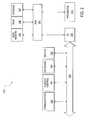
- FIG. 1illustrates a block diagram of an exemplary utility network 100 , according to one embodiment of the present invention.
- Utility network 100includes a data communications network 110 , at least one gateway 120 , at least one battery powered device (BPD) 130 , and at least one constant powered device (CPD) 140 .
- BPDbattery powered device
- CPDconstant powered device
- a centralized server 150collects data from battery powered devices 130 , and constant power devices 140 . Data is communicated between nodes and server 150 in utility network 100 according to a network utility protocol.
- the present network communication protocolis designed to operate in a dense multi-hop radio network, where nodes are fixed to a specific location. There is a central node (e.g., gateway 120 ) which plays a significant role in managing the network.
- BPD 130 and CPD 140have very limited amounts of available memory and processing capabilities.
- Gateway 120is a central node which communicates with all of the other nodes, either directly or via relay.
- CPD 140may be one or more meters and relays in the utility network 100 . Meters are able to relay packets between other meters (CPDs 140 and BPDs 130 ), and between meters and the gateway 120 .
- BPD 130may be one or more battery powered meters and relays. They are limited in transmit power, uptime, and processing capabilities compared to CPDs 140 . According to one embodiment, BPDs 130 are not able to relay packets. BPDs' 130 packets might be relayed by regular meters.
- the topology of the network 100is expected to change slowly. Nodes, such as BPDs 130 and CPDs 140 stay in the network for years, and the characteristics of a radio link between them changes quite slowly, except for transient noise sources and obstacles for RF propagation.
- the applications using network 100are utility meter reading, management required for those meters, and management of other devices owned by utility companies.
- FIG. 2illustrates an exemplary computer architecture for use with the present system, according to one embodiment of the invention.
- Computer architecture 200can be used to implement gateway 120 , BPDs 130 , CPDs 140 or a server 150 of FIG. 1 .
- One embodiment of architecture 200comprises a system bus 220 for communicating information, and a processor 210 coupled to bus 220 for processing information.
- Architecture 200further comprises a random access memory (RAM) or other dynamic storage device 225 (referred to herein as main memory), coupled to bus 220 for storing information and instructions to be executed by processor 210 .
- Main memory 225also may be used for storing temporary variables or other intermediate information during execution of instructions by processor 210 .
- Architecture 200also may include a read only memory (ROM) and/or other static storage device 226 coupled to bus 220 for storing static information and instructions used by processor 210 .
- ROMread only memory
- a data storage device 227such as a magnetic disk or optical disc and its corresponding drive may also be coupled to computer system 200 for storing information and instructions.
- Architecture 200can also be coupled to a second I/O bus 250 via an I/O interface 230 .
- a plurality of I/O devicesmay be coupled to I/O bus 250 , including a display device 243 , an input device (e.g., an alphanumeric input device 242 and/or a cursor control device 241 ).
- the communication device 240allows for access to other computers (servers or clients) via a network.
- the communication device 240may comprise a modem, a network interface card, a wireless network interface or other well known interface device, such as those used for coupling to Ethernet, token ring, straight IP, or other types of networks.
- Nodessuch as BPDs 130 and CPDs 140 , discover available networks (network 110 ), select one they should join, and then register themselves with the gateway 120 .
- This central node gateway 120keeps track of the network topology and capabilities of all devices in its control, and also other devices. Based on this info, it calculates, and distributes path and other state parameters to all registered devices, such as BPDs 130 and CPDs 140 .
- Nodesmaintain local state and the states of their immediate neighbors, and periodically send updates about their local state to central node 120 .
- the central node 120precomputes a set of routes and figures out which neighbours a particular node might talk with for the purpose of forwarding packets (rather than neighbour discovery). For each device 130 , 140 , the central node 120 calculates the packet transmit power setting and tries to minimize the amount of radio interference between neighbours. It distributes this state to all devices in the network, updating it when necessary. According to one embodiment IPv6 is used for the network layer protocol. Nodes 130 , 140 registering with a central node 120 form a logical subnet and the central node 120 acts as a default router.
- Each node 130 , 140is identified by a unique link layer address assigned to its radio interface. Typically each one has only a single interface. Gateways can have multiple interfaces, where each interface is dedicated to a separate channel. Link layer addresses are typically 6 bytes long. The Link Layer Broadcast address is in hex ff:ff:ff:ff:ff (all ones). Packets destined to local broadcast are processed by everyone who receives them.
- FIG. 3illustrates an exemplary common link layer packet header 300 , according to one embodiment.
- Link layer header 300is contains the following fields:
- PID Protocol IDidentifier for the upper layer protocol.
- R Reserved TTL Time-to-liveR Reserved CurOff Current Offset; index to source address array identifying the location of the current hop.
- P Priority bit1 indicates high priority.
- Hop Address 1 . . . NAddresses of intermediate hops for source routed messages. Destination Network address of the destination. This can Address be the broadcast address.
- Protocol IDProvides the protocol that the packet is carrying. This may be a specific network protocol being used, or link layer routing protocol.
- TTLThis is set at each node 120 , 130 , where the packet is generated.
- the initial valueis set to ‘Default TTL’, and is configurable.
- the TTLis decremented on L2-fwd. [L2-pkt-out only if it has been through L2-fwd.]
- Priority BitIf the priority bit is set, high priority processing is requested for these messages. This maps to 2 levels of priority provided by the MAC/PHY layer.
- Source Route BitIndicates whether the packet contains the entire hop-by-hop route to be used between source and destination.
- Address CountIndicates the total number of addresses contained in the data link header including the source, destination, and any intermediate addresses for source routed packets.
- Source AddressThis is the address of the node generating. According to one embodiment, it can not be set to the broadcast address.
- Hop AddressesThis is the list of addresses for source routed messages. It can contain the broadcast address.
- Destination AddressThis is the address of the intended recipient of the packet. This can be the broadcast address.
- Link Layer ForwardingIf the source route bit is set, the packet header contains the full path the packet will take. Note that a packet can be source routed between two nodes with no intermediate hops (i.e., AddrCnt is 2, and the destination address is either a node or broadcast address). This is a mechanism used to interrogate individual nodes 120 , 140 from a terminal such as a debugging mobile station.
- the intended destinationis the gateway 120 , regardless of the destination address of the packet.
- the forwarding pathis not entered because the packet is received locally.
- TTLgets decremented when a packet goes through a node's L2-fwd. Packets going through L2-fwd are dropped when TTL becomes zero. Messages with zero TTL destined to the local host are delivered up the stack. Nodes 130 , 140 which are sending messages to the gateway 120 without using full source route set TTL to be at least the number of hops on the longest path they have leading to the gateway 120 .
- the maximum TTLcan be configured by the administrator. According to one embodiment, packets sent with the destination address set to L2broadcast are not forwarded.
- Delivery of unicast packetsis normally acknowledged by the MAC layer. Broadcasted packets are not acknowledged and it is possible to send unacknowledged unicast packets.
- the MAC layerreports the number of retries and the eventual success of the transmission. The network layer keeps counters of this information on a per neighbour basis.
- the routing subsystemis divided into 3 components:
- CPD 140starts network discovery when:
- BPDs 130start network discovery if the link to its nominated master (CPD node 140 ) has been severed.
- CPD node 140searches for active networks by walking through all channels, while sending broadcasted network discovery (ND) messages and waiting for an acknowledgment. If CPD 140 receives such a message, it responds with a unicast acknowledgment within ‘Fast ND Time’. These ND messages, and their acknowledgments are sent with max TX power setting. This first ND is sent with ‘All flag’ reset, if a node eavesdrops an acknowledgment coming from some other node, it will not send a 2nd acknowledgment. CPD 140 has the ability to move fast to next channel if this one is unused.
- NDbroadcasted network discovery
- CPD 140When CPD 140 discovers an active network it stops on that channel, and does a slower scan. This slower scan is done using another ND message with a longer response time, ‘Slow ND Time’, and will have ‘All flag’ set. This causes all the neighbors to respond. Out of all the neighbours on this channel, the best one is picked to represent the network. Goodness of network is determined by looking at info reported in acks, a node which minimizes the value from formula ‘(15 ⁇ (RSSI_from_hello+RSSI_from_ack)/2)*4+# of hops*8+gw_load’ is chosen. ‘gw_load’ is value distributed by the gateway, and varies from 0 ⁇ >128, where 0 indicates least load. The CPD 140 walks through all channels, and gathers info about those networks. The walk of channels is done 3 times; the channels for which network info has been found are not visited again.
- CPD 140Based on the info collected from all channels, a network which minimizes the aforementioned value is elected.
- CPD 140returns to this channel, and does a scan with a HELLO message in order to gather information about neighbors.
- Response timer in HELLOis set to ‘Slow ND Time’.
- the list of neighborsis then sent in a node registration (NREG) message to the gateway 120 .
- NREGnode registration
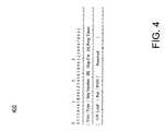
- FIG. 4illustrates an exemplary network discovery packet header 400 , according to one embodiment.
- the network discovery message header 400contains the following fields:
- Type Type1 for ND, 2 for ND_ACK Seq Number Sequence number; filled in at the transmitter of the message, copied as such to acknowledgment.
- Hop Cnt Distance from the gateway 120in number of hops. Set to 0 on NDs, filled with distance from gateway 120. Filled with 0x7f if no paths to gateway 120 exist. A All flag; set to 1 if everyone hearing this ND should acknowledge, 0 if duplicate acknowledgments should be suppressed. When suppression is requested, the acknowledgments are sent to broadcast address.
- Resp Timer Timer for sending acknowledgments. Valueis in seconds, 0 means no ack necessary.
- GW Loadrepresents the load of a gateway 120; set to 0 by transmitter of ND, in ND_ACK filled with the latest ‘GW load’number received from the gateway 120 either via NREG_ACK, or RUPD. Filled with 0xfe if no info available. RSSI Set to 0 when sending this message, filled with RSSI of received ND in acknowledgment.
- Nodes 130 , 140limit the rate at which they send out ND messages.
- the Resp Timer fieldis filled in by the transmitter of the ND recipient. It indicates the time window within which the ND_ACK 400 is sent by the recipient. It is set to ‘Fast ND Time’ during fast channel scan, and to ‘Slow ND Time’ during neighbor list gathering.
- Periodic HELLOs-Map of the network 100is maintained using HELLO protocol and passive monitoring of traffic.
- CPDs 140 and gateways 120periodically broadcast HELLO messages, which are used by neighbors to collect link quality information.
- Periodic HELLOsare sent at the TX power indicated for this node by the gateway 120 in route update (RUPD) messages. If this node has not received route update (RUPD) messages, it uses either configured TX power value, or maximum TX power setting. Periodic HELLOs are sent once per ‘HELLO Interval’.
- a nodeascertains the presence of a neighbor by the traffic it receives, specifically:
- Nodeassumes that it has lost connectivity to its neighbor if it hasn't seen traffic from it for ‘Link Max Idle Time’ period of time. When this happens, neighbor is removed from node's neighbor table. Special case are the links to upstream nodes, if CPD 140 has not been able to receive any data from its upstream neighbor, this might be due to self-interference from traffic sent by other nodes in the network 100 .
- Node 140starts sending unicast HELLO messages to at least one upstream neighbor to validate that it is still present. This is started at ‘Link Max Idle Time’/2 of idle time. Collected information is periodically sent to the gateway 120 . If CPD 140 locally determines that all the upstream neighbors are down, it initiates neighbor discovery process in this channel. If no new route to gateway 120 is found, the node enters network discovery phase.
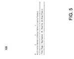
- FIG. 5illustrates an exemplary HELLO message header 500 , according to one embodiment.
- HELLO messages 500are used for searching and/or reporting the presence of a link.
- the HELLO message header 500contains following fields:
- Type Type3 for HELLO, 4 for HELLO_ACK Seq Number Sequence number; filled in at the transmitter of the message, copied as such to acknowledgment.
- R Route OK flagset to 0 by transmitter of HELLO, in acknowledgment set to 1 if it's OK to use this neighbour to send neighbour list to gateway 120.
- Hop Cnt Distance from the gateway 120in number of hops. Set to 0 on NDs, filled with distance from gateway 120. Filled with 0x7f if no paths to gateway 120 exist.
- a All flagset to 1 if everyone hearing this HELLO should acknowledge, 0 if duplicate acknowledgments should be suppressed. When supression is requested, the acknowledgments are sent to broadcast address.
- Resp Timer Timer for sending acknowledgments. Valueis in seconds, 0 means no ack necessary.
- gateway 120After the network discovery phase, there may be no valid route to gateway 120 . In addition, gateway 120 does not know that the node 130 , 140 is present. The node 130 , 140 initially registers with the gateway 120 and periodically reports its presence to it.
- a node 130 , 140In registration messages, a node 130 , 140 advertises the network protocol it wants to use, e.g. IPv6. Gateway 120 rejects the registration if it is not capable of handling this protocol. Node 130 , 140 registers itself by sending a Node Register message (NREG). If ‘NREG retry count’ number of registration attempts have not been successful, the node 130 , 140 assumes that the gateway 120 is unreachable. In that case node 130 , 140 re-enters network discovery phase.
- NREGNode Register message
- the initial NREG messagesare sent to a neighbor who claims in its ND_ACK to own a valid route to the gateway 120 . If no such neighbor exists, or if the ack for this NREG fails to arrive, the discovery process is restarted after ‘Network discovery interval’ time period has elapsed.
- a node who is in process of doing network discovery, or whose route to gateway 120 includes the source of this HELLO as one of the path elements,does not claim that it has a valid route to gateway 120 .
- the NREG messageincludes information about a node's 130 , 140 immediate neighbors and this information is used by the gateway 120 to compute routes for this and other nodes in the network 100 , and maintain a constantly updated node routing table for the network.
- gateway 120fails to receive NREG messages within ‘Node Unreachable Time’ it assumes the node 130 , 140 has disappeared from the network 100 .
- a sequence numberis used for making sure that neighbor information from a node is not processed out-of-order. It is monotonically increasing, incremented according to rules of the lollipop model. Gateway 120 stores the previously seen NREG sequence number, and discards messages that arrive out-of-order. If gateway 120 responds to a periodic NREG message with NREG_ACK with ‘N flag’ set, CPD 140 slowly scans that channel again using full TX power, and reports all its neighbors. Also it re-registers all BPDs 130 who have associated with it.
- a node 130 , 140sends NREG messages one at a time, waiting for acknowledgments before sending another one. If the acknowledgment fails to arrive within ‘NREG rexmit time’, NREG message is retransmitted. After ‘NREG rexmit count’ number of failed attempts have been made with a single message, registration attempt is given up and retried after ‘NREG interval’. A sequence number is incremented for every new message. ‘More flag’ is set in all but the last message of multipart NREG. Message number starts from zero, and is incremented by one for every message in split NREG report.
- Gateway 120updates its routing tables after the first segment has been sent, and also when all the parts of an NREG have been received.
- FIG. 6illustrates an exemplary NREG message 600 used when registering to a network 100 , according to one embodiment.
- NREG message 600is used to update the gateway's 120 map of the network 100 .
- the NREG message header 600contains following fields:
- Type Type5 for NREG. Seq Number Sequence number; filled in at the transmitter of NREG, copied as such to acknowledgment in NREG_ACK.
- NType Node type0 for CPD, 1 for BPD, 2 for CPD which has backup power through battery. M More flag; if multiple NREG messages are needed for reporting all the neighbours, this flag is set on all but last of these messages.
- N New registration flagset in NREG if this message is being sent after a channel scan done using full TX power. Gateway 120 sets this in NREG_ACK if it hasn't seen this meter before.
- 0x17 for GE KV2c electric meters0x08 for gas IMUs, 0x09 for water IMUs, 0x0B for relays.
- PD Proto IDidentifier for the network protocol used by this node. Valid IDs are IPv4 or IPv6.
- MsgN Message numberidentifies the message in sequence when multiple NREG messages are used for registration. Neighbour L2 Address Address of neighbor. A neighbor can appear multiple times in this array.
- Tx_SR Transmit success ratethis reports the ratio of successful transmissions compared against all transmit attempts. Value is from 0 to 15.
- N_RSSI RSSI of the received messagesis from 0 to 15.
- Per neighbor information(L2address and RSSI) is sent for every neighbor. Size of the packet is used in determining how many are being reported by this node. Nodes should limit the rate at which they send out NREG messages 600 .
- An NREG message 600 sent for a BPD 130contains only a single neighbor, this is the entry for CPD 140 it has selected as its master.
- FIG. 7illustrates an exemplary NREG_ACK message 700 sent in response to NREG message, according to one embodiment.
- the NREG_ACK message header 700contains following fields:
- Type Type6 for NREG_ACK. Seq Number Sequence number; copied from NREG.
- GW LoadRepresents the load of a gateway 120. Set to current load of gateway 120 on RUPD, ignored on RUPD_ACK. (RUPD refers to Route Update Message)
- Nodes 130 , 140update their current TX power setting each time they receive RUPD, NREG_ACK messages. Sending a NREG_ACK with gw load 0xff commands the node to leave the current network and restart network discovery.
- Route distributionis done to CPDs 140 . Routes are sent to a node 140 via route update (RUPD) messages. These messages contain up to 3 full node-gateway 120 paths via different upstream neighbors. Gateway 120 recalculates routes:
- Route calculationis done using shortest path first, and a single path is selected. Multiple paths are calculated, and optimized transmit power settings for each CPD are provided. A sequence number is used for making sure that path information from the gateway 120 is not processed out-of-order. In gateway 120 , the path information is stored per destination, and incremented. Gateway 120 includes additional configuration information in RUPD. Gateway 120 limits the rate at which it sends RUPD messages to optimum functional levels.
- FIG. 8illustrates an exemplary route update message 800 sent by gateway 120 to update settings for a CPD 140 node, according to one embodiment.
- RUPD messages 800contains following fields:
- Type Type7 for RUPD. Seq Number Sequence number; assigned for RUPD, copied as such to RUPD_ACK. TXPwr Transmit power which should be used for regular communication by this node. PC Path count; number of paths included in this message.
- GW LoadRepresents the load of a gateway 120. Set to current load of gateway 120 on RUPD, ignored on RUPD_ACK.
- Nodes 130 , 140update their TX power setting with the latest transmit power information from gateway 120 , each time they receive RUPD messages 600 .
- Paths listsare optional. Node's current paths are replaced if paths are included in the latest RUPD message. Path descriptors are padded to 4 byte alignment. Path elements are in order from the node 130 , 140 towards gateway 120 ; the address of the node 130 , 140 and the gateway 120 are excluded from the list. Path metric indicates goodness of the path.
- RUPD messagesuse lollipop sequence numbering. Sending a RUPD with gw load 0xff commands the node to leave the current network and restart network discovery.
- FIG. 9illustrates an exemplary route update acknowledgement message 900 , according to one embodiment.
- RUPD_ACK messages 900contains following fields:
- Type Type8 for RUPD_ACK. Seq Number Sequence number; assigned for RUPD, copied as such to RUPD_ACK. Status Status of RUPD processing; set to 0 on success, and to nonzero on failure. If node returns an error, path information has been accepted, but not the configuration info. Error codes: 0 - Success 1 - Unrecognized Parameter 2 - Invalid Parameter Value Lollipop Sequence Numbering in RUPD
- Sequence number assignment in RUPD messagesfollows lollipop model.
- Gateway 120maintains for each CPD node 140 in the network 100 a monotonically increasing sequence number. When talking to a node for the first time, the sequence number is set to 0xff. Subsequent changes in message contents increment this value; i.e. changes in path list, TX power or GW Load. When the number reaches 0xfe, the next value that gets set is 0x00. Nodes should only allow route and configuration settings updates where sequence number of the message is larger than in the previous message. Gateway 120 does not roll this number over when none of its RUPD messages have been updated for a long time (i.e. difference between assigned sequence number and acknowledged sequence number must never grow to be larger than 2 ⁇ 7 ⁇ 1.) If it does, sequence numbers are restarted from 0xff.
- NREG sequence numbersWhen a device 130 , 140 talks to a gateway 120 for the first time after deciding to join a network, it starts its sequence numbers with 0xff. This is not incremented until NREG_ACK for it has been received. After this, sequence number is incremented each time node sends an NREG.
- Gateway 120distributes configuration variables in RUPD messages. These variable values are reset when a node 130 , 140 restarts network discovery. Information in subsequent RUPD messages overwrites the previous setting. This is used in providing stateless autoconfiguration of network protocols.
- BPD 130discovers gateway 120 the same way as a CPD 140 . After it has elected a network, it goes back to that channel, and elects one of the nodes who acknowledges its 2nd HELLO as its master, and sends a unicasted ‘associate’ message to it. When multiple CPDs 140 ack this HELLO message, they are ranked based on RSSI and number of currently registered BPDs 130 . If the CPD 140 sends a NAK (e.g. due to not enough resources), the 2nd best device is tried and so on. If none of the devices is capable of handling this BPD 130 , channel scan continues. If association is successful, CPD 140 registers this BPD 130 with the network's 100 gateway 120 . CPD 140 remembers BPDs 130 which have associated with it, and if it changes gateways 120 , or if it determines that the gateway 120 has lost its state (N flag set in NREG_ACK), it re-registers all its BPDs.
- the protocol described abovedoes not allow nodes to migrate from one network to another network, unless connectivity to a gateway 120 , or its upstream neighbors have been severed.
- a full channel scanperiodically occurs to see if one can find new networks. Having a large number of nodes migrate changes the gw load component quite a bit, which could cause that same node to migrate back to original channel very soon, as it determines its original network is functionally superior to the one it had migrated to.
- gateway 120fails, it might take quite a while for all nodes to migrate to a new channel. This could be made faster, if a node 130 , 140 after discovering a new, functional network 100 returns to its old channel and broadcasts a message to its immediate neighbors saying that its about to move out. Neighbors then mark this neighbor unreachable immediately, and restart network discovery.
- nodes 130 , 140In case of a power outage, a lot of nodes 130 , 140 become active at the same time. To alleviate the flurry of network discovery messages this generates, nodes 130 , 140 store network info in persistent storage. If paths change due to NREG arriving to a gateway 120 , it sends out an NREG_ACK, and an RUPD, which in turn is acknowledged by the node doing registration. Optimization includes path information along with NREG_ACK. This contains a sequence number from the same space as route updates, Otherwise path updates could be reordered.
- LANforms an NBMA (non-broadcast-multiple-access) network. Multicast, and broadcast transmissions are possible, but the transmission has to be routed through the central node 120 . Router advertisement, router solicitation, and redirect messages are supported. CPDs 140 and BPDs 130 process routing headers when they are the final destination, and return errors if the processing of the routing header requires them to forward the packet to another node. This ensures that the nodes are not inappropriately used in relaying packets to the greater Internet, or as components in DoS attacks.
- NBMAnon-broadcast-multiple-access
- An EUI-64 identifieris constructed from link layer addresses similarly as to how it is done for Ethernet interfaces.
- the first 3 octets of the MAC addressare followed by FFFE and the last 3 octets of the MAC address.
- RUPD messagescontain an additional network prefix, and nodes generate their address from this by appending the interface identifier to this prefix.
- IPv6 neighbor cachecontains entries for nodes which are on-link as indicated by a network prefix of the address for a shared link. These might not be directly reachable, given that this is a multihop network. Definition of a neighbor in IPv6 is different from what it is at the link layer. IPv6 neighbor caches contain entries where the link layer destination is either a single address, or an array of link layer addresses. The array is for source-routing the packet through the network 100 , and contains addresses of all intermediate hops. Entries will be added as a result of receiving RUPD messages from a gateway 120 or with ICMP Redirects.
- Nexthop selection for a nodeis done by first consulting a neighbor cache for a matching entry. If no such entry exists, a link layer neighbor list is consulted. IPv6 addresses for nodes which are reachable directly from this node are constructed based on their MAC address. If the route to destination is still not found, the packet is sent to the gateway 120 . Gateway 120 responds with ICMP Redirect if the destination is located in local network, or it forwards the packets on behalf of the source. Multicast traffic originated by these nodes is always sent directly to gateway 120 .
- Configuration parametersDefault TTL TTL value in link layer header. Default: 8, min 2, max 64. Fast ND How much response time is given in ND Time used for discovering network. Default: 1 second, min 1 sec, max 127 sec. Slow ND How much response time is given in ND Time used for discovering neighbors. Default: 10 seconds, min 1 sec, max 127 sec. HELLO How frequently nodes should broadcast Interval HELLO messages after registration. One must add randomness to sending these, random component should be + ⁇ 1 ⁇ 3 of period. Default: 360 seconds, min 10 sec, max 7200 sec. Link Max If no packets are received from Idle Time a neighbor during this time period, it is determined that it's not there anymore.
Landscapes
- Engineering & Computer Science (AREA)
- General Physics & Mathematics (AREA)
- Signal Processing (AREA)
- Physics & Mathematics (AREA)
- Computer Networks & Wireless Communication (AREA)
- Medical Informatics (AREA)
- Theoretical Computer Science (AREA)
- Health & Medical Sciences (AREA)
- Computing Systems (AREA)
- General Health & Medical Sciences (AREA)
- Computer Hardware Design (AREA)
- General Engineering & Computer Science (AREA)
- Software Systems (AREA)
- Mobile Radio Communication Systems (AREA)
- Data Exchanges In Wide-Area Networks (AREA)
- Arrangements For Transmission Of Measured Signals (AREA)
- Selective Calling Equipment (AREA)
Abstract
Description
| Vers | Version number. |
| PID | Protocol ID; identifier for the upper layer |
| protocol. | |
| R | Reserved |
| TTL | Time-to-live. |
| R | Reserved |
| CurOff | Current Offset; index to source address |
| array identifying the location of the | |
| current hop. | |
| P | Priority bit; 1 indicates high priority. |
| S | Source route bit; 1 indicates that source |
| route follows. | |
| Addr Cnt | Number of address elements which follows, |
| set to 2 for packets without source routes. | |
| Will be >= 2 for packets with source routes. | |
| Source Address | Network address of the originator of the |
| packet. This can never be the broadcast address. | |
| Addresses of intermediate hops for source | |
| routed messages. | |
| Destination | Network address of the destination. This can |
| Address | be the broadcast address. |
- List of protocols with their ID values:
- 0x03: routing protocol,
- 0x04: IPv4 networking protocol,
- 0x06: IPv6 networking protocol,
- 0x07: Datalink trace.
- network discovery
- neighbour discovery and maintenance
- node registration and route distribution
- it has not associated with a gateway,
- if its communication links with its upstream neighbours have been severed,
- if its periodic NREG message to
gateway 120 fails to get acknowledged 3 times in a row.
- the first discovers network and give fast feedback about visibility of any network.
- the second message is used in gathering a complete list of neighbours.
| Vers | Version number. |
| Type | Type; 1 for ND, 2 for ND_ACK |
| Seq Number | Sequence number; filled in at the transmitter |
| of the message, copied as such to acknowledgment. | |
| Hop Cnt | Distance from the |
| Set to 0 on NDs, filled with distance from | |
| Filled with 0x7f if no paths to | |
| A | All flag; set to 1 if everyone hearing this |
| ND should acknowledge, 0 if duplicate | |
| acknowledgments should be suppressed. When | |
| suppression is requested, the acknowledgments are | |
| sent to broadcast address. | |
| Resp Timer | Timer for sending acknowledgments. Value is |
| in seconds, 0 means no ack necessary. | |
| GW Load | Represents the load of a |
| transmitter of ND, in ND_ACK filled with the | |
| latest ‘GW load’number received from the | |
| either via NREG_ACK, or RUPD. Filled with 0xfe | |
| if no info available. | |
| RSSI | Set to 0 when sending this message, filled |
| with RSSI of received ND in acknowledgment. | |
- HELLO messages periodically sent from that neighbor.
- Unicast traffic directed to any node sent from that neighbor.
- Broadcast traffic from that neighbor.
According to one embodiment, messages originating from nodes which are in the process of network discovery do not reset nexthop aging.
Neighbour Table Maintenance and Active Scanning
| Vers | Version number. |
| Type | Type; 3 for HELLO, 4 for HELLO_ACK |
| Seq Number | Sequence number; filled in at the transmitter |
| of the message, copied as such to acknowledgment. | |
| R | Route OK flag; set to 0 by transmitter of HELLO, |
| in acknowledgment set to 1 if it's OK to use | |
| this neighbour to send neighbour list to | |
| Hop Cnt | Distance from the |
| Set to 0 on NDs, filled with distance from | |
| Filled with 0x7f if no paths to | |
| A | All flag; set to 1 if everyone hearing this |
| HELLO should acknowledge, 0 if duplicate | |
| acknowledgments should be suppressed. When | |
| supression is requested, the acknowledgments are | |
| sent to broadcast address. | |
| Resp Timer | Timer for sending acknowledgments. Value is |
| in seconds, 0 means no ack necessary. | |
Node Registration and Route Distribution
| Vers | Version number. |
| Type | Type; 5 for NREG. |
| Seq Number | Sequence number; filled in at the transmitter |
| of NREG, copied as such to acknowledgment in | |
| NREG_ACK. | |
| NType | Node type; 0 for CPD, 1 for BPD, 2 for CPD |
| which has backup power through battery. | |
| M | More flag; if multiple NREG messages are |
| needed for reporting all the neighbours, this | |
| flag is set on all but last of these messages. | |
| N | New registration flag; set in NREG if this |
| message is being sent after a channel scan | |
| done using full TX power. | |
| it hasn't seen this meter before. | |
| Device ID | assigned device type identifier. |
| 0x17 for GE KV2c electric meters, | |
| 0x08 for gas IMUs, | |
| 0x09 for water IMUs, | |
| 0x0B for relays. | |
| Node L2 Address | Address of the node sending this registration. |
| PD | Proto ID; identifier for the network protocol |
| used by this node. Valid IDs are IPv4 or IPv6. | |
| MsgN | Message number; identifies the message in |
| sequence when multiple NREG messages are | |
| used for registration. | |
| Neighbour L2 Address | Address of neighbor. A neighbor can appear |
| multiple times in this array. | |
| Tx_SR | Transmit success rate; this reports the |
| ratio of successful transmissions compared against | |
| all transmit attempts. Value is from 0 to 15. | |
| N_RSSI | RSSI of the received messages. |
| Vers | Version number. |
| Type | Type; 6 for NREG_ACK. |
| Seq Number | Sequence number; copied from NREG. |
| GW Load | Represents the load of a |
| load of | |
| RUPD_ACK. (RUPD refers to Route Update Message) | |
- periodically at every ‘Route Calculation Interval’,
- when a node reports in NREG that all its upstream neighbors are unreachable.
| Vers | Version number. |
| Type | Type; 7 for RUPD. |
| Seq Number | Sequence number; assigned for RUPD, copied as |
| such to RUPD_ACK. | |
| TXPwr | Transmit power which should be used for |
| regular communication by this node. | |
| PC | Path count; number of paths included in this |
| message. | |
| GW Load | Represents the load of a |
| load of | |
| RUPD_ACK. | |
| Vers | Version number. | ||
| Type | Type; 8 for RUPD_ACK. | ||
| Seq Number | Sequence number; assigned for RUPD, copied as | ||
| such to RUPD_ACK. | |||
| Status | Status of RUPD processing; set to 0 on success, | ||
| and to nonzero on failure. If node returns an error, | |||
| path information has been accepted, but not the | |||
| configuration info. | |||
| Error codes: | 0 - Success | ||
| 1 - Unrecognized Parameter | |||
| 2 - Invalid Parameter Value | |||
Lollipop Sequence Numbering in RUPD
| Configuration parameters |
| Default TTL | TTL value in link layer header. | ||
| Default: 8, | |||
| Fast ND | How much response time is given in ND | ||
| Time | used for discovering network. | ||
| Default: 1 second, | |||
| Slow ND | How much response time is given in ND | ||
| Time | used for discovering neighbors. | ||
| Default: 10 seconds, | |||
| HELLO | How frequently nodes should broadcast | ||
| Interval | HELLO messages after registration. | ||
| One must add randomness to sending these, | |||
| random component should be +−⅓ of period. | |||
| Default: 360 seconds, min 10 sec, max 7200 sec. | |||
| Link Max | If no packets are received from | ||
| Idle Time | a neighbor during this time period, it is | ||
| determined that it's not there anymore. | |||
| Default: 5 * HELLO interval, | |||
| max 10 * HELLO interval. | |||
| NREG | How frequently nodes should send their | ||
| Interval | updated list of neighbors to the | ||
| One must add randomness to sending these, | |||
| random component should be +−⅓ of period. | |||
| Default: 240 minutes, min 10 mins, | |||
| max 3600 minutes. | |||
| NREG | How many times a node attempts registration | ||
| Retry | before determining that | ||
| Count | and that it should start searching from | ||
| other channels. | |||
| Default: 2, | |||
| NREG | How many times a node transmits NREG before | ||
| Rexmit | giving up on this registration attempt. | ||
| Count | Default: 3, | ||
| NREG | How long node waits for NREG_ACK after | ||
| Rexmit | sending NREG before trying retransmit, or | ||
| Time | giving up. | ||
| Default: 10 secs, | |||
| Network | If no network has been found, this is how | ||
| discovery | long node must sleep (wait) before restarting | ||
| interval | channel scan. Random component must be | ||
| added to sleep, it should be +−⅓ of period. | |||
| Default: 60 minutes, min 10 min, max 3600 mins. | |||
| Node | How long the | ||
| Unreachable | messages from a node before deciding | ||
| Time | that it has disappeared from the network. | ||
| Default: 6 * NREG interval, | |||
| interval, max 64 * NREG interval. | |||
| Node | How long the | ||
| Dead | NREG messages from a node before | ||
| Time | clearing state about the node. | ||
| Default: 64 * NREG interval, min 24 * | |||
| NREG interval, max never. | |||
| Route | How frequently | ||
| Calculation | routes for the network. | ||
| Interval | |||
Claims (22)
Priority Applications (3)
| Application Number | Priority Date | Filing Date | Title |
|---|---|---|---|
| US11/560,938US7797009B2 (en) | 2005-11-17 | 2006-11-17 | Method and system for providing a network protocol for utility services |
| US11/732,964US7962101B2 (en) | 2005-11-17 | 2007-04-04 | Method and system for providing a routing protocol for wireless networks |
| US12/852,552US7996031B2 (en) | 2005-11-17 | 2010-08-09 | Method and system for providing a network protocol for utility services |
Applications Claiming Priority (2)
| Application Number | Priority Date | Filing Date | Title |
|---|---|---|---|
| US73808805P | 2005-11-17 | 2005-11-17 | |
| US11/560,938US7797009B2 (en) | 2005-11-17 | 2006-11-17 | Method and system for providing a network protocol for utility services |
Related Child Applications (2)
| Application Number | Title | Priority Date | Filing Date |
|---|---|---|---|
| US11/732,964Continuation-In-PartUS7962101B2 (en) | 2005-11-17 | 2007-04-04 | Method and system for providing a routing protocol for wireless networks |
| US12/852,552DivisionUS7996031B2 (en) | 2005-11-17 | 2010-08-09 | Method and system for providing a network protocol for utility services |
Publications (2)
| Publication Number | Publication Date |
|---|---|
| US20070120705A1 US20070120705A1 (en) | 2007-05-31 |
| US7797009B2true US7797009B2 (en) | 2010-09-14 |
Family
ID=38228906
Family Applications (2)
| Application Number | Title | Priority Date | Filing Date |
|---|---|---|---|
| US11/560,938Active2029-05-16US7797009B2 (en) | 2005-11-17 | 2006-11-17 | Method and system for providing a network protocol for utility services |
| US12/852,552ActiveUS7996031B2 (en) | 2005-11-17 | 2010-08-09 | Method and system for providing a network protocol for utility services |
Family Applications After (1)
| Application Number | Title | Priority Date | Filing Date |
|---|---|---|---|
| US12/852,552ActiveUS7996031B2 (en) | 2005-11-17 | 2010-08-09 | Method and system for providing a network protocol for utility services |
Country Status (7)
| Country | Link |
|---|---|
| US (2) | US7797009B2 (en) |
| EP (1) | EP1952260A4 (en) |
| JP (1) | JP2009516881A (en) |
| KR (2) | KR20130036332A (en) |
| CA (1) | CA2628830A1 (en) |
| TW (1) | TWI377825B (en) |
| WO (1) | WO2007079289A2 (en) |
Cited By (28)
| Publication number | Priority date | Publication date | Assignee | Title |
|---|---|---|---|---|
| US20090092062A1 (en)* | 2007-10-05 | 2009-04-09 | Edward Lee Koch | Critical resource notification system and interface device |
| US20110222407A1 (en)* | 2010-03-11 | 2011-09-15 | Silver Spring Networks, Inc. | Simulation of Multiple Nodes in an Internetwork |
| US20130060395A1 (en)* | 2011-09-02 | 2013-03-07 | Hunt Energy Iq, Lp | Automated field provisioning for energy management systems |
| US8572230B2 (en) | 2009-07-17 | 2013-10-29 | Honeywell International Inc. | System for using attributes to deploy demand response resources |
| US8626354B2 (en) | 2011-01-28 | 2014-01-07 | Honeywell International Inc. | Approach for normalizing automated demand response events in energy management control systems |
| US8630744B2 (en) | 2011-01-28 | 2014-01-14 | Honeywell International Inc. | Management and monitoring of automated demand response in a multi-site enterprise |
| US8667132B2 (en) | 2009-07-17 | 2014-03-04 | Honeywell International Inc. | Arrangement for communication about and management of a resource using a mobile device |
| US8671167B2 (en) | 2009-07-17 | 2014-03-11 | Honeywell International Inc. | System for providing demand response services |
| US8671191B2 (en) | 2009-07-17 | 2014-03-11 | Honeywell International Inc. | Installation system for demand response resources |
| US8676953B2 (en) | 2009-07-17 | 2014-03-18 | Honeywell International Inc. | Use of aggregated groups for managing demand response resources |
| US8782190B2 (en) | 2009-07-17 | 2014-07-15 | Honeywell International, Inc. | Demand response management system |
| US9124535B2 (en) | 2009-07-17 | 2015-09-01 | Honeywell International Inc. | System for using attributes to deploy demand response resources |
| US9137050B2 (en) | 2009-07-17 | 2015-09-15 | Honeywell International Inc. | Demand response system incorporating a graphical processing unit |
| US9153001B2 (en) | 2011-01-28 | 2015-10-06 | Honeywell International Inc. | Approach for managing distribution of automated demand response events in a multi-site enterprise |
| US20160021433A1 (en)* | 2014-07-16 | 2016-01-21 | Itron, Inc. | Transmission Timing for Battery Powered Devices |
| US9389850B2 (en) | 2012-11-29 | 2016-07-12 | Honeywell International Inc. | System and approach to manage versioning of field devices in a multi-site enterprise |
| US9665078B2 (en) | 2014-03-25 | 2017-05-30 | Honeywell International Inc. | System for propagating messages for purposes of demand response |
| US9691076B2 (en) | 2013-07-11 | 2017-06-27 | Honeywell International Inc. | Demand response system having a participation predictor |
| TWI602457B (en)* | 2015-01-20 | 2017-10-11 | 三菱電機股份有限公司 | Network of nodes, battery-powered node and method for managing battery-powered node |
| US9818073B2 (en) | 2009-07-17 | 2017-11-14 | Honeywell International Inc. | Demand response management system |
| US9860730B2 (en) | 2014-07-16 | 2018-01-02 | Itron, Inc. | Network discovery by battery powered devices |
| US9989937B2 (en) | 2013-07-11 | 2018-06-05 | Honeywell International Inc. | Predicting responses of resources to demand response signals and having comfortable demand responses |
| US10045291B2 (en) | 2014-07-16 | 2018-08-07 | Itron Global Sarl | Relay functionality of battery powered devices |
| US10346931B2 (en) | 2013-07-11 | 2019-07-09 | Honeywell International Inc. | Arrangement for communicating demand response resource incentives |
| US10521867B2 (en) | 2012-09-15 | 2019-12-31 | Honeywell International Inc. | Decision support system based on energy markets |
| US10541556B2 (en) | 2017-04-27 | 2020-01-21 | Honeywell International Inc. | System and approach to integrate and manage diverse demand response specifications for multi-site enterprises |
| US10627254B2 (en) | 2018-04-04 | 2020-04-21 | F.S. Brainard & Co. | Low interference sub-meter and monitoring system |
| EP4004842A1 (en)* | 2019-07-31 | 2022-06-01 | Hitachi Energy Switzerland AG | Autonomous semantic data discovery for distributed networked systems |
Families Citing this family (57)
| Publication number | Priority date | Publication date | Assignee | Title |
|---|---|---|---|---|
| US7336200B2 (en)* | 2003-09-05 | 2008-02-26 | Itron, Inc. | Data communication protocol in an automatic meter reading system |
| US7747733B2 (en) | 2004-10-25 | 2010-06-29 | Electro Industries/Gauge Tech | Power meter having multiple ethernet ports |
| US7962101B2 (en)* | 2005-11-17 | 2011-06-14 | Silver Spring Networks, Inc. | Method and system for providing a routing protocol for wireless networks |
| US9331888B1 (en)* | 2005-11-28 | 2016-05-03 | Verizon Patent And Licensing Inc. | Methods and systems for bridging communications between an IP network and a voice communication service at a subscriber premises |
| US20070300304A1 (en)* | 2006-06-26 | 2007-12-27 | Nokia Corporation | SIP washing machine |
| US20080266133A1 (en)* | 2006-09-28 | 2008-10-30 | Landis+Gyr,Inc. | Method and Arrangement for Communicating with a Meter Peripheral Using a Meter Optical Port |
| US8073384B2 (en)* | 2006-12-14 | 2011-12-06 | Elster Electricity, Llc | Optimization of redundancy and throughput in an automated meter data collection system using a wireless network |
| KR100861929B1 (en)* | 2007-01-23 | 2008-10-09 | 삼성전자주식회사 | Apparatus and method for providing fiji information |
| US8233905B2 (en)* | 2007-06-15 | 2012-07-31 | Silver Spring Networks, Inc. | Load management in wireless mesh communications networks |
| US8130700B2 (en)* | 2007-06-15 | 2012-03-06 | Silver Spring Networks, Inc. | Method and system for providing network and routing protocols for utility services |
| US7769888B2 (en) | 2007-06-15 | 2010-08-03 | Silver Spring Networks, Inc. | Method and system for providing network and routing protocols for utility services |
| US8072951B2 (en)* | 2007-06-15 | 2011-12-06 | Silver Spring Networks, Inc. | Method and system for providing routing protocols in a frequency hopping spread spectrum network |
| US8279870B2 (en)* | 2007-08-01 | 2012-10-02 | Silver Spring Networks, Inc. | Method and system of routing in a utility smart-grid network |
| US8334787B2 (en) | 2007-10-25 | 2012-12-18 | Trilliant Networks, Inc. | Gas meter having ultra-sensitive magnetic material retrofitted onto meter dial and method for performing meter retrofit |
| EP2215556B1 (en) | 2007-11-25 | 2019-08-28 | Trilliant Networks, Inc. | System and method for transmitting power status notifications in an advanced metering infrastructure network |
| WO2009067257A1 (en) | 2007-11-25 | 2009-05-28 | Trilliant Networks, Inc. | Energy use control system and method |
| CA2705090A1 (en) | 2007-11-25 | 2009-05-28 | Trilliant Networks, Inc. | System and method for operating mesh devices in multi-tree overlapping mesh networks |
| US8138934B2 (en) | 2007-11-25 | 2012-03-20 | Trilliant Networks, Inc. | System and method for false alert filtering of event messages within a network |
| WO2009082761A1 (en)* | 2007-12-26 | 2009-07-02 | Elster Electricity, Llc. | Optimized data collection in a wireless fixed network metering system |
| US20090167547A1 (en)* | 2007-12-31 | 2009-07-02 | Brad Gilbert | Utility disconnect monitor node with communication interface |
| US8311063B2 (en) | 2008-03-28 | 2012-11-13 | Silver Spring Networks, Inc. | Updating routing and outage information in a communications network |
| US7940679B2 (en)* | 2008-05-08 | 2011-05-10 | Elster Electricity, Llc | Power outage management and power support restoration for devices in a wireless network |
| EP2321983B1 (en) | 2008-09-04 | 2018-05-09 | Trilliant Networks, Inc. | Method for implementing mesh network communications using a mesh network protocol |
| US8289182B2 (en) | 2008-11-21 | 2012-10-16 | Trilliant Networks, Inc. | Methods and systems for virtual energy management display |
| EP2406778A4 (en) | 2009-03-11 | 2014-06-25 | Trilliant Networks Inc | Process, device and system for mapping transformers to meters and locating non-technical line losses |
| EP2257025A1 (en)* | 2009-05-27 | 2010-12-01 | ST-Ericsson SA | System and method for establishing reliable communication in a connection-less environment |
| WO2012027634A1 (en) | 2010-08-27 | 2012-03-01 | Trilliant Networkd, Inc. | System and method for interference free operation of co-located tranceivers |
| US9013173B2 (en) | 2010-09-13 | 2015-04-21 | Trilliant Networks, Inc. | Process for detecting energy theft |
| WO2012068045A2 (en) | 2010-11-15 | 2012-05-24 | Trilliant Holdings Inc. | System and method for securely communicating across multiple networks using a single radio |
| US8855030B2 (en)* | 2010-12-01 | 2014-10-07 | Empire Technology Development Llc | Suppression of discovery of mobile devices in a wireless network |
| US9282383B2 (en) | 2011-01-14 | 2016-03-08 | Trilliant Incorporated | Process, device and system for volt/VAR optimization |
| US8970394B2 (en) | 2011-01-25 | 2015-03-03 | Trilliant Holdings Inc. | Aggregated real-time power outages/restoration reporting (RTPOR) in a secure mesh network |
| EP3285459B1 (en) | 2011-02-10 | 2022-10-26 | Trilliant Holdings, Inc. | Device and method for coordinating firmware updates |
| US9041349B2 (en) | 2011-03-08 | 2015-05-26 | Trilliant Networks, Inc. | System and method for managing load distribution across a power grid |
| US9001787B1 (en) | 2011-09-20 | 2015-04-07 | Trilliant Networks Inc. | System and method for implementing handover of a hybrid communications module |
| US10771532B2 (en) | 2011-10-04 | 2020-09-08 | Electro Industries/Gauge Tech | Intelligent electronic devices, systems and methods for communicating messages over a network |
| US10275840B2 (en) | 2011-10-04 | 2019-04-30 | Electro Industries/Gauge Tech | Systems and methods for collecting, analyzing, billing, and reporting data from intelligent electronic devices |
| US20150356104A9 (en) | 2011-10-04 | 2015-12-10 | Electro Industries/Gauge Tech | Systems and methods for collecting, analyzing, billing, and reporting data from intelligent electronic devices |
| US12260078B2 (en) | 2011-10-04 | 2025-03-25 | Ei Electronics Llc | Dynamic webpage interface for an intelligent electronic device |
| US10862784B2 (en)* | 2011-10-04 | 2020-12-08 | Electro Industries/Gauge Tech | Systems and methods for processing meter information in a network of intelligent electronic devices |
| TWI654791B (en) | 2013-01-18 | 2019-03-21 | 英商智能型能源有限公司 | Remote authentication of replaceable fuel cartridge |
| KR101981243B1 (en)* | 2013-03-15 | 2019-05-23 | 주식회사 케이티 | Method and system for recover service of M2M device |
| US11816465B2 (en) | 2013-03-15 | 2023-11-14 | Ei Electronics Llc | Devices, systems and methods for tracking and upgrading firmware in intelligent electronic devices |
| US8824664B1 (en)* | 2013-06-13 | 2014-09-02 | Genesys Telecommunications Laboratories, Inc. | System and method for controlling lifespan of interaction requests |
| US9392525B2 (en)* | 2014-05-16 | 2016-07-12 | Qualcomm Incorporated | Establishing reliable routes without expensive mesh peering |
| US11734396B2 (en) | 2014-06-17 | 2023-08-22 | El Electronics Llc | Security through layers in an intelligent electronic device |
| US9532117B1 (en)* | 2015-08-14 | 2016-12-27 | Oracle International Corporation | System and method for identifying orphaned utility meters |
| US10958435B2 (en) | 2015-12-21 | 2021-03-23 | Electro Industries/ Gauge Tech | Providing security in an intelligent electronic device |
| US10063943B2 (en) | 2016-10-27 | 2018-08-28 | Itron, Inc. | Events and scheduling for communication in wireless networks |
| US10554369B2 (en) | 2016-12-30 | 2020-02-04 | Itron, Inc. | Group acknowledgement message efficiency |
| US11686594B2 (en) | 2018-02-17 | 2023-06-27 | Ei Electronics Llc | Devices, systems and methods for a cloud-based meter management system |
| US11754997B2 (en) | 2018-02-17 | 2023-09-12 | Ei Electronics Llc | Devices, systems and methods for predicting future consumption values of load(s) in power distribution systems |
| US11734704B2 (en) | 2018-02-17 | 2023-08-22 | Ei Electronics Llc | Devices, systems and methods for the collection of meter data in a common, globally accessible, group of servers, to provide simpler configuration, collection, viewing, and analysis of the meter data |
| US12288058B2 (en) | 2018-09-20 | 2025-04-29 | Ei Electronics Llc | Devices, systems and methods for tracking and upgrading firmware in intelligent electronic devices |
| US11863589B2 (en) | 2019-06-07 | 2024-01-02 | Ei Electronics Llc | Enterprise security in meters |
| WO2021033615A1 (en)* | 2019-08-16 | 2021-02-25 | Nec Corporation | Communication system, user equipment, communication method and computer readable medium |
| CN115004272A (en)* | 2019-12-05 | 2022-09-02 | 阿克拉技术公司 | Automatic detection of communication module protocol |
Citations (5)
| Publication number | Priority date | Publication date | Assignee | Title |
|---|---|---|---|---|
| US5673252A (en) | 1990-02-15 | 1997-09-30 | Itron, Inc. | Communications protocol for remote data generating stations |
| US6246677B1 (en) | 1996-09-06 | 2001-06-12 | Innovatec Communications, Llc | Automatic meter reading data communication system |
| US20030122686A1 (en)* | 1999-02-23 | 2003-07-03 | Silver Spring Networks, Inc. | Electronic electric meter for networked meter reading |
| US6590928B1 (en)* | 1997-09-17 | 2003-07-08 | Telefonaktiebolaget Lm Ericsson (Publ) | Frequency hopping piconets in an uncoordinated wireless multi-user system |
| US20050172024A1 (en)* | 2004-01-26 | 2005-08-04 | Tantalus Systems Corp. | Communications system |
Family Cites Families (11)
| Publication number | Priority date | Publication date | Assignee | Title |
|---|---|---|---|---|
| ES2139755T3 (en)* | 1994-05-23 | 2000-02-16 | Itron Inc | COMMUNICATION PROTOCOL FOR REMOTE DATA GENERATING STATIONS. |
| JPH10336766A (en)* | 1997-05-29 | 1998-12-18 | Omron Corp | Communication system and terminal equipment and controller |
| JPH10334385A (en)* | 1997-05-30 | 1998-12-18 | Toshiba Corp | Power management system |
| JP2000207672A (en)* | 1999-01-11 | 2000-07-28 | Omron Corp | System and method for wireless meter-reading |
| JP2000286960A (en)* | 1999-03-31 | 2000-10-13 | Osaka Gas Co Ltd | Method and device for generating table of relation between master radio equipment and slave radio equipment |
| JP2001283367A (en)* | 2000-03-30 | 2001-10-12 | Tokyo Gas Co Ltd | Wide area information communication system for gas related equipment using wireless |
| JP2003196774A (en)* | 2001-12-28 | 2003-07-11 | Ricoh Elemex Corp | Metering equipment, device management system using the metering equipment, program for realizing function of the system and recording medium |
| US7483403B2 (en)* | 2002-01-10 | 2009-01-27 | Robert Bosch Gmbh | Protocol for reliable, self-organizing, low-power wireless network for security and building automation systems |
| US7119713B2 (en)* | 2002-06-27 | 2006-10-10 | Elster Electricity, Llc | Dynamic self-configuring metering network |
| JP4091504B2 (en)* | 2003-08-29 | 2008-05-28 | 株式会社東芝 | Electric power demand monitoring system |
| US7660287B2 (en)* | 2004-04-05 | 2010-02-09 | Telefonaktiebolaget Lm Ericsson (Publ) | Method, communication device and system for address resolution mapping in a wireless multihop ad hoc network |
- 2006
- 2006-11-17CACA002628830Apatent/CA2628830A1/ennot_activeAbandoned
- 2006-11-17JPJP2008541483Apatent/JP2009516881A/enactivePending
- 2006-11-17WOPCT/US2006/061017patent/WO2007079289A2/enactiveApplication Filing
- 2006-11-17TWTW095142560Apatent/TWI377825B/enactive
- 2006-11-17USUS11/560,938patent/US7797009B2/enactiveActive
- 2006-11-17KRKR1020137003781Apatent/KR20130036332A/ennot_activeCeased
- 2006-11-17KRKR1020087011764Apatent/KR20080073296A/ennot_activeAbandoned
- 2006-11-17EPEP06849122.4Apatent/EP1952260A4/ennot_activeWithdrawn
- 2010
- 2010-08-09USUS12/852,552patent/US7996031B2/enactiveActive
Patent Citations (7)
| Publication number | Priority date | Publication date | Assignee | Title |
|---|---|---|---|---|
| US5673252A (en) | 1990-02-15 | 1997-09-30 | Itron, Inc. | Communications protocol for remote data generating stations |
| US6246677B1 (en) | 1996-09-06 | 2001-06-12 | Innovatec Communications, Llc | Automatic meter reading data communication system |
| US7064679B2 (en)* | 1997-09-05 | 2006-06-20 | Silver Spring Networks, Inc. | Electronic electric meter for networked meter reading |
| US7277027B2 (en)* | 1997-09-05 | 2007-10-02 | Silver Spring Networks, Inc. | Electronic electric meter for networked meter reading |
| US6590928B1 (en)* | 1997-09-17 | 2003-07-08 | Telefonaktiebolaget Lm Ericsson (Publ) | Frequency hopping piconets in an uncoordinated wireless multi-user system |
| US20030122686A1 (en)* | 1999-02-23 | 2003-07-03 | Silver Spring Networks, Inc. | Electronic electric meter for networked meter reading |
| US20050172024A1 (en)* | 2004-01-26 | 2005-08-04 | Tantalus Systems Corp. | Communications system |
Non-Patent Citations (1)
| Title |
|---|
| International Search Report mailed Oct. 25, 2007. |
Cited By (37)
| Publication number | Priority date | Publication date | Assignee | Title |
|---|---|---|---|---|
| US20090092062A1 (en)* | 2007-10-05 | 2009-04-09 | Edward Lee Koch | Critical resource notification system and interface device |
| US8565903B2 (en) | 2007-10-05 | 2013-10-22 | Honeywell International Inc. | Critical resource notification system and interface device |
| US8073558B2 (en)* | 2007-10-05 | 2011-12-06 | Honeywell International Inc | Critical resource notification system and interface device |
| US8667132B2 (en) | 2009-07-17 | 2014-03-04 | Honeywell International Inc. | Arrangement for communication about and management of a resource using a mobile device |
| US9818073B2 (en) | 2009-07-17 | 2017-11-14 | Honeywell International Inc. | Demand response management system |
| US8572230B2 (en) | 2009-07-17 | 2013-10-29 | Honeywell International Inc. | System for using attributes to deploy demand response resources |
| US9183522B2 (en) | 2009-07-17 | 2015-11-10 | Honeywell International Inc. | Demand response management system |
| US10762454B2 (en) | 2009-07-17 | 2020-09-01 | Honeywell International Inc. | Demand response management system |
| US8671167B2 (en) | 2009-07-17 | 2014-03-11 | Honeywell International Inc. | System for providing demand response services |
| US8671191B2 (en) | 2009-07-17 | 2014-03-11 | Honeywell International Inc. | Installation system for demand response resources |
| US8676953B2 (en) | 2009-07-17 | 2014-03-18 | Honeywell International Inc. | Use of aggregated groups for managing demand response resources |
| US8782190B2 (en) | 2009-07-17 | 2014-07-15 | Honeywell International, Inc. | Demand response management system |
| US9124535B2 (en) | 2009-07-17 | 2015-09-01 | Honeywell International Inc. | System for using attributes to deploy demand response resources |
| US9137050B2 (en) | 2009-07-17 | 2015-09-15 | Honeywell International Inc. | Demand response system incorporating a graphical processing unit |
| US20110222407A1 (en)* | 2010-03-11 | 2011-09-15 | Silver Spring Networks, Inc. | Simulation of Multiple Nodes in an Internetwork |
| US8605609B2 (en)* | 2010-03-11 | 2013-12-10 | Silver Spring Networks, Inc. | Simulation of multiple nodes in an internetwork |
| US8626354B2 (en) | 2011-01-28 | 2014-01-07 | Honeywell International Inc. | Approach for normalizing automated demand response events in energy management control systems |
| US9153001B2 (en) | 2011-01-28 | 2015-10-06 | Honeywell International Inc. | Approach for managing distribution of automated demand response events in a multi-site enterprise |
| US8630744B2 (en) | 2011-01-28 | 2014-01-14 | Honeywell International Inc. | Management and monitoring of automated demand response in a multi-site enterprise |
| US20130060395A1 (en)* | 2011-09-02 | 2013-03-07 | Hunt Energy Iq, Lp | Automated field provisioning for energy management systems |
| US10521867B2 (en) | 2012-09-15 | 2019-12-31 | Honeywell International Inc. | Decision support system based on energy markets |
| US9389850B2 (en) | 2012-11-29 | 2016-07-12 | Honeywell International Inc. | System and approach to manage versioning of field devices in a multi-site enterprise |
| US10948885B2 (en) | 2013-07-11 | 2021-03-16 | Honeywell International Inc. | Predicting responses of resources to demand response signals and having comfortable demand responses |
| US9691076B2 (en) | 2013-07-11 | 2017-06-27 | Honeywell International Inc. | Demand response system having a participation predictor |
| US10346931B2 (en) | 2013-07-11 | 2019-07-09 | Honeywell International Inc. | Arrangement for communicating demand response resource incentives |
| US9989937B2 (en) | 2013-07-11 | 2018-06-05 | Honeywell International Inc. | Predicting responses of resources to demand response signals and having comfortable demand responses |
| US10467639B2 (en) | 2013-07-11 | 2019-11-05 | Honeywell International Inc. | Demand response system having a participation predictor |
| US9665078B2 (en) | 2014-03-25 | 2017-05-30 | Honeywell International Inc. | System for propagating messages for purposes of demand response |
| US10324429B2 (en) | 2014-03-25 | 2019-06-18 | Honeywell International Inc. | System for propagating messages for purposes of demand response |
| US20160021433A1 (en)* | 2014-07-16 | 2016-01-21 | Itron, Inc. | Transmission Timing for Battery Powered Devices |
| US10045291B2 (en) | 2014-07-16 | 2018-08-07 | Itron Global Sarl | Relay functionality of battery powered devices |
| US9860730B2 (en) | 2014-07-16 | 2018-01-02 | Itron, Inc. | Network discovery by battery powered devices |
| US9456258B2 (en)* | 2014-07-16 | 2016-09-27 | Itron, Inc. | Transmission timing for battery powered devices |
| TWI602457B (en)* | 2015-01-20 | 2017-10-11 | 三菱電機股份有限公司 | Network of nodes, battery-powered node and method for managing battery-powered node |
| US10541556B2 (en) | 2017-04-27 | 2020-01-21 | Honeywell International Inc. | System and approach to integrate and manage diverse demand response specifications for multi-site enterprises |
| US10627254B2 (en) | 2018-04-04 | 2020-04-21 | F.S. Brainard & Co. | Low interference sub-meter and monitoring system |
| EP4004842A1 (en)* | 2019-07-31 | 2022-06-01 | Hitachi Energy Switzerland AG | Autonomous semantic data discovery for distributed networked systems |
Also Published As
| Publication number | Publication date |
|---|---|
| JP2009516881A (en) | 2009-04-23 |
| TW200729879A (en) | 2007-08-01 |
| EP1952260A4 (en) | 2013-07-17 |
| WO2007079289A3 (en) | 2008-01-17 |
| US20100302062A1 (en) | 2010-12-02 |
| TWI377825B (en) | 2012-11-21 |
| US7996031B2 (en) | 2011-08-09 |
| CA2628830A1 (en) | 2007-07-12 |
| KR20130036332A (en) | 2013-04-11 |
| WO2007079289A2 (en) | 2007-07-12 |
| EP1952260A2 (en) | 2008-08-06 |
| US20070120705A1 (en) | 2007-05-31 |
| KR20080073296A (en) | 2008-08-08 |
Similar Documents
| Publication | Publication Date | Title |
|---|---|---|
| US7797009B2 (en) | Method and system for providing a network protocol for utility services | |
| US7962101B2 (en) | Method and system for providing a routing protocol for wireless networks | |
| US8233905B2 (en) | Load management in wireless mesh communications networks | |
| US7769888B2 (en) | Method and system for providing network and routing protocols for utility services | |
| US7940669B2 (en) | Route and link evaluation in wireless mesh communications networks | |
| US8189577B2 (en) | Network utilities in wireless mesh communications networks | |
| US8072951B2 (en) | Method and system for providing routing protocols in a frequency hopping spread spectrum network | |
| RU2468524C2 (en) | Method and system designed to provide network protocols and routing protocols for utility services | |
| CN101803309B (en) | Method and system for routing in a utility smart grid network | |
| US7961740B2 (en) | Method and system of routing in a utility smart-grid network | |
| US20090003356A1 (en) | Node discovery and culling in wireless mesh communications networks |
Legal Events
| Date | Code | Title | Description |
|---|---|---|---|
| AS | Assignment | Owner name:SILVERSPRING NETWORKS, CALIFORNIA Free format text:ASSIGNMENT OF ASSIGNORS INTEREST;ASSIGNORS:KIISKILA, MARKO;RAYALA, PADMASHEELA;SAN FILIPPO, III, WILLIAM;SIGNING DATES FROM 20061115 TO 20061116;REEL/FRAME:018531/0424 Owner name:SILVERSPRING NETWORKS, CALIFORNIA Free format text:ASSIGNMENT OF ASSIGNORS INTEREST;ASSIGNORS:KIISKILA, MARKO;RAYALA, PADMASHEELA;SAN FILIPPO, III, WILLIAM;REEL/FRAME:018531/0424;SIGNING DATES FROM 20061115 TO 20061116 | |
| AS | Assignment | Owner name:SILVER SPRING NETWORKS, INC., CALIFORNIA Free format text:RE-RECORD TO CORRECT THE NAME OF THE ASSIGNEE, PREVIOUSLY RECORDED ON REEL 018531 FRAME 0424.;ASSIGNORS:KIISKILA, MARKO;RAYALA, PADMASHEELA;SAN FILIPPO, WILLIAM III;REEL/FRAME:021083/0938;SIGNING DATES FROM 20080118 TO 20080408 Owner name:SILVER SPRING NETWORKS, INC., CALIFORNIA Free format text:RE-RECORD TO CORRECT THE NAME OF THE ASSIGNEE, PREVIOUSLY RECORDED ON REEL 018531 FRAME 0424;ASSIGNORS:KIISKILA, MARKO;RAYALA, PADMASHEELA;SAN FILIPPO, WILLIAM III;SIGNING DATES FROM 20080118 TO 20080408;REEL/FRAME:021083/0938 | |
| AS | Assignment | Owner name:SILVER SPRING NETWORKS, INC., CALIFORNIA Free format text:ASSIGNMENT OF ASSIGNORS INTEREST;ASSIGNORS:KIISKILA, MARKO;RAYALA, PADMASHEELA;SAN FILIPPO, WILLIAM, III;REEL/FRAME:021673/0601;SIGNING DATES FROM 20081004 TO 20081006 Owner name:SILVER SPRING NETWORKS, INC., CALIFORNIA Free format text:ASSIGNMENT OF ASSIGNORS INTEREST;ASSIGNORS:KIISKILA, MARKO;RAYALA, PADMASHEELA;SAN FILIPPO, WILLIAM, III;SIGNING DATES FROM 20081004 TO 20081006;REEL/FRAME:021673/0601 | |
| STCF | Information on status: patent grant | Free format text:PATENTED CASE | |
| FPAY | Fee payment | Year of fee payment:4 | |
| AS | Assignment | Owner name:WELLS FARGO BANK, NATIONAL ASSOCIATION, NORTH CAROLINA Free format text:SECURITY INTEREST;ASSIGNORS:ITRON, INC.;ITRON NETWORKED SOLUTIONS, INC.;REEL/FRAME:045017/0893 Effective date:20180105 Owner name:WELLS FARGO BANK, NATIONAL ASSOCIATION, NORTH CARO Free format text:SECURITY INTEREST;ASSIGNORS:ITRON, INC.;ITRON NETWORKED SOLUTIONS, INC.;REEL/FRAME:045017/0893 Effective date:20180105 | |
| AS | Assignment | Owner name:ITRON NETWORKED SOLUTIONS, INC., WASHINGTON Free format text:CHANGE OF NAME;ASSIGNOR:SILVER SPRING NETWORKS, INC.;REEL/FRAME:045221/0804 Effective date:20180105 | |
| MAFP | Maintenance fee payment | Free format text:PAYMENT OF MAINTENANCE FEE, 8TH YEAR, LARGE ENTITY (ORIGINAL EVENT CODE: M1552) Year of fee payment:8 | |
| MAFP | Maintenance fee payment | Free format text:PAYMENT OF MAINTENANCE FEE, 12TH YEAR, LARGE ENTITY (ORIGINAL EVENT CODE: M1553); ENTITY STATUS OF PATENT OWNER: LARGE ENTITY Year of fee payment:12 |