US7796731B2 - Leaf sequencing algorithm for moving targets - Google Patents
Leaf sequencing algorithm for moving targetsDownload PDFInfo
- Publication number
- US7796731B2 US7796731B2US12/196,639US19663908AUS7796731B2US 7796731 B2US7796731 B2US 7796731B2US 19663908 AUS19663908 AUS 19663908AUS 7796731 B2US7796731 B2US 7796731B2
- Authority
- US
- United States
- Prior art keywords
- trajectory
- target
- aperture
- mlc
- movement
- Prior art date
- Legal status (The legal status is an assumption and is not a legal conclusion. Google has not performed a legal analysis and makes no representation as to the accuracy of the status listed.)
- Active
Links
- 238000012163sequencing techniqueMethods0.000titledescription3
- 230000033001locomotionEffects0.000claimsabstractdescription75
- 230000005855radiationEffects0.000claimsabstractdescription52
- 238000000034methodMethods0.000claimsabstractdescription27
- 238000002721intensity-modulated radiation therapyMethods0.000claimsabstract4
- 238000001959radiotherapyMethods0.000claimsdescription12
- 230000001678irradiating effectEffects0.000claimsdescription3
- 230000001225therapeutic effectEffects0.000claims4
- 206010028980NeoplasmDiseases0.000description13
- 230000000694effectsEffects0.000description8
- 238000009826distributionMethods0.000description7
- 230000003993interactionEffects0.000description6
- 230000000737periodic effectEffects0.000description5
- 238000013459approachMethods0.000description3
- 238000005457optimizationMethods0.000description2
- 239000002245particleSubstances0.000description2
- 230000029058respiratory gaseous exchangeEffects0.000description2
- 230000002411adverseEffects0.000description1
- 230000009286beneficial effectEffects0.000description1
- 230000008512biological responseEffects0.000description1
- 230000000903blocking effectEffects0.000description1
- 201000011510cancerDiseases0.000description1
- 238000011161developmentMethods0.000description1
- 238000003384imaging methodMethods0.000description1
- 230000001788irregularEffects0.000description1
- 239000003550markerSubstances0.000description1
- 210000000056organAnatomy0.000description1
- 230000000241respiratory effectEffects0.000description1
- 238000000926separation methodMethods0.000description1
- 238000007493shaping processMethods0.000description1
- 230000003068static effectEffects0.000description1
- 238000013519translationMethods0.000description1
- 238000012800visualizationMethods0.000description1
Images


Classifications
- A—HUMAN NECESSITIES
- A61—MEDICAL OR VETERINARY SCIENCE; HYGIENE
- A61N—ELECTROTHERAPY; MAGNETOTHERAPY; RADIATION THERAPY; ULTRASOUND THERAPY
- A61N5/00—Radiation therapy
- A61N5/10—X-ray therapy; Gamma-ray therapy; Particle-irradiation therapy
- A61N5/1042—X-ray therapy; Gamma-ray therapy; Particle-irradiation therapy with spatial modulation of the radiation beam within the treatment head
- G—PHYSICS
- G21—NUCLEAR PHYSICS; NUCLEAR ENGINEERING
- G21K—TECHNIQUES FOR HANDLING PARTICLES OR IONISING RADIATION NOT OTHERWISE PROVIDED FOR; IRRADIATION DEVICES; GAMMA RAY OR X-RAY MICROSCOPES
- G21K1/00—Arrangements for handling particles or ionising radiation, e.g. focusing or moderating
- G21K1/02—Arrangements for handling particles or ionising radiation, e.g. focusing or moderating using diaphragms, collimators
- G21K1/04—Arrangements for handling particles or ionising radiation, e.g. focusing or moderating using diaphragms, collimators using variable diaphragms, shutters, choppers
- G21K1/046—Arrangements for handling particles or ionising radiation, e.g. focusing or moderating using diaphragms, collimators using variable diaphragms, shutters, choppers varying the contour of the field, e.g. multileaf collimators
- A—HUMAN NECESSITIES
- A61—MEDICAL OR VETERINARY SCIENCE; HYGIENE
- A61N—ELECTROTHERAPY; MAGNETOTHERAPY; RADIATION THERAPY; ULTRASOUND THERAPY
- A61N5/00—Radiation therapy
- A61N5/10—X-ray therapy; Gamma-ray therapy; Particle-irradiation therapy
- A61N5/103—Treatment planning systems
- A61N5/1036—Leaf sequencing algorithms
Definitions
- the present inventionis related to radiation therapy systems using multi-leaf collimators, and is particularly related to a leaf sequencing algorithm for treating moving targets and a method of implementing such an algorithm.
- Radiotherapy therapy for cancer treatmenthas been in use for several decades.
- Modern radiation therapy systemstypically generate high intensity x-rays by bombarding a suitable target with high energy electrons.
- X-raysare emitted from the target in a generally conical pattern and are initially confined to a generally rectangular beam by moveable, x-ray blocking “jaws” in the head of the system.
- the patientis positioned about 1 meter from the x-ray target and, when fully open, the jaws define a square treatment area that is about 40 cm ⁇ 40 cm at the patient plane.
- Multi-leaf collimatorssuch as described in the co-assigned U.S. Pat. No. 4,868,843, issued Sep. 19, 1989, to Nunan, (the disclosure of which is incorporated by reference), have been almost universally adopted to facilitate shaping of the radiation beam so that the beam conforms to the site being treated, i.e., the leaves are adjusted so that the beam conforms to the shape of the tumor from the angle of irradiation.
- the MLChas also been used to perform a technique known as “Intensity Modulated Radiotherapy” (IMRT), which allows control over the radiation doses delivered to specific portions of the site being treated.
- IMRTIntensity Modulated Radiotherapy
- IMRTallows the intensity distribution of the radiation reaching the patient to have almost any arbitrary distribution.
- IMRTcan be implemented by iteratively positioning the leaves of the MLC, which form an aperture through which radiation is delivered, to provide desired field shapes which collectively deliver the desired dose distribution.
- IMRT techniquescan either be static (“point and shoot”), in the sense that the leaves do not move when the beam is on or, alternatively, as in systems sold by the assignee of the present invention, be implemented using a “sliding window” approach, in which the leaves of the MLC are moved continuously when the beam is on.
- IMRTis typically implemented by using an elongated aperture or window that is oriented perpendicular to the direction of leaf motion, as depicted in FIG. 5 .
- sliding window IMRTthe overall speed of leaf motion and the separation of leaf pairs are independently adjusted as the window moves, such that different portions of the treatment field are irradiated with different doses of radiation through an aperture that changes shape as it is being moved.
- Radiation therapyis generally implemented in accordance with a treatment plan which typically takes into account the desired dose of radiation that is prescribed to be delivered to the tumor, as well as the maximum dose of radiation which can be delivered to surrounding tissue.
- a treatment planwhich typically takes into account the desired dose of radiation that is prescribed to be delivered to the tumor, as well as the maximum dose of radiation which can be delivered to surrounding tissue.
- the computer system used to develop the treatment planprovides an output that can be used to control the radiation therapy system, including the MLC leaf movements.
- the desired dose prescribed in a treatment planis delivered over several sessions, called fractions.
- Tumors and surrounding tissuemay move in a periodic fashion while a site is being irradiated, for example, as a result of normal respiratory motion.
- periodicis meant to have a broad meaning and includes any repeated motion, such as breathing motion, even if irregular.
- no efforthas been made to take such movement into account when developing a treatment plan and, therefore, movement in the treatment field can have a significant impact on the effectiveness of a treatment plan.
- a treatment plan that does not take such movement into accountmay result too much or too little radiation reaching the intended target region and/or too much radiation reaches surrounding tissue.
- the extent of the problem caused by the mismatchvaries, and can range, in extreme cases, from very little radiation delivered to the target to a delivery of several times the intended dose. Other types of deviations from the prescribed radiation delivery may occur, causing additional problems with the effectiveness of the treatment plan.
- the quantity of incident radiation, or fluence, deliveredis a sum of the radiation allowed through the aperture over the course of the exposure.
- the target regionmay receive several times the prescribed dose when the target region movement is in phase with the aperture movement.
- the tumormay receive a lower than prescribed dose, or no dose.
- interplay between these movementshas been reported to generate differences of greater than 10% between the delivered and the planned dose distributions for a single fraction. Obtaining the desired biological response in the target region depends upon delivery of the intended fractional dose, thus achieving the planned dose distribution is critical to success of the treatment.
- the present inventionprovides a method of performing intensity modulated radiotherapy (IMRT) for a moving target that reduces the undesirable effects between the beam from a multi-leaf collimator (MLC) and a target region that moves periodically along a path or trajectory.
- IMRTintensity modulated radiotherapy
- MLCmulti-leaf collimator
- the inventorshave determined that the extent of the moving target problem depends largely on how the target region and the radiation beam delivered through the MLC move in relation to each other. Because the features of the radiation beam (e.g., shape, position, movement) are determined by the leaf sequence, the inventors have further determined that the extent of adverse effects due to mismatch depend on the relationship between the movement of the target region and of the leaves.
- the target region and the leavesmay move at similar or dissimilar speeds and may, or may not be, in phase.
- the trajectory of target motionis, preferably, oriented to be perpendicular to the leaves of the MLC, such that movement of the leaves, and the aperture created by the MLC leaves, is perpendicular to the trajectory of the moving target.
- the aperture in the MLC through which radiation passesis typically elongate in a direction that is parallel to the target trajectory.
- the present inventionis directed to the generation and use of leaf sequences in a treatment plan where, within each slice on the MLC plane, if a point receives radiation, then all other points irradiated through the same slice that are supposed to receive the same amount or more fluence receive radiation at the same time as that point.
- this approachallows the radiation dose to be built up within each slice such that higher doses of radiation are delivered to gradually smaller regions of the slice, until the maximum for the slice is reached.
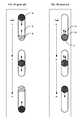
- FIG. 1Ais a representation of a moving target and the region through which the target moves.
- FIG. 1Bis a representation of the radiation reaching the area of FIG. 1A through an MLC aperture that is not optimized to take into account target motion.
- FIGS. 2A and 2Bshow time lapse representations of the un-optimized sliding window IMRT with apertures parallel to target movement.
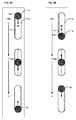
- FIG. 3is a representation of radiation reaching the area of FIG. 1A through an MLC aperture according to an embodiment of the present invention.
- FIGS. 4A and 4Bshow time lapse representations of sliding window IMRT according to an embodiment of the present invention.
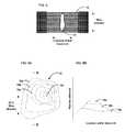
- FIG. 5is a representation of an MLC showing the leaves forming an aperture.
- FIGS. 6A and 6Bare a topographical visualization of a hypothetical fluence map delivered to a target region ( 6 A) and along one slice in that region ( 6 B).
- FIG. 7is a representation of a target region having optimized fluence.
- Radiation therapybegins with the development of a treatment plan for delivering a prescribed dose of radiation to a tumor while minimizing the dose of radiation delivered to surrounding tissue.
- the treatment planprescribes the amount of fluence each portion of target region should receive, but there are many leaf sequences (i.e., many combinations of leaf movements) that can be used to produce a given fluence.
- treatment planstypically provide for irradiating the target from multiple angles.
- treatment planninghas proceeded on the basis that the treatment volume is stationary while the patient is being irradiated, i.e., target motion was not taken into consideration.
- prior art treatment planningmade no effort to optimize leaf movements in relation to target motion.
- the present inventionis directed to the problem which arises when the treatment volume moves while being irradiated.
- the present inventionaddresses the problem by taking into account the interplay effects between leaf movements and target movements, as discussed herein.
- the treatment volumemay move in a periodic fashion along a trajectory.
- the trajectory of motionis modeled as a single path, even if there is some variation in the actual motion.
- the trajectory of any point in the treatment areacan reasonably be approximated by a line segment, although the present invention is not limited to motion along linear trajectories.
- This trajectorycan be projected onto the MLC plane, which is the plane is defined by the face of the MLC closest to the patient. This MLC plane is substantially orthogonal to the center of the radiation beam.
- FIG. 1Ashows a “snapshot” of a portion of a treatment area 4 that moves (sometimes referred to herein as a moving target).
- Area 4may be thought of as a tumor or portion of a tumor which is prescribed to receive a certain fractional dose of radiation.
- the area surrounding target 4may be, for example, a different region of the tumor for which a different fractional dose is prescribed.
- Motion of the moving target 4 along a trajectorydefines a larger region 2 through which the target moves in a periodic manner. Such motion may be caused, for example, by respiration.
- the trajectoryis a line segment.
- Use of a linear trajectoryis simple and convenient, and provides most of the advantages of the present invention when applied to actual treatment cases. More generally the trajectory can be curved, as discussed in further detail below.
- FIG. 1Bis a “snapshot” representation of the radiation beam 8 projected onto a portion of region 2 through an aperture in an MLC created by opposing leaf pairs.
- radiation beam 8may move in a direction that is parallel to the trajectory of the moving target (as indicated by the arrow).
- the MLC apertureis orthogonal to the trajectory of target motion.
- the movement of radiation beam 8can be in connection with either a sliding window IMRT technique or a point and shoot technique.
- FIGS. 2A and 2Billustrate in further detail the interplay effects in an un-optimized sliding window IMRT system.
- Both figuresshow a target 4 moving within region 2 along a trajectory, where the sliding window aperture, and hence radiation beam 8 , moves at approximately the same rate.
- direction of movement of beam 8is generally parallel to the direction of movement of the target 4 and in both figures beam 8 moves from bottom to top.
- FIG. 2Ashows three positions of target 4 and the radiation beam 8 as they move through area 2 , indicated by time markers t 1 , t 2 and t 3 .
- t 1 , t 2 and t 3In FIG.
- FIG. 2Bshows three positions of the target 4 as both it and beam 8 move from bottom to top at the same speed.
- the motions of target 4 and beam 8are “in phase” with one another.
- the movement shown in FIG. 2Bresults in the continued overlap of beam 8 with target 4 throughout the entire time radiation is delivered to area 2 .
- Thisprovides a dose that is much greater than the prescribed dose. Indeed, in the situation depicted in FIG. 2B , the dose is several times the prescribed dose.
- FIGS. 2A and 2Bexaggerate the interplay effect due to the fact that the target and beam move at substantially the same speed.
- the phasei.e., the starting position of the target relative to the beam, critical. Nonetheless, those skilled in the art will understand that the problem of interplay effects due to target motion will cause unoptimized results in many other circumstances.
- FIG. 3shows a radiation beam 10 reaching area 2 through an MLC aperture that extends parallel with and moves perpendicularly to the trajectory that defines region 2 . (Region 2 in FIG. 3 is the same as in FIGS. 1A , 1 B, 2 A and 2 B.)
- FIGS. 4A and 4Bare similar to FIGS. 2A and 2B , showing the same target 4 movement at times t 1 , t 2 and t 3 ; however, they illustrate an optimized sliding window IMRT according to an embodiment of the present invention, wherein the beam motion and target motion are orthogonal.
- FIG. 4Aas target 4 moves from top to bottom in region 2 , beam 10 moves across the region from left to right from time t 1 to t 3 .
- the movement of the beam(and hence the MLC slice or aperture) is orthogonal to the target trajectory.
- at all times throughout the delivery periodat least some portion (e.g., 12 a , 12 b , 12 c ) of the target 4 is receiving radiation.
- FIG. 5shows an exemplary MLC plane having a plurality of leaves 16 , arranged in opposing pairs, and an aperture 15 created by selected leaf movements, in well known fashion. Radiation passes through and is shaped by aperture 15 to create beam 10 .
- aperture 15is moved continuously (sliding window) or periodically (point and shoot) across the face of the MLC in either of the directions indicated in FIG. 5 .
- the apertureis moved its shape may be adjusted to control the fluence to different portions of the treatment volume, i.e., the combined leaf movements may be used, in known fashion, to vary the fluence delivered to the treatment area.
- An embodiment of the present inventionuses leaf sequences wherein the beam through the MLC aperture is generally parallel to the motion of target 4 and substantially equal to the length of region 2 . As beam 10 moves, the configuration of aperture 15 , may be adjusted, thereby allowing additional control over the fluence delivered to the treatment area.
- FIG. 6Adepicts the fluence delivered to a treatment field in the form of a topographical fluence map 20 , in accordance with an illustrative embodiment of the present invention.
- the lowest fluence represented in the mapis in the generally annular region 18 a , and the fluence increases to a maximum fluence region 18 n .
- FIG. 6Bshows the fluence received in the portion of the treatment area through the slice B-B of FIG. 6A .
- Slice B-Bis aligned with the trajectory of movement. All of the points along slice B-B will receive a fluence that is between the lowest fluence 18 a and a middle fluence 18 c .
- the slicesare aligned with the trajectory of the target's motion, thus even if a point in slice B-B were moving, it would not receive a higher fluence than the maximum for its slice, the middle fluence 18 c . Accordingly, the present technique has limited the range over which the delivered dose may vary.
- the MLC leaf movements of the present inventioncan be achieved with an algorithm similar to the one described in the co-assigned application entitled “Leaf Sequencing Algorithm To Reduce Tongue And Groove Effects” (U.S. patent application Ser. No. 12/267,044, now U.S. Pat. No. 7,609,811), the disclosure of which is incorporated by reference.
- the leaf sequenceis optimized to produce the field of radiation delivery for a moving target that more closely matches the intended dose.
- the leavesmay most easily be oriented to move perpendicularly to that movement, but other orientations are possible.
- the leaf motionneed not be oriented in the same direction as the movement of the aperture, although such orientation may simplify planning.
- the angle between the elongate apertures formed in the MLC and the trajectoryis minimized.
- the leaf movementmay be perpendicular to the tumor movement (as shown in FIG. 5 ), allowing the leaves to modulate the fluence in all positions in one slice relatively quickly.
- the orientation of the leavesis chosen based on the longest direction of the target field, such that they move perpendicularly to that direction as has been described.
- deciding on the orientation of the leavesis also influenced by the shape of the apertures that need to be formed in view of the shape of the tumor undergoing treatment. This is because some shapes present greater difficulties and can only be formed by a limited number of leaf arrangements.
- the optimizationis fine-tuned by controlling the time each movement slice is exposed to radiation through the aperture. For example, if each slice intersects with the open aperture for about the duration of one movement cycle, the dose distribution is closer to the planned average distribution.
- a variable dose ratecould be used to better control the exposure time for groups of slices. While timing the dose in this way is effective in conjunction with the present invention, and timing or gating in general is useful in a variety of applications, timing alone is not sufficient to avoid the interplay effects in an un-optimized system. Due to the periodic nature of the target movement and the difficulties in determining the precise location of the target 4 within region 2 at any given time, it is not practical to attempt to avoid phase problems, such as the overlapping situation shown in FIG. 3B , by simply timing the dose.
- the trajectory of the target regionmay be curved.
- the trajectoryis not a simple line segment, but is curved or has some other shape, additional considerations must be taken into account in order to determine the proper orientation for the aperture and the related optimized leaf sequence.
- the best technique for handling a curved trajectorywill depend on the exact shape and other aspects of the system, such as the physical constraints on leaf movement. In some cases, it may be sufficiently accurate and most efficient to simply map the trajectory to a predominant direction—a major axis of the trajectory curve, for example. In other cases, a rigid translation can be used to reduce the trajectories to a single direction, again, such as a predominant direction. This approach might be particularly useful for multiple, non-linear trajectories.
- the trajectoryis more complex, it can be obtained from deformable image registration, in which imaging is used to find a best fit. There, features of the target region are matched in order to align the trajectory with a template image. With other complex trajectories, a point-specific movement model might be used to identify the trajectory, such as the use of boundary conditions to model the target region. Once the trajectory has been obtained, if necessary, the trajectory can be mapped or translated into a predominant direction as discussed above.
- region 2may include healthy tissue which will be irradiated by the same dose as target 4 . While this is not the most desirable situation, in many situations it is more important to ensure an adequate and even dose to the target 4 than to avoid irradiating the surrounding tissue. In this regard, it should be noted that this unnecessary irradiation of portions of region 2 also occurs using the un-optimized system. For example, in FIG.
- the present inventionprovides an improved method for delivering radiation to a moving target, but further improvements to reduce the unnecessary radiation delivered to regions in the trajectory of the target would be beneficial.
Landscapes
- Health & Medical Sciences (AREA)
- Engineering & Computer Science (AREA)
- Biomedical Technology (AREA)
- Physics & Mathematics (AREA)
- General Health & Medical Sciences (AREA)
- Radiology & Medical Imaging (AREA)
- Life Sciences & Earth Sciences (AREA)
- Animal Behavior & Ethology (AREA)
- Nuclear Medicine, Radiotherapy & Molecular Imaging (AREA)
- Public Health (AREA)
- Veterinary Medicine (AREA)
- Pathology (AREA)
- Spectroscopy & Molecular Physics (AREA)
- General Engineering & Computer Science (AREA)
- High Energy & Nuclear Physics (AREA)
- Radiation-Therapy Devices (AREA)
Abstract
Description
Claims (20)
Priority Applications (1)
| Application Number | Priority Date | Filing Date | Title |
|---|---|---|---|
| US12/196,639US7796731B2 (en) | 2008-08-22 | 2008-08-22 | Leaf sequencing algorithm for moving targets |
Applications Claiming Priority (1)
| Application Number | Priority Date | Filing Date | Title |
|---|---|---|---|
| US12/196,639US7796731B2 (en) | 2008-08-22 | 2008-08-22 | Leaf sequencing algorithm for moving targets |
Publications (2)
| Publication Number | Publication Date |
|---|---|
| US20100046713A1 US20100046713A1 (en) | 2010-02-25 |
| US7796731B2true US7796731B2 (en) | 2010-09-14 |
Family
ID=41696402
Family Applications (1)
| Application Number | Title | Priority Date | Filing Date |
|---|---|---|---|
| US12/196,639ActiveUS7796731B2 (en) | 2008-08-22 | 2008-08-22 | Leaf sequencing algorithm for moving targets |
Country Status (1)
| Country | Link |
|---|---|
| US (1) | US7796731B2 (en) |
Cited By (32)
| Publication number | Priority date | Publication date | Assignee | Title |
|---|---|---|---|---|
| US20100108903A1 (en)* | 2007-03-23 | 2010-05-06 | Christoph Bert | Determination of control parameters for irradiation of a moving target volume in a body |
| US20110200170A1 (en)* | 2010-02-18 | 2011-08-18 | Varian Medical Systems International Ag | Method and System for Treating Moving Target |
| US8344340B2 (en) | 2005-11-18 | 2013-01-01 | Mevion Medical Systems, Inc. | Inner gantry |
| US8581523B2 (en) | 2007-11-30 | 2013-11-12 | Mevion Medical Systems, Inc. | Interrupted particle source |
| US8791656B1 (en) | 2013-05-31 | 2014-07-29 | Mevion Medical Systems, Inc. | Active return system |
| US8927950B2 (en) | 2012-09-28 | 2015-01-06 | Mevion Medical Systems, Inc. | Focusing a particle beam |
| US8933650B2 (en) | 2007-11-30 | 2015-01-13 | Mevion Medical Systems, Inc. | Matching a resonant frequency of a resonant cavity to a frequency of an input voltage |
| US8952634B2 (en) | 2004-07-21 | 2015-02-10 | Mevion Medical Systems, Inc. | Programmable radio frequency waveform generator for a synchrocyclotron |
| US9155186B2 (en) | 2012-09-28 | 2015-10-06 | Mevion Medical Systems, Inc. | Focusing a particle beam using magnetic field flutter |
| US9185789B2 (en) | 2012-09-28 | 2015-11-10 | Mevion Medical Systems, Inc. | Magnetic shims to alter magnetic fields |
| US9301384B2 (en) | 2012-09-28 | 2016-03-29 | Mevion Medical Systems, Inc. | Adjusting energy of a particle beam |
| US9545528B2 (en) | 2012-09-28 | 2017-01-17 | Mevion Medical Systems, Inc. | Controlling particle therapy |
| US9622335B2 (en) | 2012-09-28 | 2017-04-11 | Mevion Medical Systems, Inc. | Magnetic field regenerator |
| US9661736B2 (en) | 2014-02-20 | 2017-05-23 | Mevion Medical Systems, Inc. | Scanning system for a particle therapy system |
| US9681531B2 (en) | 2012-09-28 | 2017-06-13 | Mevion Medical Systems, Inc. | Control system for a particle accelerator |
| US9723705B2 (en) | 2012-09-28 | 2017-08-01 | Mevion Medical Systems, Inc. | Controlling intensity of a particle beam |
| US9730308B2 (en) | 2013-06-12 | 2017-08-08 | Mevion Medical Systems, Inc. | Particle accelerator that produces charged particles having variable energies |
| US9827445B2 (en) | 2013-09-27 | 2017-11-28 | Varian Medical Systems International Ag | Automatic creation and selection of dose prediction models for treatment plans |
| US9950194B2 (en) | 2014-09-09 | 2018-04-24 | Mevion Medical Systems, Inc. | Patient positioning system |
| US9962560B2 (en) | 2013-12-20 | 2018-05-08 | Mevion Medical Systems, Inc. | Collimator and energy degrader |
| US10254739B2 (en) | 2012-09-28 | 2019-04-09 | Mevion Medical Systems, Inc. | Coil positioning system |
| US10258810B2 (en) | 2013-09-27 | 2019-04-16 | Mevion Medical Systems, Inc. | Particle beam scanning |
| US10646728B2 (en) | 2015-11-10 | 2020-05-12 | Mevion Medical Systems, Inc. | Adaptive aperture |
| US10653892B2 (en) | 2017-06-30 | 2020-05-19 | Mevion Medical Systems, Inc. | Configurable collimator controlled using linear motors |
| US10675487B2 (en) | 2013-12-20 | 2020-06-09 | Mevion Medical Systems, Inc. | Energy degrader enabling high-speed energy switching |
| US10709905B2 (en)* | 2018-06-29 | 2020-07-14 | Victor Hernandez | Method of calculating a tongue-and-groove effect of a multi-leaf collimator |
| US10762167B2 (en) | 2013-09-27 | 2020-09-01 | Varian Medical Systems International Ag | Decision support tool for choosing treatment plans |
| WO2020200849A1 (en) | 2019-03-29 | 2020-10-08 | Varian Medical Systems International Ag | Using isodose surfaces for optimizing dose distribution in radiation treatment planning |
| US10925147B2 (en) | 2016-07-08 | 2021-02-16 | Mevion Medical Systems, Inc. | Treatment planning |
| US11103730B2 (en) | 2017-02-23 | 2021-08-31 | Mevion Medical Systems, Inc. | Automated treatment in particle therapy |
| US11291861B2 (en) | 2019-03-08 | 2022-04-05 | Mevion Medical Systems, Inc. | Delivery of radiation by column and generating a treatment plan therefor |
| US20230132237A1 (en)* | 2020-06-08 | 2023-04-27 | Suzhou Linatech Medical Science And Technology Co., Ltd. | An orthogonal double-layer grating dynamic intensity modulation segmentation method based on quadrant |
Families Citing this family (6)
| Publication number | Priority date | Publication date | Assignee | Title |
|---|---|---|---|---|
| US20120002780A1 (en)* | 2009-03-25 | 2012-01-05 | Koninklijke Philips Electronics N.V. | Method and apparatus for breathing adapted imaging |
| WO2011005329A2 (en) | 2009-07-09 | 2011-01-13 | The Board Of Trustees Of The Leland Stanford Junior University | Method and system for real-time dmlc-based target tracking with optimal motion compensating leaf adaptation |
| JP5848573B2 (en)* | 2011-10-04 | 2016-01-27 | 株式会社日立製作所 | Moving body tracking radiotherapy system |
| US10729920B2 (en)* | 2015-10-02 | 2020-08-04 | Varian Medical Systems International Ag | Systems and methods for quantifying radiation beam conformity |
| US9999787B1 (en)* | 2017-03-08 | 2018-06-19 | Varian Medical Systems International Ag. | Beam limiting device for intensity modulated proton therapy |
| CN112043974B (en)* | 2020-09-08 | 2021-07-06 | 苏州雷泰医疗科技有限公司 | A Dynamic Intensity Modulation Method and Device Based on Orthogonal Double Layer Grating Rotation Sweep |
Citations (13)
| Publication number | Priority date | Publication date | Assignee | Title |
|---|---|---|---|---|
| US6144875A (en)* | 1999-03-16 | 2000-11-07 | Accuray Incorporated | Apparatus and method for compensating for respiratory and patient motion during treatment |
| US6307914B1 (en)* | 1998-03-12 | 2001-10-23 | Mitsubishi Denki Kabushiki Kaisha | Moving body pursuit irradiating device and positioning method using this device |
| US6757355B1 (en)* | 2000-08-17 | 2004-06-29 | Siemens Medical Solutions Usa, Inc. | High definition radiation treatment with an intensity modulating multi-leaf collimator |
| US6907105B2 (en)* | 2001-09-25 | 2005-06-14 | Bc Cancer Agency | Methods and apparatus for planning and delivering intensity modulated radiation fields with a rotating multileaf collimator |
| US7020245B2 (en)* | 2003-03-13 | 2006-03-28 | Kabushiki Kaisha Toshiba | Multileaf collimator |
| US20070076846A1 (en)* | 2005-07-22 | 2007-04-05 | Ruchala Kenneth J | System and method of delivering radiation therapy to a moving region of interest |
| US7221733B1 (en)* | 2002-01-02 | 2007-05-22 | Varian Medical Systems Technologies, Inc. | Method and apparatus for irradiating a target |
| US20070201613A1 (en)* | 2005-07-22 | 2007-08-30 | Weiguo Lu | System and method of detecting a breathing phase of a patient receiving radiation therapy |
| US20080144772A1 (en)* | 2006-12-14 | 2008-06-19 | Byong Yong Yi | Treatment-Speed Regulated Tumor-Tracking |
| US20080159478A1 (en)* | 2006-12-11 | 2008-07-03 | Keall Paul J | Method to track three-dimensional target motion with a dynamical multi-leaf collimator |
| US20080298550A1 (en)* | 2005-07-25 | 2008-12-04 | Karl Otto | Methods and apparatus for the planning and delivery of radiation treatments |
| US7507975B2 (en)* | 2006-04-21 | 2009-03-24 | Varian Medical Systems, Inc. | System and method for high resolution radiation field shaping |
| US7551717B2 (en)* | 2007-08-21 | 2009-06-23 | Wisconsin Alumni Research Foundation | Virtual 4D treatment suite |
- 2008
- 2008-08-22USUS12/196,639patent/US7796731B2/enactiveActive
Patent Citations (13)
| Publication number | Priority date | Publication date | Assignee | Title |
|---|---|---|---|---|
| US6307914B1 (en)* | 1998-03-12 | 2001-10-23 | Mitsubishi Denki Kabushiki Kaisha | Moving body pursuit irradiating device and positioning method using this device |
| US6144875A (en)* | 1999-03-16 | 2000-11-07 | Accuray Incorporated | Apparatus and method for compensating for respiratory and patient motion during treatment |
| US6757355B1 (en)* | 2000-08-17 | 2004-06-29 | Siemens Medical Solutions Usa, Inc. | High definition radiation treatment with an intensity modulating multi-leaf collimator |
| US6907105B2 (en)* | 2001-09-25 | 2005-06-14 | Bc Cancer Agency | Methods and apparatus for planning and delivering intensity modulated radiation fields with a rotating multileaf collimator |
| US7221733B1 (en)* | 2002-01-02 | 2007-05-22 | Varian Medical Systems Technologies, Inc. | Method and apparatus for irradiating a target |
| US7020245B2 (en)* | 2003-03-13 | 2006-03-28 | Kabushiki Kaisha Toshiba | Multileaf collimator |
| US20070076846A1 (en)* | 2005-07-22 | 2007-04-05 | Ruchala Kenneth J | System and method of delivering radiation therapy to a moving region of interest |
| US20070201613A1 (en)* | 2005-07-22 | 2007-08-30 | Weiguo Lu | System and method of detecting a breathing phase of a patient receiving radiation therapy |
| US20080298550A1 (en)* | 2005-07-25 | 2008-12-04 | Karl Otto | Methods and apparatus for the planning and delivery of radiation treatments |
| US7507975B2 (en)* | 2006-04-21 | 2009-03-24 | Varian Medical Systems, Inc. | System and method for high resolution radiation field shaping |
| US20080159478A1 (en)* | 2006-12-11 | 2008-07-03 | Keall Paul J | Method to track three-dimensional target motion with a dynamical multi-leaf collimator |
| US20080144772A1 (en)* | 2006-12-14 | 2008-06-19 | Byong Yong Yi | Treatment-Speed Regulated Tumor-Tracking |
| US7551717B2 (en)* | 2007-08-21 | 2009-06-23 | Wisconsin Alumni Research Foundation | Virtual 4D treatment suite |
Non-Patent Citations (1)
| Title |
|---|
| Murphy, Martin J., Tracking Moving Organs in Real Time, Jan. 2004, Seminars in Radiation Oncology, Stanford University, vol. 14, No. 1, pp. 91-100.* |
Cited By (53)
| Publication number | Priority date | Publication date | Assignee | Title |
|---|---|---|---|---|
| US8952634B2 (en) | 2004-07-21 | 2015-02-10 | Mevion Medical Systems, Inc. | Programmable radio frequency waveform generator for a synchrocyclotron |
| USRE48047E1 (en) | 2004-07-21 | 2020-06-09 | Mevion Medical Systems, Inc. | Programmable radio frequency waveform generator for a synchrocyclotron |
| US8344340B2 (en) | 2005-11-18 | 2013-01-01 | Mevion Medical Systems, Inc. | Inner gantry |
| US8907311B2 (en) | 2005-11-18 | 2014-12-09 | Mevion Medical Systems, Inc. | Charged particle radiation therapy |
| US8299448B2 (en)* | 2007-03-23 | 2012-10-30 | Gsi Helmholtzzentrum Fuer Schwerionenforschung Gmbh | Determination of control parameters for irradiation of a moving target volume in a body |
| US20100108903A1 (en)* | 2007-03-23 | 2010-05-06 | Christoph Bert | Determination of control parameters for irradiation of a moving target volume in a body |
| US8933650B2 (en) | 2007-11-30 | 2015-01-13 | Mevion Medical Systems, Inc. | Matching a resonant frequency of a resonant cavity to a frequency of an input voltage |
| US8970137B2 (en) | 2007-11-30 | 2015-03-03 | Mevion Medical Systems, Inc. | Interrupted particle source |
| US8581523B2 (en) | 2007-11-30 | 2013-11-12 | Mevion Medical Systems, Inc. | Interrupted particle source |
| USRE48317E1 (en) | 2007-11-30 | 2020-11-17 | Mevion Medical Systems, Inc. | Interrupted particle source |
| US8331532B2 (en)* | 2010-02-18 | 2012-12-11 | Varian Medical Systems International Ag | Method and system for treating moving target |
| US8744045B2 (en) | 2010-02-18 | 2014-06-03 | Varian Medical Systems International Ag | Method and system for treating moving target |
| US20110200170A1 (en)* | 2010-02-18 | 2011-08-18 | Varian Medical Systems International Ag | Method and System for Treating Moving Target |
| US10254739B2 (en) | 2012-09-28 | 2019-04-09 | Mevion Medical Systems, Inc. | Coil positioning system |
| US10368429B2 (en) | 2012-09-28 | 2019-07-30 | Mevion Medical Systems, Inc. | Magnetic field regenerator |
| US9301384B2 (en) | 2012-09-28 | 2016-03-29 | Mevion Medical Systems, Inc. | Adjusting energy of a particle beam |
| US9545528B2 (en) | 2012-09-28 | 2017-01-17 | Mevion Medical Systems, Inc. | Controlling particle therapy |
| US9622335B2 (en) | 2012-09-28 | 2017-04-11 | Mevion Medical Systems, Inc. | Magnetic field regenerator |
| US8927950B2 (en) | 2012-09-28 | 2015-01-06 | Mevion Medical Systems, Inc. | Focusing a particle beam |
| US9681531B2 (en) | 2012-09-28 | 2017-06-13 | Mevion Medical Systems, Inc. | Control system for a particle accelerator |
| US9706636B2 (en) | 2012-09-28 | 2017-07-11 | Mevion Medical Systems, Inc. | Adjusting energy of a particle beam |
| US9723705B2 (en) | 2012-09-28 | 2017-08-01 | Mevion Medical Systems, Inc. | Controlling intensity of a particle beam |
| US9185789B2 (en) | 2012-09-28 | 2015-11-10 | Mevion Medical Systems, Inc. | Magnetic shims to alter magnetic fields |
| US9155186B2 (en) | 2012-09-28 | 2015-10-06 | Mevion Medical Systems, Inc. | Focusing a particle beam using magnetic field flutter |
| US10155124B2 (en) | 2012-09-28 | 2018-12-18 | Mevion Medical Systems, Inc. | Controlling particle therapy |
| US8791656B1 (en) | 2013-05-31 | 2014-07-29 | Mevion Medical Systems, Inc. | Active return system |
| US9730308B2 (en) | 2013-06-12 | 2017-08-08 | Mevion Medical Systems, Inc. | Particle accelerator that produces charged particles having variable energies |
| US9827445B2 (en) | 2013-09-27 | 2017-11-28 | Varian Medical Systems International Ag | Automatic creation and selection of dose prediction models for treatment plans |
| US10258810B2 (en) | 2013-09-27 | 2019-04-16 | Mevion Medical Systems, Inc. | Particle beam scanning |
| US10762167B2 (en) | 2013-09-27 | 2020-09-01 | Varian Medical Systems International Ag | Decision support tool for choosing treatment plans |
| US10456591B2 (en) | 2013-09-27 | 2019-10-29 | Mevion Medical Systems, Inc. | Particle beam scanning |
| US9962560B2 (en) | 2013-12-20 | 2018-05-08 | Mevion Medical Systems, Inc. | Collimator and energy degrader |
| US10675487B2 (en) | 2013-12-20 | 2020-06-09 | Mevion Medical Systems, Inc. | Energy degrader enabling high-speed energy switching |
| US10434331B2 (en) | 2014-02-20 | 2019-10-08 | Mevion Medical Systems, Inc. | Scanning system |
| US11717700B2 (en) | 2014-02-20 | 2023-08-08 | Mevion Medical Systems, Inc. | Scanning system |
| US9661736B2 (en) | 2014-02-20 | 2017-05-23 | Mevion Medical Systems, Inc. | Scanning system for a particle therapy system |
| US9950194B2 (en) | 2014-09-09 | 2018-04-24 | Mevion Medical Systems, Inc. | Patient positioning system |
| US10646728B2 (en) | 2015-11-10 | 2020-05-12 | Mevion Medical Systems, Inc. | Adaptive aperture |
| US11213697B2 (en) | 2015-11-10 | 2022-01-04 | Mevion Medical Systems, Inc. | Adaptive aperture |
| US10786689B2 (en) | 2015-11-10 | 2020-09-29 | Mevion Medical Systems, Inc. | Adaptive aperture |
| US11786754B2 (en) | 2015-11-10 | 2023-10-17 | Mevion Medical Systems, Inc. | Adaptive aperture |
| US12150235B2 (en) | 2016-07-08 | 2024-11-19 | Mevion Medical Systems, Inc. | Treatment planning |
| US10925147B2 (en) | 2016-07-08 | 2021-02-16 | Mevion Medical Systems, Inc. | Treatment planning |
| US11103730B2 (en) | 2017-02-23 | 2021-08-31 | Mevion Medical Systems, Inc. | Automated treatment in particle therapy |
| US10653892B2 (en) | 2017-06-30 | 2020-05-19 | Mevion Medical Systems, Inc. | Configurable collimator controlled using linear motors |
| US10709905B2 (en)* | 2018-06-29 | 2020-07-14 | Victor Hernandez | Method of calculating a tongue-and-groove effect of a multi-leaf collimator |
| US11291861B2 (en) | 2019-03-08 | 2022-04-05 | Mevion Medical Systems, Inc. | Delivery of radiation by column and generating a treatment plan therefor |
| US11717703B2 (en) | 2019-03-08 | 2023-08-08 | Mevion Medical Systems, Inc. | Delivery of radiation by column and generating a treatment plan therefor |
| US12161885B2 (en) | 2019-03-08 | 2024-12-10 | Mevion Medical Systems, Inc. | Delivery of radiation by column and generating a treatment plan therefor |
| US12168147B2 (en) | 2019-03-08 | 2024-12-17 | Mevion Medical Systems, Inc. | Collimator and energy degrader for a particle therapy system |
| WO2020200849A1 (en) | 2019-03-29 | 2020-10-08 | Varian Medical Systems International Ag | Using isodose surfaces for optimizing dose distribution in radiation treatment planning |
| US20230132237A1 (en)* | 2020-06-08 | 2023-04-27 | Suzhou Linatech Medical Science And Technology Co., Ltd. | An orthogonal double-layer grating dynamic intensity modulation segmentation method based on quadrant |
| US12226656B2 (en)* | 2020-06-08 | 2025-02-18 | Suzhou Linatech Medical Science And Technology Co., Ltd. | Orthogonal double-layer grating dynamic intensity modulation segmentation method based on quadrant |
Also Published As
| Publication number | Publication date |
|---|---|
| US20100046713A1 (en) | 2010-02-25 |
Similar Documents
| Publication | Publication Date | Title |
|---|---|---|
| US7796731B2 (en) | Leaf sequencing algorithm for moving targets | |
| US8331532B2 (en) | Method and system for treating moving target | |
| EP3436150B1 (en) | Radiation therapy systems | |
| US7609810B2 (en) | Treatment-speed regulated tumor-tracking | |
| EP2280765B1 (en) | Treatment of patient tumors by charged particle therapy | |
| US7295649B2 (en) | Radiation therapy system and method of using the same | |
| US8613694B2 (en) | Method for biological modulation of radiation therapy | |
| US7977657B2 (en) | Ion radiation therapy system with distal gradient tracking | |
| US20090189095A1 (en) | Ion radiation therapy system with variable beam resolution | |
| US20080049897A1 (en) | System and Method for Temporally Precise Intensity Modulated Radiation Therapy (Imrt) | |
| JP7735363B2 (en) | System for delivering proton therapy using cyclical motion | |
| US20190168025A1 (en) | Image-guided radiation therapy | |
| US20210046330A1 (en) | Particle beam guiding system and related radiotherapy system | |
| US9597529B2 (en) | Rapid range stacking (RRS) for particle beam therapy | |
| US10828514B2 (en) | Radiotherapy system preventing radiation of health tissue | |
| Flanz | Particle beam scanning | |
| Woźniak et al. | Dynamic-arc respiratory-gated stereotactic radiotherapy—technique presentation | |
| Chan | Evaluation of dosimetric performance and respiration motion tracking accuracy on Radixact® System with Synchrony® for real patients | |
| Maradia et al. | High-speed proton therapy within a short breath-hold | |
| HK1260433B (en) | Radiation therapy systems |
Legal Events
| Date | Code | Title | Description |
|---|---|---|---|
| AS | Assignment | Owner name:VARIAN MEDICAL SYSTEMS INTERNATIONAL AG,SWITZERLAN Free format text:ASSIGNMENT OF ASSIGNORS INTEREST;ASSIGNORS:NORD, JANNE ILMARI;SILJAMAKI, SAMI PEKKA;TORSTI, TUOMAS ERIK;REEL/FRAME:021438/0370 Effective date:20080821 Owner name:VARIAN MEDICAL SYSTEMS INTERNATIONAL AG, SWITZERLA Free format text:ASSIGNMENT OF ASSIGNORS INTEREST;ASSIGNORS:NORD, JANNE ILMARI;SILJAMAKI, SAMI PEKKA;TORSTI, TUOMAS ERIK;REEL/FRAME:021438/0370 Effective date:20080821 | |
| STCF | Information on status: patent grant | Free format text:PATENTED CASE | |
| FPAY | Fee payment | Year of fee payment:4 | |
| MAFP | Maintenance fee payment | Free format text:PAYMENT OF MAINTENANCE FEE, 8TH YEAR, LARGE ENTITY (ORIGINAL EVENT CODE: M1552) Year of fee payment:8 | |
| MAFP | Maintenance fee payment | Free format text:PAYMENT OF MAINTENANCE FEE, 12TH YEAR, LARGE ENTITY (ORIGINAL EVENT CODE: M1553); ENTITY STATUS OF PATENT OWNER: LARGE ENTITY Year of fee payment:12 | |
| AS | Assignment | Owner name:SIEMENS HEALTHINEERS INTERNATIONAL AG, SWITZERLAND Free format text:CHANGE OF NAME;ASSIGNOR:VARIAN MEDICAL SYSTEMS INTERNATIONAL AG;REEL/FRAME:066340/0555 Effective date:20220414 |