US7796251B2 - Method, apparatus and system for rapid and sensitive standoff detection of surface contaminants - Google Patents
Method, apparatus and system for rapid and sensitive standoff detection of surface contaminantsDownload PDFInfo
- Publication number
- US7796251B2 US7796251B2US11/688,434US68843407AUS7796251B2US 7796251 B2US7796251 B2US 7796251B2US 68843407 AUS68843407 AUS 68843407AUS 7796251 B2US7796251 B2US 7796251B2
- Authority
- US
- United States
- Prior art keywords
- unit
- scattered radiation
- light
- spectral data
- spectrograph
- Prior art date
- Legal status (The legal status is an assumption and is not a legal conclusion. Google has not performed a legal analysis and makes no representation as to the accuracy of the status listed.)
- Active, expires
Links
Images


Classifications
- G—PHYSICS
- G01—MEASURING; TESTING
- G01N—INVESTIGATING OR ANALYSING MATERIALS BY DETERMINING THEIR CHEMICAL OR PHYSICAL PROPERTIES
- G01N21/00—Investigating or analysing materials by the use of optical means, i.e. using sub-millimetre waves, infrared, visible or ultraviolet light
- G01N21/62—Systems in which the material investigated is excited whereby it emits light or causes a change in wavelength of the incident light
- G01N21/63—Systems in which the material investigated is excited whereby it emits light or causes a change in wavelength of the incident light optically excited
- G01N21/65—Raman scattering
- G—PHYSICS
- G01—MEASURING; TESTING
- G01J—MEASUREMENT OF INTENSITY, VELOCITY, SPECTRAL CONTENT, POLARISATION, PHASE OR PULSE CHARACTERISTICS OF INFRARED, VISIBLE OR ULTRAVIOLET LIGHT; COLORIMETRY; RADIATION PYROMETRY
- G01J3/00—Spectrometry; Spectrophotometry; Monochromators; Measuring colours
- G01J3/02—Details
- G01J3/0205—Optical elements not provided otherwise, e.g. optical manifolds, diffusers, windows
- G01J3/0218—Optical elements not provided otherwise, e.g. optical manifolds, diffusers, windows using optical fibers
- G—PHYSICS
- G01—MEASURING; TESTING
- G01J—MEASUREMENT OF INTENSITY, VELOCITY, SPECTRAL CONTENT, POLARISATION, PHASE OR PULSE CHARACTERISTICS OF INFRARED, VISIBLE OR ULTRAVIOLET LIGHT; COLORIMETRY; RADIATION PYROMETRY
- G01J3/00—Spectrometry; Spectrophotometry; Monochromators; Measuring colours
- G01J3/02—Details
- G01J3/0272—Handheld
- G—PHYSICS
- G01—MEASURING; TESTING
- G01J—MEASUREMENT OF INTENSITY, VELOCITY, SPECTRAL CONTENT, POLARISATION, PHASE OR PULSE CHARACTERISTICS OF INFRARED, VISIBLE OR ULTRAVIOLET LIGHT; COLORIMETRY; RADIATION PYROMETRY
- G01J3/00—Spectrometry; Spectrophotometry; Monochromators; Measuring colours
- G01J3/02—Details
- G01J3/0291—Housings; Spectrometer accessories; Spatial arrangement of elements, e.g. folded path arrangements
- G—PHYSICS
- G01—MEASURING; TESTING
- G01J—MEASUREMENT OF INTENSITY, VELOCITY, SPECTRAL CONTENT, POLARISATION, PHASE OR PULSE CHARACTERISTICS OF INFRARED, VISIBLE OR ULTRAVIOLET LIGHT; COLORIMETRY; RADIATION PYROMETRY
- G01J3/00—Spectrometry; Spectrophotometry; Monochromators; Measuring colours
- G01J3/28—Investigating the spectrum
- G01J3/44—Raman spectrometry; Scattering spectrometry ; Fluorescence spectrometry
- G—PHYSICS
- G01—MEASURING; TESTING
- G01N—INVESTIGATING OR ANALYSING MATERIALS BY DETERMINING THEIR CHEMICAL OR PHYSICAL PROPERTIES
- G01N2201/00—Features of devices classified in G01N21/00
- G01N2201/02—Mechanical
- G01N2201/022—Casings
- G01N2201/0221—Portable; cableless; compact; hand-held
Definitions
- the present inventionrelates to applied ultraviolet (UV) Raman spectroscopy and chemical detection and identification. More specifically, the present invention relates to devices, systems and methods for remotely detecting hazardous substances that may be on a surface.
- UVultraviolet
- Spectroscopy techniquesare used to analyze substances and techniques have been developed for the non-destructive testing of surface-deposited substances in solid and liquid phases. Such techniques include Fourier Transform Infrared Spectroscopy (FTIR), X-ray fluorescence, gas chromatography and mass spectrometry (GC-MS), and Infrared Raman spectroscopy (IR Raman).
- FTIRFourier Transform Infrared Spectroscopy
- GC-MSgas chromatography and mass spectrometry
- IR RamanInfrared Raman spectroscopy
- FTIRFourier Transform Infrared Spectroscopy
- GC-MSgas chromatography and mass spectrometry
- IR RamanInfrared Raman spectroscopy
- Currently available surface-hazard detectorsare “point-and-shoot” devices, in which the device operator holds a sensing probe on a specific location at very close range and dwells on that specific location for an amount of time to provide sufficient integration time
- Surface contaminationcan be the result of an accident or intentional dispersion of the contaminant, and therefore the surface contamination can consist of a single chemical or multiple chemicals in bulk form or dispersed over a wide area.
- the surface contaminationcan consist of a single chemical or multiple chemicals in bulk form or dispersed over a wide area.
- none of the above mentioned methodsprovide adequate detection capabilities.
- FTIR system for emergency responserequires 20 seconds to carry out a single sample-identification analysis, while the sample needs to be physically removed from the surface and presented to the sensor.
- IR-Raman system for emergency responsethat requires a maximum distance of 15 mm and measurement times typically between 1 and 5 seconds with up to 20 seconds for some samples.
- UV Raman spectroscopyhas many unique properties that can be advantageously employed in the rapid standoff detection and identification of surface-deposited hazards.
- the high degree of information content inherent in Raman spectroscopyprovides the ability to differentiate structurally similar chemicals with low false alarm rates.
- the information contentis associated with the vibrational degrees of freedom associated with any molecule. This wealth of vibrational modes manifests itself in rich, narrow Raman peaks that provide a spectral fingerprint for a given Raman active material.
- Spontaneous Raman scatteringhowever, has an intrinsically weak cross-section.
- the intensity and quality of the Raman spectrumdepends on (1) the wavelength, linewidth and spectral purity of the excitation light, (2) the extent to which the excitation or scattered light is absorbed, the amount of interfering fluorescence that is emitted, and the potential existence of interfering laser-induced breakdown emission of surface materials, (3) the thermal and photochemical stability of the sample under excitation, and (4) the number or chemicals simultaneously interrogated (spectral congestion).
- UV Raman sensorscapitalize on a short wavelength resulting in larger scattering cross-sections, a reduced natural fluorescence background (no photo-bleaching required), a solar-blind spectral region below 300 nm (important for a standoff sensor) and resonance enhancement of the Raman scattering cross-section for some vibrational transitions.
- UV light sources below 300-nmpresent virtually no eye hazard to personnel wearing standard plastic or non-crystalline glass eye-protection.
- a surface-hazard detection systemis needed that can safely interrogate surfaces from greater distances and that can do it with a high degree of flexibility in the adjustment of the sensor field of interest.
- This standoff surface-hazard detection systemneeds also to rapidly analyze returned optical radiation from the substance in order to provide the high data throughput that enables large perimeter searches.
- UV Raman spectroscopyprovides the foundation for this high performance sensor.
- the present inventionis directed to systems and methods for fast and sensitive standoff surface-hazard detection with high data throughput, high spatial resolution and high degree of pointing flexibility.
- the systemcomprises a first hand-held unit that directs an excitation beam onto a surface that is located a distance away from the first unit and an optical subsystem that captures scattered radiation from the surface as a result of the beam of light.
- the first unitis connected via a link that includes a bundle of optical fibers, to a second unit, called the processing unit.
- the processing unitcomprises a fiber-coupled spectrograph to convert scattered radiation to spectral data, and a processor that analyzes the collected signal and detect the hazardous substance.
- the second unitmay be contained within a body-wearable housing or apparatus so that the first unit and second unit together form a man-portable detection assembly.
- Adjustable focus collection opticscollect the Raman scattered radiation from safer distances, such as more than 0.25 m.
- a visible light spotmay be projected onto the surface to indicate the optimum standoff range and to indicate the location of the collection field of view.
- the system of the present inventionuses a UV-transmitting fiber bundle to efficiently couple the collected scattered radiation image to the spectrograph.
- a round multi-fiber bundleis positioned at the focal plane of telescope and fibers of the bundle are rearranged to form a single row that is used as the entrance slit of the spectrograph.
- the spectrographimages the entrance slit onto a pixelated light detector after the light is spatially dispersed by a grating.
- the system and method of the present inventionuses the pixelated light detector located at the output of the spectrograph to detect the Raman return.
- Several Raman returnscan be accumulated in order to improve the signal to noise ratio (SNR) of a given measurement frame.
- a configurable number of returnsare accumulated onto the detector to provide a single measurement frame, and each vertical column of pixels of the detector is binned to further improve the SNR.
- the resulting array of digital values extracted from the detectorcontains the Raman signature used by the processing unit to make a substance detection and identification.
- the number of Raman returns accumulated in each measurement frameis variable. For example, during rapid search, a surface is quickly scanned and fast frame rates (i.e.
- each frameis composed of short total exposures ensuring a higher probability of grabbing a high-purity Raman signature (low spectral congestion) from a target compound that is being encountered during scan.
- the short-exposure framesallow the sensor to cope with the quick sequence made of a large variety of surface substances presented to the sensor resulting from the rapid surface-scan.
- the senorduring a confirmation or identification mode, the sensor stares at the interrogated surface so that Raman signature have higher purity since less variety is presented to the sensor) and slower frame rates (more Raman-returns accumulations per frame) are important to provide high identification specificity by improving the Raman signature SNR.
- the system and method of the present inventionmay use a continuous scan of the surface to detect contamination patches.
- this sensor system of the present inventionallows for rapid surface scans that range from static to up to tens of centimeters per second depending on the scenario. This is possible since the sensor can output good quality Raman measurement frames at a 10 to 25 Hz rate while maintaining a practical standoff range (i.e., 1 m).
- the capability to generate these high frame ratesallows for capturing of Raman data in the form of “Raman-video” signal.
- a search modeis used to provide maximum scan speed while screening a large perimeter.
- the high data throughput associated with the search modeis compatible with adaptive sampling techniques that use the real-time results to direct and optimize a search and scanning strategy.
- the detection and identification system of the present inventionemploy a distributed architecture to maximize system-level performance.
- One unitmay be a battery-operated backpack or suitcase unit housing a scaled down version of beam directing, scattering collection and spectrum analysis into an agile configuration.
- a second unit, called a base station,contains processing capability for more intensive analysis of the collected spectra. Consequently, the battery-operated unit can be made lighter by carrying a small processing device that can execute a less computationally-intensive spectrum analysis algorithm.
- a plurality of surface scanning sensorsmay be deployed to scale a search effort in large areas or regions, or buildings. All of the sensors report detection events to a centralized scene-control unit that can coordinate the search effort.
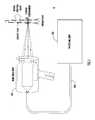
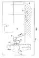
- FIG. 1is a graphical diagram of a standoff surface-hazard detection system according to one embodiment of the present invention.
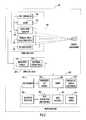
- FIG. 2is a block diagram of a standoff surface-hazard detection system according to one embodiment of the invention.
- FIG. 3is a block diagram of a standoff surface-hazard detection system according to an embodiment of the invention.
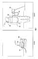
- FIGS. 4A , 4 B, 4 C and 4 Dillustrate several configurations of a hand-held device forming a part of the standoff surface-hazard detection system according to embodiments of the invention.
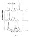
- FIG. 5illustrates plots for a single measurement frame of data derived from scanning a surface according to the embodiments of the present invention.
- FIG. 6is a perspective view of a standoff surface-hazard detection system according to an embodiment of the invention.
- FIG. 7is a diagram showing operation of the standoff hazard detection system according to the embodiment of the invention shown in FIG. 3 .
- FIG. 8is a diagram illustrating a use-scenario of the standoff hazard detection system for scanning various surfaces and searching contamination patches according to an embodiment of the invention.
- the detection system 10comprises a hand-held unit 100 and a processing unit 200 .
- the hand-held unit 100is also referred to herein as a first unit or a “wand” unit or device and the processing unit 200 is also referred to herein as a second unit or a data acquisition/processing unit.
- the hand-held unit 100is connected by an umbilical cable 300 to the processing unit 200 .
- standoffin connection with a standoff hazard detection and identification system means a distance or range of more than 0.25 meters between the detecting apparatus and the surface that is being interrogated and on which a hazardous substance or contaminant may reside.
- the system 10achieves fast and sensitive standoff surface-hazard detection with high data throughput, high spatial resolution and high degree of pointing flexibility. This distinctive mode of operation enables new, efficient, surface-contamination search strategies. In contrast to the existing “point-and-shoot” techniques, the system 10 enables acquiring single-pixel “Raman-video” footages of a contaminated scene as depicted in FIG. 1 .
- the hand-held unit 100is held in the hand of a user and is used to direct a light beam onto a surface to analyze with spectroscopy techniques a substance in solid or liquid phase on the surface in order to determine a composition of the substance.
- the substancemay be a hazardous substance or contaminant, such as a chemical, biological or explosive substance on the ground, floor, wall or other objects, and the substance may be present in bulk or sparsely dispersed over a surface.
- the system 10may be designed for use by one person or by a two-person team. The operators may be wearing hazard-protective gear.
- the hand-held unit 100is used to interrogate a suspected surface at a stand-off distance of approximately 0.5 to 3 meters, and to return spectrum related data about the threat to the processing unit 200 that analyzes the spectrum related data in direct line of sight, determines whether there is a presence of a harmful threat, and rapidly issues a notification of the type of threat, e.g., in less than or equal to 100 ms.
- the processing unit 200may further comprise a display device, such as a touch screen display or a wearable heads-up display, as one type of a user interface with the system 10 .
- the display devicemay provide a visual (and optionally an audio) notification with textual explanation of the details associated with the detected hazardous substance.
- the display screenmay be a type that is suitably compatible for use by a person wearing an environmental suit.
- the hand-held unit 100comprises a laser light source 110 , variable-focus collection optics 120 , a focal point indicator 130 , an alarm 150 and a controller 140 .
- the laser light source 110emits an interrogating light beam and the collection optics 120 capture the returned optical energy and directs that energy over the umbilical 300 to a spectrograph 210 in the processing unit 200 .
- the focal point indicator 130is described hereinafter.
- the laser source 110 in the hand-held unitgenerates an interrogating light beam directed at a surface of interest.
- the collection optics 120capture returned optical energy from the surface of interest.
- the light beammay any suitable type of light that is useful for analyzing characteristics of a liquid and/or solid substance on a surface.
- the laser source 110may produce a beam of light in the ultraviolet (UV) spectrum, such as an Nd:YAG or Nd:YLF laser. Further, the laser source 110 may produce UV light that is substantially monochromatic (a single wavelength or is limited to a narrow range of wavelengths).
- the laser source 110may produce Raman light such that the returned optical energy consists of Raman scattered optical energy that is analyzed using spectroscopy techniques.
- the cable 300comprises a fiber optic bundle 310 to couple the optical energy captured by the hand-held device 100 to the processing unit 100 .
- the cable 300also comprises at least one electrical conductor 320 (and more likely a plurality of electrical conductors) used to communicate commands from the processing unit 200 to the hand-held unit 100 and other data from the hand-held unit 100 to the processing unit 200 .
- the processing unit 200may take on a variety of forms.
- FIG. 2shows that the processing unit 200 comprises a spectrograph 210 , an intensified charge-coupled device camera (ICCD) 220 that serves as a pixilated detector, a controller 230 for the laser and associated electronics, an algorithm processor 240 , a data acquisition and control processor 250 , a user interface 260 (comprising a display screen), and a power supply 270 .
- the spectrographcomprises a diffraction grating to disperse the scattered radiation onto the ICCD 220 .
- the ICCD 220may be integrated into the spectrograph 210 .
- the power supply 270may be a rechargeable battery capable of storing a sufficient amount of charge to enable relatively long usage intervals in the field before requiring a recharge. Alternatively, or in addition, the power supply 270 may be capable of receiving power from a standard power outlet.
- the algorithm processor 240may be a computer containing memory in which one or more programs are stored that cause the computer to perform various spectroscopy analysis algorithms and control procedures. The processor 240 may compare the spectral data with spectral data for a plurality of known substances in order to determine whether the spectral data is that of a known or foreign substance.
- the data acquisition and control processor 250 located in the processing unit 200provides overall system control, including management of inputs and outputs via the user interface 260 as well as control signals to and from the hand-held unit 100 .
- the algorithm processor 240executes the algorithms that analyze the output of the spectrograph 210 to determine whether the returned optical energy (e.g., Raman spectrum) resulted from interaction of the UV laser light with a hazardous substance.
- the algorithm processor 240comprises a memory that stores a database or library of signatures that are used in the spectroscopy analysis it performs on the Raman spectral data.
- the light beam directed at the surface to be scannedmay comprise discrete pulses of UV light to create the Raman signal from the surface sample.
- the laser source 110may be a continuous wave (CW) UV light source.
- Raman signal strengthcan be maximized by conditioning the excitation beam characteristics. Locating the light generator portion of the light source 110 in the hand-held unit 100 allows for properly shaping the transmitted excitation beam and to maximize the amount of delivered energy.
- the light source 110 in the hand-held unit 100may be the final UV-conversion stage that is pumped by a laser that actually resides in the processing unit 200 and coupled to the UV-conversion stage through an optical fiber in the umbilical cable 300 .
- a high quality UV excitation beamis important because it allows for tightly focusing the excitation beam onto the interrogated surface.
- a tight laser focuse.g. less than one millimeter in diameter
- the excitation spot diameterconstitutes the imaging object of the collection optics. Since the collection optics 120 in the hand-held unit 100 uses a high numerical aperture to collect as much radiation as possible, the small size of the excitation spot makes it possible to efficiently couple that image into the rest of the optical receiver chain.
- a second reason to constrain the excitation spot to a small diameteris the desire to limit the total number of chemical species being interrogated simultaneously. The collected total Raman signature results from the superposition of the individual Raman signatures associated with each chemical being excited.
- a large excitation spotmay provide a larger number of Raman signatures since there is a higher probability to encounter more chemical species, resulting in a less distinct—more spectrally congested—total Raman signature.
- By interrogating a single chemical specie at a time using a tightly focused beamhigh-purity Raman signatures can be generated.
- a third reason to constrain the excitation spot to a small diameterresides in the quantity of signal associated with each Raman signature that is generated.
- a small excitation spotprovides efficient delivery of most of the available excitation photons to the target of interest, in the case when the target is a small droplet or particle.
- variable-focus collection optics 120allow for the collection of the Raman scattered radiation from safer distances. i.e., “standoff” distances. While the adjustment of the standoff distance is not required, the measurement process is enhanced by providing this adjustability since the sensor has a limited depth of field for a given standoff range.
- One way to adjust the focus distanceis to adjust the separation distance between optical elements that form the variable-focus collection optics 120 .
- Another way to adjust the focus distanceis to adjust the separation between a most distal telescope optical element and the input of the fiber bundle 310 coupling the optics to the spectrograph 210 . In all cases only a single component needs to be translated to adjust the sensor standoff range.
- the optical elementcan be translated by the operator on demand using a manually actuated mechanism, using a motorized mechanism or a hybrid mechanism.
- focus adjustability from 0.5 to 3 mis provided by translating the primary mirror.
- the collection opticshave a fixed focus at 1 m to simplify the mechanical design. Examples of the variable-focus collection optics 120 are described in more detail hereinafter in connection with FIGS. 4A-4D .
- an auto-focus systemmay be employed to automatically move one of the optical elements in the collection optics 120 based on knowledge gained from the focal point indicator 130 , described in more detail hereinafter.
- the focal point indicator 130generates a visible light spot projected onto the interrogated surface to indicate the optimum standoff range and to indicate the location of the collection field of view.
- this visible spotacts as the target designator as well as the indicator to maintain correct standoff distance.
- This featureadds to the pointing flexibility associated with the hand-held unit 100 and enables efficient surface scans.
- One way to accomplish thisis by intersecting two laser diode pointers at the optimum standoff distance. Maintaining minimum separation between the two or more projected spots ensures proper focusing of the collection optics. Pointing the diode lasers through the telescope optics allows accurate indication of the standoff range for all adjustments of the telescope focus distance.
- a fiber coupled visible lightcan be used.
- the fiber outputcan be projected through the telescope to image the collection field of view onto the interrogation surface.
- a dichroic mirroris used to separate the UV Raman receive channel from the visible designator channel.
- Examples of the focal point indicator 130are described hereinafter in connection with FIGS. 4A-4D .
- an auto-focus systemmay be employed to interpret the distance to the surface based on the light spot projected by the focal point indicator 130 to automatically adjust the variable collections-optics 120 .
- a distributed architectureis employed to maximize system-level performance. While the embodiment shown in FIG. 2 locates in the processing unit 200 several of the major functions (i.e., search and identification modes) in a single package, for man-portable applications it can be advantageous to further separate the processing functions across multiple units.
- a battery-operated backpack or suitcase unitmay be provided to house a scaled down version of the sensor component (hand-held unit 100 and processing unit 200 ) to enable the collection of the scattered signatures in an agile configuration.
- a base station or stationary unitis also provided that provides docking functions, enabling the battery-operated unit to be charged, turned on and brought to a steady state while being powered by the base station.
- the base stationcan also house the calibration equipment as well as an additional processing unit that is more powerful than that in the first unit.
- the battery-operated unitcan be made lighter by carrying a smaller processor that provides a lower fidelity search-mode function using a less computationally-intensive spectroscopy analysis algorithm.
- This on-board capabilitywhile providing higher false alarms, enables the search mode and gives the user an always-present capability while in a hostile environment.
- the battery operated unitcan in parallel transmit the Raman frames to the base station that runs a more computationally-intensive (higher fidelity) algorithm associated with the identification mode to more precisely identify a hazard.
- the equipment for standoff interrogation of a suspected hazardous substancemay be configured in a man-portable or wearable assembly 600 comprising a hand-held unit 700 and a body-wearable unit 800 .
- the hand-held unit 700comprises a laser 710 , collection (telescope) optics 720 , a controller 730 and an alarm device 740 , similar to those components shown in FIG. 2 and described above.
- the umbilical cablecomprises a fiber optic bundle 910 and an electrical conductor bundle 920 similar to the cable 300 shown in FIG. 2 .
- the wearable unit 800is connected to the hand-held unit 700 via the umbilical cable 900 and comprises the spectrograph 810 , an ICCD 815 , a control and data acquisition processor 820 , a display 830 , a power supply 840 (e.g., battery pack), a radio frequency (RF) wireless transceiver/modem 850 for supporting wireless communication with a base station 1000 ( i ) via an antenna 805 and an alarm device 860 .
- the power supply 840supplies power for the components in the wearable unit 800 as well as for components in the hand-held unit 700 .
- the display 830may be a snap-on or flip-down display mechanism viewable by the operator, or a display visible on a visor, such as a heads-up display.
- the display 830can be used to display information to the user concerning the detection of hazardous substances.
- the wearable unit 800is similar to the processing unit 100 in the first embodiment and the hand-held unit 700 is similar to the hand-held unit 200 in the
- the man-portable assembly 600may communicate with one or more base stations 1000 ( 1 ) to 1000 (N).
- a base stationcomprises an antenna 1005 , an RF wireless transceiver/modem 1010 , an analysis processor 1020 , a display 1030 for the base station operator, and a facility power supply 1040 .
- the base station 1000 ( i )may be mounted or used in a vehicle and driven by a power system of the vehicle, as an example. Alternatively, the base station may be at a fixed position.
- the base station 1000 ( i )may be man-portable in the sense that it can be contained in a wearable apparatus or may be embodied as a laptop computer equipped with suitable wireless communication capabilities.
- the base station 1000 ( i )may further comprise or have integrated therein an alarm device similar to those included in the man-portable assembly 600 .
- the base station 1000 ( i )may have a docking port or unit 1050 that is capable of connecting to the manportable assembly 600 by way of a suitable connection cable to charge the power supply 840 , activate the assembly 600 and bring it to a steady state through the facility power 1040 of the base station.
- the processor 1020may also interact with the relevant components in the manportable assembly 600 in order to calibrate the spectrograph 810 in the wearable unit 800 .
- the docking unit 1050may include a battery charger that, when the wearable unit 800 is docked, charges the power supply 840 .
- the processor 820 in the wearable unit 800converts the output of the spectrograph 810 into digital spectrum data signals, optionally compresses the spectrum data and transmits this spectrum data via the RF transceiver 850 to one or more of the base stations 1000 ( 1 ) to 1000 (N).
- the analysis processor 1020 in a base station 1000 ( i )receives the spectrum data from the wearable unit 800 and performs the analysis of the spectrum data to detect and identify a hazardous substance and displays the results of its computations on the display 1030 .
- the base station 1000 ( i )may transmit a signal back to the wearable unit 800 that indicates the nature/identity of a detected substance. For example, if a harmful substance is detected, the transmitted signal may trigger an audible and/or visual alert on the wearable unit 800 and/or the hand-held unit 700 so that the user takes suitable precautions in continuing further, or leaves the area immediately.
- the processor 820 in the wearable unit 800may perform a faster, but lower-fidelity analysis, of the spectrum data produced by the spectrograph 810 in order to alert the user in real-time or near real-time of detection of a hazardous substance, but potentially with a lower confidence.
- Thisis the so-called search mode referred to above.
- the wearable unit 800will also transmit the spectrum data to a base station 1000 ( i ) that performs a higher fidelity, higher-confidence, analysis but which may take some additional time.
- This processing allocation schemepermits more advanced search strategies, as described below in greater detail in connection with FIGS. 7 and 8 .
- One advantage of separating the detection processing from the data collection as depicted by the configuration of FIG. 3is that the collected data can be transmitted to multiple base stations (simultaneously or sequentially) and each base station can make its own analysis and be alerted by the man-portable assembly 600 that a hazardous substance has been detected. If a plurality of man-portable assemblies is deployed, each assembly would have a unique identifier that is used when transmitting data to a base station so that a base station can distinguish between man-portable assemblies. Thus, the information about a hazardous substance can be rapidly and widely distributed.
- a suite of surface scanning man-portable assemblies 600are provided to scale the search effort in large perimeters or buildings.
- all manportable assemblies 600report detection events to a centralized scene-control unit that can coordinate the search effort.
- Adaptive sampling at the scene levelis possible with this multi-sensor configuration.
- one or more of the base stations 1000 ( 1 ) to 1000 (N)may be linked to a further remotely located master scene control unit 1100 that coordinates several base stations/man-portable assemblies.
- the scene control unit 1100may include a network interface, such as an Ethernet hub (E-Net hub) 1110 , a status computer 1120 , a display 1130 and a power supply 1140 .
- E-Net hubEthernet hub
- Each of the base stations 1000 ( 1 )- 1000 (N)would also have an Ethernet interface component to facility communication over the network 1200 .
- the scene control unit 1110may be operated by a commander on the scene, for example, whose responsibility it is to coordinate activity with respect to actual or potential detection of a hazardous substance.
- the hand-held unit 100may comprise a main housing 102 and a hand-grip portion 104 .
- the housingcontains the collection optics 120 and also serves as a support for the laser 110 .
- the laser 110is mounted on the bottom of the housing 102 .
- Fold mirrors 112 and focusing optical elements 114direct the laser beam to be emitted co-linearly with the bore sight of the collection optics 120 .
- the fold mirrors 112can tip or tilt to adjust the optical path of the laser beam.
- the housing 102has a front window 108 sized to support the optical elements associated with the laser 110 and the collection optics (telescope) 120 thereby eliminating the need for spider supports that would otherwise interfere with detection of Raman backscatter.
- the collection optics 120comprises a primary mirror 122 and a secondary mirror 124 .
- the primary mirror 122is fixed and the secondary mirror 124 is movable along an optical axis or bore sight of the device.
- the secondary mirror 124can also tip and tilt to adjust the optical path for the returned optical energy through the telescope 120 .
- the collection optics 120focuses any reflected backscattered (e.g., UV Raman) radiation into the fiber optic bundle 310 that is connected to the hand-held unit 100 and that in turn delivers the returned scattered radiation to the spectrograph 210 contained in the processing unit 200 ( FIG. 2 ).
- reflected backscattered radiatione.g., UV Raman
- the hand-held unit 100 shown in FIG. 4Bthere is an articulated arm connection 118 connected to a base of the housing 102 that can tip and tilt the optical axis of the laser beam.
- the other components of the hand-held unit 100 shown in FIG. 4Bmay have the same configuration as those shown in the embodiment of FIG. 4A .
- a transceiver configurationis used.
- the UV excitation lightis transmitted through the collection optics 120 using the same path as the received scattered radiation.
- the UV laser beamis coupled through an optical fiber 311 to the focusing optical elements 114 .
- the UV laser sourceresides in the processing unit 200 .
- the collection optics 120comprise a primary mirror 122 , a secondary mirror 124 , a UV Raman edge filter 128 , a mirror 131 and a focusing optical element 133 .
- the primary mirror 122is movable and the secondary mirror 124 is fixed.
- FIG. 4Calso illustrates the focal point indicator 130 comprising at least two target-designator laser diodes 117 that are spaced apart from each other on the side of the housing 102 and pointed inward to direct their respective beams through a lens to a dichroic mirror 126 that reflects the light beams from the diodes into the bore sight of the hand-held unit 100 and out the window 108 to a surface for purposes of assisting in achieving the proper or desired focusing distance.
- FIG. 4Calso shows a “dead man” switch 152 on the grip or handle 104 to disable the hand-held unit 100 when it is not in a user's hand.
- FIG. 4Dshows a side view of a hand-held unit 100 according to still another embodiment.
- the two focusing diodes 117are positioned as in the previous embodiments, to assist the user to manually keep the hand-held unit 100 at the proper focal distance from the surface being interrogated.
- the diodes 117are angled inward with respect to each other such that the beams they emit intersect on the surface at a focal point of the collection optics 120 a predetermined distance from the hand-held unit 100 , e.g., approximately one meter. The point of intersection corresponds with the optimum focus distance of the collection optics 120 .
- either the primary mirror 122 (for the embodiment of FIG. 4C ) or the secondary mirror 124 (for an embodiment of FIG. 4B )is translated along the optical axis of the device and the standoff focus distance is modified accordingly.
- the switch 158is actuated to turn on the laser 110 or open a physical shutter on the device 100 that permits the laser light to be emitted.
- One or more lights (e.g., LEDs) 154 on the back of the unit 100may be provided to indicate whether the unit is on and operational
- the UV-transmitting fiber bundle 310efficiently couples the returned optical into the spectrograph 210 .
- the fiber bundle 310may comprise a round multi-fiber bundle that is positioned at the focal plane of collection optics 120 and at the other end of the bundle the individual fibers are rearranged to form a single row that is used as the entrance slit of the spectrograph 210 .
- the spectrograph 210images the entrance slit onto a pixelated light detector of the ICCD camera 220 after the light is spatially dispersed by a grating of the spectrograph 21 .
- the pixelated light detector of the ICCD camera 220 located at the output of the spectrograph 210detects the Raman return energy.
- Several Raman returnscan be accumulated in order to improve the signal to noise ratio (SNR) of a given measurement frame.
- SNRsignal to noise ratio
- each vertical column of pixelsis binned to further improve the SNR.
- the resulting array of digital values extracted from the ICCD camera 220contains the Raman signature used by the processing unit 200 to make a chemical detection and identification.
- the pixelated detectore.g., ICCD 220
- the pixelated detectorgenerates measurement frame based on one or an accumulation of a plurality of returns of scattered radiation from the surface
- the number of Raman returns accumulated in each measurement frameis variable. For example, during a rapid search mode, a surface is quickly scanned and fast frame rates (i.e. less Raman-returns accumulations per frame) are important to maintain high probability of detection. Despite the associated reduction in SNR for each frame, the probability of detection is improved since each frame is composed of short total exposures ensuring a higher probability of capturing a high-purity Raman signature (low spectral congestion) from a target compound that is being encountered during the scan.
- the short-exposure framesallow the sensor system 10 to cope with the quick sequence of a large variety of surface compositions presented to the sensor resulting from the rapid surface-scan.
- a confirmation run modealso called identification mode
- the sensorstares at the interrogated surface (i.e., Raman signature have higher purity since less variety is presented to the sensor) and slow frame rates (i.e. more Raman-returns accumulations per frame) are important to provide high identification specificity by improving the Raman signature SNR.
- slow frame ratesi.e. more Raman-returns accumulations per frame
- saturation of the detectorcan occur.
- an auto-gain featuremay be provided for each frame by stopping accumulations before reaching saturation.
- the system 10may continuously scan a surface to detect contamination patches.
- this system 10 of the present inventionallows for rapid surface scans that range from static to up to tens of cm-per-second depending on the scenario. This is made possible because the system 10 can generate good quality Raman frames at a 10 to 25 Hz rate in the search mode while maintaining a practical standoff range or distance (i.e., 1 m). Higher frame rates are possible but ultimately the associated reduction in SNR limits the practical frame rate. The capability to generate these high frame rates is also fundamental to the “Raman-video” sensor concept described above. In terms of a scanning rate coverage, the system of the present invention can scan a surface at a rate up to tens of centimeters per second.
- the high data throughput associated with the search modeis compatible with adaptive sampling techniques that use the real-time results to direct and optimize the search strategy.
- false alarmshave low regret consequences since they only trigger a tighter scrutiny by prompting the user to switch to the identification mode.
- the identification modeprovides a low probability of false alarm but requires that the user stops scanning and stares at the suspected area.
- FIG. 5shows example an example of Raman data for a single “frame” taken at 25 Hz repetition rate from a 1 m standoff range. This figure illustrates the quality of data achieved by the sensor configuration for purposes of enabling the “Raman video” concept described above.
- FIG. 5also illustrates that the system 10 may be operated to detect and identify substances with a high data throughput in a continuous and uninterrupted manner.
- FIG. 6shows the processing unit 200 in the form of a cart comprising a housing 202 , one or more wheels 205 attached to the housing 202 and a handle 207 to allow a person to move the processing unit 200 .
- the housing 202may further comprise feet 208 that are used to keep the processing unit 200 stable.
- the housing 202further comprises a receptacle 209 to store the hand-held unit 100 when not in use.
- brackets 212to wrap the cable 300 around when the system is not in use, or to take up extra-slack in the cable 300 when the system is in use.
- the system 10can be used by one person or two-persons.
- a two-person deploymentinvolves a first person attending to the processing unit 200 and a second person using the hand-held unit 100 .
- the person operating the hand-held unit 100approaches a surface 400 on which there is a solid or liquid substance 410 to be interrogated.
- This personmoves the hand-held unit 100 over the surface 400 and uses the beams emitted by the diodes 117 to focus by moving the hand-held unit 100 towards or away from the surface 400 so that the beams from the diodes 117 intersect or nearly intersect on the surface 400 at a focal point of the collection optics 120 .
- the resulting depth of field of the collection telescope for 70% collectionis on the order of about two inches in either direction of the focal point, such that the interrogating light beam from the laser in the hand-held unit 100 can be moved (scanned) across easily without coming out of focus.
- the laseris activated and the returned optical energy is collected by the hand-held unit 100 and coupled via the fiber optical bundle in the umbilical cable 300 to the processing unit 200 .
- the processing unit 200analyzes the returned optical energy and generates for display data describing the nature of the detected substance.
- the processing unit 200may generate a trigger signal that is coupled to the alarm device in one or both of the processing unit 200 and the hand-held unit 100 when the detected substance is of a harmful type to activate an audible and/or visual alert notification to the users. This will alert the users to exercise great caution when conducting further investigation, and/or to leave the area immediately. There may be different levels of alarms that are generated by the processing unit 200 depending on the degree of hazard associated with the detected substance.
- the hand-held unit 100may be attached to a distal end of a mechanical arm device 500 as shown in FIG. 4B .
- the arm device 118comprises a proximal end and a distal end and may incorporate free-space optical coupling of light between the first and second units.
- the proximal end of the arm device 118attaches to the top of the processing unit 200 in the form shown in FIG. 6
- the hand-held unit 100attaches to the distal end of the arm device 118 .
- the mechanical arm device 500may be remotely controlled from the processing unit 200 to direct the hand-held unit 100 towards a desired surface to interrogate that surface.
- the body-wearable unit 800is contained within a wearable apparatus or housing, such as a backpack.
- the wearable apparatus 800may take other forms such as head-wearable, arm-wearable, waist-wearable (waist pack), etc.
- An umbilical cable 900connects the handheld unit 700 to the wearable unit 800 .
- the man-portable assembly 600has some processing capability and communicates via a link, such as a wireless link, to the remote base station 1000 where more extensive processing may be performed.
- the body-wearable unit 800may include a spectrograph for processing the returned optical energy signals as well as some processing capability, but the complete data processing is performed at the remote base station 1000 .
- the wearable unit 800may be designed to be light, such as less than about 20 kg (45 lbs).
- FIG. 8illustrates an example of the type of scenario for which the system shown in FIG. 7 may be used.
- a possible hazard or contaminationis determined to exist at a site (indoors or outdoors).
- a responderputs on the man-portable assembly 600 and one or more base stations 1000 ( 1 ) to 1000 (N) is/are positioned a safe distance from the suspected hazard, e.g., outside a contaminated building or on a different floor.
- the responder individuals, who may be wearing protective gear and the man-portable assembly 600go to the suspected hazard-contaminated scene.
- Each man-portable assembly 600communicates with one or more of the base stations 1000 ( 1 ) to 1000 (N).
- the hand-held unit 700is used to interrogate the suspected surface at a standoff of at least about 1 meter without coming into contact with the suspected surface or object.
- the man-portable assembly 600transmits spectrum data concerning the interrogated surface to the base station for processing. If the base station 1000 ( i ) (or man-portable assembly 600 ) detects a surface contamination, the substance is identified and the base station may transmit a signal to the man-portable assembly 600 in a relatively short time (e.g., within a few seconds or less) with a relatively high degree of confidence. The responder may proceed to map the detected hazardous substance, taking advantage of the high flexibility of line of sight.
- the coordinated hazard detection and identification system depicted in FIGS. 7 and 8allows for a central (scene) control station to coordinate a detection sweep of surfaces in a region of interest.
- FIG. 8also shows graphical element lines to indicate where in the scene the detector has already scanned for substances.
- graphical element lines 1210indicate where the detector has already scanned on the surface 1200 .
- a hazardous substance detection patchis shown at reference numeral 1220 .
- graphical element lines 1310are drawn to indicate where on the vertical surface 1300 the detector has already scanned
- Another physical platform that may be useful to deploying the stand-off detection technologyis a manned ground vehicle or an unmanned mobile ground vehicle.
- the feature and functions of the man-portable assembly 600can be integrated or mounted in either type of vehicle.
- the advantage of deploying the technology in an unmanned mobile ground vehicleis that the vehicle can capture spectrum data for analysis by the vehicle or by a remote base station so that a person does not need to come in proximity to a potentially hazardous substance.
Landscapes
- Physics & Mathematics (AREA)
- Spectroscopy & Molecular Physics (AREA)
- General Physics & Mathematics (AREA)
- Health & Medical Sciences (AREA)
- Nuclear Medicine, Radiotherapy & Molecular Imaging (AREA)
- Life Sciences & Earth Sciences (AREA)
- Chemical & Material Sciences (AREA)
- Analytical Chemistry (AREA)
- Biochemistry (AREA)
- General Health & Medical Sciences (AREA)
- Immunology (AREA)
- Pathology (AREA)
- Investigating, Analyzing Materials By Fluorescence Or Luminescence (AREA)
- Investigating Or Analysing Materials By Optical Means (AREA)
Abstract
Description
Claims (30)
Priority Applications (7)
| Application Number | Priority Date | Filing Date | Title |
|---|---|---|---|
| US11/688,434US7796251B2 (en) | 2006-03-22 | 2007-03-20 | Method, apparatus and system for rapid and sensitive standoff detection of surface contaminants |
| EP07868185.5AEP2002228B1 (en) | 2006-03-22 | 2007-03-21 | Method and system for rapid and sensitive standoff detection of surface contaminants |
| CA2639159ACA2639159C (en) | 2006-03-22 | 2007-03-21 | Method, apparatus and system for rapid and sensitive standoff detection of surface contaminants |
| JP2009507866AJP5258752B2 (en) | 2006-03-22 | 2007-03-21 | A system for rapid and sensitive remote detection of surface contaminants |
| AU2007350337AAU2007350337B2 (en) | 2006-03-22 | 2007-03-21 | Method, apparatus and system for rapid and sensitive standoff detection of surface contaminants |
| PCT/US2007/064475WO2008121138A2 (en) | 2006-03-22 | 2007-03-21 | Method, apparatus and system for rapid and sensitive standoff detection of surface contaminants |
| ES07868185.5TES2496594T3 (en) | 2006-03-22 | 2007-03-21 | Method and system for rapid and sensitive detection, at a safe distance, of contaminants on a surface |
Applications Claiming Priority (2)
| Application Number | Priority Date | Filing Date | Title |
|---|---|---|---|
| US78446506P | 2006-03-22 | 2006-03-22 | |
| US11/688,434US7796251B2 (en) | 2006-03-22 | 2007-03-20 | Method, apparatus and system for rapid and sensitive standoff detection of surface contaminants |
Publications (2)
| Publication Number | Publication Date |
|---|---|
| US20070222981A1 US20070222981A1 (en) | 2007-09-27 |
| US7796251B2true US7796251B2 (en) | 2010-09-14 |
Family
ID=38533021
Family Applications (1)
| Application Number | Title | Priority Date | Filing Date |
|---|---|---|---|
| US11/688,434Active2028-07-21US7796251B2 (en) | 2006-03-22 | 2007-03-20 | Method, apparatus and system for rapid and sensitive standoff detection of surface contaminants |
Country Status (7)
| Country | Link |
|---|---|
| US (1) | US7796251B2 (en) |
| EP (1) | EP2002228B1 (en) |
| JP (1) | JP5258752B2 (en) |
| AU (1) | AU2007350337B2 (en) |
| CA (1) | CA2639159C (en) |
| ES (1) | ES2496594T3 (en) |
| WO (1) | WO2008121138A2 (en) |
Cited By (7)
| Publication number | Priority date | Publication date | Assignee | Title |
|---|---|---|---|---|
| US20100315629A1 (en)* | 2009-06-15 | 2010-12-16 | Knopp Kevin J | Optical Scanning |
| EP2420823A1 (en) | 2010-08-17 | 2012-02-22 | ITT Manufacturing Enterprises, Inc. | Standoff explosives detector using deep-uv raman spectroscopy |
| US20120092665A1 (en)* | 2010-10-13 | 2012-04-19 | The Boeing Company | Non-contact surface chemistry measurement apparatus and method |
| WO2013002876A3 (en)* | 2011-05-23 | 2013-04-04 | Kangas Miikka M | Handheld laser small arm |
| US20140009762A1 (en)* | 2012-06-21 | 2014-01-09 | Nikon Corporation | Measurement assembly with fiber optic array |
| WO2018140072A1 (en)* | 2017-01-25 | 2018-08-02 | Tanner Sherman | System and method for detecting contaminents on contamined bedding and pillows |
| US10488252B1 (en) | 2018-05-30 | 2019-11-26 | Pendar Technologies, Llc | Methods and devices for standoff differential Raman spectroscopy decreased risk of explosion |
Families Citing this family (38)
| Publication number | Priority date | Publication date | Assignee | Title |
|---|---|---|---|---|
| US9958569B2 (en) | 2002-07-23 | 2018-05-01 | Rapiscan Systems, Inc. | Mobile imaging system and method for detection of contraband |
| US7548311B2 (en)* | 2005-04-29 | 2009-06-16 | Ahura Corporation | Method and apparatus for conducting Raman spectroscopy |
| US20080258071A1 (en)* | 2006-10-02 | 2008-10-23 | Arnold Bradley R | Standoff detection using coherent backscattered spectroscopy |
| US8336434B2 (en)* | 2007-10-22 | 2012-12-25 | Formax, Inc. | Food article end detection system for a food article slicing machine |
| US8159662B2 (en)* | 2007-10-24 | 2012-04-17 | Exelis Inc. | Systems and methods for remote unmanned raman spectroscopy |
| CN101614667A (en)* | 2008-06-27 | 2009-12-30 | 同方威视技术股份有限公司 | Raman spectrum system and Raman spectrum measurement method |
| SE533454C2 (en)* | 2008-12-18 | 2010-10-05 | Portendo Ab | Detection of small amounts of substances |
| US8306780B2 (en)* | 2009-01-26 | 2012-11-06 | Exelis Inc. | Data quality and ancillary data checking for Raman sensor |
| JP5604120B2 (en)* | 2010-01-25 | 2014-10-08 | エクセリス インコーポレイテッド | Checking data quality and ancillary data for Raman sensors |
| CN101794497A (en)* | 2010-03-19 | 2010-08-04 | 大连海事大学 | At-sea organic pollutant monitoring and alarming system |
| CN101853557A (en)* | 2010-04-13 | 2010-10-06 | 青岛华海环保工业有限公司 | Water-surface oil spilling monitoring alarm system |
| US20120033212A1 (en)* | 2010-07-09 | 2012-02-09 | Los Alamos National Security, Llc | Laser induced breakdown spectroscopy instrumentation for real-time elemental analysis |
| US20140375335A1 (en)* | 2011-08-26 | 2014-12-25 | Spectral Labs Incorporated | Handheld multisensor contraband detector to improve inspection of personnel at checkpoints |
| US20130195248A1 (en)* | 2012-01-27 | 2013-08-01 | American Science And Engineering, Inc. | Hand-Held X-Ray Backscatter Imaging Device |
| WO2013116549A1 (en) | 2012-02-03 | 2013-08-08 | Rapiscan Systems, Inc. | Combined scatter and transmission multi-view imaging system |
| US10670740B2 (en) | 2012-02-14 | 2020-06-02 | American Science And Engineering, Inc. | Spectral discrimination using wavelength-shifting fiber-coupled scintillation detectors |
| US20160112684A1 (en)* | 2013-05-23 | 2016-04-21 | Medibotics Llc | Spectroscopic Finger Ring for Compositional Analysis of Food or Other Environmental Objects |
| US9313429B1 (en) | 2013-04-29 | 2016-04-12 | Lockheed Martin Corporation | Reducing roll-induced smear in imagery |
| CN103308170B (en)* | 2013-07-03 | 2015-04-15 | 河北伊诺光学科技有限公司 | Handheld Raman spectrum analyzer |
| CZ2013771A3 (en)* | 2013-10-03 | 2014-07-23 | Vysoké Učení Technické V Brně | Modular device for remote chemical material analysis |
| WO2015101992A2 (en)* | 2014-01-03 | 2015-07-09 | Verifood, Ltd. | Spectrometry systems, methods, and applications |
| US9686487B1 (en) | 2014-04-30 | 2017-06-20 | Lockheed Martin Corporation | Variable scan rate image generation |
| US9876972B1 (en)* | 2014-08-28 | 2018-01-23 | Lockheed Martin Corporation | Multiple mode and multiple waveband detector systems and methods |
| EP3271709B1 (en) | 2015-03-20 | 2022-09-21 | Rapiscan Systems, Inc. | Hand-held portable backscatter inspection system |
| DE102015106635A1 (en) | 2015-04-29 | 2016-11-03 | Osram Opto Semiconductors Gmbh | Optoelectronic arrangement |
| US9915754B2 (en)* | 2015-05-29 | 2018-03-13 | The Boeing Company | Method and apparatus for detecting energetic materials |
| EP3101412A1 (en)* | 2015-06-04 | 2016-12-07 | rascope AG | Mobile apparatus for analyzing a surface area of an object using raman spectroscopy and fluorescence |
| KR101668080B1 (en)* | 2015-08-13 | 2016-10-19 | 국방과학연구소 | Raman spectroscopy device for detecting chemical substance on ground surface |
| US10761189B1 (en)* | 2016-11-23 | 2020-09-01 | Alakai Defense Systems, Inc. | Method for detecting a distant target and measuring the target distance using inelastically scattered light |
| CN107328755B (en)* | 2017-07-25 | 2024-03-12 | 同方威视技术股份有限公司 | Raman spectrum detection equipment |
| US10670460B1 (en)* | 2017-10-16 | 2020-06-02 | Alakai Defense Systems, Inc. | Multi-static Raman LIDAR |
| EP3811117A4 (en) | 2018-06-20 | 2022-03-16 | American Science & Engineering, Inc. | Wavelength-shifting sheet-coupled scintillation detectors |
| US11774353B2 (en)* | 2018-10-30 | 2023-10-03 | The Government Of The United States Of America, As Represented By The Secretary Of The Navy | Methods and apparatuses for biomimetic standoff detection of hazardous chemicals |
| US11946871B2 (en)* | 2019-12-30 | 2024-04-02 | Purdue Research Foundation | Systems and methods for measuring a temperature of a gas |
| US11175245B1 (en) | 2020-06-15 | 2021-11-16 | American Science And Engineering, Inc. | Scatter X-ray imaging with adaptive scanning beam intensity |
| US11340361B1 (en) | 2020-11-23 | 2022-05-24 | American Science And Engineering, Inc. | Wireless transmission detector panel for an X-ray scanner |
| CN118235216A (en) | 2021-10-01 | 2024-06-21 | 拉皮斯坎控股公司 | Method and system for concurrently generating multiple substantially similar X-ray beams |
| KR102595661B1 (en)* | 2022-12-29 | 2023-10-30 | 주식회사 앤서레이 | Sample ingredient analyzing apparatus and method of analyzing sample ingredient using the same |
Citations (46)
| Publication number | Priority date | Publication date | Assignee | Title |
|---|---|---|---|---|
| US3364727A (en) | 1963-12-12 | 1968-01-23 | Heath Survey Consultants Inc | Mobile gas detecting unit |
| US4164138A (en) | 1977-10-27 | 1979-08-14 | Smith & Denison | High sensitivity gas leak detection system |
| US4290043A (en) | 1979-10-16 | 1981-09-15 | Kaplan Irwin M | Method of and system for detecting marine obstacles |
| US4447800A (en) | 1980-07-25 | 1984-05-08 | Nissan Motor Company, Limited | Obstacle detector for use in vehicles |
| US4555627A (en) | 1983-04-05 | 1985-11-26 | The United States Of America As Represented By The United States Department Of Energy | Backscatter absorption gas imaging system |
| FR2571144A1 (en) | 1984-10-01 | 1986-04-04 | Centre Nat Rech Scient | DEVICE IN PARTICULAR FOR MULTI-MEASUREMENT FOR REMOTE AND IN SITU ANALYSIS OF A SAMPLE BY RAMAN SPECTROMETRY |
| US4689052A (en) | 1986-02-19 | 1987-08-25 | Washington Research Foundation | Virtual impactor |
| US5373160A (en) | 1993-05-04 | 1994-12-13 | Westinghouse Electric Corporation | Remote hazardous air pullutants monitor |
| US5416321A (en) | 1993-04-08 | 1995-05-16 | Coleman Research Corporation | Integrated apparatus for mapping and characterizing the chemical composition of surfaces |
| US5500369A (en) | 1993-10-12 | 1996-03-19 | Nch Corporation | Air sampler |
| US5687093A (en) | 1995-02-17 | 1997-11-11 | Lockheed Martin Energy Systems, Inc. | Integrated system for gathering, processing, and reporting data relating to site contamination |
| US5841546A (en) | 1996-03-01 | 1998-11-24 | Foster-Miller, Inc. | Non-contact spectroscopy system and process |
| US6026135A (en) | 1997-04-04 | 2000-02-15 | Her Majesty The Queen In Right Of Canada, As Represented By The Minister Of National Defence Of Her Majesty's Canadian Government | Multisensor vehicle-mounted mine detector |
| US6104301A (en)* | 1995-04-04 | 2000-08-15 | Golden; Patrick E. | Hazard detection, warning, and response system |
| US6166744A (en) | 1997-11-26 | 2000-12-26 | Pathfinder Systems, Inc. | System for combining virtual images with real-world scenes |
| EP1182425A1 (en) | 2000-08-26 | 2002-02-27 | Robert Bosch Gmbh | Material testing device and use thereof |
| US20020031843A1 (en) | 1999-01-20 | 2002-03-14 | Harmon H. James | Broad spectrum bio-detection of nerve agents, organophosphates, and other chemical warfare agents |
| US20030223063A1 (en) | 1999-08-09 | 2003-12-04 | U.S. Army Research Laboratory | Method and instrumentation for determining absorption and morphology of individual airborne particles |
| US20040043443A1 (en)* | 1999-11-08 | 2004-03-04 | Peter Lejeune | System, method and apparatus for the rapid detection and analysis of airborne biological agents |
| US6732569B2 (en) | 2001-01-25 | 2004-05-11 | University Of Maryland | System and method for collecting samples of atmospheric aerosol particles for near-real time analysis |
| US6765668B2 (en) | 2002-01-10 | 2004-07-20 | Chemimage, Inc. | Method for detection of pathogenic microorganisms |
| US20040155202A1 (en)* | 2002-11-21 | 2004-08-12 | Cdex, Inc. | Methods and apparatus for molecular species detection, inspection and classification using ultraviolet fluorescence |
| US6788407B1 (en) | 2002-03-18 | 2004-09-07 | Itt Manufacturing Enterprises, Inc. | Laser interrogation of surface agents |
| US6847446B2 (en) | 2003-03-25 | 2005-01-25 | The United States Of America As Represented By The Secretary Of The Navy | Chemical analysis and detection by selective adsorbent sampling and laser induced breakdown spectroscopy |
| US6852527B2 (en) | 2002-06-06 | 2005-02-08 | Inovyx, Inc. | Apparatus and method for the measurement of cells in biological samples |
| US6865196B2 (en) | 2002-05-28 | 2005-03-08 | Itt Manufacturing Enterprises, Inc. | Laser spectroscopy using a master/slave architecture |
| US6865926B2 (en) | 2000-01-25 | 2005-03-15 | State Of Oregon Acting By And Through The State Board Of Higher Education On Behalf Of Portland State University | Method and apparatus for sample analysis |
| US6893876B2 (en) | 1999-12-02 | 2005-05-17 | Commissariat A L'energie Atomique | Enhancing surface-generated fluorescence signal emitted by a sample |
| US20050105079A1 (en) | 2003-09-19 | 2005-05-19 | Pletcher Timothy A. | Method and apparatus for airborne particle sorting |
| US20050179893A1 (en) | 2004-02-14 | 2005-08-18 | U.S. Army Research Laboratory | Aerosol Particle Analyzer for Measuring the Amount of Analyte in Airborne Particles |
| US6947134B2 (en) | 1999-08-09 | 2005-09-20 | The United States Of America As Represented By The Secretary Of The Army | Method and instrumentation for measuring fluorescence spectra of individual airborne particles sampled from ambient air |
| US20050206892A1 (en) | 2003-05-27 | 2005-09-22 | Hong Wang | Applications of Raman scattering probes |
| US6949734B2 (en) | 2003-04-22 | 2005-09-27 | Itt Manufacturing Enterprises, Inc. | Active remote sensing using a spectral lock-in technique |
| US20050214168A1 (en) | 2004-03-26 | 2005-09-29 | Horn-Bond Lin | Aerosol particle analyzer for measuring an analyte in airborne particles |
| US6952945B2 (en) | 2000-01-25 | 2005-10-11 | The State Of Oregon Acting By And Through The State Board Of Higher Education On Behalf Of Portland State University | Method and apparatus for concentrating samples for analysis |
| US20050229698A1 (en) | 2004-04-12 | 2005-10-20 | Beecroft Michael T | Hand-held spectrometer |
| US20050280814A1 (en) | 2004-06-18 | 2005-12-22 | Iuliano Michael J | Method and apparatus for detecting chemical & biological weapon components using Raman spectrum |
| US6985818B1 (en) | 2003-02-06 | 2006-01-10 | The United States Of America As Represented By The Secretary Of The Army | Air sampling method and sensor system for spectroscopic detection and identification of chemical and biological contaminants |
| US7009170B2 (en) | 2003-06-26 | 2006-03-07 | Itt Manufacturing Enterprises, Inc. | Active remote sensing using a simultaneous spectral sampling technique |
| US7012249B2 (en) | 2000-12-15 | 2006-03-14 | The Rockefeller University | High capacity and scanning speed system for sample handling and analysis |
| US20060061762A1 (en) | 2004-09-22 | 2006-03-23 | Dwight David W | Surface enhanced raman spectroscopy (SERS) substrates exhibiting uniform high enhancement and stability |
| US7271387B2 (en) | 2005-09-14 | 2007-09-18 | Northrop Grumman Corporation | Laser desorption and thermal emission spectroscopy for chemical analysis of cryogenic surfaces |
| US20070273610A1 (en) | 2006-05-26 | 2007-11-29 | Itt Manufacturing Enterprises, Inc. | System and method to display maintenance and operational instructions of an apparatus using augmented reality |
| US7342214B2 (en) | 2005-01-31 | 2008-03-11 | Chemimage Corporation | Apparatus and method for chemical imaging of a biological sample |
| US7400405B2 (en) | 2005-02-18 | 2008-07-15 | Bio-Chek Llc | Pesticide detector and method |
| US7511809B2 (en) | 2006-07-07 | 2009-03-31 | Itt Manufacturing Enterprises, Inc. | Air sampler module for enhancing the detection capabilities of a chemical detection device or system |
Family Cites Families (11)
| Publication number | Priority date | Publication date | Assignee | Title |
|---|---|---|---|---|
| JP3181596B2 (en)* | 1995-08-31 | 2001-07-03 | インフラレッド ファイバー システムス,インク. | Handheld infrared spectrometer |
| IT1284119B1 (en)* | 1996-07-05 | 1998-05-08 | Tecnica S R L | INFRARED THERMOMETER INCLUDING AN OPTICAL AIMING SYSTEM |
| JP4187329B2 (en)* | 1997-11-21 | 2008-11-26 | オメガ エンジニアリング,インコーポレイテッド | Emissivity display method using one-handed instrument and one-handed instrument equipped with emissivity display means |
| MXPA01013398A (en)* | 1999-07-21 | 2003-03-27 | Surromed Inc | System for microvolume laser scanning cytometry. |
| JP4486743B2 (en)* | 2000-10-31 | 2010-06-23 | 株式会社町田製作所 | System for analyzing adhered substances on the inner wall of blood vessels |
| US20040130720A1 (en)* | 2001-04-25 | 2004-07-08 | Hiromu Maeda | Handy internal quality inspection instrument |
| JP2002357550A (en)* | 2001-05-31 | 2002-12-13 | Jasco Corp | Probe and Raman spectrometer using the same |
| JP2003281671A (en)* | 2002-03-20 | 2003-10-03 | Nippon Telegr & Teleph Corp <Ntt> | Multi-sensing atmospheric environment monitoring system device and monitoring method |
| JP2004340589A (en)* | 2003-05-13 | 2004-12-02 | Fukui Masaya | Fluorescence detection method and fluorescence detection device |
| JP3803673B2 (en)* | 2004-02-02 | 2006-08-02 | オリンパス株式会社 | Measuring method and measuring device |
| JP2005241278A (en)* | 2004-02-24 | 2005-09-08 | Aisin Seiki Co Ltd | Method of measuring and taking measures against harmful substances using network, and measuring method of harmful substances |
- 2007
- 2007-03-20USUS11/688,434patent/US7796251B2/enactiveActive
- 2007-03-21ESES07868185.5Tpatent/ES2496594T3/enactiveActive
- 2007-03-21CACA2639159Apatent/CA2639159C/enactiveActive
- 2007-03-21AUAU2007350337Apatent/AU2007350337B2/ennot_activeCeased
- 2007-03-21JPJP2009507866Apatent/JP5258752B2/ennot_activeExpired - Fee Related
- 2007-03-21WOPCT/US2007/064475patent/WO2008121138A2/enactiveApplication Filing
- 2007-03-21EPEP07868185.5Apatent/EP2002228B1/ennot_activeNot-in-force
Patent Citations (50)
| Publication number | Priority date | Publication date | Assignee | Title |
|---|---|---|---|---|
| US3364727A (en) | 1963-12-12 | 1968-01-23 | Heath Survey Consultants Inc | Mobile gas detecting unit |
| US4164138A (en) | 1977-10-27 | 1979-08-14 | Smith & Denison | High sensitivity gas leak detection system |
| US4290043A (en) | 1979-10-16 | 1981-09-15 | Kaplan Irwin M | Method of and system for detecting marine obstacles |
| US4447800A (en) | 1980-07-25 | 1984-05-08 | Nissan Motor Company, Limited | Obstacle detector for use in vehicles |
| US4555627A (en) | 1983-04-05 | 1985-11-26 | The United States Of America As Represented By The United States Department Of Energy | Backscatter absorption gas imaging system |
| FR2571144A1 (en) | 1984-10-01 | 1986-04-04 | Centre Nat Rech Scient | DEVICE IN PARTICULAR FOR MULTI-MEASUREMENT FOR REMOTE AND IN SITU ANALYSIS OF A SAMPLE BY RAMAN SPECTROMETRY |
| US4689052A (en) | 1986-02-19 | 1987-08-25 | Washington Research Foundation | Virtual impactor |
| US5416321A (en) | 1993-04-08 | 1995-05-16 | Coleman Research Corporation | Integrated apparatus for mapping and characterizing the chemical composition of surfaces |
| US5373160A (en) | 1993-05-04 | 1994-12-13 | Westinghouse Electric Corporation | Remote hazardous air pullutants monitor |
| US5500369A (en) | 1993-10-12 | 1996-03-19 | Nch Corporation | Air sampler |
| US5687093A (en) | 1995-02-17 | 1997-11-11 | Lockheed Martin Energy Systems, Inc. | Integrated system for gathering, processing, and reporting data relating to site contamination |
| US6104301A (en)* | 1995-04-04 | 2000-08-15 | Golden; Patrick E. | Hazard detection, warning, and response system |
| US5841546A (en) | 1996-03-01 | 1998-11-24 | Foster-Miller, Inc. | Non-contact spectroscopy system and process |
| US6026135A (en) | 1997-04-04 | 2000-02-15 | Her Majesty The Queen In Right Of Canada, As Represented By The Minister Of National Defence Of Her Majesty's Canadian Government | Multisensor vehicle-mounted mine detector |
| US6166744A (en) | 1997-11-26 | 2000-12-26 | Pathfinder Systems, Inc. | System for combining virtual images with real-world scenes |
| US20020031843A1 (en) | 1999-01-20 | 2002-03-14 | Harmon H. James | Broad spectrum bio-detection of nerve agents, organophosphates, and other chemical warfare agents |
| US6947134B2 (en) | 1999-08-09 | 2005-09-20 | The United States Of America As Represented By The Secretary Of The Army | Method and instrumentation for measuring fluorescence spectra of individual airborne particles sampled from ambient air |
| US20030223063A1 (en) | 1999-08-09 | 2003-12-04 | U.S. Army Research Laboratory | Method and instrumentation for determining absorption and morphology of individual airborne particles |
| US20040043443A1 (en)* | 1999-11-08 | 2004-03-04 | Peter Lejeune | System, method and apparatus for the rapid detection and analysis of airborne biological agents |
| US6777228B2 (en) | 1999-11-08 | 2004-08-17 | Lockheed Martin Corporation | System, method and apparatus for the rapid detection and analysis of airborne biological agents |
| US6893876B2 (en) | 1999-12-02 | 2005-05-17 | Commissariat A L'energie Atomique | Enhancing surface-generated fluorescence signal emitted by a sample |
| US6952945B2 (en) | 2000-01-25 | 2005-10-11 | The State Of Oregon Acting By And Through The State Board Of Higher Education On Behalf Of Portland State University | Method and apparatus for concentrating samples for analysis |
| US6865926B2 (en) | 2000-01-25 | 2005-03-15 | State Of Oregon Acting By And Through The State Board Of Higher Education On Behalf Of Portland State University | Method and apparatus for sample analysis |
| EP1182425A1 (en) | 2000-08-26 | 2002-02-27 | Robert Bosch Gmbh | Material testing device and use thereof |
| US7012249B2 (en) | 2000-12-15 | 2006-03-14 | The Rockefeller University | High capacity and scanning speed system for sample handling and analysis |
| US6732569B2 (en) | 2001-01-25 | 2004-05-11 | University Of Maryland | System and method for collecting samples of atmospheric aerosol particles for near-real time analysis |
| US7113275B2 (en) | 2002-01-10 | 2006-09-26 | Chemimage Corporation | Method for detection of pathogenic microorganisms |
| US6765668B2 (en) | 2002-01-10 | 2004-07-20 | Chemimage, Inc. | Method for detection of pathogenic microorganisms |
| US6917423B2 (en) | 2002-01-10 | 2005-07-12 | Chemimage, Inc. | Method for detection of pathogenic microorganisms |
| US6788407B1 (en) | 2002-03-18 | 2004-09-07 | Itt Manufacturing Enterprises, Inc. | Laser interrogation of surface agents |
| US6865196B2 (en) | 2002-05-28 | 2005-03-08 | Itt Manufacturing Enterprises, Inc. | Laser spectroscopy using a master/slave architecture |
| US6852527B2 (en) | 2002-06-06 | 2005-02-08 | Inovyx, Inc. | Apparatus and method for the measurement of cells in biological samples |
| US20040155202A1 (en)* | 2002-11-21 | 2004-08-12 | Cdex, Inc. | Methods and apparatus for molecular species detection, inspection and classification using ultraviolet fluorescence |
| US6985818B1 (en) | 2003-02-06 | 2006-01-10 | The United States Of America As Represented By The Secretary Of The Army | Air sampling method and sensor system for spectroscopic detection and identification of chemical and biological contaminants |
| US6847446B2 (en) | 2003-03-25 | 2005-01-25 | The United States Of America As Represented By The Secretary Of The Navy | Chemical analysis and detection by selective adsorbent sampling and laser induced breakdown spectroscopy |
| US6949734B2 (en) | 2003-04-22 | 2005-09-27 | Itt Manufacturing Enterprises, Inc. | Active remote sensing using a spectral lock-in technique |
| US20050206892A1 (en) | 2003-05-27 | 2005-09-22 | Hong Wang | Applications of Raman scattering probes |
| US7009170B2 (en) | 2003-06-26 | 2006-03-07 | Itt Manufacturing Enterprises, Inc. | Active remote sensing using a simultaneous spectral sampling technique |
| US20050105079A1 (en) | 2003-09-19 | 2005-05-19 | Pletcher Timothy A. | Method and apparatus for airborne particle sorting |
| US7416902B2 (en) | 2003-09-19 | 2008-08-26 | Sarnoff Corporation | Method and apparatus for airborne particle sorting |
| US20050179893A1 (en) | 2004-02-14 | 2005-08-18 | U.S. Army Research Laboratory | Aerosol Particle Analyzer for Measuring the Amount of Analyte in Airborne Particles |
| US20050214168A1 (en) | 2004-03-26 | 2005-09-29 | Horn-Bond Lin | Aerosol particle analyzer for measuring an analyte in airborne particles |
| US20050229698A1 (en) | 2004-04-12 | 2005-10-20 | Beecroft Michael T | Hand-held spectrometer |
| US20050280814A1 (en) | 2004-06-18 | 2005-12-22 | Iuliano Michael J | Method and apparatus for detecting chemical & biological weapon components using Raman spectrum |
| US20060061762A1 (en) | 2004-09-22 | 2006-03-23 | Dwight David W | Surface enhanced raman spectroscopy (SERS) substrates exhibiting uniform high enhancement and stability |
| US7342214B2 (en) | 2005-01-31 | 2008-03-11 | Chemimage Corporation | Apparatus and method for chemical imaging of a biological sample |
| US7400405B2 (en) | 2005-02-18 | 2008-07-15 | Bio-Chek Llc | Pesticide detector and method |
| US7271387B2 (en) | 2005-09-14 | 2007-09-18 | Northrop Grumman Corporation | Laser desorption and thermal emission spectroscopy for chemical analysis of cryogenic surfaces |
| US20070273610A1 (en) | 2006-05-26 | 2007-11-29 | Itt Manufacturing Enterprises, Inc. | System and method to display maintenance and operational instructions of an apparatus using augmented reality |
| US7511809B2 (en) | 2006-07-07 | 2009-03-31 | Itt Manufacturing Enterprises, Inc. | Air sampler module for enhancing the detection capabilities of a chemical detection device or system |
Non-Patent Citations (5)
| Title |
|---|
| Higdon N S et al.," Laser Interrogation of Surface Agents (LISA) for Chemical Agent Reconnaissance," Proceedings of the SPIE- The International Society for Optical Engineering SPIE-Int., vol. 4722, 2002, pp. 50-59. |
| PCT International Search Report and Written Opinion in counterpart International Application No. PCT/US07/064475, dated Jun. 30, 2008. |
| Ponsardin P L et al., "Expanding Applications for Surface-Contaminant Sensing Using the Laser Interrogation of Surface Agents (LISA) Technique," Proceedings of the SPIE- The International Society for Optical Engineering SPIE-Int., vol. 5268, No. 1, 2003, pp. 321-327. |
| Search Report in counterpart European Application No. 07868185.5, dated Apr. 26, 2010. |
| Sedlacek A J III et al., "Application of UV-Raman Spectroscopy to the Detection of Chemical and Biological Threats," Proceedings of the SPIE- The International Society for Optical Engineering SPIE-Int., vol. 5269, No. 1, 2003, pp. 23-33. |
Cited By (17)
| Publication number | Priority date | Publication date | Assignee | Title |
|---|---|---|---|---|
| US20100315629A1 (en)* | 2009-06-15 | 2010-12-16 | Knopp Kevin J | Optical Scanning |
| US9841371B2 (en) | 2009-06-15 | 2017-12-12 | Thermo Scientific Portable Analytical Instruments Inc. | System for determining a composition of a sample using wavelength dependent variability measurement with multiple time intervals |
| US8891086B2 (en) | 2009-06-15 | 2014-11-18 | Thermo Scientific Portable Analytical Instruments Inc. | Optical scanning systems and methods for measuring a sealed container with a layer for reducing diffusive scattering |
| EP2420823A1 (en) | 2010-08-17 | 2012-02-22 | ITT Manufacturing Enterprises, Inc. | Standoff explosives detector using deep-uv raman spectroscopy |
| US8536529B2 (en)* | 2010-10-13 | 2013-09-17 | The Boeing Company | Non-contact surface chemistry measurement apparatus and method |
| US20120092665A1 (en)* | 2010-10-13 | 2012-04-19 | The Boeing Company | Non-contact surface chemistry measurement apparatus and method |
| WO2013002876A3 (en)* | 2011-05-23 | 2013-04-04 | Kangas Miikka M | Handheld laser small arm |
| US9170075B2 (en) | 2011-05-23 | 2015-10-27 | Miikka M. Kangas | Handheld laser small arm |
| US20140009762A1 (en)* | 2012-06-21 | 2014-01-09 | Nikon Corporation | Measurement assembly with fiber optic array |
| WO2018140072A1 (en)* | 2017-01-25 | 2018-08-02 | Tanner Sherman | System and method for detecting contaminents on contamined bedding and pillows |
| US10488252B1 (en) | 2018-05-30 | 2019-11-26 | Pendar Technologies, Llc | Methods and devices for standoff differential Raman spectroscopy decreased risk of explosion |
| US10488260B1 (en) | 2018-05-30 | 2019-11-26 | Pendar Technologies, Llc | Methods and devices for standoff differential Raman spectroscopy with increased eye safety and decreased risk of explosion |
| US10527495B2 (en) | 2018-05-30 | 2020-01-07 | Pendar Technologies, Llc | Methods and devices for standoff differential Raman spectroscopy with increased eye safety and decreased risk of explosion |
| US10921187B2 (en) | 2018-05-30 | 2021-02-16 | Pendar Technologies, Llc | Methods and devices for standoff differential Raman spectroscopy with increased eye safety and decreased risk of explosion |
| US11300448B2 (en) | 2018-05-30 | 2022-04-12 | Pendar Technologies, Llc | Methods and devices for standoff differential Raman spectroscopy with increased eye safety and decreased risk of explosion |
| US11885681B2 (en) | 2018-05-30 | 2024-01-30 | Pendar Technologies, Llc | Methods and devices for standoff differential Raman spectroscopy with increased eye safety and decreased risk of explosion |
| US12339165B2 (en) | 2018-05-30 | 2025-06-24 | Pendar Technologies, Llc | Methods and devices for standoff differential Raman spectroscopy with increased eye safety and decreased risk of explosion |
Also Published As
| Publication number | Publication date |
|---|---|
| WO2008121138A3 (en) | 2009-04-02 |
| AU2007350337A1 (en) | 2008-10-09 |
| CA2639159C (en) | 2012-05-22 |
| ES2496594T3 (en) | 2014-09-19 |
| JP5258752B2 (en) | 2013-08-07 |
| EP2002228A4 (en) | 2010-05-26 |
| CA2639159A1 (en) | 2008-10-09 |
| WO2008121138A2 (en) | 2008-10-09 |
| EP2002228B1 (en) | 2014-07-09 |
| US20070222981A1 (en) | 2007-09-27 |
| EP2002228A2 (en) | 2008-12-17 |
| AU2007350337B2 (en) | 2010-10-14 |
| JP2010501828A (en) | 2010-01-21 |
Similar Documents
| Publication | Publication Date | Title |
|---|---|---|
| US7796251B2 (en) | Method, apparatus and system for rapid and sensitive standoff detection of surface contaminants | |
| US8159662B2 (en) | Systems and methods for remote unmanned raman spectroscopy | |
| US12339225B2 (en) | QCL spectroscopy system and applications therefor | |
| US6608677B1 (en) | Mini-lidar sensor for the remote stand-off sensing of chemical/biological substances and method for sensing same | |
| US7420664B2 (en) | System and method for robot mounted sensor | |
| US8502168B1 (en) | Substance detection, inspection and classification system using enhanced photoemission spectroscopy | |
| US20090251694A1 (en) | Method and Apparatus for Conducting Raman Spectroscopy | |
| JP2010501828A5 (en) | ||
| US20090219525A1 (en) | System and method for portable raman spectroscopy | |
| US7636154B1 (en) | Modular optical detection system for point airborne and area surface substance detection | |
| JP2010101757A (en) | System and method for remote unmanned raman spectroscopy | |
| EP3642576B1 (en) | Hazardous gas detector with 1d array camera | |
| Gomer et al. | Handheld and mobile hyperspectral imaging sensors for wide-area standoff detection of explosives and chemical warfare agents | |
| US10969338B1 (en) | UV Raman microscope analysis system | |
| US20130018270A1 (en) | Optical observation system and method of observing examination subject |
Legal Events
| Date | Code | Title | Description |
|---|---|---|---|
| AS | Assignment | Owner name:ITT MANUFACTURING ENTERPRISES, INC., DELAWARE Free format text:ASSIGNMENT OF ASSIGNORS INTEREST;ASSIGNORS:PONSARDIN, PATRICK LOUIS;KLETECKA, CHRISTOPHER SCOTT;REZAC, JEROMY PAUL;SIGNING DATES FROM 20070316 TO 20070319;REEL/FRAME:019036/0445 Owner name:ITT MANUFACTURING ENTERPRISES, INC., DELAWARE Free format text:ASSIGNMENT OF ASSIGNORS INTEREST;ASSIGNORS:PONSARDIN, PATRICK LOUIS;KLETECKA, CHRISTOPHER SCOTT;REZAC, JEROMY PAUL;REEL/FRAME:019036/0445;SIGNING DATES FROM 20070316 TO 20070319 | |
| STCF | Information on status: patent grant | Free format text:PATENTED CASE | |
| AS | Assignment | Owner name:EXELIS INC., VIRGINIA Free format text:ASSIGNMENT OF ASSIGNORS INTEREST;ASSIGNOR:ITT MANUFACTURING ENTERPRISES LLC (FORMERLY KNOWN AS ITT MANUFACTURING ENTERPRISES, INC.);REEL/FRAME:027604/0136 Effective date:20111221 | |
| FPAY | Fee payment | Year of fee payment:4 | |
| AS | Assignment | Owner name:HARRIS CORPORATION, FLORIDA Free format text:MERGER;ASSIGNOR:EXELIS INC.;REEL/FRAME:039362/0534 Effective date:20151223 | |
| AS | Assignment | Owner name:HARRIS INTERNATIONAL, INC., FLORIDA Free format text:ASSIGNMENT OF ASSIGNORS INTEREST;ASSIGNOR:HARRIS CORPORATION;REEL/FRAME:040945/0267 Effective date:20161213 Owner name:EAGLE TECHNOLOGY, LLC, DELAWARE Free format text:ASSIGNMENT OF ASSIGNORS INTEREST;ASSIGNOR:HARRIS INTERNATIONAL, INC.;REEL/FRAME:040981/0138 Effective date:20161213 | |
| AS | Assignment | Owner name:HARRIS IT SERVICES CORPORATION, VIRGINIA Free format text:ASSIGNMENT OF ASSIGNORS INTEREST;ASSIGNOR:EAGLE TECHNOLOGY, LLC;REEL/FRAME:042415/0432 Effective date:20170428 | |
| AS | Assignment | Owner name:MACQUARIE CAPITAL FUNDING LLC, AS COLLATERAL AGENT Free format text:SECURITY INTEREST;ASSIGNOR:HARRIS IT SERVICES CORPORATION;REEL/FRAME:042419/0527 Effective date:20170428 Owner name:HPS INVESTMENT PARTNERS, LLC, NEW YORK Free format text:SECOND LIEN PATENT SECURITY AGREEMENT;ASSIGNOR:HARRIS IT SERVICES CORPORATION;REEL/FRAME:042419/0795 Effective date:20170428 | |
| AS | Assignment | Owner name:PERATON INC., VIRGINIA Free format text:CHANGE OF NAME;ASSIGNOR:HARRIS IT SERVICES CORPORATION;REEL/FRAME:043482/0524 Effective date:20170725 | |
| FEPP | Fee payment procedure | Free format text:MAINTENANCE FEE REMINDER MAILED (ORIGINAL EVENT CODE: REM.) | |
| FEPP | Fee payment procedure | Free format text:7.5 YR SURCHARGE - LATE PMT W/IN 6 MO, LARGE ENTITY (ORIGINAL EVENT CODE: M1555); ENTITY STATUS OF PATENT OWNER: LARGE ENTITY | |
| MAFP | Maintenance fee payment | Free format text:PAYMENT OF MAINTENANCE FEE, 8TH YEAR, LARGE ENTITY (ORIGINAL EVENT CODE: M1552); ENTITY STATUS OF PATENT OWNER: LARGE ENTITY Year of fee payment:8 | |
| AS | Assignment | Owner name:ALTER DOMUS (US) LLC, AS ADMINISTRATIVE AGENT, ILLINOIS Free format text:SECOND LIEN PATENT SECURITY AGREEMENT;ASSIGNOR:PERATON INC.;REEL/FRAME:055192/0315 Effective date:20210201 | |
| AS | Assignment | Owner name:JPMORGAN CHASE BANK, N.A., NEW YORK Free format text:FIRST LIEN SECURITY AGREEMENT;ASSIGNOR:PERATON INC.;REEL/FRAME:055194/0474 Effective date:20210201 Owner name:PERATON INC. (F/K/A HARRIS IT SERVICES CORPORATION), VIRGINIA Free format text:RELEASE OF FIRST LIEN SECURITY INTEREST;ASSIGNOR:MACQUARIE CAPITAL FUNDING LLC;REEL/FRAME:055194/0021 Effective date:20210201 Owner name:HARRIS IT SERVICES CORPORATION, VIRGINIA Free format text:RELEASE OF SECOND LIEN SECURITY INTEREST;ASSIGNOR:HPS INVESTMENT PARTNERS, LLC;REEL/FRAME:055194/0034 Effective date:20210201 | |
| MAFP | Maintenance fee payment | Free format text:PAYMENT OF MAINTENANCE FEE, 12TH YEAR, LARGE ENTITY (ORIGINAL EVENT CODE: M1553); ENTITY STATUS OF PATENT OWNER: LARGE ENTITY Year of fee payment:12 |