US7796116B2 - Electronic equipment for handheld vision based absolute pointing system - Google Patents
Electronic equipment for handheld vision based absolute pointing systemDownload PDFInfo
- Publication number
- US7796116B2 US7796116B2US11/187,405US18740505AUS7796116B2US 7796116 B2US7796116 B2US 7796116B2US 18740505 AUS18740505 AUS 18740505AUS 7796116 B2US7796116 B2US 7796116B2
- Authority
- US
- United States
- Prior art keywords
- display
- handheld device
- electronic equipment
- marker
- circuitry
- Prior art date
- Legal status (The legal status is an assumption and is not a legal conclusion. Google has not performed a legal analysis and makes no representation as to the accuracy of the status listed.)
- Expired - Fee Related, expires
Links
Images


Classifications
- G—PHYSICS
- G06—COMPUTING OR CALCULATING; COUNTING
- G06F—ELECTRIC DIGITAL DATA PROCESSING
- G06F3/00—Input arrangements for transferring data to be processed into a form capable of being handled by the computer; Output arrangements for transferring data from processing unit to output unit, e.g. interface arrangements
- G06F3/01—Input arrangements or combined input and output arrangements for interaction between user and computer
- G06F3/03—Arrangements for converting the position or the displacement of a member into a coded form
- G06F3/0304—Detection arrangements using opto-electronic means
- G06F3/0325—Detection arrangements using opto-electronic means using a plurality of light emitters or reflectors or a plurality of detectors forming a reference frame from which to derive the orientation of the object, e.g. by triangulation or on the basis of reference deformation in the picked up image
- G—PHYSICS
- G06—COMPUTING OR CALCULATING; COUNTING
- G06F—ELECTRIC DIGITAL DATA PROCESSING
- G06F3/00—Input arrangements for transferring data to be processed into a form capable of being handled by the computer; Output arrangements for transferring data from processing unit to output unit, e.g. interface arrangements
- G06F3/01—Input arrangements or combined input and output arrangements for interaction between user and computer
- G06F3/03—Arrangements for converting the position or the displacement of a member into a coded form
- G06F3/033—Pointing devices displaced or positioned by the user, e.g. mice, trackballs, pens or joysticks; Accessories therefor
- G06F3/0346—Pointing devices displaced or positioned by the user, e.g. mice, trackballs, pens or joysticks; Accessories therefor with detection of the device orientation or free movement in a 3D space, e.g. 3D mice, 6-DOF [six degrees of freedom] pointers using gyroscopes, accelerometers or tilt-sensors
Definitions
- the field of the inventionrelates to the electronic system arts, and, more specifically to a electronic equipment for handheld vision based absolute pointing system.
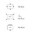
- FIGS. 1 and 2show the most pertinent types of handheld devices used for controlling electronic equipment.
- FIG. 1shows a mouse 101 that controls the position of a cursor 102 on the display 100 of a computer.
- the mouse 101typically has a track-ball mounted on its underside that is used to translate the position of the mouse on the horizontal surface 103 that it “rolls-on” into the position on the computer display 100 that the cursor 102 is displayed at.
- a typical mousewill transmit (e.g., wirelessly through a radio frequency (RF) transmitter or electronically through a cable) data that describes the rolling activity of the mouse's track ball to the computer.
- the computerin turn, translates this information into an appropriate screen position for the cursor 102 .
- the mouse 101also includes buttons that can trigger certain actions on the computer when the cursor 102 overlaps or points to a “button” or “menu” or other feature that is displayed on the computer screen 200 .
- FIG. 2relates to handheld devices used for controlling entertainment related electronic equipment.
- the typical systemincludes a television that is coupled to an external “box” 203 having circuitry designed to provide a certain type of “signal” to the television.
- Examples of such circuitryinclude cable TV receiver circuitry, satellite TV receiver circuitry, Video Cassette Recorder (VCR) circuitry, Digital Video Disk (DVD) player circuitry, gaming device circuitry, a computer's circuitry, music player circuitry (e.g., CD player circuitry, stereo receiver circuitry, etc.).
- VCRVideo Cassette Recorder
- DVDDigital Video Disk
- gaming device circuitrye.g., a computer's circuitry
- music player circuitrye.g., CD player circuitry, stereo receiver circuitry, etc.
- a remote control 201is often used to make user selections on a television display 200 .
- the opportunity to make selectionsis typically presented as some kind of software generated user interface that is superimposed over (or integrated with) a television signal.
- the user interfaceoften includes bordered regions and/or icons (e.g., regions/icons 204 , 205 ). Typically one of these regions/icons 204 , 205 is “highlighted” if the user is deemed to have implicated the particular region/icon.
- the userpresses one of a plurality of arrow buttons 202 that “point” in a direction where a next region/icon to be highlighted/implicated is located on the television display 200 .
- the remote control 201also typically includes a “select” button that, when pressed by the user, triggers some action (typically via transmission of infrared (IR) codes) by the television's circuitry or external box circuitry consistent with what the highlighted region/icon represents.
- IRinfrared
- FIG. 3shows that digital cameras have also been integrated into handheld devices. Besides standard “digital handheld cameras”, digital cameras have also been integrated in equipment having a traditional or primary purpose different than taking pictures. Cell phones, for instance, are now available having an integrated digital camera.
- FIG. 3shows a cell phone 301 in the process of taking a digital picture 302 .
- An item of electronic equipmentincludes a machine and executable program code.
- the executable program codeis stored on a non volatile memory.
- the executable program codeis to be executed by the machine.
- the executable program codeis to perform a method.
- the methodis in relation to a location on a display, or proximate to the display, that is pointed to by a handheld device.
- the methodincludes executing at least one of the following methods:
- FIG. 1shows a computer mouse (prior art)
- FIG. 2shows a remote control (prior art).
- FIG. 3shows a cell phone with an integrated digital camera (prior art).
- FIGS. 4 a through 4 cshow different depictions of absolute pointing
- FIG. 5 ashow an embodiment of a handheld device having an integrated camera for purposes of effecting absolute pointing of the handheld device relative to an electronic equipment display;
- FIG. 5 b through 5 eshow various layouts of marker(s) used for calculating an absolute pointing position
- FIGS. 6 a through 6 dshow different images captured by the handheld device's camera in relation to the manner in which a handheld device faces an electronic equipment display;
- FIGS. 7 a through 7 cshow different processes that can be executed to effect absolute pointing with a handheld device such as the handheld device of FIG. 5 a;
- FIGS. 8 a through 8 dshows three dimensional coordinate systems used for determining a handheld device's absolute pointing position on a display
- FIG. 9shows a process for determining a handheld device's absolute pointing position on a display
- FIGS. 10 a and 10 bshows a “virtual dial” function capable of being implemented if a handheld device's absolute pointing vector and roll position is known;
- FIG. 11shows an embodiment of a design for a handheld device capable of effecting absolute pointing control relative to an electronic equipment display
- FIG. 12shows an exemplary optical transfer function that can be implemented with the design presented in FIG. 11 ;
- FIGS. 13 a and 13 bshow different marker sizes that can be formed and directed to a handheld device's sensor
- FIG. 14shows a method for determining marker positions observed through a handheld device's sensor
- FIG. 15shows an exemplary collection of marker images observed through a handheld device's sensor
- FIG. 16shows sensor field of view for two different pointing directions
- FIG. 17shows a display and corresponding sensor image of the display for a one marker system
- FIG. 18shows calibration and “actual use” hand held device pointing situations
- FIG. 19shows markers radiating in two different directions
- FIG. 20shows marker images on a sensor for rolling hand held device
- FIGS. 21 a and 21 bshow a three marker system
- FIG. 22shows a four marker system
- FIGS. 23 a through 23 eshow different architectures that contain a processor.
- Absolute pointing from a handheld devicemay involve: 1) determining a location on, or proximate to, a display where a handheld device is being pointed; and, 2) rendering some kind of image (e.g., a cursor, icon, highlighted region, menu choice) at that location, and/or, triggering some kind of action from a user interface feature presented at that location.
- some kind of imagee.g., a cursor, icon, highlighted region, menu choice
- Absolute pointing from a handheld devicemay also, or by itself, involve: 1) determining a location proximate to a display where the handheld device is being pointed (e.g., the location of specific electronic equipment placed proximate to the display); and, 2) rendering some kind of image (e.g., a cursor, icon, highlighted region, menu choice) on the display, and/or, triggering some kind of action from that location (e.g., causing the specific electronic equipment to render an image or take some specific action as a consequence of its being pointed to).
- a location proximate to a display where the handheld device is being pointede.g., the location of specific electronic equipment placed proximate to the display
- rendering some kind of imagee.g., a cursor, icon, highlighted region, menu choice
- Absolute pointing from a handheld devicemay also, or by itself, involve: 1) determining that a specific appliance (e.g., a lamp) or other type of electrical equipment is being pointed to; and, 2) triggering some kind of action at that appliance or other type of electrical equipment.
- a specific appliancee.g., a lamp
- triggering some kind of action at that appliance or other type of electrical equipmente.g., a lamp
- the handheld devicemay point to a feature that is part of a user interface (e.g., an icon or menu choice) that is displayed on the display.
- the featureis understood to mean that some kind of action will be taken by electronic equipment controlled through the user interface (e.g., the selection of a television signal, the opening of a file, the startup of a software routine, etc.). If a user holding the handheld device takes some kind of action (e.g., presses a button on the handheld device or “jerks” his/her wrist), a signal is sent from the handheld device that is ultimately interpreted to mean that the action suggested by the feature is desired by the user.
- some kind of actione.g., presses a button on the handheld device or “jerks” his/her wrist
- FIGS. 4 a through 4 cdemonstrate examples of absolute pointing between a handheld device 401 and a display 400 ′, where, the handheld device 401 is located in a different position and points to a different display location (“X”) across each of FIGS. 4 a through 4 c .
- Each of FIGS. 4 a through 4 cshow a facing view (i), a top view (ii), and a side view (iii) for their respective handheld device 401 and display 400 ′ orientation.
- the facing views 4 a (i), 4 b (i), 4 c (i)show their respective handheld device 401 and display 400 ′ orientation from a perspective that is directly in front of and facing the display 400 ′.
- the top views 4 a (ii), 4 b (ii), 4 c (ii)show their respective handheld device 401 and display 400 ′ orientation from a perspective that is above the display 400 ′ looking directly down to the top of the display 400 ′ and the handheld device 401 .
- the side views 4 a (iii), 4 b (iii), 4 c (iii)show their respective handheld device 401 and display 400 ′ orientation from a perspective that is off the display's “left” hand side looking directly at the display's side and the handheld device's side 401 .
- the term “left”is taken from the perspective of viewer standing in front of and facing the display 400 ′.
- the +y′ directionis a direction that moves vertically relative to a viewer of the display 400 ′ surface
- the +x′ directionis a direction that moves horizontally to the right 400 ′ relative to a viewer of the display surface
- the +z′ directionis a direction that moves directly away from the front of the display 400 ′ surface.
- FIG. 4 ashows a first set of perspectives when the handheld device 401 is beneath the display's left hand side and points to a location near the display's upper right hand corner.
- FIG. 4 bshows a second set of perspectives when the handheld device 401 is beneath the display's right hand side and points to a location near the display's lower left hand corner.
- FIG. 4 cshows a third set of perspectives when the handheld device 401 is above the display's left hand side and points to a location near the display's lower right hand corner.
- a cursorwould be made to appear at each “X” location observed in FIGS. 4 a (i), 4 b (i) and 4 c (i).
- some kind of user interface or iconmay be presented at each “X” location observed in FIGS. 4 a (i), 4 b (i) and 4 c (i).
- FIG. 5 ashows a more detailed embodiment of a handheld device 501 , display 500 ′ and electronic equipment 503 capable of effecting absolute pointing as described just above with respect to FIGS. 4 a through 4 c .
- the handheld device 501includes a camera and wireless transmitter 505 .
- Information taken or processed from an image captured by the handheld device's camerais transmitted by the handheld device's wireless transmitter to a wireless receiver 508 .
- the communication between the handheld device and the electronic equipment 503may be achieved using a wired connection, such as Universal Serial Bus (USB) or RS-232 serial cabling.
- USBUniversal Serial Bus
- Electronic circuitry(such as a processor 507 , or a controller, or circuitry that does not execute program code) that is responsible for controlling the presentation of a cursor on display 500 and/or presenting a user interface on the display 500 ′, receives the information sent by the handheld device 501 .
- the electronic circuitrymay be integrated in various types of electronic equipment.
- electronic equipment 503may be any of: a) a television; b) a satellite TV receiver; c) a cable TV receiver; d) a VCR; e) a DVD player; f) a computer; g) a CD player; h) a music receiver and/or player; i) a video game box or some other type of equipment containing gaming circuitry; j) an IPTV receiver and/or television; k) a “receiver” that receives signals from one or more of items of electronic equipment such as those listed in a) through j) above; 1) home and/or office automation equipment (e.g., equipment including circuitry for turning household switches “on” and “off”).
- home and/or office automation equipmente.g., equipment including circuitry for turning household switches “on” and “off”.
- the electronic circuitryin response to the receipt of this information, causes a cursor (or other image) to be presented at the display location where the handheld device 501 is pointing and/or causes a user interface feature that is at the display location where the handheld device 501 is pointing to be highlighted in some fashion.
- a cursoror other image
- fixed markers 504 ′_ 1 and 504 ′_ 2which are detectable by a sensor, are positioned proximate to the display 500 ′.
- a cursorBy capturing the positions of these fixed markers 504 ′_ 1 through 504 ′_ 2 with the handheld device's camera, and, through the automated execution of mathematical relationships (at the handheld device, with the aforementioned electronic circuitry, a combination of both, etc.) that relate the observed marker positions to the pointed to location on the display surface, a cursor can be made to appear at the pointed to display location, and/or, some kind of action can be triggered from a user interface feature presented at the pointed to display location.
- the fixed markers in FIG. 5 aare one possible two-marker arrangement. Other arrangements that comprise one, two, three, four, or more markers placed in other locations relative to both each other as well as the display 500 ′ are possible.
- various arrangements of various numbers of markersmay be used to enable absolute pointing.
- the positioning of the marker(s)will “move” from the perspective of the handheld device's sensor along the same axis.
- the pixel location(s) of the marker(s) along the x axis of the handheld device's sensorwill change.
- the specific placement of the marker(s)can be varied from embodiment to embodiment.
- increasing the number of markersenables the ability to more precisely calculate the handheld device's pointing position. Nevertheless, as described in more detail further below in Section 4.0, sufficient accuracy for at least some applications is conceivable where only a single marker is used.
- FIGS. 5 b through 5 eexplore some possible marker layout arrangements for single marker ( FIG. 5 b ), two marker ( FIG. 5 c ), three marker ( FIG. 5 d ) and four marker ( FIG. 5 e ) embodiments.
- the distance between the marker and displaymay vary (of course, the distance should not be such that the marker can not be seen by the handheld device).
- FIG. 5 bshows an embodiment where a single marker 514 is placed along the side of the display. In alternate approaches the marker may be placed in or about the corner of the display.
- FIG. 5 c (i)shows a two marker embodiment where both markers 515 _ 1 , 516 _ 1 are positioned along the same side of the display.
- FIG. 5 c (ii)shows another embodiment where each of the pair of markers 5152 , 516 _ 2 are positioned along different display sides.
- one or both markers of a two marker embodimentmay be positioned in or about one or more corners of the display (e.g., by placing the pair of markers around the same corner, or putting a first marker at a first display corner and the second marker at another display corner).
- the pair of markersmay be placed at the same or in different z′ positions.
- FIGS. 5 d (i) through 5 d (iv)show various three marker embodiments.
- FIG. 5 d (i)shows each one of three markers positioned along a different display side.
- FIG. 5 d (ii)shows each one of three markers positioned along a same display side.
- FIG. 5 d (iii)shows three markers along a same display side where two of the markers have a same y′ axis location.
- FIG. 5 d (iv)shows three markers along a same display side where one marker has a different z′ location than the other two markers.
- Various other arrangementsare also possible. Generally, as long as the three markers can be seen by the handheld device and they each possess a unique x′,y′,z′ location a workable system can be implemented.
- FIG. 5 e (i) through 5 e (iii)show various four marker embodiments.
- each one of the markersis positioned along a different side of the display.
- each of the markersis positioned in a different corner of the display.
- more than one markeris positioned along a same side of the display.
- FIGS. 6 a through 6 dshow images of markers for a two marker system, as observed through the handheld device's camera, for different handheld device positions and pointing orientations relative to the display surface (similar to FIGS. 4 a through 4 c ).
- Each of FIGS. 6 a through 6 dinclude four sub-figures (i) through (iv).
- Each of FIGS. 6 a (i), 6 b (i), 6 c (i) and 6 d (i)include exemplary images 604 _ 1 , 604 _ 2 of the display markers 604 ′_ 1 and 604 ′_ 2 as observed on a pixilated sensor 610 that corresponds to the “image capture” portion of the handheld device's camera.
- FIGS. 6 b (ii), 6 c (ii) and 6 d (ii)show a front view of the respective handheld device position and pointing direction
- FIGS. 6 b (iii), 6 c (iii) and 6 d (iii)show a top view of the respective handheld device position and pointing direction
- FIGS. 6 b (iv), 6 c (iv) and 6 d (iv)show a side view of the respective handheld device position and pointing direction.
- the (x′,y′,z′) coordinate system described above with respective FIGS. 4 a through 4 cis preserved for the (ii), (iii) and (iv) sub-figures of FIGS. 6 a through 6 d.
- a new co-ordinate axis (x,y)is introduced to represent the pixilated sensor's specific pixel locations.
- the +y directioncorresponds to vertical movement up the surface of the sensor
- the +x directioncorresponds to horizontal movement to the right along the surface of the sensor.
- Pixilated sensorsmay be made from various technologies such as CMOS, CCD, or photodiode arrays.
- FIGS. 6 a (ii) through 6 a (iv)indicate that the handheld device 601 is directly facing the center of the display 600 ′.
- the location 602 ′ on the display 600 ′ that is pointed to by the handheld device 601corresponds to the center of the display 600 ′.
- the markers 604 ′_ 1 and 604 ′_ 2will appear as images 604 _ 1 and 604 _ 2 on the handheld device's sensor 610 .
- an initial calibration procedureis needed in order to determine values for variables that appear within mathematical relationship(s) that convert a detected marker position on the sensor 610 into the position on the display 600 ′ where the handheld device is pointing.
- the calibrationmay be performed and any specific procedure may depend on the specific embodiment of the system being used.
- the userpoints at one or more defined locations (generally, on or near the screen) and the handheld device records the marker image 604 _ 1 , 604 _ 2 positions on the sensor array 610 (a more detailed description of specific calibration procedures is given in section 4.0 below).
- the calibration proceduremay involve pointing sequentially at visible markers (typically two) displayed temporarily on the screen (e.g., in opposite corners).
- changes in observed marker image 604 _ 1 , 604 _ 2 position on the sensor 610 surface in response to changes in the handheld device's location and pointing directioncan be defined in reference to their original calibration positions; which, in turn, can be related to a position on the display 600 ′ where the handheld device 601 is pointing.
- the observed changes in the marker image positions of FIG. 6 b (i)can be mathematically related to the handheld device's correct pointing location on the display 600 ′; which, in turn, can be used to generate a cursor at the pointing location or trigger an action from a user interface feature that appears at the pointing location.
- a thorough discussion of such mathematical relationshipsis presented in more detail further below in section 4.0 entitled “Mathematical Relationships For Absolute Handheld Device Pointing”.
- section 4.0Mathematical relationships suitable for implementing one, two, three and four marker systems are presented in section 4.0. Although the relationships provided in section 4.0 primarily present relationships for determining a handheld device's absolute pointing direction, location, and orientation on or proximate to a display location through analysis of detected marker image position, it is also theoretically possible to enhance the accuracy of these systems through analysis of marker image size and shape.
- the observed changes in the marker image positions of FIG. 6 c (i)can be mathematically related to the handheld device's correct pointing location on the display 600 ′; which, in turn, can be used to generate a cursor at the pointing location or trigger an action from a user interface feature that appears at the pointing location.
- FIG. 6 d (i)shows observed sensor images when the handheld device 601 moves directly to its left from its position in FIG. 6 c , but, adjusts its pointing direction so as to keep pointing to the same display location 602 ′ that is pointed to in FIG. 6 c .
- the handheld devicedoes not make any changes along the y′ axis, the y coordinate values of the marker images 604 _ 1 and 604 _ 2 remain unchanged in FIG. 6 d (i) when compared against their values in FIG. 6 c (i).
- the face of the handheld devicehas made substantial changes along both the x′ axis and the z′ axis, the x coordinate values for the marker images change substantially from their values in FIG. 6 c (i).
- the observed changes in the marker image positions of FIG. 6 d (i)can be mathematically related to the handheld device's correct pointing location on the display 600 ′; which, in turn, can be used to generate a cursor at the pointing location or trigger an action from a user interface feature that appears at the pointing location.
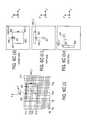
- FIGS. 7 a through 7 cshows methodologies that can be executed by absolute pointing handheld device systems having different system designs. Most notably, the difference between the various designs involves the degree of processing that is performed by the handheld device. Referring to FIG. 5 a as well as FIG. 7 a , FIG. 7 a depicts a method in which the handheld device 501 not only captures the marker image data, but also performs all of the mathematical relationship calculations needed to translate the observed marker image positions into a specific pointed to location on the display 500 .
- the handheld device 501transmits 714 the coordinates of the pointed to location on the display to the wireless receiver 508 .
- the overall processincludes the handheld device 501 : 1) capturing 711 marker image data with its camera; 2) identifying 712 the positions of the respective marker images on the camera's pixilated sensor; 3) determining 713 the handheld device's pointed to location on the display through calculations with mathematical relationships; and 4) sending 714 the pointed to location to a wireless receiver 508 .
- Electronic circuitry responsible for controlling displayed content on the display 500may then cause some effect to appear at the pointed to location 715 (e.g., a cursor, highlighting a menu feature, etc.).
- FIG. 7 bdepicts a method in which the handheld device 501 does not determine the handheld device's pointed to location on the display through calculations with mathematical relationships, but, besides capturing 721 marker image data with its camera also identifies 722 the positions of the respective marker images on the camera's pixilated sensor. As such, the handheld device 501 transmits 723 the marker positions to the wireless receiver 508 .
- Electronic circuitry responsible for controlling displayed content on the display 500receives the marker positions and determines 724 the handheld device's pointed to location on the display through calculations with mathematical relationships; and, may then cause some effect to appear at the pointed to location 725 (e.g., a cursor, highlighting a menu feature, etc.).
- FIG. 7 cdepicts a method in which the handheld device 501 does not determine the handheld device's pointed to location on the display nor identify the positions of the respective marker images on the camera's pixilated sensor. Instead, the handheld device 501 simply captures 731 the marker images with its camera and transmits 732 information describing these images to the wireless receiver 508 .
- Electronic circuitry responsible for controlling displayed content on the display 500receives the marker image data and: 1) identifies 733 the positions of the respective marker images on the camera's pixilated sensor; 2) determines 734 the handheld device's pointed to location on the display through calculations with mathematical relationships; and, 4) may then cause some effect to appear at the pointed to location 735 (e.g., a cursor, highlighting a menu feature, etc.).
- each of FIGS. 7 a through 7 cnote that the image data is repeatedly captured 711 , 721 , 731 over time so that new pointed to locations on the display can be determined with rapid regularity (e.g., so that a cursor's movement can be at least quasi-fluidly tracked on the display 500 ). Moreover, note that each of FIGS. 7 a through 7 c demonstrate a process in which an effect is made to appear on the display at the pointed-to location. Alternatively or in combination, additional information in the form of a “button press” or “roll action” of the handheld device may be sent from the handheld device in order to trigger electronic equipment to take some kind of action.
- circuitry responsible for determining displayed contentmay interpret the collection of information sent from the handheld device to mean that the user has selected the icon or menu item.
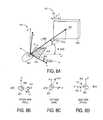
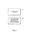
- FIGS. 8 a through 8 d and 9provide some higher level details that can be applied, at least in certain embodiments, to useable mathematical relationships that translate observed marker image positions to a specific pointed to location 802 ′ on or proximate to the surface of the display 800 ′.
- FIGS. 8 a through 8 dillustrate various three-dimensional concepts that may be defined and applied in a certain set of applicable mathematical relationships.
- determination of the pointed to location 802 on the display 800 ′involves: 1) determining 901 a scaling factor (M); and, 2) executing 902 mathematical relationship(s) that use the scaling factor M to translate an sensor axis location where a marker is observed to a corresponding axis location on the display where the handheld device is pointing.
- a first scaling factor M Xis calculated for one device/display coordinate axis pair (x, x′) and a second scaling factor M Y is calculated for a second device/display coordinate axis (y, y′).
- the process observed in FIG. 9is essentially executed twice, once for the x,x′ axis pair and the other for the y,y′ axis pair.
- the scaling factor M Xis essentially a ratio between the observed change in position of a marker on the sensor along the x axis, relative to a specific sensor position along the x axis, and the change in position of the pointed to location along the x′ axis on the display, relative to a specific position on the display along the x′ axis; where, the specific sensor and display positions are determined during calibration. As described in more detail below in section 4.0, the accuracy of the scaling factor can be made to improve if additional details concerning the handheld device are gleaned from the observed marker images.
- the accuracy of the scaling factorcan be enhanced if the position of the handheld device relative to the display (e.g., the distance L 820 between the center of the display 802 and the front of the handheld device) and/or the orientation of the handheld device relative to the display (e.g., the viewing angle 0 of the handheld device 901 ) is determined.
- the separation between all marker image positionsscales inversely with distance from the display and the relative separations of different pairs of marker image positions depends on the handheld device angle with respect to the display surface.
- FIGS. 8 a and 8 balso indicate that another characteristic of the handheld device's orientation, referred to as the handheld device's “roll” ⁇ , can be tracked from the marker image positions.
- the handheld device's rollcorresponds to the handheld device's rotation about the axis of its pointing vector (i.e., the vector protruding from the front of the handheld device whose intercept with the display corresponds to the pointed-to location on the display).
- the handheld device's roll ⁇the collective rotation of the marker image positions is detected.
- the pointing vectoris assumed originate from the center of the handheld device's sensor array.
- FIGS. 8 a and 8 dshow the pitch y of the handheld device. The effective pitch or change in effective pitch of the handheld device can also be determined so as to more accurately define the pointed to position on the display.
- the handheld device's rollcan be used to trigger some kind of action taken by electronic equipment. For instance, a “twist of the wrist” of the user can be interpreted as a “button press” (e.g., the user points the handheld device to an icon or user interface menu item and then twists his/her wrist to “select” that icon or menu item).
- FIGS. 10 a and 10 bdemonstrate another useful application of tracking a handheld device's roll action.
- a depiction of a dial 1010is displayed on the display.
- the dialis illustrated as being set to a value of LOW 1011 .
- the dialmay be displayed so as to rotate in conjunction with the user's wrist rotation(s).
- the userhas pointed the handheld device to the dial and twisted his/her wrist clockwise 1002 .
- the displayed virtual dial 1010rotated clockwise until the user's wrist rotation was deemed “stopped”; which, according to FIG. 10 b , was at a setting of MID 1011 .
- the useris expected to press a button on the hand held device during the rotation of the handheld device in order to activate the rotation of the dial 1010 (i.e., the user must press a button in combination with the wrist rotation).
- the handheld devicesends: 1) the pointed to location on the display (or information from which the pointed to location on the display can be determined); 2) the roll position(s) of the handheld device (or information from which the handheld device's roll action can be determined); 3) information that signifies the user is pressing a button.
- the markersthemselves act as the source of the light that is detected by the handheld device's sensor (e.g., the markers are implemented as LEDs).
- the handheld deviceacts as the source of light that is detected by the handheld device's sensor.
- the handheld devicecontains an infrared (IR) “flashlight”, which shines IR light into the region of the display and each marker is implemented as a “passive” reflector. Additional image processing may be used to enhance the signal-to-noise ratio. For example, characteristics of the emitted light that are detectable to the handheld device could be subtracted from the reflected images to essentially improve the signal to noise ratio of the detected marker images.
- IRinfrared
- the flashlightis “strobed” such that a representation of the emitted light to be subtracted from each detected marker image is taken just prior to the detecting of a marker image.
- an IR filtermay be placed over the camera to aid in the rejection of unwanted light.
- reflective markersinclude the application of a single handheld device to multiple appliances through the use of, for instance, home and/or office automation circuitry.
- the reflective reference markersare located on or near the appliance to be controlled, and, for each device, the reflective markers are arranged in a predetermined spatial pattern.
- the handheld devicecan then recognize a particular appliance by recognizing its specific pattern.
- one or more of the appliancesmay not even have a display.
- the appliances themselves and/or their remote usemay be simplistic (e.g., having only a few states such as “on” and “off”) such that the simple act of pointing to the appliance and making one or a few button presses on the handheld device is sufficient to enable use of the device.
- Example of such appliancesinclude lamps, radios and televisions.
- Various formatscan be used for the spatial marker patterns that identify a specific device/appliance. Examples include ones similar to those used in bar-codes (i e., universal product codes), and simple on/off binary codes.
- the number of required markers per appliancewill depend on the number of different appliances that need to be identified and/or the pattern format used. For most household applications it is likely that this number will be small (less than five).
- the handheld deviceWhen the handheld device is pointed at an appliance (e.g., a lamp) and the appropriate button(s) on the handheld device is pressed (and/or an appropriate gesture is made with the device), the handheld device is programmed to send the appropriate command by wireless transmission (e.g., RF or IR) to the appliance, either directly or through a central command unit (e.g., electronic equipment 503 such as an X10) that actually sends the command to the pointed to appliance directly.
- an appliancee.g., a lamp
- a central command unite.g., electronic equipment 503 such as an X10
- the commandis sent in a packet that includes the identity of the appliance being pointed to (i.e., the handheld device is programmed with the pattern recognition capability to identify each specific appliance).
- the handheld devicesends the image pattern and handheld device action (e.g., button press, rolling action, etc.) or command to another device (e.g., the aforementioned central command unit).
- the other devicethen: 1) recognizes the pointed to appliance; and 2) sends/forwards a command to the pointed to appliance.
- a variety of commandsmay be communicated to an appliance including simple power on/off and increase/decrease of different appliance properties (e.g., light intensity, oven temperature, sound volume, etc.).
- the applianceIn cases where the handheld device directly commands an appliance, or in cases where an intermediate unit (e.g., the aforementioned command unit) wirelessly commands an appliance, the appliance will need to be configured with some sort of command detection and functional effectuation circuitry that may be fairly regarded as home and/or office automation circuitry (e.g., a integrated circuit having a wireless receiver coupled to a processor/controller (with executable code) and/or logic state machine circuitry (no executable code) that is coupled to a switch or other functional effectuation circuitry (such as a “selection” or “setting” circuitry (e.g., channel setting/selection, temperature setting/selection, volume setting/selection, etc.)).
- a “selection” or “setting” circuitrye.g., channel setting/selection, temperature setting/selection, volume setting/selection, etc.
- FIG. 11 and 12relate to a handheld device's hardware design.
- a handheld devicemay include an aperture 1101 (positioned on the front face of the handheld device), an optical channel 1102 that include various optical component (e.g., lenses, diffusers, filters, etc.), and a pixilated sensor 1103 .
- the aperture 1101 , optical channel 1102 and sensor 1103form a digital camera whose output 1109 is coupled to a processor or controller 1104 (alternatively, the digital camera's output values can be written into a memory 1105 from where they are read and provided to the processor or controller 1104 ).
- Program code 1106is executed on the processor/controller 1104 so that various functions can be performed (e.g., marker image position detection, mathematical calculations for relating detected marker image positions to a specific pointed to display location, mathematical calculations for relating detected marker image positions to the handheld device's roll position, wired or wireless communication reception and transmission protocols, etc.).
- a non-volatile memory devicefor storing the handheld device's program code, nor, one or more buttons that are coupled to the processor/controller 1104 .
- memory 1105is made of Dynamic Random Access Memory (DRAM) cells because of its low cost and low power consumption.
- DRAMDynamic Random Access Memory
- a controlleris understood to be a processor having a specially targeted instruction set.
- a processoris understood to be logic circuitry designed to execute program code 1106 instructions. Different forms of processors and controllers exist such as micro-processors, micro-controllers, embedded processors and embedded controllers.
- the processor or controlleris also coupled to wireless transceiver circuitry 1107 ; which, in turn, is coupled to an antenna 1108 that sends/receives wireless signals.
- processor/controller 1104could be replaced with dedicated logic circuitry designed to perform the applicable mathematical calculations and/or marker image position detection functions.
- data from the pixilated sensor 1103is processed by the processor/controller 1104 to detect the marker image positions on the pixilated sensor 1103 .
- the processor/controller 1104then executes mathematical calculations to relate the marker image positions to a specific pointed-to display location.
- the processor/controller 1104then prepares data that identifies the pointed-to location for wireless transmission and causes it to be forwarded to the wireless transceiver circuitry 1107 which in turn causes it to be sent from the wireless device.
- Wireless transceiver circuitryincludes both transmitting and receiving circuitry.
- circuitry 1107is wireless transmitter circuitry (i.e., the handheld device is not designed to receive and process wireless signals other than the electromagnetic radiation that enters the camera's aperture).
- wireless solutionsexist such as the wireless Universal Serial Bus (USB), Z-Wave, IR, IEEE 802.15.1 (BLUETOOTH), IEEE 802.15.4 (ZigBee), or IEEE 802.11 (WiFi) standards, as well as wired solutions such as the USB or RS-232 serial standards.
- the handheld devicesends information to the electronic equipment through wiring rather than wirelessly.
- the wireless transceiver 1107 and antenna 1108are replaced with driver circuitry 1107 and wiring that is coupled to the applicable electrical equipment.
- data from the pixilated sensor 1103is processed by the processor/controller 1104 to detect the marker image positions on the pixilated sensor 1103 .
- the processor/controller 1104then prepares data that identifies the marker image positions for wireless transmission and causes it to be forwarded to the wireless transceiver circuitry 1107 which in turn causes it to be sent from the wireless device.
- data from the pixilated sensor 1103is prepared for wireless transmission by the processor/controller 1104 and causes it to be forwarded to the wireless transceiver circuitry 1107 which in turn causes it to be sent from the wireless device.
- the processor/controller 1104is replaced with circuitry that merely forwards pixilated sensor data to the wireless transceiver circuitry 1107 .
- the wireless transceiver circuitry 1107could conceivably be replaced with driver circuitry for driving electrical signals from the handheld device over cabling toward the display.
- FIG. 12shows an exemplary optical channel design for the handheld device's camera.
- a “bandpass filter”is essentially created with the optical transfer function of the pixilated sensor 1103 and the transfer function of an optical filter that is built into the handheld device's optical channel 1102 .
- the pixilated sensor 1103is a silicon-based CMOS device.
- Other sensor typessuch as CCD and photodiode arrays may also be used.
- CMOS deviceshave an optical transfer function 1203 that essentially corresponds to a low pass filter that rolls off on the high end of its passband above a peak response near 940 nm.
- the optical channel 1102is made to include an Infrared (IR) high pass filter 1202 that rolls off on the low end of its passband below 940 nm.
- IR-pass filterssuch as a Kodak Wratten 87C, Hoya IR-85, or their equivalents are appropriate for this purpose.
- the combination of these two filters 1202 , 1203results in a narrow passband 1210 around 940 nm.
- the markers 504 _ 1 through 504 _ 4themselves are made to be IR transmitters (e.g., Light Emitting Diodes (LEDs))
- the pixilated sensor 1103will present a strong detected “signal” at its output 1109 that corresponds mostly to the electromagnetic radiation received from the markers 504 _ 1 through 504 _ 4 with little background from other electromagnetic radiation that is received through the handheld device's aperture 1101 .
- the handheld device 501may be designed to include its own IR transmitter and the markers 504 _ 1 through 504 _ 4 may be implemented as mere mirrors (or, further, IR reflecting mirrors).
- the transfer function of the optical channel 1102 itselfmay be a specific passband (e.g., by including both a high pass filter and a low pass filter).
- the transfer function of the optical channel 1102may be made to correspond to a low pass filter.
- the designed-for passband of the camera as a wholemay be just a high pass filter or a low pass filter.
- little or no optical filteringmay be performed in hardware, rather, filtering (if any) is performed in software by the processor/controller 1104 ; or, with dedicated logic circuitry.
- the wavelength of the electromagnetic radiation that is used to form the marker imagesis a matter of design choice. Besides a spectrum that resides within the IR spectrum (approximately 800-950 nm), other possible wavelength ranges for the marker images may be used.
- CMOS and CCDcomplementary metal-oxide-semiconductor
- the optical channel 1102may be made to include a diffuser or an “out-of-focus” optical path to deliberately blur a marker image so that it is easier to detect.
- the larger marker sizecan permit more accurate determination of the true center position of the marker. This may be achieved using interpolation algorithms that result in sub-pixel resolution.
- FIGS. 13 a,b , 14 and 15relate to marker image position detection processing methods.
- marker image position detectionis performed by the handheld device.
- marker image position detectionis performed by circuitry associated with electronic equipment that is responsible for controlling the displayed content on the display (or at least circuitry that is coupled to such circuitry).
- FIG. 13 ashows a depiction of a pixilated sensor illuminated by a marker image's radiation.
- the passband of the handheld device's cameracorresponds to a bandpass filter (e.g., as described with respect to FIG. 12 ) such that, ideally, only electromagnetic radiation from a marker is responded to by the pixilated sensor, then, the amount of marker radiation that a pixel receives will determine that pixel's output value.
- each pixelhas an 8 bit output allowing for 256 different intensity values.
- FIG. 13 ahas depicted as “dark” those pixel regions that are illuminated with radiation from a marker. Notably a darkened circle is observed.
- Pixels within the circlewould therefore ideally have values toward 256, pixels at the periphery of the circle would have values around 128, and, pixels outside the circle would have values around 0.
- the collection of these values correlated to the two-dimensional (x,y) coordinates of their corresponding pixelscorresponds to the marker's image (or, the pixilated sensor's output signal for this marker image).
- FIG. 13 bshows a representation 1302 of a marker image that is larger than the marker image of FIG. 13 a .
- FIG. 13 arepresents a marker image when the optical processing in the optical channel 1102 is designed to focus a marker image to a small image.
- FIG. 13 bshows the same marker image if the optical channel 1102 includes a diffuser or is intentionally designed with the sensor 1103 positioned before or after the optical channel's output focal point so that the marker image is deliberately blurred. By deliberately blurring the marker image, the marker image is easier to detect by marker position detection algorithms.
- marker image size and signal strengththat depends on several system factors such as the marker image signal strength, the sensor sensitivity, the noise and background signals on the sensor, the marker spacing, and the maximum distance from the markers to the user (the marker images should not be broadened further once they start to impinge on each other on the sensor), etc.
- FIGS. 14 and 15relate to a marker position detection technique.
- FIG. 14shows a process for detecting the position of multiple marker images that are presented by the handheld device's sensor.
- FIG. 15provides an exemplary depiction of a sensor's output signal.
- a marker imagein a simple case a “marker” such as marker 1505 ′_ 1 of FIG. 15
- a markercan be recognized, for instance by identifying a region of the sensor's pixel array having a sufficient number of neighboring pixels that are providing a “high” output value (above a predetermined threshold).
- pixel data within a region 1402 , 1520 around the found marker 1504 ′_ 1is further processed to identify the “location” of the marker.
- the marker image 1302 of FIG. 13 bcan be viewed as an exemplary illustration of the data that is associated with region 1504 ′_ 1 . Recalling that each pixel location has an associated intensity value that increases as the amount of radiation from a marker that illuminates the pixel location increases, the marker image 1302 of FIG. 13 b can be viewed as an array of intensity values.
- the intensity valuesare summed “horizontally” 1403 ′_ 1 along the x axis to produce, for each row of data in the extracted data region 1504 ′_ 1 , a sum total intensity value for that row. Owing to the shape of the marker image, the distribution of these sum total intensity values across the vertical expanse of the extracted data region 1504 ′_ 1 should approximate that of a “bell-curve” 1305 (e.g., Gaussian or Gaussian-like distribution). Similarly, the intensity values are summed “vertically” 1403 ′_ 2 along the y axis to produce, for each column of data in the extracted data region 1504 ′_ 1 , a sum total intensity value for that column.
- a “bell-curve” 1305e.g., Gaussian or Gaussian-like distribution
- a curve fitting function 1404 _ 1 , 1404 _ 2is then applied to each of these distributions 1303 , 1305 to define a fitted, continuous curve 1304 , 1306 for each of them.
- the maximum value of the horizontal fitted curve 1304is then taken as the x coordinate value 1307 (x o ) of the position of the marker image 1405 _ 1
- the maximum value of the vertical fitted curve 1306is then taken as the y coordinate value 1308 (y o ) of the position of the marker image 1405 _ 2 .
- the processthen repeats 1407 for the next marker until all markers have been found and their positions determined.
- other methods for center determinationmay be used and may be beneficial, especially in cases where the beam profiles are not smooth or symmetric functions.
- One such methodessentially determines the width (e.g., full-width half-maximum—FWHM) of the fitted curves and takes the marker center to be the center position between the FWHM points. In this case, the center may not be the same as the peak location. Other variations on this approach may also be used. Using these marker center determination algorithms sub-pixel resolution appears to be possible. The achievable resolution is limited by the noise in the signal and the number of bits of sampling in the digital sensor. For example, a noiseless signal sampled with 8-bit digitization would permit less than 0.005 pixel spatial resolution. Signal averaging may increase this resolution even further. In practice, the existence of system noise and background signals results in reduced resolutions that typically range between 0.01 and 0.1 pixels.
- FWHMfull-width half-maximum
- a primary taskis to relate the pointing direction of a sensor located in the hand-held device to the desired cursor location on the display.
- Thisis generally a two-dimensional problem involving horizontal and vertical coordinates for both the display (x′,y′) and the sensor (x,y). Since the axes are orthogonal, the relevant equations are separable and the formulas can be derived for each axis independently. Accordingly, calculations for the horizontal axes (x′ and x) are first presented. These are then extended to the vertical axes (y′ and y).
- FIG. 16shows coordinate systems and sign convention. Two different pointing directions in the horizontal dimension are illustrated, from a “top view” perspective, to show how the variables are related. A similar picture may apply for the vertical dimension.
- x 0is the coordinate origin of the sensor 1603 or coordinate that corresponds to the desired pointing direction (in a preferred embodiment x 0 is near the center pixel on the sensor 1603 , or, better said, the sensor's field of view 1604 is centered at the cursor x CUR ′);
- x REFis the position on the sensor 1603 of the reference marker image (which moves as the sensor 1603 moves);
- x REF ′is the actual position of the reference marker with respect to the display 1600 ′;
- x CUR ′is the desired cursor position on the display 1600 ′ (which also
- Mdepends on several systems factors (e.g., sensor position with respect to the display, sensor field of view, display size, and orientation of the sensor with respect to the display), and, in general, x,x′ and y,y′ coordinates can have different values (magnitude and sign) for M (M x and M y ).
- Equation (1)indicates that the reference marker to display cursor distances 1605 _ 1 , 1605 _ 2 and the reference marker image to sensor origin distances 1606 _ 1 , 1606 _ 2 , in their respective local coordinate systems, are linearly related (i.e., proportional), and the proportionality constant, or scale factor, is M.
- the x and y positionswill correspond to the pixel number on the sensor 1603 and the x′ and y′ positions will correspond to the pixel number on the display 1600 ′. Also note that the pixel numbers are relative to the total number of pixels in the respective coordinate systems, and thus x (y) and x′ (y′) should be normalized accordingly.
- the factors in (1) that are determined during calibrationare M x , x 0 , and x REF ′ (where, x REF is the measured reference marker pixel number on the sensor 1603 and x CUR ′ is the output of the algorithm—the pixel number of the display cursor).
- x 0could be any particular pixel number corresponding to the origin on the sensor 1603 , however, the approximate center is the most natural to use.
- a sensor with an array size of 640 ⁇ 480would have x 0 ⁇ 320 and y 0 ⁇ 240.
- these valuesdo not need to be explicitly determined prior to calibration. In effect, x 0 and y 0 are automatically determined during calibration, as will be shown below.
- M x and x REF ′are the two factors that are explicitly determined during calibration.
- One method for determining x REF ′could be to physically measure its x′ position and corresponding relative pixel number on the display 1600 ′. Note that it is not necessary for the reference marker to be physically located within the display 1600 ′ itself.
- a simpler and more accurate method to determine both x REF ′ and M x simultaneouslyis to use two visible calibration reference points displayed at known positions on the display 1600 ′.
- the calibration reference pointswill have different x and y coordinates, e.g., located at opposite corners of the screen.
- x CALA ′ and x CALB ′represent the known calibration reference point positions
- x REFA and x REFBare the corresponding recorded sensor image positions of the reference marker.
- M x- ⁇ ⁇ ⁇ x CAL ′ ⁇ ⁇ ⁇ x REF ( 4 )
- ⁇ x CAL ′is the separation (in pixels) of the calibration reference points on the display (x CALA ′ ⁇ x CALB ′)
- ⁇ x REFis the measured separation (in pixels) of the corresponding marker image positions on the sensor (x REFA ⁇ x REFB ).
- x CUR ′M x ⁇ [ 1 2 ⁇ ( x REFA + x REFB ) - x REF ] + 1 2 ⁇ ( x CALA ′ + x CALB ′ ) ( 7 ) with M x determined from equation (4).
- the first term on the right hand side of equation (7)represents the average pixel position of the marker images on the sensor (1/2(X REFA +X REFB )), during calibration, relative to the actual pixel position of the reference marker image (X REF ) for a given pointing direction, all scaled by M x . It essentially determines the amount that the cursor on the display 1600 ′ should move as the reference image moves on the sensor 1603 .
- the second term on the right hand sideis the average pixel position of the calibration reference points on the screen and it represents any offsets that are applied to the cursor position in order to effect line-of-sight pointing.
- FIG. 17shows an example of the various (x and y) coordinates in the display 1700 ′ and sensor 1703 reference frames.
- equation (7)is independent of x 0 since it cancels when substituting (6) into (1). This is based on the assumption the x 0 in equation (1) is the same as that in equations (2) and (3). This is generally true, though not necessarily the case. In other words, the effective x 0 will be determined by the pointing direction during the calibration procedure. Any offsets (intentional or not) in the pointing during calibration will result in an equal offset in the cursor position during use.
- M ⁇ ⁇ ( L )M 0 ⁇ L L 0 ( 9 )
- M 0is the calibration scale factor that corresponds to L 0 .
- L and L 0are measured from the sensor 1803 to the midpoint 1811 ′ of the reference points 1810 ′_ 1 , 1810 ′_ 2 (e.g., the center of the display 1800 ′). Therefore, if the user moves twice as far from the display 1800 ′, or reference points, from where the initial calibration was performed, then M should also double. In addition, M also depends on changes in the user's viewing angle with respect to the display 1800 ′. Viewing angle changes may be accounted for with the addition of a trigonometric correction factor in equation (9):
- M ⁇ ⁇ ( L , ⁇ )M 0 ⁇ [ L ⁇ cos ⁇ ⁇ ( ⁇ 0 ) L 0 ⁇ cos ⁇ ⁇ ( ⁇ ) ] ⁇ ⁇ 1 - ( d 2 ⁇ L ) 2 ⁇ sin 2 ⁇ ( ⁇ ) 1 - ( d 2 ⁇ L 0 ) 2 ⁇ sin 2 ⁇ ( ⁇ 0 ) ⁇ ( 10 )
- ⁇ 0is the viewing angle (measured from the screen normal) corresponding to the initial calibration conditions
- ⁇is the current viewing angle after the user has moved
- dis the distance (along x or y axes) between the calibration reference points 1810 _ 1 , 1810 _ 2 on the display (measured in real units, e.g., cm or mm).
- Equation (10)is the exact expression for the effect of viewing angle and distance changes on the scale factor, M. However, under the majority of conditions, the last term in brackets is a small correction factor that can be dropped without introducing a substantial or noticeable error in M. Thus, an approximate and simplified expression for M may be used:
- this errormay be reduced by calibrating closer to the position of operation (e.g., ⁇ 0 closer to 45°).
- the exact formula (equation (10))can be used in order to minimize pointing errors.
- equation (11)is adequate for determining the correct calibration scale factor.
- Mhas both x and y components that are used in equations (7) and (8). Therefore, the viewing angles that appear in equations (10) and (11) have both x and y components that determine M x and M y , respectively.
- equations (10) and (11)assume that the motion is in one plane only, or that ⁇ has only x or y components.
- the general case of arbitrary motioninvolves more complex equations and is covered in later sections.
- the geometry for equations (10) and (11) in the x′ dimension shown in FIG. 18indicates movement of the handheld device from an initial calibration position (corresponding to ⁇ 0 and L 0 ) to a final position (corresponding to ⁇ and L) with respect to the display 1800 ′ and reference points 1810 _ 1 , 1810 _ 2 .
- the calibration correction issue described in (I)can be addressed. This can be done because marker image separation can be monitored while the user moves relative to the screen. The changes in marker image separation can be used to determine the correction factor in equation (10) or (11) without explicit knowledge of distance or viewing angle. M can then be modified in real time without the need for a re-calibration procedure. However, because changes in M depend on both L and ⁇ , it is not possible, without additional information, to separate the effects of distance and viewing angle changes on M. Although only their combined effect can be sensed and accounted for, this is sufficient for calibration correction. The addition of a third marker, described in the next section, permits the independent detection of both distance and viewing angle.
- Automatic calibration correctionmay be performed in the 2-marker embodiment in a manner similar to that described in section 4.1.
- equations (10) and (11)are not necessary. All that matters for calibration correction is the change in the separation of the images of the markers, regardless of whether it results from distance or viewing angle changes. Therefore, only equation (4) is needed to modify M as the user moves.
- ⁇ x REF in equation (4)becomes the separation between the images of the two reference markers (instead of display calibration marker separation) on the sensor.
- the scale factor, Mwill automatically adjust as ⁇ x REF changes.
- the key difference between this dynamic calibration and the initial calibration described aboveis the fact that two markers used for calibration are sensed at all times during operation, and thus the user does not need to perform the calibration procedure described in 4.1 in order to update the scale factor, M, after having moved.
- the two reference markersare placed close enough to each other and the display such that they both remain within the field of view of the sensor under all operating conditions. On the other hand, they should be separated enough that they can be spatially resolved at the furthest operating distance from the display, or at the largest view angle.
- the reference markersThere are a variety of arrangements that could be used for the reference markers as discussed above with respect to FIG. 5 c (e.g., one each on opposite corners of the screen, centered on adjacent sides, next to each other on the same side, etc). Each arrangement has its potential advantages; however, in practice, the two markers are normally located on the same side of the screen and several centimeters (typically 5 to 15 cm) apart.
- This arrangementis the most convenient in that it allows both markers to be placed in the same housing and wired together for powering from a single source.
- any side of the displaycan be used, it is usually most convenient to place the marker apparatus on top of the display and near the horizontal center. The exact location is not critical as long as the marker assembly does not move appreciably after calibration.
- the two reference markershave the same x′ or y′ coordinate, then there is no additional spatial information about the orthogonal coordinate, and so dynamic calibration correction can only be performed along one axis in this case.
- most of the user's movementwill be along the horizontal (x′) axis, and therefore, two reference markers with the same x coordinate, which permits dynamic calibration of M x , is sufficient for most applications.
- two reference markersprovide additional spatial information about the position and orientation (i.e., degrees of freedom or DOFs) of the device.
- this informationcan be used for a variety of other functions that rely on measurement and tracking of the device's DOFs.
- the two additional DOFs that can be tracked using the 2-marker embodimentare device roll (i.e., rotation about the sensor's z axis, or the line between the device and the screen), and distance from the screen.
- angle and distance sensitivityare actually coupled in the 2-marker arrangement, as illustrated in equations (10) and (11).
- the 2-marker arrangementcan be effectively used to monitor distance changes using a variation of equations (9) and (4):
- L⁇ ⁇ ⁇ r REF ⁇ ⁇ 0 ⁇ ⁇ ⁇ r REF ⁇ L 0 ( 12 )
- ⁇ r REFis the measured separation of the images of the two reference markers on the sensor
- ⁇ r REF0is the separation of the images of the two reference markers that correspond to a known distance, L 0 between the sensor and the midpoint between the actual markers themselves.
- a procedure for distance measurement using equation (12)is to record the separation between them marker images on the sensor, ⁇ r REF0 , at a known distance between the sensor and the midpoint between the actual markers, L 0 , which could be measured. Thereafter, equation (12) is used to track L. Also, since ⁇ r REF0 and L 0 are constants, they can be combined into a system constant that is empirically determined (e.g., initially) and inserted into equation (12). It is also possible to determine and track L without performing the initial measurement described above by using other known aspects of the system.
- the focal length of the imaging lens(or equivalently, the field of view and sensor size of the optical system) is known, as well as the actual reference marker spacing, ⁇ r REF ′, then, in principle, the distance from the sensor to the screen (or the reference markers, placed near the screen) is determined by:
- Either expression in equation (13)may be used to determine L, depending on which information about the system is known. For example, a typical arrangement might have a reference separation of 10 cm, a field of view of 50°, and a sensor with 640 total pixels in the x dimension. For a measured reference image separation of 40 pixels in the x dimension, equation (13) provides the distance to the screen of 1.71 m. As the user moves, ⁇ r REF will change accordingly and the user's distance is tracked.
- Equations (12) and (13)are essentially equivalent and either may be used. However, equation (12) incorporates the system parameters into the directly measured quantities, L 0 and ⁇ r REF0 , and is a way of determining the proper scale factor without prior knowledge of the system. Also, equation (13) assumes that the user's viewing angle is 0°. Otherwise, equations similar to (10) and (11), which account for oblique viewing, can be used. Equation (12) essentially accounts for the user's viewing angle through the direct calibration measurement procedure (as long as the viewing angle does not change after calibration).
- the keyis the existence of one or more properties of the reference markers that uniquely depend on viewing angle (preferably both magnitude and sign) and permit the separation of angle and distance.
- One such propertyis the relative signal strength of two markers that are oriented in different directions.
- FIG. 19shows one such arrangement in which the markers are pointed in different directions along the x′ axis.
- the intensity distribution 1901 , 1902 of each markeras a function of angle relative to the screen normal. In this configuration, as the user moves to one side or the other of direct view, the relative signal strength from the two reference markers (i.e., ratio of the two measured signals) will change in proportion to the viewing angle, and the ratio will be different for each side of direct view.
- the anglemay be determined and separated from the distance measurement described above.
- a direct method for implementing this configurationwould be to calibrate the system by measuring with the sensor and recording the signal strength from each marker for a variety of known viewing angles on each side of the normal axis of the screen. The signal ratios are then computed for each angle and a function or look-up table may be generated from the data. Alternatively, if the spatial distributions of the reference signals are known, then an analytical expression for the signal ratio versus viewing angle may be generated or estimated.
- the signal ratio of the two sources versus viewing angle, R( ⁇ )is a simple exponential function whose decay rate depends on the width of each distribution, ⁇ , as well as the angular separation between the sources, 2 ⁇ 0 , both of which may be measured or determined using a calibration procedure.
- R ⁇ ⁇ ( ⁇ )A 1 ⁇ e - 4 ⁇ ⁇ ln ⁇ ⁇ 2 ⁇ [ ⁇ + ⁇ 0 ⁇ ] 2
- a 2 ⁇ e - 4 ⁇ ⁇ ln ⁇ ⁇ 2 ⁇ [ ⁇ - ⁇ 0 ⁇ ] 2A 1
- a 1is the peak signal strength of first reference marker 1903 and
- a 2is the peak signal strength of a second reference marker 1904 .
- Equation (14) and FIG. 19assume that both markers have the same distribution width and tilt angle with respect to the screen normal.
- the expressioncan be modified for the general case of arbitrary tilting and different widths, although the symmetric arrangement of FIG. 19 is the most natural.
- Other signal distributions for the reference markersare also possible using this approach, which results in a one-to-one relationship between the signal ratio and viewing angle.
- the main drawback of this approachis the necessity to offset the pointing direction of each reference marker such that the angle between them is a significant fraction of their angular distributions. The result of this is a reduced viewing angle for the system.
- the viewing angle reductionis approximately equal to the angular separation between the pointing axes of the markers, and thus it is desirable to minimize this separation.
- the angular sensitivity of Rincreases with angular separation, so there is an inherent tradeoff between viewing angle range and viewing angle resolution.
- the “angled-marker” configurationas described above, will work in one dimension unless the markers are angled in both x and y directions, the effect of which further reduces the effective viewing angle.
- the method of using the marker signal ratioworks well as long as any variations in the optical power (A 1 and A 2 ) of the two markers (e.g., LEDs) are correlated such that their ratio (A 1 /A 2 in equation (14)) at any view angle remains constant over time (e.g., their powers both degrade by 10%).
- the other DOF that can be measured using the 2-marker arrangementis “roll”, which is rotation about the device's z axis (the axis perpendicular to the plane of the sensor array). Tracking of this DOF indicates the magnitude and direction in which the user has rotated the device (by twisting the wrist, for example) while pointing it at the screen.
- roll angle, ⁇as a function of the reference marker image coordinates of the two markers, is:
- Equation (15)is the general expression for arbitrary (x′, y′) coordinates of the reference markers with respect to the display.
- the sign convention for equation (15)is that clockwise rotation of the device (viewed from the back of the device while pointed at the screen) corresponds to positive roll angle.
- the roll anglemay be measured and tracked using the real-time measured reference marker image coordinates of the two markers on the sensor in conjunction with the appropriate equation (15)-(17).
- both ⁇ x′ and ⁇ y′may depend on the user's view angle (his/her location with respect to the screen), and thus the apparent ⁇ may change with view angle even with no change in device roll. Therefore, when using equation (15), the values used for ⁇ x 0 and ⁇ y 0 must correspond to approximately the same viewing angle as those for ⁇ x 1 and ⁇ y 1 . This can be accomplished by periodically re-calibrating to record new values for ⁇ x 0 and ⁇ y 0 for new user locations.
- the effect of the device rollshould be removed in the tracking algorithm so that the cursor position and motion correctly correspond to the device's true pointing direction.
- the first step in the roll compensation procedureis to accurately sense the roll angle using equations (15)-(17), whichever is appropriate.
- a new reference frame for the sensoris generated by rotating the original (x, y) coordinates by ⁇ about the sensor origin (x 0 , y 0 ). In most cases, the origin, which corresponds to the pointing direction, is the center pixel in the array.
- the transformed (x, y) coordinates for each marker imageare then used in the cursor tracking algorithm (e.g., x REF and y REF in equation (7) and (8)).
- the scaling factors M x and M y used for cursor trackingmay require modification according to the measured roll angle. In most cases, the magnification for the optical system is the same for x and y (spherical lenses are typically used). However, since M x and M y are defined in terms of pixel numbers, the pixel dimensions of the sensor should be accounted for in the transformation. In general, M x transforms to
- each of the equations (1)-(8)has two versions—one for each marker.
- the markersare fixed with respect to each other, the two versions of each equation are simply spatially shifted with respect to each other and therefore contain redundant data for pointing and tracking.
- only one set of the equationscan actually be used for pointing and tracking.
- the additional marker(s) in the multiple-marker embodimentsare useable for the additional DOFs, such as view angle, distance, and roll, but basic pointing can be accomplished with only one marker.
- Another method for pointing in multiple-marker embodimentsuses an equivalent of the equations for the 1-marker arrangement.
- Several forms of these equationsmay be used—each with pros and cons.
- the simplest approachwould be to use the equations corresponding to one of the markers (e.g., marker 1 in the 2-marker embodiment) for both calibration and tracking.
- a similar approachcould be used for 3-marker and 4-marker arrangements.
- a reference image coordinate constructed from some or all of the actual reference imagescan be used.
- a simple example of thiswould be a “center of mass” coordinate or average coordinate of the two or more markers.
- the effective reference coordinatewould be:
- x REFiis the reference marker image coordinate on the sensor for the i th reference marker.
- the effective reference coordinateis then used in the pointing and tracking algorithm described in above in section 4.1 for the one marker embodiment.
- Other weighted averages of the reference coordinatescould also be used as the reference point for cursor tracking.
- Using an average coordinate as the reference in an n-marker embodimenthas the potential benefit of producing a more accurate and stable reference point since any random fluctuations in the individual marker coordinates will tend to average out.
- the tradeoffis slightly increased complexity in the tracking algorithm, though the increased computation required is fairly small in most cases.
- a “single step” calibration procedureis used, where, the user points the hand-held device at a known position on the screen, (x 0 ′, y 0 ′).
- a single visible marker or icon, at which the user points,could be displayed on the display to aide in the calibration accuracy though this is not necessary, especially if an easily located position such as the screen center or corner is used.
- the useris pointing at (x 0 ′, y 0 ′)
- the corresponding sensor coordinates of the two markers, (x REFA 0 , y REFA 0 ) and (x REFB 0 , y REFB 0 )are recorded.
- the screen cursor locationis then determined from the measured quantities:
- x CUR ′x 0 ′ + M x ⁇ ( 1 2 ⁇ ( x REFA 0 + x REFB 0 ) - 1 2 ⁇ ( x REFA + x REFB ) )
- y CUR ′y 0 ′ + M y ⁇ ( 1 2 ⁇ ( y REFA 0 + y REFB 0 ) - 1 2 ⁇ ( y REFA + y REFB ) ) ( 21 )
- the measured quantitiesare easily measured and do not depend on knowledge of the physical locations of the reference markers.
- equation (21)determines the correct cursor location relative to a known reference “point” (e.g., the center of the display) by tracking the movement of the average reference marker position on the sensor relative to the average reference point position; which, in turn, corresponds to the known display reference point.
- a known reference “point”e.g., the center of the display
- x CUR ′1 2 ⁇ ( x REFA ′ + x REFB ′ ) + M x ⁇ ( x 0 - 1 2 ⁇ ( x REFA + x REFB ) )
- y CUR ′1 2 ⁇ ( y REFA ′ + y REFB ′ ) + M y ⁇ ( y 0 - 1 2 ⁇ ( y REFA + y REFB ) ) ( 22 )
- (x REFA ′, y REFA ′) and (x REFB ′, y REFB ′)are the locations of the reference markers (measured in pixels in the screen coordinate system) and (x 0 , y 0 ) is the sensor's origin corresponding to the optical axis of the hand held device.
- Equation (23)is the equivalent of equation (4) where the known separation of the two reference markers ( ⁇ x REF ′) is used in place of ⁇ x CAL ′ and ⁇ x REF is the separation on the sensor of the images of the two reference markers.
- the ambiguity in viewing angle(left versus right or up versus down of the screen center) remains.
- the markersshould be within the field of view of the sensor (i.e., the user is pointing somewhere in the vicinity of the screen) and the user should be within the field of view of the markers (e.g., the user cannot be standing too far to the side or behind the screen).
- a typical marker field of viewis ( ⁇ )30-45 degrees, which is consistent with a user's own practical screen viewing angle. This section will focus on the latter, “out-of-plane”, 3-marker arrangement. Other, “in-plane”, 3-marker arrangements follow by extension from the 2-marker analyses provided above in section 4.2.
- FIGS. 21 a and 21 bAn out-of-plane arrangement is shown in FIGS. 21 a and 21 b .
- the marker image locations on the sensorpermit measurement of both magnitude and sign of viewing angle in both x and y dimensions (other 3-marker and 2-marker arrangements permit only viewing angle magnitude detection).
- One arrangementshown in FIGS. 21 a and 21 b ), has all three markers 2101 _ 1 , 2101 _ 2 and 2101 _ 3 on the same side of the display 2100 ′ and in close proximity to each other. This has the practical advantage that the markers can be placed in a common enclosure and easily powered by a single supply. It may also reduce the required field of view of the sensor. However, any arrangement of the three markers where one is placed out of the x′-y′ plane is acceptable.
- dis the actual marker separation between the two outer markers ( 1 and 3 ) along the x′ dimension
- Dis the offset of the middle marker ( 2 ) with respect to markers 2101 _ 1 and 2101 _ 3 in the z′ dimension
- ⁇ r ij⁇ square root over ((x i ⁇ x j ) 2 +(y i ⁇ y j ) 2 ) ⁇ square root over ((x i ⁇ x j ) 2 +(y i ⁇ y j ) 2 ) ⁇ is the separation on the sensor 2103 between marker images i and j.
- the second term in bracketsrepresents a potential constant offset in the case of an asymmetric arrangement of markers in which the center marker ( 2 ) is not placed equidistant to each of the outer markers ( 1 and 3 ).
- the offsetcan be accounted for by adding or subtracting a constant “offset angle” from the measurement.
- the offset angle, ⁇ x0can be simply determined from the geometry of the asymmetric arrangement:
- ⁇ r 0 ′is the offset of the center marker from the midpoint of the outer markers.
- the offset angleis added or subtracted from the measurement depending on which direction the offset occurs.
- the sign conventionis that a positive view angle corresponds to the right hand side of screen center while facing the viewing side of the screen.
- the offset angleis subtracted from the measurement if the center marker is to the left the midpoint and added to the measurement if the center marker is to the right of the midpoint.
- the markers 2101 _ 1 through 2101 _ 3are placed symmetrically and the offset term vanishes or becomes negligibly small.
- the markersare arranged horizontally (along the x′ dimension), so unless the hand held device is rotated, the y coordinates will typically be absent from the ⁇ x calculation in which case equation (24) reduces to a function of x coordinates only.
- equation (24)reduces to a function of x coordinates only.
- equation (24)is used. Note that equation (24) does not depend on the user's distance from the screen even though the marker image coordinates and separations do. This is because the formula is normalized such that distance changes affect both numerator and denominator equally.
- a solution that avoids the compromise in resolutionis to move one or more of the markers out of the x′-z′ plane in order to prevent the eclipse and ambiguity at all view angles.
- the simplest arrangement for this approachhas the center marker 2101 _ 2 at a different height from the outer markers (i.e., offset above or below the line connecting markers 2101 _ 1 and 2101 _ 3 ).
- the eclipse described aboveis avoided and there is no ambiguity in the identity of the marker images—marker image 2 will always lie above, for example, marker images 1 and 3 .
- Dcan then be made as large as is desired or practical in order to improve resolution.
- ⁇ r ijcan be positive or negative, depending on the relative positions of the marker images. Specifically, if x 2 is between x 1 and x 3 , then all ⁇ r ij in equation (24) are positive. However, if x 2 ⁇ x 1 , then ⁇ r 21 ⁇ 0 and if x 2 >x 3 , then ⁇ r 32 ⁇ 0. In the typical case where the markers are arranged along the x′ (markers horizontal) and x (no device roll) axes, then there is no y component to ⁇ r ij and the sign ambiguity of the square root in ⁇ r ij is absent.
- the expressions for the coordinates of marker image 2 (x 2 ,y 2 ) that go into the equation for the view angle, ⁇ x ,should be modified to account for the offset.
- the new coordinates for marker image 2are the coordinates of the point of intersection between two lines—one that connects marker images 1 and 3 and one that passes through marker image 2 and is orthogonal to the first line. In essence, these are the coordinates of marker image 2 in the absence of the offset.
- the value of the coordinate (x 2 ,y 2 ) in equation (24)is replaced by (x 2 0 , y 2 0 ), where
- my 3 - y 1 x 3 - x 1 is the slope of the line connecting marker images 1 and 3 and is related to the roll angle, ⁇ (see equation (16)).
- ⁇the roll angle
- the main purpose for the offset arrangementis to permit high resolution for arbitrary view angles where the marker 2 image moves outside marker images 1 or 3 .
- This situationpresents a potential ambiguity in the marker identification when the device is rolled since they coordinate of marker image 2 may be larger or smaller than that of marker images 1 and 3 and it is the y coordinate of marker image 2 that is used to distinguish it from the other marker images.
- This situationis unlikely to arise under normal use since it occurs only for simultaneously large view angles (when marker is outside marker images 1 or 3 ) and large roll angles.
- the specific values of view and roll angle where this situation could arisedepend on the details of the arrangement.
- One solution to this potential problemis to use some property of the marker image other than its y position to distinguish it from the others.
- marker 2101 _ 2could be modulated (powered on and off repeatedly) or set to a different constant power level from markers 2101 _ 1 and 2101 _ 3 . In this way, the identity of marker image 2 is determined for any view or roll angle.
- Viewing angle in the y′ dimensionis also tracked using the “out-of-plane” arrangement.
- the geometryis illustrated in FIG. 21 b .
- the center marker imageis displaced in the sensor's y dimension with respect to the outer marker images. This displacement, properly normalized, is used to determine ⁇ y .
- the simplified equation for viewing angle in the y dimension(assuming ⁇ x ⁇ 0) is:
- ⁇ y 0 ′is the actual offset in y′ of the center marker 2101 _ 2 with respect to the y′ coordinates of the outer markers 2101 _ 2 , 2101 _ 3 .
- the offset angleis added or subtracted to the measurement depending on the direction of the marker offset. Using the convention described for equation (27), the offset angle must be added in the case where the center marker 2101 _ 2 is above the outer markers 2101 _ 1 , 2101 _ 3 and subtracted in the case where the center marker 2101 _ 2 is below the outer markers.
- the angular resolutionturns out to be the same for the vertical ( ⁇ y ) axis as for the horizontal axis described above, under the same conditions. Note also that, for ⁇ y , there is no eclipse or ambiguity of the markers and thus no fundamental limit on how large D can be. Therefore, extremely high resolution could be obtained for ⁇ y by increasing D. In practice, however, physical constraints will typically place an upper limit on D.
- the measurements of ⁇ x and ⁇ yare actually referenced to the marker axes, so if the marker axes do not coincide with the screen axes, then the angular offset between the two sets of axes must be taken into account and the equations are more complicated. For this reason, the natural and preferred arrangement has the markers aligned with the screen as in FIG. 21 a and 21 b.
- the error in the location tracking using these equationsgrows.
- the errors in anglecan be tolerably small.
- the error introduced by using equation (24)can be 2°-3° for view angles in the 20°-45° range in the x′ direction.
- the view anglewill be underestimated using the special case solutions. This amount of error may be acceptable for many applications; however, as the user moves further out of the intended plane, the error can grow rapidly.
- R 31( L 0 L ) ⁇ 1 - sin 2 ⁇ ⁇ x ⁇ cos 2 ⁇ ⁇ y
- R 21( L 0 L ) ⁇ ( 1 cos ⁇ ⁇ ⁇ ) ⁇ 1 - sin 2 ⁇ ( ⁇ + ⁇ x ) ⁇ cos 2 ⁇ ⁇ y
- R 32( L 0 L ) ⁇ ( 1 cos ⁇ ⁇ ⁇ ) ⁇ 1 - sin 2 ⁇ ( ⁇ - ⁇ x ) ⁇ cos 2 ⁇ ⁇ y ( 29 )
- L 0is a known distance from the screen where the calibration is performed
- ⁇is a geometrical constant determined from arrangement of the markers:
- the angle, ⁇is essentially the angle subtended by the lines connecting markers 1 and 3 and 1 (or 3 ) and 2 , as viewed from the top of the marker arrangement.
- three additional assumptionsare used in equations (29)-(30). These equations assume that the markers are arranged symmetrically (marker 2 midway between markers 1 and 3 along the x′ axis) and that marker 2 is in line with markers 1 and 3 (as viewed from the front) as shown in FIG. 21 (the preferred arrangement). While it is possible to relax these conditions, the corresponding basic equations become significantly more complex with addition of more constants.
- equations (25) and (28)can be determined either initially or during the calibration procedure and then added or subtracted from the view angles calculated from the equations provided below for arbitrary user location. In the preferred arrangement, however, the offsets will be negligibly small or zero and the solutions given below can be used directly.
- equations (29)-(30)assume that the markers 1 and 3 are aligned along the x′ axis, which is the preferred arrangement.
- Equations (29)constitute a set of three independent equations and three unknowns that can be solved for L, ⁇ x , and ⁇ y .
- the solutionsare:
- ⁇ xis determined from directly measured quantities and system constants. Once ⁇ x is determined from equation (31), equation (32) is used to determine ⁇ y , and then equation (33) is used to determine L.
- the set of equations (31)-(34)determine the location of the user for any arbitrary point provided that the markers are detectable by the sensor.
- equation (31)-(34)determine the location of the user for any arbitrary point provided that the markers are detectable by the sensor.
- equation (31)reduces to an expression identical to equation (24) (without the offset terms).
- equations (31) and (32)reduce to:
- equation (32)breaks down and cannot be used. In practice, this situation will virtually never occur since it is beyond the view of the screen and the markers. However, in the unlikely event that location information is needed while the user is in or near the plane of the screen (and the markers are detectable), then a separate expression for ⁇ y can be easily derived from the basic equations (29)-(30).
- the 3-marker out-of-plane arrangementis capable of determining all of the relevant DOFs for the device—pointing location on the screen, distance from the screen, roll angle, and view angle with respect to the screen.
- the combination of these parametersdefines completely the hand held device's location and orientation.
- the general procedure for determining these parametersis essentially an integration of those described in the previous sections.
- the pointing direction of the device(specifically, the intersection of the device's pointing vector and the screen) is determined using the procedure described in section 4.1. As noted earlier, in the case of multiple markers, any one of them can be used as the display cursor reference.
- marker 2101 _ 2is typically located in the center and centered on the display, it would be natural to use it as the cursor reference point.
- the center, or mean, position of the three reference markerscould be used (similar to the 2-marker arrangement). Note that there is a slight offset in the reference position as the user's view angle changes due to the out-of-plane geometry, but this offset is typically quite small and unlikely to be noticed in a typical pointing application. If necessary, a small view angle-dependent correction factor could be used to reduce any offset in the pointing. The view angle is then determined using the procedures described in this section.
- the determination of roll angleis done following the procedure described in section 4.2 for the 2-marker arrangement.
- markers 2101 _ 1 and 2101 _ 3are used as the two reference markers for determining ⁇ though any pair of markers could be used provided their locations are known and fixed.
- the measured ⁇ x 0varies as cos( ⁇ x ) and ⁇ y 0 varies as sin( ⁇ x )sin( ⁇ y ).
- the values of ⁇ x 0 and ⁇ y 0 that appear in the roll equationswould be modified by replacing them with ⁇ x 0 cos( ⁇ x ) and ⁇ x 0 sin( ⁇ x )sin( ⁇ y ), respectively, to account for the view angle.
- a more exact expression similar to equation (10)would be needed.
- marker Distancemay be determined using the same expressions used in the 2-marker arrangement (equations (12) and (13)) for direct view or equation (33) for the general case. markerAgain, any pair of markers may be used, but the preferred method would typically use markers 2101 _ 1 and 2101 _ 3 to determine distance, L.
- the 3-marker embodimenthas the capability of detecting all of the relevant DOFs and thus it should be sufficient for most, if not all, applications that require both device pointing and location tracking.
- the preferred (out-of-plane) arrangement of the 3-marker embodimentis not possible, not practical, or undesirable.
- the main drawback to the preferred 3-marker geometryis that one of the markers must be set back or forward with respect to the other two, and the resolution of the view angle measurement is enhanced by increasing this offset. This can result in an arrangement where one of the markers is offset by an inconveniently large distance that may not be possible due to space constraints.
- the main benefit of the 4-marker arrangementis that it permits separation of the distance and view angle measurements in both x and y as well as determination of the angle sign (e.g., left or right of the screen). Recall that these variables are inherently coupled and cannot be separated based on marker image coordinates alone in the basic 2-marker embodiment described in section 4.2. As in the other embodiments, the basic measurement involves determination of the four marker image coordinates and, from those, their separations. The various image separations are used to calculate the distance and view angle.
- there are two fundamental modes or regimes of operationOne is referred to here as the “far field” and the other as the “near field”. The solutions for the two regimes are complementary and rely on different measurements of the image separations.
- the far fieldis defined as the region where the user's distance to each of the markers is approximately the same and may be considered equal. This occurs when either the marker separation is much smaller than the user's distance to the screen (i.e., markers) or when the user is located at a small view angle (i.e., near screen center).
- the far fieldcan be defined as when the following condition holds:
- the view angleis smaller and the far field condition is satisfied at even smaller distances.
- the far fieldbegins at L ⁇ d, meaning that the user can be as close as the marker separation to the screen and still be in the far field.
- the marker separation, dis close to a screen dimension, the user could be about one screen width away and remain in the far field.
- the significance of the far fieldis that it permits useful approximations in the calculation of the distance and view angles.
- the near field regimeexists in regions where the far field condition in equation (36) is invalid, or equivalently, when the distance from the user to each of the markers cannot be assumed to be equal.
- the error in the far field solutionmay exceed acceptable limits and the near field solution, which relies on the variation in distance to each of the markers, may be used.
- the near field solutionbecomes less sensitive and the far field solution can be used.
- the far field solutionwill be adequate for determining the distance and view angle.
- inherent in the far field solutionis insensitivity to the view angle sign. While the near field solution (which is essentially exact within some assumptions) is fairly insensitive to view angle changes, it is sensitive to the sign of the angle. In many cases, therefore, the more sensitive far field solution is used to determine the magnitude of the view angle and the near field solution is used to determine the sign, or direction, of the angle.
- FIG. 22The basic geometry of the 4-marker embodiment is shown in FIG. 22 .
- Conventional spherical coordinatesare used to define the view angles, ⁇ x and ⁇ y , and distance, L, to the marker origin.
- the originis taken as the center point of the markers, which is typically the screen center and the distance is measured to the origin.
- the basic difference between the far field and near field approachesis that the far field uses combinations of adjacent sides (e.g., R 21 and R 31 ) and diagonals (R 41 and R 32 ), whereas the near field uses combinations of opposite sides (e.g., R 31 and R 42 ) to determine distance and view angles.
- the basic equations relating the measured marker image separations, R ij , and L, ⁇ x , and ⁇ y , using the far field approximationare:
- R 41( L 0 L ) ⁇ 1 - ( sin ⁇ ⁇ ⁇ x ⁇ cos ⁇ ⁇ ⁇ y ⁇ cos ⁇ ⁇ ⁇ - sin ⁇ ⁇ ⁇ y ⁇ sin ⁇ ⁇ ⁇ ) 2
- R 32( L 0 L ) ⁇ 1 - ( sin ⁇ ⁇ ⁇ x ⁇ cos ⁇ ⁇ ⁇ y ⁇ cos ⁇ ⁇ ⁇ + sin ⁇ ⁇ ⁇ y ⁇ sin ⁇ ⁇ ⁇ ) 2 ( 37 )
- ⁇is a geometrical constant determined by the angle formed by the horizontal line connecting markers 1 and 2 and the diagonal line between markers 1 and 4 (see FIG. 22 ). For a rectangular arrangement of the
- Other, more sophisticated combinationsmay be used if higher accuracy is needed, but simple averages provide very good approximations in most cases.
- the two diagonal equationsmay be combined into a single expression:
- Equation (39)in conjunction with the formulas for adjacent sides (R 21 and R 31 ) in equations (37) form a set of three equations and three unknowns that can now be solved for L, ⁇ x , and ⁇ y .
- Equation (39)in conjunction with the formulas for adjacent sides (R 21 and R 31 ) in equations (37) form a set of three equations and three unknowns that can now be solved for L, ⁇ x , and ⁇ y .
- the resulting formulasare:
- the difference between opposite sidesmust be detected.
- this differenceis small by definition.
- the near field effectcan be used to differentiate one side from the other.
- equations (40)-(42)are used to determine distance and the magnitudes of the view angles, and the following conditions can be used to determine the signs of the view angles: ⁇ x >0 for R 42 -R 31 >0, ⁇ x ⁇ 0 for R 42 -R 31 ⁇ 0 and ⁇ y >0 for R 21 -R 42 >0, ⁇ y ⁇ 0 for R 21 -R 42 ⁇ 0.
- these inequalitiesbecome inherently uncertain for positions near screen center, or far from the screen, i.e., the far field where the inequalities become approximate equalities.
- the sign of the view anglemay become ambiguous. This limitation is characteristic of the in-plane geometry, whereas the out-of-plane geometry using 3 markers described in section 4.3 provides potentially higher sensitivity and less ambiguity to the angle sign.
- equation (40)becomes undefined and distance can not be determined.
- this situationwill virtually never occur since it is outside of the typical range of operation of the system—the user cannot see the screen and the markers are generally not detectable by the sensor in this region. Therefore, this special case is almost never a problem.
- a separate set of equations that apply to that situationcan be derived. However, since this case is not relevant to the primary application of pointing while viewing a screen, it is not described further here.
- L ijis the distance from the user to the center of the line joining markers i and j
- L ij 0is the corresponding distance during calibration.
- L( L 31 0 ) 2 2 ⁇ ⁇ x - ( d x 2 ) 2 ⁇ ⁇
- ( 45 ) ⁇ x1 R 31 2 + 1 R 42 2 ⁇ ⁇
- ( 46 ) sin ⁇ ⁇ ⁇ x( L 31 0 ) 2 ⁇ ⁇ x 2 ⁇ d x ⁇ L ⁇ ⁇
- ( 47 ) ⁇ x1 R 31 2 - 1 R 42 2 ( 48 )
- a similar set of equationscan be derived for ⁇ x ⁇ 0:
- both magnitude and sign of the view anglemay be determined.
- the sensitivity of the near field solutionsdecreases as the user moves away from the markers.
- the far field equationscan be used in general to determine, with high sensitivity, the user's distance and view angle magnitude.
- the conditions described earlier for the far fieldcan be used (comparing the magnitudes of R ij ), or the sign of ⁇ x and ⁇ y can be used.
- the near field equationsequations (45)-(52) can be used.
- pointing and trackingcan be performed using one or more of the markers.
- the preferred embodimentuses equation (20) to determine an “average” coordinate for the marker images and tracks changes in this coordinate, as described in section 4.2.
- the remaining DOF that needs to be trackedis roll.
- a variation on the approach taken in equations (15)-(17) for the 2-marker embodimentcan be used for the 4-marker embodiment as well.
- any two markerscan be used as the reference for roll motion as long as their initial coordinates are known.
- the procedures for both roll detection and rotation compensation for the 4-marker embodimentare essentially the same as those for the 2- and 3-marker embodiments described in the previous sections.
- marker # 1A potential issue for any embodiment that involves multiple markers is the correct identification of each marker, i.e., which is marker # 1 , # 2 , etc.
- the marker identitywill be clear.
- marker image # 1will nearly always be in the upper left hand corner of the four marker arrangement on the image sensor, and the other markers will have image positions relative to marker # 1 as shown in FIG. 22 .
- marker # 1may be in a position normally occupied by marker # 2 , for example, which could lead to errors in the position and orientation measurements, though pointing accuracy should not be significantly affected by any marker misidentification.
- marker identitycould be a problem
- One methodis to require that the handheld device is initially calibrated at a known roll angle, and then subsequent motions are tracked relative to this initial orientation. In this way, the identity of each marker is always known after an initial calibration.
- a more robust methodwould be to uniquely identify at least one of the markers using a physical distinction.
- marker # 1 in the 4-marker embodiment, or the center marker in the 3-marker embodimentmay be temporally modulated (e.g., repeatedly turned on and off).
- the tracking algorithmcould then be programmed to identify the modulated marker as # 1 , for example.
- the other markerswould maintain their relative positions with respect to # 1 .
- the advantage of this approachis that no calibration is required to establish the identity of the markers.
- the disadvantageis that a more complex marker set up is required.
- absolute pointinginvolves a working system in which signals sent from a handheld device are processed, and, in response, certain effects are made to appear on a display and/or are triggered with electronic equipment.
- Examples of such electronic equipmentinclude electronic equipment containing the following types of circuitry: a) standard television circuitry such as the circuitry within a television used to process the signals received from the television's remote control; b) a satellite TV receiver circuitry; c) a cable TV receiver circuitry; d) VCR circuitry; e) DVD player circuitry; f) a computer's circuitry; g) music player circuitry (e.g., CD player circuitry, stereo receiver circuitry, etc.); h) gaming circuitry; i) an IPTV receiver and/or television circuitry; j) receiver circuitry for a “receiver” that receives signals from one or more of items of electronic equipment such as those listed in a) through i) above; k) home and/or office automation equipment (e.g., equipment including circuitry for turning household switches “on” and “off”).
- a) standard television circuitrysuch as the circuitry within a television used to process the signals received from the television's remote control
- Each of these types of circuitrytypically include some kind of processor or controller that executes program code that: 1) implements a user interface for the particular type of equipment at issue (e.g., a menu driven user interface in the case of a television, a TV receiver, a DVD player, a VCR player, etc,; or, a windows based interface in the case of a computer); and/or, 2) implements a cursor or icon (which may be associated with a user interface) or a highlighting mechanism for a menu based user interface in which specific menu options are highlighted.
- a user interface for the particular type of equipment at issuee.g., a menu driven user interface in the case of a television, a TV receiver, a DVD player, a VCR player, etc,; or, a windows based interface in the case of a computer
- a cursor or iconwhich may be associated with a user interface
- a highlighting mechanismfor a menu based user interface in which specific menu options are highlighted.
- FIGS. 23 a through 23 eshow different architectures that includes these processors for various types of electronic equipment such as those outlined above. Of course, other types of architectures are possible. For simplicity, none of FIGS. 23 a through 23 e show a non-volatile memory device typically used for storing program code (e.g., a Read Only Memory such as an EPROM, EEPROM, etc,). It should be understood that the architectures of FIGS. 23 a through 23 e are assumed to include them.
- FIG. 23 ashows an architecture that is often found in personal computer (PC) systems.
- a memory controller 2302controls requests for access to a memory 2303 _ 1 by a processor 2307 _ 1 (single core or multi-core), a graphics controller 2304 and an I/O control hub 2305 .
- the memory 2303 _ 1typically contains instructions that can be executed by the processor 2307 _ 1 and data upon which these instructions operate.
- the displaymay be provided with content information prepared by the graphics controller 2304 ; or, if the display is further downstream in the processing chain, information for rendering content on the display may be sent from the computing system through an input/output (I/O) (such I/O 2301 _ 1 ).
- I/Oinput/output
- An I/Ois any kind of channel through which information processed by the processor 2307 _ 1 is sent and/or received by the system to which the processor 2307 _ 1 pertains. For instance, information sent by the handheld device would arrive through an I/O (e.g., this includes wireless transceiver circuitry).
- FIG. 23 bshows an architecture where the processor 2307 _ 2 is directly coupled to the memory 2303 _ 2 , and where, the processor 2307 _ 2 receives/provides its own I/O 2303 _ 2 .
- FIG. 23 cshows an architecture similar to that of FIG. 23 b except that a bus is used for the I/O 2306 _ 3 .
- FIG. 23 dshows an architecture where the memory 2303 _ 4 shares the same bus as the I/O 2306 _ 4 .
- FIG. 23 eshows an architecture where the memory 2303 _ 5 is accessed through a different bus than that of the I/O 2306 _ 5 .
- Other applicationsinclude the ability to support multiple users simultaneously (i.e., in parallel) or, in some cases, sequentially (i.e., serially), particularly in situations where it is desirable to have cursor/menu selection control shared among more than one user or to have multiple active cursors.
- independent userseach with a remote pointing device, may possess control of the screen cursor (and thus function commands) and/or make menu selections using a prescribed protocol.
- One approachmay be “centralized” wherein one of the remote devices may be designated as the master controller that may relinquish cursor control to any of the other users by sending appropriate commands to the control unit.
- control of the cursormay be “distributed” such as a token passing scheme (e.g., where a token is passed around by the handheld devices and the device having the token assumes control of the cursor).
- control prioritymay be determined based on a set of rules that account for activity level (e.g., an inactive remote control loses priority or an active one gains priority), a prescribed sequence (priority is rotated among the group of users), or a predetermined hierarchy of control (e.g., user # 1 has control while active, user # 2 has control while active and # 1 is inactive, etc.).
- activity levele.g., an inactive remote control loses priority or an active one gains priority
- a prescribed sequencepriority is rotated among the group of users
- a predetermined hierarchy of controle.g., user # 1 has control while active, user # 2 has control while active and # 1 is inactive, etc.
- Multiple users with multiple simultaneously active cursors and/or menu selectionrepresents a more advanced form of a multiple-user environment.
- the control unitwould display and move screen cursors corresponding to each user's pointing device based on the coordinate data for each device. Different cursor icons may be used to aid in distinguishing each user's actions (e.g., color, shape, etc.).
- multiple cursorsmay be displayed and controlled simultaneously, priority of function commands has to be determined at least for situations where a single display feature is pointed to by multiple cursors and/or in systems capable of only executing one command at a time. The simplest form of priority determination could be based on which user is first to select a command. Other procedures for determining command priority will be apparent to someone skilled in the art. Multiple users with simultaneously active cursors may be particularly useful for gaming functions.
- buttons and actionsmay be interpreted as preprogrammed functions.
- a quick upward motion or jerk of the visual remote while pointed at the screenmay be interpreted as a “move up” command, while a quick motion to the right may be interpreted as a “move right” command, etc.
- the basic select functionmay also be programmed into the handheld device, as a simple click of a button while the screen cursor is pointed at the desired function tab, similar to a computer mouse.
- a predefined actionsuch as a move away from and back to the function tab with the cursor, could enable the select function. This gesturing capability allows for the programming of virtual buttons and actions and could obviate the need for hard-coded buttons on the pointing device.
- another aspect of the multiple-reference or multiple-sensor form of the inventionis the ability to sense rotational motion of the pointing device, as described in sections 1 and 4. For example, with two reference markers, relative rotation between the screen and the pointing device, along an axis approximately parallel to the line connecting the pointing device and screen, is detectable.
- This type of motionis not generally detectable with the single reference/single sensor preferred embodiment since it does not represent a change in pointing direction.
- This type of motionis typically referred to as roll, and, while it does not represent a pointing action, may be used to enable other commands and functions through simple and intuitive gestures.
- this rotational or twisting motionis the “virtual dial” discussed above for controlling various attributes of an appliance, e.g., volume, channel, song track, etc.
- Other basic motions or actions detectable by the present invention and described previouslymay be used for specific commands or functions.
- Another aspect of the operation of the handheld deviceis that it does not require the user to point within the screen boundary in order to be recognized by the overall system. This results from the location and orientation sensing capability of the system so that executable actions are not confined to the location of a screen cursor, as in conventional mouse-type pointing devices.
- the pointing rangeis determined by the device sensor's field of view and the user's distance from the screen instead of the screen size.
- the usable pointing rangeis larger than the screen size. Therefore, pointing actions beyond the screen boundary can be used for a variety of functions or commands. For example, screen menus can be activated or displayed upon the user directing the pointer beyond a specified boundary (e.g., the screen edge). Or motion up or down outside the screen boundaries may activate a scrolling function on a displayed screen menu. Many other “outside-the-screen” actions may be enabled using this property of the absolute pointing device.
- a related application of the absolute pointing deviceis its use as a video game interaction mechanism, or game controller.
- Conventional game controllersare based on mouse-type or joystick-type input devices and buttons, in which the game functions (e.g., scene navigation, weapon firing, etc.) are controlled by standard mouse or joystick movements (which are relative in nature) and button pressing.
- the navigation and motion control aspects of video gamesmay be enhanced significantly by the absolute pointing and location sensing capabilities of the device.
- the sensitivity to screen distance, screen viewing angle, device roll angle, pitch, and yawpermit degrees of freedom for the player that are not found in conventional game controllers.
- These propertiescan be employed to control a variety of actions such as intuitive three dimensional motion (e.g., games using flight simulation) and location-sensitive interactions (e.g., scene perspective moving as player moves, or speed control using in-out motion).
- intuitive three dimensional motione.g., games using flight simulation
- location-sensitive interactionse.g., scene perspective moving as player moves, or speed control using in-out motion.
- user interfaceshould be construed to be broad enough to cover a displayed gaming interface.
- Some of the processes taught by the discussion abovemay be performed with program code such as machine-executable instructions which cause a machine (such as a processor disposed on a semiconductor chip, or an “interpreter” (e.g., a Java virtual machine) that converts abstract program code into processor-specific program code) to perform certain functions.
- program codesuch as machine-executable instructions which cause a machine (such as a processor disposed on a semiconductor chip, or an “interpreter” (e.g., a Java virtual machine) that converts abstract program code into processor-specific program code) to perform certain functions.
- these functionsmay be performed by specific hardware components that contain hardwired logic circuitry for performing the functions (e.g., a logic state machine), or by any combination of programmed computer components and hardwired logic components.
- An article of manufacturemay be used to store program code.
- An article of manufacture that stores program codemay be embodied as, but is not limited to, one or more memories (e.g., one or more flash memories, random access memories (static, dynamic or other)), optical disks, CD-ROMs, DVD ROMs, EPROMs, EEPROMs, magnetic or optical cards or other type of machine-readable media suitable for storing electronic instructions.
- Program codemay also be downloaded from a remote computer (e.g., a server) to a requesting computer (e.g., a client) by way of data signals embodied in a propagation medium (e.g., via a communication link (e.g., a network connection)).
Landscapes
- Engineering & Computer Science (AREA)
- General Engineering & Computer Science (AREA)
- Theoretical Computer Science (AREA)
- Human Computer Interaction (AREA)
- Physics & Mathematics (AREA)
- General Physics & Mathematics (AREA)
- Position Input By Displaying (AREA)
- User Interface Of Digital Computer (AREA)
Abstract
Description
- (i) displaying a cursor on said display at said location, said location on said display;
- (ii) highlighting a menu option on said display at said location, said location on said display;
- (iii) triggering action taken by said electronic equipment in response to said handheld device's sending of a signal to indicate said action is desired.
xCUR′−xREF′=Mx·[x0−xREF] (1)
where x0is the coordinate origin of the
xCAL′−xREF′=Mx·[x0−xREFA] (2)
xCALB′−xREF′=Mx·[x0−xREFB] (3)
Subtracting these two equations results in the following expression for Mx:
where ΔxCAL′ is the separation (in pixels) of the calibration reference points on the display (xCALA′−xCALB′), and ΔxREFis the measured separation (in pixels) of the corresponding marker image positions on the sensor (xREFA−xREFB). Once Mxis determined from equation (4), then xREF′ can be determined from equations (2) or (3):
xREF′=xCALA′−Mx[x0−xREFA]=xCALB′−Mx[x0−xREFB] (5)
Alternatively, both equations (2) and (3) may be used to obtain xREF′ by summing them and dividing by 2:
Substituting equation (6) into equation (1) and rearranging terms yields a formula for the cursor position in terms of measured quantities:
with Mxdetermined from equation (4). The first term on the right hand side of equation (7) represents the average pixel position of the marker images on the sensor (1/2(XREFA+XREFB)), during calibration, relative to the actual pixel position of the reference marker image (XREF) for a given pointing direction, all scaled by Mx. It essentially determines the amount that the cursor on the
It is clear from equation (4) that M (both Mxand My) is a function of the user's position with respect to the
where M0is the calibration scale factor that corresponds to L0.
where θ0is the viewing angle (measured from the screen normal) corresponding to the initial calibration conditions, θ is the current viewing angle after the user has moved, and d is the distance (along x or y axes) between the calibration reference points1810_1,1810_2 on the display (measured in real units, e.g., cm or mm). Equation (10) is the exact expression for the effect of viewing angle and distance changes on the scale factor, M. However, under the majority of conditions, the last term in brackets is a small correction factor that can be dropped without introducing a substantial or noticeable error in M. Thus, an approximate and simplified expression for M may be used:
As can be seen in equation (10), the term in brackets is close to 1 and may be ignored under the following common conditions: when the viewing angle is relatively small, both during calibration (θ0) and during use (θ) or when d is small compared with L and L0. Under typical operating conditions, the user's viewing angle changes less than ˜25° and the distance from the screen is at least twice the calibration marker separation. In this case, the error introduced by using equation (11) is less than ˜1%, which is well below the user's ability to sense under normal circumstances. In extreme situations, where the user moves to the edge of the operational range of the system (typically θ˜45°) after calibration near θ0=0, and the user moves very close to the screen (d˜L), the error is ˜12%, which may be noticeable by some users.
where, in this case, ΔrREFis the measured separation of the images of the two reference markers on the sensor and ΔrREF0is the separation of the images of the two reference markers that correspond to a known distance, L0between the sensor and the midpoint between the actual markers themselves. In general, the standard formula for the separation between the images of the markers on the sensor is Δr=√{square root over ((Δx)2+(Δy)2)}{square root over ((Δx)2+(Δy)2)}, where Δx is the difference in the x coordinates of the images of the two markers on the sensor and Δy is the difference in the y coordinates of the images of the two markers on the sensor.
where f is the imaging lens focal length, ΔrREFis the reference marker image spacing on the sensor, XSis the sensor size in the x dimension, and tan θ1/2is the tangent of the sensor system's half angle field of view (half of the field of view).
According to equation (14) above, A1is the peak signal strength of
and in the case of vertically placed reference markers Δx0=0, and equation (15) reduces to:
Therefore, the roll angle may be measured and tracked using the real-time measured reference marker image coordinates of the two markers on the sensor in conjunction with the appropriate equation (15)-(17). Note that, in general, both Δx′ and Δy′ may depend on the user's view angle (his/her location with respect to the screen), and thus the apparent φ may change with view angle even with no change in device roll. Therefore, when using equation (15), the values used for Δx0and Δy0must correspond to approximately the same viewing angle as those for Δx1and Δy1. This can be accomplished by periodically re-calibrating to record new values for Δx0and Δy0for new user locations.
xφ−x0=(x−x0)·cos φ+(y−y0)·sin φ
yφ−y0=−(x−x0)−sin φ+(y−y0)·cos φ (18)
where (x, y) are the original coordinates (prior to rotation) and (xφ, yφ) are the transformed coordinates (after rotation). Again, the sign convention used here is that a clockwise rotation of the sensor (while it is pointed at the screen) corresponds to a positive φ. Equations (18) determine the rotated coordinate system. In order to compensate for the rotation and maintain proper cursor location, equation (18) must be transformed back to the original coordinate system:
x−x0=(xφ−x0)·cos φ−(yφ−y0)·sin φ
y−y0=(xφ−x0)·sin φ+(yφ−y0)·cos φ (19)
Equation (19) transforms the measured reference marker image coordinates back to the coordinate system prior to rotation. Applying this transformation has two effects: it maintains the correct screen cursor location and it generates the proper tracking direction for the screen cursor as the rotated device's pointing direction changes. The transformed (x, y) coordinates for each marker image are then used in the cursor tracking algorithm (e.g., xREFand yREFin equation (7) and (8)). Note also that the scaling factors Mxand Myused for cursor tracking may require modification according to the measured roll angle. In most cases, the magnification for the optical system is the same for x and y (spherical lenses are typically used). However, since Mxand Myare defined in terms of pixel numbers, the pixel dimensions of the sensor should be accounted for in the transformation. In general, Mxtransforms to
and Mytransforms to
in the cursor tracking algorithm, where pxand pyare the respective sensor pixel dimensions. The procedure of using equation (19) in conjunction with equation (15) permits accurate pointing and tracking with the 2-marker embodiment while the device is rotated at any roll angle.
where xREFiis the reference marker image coordinate on the sensor for the ithreference marker. A similar expression would apply to the y coordinate.
Although a calibration step is performed, the measured quantities are easily measured and do not depend on knowledge of the physical locations of the reference markers. In essence, equation (21) determines the correct cursor location relative to a known reference “point” (e.g., the center of the display) by tracking the movement of the average reference marker position on the sensor relative to the average reference point position; which, in turn, corresponds to the known display reference point.
where (xREFA′, yREFA′) and (xREFB′, yREFB′) are the locations of the reference markers (measured in pixels in the screen coordinate system) and (x0, y0) is the sensor's origin corresponding to the optical axis of the hand held device. This is typically, but not necessarily, near the center pixel of the sensor. For example, if the optical axis is not parallel to the sensor normal axis, then the sensor origin could be offset from the center pixel. This could happen if the lens axis is not centered on the sensor. Using this approach, once the marker locations are known (and they remain fixed), no calibration procedure is needed. However, this method may be susceptible to errors if the reference markers are moved and the new locations are not accounted for in equation (22). Calibration-based methods would need only a simple recalibration if the reference markers move.
Equation (23) is the equivalent of equation (4) where the known separation of the two reference markers (ΔxREF′) is used in place of ΔxCAL′ and ΔxREFis the separation on the sensor of the images of the two reference markers. Note that ΔxREF=ΔxREF0since the marker image separation does not depend (to a very good approximation) on the pointing direction. Similar arguments apply to the y coordinate. Note also the sign difference between equations (4) and (23). This is a consequence of the difference in the two calibration methods—pointing sequentially at the two calibration markers (equation (4)) versus a single step recording of the two reference markers (equation (23)). Each of the three methods described above (2-step, 1-step, and calibration-free) for calibration and cursor pointing and tracking has associated advantages and disadvantages and any can be used under the proper conditions in the 2-marker embodiment. The basic 2-step method described in section 4.1, however, is required when the two reference markers are aligned along the x′ or y′ axis.
where δr0′ is the offset of the center marker from the midpoint of the outer markers. Using equation (25), the offset angle is added or subtracted from the measurement depending on which direction the offset occurs. For the geometry shown in
and
is the slope of the line connecting
the expected result for the coordinates of
where δy is the displacement in they coordinate of the center marker image (2) from its y coordinate at direct view (θy=0). In general, the displacement may have both x and y coordinates so that δy=√{square root over ((x2−x20)2+(y2−y20)2)}{square root over ((x2−x20)2+(y2−y20)2)}, where (x2, y2) are the sensor coordinates of the
In cases where the sensor is rotated or the markers are not placed horizontally, then the more general expression for the displacement is used in conjunction with equation (26). The sign convention is that positive view angle corresponds to the user moving vertically with respect to direct view. In the case where the center marker2101_2 is at a different height (y′) from the outer markers2101_1,2101_3, an angular offset to account for the y′ offset can be added to equation (27). This angular offset, θy0, is easily determined from the geometry:
where δy0′ is the actual offset in y′ of the center marker2101_2 with respect to the y′ coordinates of the outer markers2101_2,2101_3. Once the value of θyis determined from equation (27), the offset angle is added or subtracted to the measurement depending on the direction of the marker offset. Using the convention described for equation (27), the offset angle must be added in the case where the center marker2101_2 is above the outer markers2101_1,2101_3 and subtracted in the case where the center marker2101_2 is below the outer markers.
and κ=2 sin α cos α. As can be seen from these equations, θxis determined from directly measured quantities and system constants. Once θxis determined from equation (31), equation (32) is used to determine θy, and then equation (33) is used to determine L. The set of equations (31)-(34) determine the location of the user for any arbitrary point provided that the markers are detectable by the sensor. However, several special cases exist and are addressed below.
which also can be shown to be equivalent to equation (27). Finally, in the special case of θx=±90°, where the user is essentially in the plane of the screen (z′=0), equation (32) breaks down and cannot be used. In practice, this situation will virtually never occur since it is beyond the view of the screen and the markers. However, in the unlikely event that location information is needed while the user is in or near the plane of the screen (and the markers are detectable), then a separate expression for θycan be easily derived from the basic equations (29)-(30).
Note that this condition is related to the last term in brackets in equation (10) and the conditions under which it can be ignored, leading to equation (11), correspond to the far field. How small equation (36) must be depends on the error in distance or angle one is willing to tolerate. If we assume that up to a 1% error in either distance or angle is acceptable, then a specific far field condition can be estimated. In order to estimate a “worst case” for the far field, we assume a large view angle of ±45 degrees. In this case, a user may be as close as L˜3.5d from the screen and maintain less than 1% error in the view angle measurement.
where α is a geometrical constant determined by the angle formed by the horizontal
where dxand dyare the actual marker separations in the x′ and y′ directions, respectively. With markers placed in the screen corners, typical marker arrangements are square (α=45°), 4:3 aspect ratio (α=36.9°), and 16:9 aspect ratio (α=29.4°). Note that the formulas for the two opposite sides are the same in equations (37) and that the values of L, θx, and θyare the same in each expression. This is due to the assumption that the arrangement is rectangular and that the distances and angles are essentially the same with respect to all markers (i.e., the far field approximation). In general, even in the far field, the distances to each side are different (unless the user is exactly at screen center), and since L is taken to be in the center of the screen/markers, the accuracy of the measurement can be improved if all sides are used in the calculations. Therefore, a combination of opposite sides is used instead of just one side. The simplest combination is an average of the two sides. Thus,
can replace the first two expressions, respectively, in equation (37). Other, more sophisticated combinations may be used if higher accuracy is needed, but simple averages provide very good approximations in most cases. The two diagonal equations may be combined into a single expression:
where k=4 sin α cos α is a system constant. Equation (39) in conjunction with the formulas for adjacent sides (R21and R31) in equations (37) form a set of three equations and three unknowns that can now be solved for L, θx, and θy. The resulting formulas are:
The measured quantities, Rx, Ry, and Δ are used in equation (40) to determine L, which is then used to determine θxand θyusing equations (41) and (42), respectively. L0corresponds to a known distance from the markers/screen center where the calibration marker coordinates are determined, stored as reference coordinates, and subsequently used for location and pointing calculations. Equations (37)-(42) also assume that the calibration is performed at θx=θy=0 (directly in front of the screen). Although Δ can be positive or negative, indicating view angle sign (equation (39)), only Δ2appears in equations (41) and (42) and so the view angle sign is not resolved. This is consistent with the far field condition—in the far field the marker arrangement looks approximately the same from either side of the screen center.
where Lijis the distance from the user to the center of the line joining markers i and j and Lij0is the corresponding distance during calibration. Similarly, if the user's position is restricted to the y′-z′ plane (θx≈0):
The two important differences between equation (43) and (37) are the absence of the trigonometric terms that vanish under the θx≈0 or θy≈0 assumptions and the inclusion of the dependence of the measured image separations (Rij) on the actual distance (Lij) to the user in contrast to the approximation that the user's distance to the markers is the same. Under these conditions, the view angle dependence is contained in the distance factors, Lij. Using standard trigonometric techniques that relate Lijto distance and view angle, the following expressions are obtained for θy≈0:
Note that Lij0are, by definition, equal for (i,j)=(3,1) and (4,2) and so either value can be used in equations (45) and (47). A similar set of equations can be derived for θx≈0:
The important difference between these sets of equations and those corresponding to the far field (equations (39)-(42)) are that opposite sides of the marker rectangle are used here versus adjacent sides and, because Δxand Δycan be positive or negative, the sign of the view angle is determined in equations (47) and (51). Thus, using the near-field equations, both magnitude and sign of the view angle may be determined. Unfortunately, these closed-form solutions are strictly valid only when the user is in either the y′=0 or x′=0 planes. If the user's position is close planes, they can still be used with a small error that grows as the user moves away from these planes. In addition, as noted earlier, the sensitivity of the near field solutions decreases as the user moves away from the markers.
Claims (34)
Priority Applications (6)
| Application Number | Priority Date | Filing Date | Title |
|---|---|---|---|
| US11/187,405US7796116B2 (en) | 2005-01-12 | 2005-07-21 | Electronic equipment for handheld vision based absolute pointing system |
| EP06718289AEP1836549A2 (en) | 2005-01-12 | 2006-01-11 | Handheld vision based absolute pointing system |
| CN200680006415.3ACN101128794B (en) | 2005-01-12 | 2006-01-11 | Handheld Vision-Based Absolute Pointing System |
| JP2007551393AJP5231809B2 (en) | 2005-01-12 | 2006-01-11 | Handheld vision type absolute pointing system |
| HK08109060.8AHK1113609B (en) | 2005-01-12 | 2006-01-11 | Handheld vision based absolute pointing system |
| PCT/US2006/001198WO2006076557A2 (en) | 2005-01-12 | 2006-01-11 | Handheld vision based absolute pointing system |
Applications Claiming Priority (2)
| Application Number | Priority Date | Filing Date | Title |
|---|---|---|---|
| US59341305P | 2005-01-12 | 2005-01-12 | |
| US11/187,405US7796116B2 (en) | 2005-01-12 | 2005-07-21 | Electronic equipment for handheld vision based absolute pointing system |
Publications (2)
| Publication Number | Publication Date |
|---|---|
| US20060152488A1 US20060152488A1 (en) | 2006-07-13 |
| US7796116B2true US7796116B2 (en) | 2010-09-14 |
Family
ID=39096065
Family Applications (4)
| Application Number | Title | Priority Date | Filing Date |
|---|---|---|---|
| US11/187,387Expired - Fee RelatedUS7852317B2 (en) | 2005-01-12 | 2005-07-21 | Handheld device for handheld vision based absolute pointing system |
| US11/187,405Expired - Fee RelatedUS7796116B2 (en) | 2005-01-12 | 2005-07-21 | Electronic equipment for handheld vision based absolute pointing system |
| US11/187,435Expired - Fee RelatedUS7864159B2 (en) | 2005-01-12 | 2005-07-21 | Handheld vision based absolute pointing system |
| US12/983,554Expired - Fee RelatedUS8907889B2 (en) | 2005-01-12 | 2011-01-03 | Handheld vision based absolute pointing system |
Family Applications Before (1)
| Application Number | Title | Priority Date | Filing Date |
|---|---|---|---|
| US11/187,387Expired - Fee RelatedUS7852317B2 (en) | 2005-01-12 | 2005-07-21 | Handheld device for handheld vision based absolute pointing system |
Family Applications After (2)
| Application Number | Title | Priority Date | Filing Date |
|---|---|---|---|
| US11/187,435Expired - Fee RelatedUS7864159B2 (en) | 2005-01-12 | 2005-07-21 | Handheld vision based absolute pointing system |
| US12/983,554Expired - Fee RelatedUS8907889B2 (en) | 2005-01-12 | 2011-01-03 | Handheld vision based absolute pointing system |
Country Status (2)
| Country | Link |
|---|---|
| US (4) | US7852317B2 (en) |
| CN (1) | CN101128794B (en) |
Cited By (71)
| Publication number | Priority date | Publication date | Assignee | Title |
|---|---|---|---|---|
| US20070060384A1 (en)* | 2005-09-14 | 2007-03-15 | Nintendo Co., Ltd. | Storage medium storing video game program |
| US20070060228A1 (en)* | 2005-09-01 | 2007-03-15 | Nintendo Co., Ltd. | Information processing system and program |
| US20070266181A1 (en)* | 2006-03-28 | 2007-11-15 | Nintendo Co., Ltd. | Information processing apparatus and storage medium having information processing program stored thereon |
| US20080012824A1 (en)* | 2006-07-17 | 2008-01-17 | Anders Grunnet-Jepsen | Free-Space Multi-Dimensional Absolute Pointer Using a Projection Marker System |
| US20080117339A1 (en)* | 2006-11-20 | 2008-05-22 | Comcast Cable Holdings, Llc | Remote control based content control |
| US20080316103A1 (en)* | 2007-06-22 | 2008-12-25 | Broadcom Corporation | Apparatus for position detection using multiple antennas |
| US20090066646A1 (en)* | 2007-09-06 | 2009-03-12 | Samsung Electronics Co., Ltd. | Pointing apparatus, pointer control apparatus, pointing method, and pointer control method |
| US20090083659A1 (en)* | 2007-09-21 | 2009-03-26 | Matsushita Electric Industrial Co., Ltd. | Method of displaying planar image |
| US20100177209A1 (en)* | 2004-08-11 | 2010-07-15 | Hsuan-Hsien Lee | Interactive device capable of improving image processing |
| US20100188334A1 (en)* | 2009-01-23 | 2010-07-29 | Sony Corporation | Input device and method, information processing apparatus and method, information processing system, and program |
| US20100307119A1 (en)* | 2009-05-07 | 2010-12-09 | Wallace Woon-Fong Leung | Multilayer nanofiber filter |
| US8005720B2 (en) | 2004-02-15 | 2011-08-23 | Google Inc. | Applying scanned information to identify content |
| US20110216207A1 (en)* | 2010-03-04 | 2011-09-08 | Canon Kabushiki Kaisha | Display control apparatus, method thereof and storage medium |
| US8089458B2 (en) | 2000-02-22 | 2012-01-03 | Creative Kingdoms, Llc | Toy devices and methods for providing an interactive play experience |
| US8157651B2 (en) | 2005-09-12 | 2012-04-17 | Nintendo Co., Ltd. | Information processing program |
| US8179563B2 (en) | 2004-08-23 | 2012-05-15 | Google Inc. | Portable scanning device |
| US8226493B2 (en) | 2002-08-01 | 2012-07-24 | Creative Kingdoms, Llc | Interactive play devices for water play attractions |
| US8261094B2 (en) | 2004-04-19 | 2012-09-04 | Google Inc. | Secure data gathering from rendered documents |
| US8267786B2 (en) | 2005-08-24 | 2012-09-18 | Nintendo Co., Ltd. | Game controller and game system |
| US8308563B2 (en) | 2005-08-30 | 2012-11-13 | Nintendo Co., Ltd. | Game system and storage medium having game program stored thereon |
| US8313379B2 (en) | 2005-08-22 | 2012-11-20 | Nintendo Co., Ltd. | Video game system with wireless modular handheld controller |
| KR101212350B1 (en) | 2005-09-01 | 2012-12-13 | 닌텐도가부시키가이샤 | Information processing system and program |
| US8346620B2 (en) | 2004-07-19 | 2013-01-01 | Google Inc. | Automatic modification of web pages |
| US8384665B1 (en)* | 2006-07-14 | 2013-02-26 | Ailive, Inc. | Method and system for making a selection in 3D virtual environment |
| US20130064421A1 (en)* | 2011-09-12 | 2013-03-14 | Qualcomm Incorporated | Resolving homography decomposition ambiguity based on viewing angle range |
| US8418055B2 (en) | 2009-02-18 | 2013-04-09 | Google Inc. | Identifying a document by performing spectral analysis on the contents of the document |
| US8430753B2 (en) | 2005-09-15 | 2013-04-30 | Nintendo Co., Ltd. | Video game system with wireless modular handheld controller |
| US8442331B2 (en) | 2004-02-15 | 2013-05-14 | Google Inc. | Capturing text from rendered documents using supplemental information |
| US8447111B2 (en) | 2004-04-01 | 2013-05-21 | Google Inc. | Triggering actions in response to optically or acoustically capturing keywords from a rendered document |
| US8447066B2 (en) | 2009-03-12 | 2013-05-21 | Google Inc. | Performing actions based on capturing information from rendered documents, such as documents under copyright |
| US8475275B2 (en) | 2000-02-22 | 2013-07-02 | Creative Kingdoms, Llc | Interactive toys and games connecting physical and virtual play environments |
| US20130176345A1 (en)* | 2012-01-09 | 2013-07-11 | Samsung Electronics Co. Ltd. | Apparatus and method for scaling layout of application in image display device |
| US8489624B2 (en) | 2004-05-17 | 2013-07-16 | Google, Inc. | Processing techniques for text capture from a rendered document |
| US8505090B2 (en) | 2004-04-01 | 2013-08-06 | Google Inc. | Archive of text captures from rendered documents |
| US8531710B2 (en) | 2004-12-03 | 2013-09-10 | Google Inc. | Association of a portable scanner with input/output and storage devices |
| US20130278502A1 (en)* | 2012-04-24 | 2013-10-24 | Pixart Imaging Incorporation | Method of determining object position and system thereof |
| US8600196B2 (en) | 2006-09-08 | 2013-12-03 | Google Inc. | Optical scanners, such as hand-held optical scanners |
| US8608535B2 (en) | 2002-04-05 | 2013-12-17 | Mq Gaming, Llc | Systems and methods for providing an interactive game |
| US8620760B2 (en) | 2004-04-01 | 2013-12-31 | Google Inc. | Methods and systems for initiating application processes by data capture from rendered documents |
| US8620083B2 (en) | 2004-12-03 | 2013-12-31 | Google Inc. | Method and system for character recognition |
| US8621349B2 (en) | 2004-04-01 | 2013-12-31 | Google Inc. | Publishing techniques for adding value to a rendered document |
| US20140044308A1 (en)* | 2012-08-08 | 2014-02-13 | Pixart Imaging Inc. | Image determining method and object coordinate computing apparatus |
| US8702515B2 (en) | 2002-04-05 | 2014-04-22 | Mq Gaming, Llc | Multi-platform gaming system using RFID-tagged toys |
| US8713418B2 (en) | 2004-04-12 | 2014-04-29 | Google Inc. | Adding value to a rendered document |
| US8708821B2 (en) | 2000-02-22 | 2014-04-29 | Creative Kingdoms, Llc | Systems and methods for providing interactive game play |
| US8753165B2 (en) | 2000-10-20 | 2014-06-17 | Mq Gaming, Llc | Wireless toy systems and methods for interactive entertainment |
| US8758136B2 (en) | 1999-02-26 | 2014-06-24 | Mq Gaming, Llc | Multi-platform gaming systems and methods |
| US20140201790A1 (en)* | 2010-06-22 | 2014-07-17 | Hsni, Llc | System and method for integrating an electronic pointing device into digital image data |
| US8793162B2 (en) | 2004-04-01 | 2014-07-29 | Google Inc. | Adding information or functionality to a rendered document via association with an electronic counterpart |
| US8799303B2 (en) | 2004-02-15 | 2014-08-05 | Google Inc. | Establishing an interactive environment for rendered documents |
| US8874504B2 (en) | 2004-12-03 | 2014-10-28 | Google Inc. | Processing techniques for visual capture data from a rendered document |
| US8892495B2 (en) | 1991-12-23 | 2014-11-18 | Blanding Hovenweep, Llc | Adaptive pattern recognition based controller apparatus and method and human-interface therefore |
| US8903759B2 (en) | 2004-12-03 | 2014-12-02 | Google Inc. | Determining actions involving captured information and electronic content associated with rendered documents |
| US8907889B2 (en) | 2005-01-12 | 2014-12-09 | Thinkoptics, Inc. | Handheld vision based absolute pointing system |
| US8990235B2 (en) | 2009-03-12 | 2015-03-24 | Google Inc. | Automatically providing content associated with captured information, such as information captured in real-time |
| US9011248B2 (en) | 2005-08-22 | 2015-04-21 | Nintendo Co., Ltd. | Game operating device |
| US9024880B2 (en) | 2004-08-11 | 2015-05-05 | Pixart Imaging Inc. | Interactive system capable of improving image processing |
| US9081799B2 (en) | 2009-12-04 | 2015-07-14 | Google Inc. | Using gestalt information to identify locations in printed information |
| US9116890B2 (en) | 2004-04-01 | 2015-08-25 | Google Inc. | Triggering actions in response to optically or acoustically capturing keywords from a rendered document |
| US9134812B2 (en) | 2012-04-06 | 2015-09-15 | Pixart Imaging Inc. | Image positioning method and interactive imaging system using the same |
| US9143638B2 (en) | 2004-04-01 | 2015-09-22 | Google Inc. | Data capture from rendered documents using handheld device |
| US9176598B2 (en) | 2007-05-08 | 2015-11-03 | Thinkoptics, Inc. | Free-space multi-dimensional absolute pointer with improved performance |
| US9268852B2 (en) | 2004-02-15 | 2016-02-23 | Google Inc. | Search engines and systems with handheld document data capture devices |
| US9323784B2 (en) | 2009-12-09 | 2016-04-26 | Google Inc. | Image search using text-based elements within the contents of images |
| US9364755B1 (en) | 2006-05-08 | 2016-06-14 | Nintendo Co., Ltd. | Methods and apparatus for using illumination marks for spatial pointing |
| US9446319B2 (en) | 2003-03-25 | 2016-09-20 | Mq Gaming, Llc | Interactive gaming toy |
| US9454764B2 (en) | 2004-04-01 | 2016-09-27 | Google Inc. | Contextual dynamic advertising based upon captured rendered text |
| US9535563B2 (en) | 1999-02-01 | 2017-01-03 | Blanding Hovenweep, Llc | Internet appliance system and method |
| US20170289418A1 (en)* | 2016-04-01 | 2017-10-05 | Steve Wiyi Yang | Extension Photoflash Light and Camera System Using the Same |
| US11402927B2 (en) | 2004-05-28 | 2022-08-02 | UltimatePointer, L.L.C. | Pointing device |
| US11841997B2 (en) | 2005-07-13 | 2023-12-12 | UltimatePointer, L.L.C. | Apparatus for controlling contents of a computer-generated image using 3D measurements |
Families Citing this family (222)
| Publication number | Priority date | Publication date | Assignee | Title |
|---|---|---|---|---|
| US8817045B2 (en)* | 2000-11-06 | 2014-08-26 | Nant Holdings Ip, Llc | Interactivity via mobile image recognition |
| US7961909B2 (en) | 2006-03-08 | 2011-06-14 | Electronic Scripting Products, Inc. | Computer interface employing a manipulated object with absolute pose detection component and a display |
| US7826641B2 (en) | 2004-01-30 | 2010-11-02 | Electronic Scripting Products, Inc. | Apparatus and method for determining an absolute pose of a manipulated object in a real three-dimensional environment with invariant features |
| US9229540B2 (en) | 2004-01-30 | 2016-01-05 | Electronic Scripting Products, Inc. | Deriving input from six degrees of freedom interfaces |
| US7812860B2 (en)* | 2004-04-01 | 2010-10-12 | Exbiblio B.V. | Handheld device for capturing text from both a document printed on paper and a document displayed on a dynamic display device |
| US9460346B2 (en) | 2004-04-19 | 2016-10-04 | Google Inc. | Handheld device for capturing text from both a document printed on paper and a document displayed on a dynamic display device |
| JP2006277283A (en)* | 2005-03-29 | 2006-10-12 | Fuji Xerox Co Ltd | Information processing system and information processing method |
| TWI281623B (en)* | 2005-05-10 | 2007-05-21 | Pixart Imaging Inc | Orientation point orientating method of orientation device and device thereof |
| WO2007004134A2 (en)* | 2005-06-30 | 2007-01-11 | Philips Intellectual Property & Standards Gmbh | Method of controlling a system |
| US7942745B2 (en) | 2005-08-22 | 2011-05-17 | Nintendo Co., Ltd. | Game operating device |
| US8870655B2 (en)* | 2005-08-24 | 2014-10-28 | Nintendo Co., Ltd. | Wireless game controllers |
| EP1929430A4 (en) | 2005-08-29 | 2011-06-29 | Evryx Technologies Inc | Interactivity via mobile image recognition |
| JP4773170B2 (en) | 2005-09-14 | 2011-09-14 | 任天堂株式会社 | Game program and game system |
| JP4885867B2 (en)* | 2005-09-27 | 2012-02-29 | 株式会社タムラ製作所 | POSITION INFORMATION DETECTING DEVICE, POSITION INFORMATION DETECTING METHOD, AND POSITION INFORMATION DETECTING PROGRAM |
| US7696985B2 (en)* | 2005-11-30 | 2010-04-13 | Avago Technologies Ecbu Ip (Singapore) Pte. Ltd. | Producing display control signals for handheld device display and remote display |
| US20090051651A1 (en)* | 2006-01-05 | 2009-02-26 | Han Sang-Hyun | Apparatus for remote pointing using image sensor and method of the same |
| KR101261550B1 (en)* | 2006-02-01 | 2013-05-06 | 삼성전자주식회사 | Pointing device, pointer displaying device, pointing method and pointer displaying method using virtual area |
| CN101496387B (en) | 2006-03-06 | 2012-09-05 | 思科技术公司 | System and method for access authentication in a mobile wireless network |
| JP4530419B2 (en) | 2006-03-09 | 2010-08-25 | 任天堂株式会社 | Coordinate calculation apparatus and coordinate calculation program |
| JP5424373B2 (en)* | 2006-03-09 | 2014-02-26 | 任天堂株式会社 | Image processing apparatus, image processing program, image processing system, and image processing method |
| JP4151982B2 (en) | 2006-03-10 | 2008-09-17 | 任天堂株式会社 | Motion discrimination device and motion discrimination program |
| US8106884B2 (en)* | 2006-03-20 | 2012-01-31 | Samsung Electronics Co., Ltd. | Pointing input device, method, and system using image pattern |
| JP4684147B2 (en) | 2006-03-28 | 2011-05-18 | 任天堂株式会社 | Inclination calculation device, inclination calculation program, game device, and game program |
| JP5138175B2 (en)* | 2006-04-12 | 2013-02-06 | 任天堂株式会社 | Character input program, character input device, character input system, and character input method |
| TWI317084B (en)* | 2006-05-05 | 2009-11-11 | Pixart Imaging Inc | Pointer positioning device and method |
| US8803978B2 (en)* | 2006-05-23 | 2014-08-12 | Microsoft Corporation | Computer vision-based object tracking system |
| US20080052750A1 (en)* | 2006-08-28 | 2008-02-28 | Anders Grunnet-Jepsen | Direct-point on-demand information exchanges |
| KR20080030899A (en)* | 2006-10-02 | 2008-04-07 | 엘지전자 주식회사 | Customized broadcast signal receiver and broadcast reception method |
| US8291346B2 (en)* | 2006-11-07 | 2012-10-16 | Apple Inc. | 3D remote control system employing absolute and relative position detection |
| US7566858B2 (en) | 2006-11-07 | 2009-07-28 | Apple Inc. | Remote control systems that can distinguish stray light sources |
| JP4689585B2 (en)* | 2006-11-29 | 2011-05-25 | 任天堂株式会社 | Information processing apparatus and information processing program |
| JP5355097B2 (en)* | 2007-01-12 | 2013-11-27 | 株式会社カプコン | Display control apparatus, control method, program, and computer-readable recording medium recording the program |
| JP5127242B2 (en) | 2007-01-19 | 2013-01-23 | 任天堂株式会社 | Acceleration data processing program and game program |
| TWM318760U (en)* | 2007-01-26 | 2007-09-11 | Pixart Imaging Inc | Remote controller |
| TWI330541B (en)* | 2007-01-31 | 2010-09-21 | Pixart Imaging Inc | Control device and method for controlling an image display |
| CN101236468B (en)* | 2007-02-02 | 2011-06-08 | 鸿富锦精密工业(深圳)有限公司 | Mouse indication system, mouse indicating equipment and mouse indication method |
| TWI391843B (en)* | 2007-02-05 | 2013-04-01 | Hon Hai Prec Ind Co Ltd | Mouse indicating system, mouse indicating device and mouse indicating method |
| JP4918376B2 (en)* | 2007-02-23 | 2012-04-18 | 任天堂株式会社 | Information processing program and information processing apparatus |
| JP5060798B2 (en)* | 2007-02-23 | 2012-10-31 | 任天堂株式会社 | Information processing program and information processing apparatus |
| US20080244466A1 (en)* | 2007-03-26 | 2008-10-02 | Timothy James Orsley | System and method for interfacing with information on a display screen |
| US8438480B2 (en)* | 2007-03-26 | 2013-05-07 | Avago Technologies General Ip (Singapore) Pte. Ltd. | System and method for tracking an input device using a display screen in captured frames of image data |
| TWI345720B (en)* | 2007-04-24 | 2011-07-21 | Pixart Imaging Inc | Cursor controlling device and method for image apparatus and image system |
| US8102365B2 (en)* | 2007-05-14 | 2012-01-24 | Apple Inc. | Remote control systems that can distinguish stray light sources |
| US8570373B2 (en)* | 2007-06-08 | 2013-10-29 | Cisco Technology, Inc. | Tracking an object utilizing location information associated with a wireless device |
| US8330730B1 (en)* | 2007-09-04 | 2012-12-11 | Imaging Systems Technology, Inc. | Calibrating of interactive touch system for image compositing |
| US20090066648A1 (en)* | 2007-09-07 | 2009-03-12 | Apple Inc. | Gui applications for use with 3d remote controller |
| US8054332B2 (en)* | 2007-09-19 | 2011-11-08 | Fuji Xerox Co., Ltd. | Advanced input controller for multimedia processing |
| JP4964729B2 (en)* | 2007-10-01 | 2012-07-04 | 任天堂株式会社 | Image processing program and image processing apparatus |
| JP2009301531A (en)* | 2007-10-22 | 2009-12-24 | Sony Corp | Space operation type apparatus, control apparatus, control system, control method, method of producing space operation input apparatus, and handheld apparatus |
| JP4457144B2 (en)* | 2007-12-11 | 2010-04-28 | シャープ株式会社 | Display system, liquid crystal display device |
| JP5224832B2 (en)* | 2008-01-21 | 2013-07-03 | 任天堂株式会社 | Information processing program and information processing apparatus |
| US8797377B2 (en) | 2008-02-14 | 2014-08-05 | Cisco Technology, Inc. | Method and system for videoconference configuration |
| US8355041B2 (en) | 2008-02-14 | 2013-01-15 | Cisco Technology, Inc. | Telepresence system for 360 degree video conferencing |
| US8515119B2 (en)* | 2008-02-19 | 2013-08-20 | Hisense Beijing Electric Co., Ltd. | Control unit, a video device including said control unit, and a control method |
| US8319819B2 (en) | 2008-03-26 | 2012-11-27 | Cisco Technology, Inc. | Virtual round-table videoconference |
| EP2281230A1 (en)* | 2008-04-10 | 2011-02-09 | Karl Christopher Hansen | Simple-to-use optical wireless remote control |
| US8390667B2 (en) | 2008-04-15 | 2013-03-05 | Cisco Technology, Inc. | Pop-up PIP for people not in picture |
| WO2009129419A2 (en)* | 2008-04-16 | 2009-10-22 | Emil Stefanov Dotchevski | Interactive display recognition devices and related methods and systems for implementation thereof |
| JP2011521520A (en)* | 2008-04-16 | 2011-07-21 | ワイコフ, リチャード ダレル | Portable multimedia receiver and transmitter |
| JP5178298B2 (en)* | 2008-04-17 | 2013-04-10 | 三菱電機株式会社 | Rotating table for display device and control method thereof |
| TW200947415A (en)* | 2008-05-08 | 2009-11-16 | Chunghwa Picture Tubes Ltd | Display method of liquid crystal display device |
| US9285459B2 (en)* | 2008-05-09 | 2016-03-15 | Analog Devices, Inc. | Method of locating an object in 3D |
| US20090279107A1 (en)* | 2008-05-09 | 2009-11-12 | Analog Devices, Inc. | Optical distance measurement by triangulation of an active transponder |
| JP2009276819A (en)* | 2008-05-12 | 2009-11-26 | Fujitsu Ltd | Method for controlling pointing device, pointing device and computer program |
| EP2140916B1 (en)* | 2008-06-30 | 2018-10-31 | Nintendo Co., Ltd. | Coordinate calculation apparatus and storage medium having coordinate calculation program stored therein |
| EP2140915B1 (en) | 2008-06-30 | 2019-03-06 | Nintendo Co., Ltd. | Orientation calculation apparatus, storage medium having orientation calculation program stored therein, game apparatus, and storage medium having game program stored therein |
| WO2010002997A1 (en)* | 2008-07-01 | 2010-01-07 | Hillcrest Laboratories, Inc. | 3d pointer mapping |
| HUP0800490A2 (en)* | 2008-08-01 | 2010-05-28 | Elipszilon Kulturalis Szolgalt | System and method for detecting spatial position |
| US8694658B2 (en) | 2008-09-19 | 2014-04-08 | Cisco Technology, Inc. | System and method for enabling communication sessions in a network environment |
| JP5120460B2 (en)* | 2008-10-28 | 2013-01-16 | 富士通株式会社 | Mobile terminal and input control method |
| US9746544B2 (en)* | 2008-12-03 | 2017-08-29 | Analog Devices, Inc. | Position measurement systems using position sensitive detectors |
| KR20100067381A (en)* | 2008-12-11 | 2010-06-21 | 삼성전자주식회사 | Method for providing a physical user interface and a portable terminal therefor |
| JP2010137009A (en)* | 2008-12-15 | 2010-06-24 | Nintendo Co Ltd | Calibration program and coordinate detection device |
| US20100171696A1 (en)* | 2009-01-06 | 2010-07-08 | Chi Kong Wu | Motion actuation system and related motion database |
| TWM368132U (en)* | 2009-01-10 | 2009-11-01 | Airwave Technologies Inc | Flip-operation mouse device |
| US20100188429A1 (en)* | 2009-01-29 | 2010-07-29 | At&T Intellectual Property I, L.P. | System and Method to Navigate and Present Image Libraries and Images |
| US8477175B2 (en) | 2009-03-09 | 2013-07-02 | Cisco Technology, Inc. | System and method for providing three dimensional imaging in a network environment |
| EP2228109B1 (en)* | 2009-03-09 | 2021-03-24 | Nintendo Co., Ltd. | Information processing apparatus, storage medium having information processing program stored therein, information processing system, and display range control method |
| US8659637B2 (en) | 2009-03-09 | 2014-02-25 | Cisco Technology, Inc. | System and method for providing three dimensional video conferencing in a network environment |
| KR101666995B1 (en)* | 2009-03-23 | 2016-10-17 | 삼성전자주식회사 | Multi-telepointer, virtual object display device, and virtual object control method |
| CN102365677A (en)* | 2009-03-30 | 2012-02-29 | Nec显示器解决方案株式会社 | Image display device and image processing method |
| CN102802509B (en)* | 2009-05-27 | 2017-06-09 | 美国亚德诺半导体公司 | Multiuse optical sensor |
| US8659639B2 (en) | 2009-05-29 | 2014-02-25 | Cisco Technology, Inc. | System and method for extending communications between participants in a conferencing environment |
| TWI406155B (en)* | 2009-06-09 | 2013-08-21 | Tenx Technology Inc | A method for correcting deviation of cursor position |
| US20100309121A1 (en)* | 2009-06-09 | 2010-12-09 | Kai-Fen Huang | Electonic apparatus with deviation correction of cursor position |
| US8719714B2 (en) | 2009-07-08 | 2014-05-06 | Steelseries Aps | Apparatus and method for managing operations of accessories |
| US9737796B2 (en)* | 2009-07-08 | 2017-08-22 | Steelseries Aps | Apparatus and method for managing operations of accessories in multi-dimensions |
| CN101968655B (en)* | 2009-07-28 | 2013-01-02 | 十速科技股份有限公司 | Offset Correction Method of Cursor Position |
| US9082297B2 (en) | 2009-08-11 | 2015-07-14 | Cisco Technology, Inc. | System and method for verifying parameters in an audiovisual environment |
| US9110517B2 (en)* | 2009-09-14 | 2015-08-18 | Broadcom Corporation | System and method for generating screen pointing information in a television |
| KR20110052869A (en)* | 2009-11-13 | 2011-05-19 | 삼성전자주식회사 | Apparatus and method for providing a pointer control function in a portable terminal |
| US20110141013A1 (en)* | 2009-12-14 | 2011-06-16 | Alcatel-Lucent Usa, Incorporated | User-interface apparatus and method for user control |
| US8497902B2 (en)* | 2009-12-18 | 2013-07-30 | Sony Computer Entertainment Inc. | System for locating a display device using a camera on a portable device and a sensor on a gaming console and method thereof |
| US9465451B2 (en) | 2009-12-31 | 2016-10-11 | Flick Intelligence, LLC | Method, system and computer program product for obtaining and displaying supplemental data about a displayed movie, show, event or video game |
| US9508387B2 (en) | 2009-12-31 | 2016-11-29 | Flick Intelligence, LLC | Flick intel annotation methods and systems |
| US20160182971A1 (en) | 2009-12-31 | 2016-06-23 | Flickintel, Llc | Method, system and computer program product for obtaining and displaying supplemental data about a displayed movie, show, event or video game |
| US8751942B2 (en)* | 2011-09-27 | 2014-06-10 | Flickintel, Llc | Method, system and processor-readable media for bidirectional communications and data sharing between wireless hand held devices and multimedia display systems |
| US8698762B2 (en) | 2010-01-06 | 2014-04-15 | Apple Inc. | Device, method, and graphical user interface for navigating and displaying content in context |
| US8884871B2 (en)* | 2010-02-26 | 2014-11-11 | Thl Holding Company, Llc | Adjunct device for use with a handheld wireless communication device as a screen pointer |
| US8285248B2 (en)* | 2010-02-26 | 2012-10-09 | Thl Holding Company, Llc | Multi-function adjunct device for use with a handheld wireless communication device |
| US8254878B2 (en)* | 2010-02-26 | 2012-08-28 | Thl Holding Company, Llc | Methods for use in conjunction with a handheld wireless communication device having an adjunct device coupled thereto |
| US8253559B2 (en)* | 2010-02-26 | 2012-08-28 | Thl Holding Company, Llc | System and wireless device for locating a remote object |
| US8588806B2 (en) | 2010-02-26 | 2013-11-19 | Thl Holding Company, Llc | Wireless device and methods for use in a paging network |
| US8253560B2 (en)* | 2010-02-26 | 2012-08-28 | Thl Holding Company, Llc | Adjunct device and a handheld wireless communication device with location features |
| US9225916B2 (en) | 2010-03-18 | 2015-12-29 | Cisco Technology, Inc. | System and method for enhancing video images in a conferencing environment |
| USD626103S1 (en) | 2010-03-21 | 2010-10-26 | Cisco Technology, Inc. | Video unit with integrated features |
| USD626102S1 (en) | 2010-03-21 | 2010-10-26 | Cisco Tech Inc | Video unit with integrated features |
| USD628968S1 (en) | 2010-03-21 | 2010-12-14 | Cisco Technology, Inc. | Free-standing video unit |
| USD628175S1 (en) | 2010-03-21 | 2010-11-30 | Cisco Technology, Inc. | Mounted video unit |
| TWI430136B (en)* | 2010-03-22 | 2014-03-11 | Au Optronics Corp | Interactive 3d display system and method of calculating distance |
| CN101819475A (en)* | 2010-04-06 | 2010-09-01 | 郭小卫 | Method for acquiring indication information by indication equipment |
| US9955209B2 (en) | 2010-04-14 | 2018-04-24 | Alcatel-Lucent Usa Inc. | Immersive viewer, a method of providing scenes on a display and an immersive viewing system |
| US9294716B2 (en) | 2010-04-30 | 2016-03-22 | Alcatel Lucent | Method and system for controlling an imaging system |
| US9313452B2 (en) | 2010-05-17 | 2016-04-12 | Cisco Technology, Inc. | System and method for providing retracting optics in a video conferencing environment |
| US8792683B2 (en)* | 2010-06-04 | 2014-07-29 | Blackberry Limited | Fingerprint scanning with optical navigation |
| US9159165B2 (en) | 2010-07-13 | 2015-10-13 | Sony Computer Entertainment Inc. | Position-dependent gaming, 3-D controller, and handheld as a remote |
| US8730354B2 (en) | 2010-07-13 | 2014-05-20 | Sony Computer Entertainment Inc | Overlay video content on a mobile device |
| US20120019442A1 (en)* | 2010-07-23 | 2012-01-26 | Andrew Christopher Warne | Pointing device for use with a computer and methods of operation and calibration thereof |
| US8896655B2 (en) | 2010-08-31 | 2014-11-25 | Cisco Technology, Inc. | System and method for providing depth adaptive video conferencing |
| US8599934B2 (en) | 2010-09-08 | 2013-12-03 | Cisco Technology, Inc. | System and method for skip coding during video conferencing in a network environment |
| JP5814532B2 (en)* | 2010-09-24 | 2015-11-17 | 任天堂株式会社 | Display control program, display control apparatus, display control system, and display control method |
| JP5598232B2 (en)* | 2010-10-04 | 2014-10-01 | ソニー株式会社 | Information processing apparatus, information processing system, and information processing method |
| US8599865B2 (en) | 2010-10-26 | 2013-12-03 | Cisco Technology, Inc. | System and method for provisioning flows in a mobile network environment |
| US8699457B2 (en) | 2010-11-03 | 2014-04-15 | Cisco Technology, Inc. | System and method for managing flows in a mobile network environment |
| KR20120046973A (en)* | 2010-11-03 | 2012-05-11 | 삼성전자주식회사 | Method and apparatus for generating motion information |
| US8730297B2 (en) | 2010-11-15 | 2014-05-20 | Cisco Technology, Inc. | System and method for providing camera functions in a video environment |
| US9338394B2 (en) | 2010-11-15 | 2016-05-10 | Cisco Technology, Inc. | System and method for providing enhanced audio in a video environment |
| US8902244B2 (en) | 2010-11-15 | 2014-12-02 | Cisco Technology, Inc. | System and method for providing enhanced graphics in a video environment |
| US9143725B2 (en) | 2010-11-15 | 2015-09-22 | Cisco Technology, Inc. | System and method for providing enhanced graphics in a video environment |
| US8542264B2 (en) | 2010-11-18 | 2013-09-24 | Cisco Technology, Inc. | System and method for managing optics in a video environment |
| US8723914B2 (en) | 2010-11-19 | 2014-05-13 | Cisco Technology, Inc. | System and method for providing enhanced video processing in a network environment |
| US9111138B2 (en) | 2010-11-30 | 2015-08-18 | Cisco Technology, Inc. | System and method for gesture interface control |
| KR20120058802A (en)* | 2010-11-30 | 2012-06-08 | 삼성전자주식회사 | Apparatus and method for calibrating 3D Position in 3D position/orientation tracking system |
| USD682294S1 (en) | 2010-12-16 | 2013-05-14 | Cisco Technology, Inc. | Display screen with graphical user interface |
| USD678894S1 (en) | 2010-12-16 | 2013-03-26 | Cisco Technology, Inc. | Display screen with graphical user interface |
| USD682293S1 (en) | 2010-12-16 | 2013-05-14 | Cisco Technology, Inc. | Display screen with graphical user interface |
| USD682854S1 (en) | 2010-12-16 | 2013-05-21 | Cisco Technology, Inc. | Display screen for graphical user interface |
| USD678320S1 (en) | 2010-12-16 | 2013-03-19 | Cisco Technology, Inc. | Display screen with graphical user interface |
| USD682864S1 (en) | 2010-12-16 | 2013-05-21 | Cisco Technology, Inc. | Display screen with graphical user interface |
| USD678307S1 (en) | 2010-12-16 | 2013-03-19 | Cisco Technology, Inc. | Display screen with graphical user interface |
| USD678308S1 (en) | 2010-12-16 | 2013-03-19 | Cisco Technology, Inc. | Display screen with graphical user interface |
| US8692862B2 (en) | 2011-02-28 | 2014-04-08 | Cisco Technology, Inc. | System and method for selection of video data in a video conference environment |
| US9597590B2 (en)* | 2011-04-01 | 2017-03-21 | Massachusetts Institute Of Technology | Methods and apparatus for accessing peripheral content |
| US9179182B2 (en)* | 2011-04-12 | 2015-11-03 | Kenneth J. Huebner | Interactive multi-display control systems |
| CN102750067B (en)* | 2011-04-19 | 2015-04-22 | 中国科学院软件研究所 | Large screen interaction method based on handheld device |
| US8670019B2 (en) | 2011-04-28 | 2014-03-11 | Cisco Technology, Inc. | System and method for providing enhanced eye gaze in a video conferencing environment |
| US8786631B1 (en) | 2011-04-30 | 2014-07-22 | Cisco Technology, Inc. | System and method for transferring transparency information in a video environment |
| US8934026B2 (en) | 2011-05-12 | 2015-01-13 | Cisco Technology, Inc. | System and method for video coding in a dynamic environment |
| JP2012243076A (en)* | 2011-05-19 | 2012-12-10 | Sony Corp | Information processing apparatus, information processing method, program, server and information processing system |
| TWI462060B (en)* | 2011-05-20 | 2014-11-21 | Wistron Corp | A method for controlling electronic devices and a hand-held device using the same |
| CN102819354B (en)* | 2011-06-07 | 2017-08-11 | 上海科斗电子科技有限公司 | There is overlapping touch-screen in signal area |
| TWI441042B (en)* | 2011-07-01 | 2014-06-11 | Pixart Imaging Inc | Interactive image system, interactive control device and operation method thereof |
| TWI436241B (en)* | 2011-07-01 | 2014-05-01 | J Mex Inc | Remote control device and control system and method using remote control device for calibrating screen |
| CN102866772B (en)* | 2011-07-07 | 2016-02-17 | 原相科技股份有限公司 | Interdynamic image system, interactive control device and How It Works thereof |
| JP6114271B2 (en)* | 2011-08-03 | 2017-04-12 | フルークコーポレイションFluke Corporation | Maintenance management system and maintenance management method |
| TWI442269B (en)* | 2011-08-09 | 2014-06-21 | J Mex Inc | Control device and method using control device for controlling screen |
| CN102955577A (en)* | 2011-08-26 | 2013-03-06 | 奇高电子股份有限公司 | Optical pointer control system and method |
| US8951120B2 (en)* | 2011-09-19 | 2015-02-10 | Sony Computer Entertainment America Llc | Systems and methods for calibration and biasing for game controller |
| US20130082923A1 (en)* | 2011-10-03 | 2013-04-04 | Chip Goal Electronics Corporation, R.O.C. | Optical pointer control system and method therefor |
| US8947493B2 (en) | 2011-11-16 | 2015-02-03 | Cisco Technology, Inc. | System and method for alerting a participant in a video conference |
| US9008487B2 (en) | 2011-12-06 | 2015-04-14 | Alcatel Lucent | Spatial bookmarking |
| US9702690B2 (en) | 2011-12-19 | 2017-07-11 | Analog Devices, Inc. | Lens-less optical position measuring sensor |
| US8682087B2 (en) | 2011-12-19 | 2014-03-25 | Cisco Technology, Inc. | System and method for depth-guided image filtering in a video conference environment |
| US8610663B2 (en) | 2012-02-06 | 2013-12-17 | Lg Electronics Inc. | Portable device and method for controlling the same |
| US9258380B2 (en) | 2012-03-02 | 2016-02-09 | Realtek Semiconductor Corp. | Cross-platform multimedia interaction system with multiple displays and dynamically-configured hierarchical servers and related method, electronic device and computer program product |
| US9052802B2 (en)* | 2012-03-02 | 2015-06-09 | Realtek Semiconductor Corp. | Multimedia interaction system and related computer program product capable of filtering multimedia interaction commands |
| US9304574B2 (en)* | 2012-04-13 | 2016-04-05 | Pixart Imaging Inc. | Remote device and power saving method of interactive system |
| US20140026076A1 (en)* | 2012-07-17 | 2014-01-23 | Jacquilene Jacob | Real-time interactive collaboration system |
| TWI484376B (en)* | 2012-08-09 | 2015-05-11 | Pixart Imaging Inc | Interacting system and remote controller |
| US8773591B1 (en)* | 2012-08-13 | 2014-07-08 | Nongqiang Fan | Method and apparatus for interacting with television screen |
| CN104620203A (en) | 2012-09-06 | 2015-05-13 | 英特飞斯公司 | Absolute and relative positioning sensor fusion in an interactive display system |
| CN103823617B (en)* | 2012-11-19 | 2016-08-24 | 原相科技股份有限公司 | Interactive system and remote control device |
| US9681154B2 (en) | 2012-12-06 | 2017-06-13 | Patent Capital Group | System and method for depth-guided filtering in a video conference environment |
| CN103049110B (en)* | 2012-12-21 | 2016-02-24 | 深圳市创荣发电子有限公司 | Based on space-location method and the system of remote terminal |
| EP2753092A1 (en)* | 2013-01-02 | 2014-07-09 | Samsung Electronics Co., Ltd | Display apparatus, input apparatus, and method for compensating coordinates using the same |
| TWI468997B (en)* | 2013-01-09 | 2015-01-11 | Pixart Imaging Inc | Pointing system and image system having improved operable range |
| CN103941884B (en)* | 2013-01-17 | 2017-05-24 | 原相科技股份有限公司 | Pointing system and imaging system with a large operable range |
| CN104007903B (en)* | 2013-02-27 | 2017-03-22 | 联想(北京)有限公司 | Interface invoking method, interface invoking device, and electronic device |
| US9687730B2 (en) | 2013-03-15 | 2017-06-27 | Steelseries Aps | Gaming device with independent gesture-sensitive areas |
| US9423874B2 (en) | 2013-03-15 | 2016-08-23 | Steelseries Aps | Gaming accessory with sensory feedback device |
| EP2801891B1 (en)* | 2013-05-09 | 2018-12-26 | Samsung Electronics Co., Ltd | Input Apparatus, Pointing Apparatus, Method for Displaying Pointer, and Recordable Medium |
| US10509533B2 (en) | 2013-05-14 | 2019-12-17 | Qualcomm Incorporated | Systems and methods of generating augmented reality (AR) objects |
| US9843621B2 (en) | 2013-05-17 | 2017-12-12 | Cisco Technology, Inc. | Calendaring activities based on communication processing |
| US9582078B1 (en)* | 2013-06-28 | 2017-02-28 | Maxim Integrated Products, Inc. | Integrated touchless joystick-type controller |
| US9507437B2 (en)* | 2013-07-16 | 2016-11-29 | Amchael Visual Technology Corporation | Algorithms, software and an interaction system that support the operation of an on the fly mouse |
| CN107728881B (en)* | 2013-07-22 | 2020-08-04 | 原相科技股份有限公司 | Cursor positioning method of handheld pointing device |
| TWI524211B (en)* | 2013-09-11 | 2016-03-01 | 萬國商業機器公司 | Electronic apparatus and display angle adjustment method therewith |
| EP3055834B1 (en) | 2013-10-07 | 2017-08-02 | Metaio GmbH | Method and system for providing position or movement information for controlling at least one function of a vehicle |
| US10937187B2 (en) | 2013-10-07 | 2021-03-02 | Apple Inc. | Method and system for providing position or movement information for controlling at least one function of an environment |
| WO2015068568A1 (en)* | 2013-11-08 | 2015-05-14 | Necライティング株式会社 | Image-capturing device, organic el element, image-capturing method, program, and recording medium |
| US9310903B2 (en)* | 2013-12-09 | 2016-04-12 | Pixart Imaging Inc. | Displacement detection device with no hovering function and computer system including the same |
| US20160334884A1 (en)* | 2013-12-26 | 2016-11-17 | Interphase Corporation | Remote Sensitivity Adjustment in an Interactive Display System |
| US20150294504A1 (en)* | 2014-04-15 | 2015-10-15 | Navigate Surgical Technologies, Inc. | Marker-based pixel replacement |
| CN105630204A (en)* | 2014-10-29 | 2016-06-01 | 深圳富泰宏精密工业有限公司 | Mouse simulation system and method |
| FR3034553B1 (en)* | 2015-03-30 | 2018-04-13 | Thales | METHOD FOR DETERMINING A DIRECTION OF AN OBJECT FROM AN IMAGE OF THE OBJECT |
| US9536421B2 (en) | 2015-06-02 | 2017-01-03 | Qualcomm Technologies International, Ltd. | Intuitive way to point, access and control appliances and other objects in building interiors |
| US10083544B2 (en)* | 2015-07-07 | 2018-09-25 | Google Llc | System for tracking a handheld device in virtual reality |
| CN106406570A (en)* | 2015-07-29 | 2017-02-15 | 中兴通讯股份有限公司 | Projection cursor control method and device and remote controller |
| US9684384B2 (en)* | 2015-10-29 | 2017-06-20 | Pixart Imaging (Penang) Sdn. Bhd. | System and method for eliminating spurious motion of mouse |
| US10334076B2 (en)* | 2016-02-22 | 2019-06-25 | Google Llc | Device pairing in augmented/virtual reality environment |
| CN107153457A (en)* | 2016-03-04 | 2017-09-12 | 中兴通讯股份有限公司 | Projection process method and device |
| US11577159B2 (en) | 2016-05-26 | 2023-02-14 | Electronic Scripting Products Inc. | Realistic virtual/augmented/mixed reality viewing and interactions |
| CN114693289A (en) | 2016-06-11 | 2022-07-01 | 苹果公司 | User interface for trading |
| DK201670608A1 (en)* | 2016-06-12 | 2018-01-02 | Apple Inc | User interfaces for retrieving contextually relevant media content |
| DK201670728A1 (en)* | 2016-09-06 | 2018-03-19 | Apple Inc | Devices, Methods, and Graphical User Interfaces for Providing Feedback During Interaction with an Intensity-Sensitive Button |
| WO2018057272A1 (en) | 2016-09-23 | 2018-03-29 | Apple Inc. | Avatar creation and editing |
| WO2018093816A1 (en)* | 2016-11-15 | 2018-05-24 | The Board Of Regents Of The University Of Texas System | Devices and methods for interactive augmented reality |
| CN110999228B (en) | 2017-05-16 | 2025-04-18 | 苹果公司 | User interface for peer-to-peer transfers |
| US12242916B2 (en) | 2017-11-17 | 2025-03-04 | Divine Logic, Inc. | Systems and methods for tracking items |
| AU2018368776B2 (en) | 2017-11-17 | 2021-02-04 | Divine Logic, Inc. | Systems and methods for tracking items |
| CN108052213A (en)* | 2017-11-21 | 2018-05-18 | 广州视源电子科技股份有限公司 | Position indication method, device and system |
| US11273367B1 (en)* | 2019-09-24 | 2022-03-15 | Wayne Hughes Beckett | Non-CRT pointing device |
| US11674797B2 (en) | 2020-03-22 | 2023-06-13 | Analog Devices, Inc. | Self-aligned light angle sensor using thin metal silicide anodes |
| US11650673B2 (en)* | 2020-04-07 | 2023-05-16 | Sharp Kabushiki Kaisha | Display control system and display control method for changing a size of an object image in association with a location change of an operation device |
| CN111556223B (en)* | 2020-04-28 | 2022-08-23 | 广州视源电子科技股份有限公司 | Pointing information determination method, pointing information determination device, pointing information demonstration device, pointing information display device and medium |
| US11845001B2 (en)* | 2021-01-14 | 2023-12-19 | Htc Corporation | Calibration system and method for handheld controller |
| US11983702B2 (en) | 2021-02-01 | 2024-05-14 | Apple Inc. | Displaying a representation of a card with a layered structure |
| US11921992B2 (en) | 2021-05-14 | 2024-03-05 | Apple Inc. | User interfaces related to time |
| US11784956B2 (en) | 2021-09-20 | 2023-10-10 | Apple Inc. | Requests to add assets to an asset account |
| US12365094B2 (en) | 2023-04-17 | 2025-07-22 | Figure Ai Inc. | Head and neck assembly for a humanoid robot |
| US12403611B2 (en) | 2023-04-17 | 2025-09-02 | Figure Ai Inc. | Head and neck assembly for a humanoid robot |
| US12420434B1 (en) | 2024-01-04 | 2025-09-23 | Figure Ai Inc. | Kinematics of a mechanical end effector |
Citations (57)
| Publication number | Priority date | Publication date | Assignee | Title |
|---|---|---|---|---|
| US4229009A (en) | 1977-04-05 | 1980-10-21 | Nintendo Co., Ltd. | Light-emission gun amusement machine for home use |
| US4395045A (en) | 1980-06-16 | 1983-07-26 | Sanders Associates, Inc. | Television precision target shooting apparatus and method |
| US4813682A (en) | 1985-08-09 | 1989-03-21 | Nintendo Co., Ltd. | Video target control and sensing circuit for photosensitive gun |
| US5009501A (en) | 1986-11-27 | 1991-04-23 | Fenner David F | A remotely controllable position indicator system |
| US5045843A (en)* | 1988-12-06 | 1991-09-03 | Selectech, Ltd. | Optical pointing device |
| US5115230A (en) | 1989-07-19 | 1992-05-19 | Bell Communications Research, Inc. | Light-pen system for projected images |
| US5181015A (en) | 1989-11-07 | 1993-01-19 | Proxima Corporation | Method and apparatus for calibrating an optical computer input system |
| US5317140A (en) | 1992-11-24 | 1994-05-31 | Dunthorn David I | Diffusion-assisted position location particularly for visual pen detection |
| JPH07121293A (en) | 1993-10-26 | 1995-05-12 | Nippon Telegr & Teleph Corp <Ntt> | Remote controller to access the display screen |
| WO1995019031A1 (en) | 1994-01-07 | 1995-07-13 | S/L Special Projects | System for determining the roll of a remote unit |
| US5502459A (en) | 1989-11-07 | 1996-03-26 | Proxima Corporation | Optical auxiliary input arrangement and method of using same |
| US5504501A (en) | 1989-11-07 | 1996-04-02 | Proxima Corporation | Optical input arrangement and method of using same |
| US5515079A (en) | 1989-11-07 | 1996-05-07 | Proxima Corporation | Computer input system and method of using same |
| US5736975A (en) | 1996-02-02 | 1998-04-07 | Interactive Sales System | Interactive video display |
| US5793353A (en)* | 1995-01-04 | 1998-08-11 | International Business Machines Corporation | Cursor pointing device based on thin-film interference filters |
| US5793361A (en) | 1994-06-09 | 1998-08-11 | Corporation For National Research Initiatives | Unconstrained pointing interface for natural human interaction with a display-based computer system |
| US5796387A (en) | 1994-08-16 | 1998-08-18 | Smith Engineering | Positioning system using infrared radiation |
| US5926168A (en) | 1994-09-30 | 1999-07-20 | Fan; Nong-Qiang | Remote pointers for interactive televisions |
| US5929444A (en) | 1995-01-31 | 1999-07-27 | Hewlett-Packard Company | Aiming device using radiated energy |
| WO2000060534A1 (en) | 1999-03-31 | 2000-10-12 | Koninklijke Philips Electronics N.V. | Remote control for display apparatus |
| US6146278A (en)* | 1997-01-10 | 2000-11-14 | Konami Co., Ltd. | Shooting video game machine |
| US6184863B1 (en)* | 1998-10-13 | 2001-02-06 | The George Washington University | Direct pointing apparatus and method therefor |
| US6188388B1 (en)* | 1993-12-28 | 2001-02-13 | Hitachi, Ltd. | Information presentation apparatus and information display apparatus |
| EP1081635A2 (en) | 1999-09-06 | 2001-03-07 | Canon Kabushiki Kaisha | Coordinate input apparatus |
| US6252720B1 (en) | 1999-08-20 | 2001-06-26 | Disney Entpr Inc | Optical system and method for remotely manipulating interactive graphical elements on television screens and the like |
| US6331848B1 (en) | 1996-04-27 | 2001-12-18 | U.S. Philips Corporation | Projection display system |
| US6377242B1 (en) | 1999-12-02 | 2002-04-23 | The United States Of America As Represented By The Secretary Of The Air Force | Display pointer tracking device |
| US20020078446A1 (en) | 2000-08-30 | 2002-06-20 | Jon Dakss | Method and apparatus for hyperlinking in a television broadcast |
| JP2003044220A (en) | 2001-07-30 | 2003-02-14 | Fuji Photo Optical Co Ltd | Presentation system |
| GB2381686A (en) | 2001-10-31 | 2003-05-07 | Hewlett Packard Co | Apparatus for recording and reproducing pointer positions on a document. |
| US6618076B1 (en) | 1999-12-23 | 2003-09-09 | Justsystem Corporation | Method and apparatus for calibrating projector-camera system |
| US6650822B1 (en) | 1996-10-29 | 2003-11-18 | Xeotion Corp. | Optical device utilizing optical waveguides and mechanical light-switches |
| US20040004276A1 (en) | 2002-07-03 | 2004-01-08 | Pixart Imaging Inc. | Optical apparatus and method for making the same |
| US6683628B1 (en) | 1997-01-10 | 2004-01-27 | Tokyo University Of Agriculture And Technology | Human interactive type display system |
| WO2004012130A1 (en) | 2002-07-25 | 2004-02-05 | Andamiro Co., Ltd. | Shooting game machine and method for performing it |
| US6727885B1 (en)* | 1999-09-07 | 2004-04-27 | Nikon Corporation | Graphical user interface and position or attitude detector |
| WO2004038328A2 (en) | 2002-10-25 | 2004-05-06 | The University Of Bristol | Positional measurement of a feature within an image and monitoring an aircraft structure |
| US20040095317A1 (en)* | 2002-11-20 | 2004-05-20 | Jingxi Zhang | Method and apparatus of universal remote pointing control for home entertainment system and computer |
| US6765555B2 (en) | 2001-11-07 | 2004-07-20 | Omnivision Technologies, Inc. | Passive optical mouse using image sensor with optional dual mode capability |
| US20040169639A1 (en) | 2003-02-28 | 2004-09-02 | Pate Michael A. | Visible pointer tracking with separately detectable pointer tracking signal |
| JP2004348459A (en) | 2003-05-22 | 2004-12-09 | Tamura Seisakusho Co Ltd | Mark, mark detecting device, method therefor, and screen position indicator |
| US20040268393A1 (en) | 2003-05-08 | 2004-12-30 | Hunleth Frank A. | Control framework with a zoomable graphical user interface for organizing, selecting and launching media items |
| WO2005013115A1 (en) | 2003-08-01 | 2005-02-10 | Sony Corporation | Position-detecting system |
| US20050073525A1 (en) | 2003-10-02 | 2005-04-07 | Pixart Imaging, Inc. | Method and buffer device for data stream transformation |
| US20050104849A1 (en) | 2001-12-21 | 2005-05-19 | British Telecommunications Public Limited Company | Device and method for calculating a location on a display |
| US20050168444A1 (en) | 2004-02-03 | 2005-08-04 | Pixart Imaging Inc. | Light control module and method thereof |
| US20050225536A1 (en) | 2004-04-12 | 2005-10-13 | Pixart Imaging Inc. | Programmable optical pointing device |
| US20050237303A1 (en) | 2004-04-21 | 2005-10-27 | Pixart Imaging Inc. | Wireless optical pointing device with a common oscillation circuit |
| US7039218B2 (en) | 2002-04-16 | 2006-05-02 | Pixart Imaging Inc. | Motion correction and compensation for image sensor motion estimation |
| US20060094286A1 (en) | 2004-11-03 | 2006-05-04 | Pixart Imaging Inc. | Apparatus including an electronic device capable of communicating using first and second signaling protocols |
| US7050043B2 (en) | 2002-09-02 | 2006-05-23 | Pixart Imagning Inc. | Optical apparatus |
| US20060108507A1 (en) | 2004-11-22 | 2006-05-25 | Pixart Imaging Inc. | Active pixel sensor and image sensing module |
| US7053932B2 (en) | 2001-10-31 | 2006-05-30 | Pixart Imaging Inc. | Method for detecting movement of image sensors |
| US20060125932A1 (en) | 2004-12-13 | 2006-06-15 | Pixart Imaging Inc. | Integrated circuit chip with an image sensor and a backend processing module built therein |
| US7102616B1 (en) | 1999-03-05 | 2006-09-05 | Microsoft Corporation | Remote control device with pointing capacity |
| US20060284841A1 (en) | 2005-06-17 | 2006-12-21 | Samsung Electronics Co., Ltd. | Apparatus, method, and medium for implementing pointing user interface using signals of light emitters |
| US7232986B2 (en)* | 2004-02-17 | 2007-06-19 | Smart Technologies Inc. | Apparatus for detecting a pointer within a region of interest |
Family Cites Families (338)
| Publication number | Priority date | Publication date | Assignee | Title |
|---|---|---|---|---|
| DE2613435A1 (en) | 1976-03-30 | 1977-10-20 | Itt Ind Gmbh Deutsche | TELEVISION RECEIVER WITH ADDITIONAL DEVICE FOR DISPLAYING GAME SYMBOLS ON THE SCREEN |
| US4285523A (en) | 1978-11-06 | 1981-08-25 | Lemelson Jerome H | Game aiming device securable to television receiver cabinet |
| JPS5871657U (en) | 1981-11-11 | 1983-05-14 | 昭和アルミニウム株式会社 | pergola |
| JPS6077231U (en) | 1983-10-28 | 1985-05-30 | 株式会社東芝 | DC power supply |
| JPS6340434A (en) | 1986-08-06 | 1988-02-20 | Kazuo Hashimoto | Automatic telephone set with artificial intelligence |
| JPH07107573B2 (en) | 1986-10-28 | 1995-11-15 | 東レ株式会社 | Optical fiber bundles made of plastic |
| BR8807486A (en) | 1987-04-29 | 1990-05-15 | Helmut Huberti | DEVICE FOR BODY ORGAN LOAD CONTROL |
| JPS6475057A (en) | 1987-09-14 | 1989-03-20 | Onoda Cement Co Ltd | Booth for use in powder painting |
| US5170002A (en)* | 1987-12-24 | 1992-12-08 | Yamaha Corporation | Motion-controlled musical tone control apparatus |
| US5027132A (en) | 1988-03-25 | 1991-06-25 | Texas Instruments Incorporated | Position compensation of laser scan for stage movement |
| JPH07115690B2 (en) | 1988-06-24 | 1995-12-13 | 株式会社東京自働機械製作所 | Carton assembly machine cylinder printing mechanism |
| US4955812A (en) | 1988-08-04 | 1990-09-11 | Hill Banford R | Video target training apparatus for marksmen, and method |
| EP0355172B1 (en)* | 1988-08-06 | 1994-07-20 | Deutsche ITT Industries GmbH | Remote control system |
| JPH0744315Y2 (en) | 1988-08-16 | 1995-10-11 | シンガー日鋼株式会社 | Belt guard on the back of the sewing machine |
| EP0377055B1 (en) | 1988-12-31 | 1994-09-07 | Deutsche ITT Industries GmbH | Electro-optical arrangement for the remote control of electronic apparatuses |
| US4964837B1 (en)* | 1989-02-16 | 1993-09-14 | B. Collier Harry | Radio controlled model vehicle having coordinated sound effects system |
| US5371802A (en)* | 1989-04-20 | 1994-12-06 | Group Lotus Limited | Sound synthesizer in a vehicle |
| JPH0728591Y2 (en) | 1989-09-20 | 1995-06-28 | 三洋電機株式会社 | Video tape recorder |
| JPH0650758Y2 (en) | 1989-11-24 | 1994-12-21 | 合同製鐵株式会社 | Jig device for bending test of rod-shaped material |
| US5130693A (en)* | 1990-01-31 | 1992-07-14 | Gigandet Henri J | Sound-effects generating device for activity toys or vehicles |
| GB2244546A (en) | 1990-05-10 | 1991-12-04 | Primax Electronics Ltd | Computer input device |
| US5181181A (en)* | 1990-09-27 | 1993-01-19 | Triton Technologies, Inc. | Computer apparatus input device for three-dimensional information |
| US5187540A (en) | 1990-10-31 | 1993-02-16 | Gec Ferranti Defence Systems Limited | Optical system for the remote determination of position and orientation |
| DE4038056C2 (en) | 1990-11-29 | 1997-05-15 | Hell Ag Linotype | Process for the generation and storage of digitized density threshold values for screening a halftone image |
| US5309137A (en) | 1991-02-26 | 1994-05-03 | Mitsubishi Denki Kabushiki Kaisha | Motor car traveling control device |
| JPH05127809A (en) | 1991-04-19 | 1993-05-25 | Sharp Corp | Three-dimensional spatial coordinate input device |
| US5227985A (en) | 1991-08-19 | 1993-07-13 | University Of Maryland | Computer vision system for position monitoring in three dimensions using non-coplanar light sources attached to a monitored object |
| US5237617A (en)* | 1991-10-17 | 1993-08-17 | Walter Miller | Sound effects generating system for automobiles |
| JP3109758B2 (en) | 1992-02-19 | 2000-11-20 | 富士写真フイルム株式会社 | Image input device |
| JPH07121293B2 (en) | 1992-03-13 | 1995-12-25 | サン電子株式会社 | Bar code video games |
| US5296871A (en) | 1992-07-27 | 1994-03-22 | Paley W Bradford | Three-dimensional mouse with tactile feedback |
| JP2790965B2 (en) | 1992-08-19 | 1998-08-27 | 富士通株式会社 | Optical pointing system |
| US6008800A (en) | 1992-09-18 | 1999-12-28 | Pryor; Timothy R. | Man machine interfaces for entering data into a computer |
| EP0596594B1 (en) | 1992-10-26 | 2000-07-12 | Sun Microsystems, Inc. | Remote control and pointing device |
| JPH06154422A (en) | 1992-11-24 | 1994-06-03 | Namco Ltd | Game device operation buttons |
| US5510811A (en) | 1992-11-25 | 1996-04-23 | Microsoft Corporation | Apparatus and method for controlling cursor movement |
| US5323174A (en) | 1992-12-02 | 1994-06-21 | Matthew H. Klapman | Device for determining an orientation of at least a portion of a living body |
| DE69330550T2 (en) | 1992-12-23 | 2002-05-16 | At & T Corp., New York | Method and system for locating objects with sub-pixel precision |
| JP3086827B2 (en) | 1992-12-28 | 2000-09-11 | 株式会社セガ・エンタープライゼス | Control key device |
| US5388059A (en) | 1992-12-30 | 1995-02-07 | University Of Maryland | Computer vision system for accurate monitoring of object pose |
| JP3000028B2 (en) | 1993-03-17 | 2000-01-17 | 科学技術庁金属材料技術研究所長 | Floating melting equipment |
| US5502568A (en)* | 1993-03-23 | 1996-03-26 | Wacom Co., Ltd. | Optical position detecting unit, optical coordinate input unit and optical position detecting method employing a pattern having a sequence of 1's and 0's |
| EP0696022A4 (en)* | 1993-04-20 | 1997-02-05 | Ace Denken Kk | Driving simulation system |
| US5297061A (en) | 1993-05-19 | 1994-03-22 | University Of Maryland | Three dimensional pointing device monitored by computer vision |
| US5983161A (en)* | 1993-08-11 | 1999-11-09 | Lemelson; Jerome H. | GPS vehicle collision avoidance warning and control system and method |
| US5510893A (en) | 1993-08-18 | 1996-04-23 | Digital Stream Corporation | Optical-type position and posture detecting device |
| US6037936A (en) | 1993-09-10 | 2000-03-14 | Criticom Corp. | Computer vision system with a graphic user interface and remote camera control |
| TW256900B (en) | 1993-11-25 | 1995-09-11 | Alps Electric Co Ltd | |
| JP3059619B2 (en) | 1993-11-25 | 2000-07-04 | アルプス電気株式会社 | Tilt detecting device and input device using the same |
| GB2317254B (en) | 1993-11-25 | 1998-07-01 | Alps Electric Co Ltd | Transmitting/receiving apparatus |
| JP2901476B2 (en) | 1993-12-27 | 1999-06-07 | アルプス電気株式会社 | Position detecting device and position detecting method |
| US5424556A (en) | 1993-11-30 | 1995-06-13 | Honeywell Inc. | Gradient reflector location sensing system |
| US5394326A (en)* | 1994-01-24 | 1995-02-28 | Delco Electronics Corporation | Air bag deployment control system and method |
| JPH07262797A (en) | 1994-02-02 | 1995-10-13 | Hitachi Ltd | Semiconductor integrated circuit device |
| JP3262677B2 (en) | 1994-05-02 | 2002-03-04 | 株式会社ワコム | Information input device |
| JP3204844B2 (en) | 1994-05-26 | 2001-09-04 | アルプス電気株式会社 | Angle detecting device and input device using the same |
| JP3217926B2 (en) | 1994-10-13 | 2001-10-15 | アルプス電気株式会社 | Spatial coordinate detector |
| JPH0895704A (en) | 1994-09-28 | 1996-04-12 | Alps Electric Co Ltd | Spatial coordinate detecting device |
| GB2289756B (en)* | 1994-05-26 | 1998-11-11 | Alps Electric Co Ltd | Space coordinates detecting device and input apparatus using same |
| JP3416291B2 (en) | 1994-10-05 | 2003-06-16 | アルプス電気株式会社 | Spatial coordinate detector |
| RU2126161C1 (en) | 1994-06-27 | 1999-02-10 | Коновалов Сергей Феодосьевич | Compensation accelerometer |
| WO1996005766A1 (en) | 1994-08-23 | 1996-02-29 | Assist Advanced Technologies Ltd. | A user controlled combination video game and exercise system |
| JP3422383B2 (en) | 1994-09-05 | 2003-06-30 | 株式会社タイトー | Method and apparatus for detecting relative position between video screen and gun in shooting game machine |
| JPH08111144A (en) | 1994-10-12 | 1996-04-30 | Nakamichi Corp | Joy stick |
| JP3194841B2 (en) | 1994-10-24 | 2001-08-06 | アルプス電気株式会社 | Tilt detecting device and input device using the same |
| US5572221A (en) | 1994-10-26 | 1996-11-05 | Telefonaktiebolaget Lm Ericsson | Method and apparatus for detecting and predicting motion of mobile terminals |
| US6281878B1 (en) | 1994-11-01 | 2001-08-28 | Stephen V. R. Montellese | Apparatus and method for inputing data |
| US5754094A (en)* | 1994-11-14 | 1998-05-19 | Frushour; Robert H. | Sound generating apparatus |
| JP3273531B2 (en) | 1994-11-30 | 2002-04-08 | アルプス電気株式会社 | Remote coordinate pointing device |
| GB2319374B (en) | 1994-11-30 | 1998-07-01 | Alps Electric Co Ltd | Remote coordinate designating device |
| US5594807A (en) | 1994-12-22 | 1997-01-14 | Siemens Medical Systems, Inc. | System and method for adaptive filtering of images based on similarity between histograms |
| US6727887B1 (en)* | 1995-01-05 | 2004-04-27 | International Business Machines Corporation | Wireless pointing device for remote cursor control |
| JP3228845B2 (en) | 1995-01-31 | 2001-11-12 | アルプス電気株式会社 | Tilt detector |
| US5565888A (en)* | 1995-02-17 | 1996-10-15 | International Business Machines Corporation | Method and apparatus for improving visibility and selectability of icons |
| JP2681454B2 (en)* | 1995-02-21 | 1997-11-26 | コナミ株式会社 | Shooting game device |
| US5900863A (en) | 1995-03-16 | 1999-05-04 | Kabushiki Kaisha Toshiba | Method and apparatus for controlling computer without touching input device |
| US5553859A (en) | 1995-03-22 | 1996-09-10 | Lazer-Tron Corporation | Arcade game for sensing and validating objects |
| JPH08292998A (en) | 1995-04-20 | 1996-11-05 | Mitsubishi Electric Corp | Image detecting device and image detecting method |
| JP3307152B2 (en) | 1995-05-09 | 2002-07-24 | ヤマハ株式会社 | Automatic performance control device |
| US5691898A (en) | 1995-09-27 | 1997-11-25 | Immersion Human Interface Corp. | Safe and low cost computer peripherals with force feedback for consumer applications |
| JP3517482B2 (en) | 1995-06-08 | 2004-04-12 | キヤノン株式会社 | Coordinate detection device and method |
| US5724106A (en) | 1995-07-17 | 1998-03-03 | Gateway 2000, Inc. | Hand held remote control device with trigger button |
| US5805165A (en) | 1995-08-31 | 1998-09-08 | Microsoft Corporation | Method of selecting a displayed control item |
| US5670988A (en) | 1995-09-05 | 1997-09-23 | Interlink Electronics, Inc. | Trigger operated electronic device |
| JP3917808B2 (en) | 1995-09-07 | 2007-05-23 | 株式会社バンダイナムコゲームス | Shooting game apparatus and control method thereof |
| US20020056136A1 (en) | 1995-09-29 | 2002-05-09 | Wistendahl Douglass A. | System for converting existing TV content to interactive TV programs operated with a standard remote control and TV set-top box |
| US6950094B2 (en) | 1998-03-30 | 2005-09-27 | Agilent Technologies, Inc | Seeing eye mouse for a computer system |
| US6489945B1 (en) | 1998-02-11 | 2002-12-03 | Agilent Technologies, Inc. | Method and system for tracking attitude |
| US6098458A (en) | 1995-11-06 | 2000-08-08 | Impulse Technology, Ltd. | Testing and training system for assessing movement and agility skills without a confining field |
| GB2307133A (en) | 1995-11-13 | 1997-05-14 | Secr Defence | Video camera image stabilisation system |
| US5883569A (en)* | 1995-12-12 | 1999-03-16 | Kolefas; Chris | Impact-responsive signal transmitting device |
| JPH09166417A (en) | 1995-12-14 | 1997-06-24 | Sega Enterp Ltd | Distance measuring device, method thereof, and game device |
| KR100532807B1 (en) | 1996-02-09 | 2006-06-22 | 마텔인코포레이티드 | Remote control wand for computer video game interaction |
| JP4033929B2 (en) | 1996-05-27 | 2008-01-16 | 株式会社リコー | Pen-type input device |
| JPH09274534A (en) | 1996-04-04 | 1997-10-21 | Ricoh Co Ltd | Pen-type input device |
| US5963145A (en) | 1996-02-26 | 1999-10-05 | Universal Electronics Inc. | System for providing wireless pointer control |
| ES2231856T3 (en) | 1996-03-05 | 2005-05-16 | Sega Enterprises, Ltd. | CONTROLLER AND EXTENSION UNIT FOR THE CONTROLLER. |
| US6373961B1 (en) | 1996-03-26 | 2002-04-16 | Eye Control Technologies, Inc. | Eye controllable screen pointer |
| JP3257585B2 (en) | 1996-03-29 | 2002-02-18 | 株式会社ビジュアルサイエンス研究所 | Imaging device using space mouse |
| US5999166A (en)* | 1996-04-09 | 1999-12-07 | Rangan; Karur S. | Apparatus and method for optically modulating electronic signals and computer data |
| JPH09298668A (en)* | 1996-05-07 | 1997-11-18 | Mitsubishi Electric Corp | Digital information encoding device, digital information decoding device, digital information encoding / decoding device, digital information encoding method, and digital information decoding method |
| US5947819A (en) | 1996-05-22 | 1999-09-07 | Konami Co., Ltd. | Object-throwing video game system |
| GB2313682B (en)* | 1996-05-29 | 2001-01-10 | Icl Personal Systems Oy | Personal computer systems |
| US5733201A (en)* | 1996-06-10 | 1998-03-31 | Caldwell; Theodore W. | Golf training glove |
| US6067079A (en) | 1996-06-13 | 2000-05-23 | International Business Machines Corporation | Virtual pointing device for touchscreens |
| JPH1021000A (en) | 1996-06-28 | 1998-01-23 | Sumitomo Metal Ind Ltd | Signal input device |
| EP0855677A4 (en) | 1996-07-04 | 2006-02-08 | Sega Enterprises Kk | IMAGE PROCESSOR, VIDEO GAMES, IMAGE DISPLAY METHOD, AND RECORDING MEDIUM |
| JPH1033831A (en) | 1996-07-19 | 1998-02-10 | Data East Kk | Video gun game device |
| US5832139A (en)* | 1996-07-31 | 1998-11-03 | Omniplanar, Inc. | Method and apparatus for determining degrees of freedom of a camera |
| US5796361A (en)* | 1996-09-25 | 1998-08-18 | Exar Corporation | CCD signal digitizing integrated circuit |
| US5973618A (en)* | 1996-09-25 | 1999-10-26 | Ellis; Christ G. | Intelligent walking stick |
| JPH1099542A (en) | 1996-09-27 | 1998-04-21 | Mitsumi Electric Co Ltd | Rear key mounting mechanism of control pad for computer game machine |
| SE510984C2 (en) | 1996-10-31 | 1999-07-19 | Assa Ab | Cylinder |
| US5883619A (en) | 1996-11-12 | 1999-03-16 | Primax Electronics Ltd. | Computer mouse for scrolling a view of an image |
| JPH10154038A (en) | 1996-11-21 | 1998-06-09 | Hudson Soft Co Ltd | Pointing input device |
| JPH10228349A (en) | 1996-12-10 | 1998-08-25 | Kenichi Yamamoto | Indication mark operation system for picture display device |
| TW357101B (en) | 1996-12-17 | 1999-05-01 | Konami Co Ltd | Shooting video game machine and shooting result presentation method |
| US5953077A (en) | 1997-01-17 | 1999-09-14 | Fox Sports Productions, Inc. | System for displaying an object that is not visible to a camera |
| US6097374A (en) | 1997-03-06 | 2000-08-01 | Howard; Robert Bruce | Wrist-pendent wireless optical keyboard |
| JPH10254614A (en) | 1997-03-06 | 1998-09-25 | Hitachi Ltd | Portable electronic processing device and operation method thereof |
| US6061055A (en) | 1997-03-21 | 2000-05-09 | Autodesk, Inc. | Method of tracking objects with an imaging device |
| US5973757A (en) | 1997-03-31 | 1999-10-26 | Aubuchon; Mark S. | Contoured and balanced remote tv control device |
| AU3120197A (en) | 1997-05-09 | 1998-04-02 | Remec Inc. | Computer control device |
| US6445409B1 (en) | 1997-05-14 | 2002-09-03 | Hitachi Denshi Kabushiki Kaisha | Method of distinguishing a moving object and apparatus of tracking and monitoring a moving object |
| US6008899A (en) | 1997-06-18 | 1999-12-28 | Sandia Corporation | Apparatus and method for optical pulse measurement |
| US5986644A (en) | 1997-07-30 | 1999-11-16 | Selectech, Ltd. | Remote control system |
| JPH1153994A (en) | 1997-07-31 | 1999-02-26 | Sega Enterp Ltd | Operating device and grip for operating device |
| US6720949B1 (en) | 1997-08-22 | 2004-04-13 | Timothy R. Pryor | Man machine interfaces and applications |
| US6115128A (en) | 1997-09-17 | 2000-09-05 | The Regents Of The Univerity Of California | Multi-dimensional position sensor using range detectors |
| JPH1199284A (en) | 1997-09-30 | 1999-04-13 | Sony Corp | controller |
| JP3114668B2 (en) | 1997-10-03 | 2000-12-04 | 日本電気株式会社 | Object detection / background removal method, apparatus, and recording medium recording program |
| JPH11114223A (en) | 1997-10-09 | 1999-04-27 | Sony Corp | Operating device for game machine |
| US6677987B1 (en) | 1997-12-03 | 2004-01-13 | 8×8, Inc. | Wireless user-interface arrangement and method |
| US6324296B1 (en) | 1997-12-04 | 2001-11-27 | Phasespace, Inc. | Distributed-processing motion tracking system for tracking individually modulated light points |
| US6061644A (en) | 1997-12-05 | 2000-05-09 | Northern Digital Incorporated | System for determining the spatial position and orientation of a body |
| US6125190A (en)* | 1997-12-08 | 2000-09-26 | Eastman Kodak Company | Image display and audio device |
| CA2248745C (en) | 1998-02-13 | 2005-08-23 | Arista Interactive Llc | Wireless game control units |
| US6094189A (en) | 1998-04-17 | 2000-07-25 | Quillen; Wendell A. | Visual echo remote laser pointer |
| JPH11305935A (en) | 1998-04-24 | 1999-11-05 | Image Tec Kk | Position detection system |
| JP2000105671A (en) | 1998-05-11 | 2000-04-11 | Ricoh Co Ltd | Coordinate input / detection device and electronic blackboard system |
| WO1999058214A1 (en) | 1998-05-13 | 1999-11-18 | Sega Enterprises, Ltd. | Gun-shaped controller and game machine |
| JP3841132B2 (en)* | 1998-06-01 | 2006-11-01 | 株式会社ソニー・コンピュータエンタテインメント | Input position detection device and entertainment system |
| US6091378A (en) | 1998-06-17 | 2000-07-18 | Eye Control Technologies, Inc. | Video processing methods and apparatus for gaze point tracking |
| US6707443B2 (en) | 1998-06-23 | 2004-03-16 | Immersion Corporation | Haptic trackball device |
| US6456892B1 (en) | 1998-07-01 | 2002-09-24 | Sony Electronics, Inc. | Data driven interaction for networked control of a DDI target device over a home entertainment network |
| US6324255B1 (en) | 1998-08-13 | 2001-11-27 | Nikon Technologies, Inc. | X-ray irradiation apparatus and x-ray exposure apparatus |
| US7268774B2 (en) | 1998-08-18 | 2007-09-11 | Candledragon, Inc. | Tracking motion of a writing instrument |
| JP2000063230A (en) | 1998-08-20 | 2000-02-29 | Shiseido Co Ltd | Sheet-shaped cosmetic |
| US6515651B1 (en) | 1998-09-24 | 2003-02-04 | International Business Machines Corporation | Reversible wireless pointing device |
| US6317784B1 (en)* | 1998-09-29 | 2001-11-13 | Radiowave.Com, Inc. | Presenting supplemental information for material currently and previously broadcast by a radio station |
| DE19846982C2 (en) | 1998-10-12 | 2001-05-17 | Siemens Ag | Method and system for monitoring a user's posture on exercise equipment |
| US6973202B2 (en) | 1998-10-23 | 2005-12-06 | Varian Medical Systems Technologies, Inc. | Single-camera tracking of an object |
| JP3078268B2 (en) | 1998-11-12 | 2000-08-21 | ティーディーケイ株式会社 | Organic EL display device and manufacturing method thereof |
| FR2786899B1 (en) | 1998-12-03 | 2006-09-29 | Jean Bonnard | MOVEMENT INDICATOR FOR SOFTWARE |
| AUPP767898A0 (en) | 1998-12-14 | 1999-01-14 | Carter (New Zealand) Limited | Spinal monitor apparatus and method |
| WO2000047108A1 (en) | 1999-02-08 | 2000-08-17 | Medoc Ltd. | Ambulatory monitor |
| US6765608B1 (en) | 1999-03-09 | 2004-07-20 | Minolta Co., Ltd. | Image processing apparatus and system executing predetermined image processing on image data shot by camera, and image recording medium recorded with image processing program |
| JP2000270237A (en) | 1999-03-15 | 2000-09-29 | Nippon Hoso Kyokai <Nhk> | Selection device for image display device |
| GB2348280B (en)* | 1999-03-25 | 2001-03-14 | Univ York | Sensors of relative position and orientation |
| US6535198B1 (en) | 1999-03-28 | 2003-03-18 | Nongqiang Fan | Remote control for interactive television |
| JP2000308756A (en) | 1999-04-27 | 2000-11-07 | Taito Corp | Input controller of game device |
| US6614422B1 (en) | 1999-11-04 | 2003-09-02 | Canesta, Inc. | Method and apparatus for entering data using a virtual input device |
| US6295051B1 (en)* | 1999-06-02 | 2001-09-25 | International Business Machines Corporation | Intelligent boundless computer mouse system |
| US6791531B1 (en) | 1999-06-07 | 2004-09-14 | Dot On, Inc. | Device and method for cursor motion control calibration and object selection |
| US6545661B1 (en) | 1999-06-21 | 2003-04-08 | Midway Amusement Games, Llc | Video game system having a control unit with an accelerometer for controlling a video game |
| US6275214B1 (en) | 1999-07-06 | 2001-08-14 | Karl C. Hansen | Computer presentation system and method with optical tracking of wireless pointer |
| US6766036B1 (en) | 1999-07-08 | 2004-07-20 | Timothy R. Pryor | Camera based man machine interfaces |
| JP2001038052A (en) | 1999-07-30 | 2001-02-13 | Hori Co Ltd | User interface device for function extension of portable general purpose video game machine |
| JP3181275B2 (en) | 1999-07-30 | 2001-07-03 | 株式会社ケイシーイーオー | Competition method and apparatus, recording medium |
| US20020010021A1 (en) | 1999-08-03 | 2002-01-24 | Mccauley Jack Jean | Method and device for optical gun interaction with a computer game system |
| US6287198B1 (en) | 1999-08-03 | 2001-09-11 | Mccauley Jack J. | Optical gun for use with computer games |
| US20050028191A1 (en)* | 1999-08-17 | 2005-02-03 | Sullivan Gary E. | Content control system |
| US20010010514A1 (en) | 1999-09-07 | 2001-08-02 | Yukinobu Ishino | Position detector and attitude detector |
| JP2001104636A (en) | 1999-10-04 | 2001-04-17 | Shinsedai Kk | Cenesthesic ball game device |
| US6753849B1 (en) | 1999-10-27 | 2004-06-22 | Ken Curran & Associates | Universal remote TV mouse |
| US6844871B1 (en) | 1999-11-05 | 2005-01-18 | Microsoft Corporation | Method and apparatus for computer input using six degrees of freedom |
| JP2001175412A (en) | 1999-12-15 | 2001-06-29 | Shigekazu Koshiba | Remote controller for electronic equipment with multi- axial integral acceleration detector |
| JP4332964B2 (en) | 1999-12-21 | 2009-09-16 | ソニー株式会社 | Information input / output system and information input / output method |
| WO2001052230A1 (en) | 2000-01-10 | 2001-07-19 | Ic Tech, Inc. | Method and system for interacting with a display |
| JP2001236181A (en) | 2000-02-22 | 2001-08-31 | Fuji Electric Co Ltd | pointing device |
| JP3842515B2 (en) | 2000-03-24 | 2006-11-08 | セイコーエプソン株式会社 | Pointed position detection by multi-resolution image analysis |
| JP3994672B2 (en)* | 2000-03-31 | 2007-10-24 | セイコーエプソン株式会社 | Detection of indicated position using image processing |
| US7113885B2 (en) | 2004-08-25 | 2006-09-26 | Microsoft Corporation | Relative range camera calibration |
| US20010030667A1 (en) | 2000-04-10 | 2001-10-18 | Kelts Brett R. | Interactive display interface for information objects |
| JP2001306245A (en) | 2000-04-26 | 2001-11-02 | Fujitsu Ltd | Pointing device and pointer moving method |
| WO2001087426A2 (en) | 2000-05-15 | 2001-11-22 | M-Dev (Proprietary) Limited | Method and apparatus for monitoring exercise |
| JP3847057B2 (en) | 2000-05-24 | 2006-11-15 | アルプス電気株式会社 | DIRECTIONAL POSITION DETECTION DEVICE AND GAME CONTROLLER USING THE DEVICE |
| EP1290626B1 (en) | 2000-05-24 | 2004-07-28 | Infineon Technologies AG | Positioning unit |
| JP2001356875A (en) | 2000-06-13 | 2001-12-26 | Toshiba Corp | Pointer display system |
| US7261690B2 (en) | 2000-06-16 | 2007-08-28 | Bodymedia, Inc. | Apparatus for monitoring health, wellness and fitness |
| JP2002032770A (en) | 2000-06-23 | 2002-01-31 | Internatl Business Mach Corp <Ibm> | Method and system for processing document and medium |
| JP2002007072A (en) | 2000-06-27 | 2002-01-11 | Namco Ltd | Position pointing device and information storage medium |
| JP4697916B2 (en) | 2000-07-07 | 2011-06-08 | キヤノン株式会社 | Coordinate input device, control method therefor, and program |
| US6795068B1 (en) | 2000-07-21 | 2004-09-21 | Sony Computer Entertainment Inc. | Prop input device and method for mapping an object from a two-dimensional camera image to a three-dimensional space for controlling action in a game program |
| US7227526B2 (en) | 2000-07-24 | 2007-06-05 | Gesturetek, Inc. | Video-based image control system |
| MC200048A1 (en) | 2000-07-31 | 2002-07-02 | Gerard Popineau | Control device for a computer system |
| JP4043702B2 (en) | 2000-08-16 | 2008-02-06 | 日本放送協会 | Display screen instruction device |
| US6707444B1 (en) | 2000-08-18 | 2004-03-16 | International Business Machines Corporation | Projector and camera arrangement with shared optics and optical marker for use with whiteboard systems |
| US6811489B1 (en) | 2000-08-23 | 2004-11-02 | Nintendo Co., Ltd. | Controller interface for a graphics system |
| EP1320024B1 (en) | 2000-08-23 | 2007-01-24 | Nintendo Co., Limited | Information processor, information storage medium, program, and operating device for game machine |
| WO2002019085A1 (en) | 2000-08-29 | 2002-03-07 | Omron Corporation | Pointing device |
| JP2002082751A (en) | 2000-09-08 | 2002-03-22 | Mitsubishi Electric Corp | Interaction device with virtual space and virtual space system using it |
| JP2002091642A (en) | 2000-09-11 | 2002-03-29 | Canon Inc | Display control device, display control method, display control system, and medium |
| JP2002091692A (en) | 2000-09-12 | 2002-03-29 | Seiko Instruments Inc | Pointing system |
| US6864877B2 (en) | 2000-09-28 | 2005-03-08 | Immersion Corporation | Directional tactile feedback for haptic feedback interface devices |
| AU2001278682B2 (en) | 2000-10-27 | 2006-05-04 | Sony Interactive Entertainment Inc. | Information processing system comprising a plurality of operation terminal devices and an information processing device |
| US6978037B1 (en) | 2000-11-01 | 2005-12-20 | Daimlerchrysler Ag | Process for recognition of lane markers using image data |
| JP4027031B2 (en) | 2000-11-16 | 2007-12-26 | 株式会社コナミデジタルエンタテインメント | Competitive 3D video game device |
| US6757446B1 (en) | 2000-11-27 | 2004-06-29 | Microsoft Corporation | System and process for image-based relativistic rendering |
| JP3467017B2 (en) | 2000-11-30 | 2003-11-17 | キヤノン株式会社 | Position and orientation determination method and apparatus, and storage medium |
| US6852032B2 (en) | 2000-12-06 | 2005-02-08 | Nikon Corporation | Game machine, method of performing game and computer-readable medium |
| JP3686919B2 (en) | 2000-12-06 | 2005-08-24 | 株式会社ニコン技術工房 | GAME DEVICE, GAME PROCESSING METHOD, AND READABLE STORAGE MEDIUM |
| US6660475B2 (en)* | 2000-12-15 | 2003-12-09 | New England Biolabs, Inc. | Use of site-specific nicking endonucleases to create single-stranded regions and applications thereof |
| US20020085097A1 (en)* | 2000-12-22 | 2002-07-04 | Colmenarez Antonio J. | Computer vision-based wireless pointing system |
| CA2433791A1 (en) | 2001-01-08 | 2002-07-11 | Vkb Inc. | A data input device |
| US6600475B2 (en) | 2001-01-22 | 2003-07-29 | Koninklijke Philips Electronics N.V. | Single camera system for gesture-based input and target indication |
| JP4461347B2 (en) | 2001-01-31 | 2010-05-12 | ソニー株式会社 | Portable terminal device and key input method |
| JP2002224444A (en) | 2001-01-31 | 2002-08-13 | Konami Co Ltd | Game controller |
| US6677929B2 (en) | 2001-03-21 | 2004-01-13 | Agilent Technologies, Inc. | Optical pseudo trackball controls the operation of an appliance or machine |
| EP1246048A1 (en)* | 2001-03-26 | 2002-10-02 | SAP Aktiengesellschaft | Method and computer system for executing functions for objects based on the movement of an input device |
| US7061468B2 (en) | 2001-04-10 | 2006-06-13 | Logitech Europe S.A. | Hybrid presentation controller and computer input device |
| US6540607B2 (en) | 2001-04-26 | 2003-04-01 | Midway Games West | Video game position and orientation detection system |
| US7064742B2 (en) | 2001-05-31 | 2006-06-20 | Siemens Corporate Research Inc | Input devices using infrared trackers |
| US7215322B2 (en) | 2001-05-31 | 2007-05-08 | Siemens Corporate Research, Inc. | Input devices for augmented reality applications |
| US7105795B2 (en) | 2001-07-06 | 2006-09-12 | Palantyr Research, Llc | Imaging system, methodology, and applications employing reciprocal space optical design |
| JP3611807B2 (en) | 2001-07-19 | 2005-01-19 | コナミ株式会社 | Video game apparatus, pseudo camera viewpoint movement control method and program in video game |
| US6664948B2 (en) | 2001-07-30 | 2003-12-16 | Microsoft Corporation | Tracking pointing device motion using a single buffer for cross and auto correlation determination |
| JP3644915B2 (en) | 2001-08-21 | 2005-05-11 | 任天堂株式会社 | GAME SYSTEM AND GAME PROGRAM USED FOR THE SAME |
| US20030048280A1 (en) | 2001-09-12 | 2003-03-13 | Russell Ryan S. | Interactive environment using computer vision and touchscreens |
| JP2003083715A (en) | 2001-09-12 | 2003-03-19 | Omron Corp | Method and apparatus for detecting indication position as well as gun controller-type game machine |
| US6770863B2 (en) | 2001-10-26 | 2004-08-03 | Agilent Technologies, Inc. | Apparatus and method for three-dimensional relative movement sensing |
| JP2003140823A (en) | 2001-11-08 | 2003-05-16 | Sony Computer Entertainment Inc | Information input device and information processing program |
| US6724368B2 (en) | 2001-12-14 | 2004-04-20 | Koninklijke Philips Electronics N.V. | Remote control system and method for a television receiver |
| JP2003208260A (en) | 2002-01-10 | 2003-07-25 | Nippon Hoso Kyokai <Nhk> | Pointing device |
| US6982697B2 (en) | 2002-02-07 | 2006-01-03 | Microsoft Corporation | System and process for selecting objects in a ubiquitous computing environment |
| US6990639B2 (en) | 2002-02-07 | 2006-01-24 | Microsoft Corporation | System and process for controlling electronic components in a ubiquitous computing environment using multimodal integration |
| TW200304608A (en) | 2002-03-06 | 2003-10-01 | Z Kat Inc | System and method for using a haptic device in combination with a computer-assisted surgery system |
| JP2003279799A (en) | 2002-03-22 | 2003-10-02 | Ykk Corp | Conversion sleeve |
| US7430303B2 (en) | 2002-03-29 | 2008-09-30 | Lockheed Martin Corporation | Target detection method and system |
| US7158126B2 (en) | 2002-04-08 | 2007-01-02 | Koninklijke Philips Electronics N.V. | Acoustic based pointing device |
| GB0208654D0 (en) | 2002-04-16 | 2002-05-29 | Koninkl Philips Electronics Nv | Image processing for video or photographic equipment |
| US20030199324A1 (en) | 2002-04-23 | 2003-10-23 | Xiaoling Wang | Apparatus and a method for more realistic shooting video games on computers or similar devices using visible or invisible light |
| JP4053345B2 (en) | 2002-04-25 | 2008-02-27 | シャープ株式会社 | Image processing method, image processing apparatus, image forming apparatus including the same, program, and recording medium |
| DE10219198A1 (en) | 2002-04-29 | 2003-11-06 | Univ Leipzig | Cursor movement control device comprises a device that is moved in space so that sensors, such as acceleration sensors, detect the movement which is converted into a command signal that is transmitted to a computer or similar |
| JP3910487B2 (en) | 2002-05-17 | 2007-04-25 | 任天堂株式会社 | Game system and game program |
| JP3902508B2 (en) | 2002-05-20 | 2007-04-11 | 任天堂株式会社 | Game system and game program |
| US7710391B2 (en) | 2002-05-28 | 2010-05-04 | Matthew Bell | Processing an image utilizing a spatially varying pattern |
| US7170492B2 (en) | 2002-05-28 | 2007-01-30 | Reactrix Systems, Inc. | Interactive video display system |
| DE10226644A1 (en) | 2002-06-14 | 2003-12-24 | Siemens Ag | Input device for a data processing system |
| EP1537550A2 (en) | 2002-07-15 | 2005-06-08 | Magna B.S.P. Ltd. | Method and apparatus for implementing multipurpose monitoring system |
| US7646372B2 (en) | 2003-09-15 | 2010-01-12 | Sony Computer Entertainment Inc. | Methods and systems for enabling direction detection when interfacing with a computer program |
| US7623115B2 (en) | 2002-07-27 | 2009-11-24 | Sony Computer Entertainment Inc. | Method and apparatus for light input device |
| US7102615B2 (en) | 2002-07-27 | 2006-09-05 | Sony Computer Entertainment Inc. | Man-machine interface using a deformable device |
| US7883415B2 (en) | 2003-09-15 | 2011-02-08 | Sony Computer Entertainment Inc. | Method and apparatus for adjusting a view of a scene being displayed according to tracked head motion |
| US7132311B2 (en)* | 2002-07-26 | 2006-11-07 | Intel Corporation | Encapsulation of a stack of semiconductor dice |
| JP2004062774A (en) | 2002-07-31 | 2004-02-26 | Sharp Corp | Display device for presentation |
| JP2004070502A (en) | 2002-08-02 | 2004-03-04 | Yoryu Kagi Kofun Yugenkoshi | Device for positioning cursor, using photograph system |
| US6956503B2 (en) | 2002-09-13 | 2005-10-18 | Canon Kabushiki Kaisha | Image display apparatus, image display method, measurement apparatus, measurement method, information processing method, information processing apparatus, and identification method |
| US20040063480A1 (en) | 2002-09-30 | 2004-04-01 | Xiaoling Wang | Apparatus and a method for more realistic interactive video games on computers or similar devices |
| JP2004139206A (en) | 2002-10-16 | 2004-05-13 | Nikon Gijutsu Kobo:Kk | Image display and shooting system |
| JP2004191906A (en) | 2002-10-18 | 2004-07-08 | Konica Minolta Holdings Inc | Optical compensating film, integrated type angle-of-field compensation polarization plate, and liquid crystal display |
| US20040077975A1 (en) | 2002-10-22 | 2004-04-22 | Zimmerman Jeffrey C. | Systems and methods for motion analysis and feedback |
| US7133031B2 (en) | 2002-10-31 | 2006-11-07 | Microsoft Corporation | Optical system design for a universal computing device |
| CN101158886B (en) | 2002-11-20 | 2012-05-16 | 皇家飞利浦电子股份有限公司 | User interface system based on pointing device |
| FR2847689B1 (en) | 2002-11-27 | 2005-01-21 | Commissariat Energie Atomique | METHOD AND DEVICE FOR CAPTURING THE MOVEMENT OF A SOLID USING AT LEAST ONE CAMERA AND AN ANGULAR SENSOR |
| WO2004059613A1 (en) | 2002-12-20 | 2004-07-15 | Itac Systems, Inc. | Cursor control device |
| US20040151218A1 (en) | 2002-12-23 | 2004-08-05 | Vlad Branzoi | Systems and methods for tremor cancellation in pointers |
| JP4062175B2 (en) | 2003-01-09 | 2008-03-19 | セイコーエプソン株式会社 | Image processing apparatus, method, program, and recording medium recording the program |
| US7176905B2 (en) | 2003-02-19 | 2007-02-13 | Agilent Technologies, Inc. | Electronic device having an image-based data input system |
| DE10307454B4 (en) | 2003-02-21 | 2010-10-28 | Vistec Semiconductor Systems Gmbh | Method for optical inspection of a semiconductor substrate |
| JP2004310074A (en) | 2003-03-25 | 2004-11-04 | Canon Inc | Display device |
| US7665041B2 (en) | 2003-03-25 | 2010-02-16 | Microsoft Corporation | Architecture for controlling a computer using hand gestures |
| JP2004318823A (en) | 2003-03-28 | 2004-11-11 | Seiko Epson Corp | Information display system, information processing device, pointing device, and pointer mark display method in information display system |
| US7627197B2 (en) | 2003-04-07 | 2009-12-01 | Honda Motor Co., Ltd. | Position measurement method, an apparatus, a computer program and a method for generating calibration information |
| JP3619517B2 (en) | 2003-04-17 | 2005-02-09 | 株式会社ホリ | Video game console controller |
| US7714843B1 (en) | 2003-05-09 | 2010-05-11 | Microsoft Corporation | Computer input device with a self-contained camera |
| WO2004104922A2 (en) | 2003-05-16 | 2004-12-02 | Board Of Regents, The University Of Texas System | Image and part recognition technology |
| EP1628196A4 (en) | 2003-05-19 | 2008-10-29 | Eit Co Ltd | Position sensor using area image sensor |
| US7071908B2 (en) | 2003-05-20 | 2006-07-04 | Kagutech, Ltd. | Digital backplane |
| US8072470B2 (en) | 2003-05-29 | 2011-12-06 | Sony Computer Entertainment Inc. | System and method for providing a real-time three-dimensional interactive environment |
| US6881147B2 (en)* | 2003-06-06 | 2005-04-19 | Nyko Technologies, Inc. | Video game controller with integrated microphone and speaker |
| JP4144555B2 (en) | 2003-06-09 | 2008-09-03 | カシオ計算機株式会社 | Electronic device, display control method and program |
| US7038661B2 (en) | 2003-06-13 | 2006-05-02 | Microsoft Corporation | Pointing device and cursor for use in intelligent computing environments |
| SG115546A1 (en) | 2003-06-23 | 2005-10-28 | Affineon Technologies Pte Ltd | Computer input device tracking six degrees of freedom |
| JP2005013115A (en) | 2003-06-26 | 2005-01-20 | Daiwa Seiko Inc | Fishing spinning reel spool |
| US20040266528A1 (en) | 2003-06-27 | 2004-12-30 | Xiaoling Wang | Apparatus and a method for more realistic video games on computers or similar devices using visible or invisible light and a light sensing device |
| JP2005040493A (en) | 2003-07-25 | 2005-02-17 | Hori Co Ltd | Controller for video game machine |
| JP4276494B2 (en) | 2003-08-15 | 2009-06-10 | アルプス電気株式会社 | Input device |
| JP4218952B2 (en) | 2003-09-30 | 2009-02-04 | キヤノン株式会社 | Data conversion method and apparatus |
| KR20060091310A (en) | 2003-09-30 | 2006-08-18 | 코닌클리케 필립스 일렉트로닉스 엔.브이. | Gestures that define the position, size, and / or content of the content window on the display |
| EP1526216A1 (en) | 2003-10-22 | 2005-04-27 | Trefilarbed Bettembourg S.A. | Method and device for manufactoring a wire cord |
| US7952626B2 (en) | 2003-11-17 | 2011-05-31 | Lettvin Jonathan D | Geometric remapping with delay lines |
| US7746377B2 (en) | 2003-11-28 | 2010-06-29 | Topcon Corporation | Three-dimensional image display apparatus and method |
| US7457439B1 (en) | 2003-12-11 | 2008-11-25 | Motion Reality, Inc. | System and method for motion capture |
| BRPI0417655A (en) | 2003-12-18 | 2007-04-03 | Koninkl Philips Electronics Nv | method for controlling a device, user interface for controlling a device, pointing device, control unit, and, device |
| US7389171B2 (en) | 2003-12-22 | 2008-06-17 | Ford Global Technologies Llc | Single vision sensor object detection system |
| WO2005066744A1 (en) | 2003-12-31 | 2005-07-21 | Abb Research Ltd | A virtual control panel |
| US7440610B1 (en) | 2004-01-28 | 2008-10-21 | The United States Of America As Represented By The Secretary Of The Navy | Apparatus and method for image based coordinate determination |
| CN1559644A (en) | 2004-02-23 | 2005-01-05 | 四川长虹电器股份有限公司 | Remote control recreation device |
| JP3933635B2 (en) | 2004-03-09 | 2007-06-20 | 株式会社ソニー・コンピュータエンタテインメント | Relative position / posture measurement system |
| GB2424269A (en) | 2004-04-01 | 2006-09-20 | Robert Michael Lipman | Control apparatus |
| US7158118B2 (en) | 2004-04-30 | 2007-01-02 | Hillcrest Laboratories, Inc. | 3D pointing devices with orientation compensation and improved usability |
| US7561720B2 (en) | 2004-04-30 | 2009-07-14 | Visteon Global Technologies, Inc. | Single camera system and method for range and lateral position measurement of a preceding vehicle |
| US7158181B2 (en) | 2004-05-04 | 2007-01-02 | Andrew G. Cartlidge | System and methods for increasing fill-factor on pixelated sensor arrays |
| US7686692B2 (en) | 2004-05-10 | 2010-03-30 | Sony Computer Entertainment Inc. | Pattern codes used for interactive control of computer applications and video game applications |
| US7683881B2 (en) | 2004-05-24 | 2010-03-23 | Keytec, Inc. | Visual input pointing device for interactive display system |
| US7746321B2 (en) | 2004-05-28 | 2010-06-29 | Erik Jan Banning | Easily deployable interactive direct-pointing system and presentation control system and calibration method therefor |
| KR20070040373A (en) | 2004-07-23 | 2007-04-16 | 코닌클리케 필립스 일렉트로닉스 엔.브이. | Pointing device and method for item location and/or selection assistance |
| US7542072B2 (en) | 2004-07-28 | 2009-06-02 | The University Of Maryland | Device using a camera and light polarization for the remote displacement of a cursor on a display |
| CA2578653A1 (en) | 2004-07-29 | 2006-02-09 | Kevin Ferguson | A human movement measurement system |
| US7859523B2 (en) | 2004-08-10 | 2010-12-28 | Microsoft Corporation | Direct navigation of two-dimensional control using a three-dimensional pointing device |
| WO2006018776A1 (en) | 2004-08-12 | 2006-02-23 | Philips Intellectual Property & Standards Gmbh | Method for control of a device |
| JP2006113019A (en) | 2004-10-18 | 2006-04-27 | Alps Electric Co Ltd | Triaxial type electronic compass, and azimuth detecting method using same |
| JP2006136694A (en) | 2004-11-11 | 2006-06-01 | Akio Toshima | Portable game holder |
| DE102005061211B4 (en) | 2004-12-22 | 2023-04-06 | Abb Schweiz Ag | Method for creating a human-machine user interface |
| TW200625143A (en)* | 2005-01-04 | 2006-07-16 | Pixart Imaging Inc | Personal computer's interactive input device and game-peripheral equipment |
| US7852317B2 (en)* | 2005-01-12 | 2010-12-14 | Thinkoptics, Inc. | Handheld device for handheld vision based absolute pointing system |
| JP5231809B2 (en) | 2005-01-12 | 2013-07-10 | スィンクオプティクス インコーポレイテッド | Handheld vision type absolute pointing system |
| KR100948095B1 (en) | 2005-02-24 | 2010-03-16 | 노키아 코포레이션 | Motion-input device for a computing terminal and method of its operation |
| US7609249B2 (en) | 2005-04-21 | 2009-10-27 | Avago Technologies Ecbu Ip (Singapore) Pte. Ltd. | Position determination utilizing a cordless device |
| JP4859390B2 (en)* | 2005-05-10 | 2012-01-25 | 株式会社リコー | Image processing method and image processing apparatus |
| US7548230B2 (en) | 2005-05-27 | 2009-06-16 | Sony Computer Entertainment Inc. | Remote input device |
| CN101185054B (en) | 2005-05-31 | 2011-11-23 | 皇家飞利浦电子股份有限公司 | Method for control of a device |
| JP4933164B2 (en) | 2005-07-01 | 2012-05-16 | キヤノン株式会社 | Information processing apparatus, information processing method, program, and storage medium |
| ES2340069T3 (en) | 2005-07-11 | 2010-05-28 | Koninklijke Philips Electronics N.V. | PROCEDURE TO CONTROL THE POSITION OF A CONTROL POINT IN A COMMAND AREA AND PROCEDURE FOR THE CONTROL OF A DEVICE. |
| US7927216B2 (en)* | 2005-09-15 | 2011-04-19 | Nintendo Co., Ltd. | Video game system with wireless modular handheld controller |
| JP4703509B2 (en) | 2005-08-22 | 2011-06-15 | 任天堂株式会社 | Game operating device and game system |
| JP4240510B2 (en) | 2005-08-24 | 2009-03-18 | 任天堂株式会社 | Game controller and game system |
| US8708822B2 (en) | 2005-09-01 | 2014-04-29 | Nintendo Co., Ltd. | Information processing system and program |
| CN101322092A (en) | 2005-11-30 | 2008-12-10 | 皇家飞利浦电子股份有限公司 | Light pen input system and method, particularly for use with large area non-CRT displays |
| TWI286484B (en) | 2005-12-16 | 2007-09-11 | Pixart Imaging Inc | Device for tracking the motion of an object and object for reflecting infrared light |
| TWI306572B (en) | 2006-02-15 | 2009-02-21 | Pixart Imaging Inc | Light pointing device and light tracking receiver having function selection key and system using the same |
| JP5424373B2 (en) | 2006-03-09 | 2014-02-26 | 任天堂株式会社 | Image processing apparatus, image processing program, image processing system, and image processing method |
| WO2007105132A1 (en) | 2006-03-15 | 2007-09-20 | Koninklijke Philips Electronics N.V. | Remote control pointing technology |
| CN101405685A (en) | 2006-03-15 | 2009-04-08 | 皇家飞利浦电子股份有限公司 | Remote control pointing technology with roll detection |
| US20080100574A1 (en)* | 2006-10-30 | 2008-05-01 | Imu Solutions, Inc. | Display cursor control device with enhanced multiple dimensional tilt angle operation |
| CN101542420A (en) | 2006-11-27 | 2009-09-23 | 皇家飞利浦电子股份有限公司 | 3D control of data processing through handheld pointing device |
| US20100066663A1 (en) | 2006-11-27 | 2010-03-18 | Koninklijke Philips Electronics N.V. | Remote control pointing technology |
- 2005
- 2005-07-21USUS11/187,387patent/US7852317B2/ennot_activeExpired - Fee Related
- 2005-07-21USUS11/187,405patent/US7796116B2/ennot_activeExpired - Fee Related
- 2005-07-21USUS11/187,435patent/US7864159B2/ennot_activeExpired - Fee Related
- 2006
- 2006-01-11CNCN200680006415.3Apatent/CN101128794B/ennot_activeExpired - Fee Related
- 2011
- 2011-01-03USUS12/983,554patent/US8907889B2/ennot_activeExpired - Fee Related
Patent Citations (61)
| Publication number | Priority date | Publication date | Assignee | Title |
|---|---|---|---|---|
| US4229009A (en) | 1977-04-05 | 1980-10-21 | Nintendo Co., Ltd. | Light-emission gun amusement machine for home use |
| US4395045A (en) | 1980-06-16 | 1983-07-26 | Sanders Associates, Inc. | Television precision target shooting apparatus and method |
| US4813682A (en) | 1985-08-09 | 1989-03-21 | Nintendo Co., Ltd. | Video target control and sensing circuit for photosensitive gun |
| US5009501A (en) | 1986-11-27 | 1991-04-23 | Fenner David F | A remotely controllable position indicator system |
| US5045843A (en)* | 1988-12-06 | 1991-09-03 | Selectech, Ltd. | Optical pointing device |
| US5045843B1 (en)* | 1988-12-06 | 1996-07-16 | Selectech Ltd | Optical pointing device |
| US5115230A (en) | 1989-07-19 | 1992-05-19 | Bell Communications Research, Inc. | Light-pen system for projected images |
| US5181015A (en) | 1989-11-07 | 1993-01-19 | Proxima Corporation | Method and apparatus for calibrating an optical computer input system |
| US5502459A (en) | 1989-11-07 | 1996-03-26 | Proxima Corporation | Optical auxiliary input arrangement and method of using same |
| US5504501A (en) | 1989-11-07 | 1996-04-02 | Proxima Corporation | Optical input arrangement and method of using same |
| US5515079A (en) | 1989-11-07 | 1996-05-07 | Proxima Corporation | Computer input system and method of using same |
| US5317140A (en) | 1992-11-24 | 1994-05-31 | Dunthorn David I | Diffusion-assisted position location particularly for visual pen detection |
| JPH07121293A (en) | 1993-10-26 | 1995-05-12 | Nippon Telegr & Teleph Corp <Ntt> | Remote controller to access the display screen |
| US6188388B1 (en)* | 1993-12-28 | 2001-02-13 | Hitachi, Ltd. | Information presentation apparatus and information display apparatus |
| US5574479A (en)* | 1994-01-07 | 1996-11-12 | Selectech, Ltd. | Optical system for determining the roll orientation of a remote unit relative to a base unit |
| WO1995019031A1 (en) | 1994-01-07 | 1995-07-13 | S/L Special Projects | System for determining the roll of a remote unit |
| US6404416B1 (en)* | 1994-06-09 | 2002-06-11 | Corporation For National Research Initiatives | Unconstrained pointing interface for natural human interaction with a display-based computer system |
| US5793361A (en) | 1994-06-09 | 1998-08-11 | Corporation For National Research Initiatives | Unconstrained pointing interface for natural human interaction with a display-based computer system |
| US5796387A (en) | 1994-08-16 | 1998-08-18 | Smith Engineering | Positioning system using infrared radiation |
| US5926168A (en) | 1994-09-30 | 1999-07-20 | Fan; Nong-Qiang | Remote pointers for interactive televisions |
| US5793353A (en)* | 1995-01-04 | 1998-08-11 | International Business Machines Corporation | Cursor pointing device based on thin-film interference filters |
| US5929444A (en) | 1995-01-31 | 1999-07-27 | Hewlett-Packard Company | Aiming device using radiated energy |
| US5736975A (en) | 1996-02-02 | 1998-04-07 | Interactive Sales System | Interactive video display |
| US6331848B1 (en) | 1996-04-27 | 2001-12-18 | U.S. Philips Corporation | Projection display system |
| US6650822B1 (en) | 1996-10-29 | 2003-11-18 | Xeotion Corp. | Optical device utilizing optical waveguides and mechanical light-switches |
| US6146278A (en)* | 1997-01-10 | 2000-11-14 | Konami Co., Ltd. | Shooting video game machine |
| US6683628B1 (en) | 1997-01-10 | 2004-01-27 | Tokyo University Of Agriculture And Technology | Human interactive type display system |
| US6184863B1 (en)* | 1998-10-13 | 2001-02-06 | The George Washington University | Direct pointing apparatus and method therefor |
| US7102616B1 (en) | 1999-03-05 | 2006-09-05 | Microsoft Corporation | Remote control device with pointing capacity |
| WO2000060534A1 (en) | 1999-03-31 | 2000-10-12 | Koninklijke Philips Electronics N.V. | Remote control for display apparatus |
| US6252720B1 (en) | 1999-08-20 | 2001-06-26 | Disney Entpr Inc | Optical system and method for remotely manipulating interactive graphical elements on television screens and the like |
| EP1081635A2 (en) | 1999-09-06 | 2001-03-07 | Canon Kabushiki Kaisha | Coordinate input apparatus |
| US6727885B1 (en)* | 1999-09-07 | 2004-04-27 | Nikon Corporation | Graphical user interface and position or attitude detector |
| US6377242B1 (en) | 1999-12-02 | 2002-04-23 | The United States Of America As Represented By The Secretary Of The Air Force | Display pointer tracking device |
| US6618076B1 (en) | 1999-12-23 | 2003-09-09 | Justsystem Corporation | Method and apparatus for calibrating projector-camera system |
| US20020078446A1 (en) | 2000-08-30 | 2002-06-20 | Jon Dakss | Method and apparatus for hyperlinking in a television broadcast |
| JP2003044220A (en) | 2001-07-30 | 2003-02-14 | Fuji Photo Optical Co Ltd | Presentation system |
| GB2381686A (en) | 2001-10-31 | 2003-05-07 | Hewlett Packard Co | Apparatus for recording and reproducing pointer positions on a document. |
| US7053932B2 (en) | 2001-10-31 | 2006-05-30 | Pixart Imaging Inc. | Method for detecting movement of image sensors |
| US6765555B2 (en) | 2001-11-07 | 2004-07-20 | Omnivision Technologies, Inc. | Passive optical mouse using image sensor with optional dual mode capability |
| US20050104849A1 (en) | 2001-12-21 | 2005-05-19 | British Telecommunications Public Limited Company | Device and method for calculating a location on a display |
| US7039218B2 (en) | 2002-04-16 | 2006-05-02 | Pixart Imaging Inc. | Motion correction and compensation for image sensor motion estimation |
| US20040004276A1 (en) | 2002-07-03 | 2004-01-08 | Pixart Imaging Inc. | Optical apparatus and method for making the same |
| WO2004012130A1 (en) | 2002-07-25 | 2004-02-05 | Andamiro Co., Ltd. | Shooting game machine and method for performing it |
| US7050043B2 (en) | 2002-09-02 | 2006-05-23 | Pixart Imagning Inc. | Optical apparatus |
| WO2004038328A2 (en) | 2002-10-25 | 2004-05-06 | The University Of Bristol | Positional measurement of a feature within an image and monitoring an aircraft structure |
| US20040095317A1 (en)* | 2002-11-20 | 2004-05-20 | Jingxi Zhang | Method and apparatus of universal remote pointing control for home entertainment system and computer |
| US20040169639A1 (en) | 2003-02-28 | 2004-09-02 | Pate Michael A. | Visible pointer tracking with separately detectable pointer tracking signal |
| US20040268393A1 (en) | 2003-05-08 | 2004-12-30 | Hunleth Frank A. | Control framework with a zoomable graphical user interface for organizing, selecting and launching media items |
| JP2004348459A (en) | 2003-05-22 | 2004-12-09 | Tamura Seisakusho Co Ltd | Mark, mark detecting device, method therefor, and screen position indicator |
| WO2005013115A1 (en) | 2003-08-01 | 2005-02-10 | Sony Corporation | Position-detecting system |
| US6924809B2 (en) | 2003-10-02 | 2005-08-02 | Pixart Imaging Inc. | Method and buffer device for data stream transformation |
| US20050073525A1 (en) | 2003-10-02 | 2005-04-07 | Pixart Imaging, Inc. | Method and buffer device for data stream transformation |
| US20050168444A1 (en) | 2004-02-03 | 2005-08-04 | Pixart Imaging Inc. | Light control module and method thereof |
| US7232986B2 (en)* | 2004-02-17 | 2007-06-19 | Smart Technologies Inc. | Apparatus for detecting a pointer within a region of interest |
| US20050225536A1 (en) | 2004-04-12 | 2005-10-13 | Pixart Imaging Inc. | Programmable optical pointing device |
| US20050237303A1 (en) | 2004-04-21 | 2005-10-27 | Pixart Imaging Inc. | Wireless optical pointing device with a common oscillation circuit |
| US20060094286A1 (en) | 2004-11-03 | 2006-05-04 | Pixart Imaging Inc. | Apparatus including an electronic device capable of communicating using first and second signaling protocols |
| US20060108507A1 (en) | 2004-11-22 | 2006-05-25 | Pixart Imaging Inc. | Active pixel sensor and image sensing module |
| US20060125932A1 (en) | 2004-12-13 | 2006-06-15 | Pixart Imaging Inc. | Integrated circuit chip with an image sensor and a backend processing module built therein |
| US20060284841A1 (en) | 2005-06-17 | 2006-12-21 | Samsung Electronics Co., Ltd. | Apparatus, method, and medium for implementing pointing user interface using signals of light emitters |
Non-Patent Citations (27)
| Title |
|---|
| 3D Connexion, "SpaceMouse Plus: Premium Motion Controller," www.3Dconnexion.com, 2 pgs, 2003. |
| 3rdTech, Inc., "HiBallTM-3000 Wide-Area Tracker and 3D Digitizer: 6 DOF Position and Orientation with Unparalleled Precision and Performance," 2 pgs, 3rdTech, Inc., Chapel Hill. |
| Agilent Technologies, "Agilent ADNB-6031 and ADNB-6032 Low Power Laser Mouse Bundles: Datasheet," http://www.agilent.com/semionductors. May 27, 2005, pp. 1-45, Agilent Technologies. |
| Agilent Technologies, "Agilent ADNK-2623 Optical Mouse Designer's Kit: Product Overview," http://www.agilent.com/semiconductors. Jul. 3, 2003, 4 pgs, Agilent Technologies. |
| Danish Patent and Trademark Office, Novelty Search, SE 2006 05704, dated Dec. 20, 2006, 11 pages. |
| Gyration, "Gyration Home," pp. 2, printed on Sep. 22, 2006, www.gyration.com/en-US. |
| Gyration, "Gyro Technology," pp. 2, printed on Sep. 22, 2006, www.gyration.com/en-US/GyroTech.html. |
| Gyration, Inc., "MicroGyro MG1101," http://www.gyration.com, pp. 1-18, 2005, DEO1300-001, Data Sheet,MicroGyro MG1101, Rev A. |
| Intersense, Inc., "The New Standard in Motion Tracking," pp. 2, printed on Sep. 22, 2006, www.intersense.com. |
| Madritsch, F., "CCD-Camera Based Optical Tracking for Human-Computer Interaction," Proceedings 1st European Conference on Disability, Virtual Reality and Associated Technologies, Maidenhead, 1996, pp. 161-170. |
| Myers, B., et al., "Interacting at a Distance: Measuring the Performance of Laser Pointers and Other Devices," vol. 4: Issue 1, Proceedings of CHI Apr. 2002, Minneapolis, Minnesota. pp. 33-40. |
| Office Action for counterpart European Patent Application No. 06718289.9, mailed Jul. Sep. 7, 2009, 5 pages. |
| Office Action from Foreign Counterpart China Patent Application No. 200680006415.3, mailed Jul. 22, 2009, 2 pages. |
| Office Action from U.S. Appl. No. 11/187,387, mailed Feb. 4, 2010, 17 pages. |
| Office Action from U.S. Appl. No. 11/187,387, mailed May 13, 2009, 22 pages. |
| Office Action from U.S. Appl. No. 11/187,435, mailed May 11, 2009, 15 pages. |
| Office Action from U.S. Appl. No. 11/777,078, mailed Sep. 29, 2009, 9 pages. |
| Olsen, Jr, D., et al., "Laser Poitner Interaction," Proceedings of the SIGCHI Conference on Human Factors in Computing Systems, 2001, Seattle, WA, 7 pgs. |
| Owens, R., "Optical Mouse Technology," pp. 15, printed on Sep. 22, 2006, www.mstarmetro.net/~-rlowens/OpticalMouse/. |
| Owens, R., "Optical Mouse Technology," pp. 15, printed on Sep. 22, 2006, www.mstarmetro.net/˜-rlowens/OpticalMouse/. |
| PCT International Search Report and Written Opinion of the International Searching Authority, mailed Jul. 17, 2007, 11 pages. |
| PCT International Search Report and Written Opinion of the International Searching Authority, mailed Oct. 30, 2006, 14 pages. |
| Prentke Romich Company, "HeadMouse Extreme," pp. 1, printed on Sep. 22, 2006, http://store.prentrom.com/cgi-bin/store/HE-X.html. |
| Smarthome, "Philips ProntoPro NG Fully Programmable Remote Control #TSU7000," pp. 4, printed Sep. 22, 2006, www.smarthome.com/8196.html. |
| Smartnav, "Assistive Technology-NaturalPoint head tracking for people with special needs," pp. 6, printed on Sep. 22, 2006, http://rjcooper.com/smartnav/index.html. |
| Stan Moore, Optimal Pixel Size, 2004, www.stanmooreastro.com/pixel-size.htm, © Stan Moore 2004, pp. 1-5. |
| Sukthankar, R., et al., "Smarter Presentations: Exploiting Homography in Camera-Projector Systems," Proceedings of International Conference on Computer Vision, 2001, 7 pgs. |
Cited By (190)
| Publication number | Priority date | Publication date | Assignee | Title |
|---|---|---|---|---|
| US8892495B2 (en) | 1991-12-23 | 2014-11-18 | Blanding Hovenweep, Llc | Adaptive pattern recognition based controller apparatus and method and human-interface therefore |
| US9535563B2 (en) | 1999-02-01 | 2017-01-03 | Blanding Hovenweep, Llc | Internet appliance system and method |
| US10300374B2 (en) | 1999-02-26 | 2019-05-28 | Mq Gaming, Llc | Multi-platform gaming systems and methods |
| US9861887B1 (en) | 1999-02-26 | 2018-01-09 | Mq Gaming, Llc | Multi-platform gaming systems and methods |
| US9468854B2 (en) | 1999-02-26 | 2016-10-18 | Mq Gaming, Llc | Multi-platform gaming systems and methods |
| US8758136B2 (en) | 1999-02-26 | 2014-06-24 | Mq Gaming, Llc | Multi-platform gaming systems and methods |
| US9731194B2 (en) | 1999-02-26 | 2017-08-15 | Mq Gaming, Llc | Multi-platform gaming systems and methods |
| US8888576B2 (en) | 1999-02-26 | 2014-11-18 | Mq Gaming, Llc | Multi-media interactive play system |
| US9186585B2 (en) | 1999-02-26 | 2015-11-17 | Mq Gaming, Llc | Multi-platform gaming systems and methods |
| US8475275B2 (en) | 2000-02-22 | 2013-07-02 | Creative Kingdoms, Llc | Interactive toys and games connecting physical and virtual play environments |
| US8368648B2 (en) | 2000-02-22 | 2013-02-05 | Creative Kingdoms, Llc | Portable interactive toy with radio frequency tracking device |
| US8814688B2 (en) | 2000-02-22 | 2014-08-26 | Creative Kingdoms, Llc | Customizable toy for playing a wireless interactive game having both physical and virtual elements |
| US8531050B2 (en) | 2000-02-22 | 2013-09-10 | Creative Kingdoms, Llc | Wirelessly powered gaming device |
| US9713766B2 (en) | 2000-02-22 | 2017-07-25 | Mq Gaming, Llc | Dual-range wireless interactive entertainment device |
| US8708821B2 (en) | 2000-02-22 | 2014-04-29 | Creative Kingdoms, Llc | Systems and methods for providing interactive game play |
| US10188953B2 (en) | 2000-02-22 | 2019-01-29 | Mq Gaming, Llc | Dual-range wireless interactive entertainment device |
| US9814973B2 (en) | 2000-02-22 | 2017-11-14 | Mq Gaming, Llc | Interactive entertainment system |
| US8089458B2 (en) | 2000-02-22 | 2012-01-03 | Creative Kingdoms, Llc | Toy devices and methods for providing an interactive play experience |
| US8790180B2 (en) | 2000-02-22 | 2014-07-29 | Creative Kingdoms, Llc | Interactive game and associated wireless toy |
| US8164567B1 (en) | 2000-02-22 | 2012-04-24 | Creative Kingdoms, Llc | Motion-sensitive game controller with optional display screen |
| US8169406B2 (en) | 2000-02-22 | 2012-05-01 | Creative Kingdoms, Llc | Motion-sensitive wand controller for a game |
| US9579568B2 (en) | 2000-02-22 | 2017-02-28 | Mq Gaming, Llc | Dual-range wireless interactive entertainment device |
| US8184097B1 (en) | 2000-02-22 | 2012-05-22 | Creative Kingdoms, Llc | Interactive gaming system and method using motion-sensitive input device |
| US8686579B2 (en) | 2000-02-22 | 2014-04-01 | Creative Kingdoms, Llc | Dual-range wireless controller |
| US8915785B2 (en) | 2000-02-22 | 2014-12-23 | Creative Kingdoms, Llc | Interactive entertainment system |
| US9149717B2 (en) | 2000-02-22 | 2015-10-06 | Mq Gaming, Llc | Dual-range wireless interactive entertainment device |
| US10307671B2 (en) | 2000-02-22 | 2019-06-04 | Mq Gaming, Llc | Interactive entertainment system |
| US9474962B2 (en) | 2000-02-22 | 2016-10-25 | Mq Gaming, Llc | Interactive entertainment system |
| US8491389B2 (en) | 2000-02-22 | 2013-07-23 | Creative Kingdoms, Llc. | Motion-sensitive input device and interactive gaming system |
| US8961260B2 (en) | 2000-10-20 | 2015-02-24 | Mq Gaming, Llc | Toy incorporating RFID tracking device |
| US9480929B2 (en) | 2000-10-20 | 2016-11-01 | Mq Gaming, Llc | Toy incorporating RFID tag |
| US9320976B2 (en) | 2000-10-20 | 2016-04-26 | Mq Gaming, Llc | Wireless toy systems and methods for interactive entertainment |
| US8753165B2 (en) | 2000-10-20 | 2014-06-17 | Mq Gaming, Llc | Wireless toy systems and methods for interactive entertainment |
| US10307683B2 (en) | 2000-10-20 | 2019-06-04 | Mq Gaming, Llc | Toy incorporating RFID tag |
| US9931578B2 (en) | 2000-10-20 | 2018-04-03 | Mq Gaming, Llc | Toy incorporating RFID tag |
| US9162148B2 (en) | 2001-02-22 | 2015-10-20 | Mq Gaming, Llc | Wireless entertainment device, system, and method |
| US8248367B1 (en) | 2001-02-22 | 2012-08-21 | Creative Kingdoms, Llc | Wireless gaming system combining both physical and virtual play elements |
| US10758818B2 (en) | 2001-02-22 | 2020-09-01 | Mq Gaming, Llc | Wireless entertainment device, system, and method |
| US8711094B2 (en) | 2001-02-22 | 2014-04-29 | Creative Kingdoms, Llc | Portable gaming device and gaming system combining both physical and virtual play elements |
| US8384668B2 (en) | 2001-02-22 | 2013-02-26 | Creative Kingdoms, Llc | Portable gaming device and gaming system combining both physical and virtual play elements |
| US8913011B2 (en) | 2001-02-22 | 2014-12-16 | Creative Kingdoms, Llc | Wireless entertainment device, system, and method |
| US10179283B2 (en) | 2001-02-22 | 2019-01-15 | Mq Gaming, Llc | Wireless entertainment device, system, and method |
| US9737797B2 (en) | 2001-02-22 | 2017-08-22 | Mq Gaming, Llc | Wireless entertainment device, system, and method |
| US9393491B2 (en) | 2001-02-22 | 2016-07-19 | Mq Gaming, Llc | Wireless entertainment device, system, and method |
| US8827810B2 (en) | 2002-04-05 | 2014-09-09 | Mq Gaming, Llc | Methods for providing interactive entertainment |
| US10010790B2 (en) | 2002-04-05 | 2018-07-03 | Mq Gaming, Llc | System and method for playing an interactive game |
| US9616334B2 (en) | 2002-04-05 | 2017-04-11 | Mq Gaming, Llc | Multi-platform gaming system using RFID-tagged toys |
| US9463380B2 (en) | 2002-04-05 | 2016-10-11 | Mq Gaming, Llc | System and method for playing an interactive game |
| US9272206B2 (en) | 2002-04-05 | 2016-03-01 | Mq Gaming, Llc | System and method for playing an interactive game |
| US8608535B2 (en) | 2002-04-05 | 2013-12-17 | Mq Gaming, Llc | Systems and methods for providing an interactive game |
| US10478719B2 (en) | 2002-04-05 | 2019-11-19 | Mq Gaming, Llc | Methods and systems for providing personalized interactive entertainment |
| US10507387B2 (en) | 2002-04-05 | 2019-12-17 | Mq Gaming, Llc | System and method for playing an interactive game |
| US8702515B2 (en) | 2002-04-05 | 2014-04-22 | Mq Gaming, Llc | Multi-platform gaming system using RFID-tagged toys |
| US11278796B2 (en) | 2002-04-05 | 2022-03-22 | Mq Gaming, Llc | Methods and systems for providing personalized interactive entertainment |
| US8226493B2 (en) | 2002-08-01 | 2012-07-24 | Creative Kingdoms, Llc | Interactive play devices for water play attractions |
| US8961312B2 (en) | 2003-03-25 | 2015-02-24 | Creative Kingdoms, Llc | Motion-sensitive controller and associated gaming applications |
| US9770652B2 (en) | 2003-03-25 | 2017-09-26 | Mq Gaming, Llc | Wireless interactive game having both physical and virtual elements |
| US10022624B2 (en) | 2003-03-25 | 2018-07-17 | Mq Gaming, Llc | Wireless interactive game having both physical and virtual elements |
| US10583357B2 (en) | 2003-03-25 | 2020-03-10 | Mq Gaming, Llc | Interactive gaming toy |
| US11052309B2 (en) | 2003-03-25 | 2021-07-06 | Mq Gaming, Llc | Wireless interactive game having both physical and virtual elements |
| US10369463B2 (en) | 2003-03-25 | 2019-08-06 | Mq Gaming, Llc | Wireless interactive game having both physical and virtual elements |
| US9393500B2 (en) | 2003-03-25 | 2016-07-19 | Mq Gaming, Llc | Wireless interactive game having both physical and virtual elements |
| US9446319B2 (en) | 2003-03-25 | 2016-09-20 | Mq Gaming, Llc | Interactive gaming toy |
| US9993724B2 (en) | 2003-03-25 | 2018-06-12 | Mq Gaming, Llc | Interactive gaming toy |
| US9039533B2 (en) | 2003-03-25 | 2015-05-26 | Creative Kingdoms, Llc | Wireless interactive game having both physical and virtual elements |
| US9707478B2 (en) | 2003-03-25 | 2017-07-18 | Mq Gaming, Llc | Motion-sensitive controller and associated gaming applications |
| US8373659B2 (en) | 2003-03-25 | 2013-02-12 | Creative Kingdoms, Llc | Wirelessly-powered toy for gaming |
| US8831365B2 (en) | 2004-02-15 | 2014-09-09 | Google Inc. | Capturing text from rendered documents using supplement information |
| US8019648B2 (en) | 2004-02-15 | 2011-09-13 | Google Inc. | Search engines and systems with handheld document data capture devices |
| US8005720B2 (en) | 2004-02-15 | 2011-08-23 | Google Inc. | Applying scanned information to identify content |
| US8515816B2 (en) | 2004-02-15 | 2013-08-20 | Google Inc. | Aggregate analysis of text captures performed by multiple users from rendered documents |
| US8214387B2 (en) | 2004-02-15 | 2012-07-03 | Google Inc. | Document enhancement system and method |
| US8442331B2 (en) | 2004-02-15 | 2013-05-14 | Google Inc. | Capturing text from rendered documents using supplemental information |
| US8447144B2 (en) | 2004-02-15 | 2013-05-21 | Google Inc. | Data capture from rendered documents using handheld device |
| US9268852B2 (en) | 2004-02-15 | 2016-02-23 | Google Inc. | Search engines and systems with handheld document data capture devices |
| US8064700B2 (en) | 2004-02-15 | 2011-11-22 | Google Inc. | Method and system for character recognition |
| US8799303B2 (en) | 2004-02-15 | 2014-08-05 | Google Inc. | Establishing an interactive environment for rendered documents |
| US9633013B2 (en) | 2004-04-01 | 2017-04-25 | Google Inc. | Triggering actions in response to optically or acoustically capturing keywords from a rendered document |
| US8621349B2 (en) | 2004-04-01 | 2013-12-31 | Google Inc. | Publishing techniques for adding value to a rendered document |
| US9454764B2 (en) | 2004-04-01 | 2016-09-27 | Google Inc. | Contextual dynamic advertising based upon captured rendered text |
| US8505090B2 (en) | 2004-04-01 | 2013-08-06 | Google Inc. | Archive of text captures from rendered documents |
| US8781228B2 (en) | 2004-04-01 | 2014-07-15 | Google Inc. | Triggering actions in response to optically or acoustically capturing keywords from a rendered document |
| US9514134B2 (en) | 2004-04-01 | 2016-12-06 | Google Inc. | Triggering actions in response to optically or acoustically capturing keywords from a rendered document |
| US9143638B2 (en) | 2004-04-01 | 2015-09-22 | Google Inc. | Data capture from rendered documents using handheld device |
| US8619287B2 (en) | 2004-04-01 | 2013-12-31 | Google Inc. | System and method for information gathering utilizing form identifiers |
| US8793162B2 (en) | 2004-04-01 | 2014-07-29 | Google Inc. | Adding information or functionality to a rendered document via association with an electronic counterpart |
| US8620760B2 (en) | 2004-04-01 | 2013-12-31 | Google Inc. | Methods and systems for initiating application processes by data capture from rendered documents |
| US8447111B2 (en) | 2004-04-01 | 2013-05-21 | Google Inc. | Triggering actions in response to optically or acoustically capturing keywords from a rendered document |
| US9116890B2 (en) | 2004-04-01 | 2015-08-25 | Google Inc. | Triggering actions in response to optically or acoustically capturing keywords from a rendered document |
| US8713418B2 (en) | 2004-04-12 | 2014-04-29 | Google Inc. | Adding value to a rendered document |
| US9030699B2 (en) | 2004-04-19 | 2015-05-12 | Google Inc. | Association of a portable scanner with input/output and storage devices |
| US8261094B2 (en) | 2004-04-19 | 2012-09-04 | Google Inc. | Secure data gathering from rendered documents |
| US8489624B2 (en) | 2004-05-17 | 2013-07-16 | Google, Inc. | Processing techniques for text capture from a rendered document |
| US8799099B2 (en) | 2004-05-17 | 2014-08-05 | Google Inc. | Processing techniques for text capture from a rendered document |
| US11416084B2 (en) | 2004-05-28 | 2022-08-16 | UltimatePointer, L.L.C. | Multi-sensor device with an accelerometer for enabling user interaction through sound or image |
| US11755127B2 (en) | 2004-05-28 | 2023-09-12 | UltimatePointer, L.L.C. | Multi-sensor device with an accelerometer for enabling user interaction through sound or image |
| US11409376B2 (en) | 2004-05-28 | 2022-08-09 | UltimatePointer, L.L.C. | Multi-sensor device with an accelerometer for enabling user interaction through sound or image |
| US11402927B2 (en) | 2004-05-28 | 2022-08-02 | UltimatePointer, L.L.C. | Pointing device |
| US9275051B2 (en) | 2004-07-19 | 2016-03-01 | Google Inc. | Automatic modification of web pages |
| US8346620B2 (en) | 2004-07-19 | 2013-01-01 | Google Inc. | Automatic modification of web pages |
| US20100177209A1 (en)* | 2004-08-11 | 2010-07-15 | Hsuan-Hsien Lee | Interactive device capable of improving image processing |
| US9024880B2 (en) | 2004-08-11 | 2015-05-05 | Pixart Imaging Inc. | Interactive system capable of improving image processing |
| US8760390B2 (en) | 2004-08-11 | 2014-06-24 | Pixart Imaging Inc. | Interactive device capable of improving image processing |
| US8179563B2 (en) | 2004-08-23 | 2012-05-15 | Google Inc. | Portable scanning device |
| US9675878B2 (en) | 2004-09-29 | 2017-06-13 | Mq Gaming, Llc | System and method for playing a virtual game by sensing physical movements |
| US8953886B2 (en) | 2004-12-03 | 2015-02-10 | Google Inc. | Method and system for character recognition |
| US8620083B2 (en) | 2004-12-03 | 2013-12-31 | Google Inc. | Method and system for character recognition |
| US8903759B2 (en) | 2004-12-03 | 2014-12-02 | Google Inc. | Determining actions involving captured information and electronic content associated with rendered documents |
| US8874504B2 (en) | 2004-12-03 | 2014-10-28 | Google Inc. | Processing techniques for visual capture data from a rendered document |
| US8531710B2 (en) | 2004-12-03 | 2013-09-10 | Google Inc. | Association of a portable scanner with input/output and storage devices |
| US8907889B2 (en) | 2005-01-12 | 2014-12-09 | Thinkoptics, Inc. | Handheld vision based absolute pointing system |
| US11841997B2 (en) | 2005-07-13 | 2023-12-12 | UltimatePointer, L.L.C. | Apparatus for controlling contents of a computer-generated image using 3D measurements |
| US9498728B2 (en) | 2005-08-22 | 2016-11-22 | Nintendo Co., Ltd. | Game operating device |
| US10155170B2 (en) | 2005-08-22 | 2018-12-18 | Nintendo Co., Ltd. | Game operating device with holding portion detachably holding an electronic device |
| US9011248B2 (en) | 2005-08-22 | 2015-04-21 | Nintendo Co., Ltd. | Game operating device |
| US10238978B2 (en) | 2005-08-22 | 2019-03-26 | Nintendo Co., Ltd. | Game operating device |
| US8313379B2 (en) | 2005-08-22 | 2012-11-20 | Nintendo Co., Ltd. | Video game system with wireless modular handheld controller |
| US9700806B2 (en) | 2005-08-22 | 2017-07-11 | Nintendo Co., Ltd. | Game operating device |
| US10661183B2 (en) | 2005-08-22 | 2020-05-26 | Nintendo Co., Ltd. | Game operating device |
| US9227138B2 (en) | 2005-08-24 | 2016-01-05 | Nintendo Co., Ltd. | Game controller and game system |
| US11027190B2 (en) | 2005-08-24 | 2021-06-08 | Nintendo Co., Ltd. | Game controller and game system |
| US9498709B2 (en) | 2005-08-24 | 2016-11-22 | Nintendo Co., Ltd. | Game controller and game system |
| US8834271B2 (en) | 2005-08-24 | 2014-09-16 | Nintendo Co., Ltd. | Game controller and game system |
| US8267786B2 (en) | 2005-08-24 | 2012-09-18 | Nintendo Co., Ltd. | Game controller and game system |
| US10137365B2 (en) | 2005-08-24 | 2018-11-27 | Nintendo Co., Ltd. | Game controller and game system |
| US9044671B2 (en) | 2005-08-24 | 2015-06-02 | Nintendo Co., Ltd. | Game controller and game system |
| US8308563B2 (en) | 2005-08-30 | 2012-11-13 | Nintendo Co., Ltd. | Game system and storage medium having game program stored thereon |
| KR101212350B1 (en) | 2005-09-01 | 2012-12-13 | 닌텐도가부시키가이샤 | Information processing system and program |
| US8708822B2 (en)* | 2005-09-01 | 2014-04-29 | Nintendo Co., Ltd. | Information processing system and program |
| US20070060228A1 (en)* | 2005-09-01 | 2007-03-15 | Nintendo Co., Ltd. | Information processing system and program |
| US8708824B2 (en) | 2005-09-12 | 2014-04-29 | Nintendo Co., Ltd. | Information processing program |
| US8157651B2 (en) | 2005-09-12 | 2012-04-17 | Nintendo Co., Ltd. | Information processing program |
| US20070060384A1 (en)* | 2005-09-14 | 2007-03-15 | Nintendo Co., Ltd. | Storage medium storing video game program |
| US20080318692A1 (en)* | 2005-09-14 | 2008-12-25 | Nintendo Co., Ltd. | Storage medium storing video game program for calculating a distance between a game controller and a reference |
| US9561441B2 (en)* | 2005-09-14 | 2017-02-07 | Nintendo Co., Ltd. | Storage medium storing video game program for calculating a distance between a game controller and a reference |
| US8430753B2 (en) | 2005-09-15 | 2013-04-30 | Nintendo Co., Ltd. | Video game system with wireless modular handheld controller |
| USRE45905E1 (en) | 2005-09-15 | 2016-03-01 | Nintendo Co., Ltd. | Video game system with wireless modular handheld controller |
| US8469811B2 (en)* | 2006-03-28 | 2013-06-25 | Nintendo Co., Ltd. | Information processing apparatus and storage medium having information processing program stored thereon |
| US20070266181A1 (en)* | 2006-03-28 | 2007-11-15 | Nintendo Co., Ltd. | Information processing apparatus and storage medium having information processing program stored thereon |
| US9694278B2 (en) | 2006-05-08 | 2017-07-04 | Nintendo Co., Ltd. | Methods and apparatus for using illumination marks for spatial pointing |
| US10022621B2 (en) | 2006-05-08 | 2018-07-17 | Nintendo Co., Ltd. | Methods and apparatus for using illumination marks for spatial pointing |
| US9364755B1 (en) | 2006-05-08 | 2016-06-14 | Nintendo Co., Ltd. | Methods and apparatus for using illumination marks for spatial pointing |
| US8384665B1 (en)* | 2006-07-14 | 2013-02-26 | Ailive, Inc. | Method and system for making a selection in 3D virtual environment |
| US9152248B1 (en)* | 2006-07-14 | 2015-10-06 | Ailive Inc | Method and system for making a selection in 3D virtual environment |
| US20080012824A1 (en)* | 2006-07-17 | 2008-01-17 | Anders Grunnet-Jepsen | Free-Space Multi-Dimensional Absolute Pointer Using a Projection Marker System |
| US8913003B2 (en)* | 2006-07-17 | 2014-12-16 | Thinkoptics, Inc. | Free-space multi-dimensional absolute pointer using a projection marker system |
| US8600196B2 (en) | 2006-09-08 | 2013-12-03 | Google Inc. | Optical scanners, such as hand-held optical scanners |
| US20080117339A1 (en)* | 2006-11-20 | 2008-05-22 | Comcast Cable Holdings, Llc | Remote control based content control |
| US9176598B2 (en) | 2007-05-08 | 2015-11-03 | Thinkoptics, Inc. | Free-space multi-dimensional absolute pointer with improved performance |
| US20080316103A1 (en)* | 2007-06-22 | 2008-12-25 | Broadcom Corporation | Apparatus for position detection using multiple antennas |
| US8031121B2 (en)* | 2007-06-22 | 2011-10-04 | Broadcom Corporation | Apparatus for position detection using multiple antennas |
| US8451223B2 (en)* | 2007-09-06 | 2013-05-28 | Samsung Electronics Co., Ltd. | Pointing apparatus, pointer control apparatus, pointing method, and pointer control method |
| US20090066646A1 (en)* | 2007-09-06 | 2009-03-12 | Samsung Electronics Co., Ltd. | Pointing apparatus, pointer control apparatus, pointing method, and pointer control method |
| US8196060B2 (en)* | 2007-09-21 | 2012-06-05 | Panasonic Corporation | Method of displaying planar image |
| US20090083659A1 (en)* | 2007-09-21 | 2009-03-26 | Matsushita Electric Industrial Co., Ltd. | Method of displaying planar image |
| US8576165B2 (en)* | 2009-01-23 | 2013-11-05 | Sony Corporation | Input device and method, information processing apparatus and method, information processing system, and program |
| US9197921B2 (en)* | 2009-01-23 | 2015-11-24 | Sony Corporation | Input device and method, information processing apparatus and method, information processing system, and program |
| US20140040954A1 (en)* | 2009-01-23 | 2014-02-06 | Sony Corporation | Input device and method, information processing apparatus and method, information processing system, and program |
| US20100188334A1 (en)* | 2009-01-23 | 2010-07-29 | Sony Corporation | Input device and method, information processing apparatus and method, information processing system, and program |
| US8638363B2 (en) | 2009-02-18 | 2014-01-28 | Google Inc. | Automatically capturing information, such as capturing information using a document-aware device |
| US8418055B2 (en) | 2009-02-18 | 2013-04-09 | Google Inc. | Identifying a document by performing spectral analysis on the contents of the document |
| US9075779B2 (en) | 2009-03-12 | 2015-07-07 | Google Inc. | Performing actions based on capturing information from rendered documents, such as documents under copyright |
| US8447066B2 (en) | 2009-03-12 | 2013-05-21 | Google Inc. | Performing actions based on capturing information from rendered documents, such as documents under copyright |
| US8990235B2 (en) | 2009-03-12 | 2015-03-24 | Google Inc. | Automatically providing content associated with captured information, such as information captured in real-time |
| US20100307119A1 (en)* | 2009-05-07 | 2010-12-09 | Wallace Woon-Fong Leung | Multilayer nanofiber filter |
| US9081799B2 (en) | 2009-12-04 | 2015-07-14 | Google Inc. | Using gestalt information to identify locations in printed information |
| US9323784B2 (en) | 2009-12-09 | 2016-04-26 | Google Inc. | Image search using text-based elements within the contents of images |
| US20110216207A1 (en)* | 2010-03-04 | 2011-09-08 | Canon Kabushiki Kaisha | Display control apparatus, method thereof and storage medium |
| US9294556B2 (en)* | 2010-06-22 | 2016-03-22 | Hsni, Llc | System and method for integrating an electronic pointing device into digital image data |
| US10270844B2 (en)* | 2010-06-22 | 2019-04-23 | Hsni, Llc | System and method for integrating an electronic pointing device into digital image data |
| US12301651B2 (en)* | 2010-06-22 | 2025-05-13 | Hsni, Llc | System and method for integrating an electronic pointing device into digital image data |
| US20140201790A1 (en)* | 2010-06-22 | 2014-07-17 | Hsni, Llc | System and method for integrating an electronic pointing device into digital image data |
| US9948701B2 (en)* | 2010-06-22 | 2018-04-17 | Hsni, Llc | System and method for integrating an electronic pointing device into digital image data |
| US20160156705A1 (en)* | 2010-06-22 | 2016-06-02 | Hsni, Llc | System and Method for Integrating an Electronic Pointing Device into Digital Image Data |
| US9094707B2 (en)* | 2010-06-22 | 2015-07-28 | Hsni Llc | System and method for integrating an electronic pointing device into digital image data |
| US20190253479A1 (en)* | 2010-06-22 | 2019-08-15 | Hsni, Llc | System and method for integrating an electronic pointing device into digital image data |
| US20150249706A1 (en)* | 2010-06-22 | 2015-09-03 | Hsni Llc | System and method for integrating an electronic pointing device into digital image data |
| US20130064421A1 (en)* | 2011-09-12 | 2013-03-14 | Qualcomm Incorporated | Resolving homography decomposition ambiguity based on viewing angle range |
| US9305361B2 (en) | 2011-09-12 | 2016-04-05 | Qualcomm Incorporated | Resolving homography decomposition ambiguity based on orientation sensors |
| US9275433B2 (en)* | 2012-01-09 | 2016-03-01 | Samsung Electronics Co., Ltd. | Apparatus and method for scaling layout of application in image display device |
| US20130176345A1 (en)* | 2012-01-09 | 2013-07-11 | Samsung Electronics Co. Ltd. | Apparatus and method for scaling layout of application in image display device |
| KR20130081458A (en)* | 2012-01-09 | 2013-07-17 | 삼성전자주식회사 | Apparatus and method for scaling layout of application program in visual display unit |
| KR101975906B1 (en) | 2012-01-09 | 2019-05-08 | 삼성전자주식회사 | Apparatus and method for scaling layout of application program in visual display unit |
| US9134812B2 (en) | 2012-04-06 | 2015-09-15 | Pixart Imaging Inc. | Image positioning method and interactive imaging system using the same |
| US9477326B2 (en)* | 2012-04-24 | 2016-10-25 | Pixarat Imaging Incorporation | Method of determining object position and system thereof |
| US20130278502A1 (en)* | 2012-04-24 | 2013-10-24 | Pixart Imaging Incorporation | Method of determining object position and system thereof |
| US10255518B2 (en) | 2012-08-08 | 2019-04-09 | Pixart Imaging Inc. | Image determining method and object coordinate computing apparatus |
| US20140044308A1 (en)* | 2012-08-08 | 2014-02-13 | Pixart Imaging Inc. | Image determining method and object coordinate computing apparatus |
| US9986141B2 (en)* | 2016-04-01 | 2018-05-29 | Steve Wiyi Yang | Extension photoflash light and camera system using the same |
| US20170289418A1 (en)* | 2016-04-01 | 2017-10-05 | Steve Wiyi Yang | Extension Photoflash Light and Camera System Using the Same |
Also Published As
| Publication number | Publication date |
|---|---|
| US20110095980A1 (en) | 2011-04-28 |
| CN101128794A (en) | 2008-02-20 |
| US20060152487A1 (en) | 2006-07-13 |
| HK1113609A1 (en) | 2008-10-10 |
| US20060152488A1 (en) | 2006-07-13 |
| US8907889B2 (en) | 2014-12-09 |
| US7864159B2 (en) | 2011-01-04 |
| CN101128794B (en) | 2016-01-20 |
| US7852317B2 (en) | 2010-12-14 |
| US20060152489A1 (en) | 2006-07-13 |
Similar Documents
| Publication | Publication Date | Title |
|---|---|---|
| US7796116B2 (en) | Electronic equipment for handheld vision based absolute pointing system | |
| JP5231809B2 (en) | Handheld vision type absolute pointing system | |
| EP1456806B1 (en) | Device and method for calculating a location on a display | |
| US8689145B2 (en) | 3D remote control system employing absolute and relative position detection | |
| US8022928B2 (en) | Free-space pointing and handwriting | |
| US8294105B2 (en) | Electronic device with sensing assembly and method for interpreting offset gestures | |
| US7414611B2 (en) | 3D pointing devices with orientation compensation and improved usability | |
| US8344325B2 (en) | Electronic device with sensing assembly and method for detecting basic gestures | |
| US20020085097A1 (en) | Computer vision-based wireless pointing system | |
| US20180224946A1 (en) | 3D Pointing Devices with Orientation Compensation and Improved Usability | |
| US20130093675A1 (en) | Remote controllable image display system, controller, and processing method therefor | |
| US20110163952A1 (en) | Apparatus, method, and medium for implementing pointing user interface using signals of light emitters | |
| EP1950892A1 (en) | A user interface based on magnetic induction | |
| US20090296991A1 (en) | Human interface electronic device | |
| US9965027B2 (en) | Control system employing identification of a displayed image | |
| US20120194479A1 (en) | Input device and associated method | |
| HK1113609B (en) | Handheld vision based absolute pointing system | |
| Yan et al. | Enabling tangible interaction on non-touch displays with optical mouse sensor and visible light communication | |
| Sweetser et al. | Absolute pointing and tracking based remote control for interactive user experience | |
| WO2023274540A1 (en) | Calibrating a transparent wearable display |
Legal Events
| Date | Code | Title | Description |
|---|---|---|---|
| AS | Assignment | Owner name:THINKOPTICS INC., CALIFORNIA Free format text:ASSIGNMENT OF ASSIGNORS INTEREST;ASSIGNORS:SALSMAN, KENNETH;SWEETSER, JOHN;GRUNNET-JEPSEN, ANDERS;SIGNING DATES FROM 20051006 TO 20051011;REEL/FRAME:016890/0629 Owner name:THINKOPTICS INC., CALIFORNIA Free format text:ASSIGNMENT OF ASSIGNORS INTEREST;ASSIGNORS:SALSMAN, KENNETH;SWEETSER, JOHN;GRUNNET-JEPSEN, ANDERS;REEL/FRAME:016890/0629;SIGNING DATES FROM 20051006 TO 20051011 | |
| STCF | Information on status: patent grant | Free format text:PATENTED CASE | |
| RR | Request for reexamination filed | Effective date:20120831 | |
| FPAY | Fee payment | Year of fee payment:4 | |
| AS | Assignment | Owner name:TRITON SERVICES, INC., MARYLAND Free format text:ASSIGNMENT OF ASSIGNORS INTEREST;ASSIGNOR:SALSMAN, KENNETH E.;REEL/FRAME:032941/0689 Effective date:20131209 | |
| AS | Assignment | Owner name:NINTENDO CO., LTD., JAPAN Free format text:ASSIGNMENT OF ASSIGNORS INTEREST;ASSIGNOR:TRITON SERVICES, INC.;REEL/FRAME:033060/0978 Effective date:20140609 | |
| B1 | Reexamination certificate first reexamination | Free format text:THE PATENTABILITY OF CLAIMS 9 AND 24 IS CONFIRMED. CLAIMS 1-8, 10-23, 25-27 AND 29-34 ARE CANCELLED. NEW CLAIMS 35-61 ARE ADDED AND DETERMINED TO BE PATENTABLE. CLAIM 28 WAS NOT REEXAMINED. | |
| FEPP | Fee payment procedure | Free format text:MAINTENANCE FEE REMINDER MAILED (ORIGINAL EVENT CODE: REM.) | |
| FEPP | Fee payment procedure | Free format text:ENTITY STATUS SET TO UNDISCOUNTED (ORIGINAL EVENT CODE: BIG.) Free format text:7.5 YR SURCHARGE - LATE PMT W/IN 6 MO, LARGE ENTITY (ORIGINAL EVENT CODE: M1555) | |
| MAFP | Maintenance fee payment | Free format text:PAYMENT OF MAINTENANCE FEE, 8TH YEAR, LARGE ENTITY (ORIGINAL EVENT CODE: M1552) Year of fee payment:8 | |
| FEPP | Fee payment procedure | Free format text:MAINTENANCE FEE REMINDER MAILED (ORIGINAL EVENT CODE: REM.); ENTITY STATUS OF PATENT OWNER: LARGE ENTITY | |
| LAPS | Lapse for failure to pay maintenance fees | Free format text:PATENT EXPIRED FOR FAILURE TO PAY MAINTENANCE FEES (ORIGINAL EVENT CODE: EXP.); ENTITY STATUS OF PATENT OWNER: LARGE ENTITY | |
| STCH | Information on status: patent discontinuation | Free format text:PATENT EXPIRED DUE TO NONPAYMENT OF MAINTENANCE FEES UNDER 37 CFR 1.362 | |
| FP | Lapsed due to failure to pay maintenance fee | Effective date:20220914 |