US7796038B2 - RFID sensor tag with manual modes and functions - Google Patents
RFID sensor tag with manual modes and functionsDownload PDFInfo
- Publication number
- US7796038B2 US7796038B2US11/423,699US42369906AUS7796038B2US 7796038 B2US7796038 B2US 7796038B2US 42369906 AUS42369906 AUS 42369906AUS 7796038 B2US7796038 B2US 7796038B2
- Authority
- US
- United States
- Prior art keywords
- user input
- tag
- input device
- controller
- sensor
- Prior art date
- Legal status (The legal status is an assumption and is not a legal conclusion. Google has not performed a legal analysis and makes no representation as to the accuracy of the status listed.)
- Active, expires
Links
Images


Classifications
- G—PHYSICS
- G01—MEASURING; TESTING
- G01K—MEASURING TEMPERATURE; MEASURING QUANTITY OF HEAT; THERMALLY-SENSITIVE ELEMENTS NOT OTHERWISE PROVIDED FOR
- G01K1/00—Details of thermometers not specially adapted for particular types of thermometer
- G01K1/02—Means for indicating or recording specially adapted for thermometers
- G01K1/024—Means for indicating or recording specially adapted for thermometers for remote indication
- G—PHYSICS
- G06—COMPUTING OR CALCULATING; COUNTING
- G06K—GRAPHICAL DATA READING; PRESENTATION OF DATA; RECORD CARRIERS; HANDLING RECORD CARRIERS
- G06K19/00—Record carriers for use with machines and with at least a part designed to carry digital markings
- G06K19/06—Record carriers for use with machines and with at least a part designed to carry digital markings characterised by the kind of the digital marking, e.g. shape, nature, code
- G06K19/067—Record carriers with conductive marks, printed circuits or semiconductor circuit elements, e.g. credit or identity cards also with resonating or responding marks without active components
- G06K19/07—Record carriers with conductive marks, printed circuits or semiconductor circuit elements, e.g. credit or identity cards also with resonating or responding marks without active components with integrated circuit chips
- G06K19/0701—Record carriers with conductive marks, printed circuits or semiconductor circuit elements, e.g. credit or identity cards also with resonating or responding marks without active components with integrated circuit chips at least one of the integrated circuit chips comprising an arrangement for power management
- G06K19/0702—Record carriers with conductive marks, printed circuits or semiconductor circuit elements, e.g. credit or identity cards also with resonating or responding marks without active components with integrated circuit chips at least one of the integrated circuit chips comprising an arrangement for power management the arrangement including a battery
- G06K19/0705—Record carriers with conductive marks, printed circuits or semiconductor circuit elements, e.g. credit or identity cards also with resonating or responding marks without active components with integrated circuit chips at least one of the integrated circuit chips comprising an arrangement for power management the arrangement including a battery the battery being connected to a power saving arrangement
- G—PHYSICS
- G06—COMPUTING OR CALCULATING; COUNTING
- G06K—GRAPHICAL DATA READING; PRESENTATION OF DATA; RECORD CARRIERS; HANDLING RECORD CARRIERS
- G06K19/00—Record carriers for use with machines and with at least a part designed to carry digital markings
- G06K19/06—Record carriers for use with machines and with at least a part designed to carry digital markings characterised by the kind of the digital marking, e.g. shape, nature, code
- G06K19/067—Record carriers with conductive marks, printed circuits or semiconductor circuit elements, e.g. credit or identity cards also with resonating or responding marks without active components
- G06K19/07—Record carriers with conductive marks, printed circuits or semiconductor circuit elements, e.g. credit or identity cards also with resonating or responding marks without active components with integrated circuit chips
- G06K19/0716—Record carriers with conductive marks, printed circuits or semiconductor circuit elements, e.g. credit or identity cards also with resonating or responding marks without active components with integrated circuit chips at least one of the integrated circuit chips comprising a sensor or an interface to a sensor
- G06K19/0717—Record carriers with conductive marks, printed circuits or semiconductor circuit elements, e.g. credit or identity cards also with resonating or responding marks without active components with integrated circuit chips at least one of the integrated circuit chips comprising a sensor or an interface to a sensor the sensor being capable of sensing environmental conditions such as temperature history or pressure
- G—PHYSICS
- G06—COMPUTING OR CALCULATING; COUNTING
- G06K—GRAPHICAL DATA READING; PRESENTATION OF DATA; RECORD CARRIERS; HANDLING RECORD CARRIERS
- G06K19/00—Record carriers for use with machines and with at least a part designed to carry digital markings
- G06K19/06—Record carriers for use with machines and with at least a part designed to carry digital markings characterised by the kind of the digital marking, e.g. shape, nature, code
- G06K19/067—Record carriers with conductive marks, printed circuits or semiconductor circuit elements, e.g. credit or identity cards also with resonating or responding marks without active components
- G06K19/07—Record carriers with conductive marks, printed circuits or semiconductor circuit elements, e.g. credit or identity cards also with resonating or responding marks without active components with integrated circuit chips
- G06K19/077—Constructional details, e.g. mounting of circuits in the carrier
- G06K19/07701—Constructional details, e.g. mounting of circuits in the carrier the record carrier comprising an interface suitable for human interaction
- G06K19/07703—Constructional details, e.g. mounting of circuits in the carrier the record carrier comprising an interface suitable for human interaction the interface being visual
- G—PHYSICS
- G06—COMPUTING OR CALCULATING; COUNTING
- G06K—GRAPHICAL DATA READING; PRESENTATION OF DATA; RECORD CARRIERS; HANDLING RECORD CARRIERS
- G06K19/00—Record carriers for use with machines and with at least a part designed to carry digital markings
- G06K19/06—Record carriers for use with machines and with at least a part designed to carry digital markings characterised by the kind of the digital marking, e.g. shape, nature, code
- G06K19/067—Record carriers with conductive marks, printed circuits or semiconductor circuit elements, e.g. credit or identity cards also with resonating or responding marks without active components
- G06K19/07—Record carriers with conductive marks, printed circuits or semiconductor circuit elements, e.g. credit or identity cards also with resonating or responding marks without active components with integrated circuit chips
- G06K19/077—Constructional details, e.g. mounting of circuits in the carrier
- G06K19/07749—Constructional details, e.g. mounting of circuits in the carrier the record carrier being capable of non-contact communication, e.g. constructional details of the antenna of a non-contact smart card
- G—PHYSICS
- G06—COMPUTING OR CALCULATING; COUNTING
- G06K—GRAPHICAL DATA READING; PRESENTATION OF DATA; RECORD CARRIERS; HANDLING RECORD CARRIERS
- G06K7/00—Methods or arrangements for sensing record carriers, e.g. for reading patterns
- G06K7/0008—General problems related to the reading of electronic memory record carriers, independent of its reading method, e.g. power transfer
Definitions
- the present inventionrelates to Radio Frequency Identification (RFID) systems, and more particularly, this invention relates to RFID sensor tags having manually-selectable modes and functions.
- RFIDRadio Frequency Identification
- RFID systemsare fast becoming the identification medium of choice due to the speed and accuracy with which a user can identify the quantity and type of tagged items present.
- RFIDalso holds promise as a medium for gathering information about tagged items and their environments, such as temperature history profiling.
- one major drawback of RFID when used in the supply chain to monitor, for example, a temperature history profile of goods in transit,is that the user must have an interrogator present in order to read the temperature history profile.
- the usercan take a reading manually without having a reader present to instruct an RFID tag to take a reading.
- deteriorationincludes spoilage in the case of biological materials, loss of potency in the case of drugs, loss of chemical reactivity in the case of chemicals, or alternatively formation of unwanted contaminants, etc. Excessive deterioration eventually results in the material in question being rendered unfit to use, or even rendered dangerous. Thus for commerce, medicine, and other areas, the rapid detection of materials rendered unfit to use by an unacceptable thermal history is very important.
- visual time-temperature indicatorsare widely used in many areas of commerce. These are typically small devices that are affixed to a container of thermally sensitive material. For example, visual time-temperature indicators are often used to verify that a perishable, temperature sensitive product has been transported from the manufacturer to the user via a transport process that has preserved the “cold chain”.
- a “cold chain”means a continuous system for conserving and preserving materials at precise temperatures from production to use, so that the integrity of the materials is assured.
- time-temperature devicerelies on a chemical reaction that mimics the degradation of the product to which attached.
- Another type of time-temperature devicemerely records the temperature profile for later output, with no other functionality.
- One drawback of such devicesis that such devices may not be reusable. Rather, the device is used once and discarded. This can be expensive.
- Another drawback of such devicesis that the device are typically not accurate. For example, known visual temperature indicators which are chemically mediated give immediate visual results, but are not particularly accurate. These chemicals indicators attempt to mimic the degradation characteristics of a material of interest by finding a different sensor material chemical with complementary degradation characteristics, such that observations of the change in the sensor material correspond to alterations in the material of interest.
- Non-visual time-temperature deviceis an RFID tag that records a temperature profile.
- tagsrequire an RFID interrogator to query the tags in order to extract the profile.
- a usermay not be readily able to analyze the temperature profile unless he or she has an interrogator present.
- the fast-paced world of supply chain operationsby the time the user is able to scan the tag for the data, he may have already accepted spoiled goods.
- an RFID tagwill only take readings when scheduled or instructed via an RFID interrogator, the user is unable to manually instruct the RFID tag to take a reading without having an RFID interrogator present.
- a Radio Frequency Identification (RFID) tagincludes a controller, a sensor in communication with the controller, a local power source for providing power to the controller, and a user input device for receiving manual input from a user.
- a functionis selectable by manipulation of the user input device.
- a portion of the controllermay normally be in a hibernate state.
- the tagmay include activate circuitry, the activate circuitry being for detecting a valid activate command in an incoming signal and causing the tag to wake from a hibernate state.
- Manipulation of the user input devicemay cause the controller to wake from the hibernate state, either via the activate circuitry or other mechanism.
- the activate circuitrymay be in a powered down initial state, where a signal form a user input device causes initialization of at least the activate circuitry.
- the sensormay detect an environmental condition, the sensor taking a reading upon manipulation of the user input device.
- environmental conditionsinclude: temperature, humidity, Ph, sunlight, ultraviolet light, chemicals, radioactivity, pathogens, presence of bacteria, presence of viruses, presence of prions, carbon dioxide level, and combinations thereof.
- the sensormay also detect a condition of an object to which attached, the sensor taking a reading upon manipulation of the user input device.
- manipulation of the user input deviceinitiates some function.
- One such functionis taking a one-time reading by the sensor.
- Another selectable functionis output of a reading of the sensor, such as a current reading, a maximum reading and a minimum reading of the sensor.
- the functionmay be causing output of a historical compilation based on readings of the sensor.
- Yet another functionis selection and initialization of a mode of operation of the tag, such as a data gathering mode using the sensor.
- a further functionis alteration of parameters of such a mode.
- An RFID tagincludes a controller having activate circuitry, the activate circuitry being for detecting a valid activate command in an incoming signal and causing the tag to wake from a hibernate state.
- An electronic display deviceis in communication with the controller.
- a local power sourceprovides power to the controller.
- a user input devicereceives manual input from a user.
- the tagis normally in a hibernate state. Manipulation of the user input device wakes the tag from the hibernate state, and also may be used to select functions as described above.
- a sensormay also be present.
- the visual display devicemay provide a visual indicator of occurrence of an alarm condition.
- An RFID systemincludes a plurality of RFID tags and an RFID interrogator in communication with the RFID tags.
- Each tagmay be coupled to an object, each tag storing information about the object to which coupled.
- each tagmay have a unique identifier, the identifier being correlated with information about the object in a database.
- a method for taking a sensor reading upon receiving manual user inputincludes detecting manipulation of a user input device, and taking a sensor reading upon detecting the manipulation of the user input device.
- a method for outputting a sensor reading upon receiving manual user inputincludes detecting manipulation of a user input device, and outputting a sensor reading upon detecting the manipulation of the user input device.
- FIG. 1is a system diagram of an RFID system according to one embodiment of the present invention.
- FIG. 2is a system diagram for an integrated circuit (IC) chip for implementation in an RFID tag according to one embodiment of the present invention.
- ICintegrated circuit
- FIG. 3is a side view of an RFID tag with a display device and sensor capability according to one embodiment of the present invention.
- FIG. 4is a side view of an RFID tag with a display device according to one embodiment of the present invention.
- FIG. 5Ais a partial breakaway view of an RFID tag with a mechanical display device according to one embodiment of the present invention.
- FIG. 5Bis a partial breakaway view of an RFID tag with a mechanical display device indicating an alarm condition according to one embodiment of the present invention.
- FIG. 6is a side view of an RFID tag with a tactile indicator device indicating an alarm condition according to one embodiment of the present invention.
- FIG. 7is a process diagram of a method for visually and electronically indicating occurrence of an alarm condition according to one embodiment of the present invention.
- FIG. 8is a process diagram of a method for activating one or more RFID tags upon occurrence of an alarm condition according to one embodiment of the present invention.
- FIG. 9is a system diagram of an RFID tag having a sensor and manual user input devices according to one embodiment of the present invention.
- FIG. 10is a process diagram of a method for performing a function, such as taking a sensor reading, upon receiving manual user input according to one embodiment of the present invention.
- the following descriptiondiscloses new RFID systems and methods for providing a visual or tactile indication of occurrence of a predetermined condition or event.
- RFID tagsare quickly gaining popularity for use in the monitoring and tracking of an item.
- RFID technologyallows a user to remotely store and retrieve data in connection with an item utilizing a small, unobtrusive tag.
- an RFID tagoperates in the radio frequency (RF) portion of the electromagnetic spectrum, an electromagnetic or electrostatic coupling can occur between an RFID tag affixed to an item and an RFID tag reader. This coupling is advantageous, as it precludes the need for a direct contact or line of sight connection between the tag and the reader.
- RFradio frequency
- an itemmay be tagged at a period when the initial properties of the item are known. For example, this first tagging of the item may correspond with the beginning of the manufacturing process, or may occur as an item is first packaged for delivery. Electronically tagging the item allows for subsequent electronic exchanges of information between the tagged item and a user, wherein a user may read information stored within the tag and may additionally write information to the tag.
- an RFID system 100typically includes RFID tags 102 , an interrogator or “reader” 104 , and an optional server 106 or other backend system which may include databases containing information relating to RFID tags and/or tagged items.
- Each tag 102may be coupled to an object.
- Each tag 102includes a chip and an antenna. The chip includes a digital decoder needed to execute the computer commands that the tag 102 receives from the interrogator 104 .
- the chipmay also include a power supply circuit to extract and regulate power from the RF interrogator; a detector to decode signals from the interrogator; a backscatter modulator, a transmitter to send data back to the interrogator; anti-collision protocol circuits; and at least enough memory to store its unique identification code, e.g., Electronic Product Code (EPC).
- EPCElectronic Product Code
- the EPCis a simple, compact identifier that uniquely identifies objects (items, cases, pallets, locations, etc.) in the supply chain.
- the EPCis built around a basic hierarchical idea that can be used to express a wide variety of different, existing numbering systems, like the EAN.UCC System Keys, UID, VIN, and other numbering systems.
- the EPCis divided into numbers that identify the manufacturer and product type.
- the EPCuses an extra set of digits, a serial number, to identify unique items.
- a typical EPC numbercontains:
- Each tag 102may also store information about the item to which coupled, including but not limited to a name or type of item, serial number of the item, date of manufacture, place of manufacture, owner identification, origin and/or destination information, expiration date, composition, information relating to or assigned by governmental agencies and regulations, etc.
- data relating to an itemcan be stored in one or more databases linked to the RFID tag. These databases do not reside on the tag, but rather are linked to the tag through a unique identifier(s) or reference key(s).
- Communicationbegins with an interrogator 104 sending out signals via radio wave to find a tag 102 .
- the interrogator 104decodes the data programmed into the tag 102 .
- the informationis then passed to a server 106 for processing, storage, and/or propagation to another computing device.
- RFID systemsuse reflected or “backscattered” radio frequency (RF) waves to transmit information from the tag 102 to the interrogator 104 . Since passive (Class-1 and Class-2) tags get all of their power from the interrogator signal, the tags are only powered when in the beam of the interrogator 104 .
- RFradio frequency
- Active, semi-passive and passive RFID tagsmay operate within various regions of the radio frequency spectrum.
- Low-frequency (30 KHz to 500 KHz) tagshave low system costs and are limited to short reading ranges.
- Low frequency tagsmay be used in security access and animal identification applications for example.
- High-frequency (860 MHz to 960 MHz and 2.4 GHz to 2.5 GHz) tagsoffer increased read ranges and high reading speeds.
- One illustrative application of high frequency tagsis automated toll collection on highways and interstates.
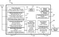
- FIG. 2depicts a circuit layout of a Class-3 chip 200 according to an illustrative embodiment for implementation in an RFID tag.
- This Class-3 chipcan form the core of RFID chips appropriate for many applications such as identification of pallets, cartons, containers, vehicles, or anything where a range of more than 2-3 meters is desired.
- the chip 200includes several industry-standard circuits including a power generation and regulation circuit 202 , a digital command decoder and control circuit 204 , a sensor interface module 206 , a C1G2 interface protocol circuit 208 , and a power source (battery) 210 .
- a display driver module 212can be added to drive a display.
- a battery activation circuit 214is also present to act as a wake-up trigger. In brief, many portions of the chip 200 remain in hibernate state during periods of inactivity. A hibernate state may mean a low power state, or a no power state. The battery activation circuit 214 remains active and processes incoming signals to determine whether any of the signals contain an activate command. If one signal does contain a valid activate command, additional portions of the chip 200 are wakened from the hibernate state, and communication with the interrogator can commence. In one embodiment, the battery activation circuit 214 includes an ultra-low-power, narrow-bandwidth preamplifier with an ultra low power static current drain.
- the battery activation circuit 214also includes a self-clocking interrupt circuit and uses an innovative user-programmable digital wake-up code.
- the battery activation circuit 214draws less power during its sleeping state and is much better protected against both accidental and malicious false wake-up trigger events that otherwise would lead to pre-mature exhaustion of the Class-3 tag battery 210 . While any type of battery activation circuit known in the art can be potentially integrated into the system, an illustrative battery activation circuit 214 is described in copending U.S. patent application Ser. No. 11/007,973 filed Dec. 8, 2004 with title “BATTERY ACTIVATION CIRCUIT”, which is herein incorporated by reference.
- a battery monitor 215can be provided to monitor power usage in the device. The information collected can then be used to estimate a useful remaining life of the battery.
- a forward link AM decoder 216uses a simplified phase-lock-loop oscillator that requires an absolute minimum amount of chip area. Preferably, the circuit 216 requires only a minimum string of reference pulses.
- a backscatter modulator block 218preferably increases the backscatter modulation depth to more than 50%.
- a memory celle.g., EEPROM
- a pure, Fowler-Nordheim direct-tunneling-through-oxide mechanism 220is present to reduce both the WRITE and ERASE currents to about 2 ⁇ A/cell in the EEPROM memory array. Unlike any RFID tags built to date, this will permit designing of tags to operate at maximum range even when WRITE and ERASE operations are being performed. In other embodiments, the WRITE and ERASE currents may be higher or lower, depending on the type of memory used and its requirements.
- the memoryis preferably present with a capacity sufficient to store several sensor readings and data associated with it such as time, date, etc. as well as provide memory for processing on the chip.
- the module 200may also incorporate a highly-simplified, yet very effective, security encryption circuit 222 .
- Other security schemes, secret handshakes with interrogators, etc.can be used.
- connection pads(not shown) are required for the chip 200 to function: Vdd to the battery, ground, plus two antenna leads to support multi-element omni-directional and isotropic antennas. Sensors to monitor temperature, shock, tampering, etc. can be added by appending an industry-standard I 2 C or SPI interface to the core chip.
- ASICsApplication Specific Integrated Circuits
- FPGAsField Programmable Gate Arrays
- the inventioncan also be provided in the form of a computer program product comprising a computer readable medium having computer code thereon.
- A. computer readable mediumcan include any medium capable of storing computer code thereon for use by a computer, including optical media such as read only and writeable CD and DVD, magnetic memory, semiconductor memory (e.g., FLASH memory and other portable memory cards, etc.), etc.
- optical mediasuch as read only and writeable CD and DVD, magnetic memory, semiconductor memory (e.g., FLASH memory and other portable memory cards, etc.), etc.
- such softwarecan be downloadable or otherwise transferable from one computing device to another via network, wireless link, nonvolatile memory device, etc.
- a computer for storing and/or executing the code and/or performing the processes described hereincan be any type of computing device, including a personal computer (PC), laptop PC, handheld device (e.g., personal digital assistant (PDA)), portable telephone, etc.
- PCpersonal computer
- laptop PClaptop PC
- handheld devicee.g., personal digital assistant (PDA)
- portable telephoneetc.
- REID tagsmay be coupled to objects, each tag being associated with and optionally storing information about the object to which coupled.
- a tagged objectcan be identified and located by identifying and locating the tag coupled to it.
- FIG. 3illustrates a semi-passive (or active) RFID tag 300 with display device and sensor capability such that an environmental condition-based alarm condition is signaled by a single or multiple bits that trigger a change in color of a color stripe, thereby providing a visual indication that the alarm condition has occurred.
- the tag 300includes one or more sensors 302 , 304 for detecting one or more environmental conditions.
- the tag 300also includes a visual display device 306 .
- a visual indicatorcan be a simple color change, the placement of a symbol such as a circle or triangle, or can include a number of textual or graphical representations.
- the tag 300can be attached to an item utilizing numerous mechanisms. For example, conventional mechanical fastening system, loop and hook-type arrangements, stitches, adhesives, as well as other known fixation techniques may be employed to permanently or temporarily attach the tag 300 to an item.
- the tag 300can also be integrally formed with the item, or can be used as a stand alone device.
- the sensors 302 , 304monitor the external environment in which the tag 300 is operating. Virtually any environmental condition can be monitored. Illustrative sensors monitor temperature, humidity, Ph, sunlight, ultraviolet light, chemicals, radioactivity, pathogens, bacteria, viruses, prions, carbon dioxide level, etc. in the environment surrounding the tag 300 . Alarm conditions can be based on exceeding levels or quantities, such as passing a threshold high temperature, falling below a threshold low temperature, or detecting a certain number of viruses. Alarm conditions can also be based on historic data, such as a number of hours that the carbon dioxide level was above a threshold. For example, in one embodiment an internal or external temperature sensor can be employed so that in the event that the tag 300 experiences a period below freezing, a visual indicator on the visual display 306 will be on display to a user, who can quickly ascertain that an alarm condition has occurred.
- One or more of the sensorscan also monitor a condition, e.g., characteristic or property, of the item to which attached, as opposed to an environmental condition.
- a conditione.g., characteristic or property
- One exampleincludes monitoring a surface temperature of the object to which attached.
- the sensors 302 , 304may take readings continuously, or may take readings at some interval, such as every 5 minutes, every hour, etc.
- the tagmay enter a hibernate state during the interval period between readings to conserve battery power.
- a controller 308 on the tagis coupled to the sensors 302 , 304 and sets an alarm state based on output from one (or more) of the sensors.
- the controller 308controls the activation of the visual display device 306 upon detecting the Examples of operation will be provided below.
- the controller 308may include one or more silicon chips, programmable microcontrollers or discrete components.
- the controllercan set an alarm flag to indicate the alarm condition.
- the alarm flagis one or more bits stored in memory on the tag. A logic zero indicates a normal condition, while logic one indicates an active alarm state (or vice versa). The flag preferably remains set until reset by an authorized entity .
- the visual indicator of the visual display device 306remains present on the visual display device 306 either permanently, or until the tag receives an instruction to revert to a non-alarm state from an authorized entity.
- An authorized entitymay be the end recipient of goods previously in transit, a system administrator, a security service, a computerized system, etc.
- Validation of the authorized entity by the tag 300can be based on receipt of a password or secret code for example. By only allowing an authorized entity to disengage the alarm state, tampering with the tag is prevented. Also, because the ID of the tag is known and associated with a certain object, the tag cannot merely be replaced with another tag not displaying the alarm condition visual indicator. Accordingly, upon a tagged item arriving at its destination, the tag may be scanned to verify its identity, e.g., by comparing the tags EPC to the EPC shown on a shipping order.
- the visual display device 306can be any type of display device.
- Illustrative visual display devicesinclude color-changing strips, electrophoretic displays, electrokinetic displays, light emitting diodes (LEDs), liquid crystal displays (LCDs), etc.
- LEDslight emitting diodes
- LCDsliquid crystal displays
- One practicing the inventionwill understand that the type of visual display device 306 used will depend on the power supply to the tag. If the tag has a virtually unlimited power supply, e.g., is coupled to a vehicle battery, then visual display devices using higher power may be used. If the tag has a limited power supply, e.g. , onboard battery, low power visual display devices such as state changing electrochemical stips are preferred.
- the visual display device 306is an ultra-low power display device, so as to use as little battery power as possible and thereby maximize the active life of the tag 300 (the tag may remain useful as a passive tag after the battery is expended).
- the visual display device 306is preferably one that continues to display the visual indicator even after power to the display device is removed. This minimized power consumption, which is of particular importance for RFID tags of limited battery life.
- a preferred visual display device 306includes a chemical strip that changes color upon receiving an electrical signal from the controller 308 . The color change is permanent until reset electronically by the controller 308 , and does not require a continuous electric current to maintain the color change.
- the display media of the visual display device 306can be a bi-stable, non-volatile display medium.
- bi-stable non-volatile mediumsinclude but are not limited to encapsulated and un-encapsulated electrophoretic material, Cholesteric materials, polymer dispersed cholesteric liquid crystals (PDChLC), encapsulated cholesteric materials, separated redox and dye reaction materials such as Dow Commotion.RTM. display medium, ph sensitive dyes, electrothermochromics displays and thermo-chromic, zenithal hi-stable, nematic, and surface stabilized ferroelectric liquid crystals.
- the display mediacan further comprise electronic ink, wherein the electronic ink is capable of displaying a graphical indicator on the electronic label.
- electronic inkas used herein is intended to include any suitable bi-stable, non-volatile material.
- bi-stableas used herein is intended to indicate that the particles of the imaging material can alternately occupy two stable states. For example, the particles corresponding to different pixel locations of the display assembly can alternately occupy an ON or an OFF state to form selected indicia.
- the display mediais reflective to provide a greater viewing angle to the image displayed by the electronic label.
- the particles in the imaging materialcan be oriented in a first state to reflect light (ON) or a second state to absorb light (OFF).
- the term “non-volatile” as used hereinis intended to denote that the imaging material has indefinite memory without power and will retain an image in the absence of power to the visual display device 306 .
- the particles in the imaging materialmaintain a first state unless actively directed to change to a second state.
- the imaging surface of the labelshows a high-quality image even when power to the visual display device 306 is turned off.
- the electronic inkcan also be a printable, conductive ink having an arrangement of particles or microscopic containers or microcapsules.
- Each microcapsulehas disposed therein an electrophoretic composition of a fluid, such as a dielectric or emulsion fluid, and a suspension of colored or charged particles or colloidal material.
- the diameter of the microcapsulestypically ranges from about 30 to about 300 microns.
- the particlesvisually, contrast with the dielectric fluid.
- the electronic inkcan include rotatable balls that can rotate to expose a different colored surface area, and which can migrate between a forward viewing position and/or a rear non-viewing position, or both.
- a gyriconis a material comprised of twisting rotating elements contained in liquid-filled spherical cavities and embedded in an elastomer medium. The rotating elements can be made to exhibit changes in optical properties by the imposition of an external electric field. Upon application of an electric field of a given polarity, one segment of a rotating element rotates toward, and is visible by an observer of the display.
- Gyricon displaymaintains a given configuration until an electric field is actively applied to the display assembly.
- Gyricon particlestypically have a diameter of about 100 microns. Gyricon materials are disclosed in U.S. Pat. Nos. 6,147,791, 4,126,854 and 6,055,091, the contents of which are herein incorporated by reference.
- a reference electrode layercan be used in co conjunction with the electronic ink disposed upon a display medium and a backplane to form an electronically activatable and addressable electronic display.
- the electrode and backplanecan be disposed on, or cover opposite sides of the microcapsule arrangement, or both to provide structure for creating a potential difference across the electronic ink that causes particles within the microcapsules to migrate toward one of the electrodes. This migration can change the color of the sphere, and hence the pixel location, as viewed by an individual.
- the microcapsulescan be filled with electrically charged white particles in a black or colored dye.
- the term electronic inkcan also include a bi-stable non-volatile cholesteric imaging material.
- the cholesteric liquid crystal materialhas positive dielectric anisotropy and can include a chiral material in an amount effective to form focal conic and twisted planar textures.
- cholesteric imaging materialcomprises liquid crystal cells ranging in thickness from about 25 microns to about 50 microns. Suitable cholesteric materials are disclosed for example in U.S. Pat. Nos. 6,154,190, 6,061,107 and 5,847,798, the contents of which are incorporated herein by reference.
- the electronic inkcan include zenithal bi-stable display technology to form the bi-stable nonvolatile display assembly comprised of a bi-stable nematic liquid crystal device cell.
- the bi-stable nematic cellis provided with a surface alignment grating on at least one cell wall and a surface treatment on an opposite cell wall.
- the materialis activated by DC pulses to form an image.
- Suitable zenithal bi-stable devicesare disclosed in U.S. Pat. No. 6,151,096, International Patent Application Publication Number WO 98/04953, International Patent Application Publication Number WO 99/34251A1, U.S. Pat. No. 6,054,973, International Patent Application Publication Number WO 00/52671, and U.S. Pat. No. 6,151,096, the contents of which are herein incorporated by reference.
- thermo-chromic materialis capable of changing its state alternately between transparent and opaque upon the application of heat. In this manner, a thermo-chromic imaging material develops images through the application of heat at specific pixel locations in order to form an image. The thermo-chromic imaging material retains a particular image until heat is again applied to the material.
- the display assemblyis reusable, rewritable, non-volatile, bi-stable. Visually, black characters are written in a transparent background by applying heat to selected locations or pixels in the display layer. To form color displays other colors, such as red, yellow, and blue are used. Since the rewritable material is transparent, UV fluorescent printings, designs and patterns underneath can be seen through.
- the electronic inkcan also include surface stabilized ferroelectric liquid crystals (SSFLC).
- SSFLCsurface stabilized ferroelectric liquid crystals
- SSFLCsurface stabilized ferroelectric liquid crystals confining ferroelectric liquid crystal material between closely-spaced glass plates to suppress the natural helix configuration of the crystals. The cells switch rapidly between two optically distinct, stable states simply by alternating the sign of an applied electric field.
- Magnetic particles suspended in an emulsioncomprise an additional imaging material suitable for use with the present invention.
- Application of a magnetic forcealters pixels formed with the magnetic particles in order to create, update or change human readable indicia, machine readable indicia or both.
- Those skilled in the artwill recognize that a variety of bi-stable non-volatile imaging materials are available and may be implemented in the present invention.
- the RFID tag 300 of FIG. 3 and other embodiments disclosed hereinmay include other features, such as data logging, etc.
- FIG. 4illustrates a tag 400 that sets an alarm state upon detecting an exception.
- the tag 400includes a visual display device 402 .
- an alarm stateis set and the visual display device 402 is instructed or engaged to display a visual indicator of the alarm condition. For example, if the tag goes out of range of the reader, the lack of incoming signal creates an exception and the alarm state is set. Similarly, if the tag realizes it has passed by a reader without being detected (e.g., was shielded but now detects a signal), an alarm state can be set.
- the visual display devicemay also include a mechanical device, which may include some electronic components but has a mechanical aspect.
- FIGS. 5A-5Billustrate a tag 500 where the visual display device 502 includes a mechanical flag 504 .
- the mechanical flag 504is retracted so that a particular color is shown in the window 506 .
- a trigger 508releases the flag 504 , which is carried into the window 506 via spring 510 .
- the flag 504changes the color viewed through the window.
- the flag 504can be mechanically reset e.g., by insertion of a tool through an opening, etc.
- the trigger 508can remain retracted until the tag 500 is instructed to actuate the trigger 508 .
- the flag 504may lock into place upon being released.
- a lock 512may be provided for this purpose and may or may not be selectively releasable.
- FIG. 6illustrates a tag 600 having a tactile indicator 602 that indicates an alarm condition.
- the tactile indicator 602 in this embodimentincludes a button 604 that pops out of the tag.
- the button 604can then be felt by a user.
- the button 604may also be visible, and may have a color different than that of the tag housing.
- the tactile indicator 602may include a trigger and spring mechanism similar to that used in the illustrative tag 500 of FIGS. 5A-5B .
- Embodiments with tactile indicatorsare particularly useful for monitoring items or conditions where a direct line of sight to the tag is difficult, such as between boxes of goods, under pallets, inside pipes, etc. Note that the tactile indicator can be provided in addition to a visual device, or can replace it.
- the alarm stateis set by an interrogator upon the interrogator detecting an alarm condition, e.g., upon occurrence of some event. For example, if the interrogator detects an unauthorized ID badge, it may instruct that badge to set the alarm condition.
- the interrogatorsets an alarm state in each tag as it identifies each tag to indicate which tags have been read, are from a certain lot, are coupled to objects to be identified, etc.
- an audible output devicecan be any type of audible output device known in the art, such as a buzzer, speaker outputting a beep, etc.
- the audible devicemay provide similar functionality as the visual or tactile device, such as persistent output until reset, etc.
- variations of the present inventionmay include combinations of the various types of output/indicator devices, multiples of the same type of output device, etc.
- FIG. 7graphically depicts an illustrative method 700 for visually and electronically indicating occurrence of an alarm condition.
- an alarm conditionis detected. This operation may be performed by the tag, the interrogator, or both.
- An alarm stateis set upon detecting the alarm condition in operation 704 .
- a visual indicator of the alarm conditionis generated.
- a tactile indicatoris also initiated. At this point, a user can see or feel that an alarm condition has occurred or is occurring.
- an electronic queryis received from an RFID interrogator.
- An electronic indication of the alarm conditionis transmitted to the interrogator in operation 712 .
- the visual and/or tactile indicator of the alarm conditioncan only be reset by an authorized entity. Accordingly, in operation 714 , authorization of the entity is verified. If the entity is authorized, the alarm state is reset in operation 716 . The indicator may then reflect or be reset to a non-alarm condition. If the entity is not authorized, the alarm state is not reset and the visual and/or tactile indicator remain in the alarm state.
- the tagmay also transmit the electronic indication of the alarm condition to the interrogator without having first received a query from the interrogator.
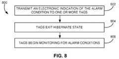
- FIG. 8depicts a method 800 for activating other RFID tags on occurrence of an alarm condition.
- a master tagtransmits an electronic indication of an alarm condition to one or more other tags. This transmission may include an activate command to bring the other tags out of a hibernate state. The transmission may include a simple instruction to begin monitoring. The transmission may also include the nature of the alarm condition, as well as parameters for detecting alarm conditions by the various other tags.
- the other tag(s)come out of a hibernate state, and in operation 806 , begin monitoring for alarm condition (which may or may not be the same as the first alarm condition).
- a transmissionis meant to include a series of transmissions between the tags, with possible transmissions to and from an interrogator. For example, in a variation, the master tag might transmit the indicator of the alarm condition to the interrogator, and the interrogator wakes the other tags. Also, the master tag and/or other tags may or may not have a visual display device or tactile device thereon.
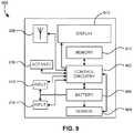
- FIG. 9illustrates an RFID tag 900 according to another embodiment of the present invention.
- the tag 900includes a controller 902 , a sensor 904 in communication with the controller 902 , a local power source, e.g., battery, 906 for providing power to the controller 902 , an antenna 908 in communication with the controller 902 , memory 910 in communication with the controller, a display device 912 , and one or more user input devices 914 for receiving manual input from a user.
- the controller 902 , sensor 904 , a local power source 906 , antenna 908 , memory 910 , and display device 912can be similar or identical to those described above, and some of which may be integrated into the same chip as the controller.
- a function of the tag 900is selectable by manipulation of the user input device(s) 914 .
- the tag 900(or portion thereof) can be manually started by the user via the user input device(s) 914 . This encompasses not only initializing a completely powered-down tag 900 , but more likely, waking the tag 900 from a low power hibernate state into an active state e.g., battery powered state.
- the tag 900may include activate circuitry 916 as a separate module or integrated into the controller 902 .
- the activate circuitry 916detects a valid activate command in an incoming RF signal and causing the tag 900 to wake from a hibernate state. Because the user may not always have an interrogator present, manipulation of the user input device may also cause the controller 902 to wake from the hibernate state, either via the activate circuitry 916 or other mechanism.
- other functionsbecome accessible, such as manually requesting a sensor 904 reading via the user input device(s) 914 .
- the activate circuitry 916may be in a powered down initial state, where a signal from a user input device causes initialization of at least the activate circuitry 916 .
- Active and semi-passive tagsdo not have infinite battery life. Rather, the life of the battery will depend on many things, including when the tag 900 was first powered, the amount of time that the tag 900 is active, which functions the tag 900 is performing and how frequently, etc.
- the tag 900is immediately activated, optionally programmed with an EPC, and placed into a hibernate mode. Thereafter, battery power is constantly being drawn to power the activate circuitry 916 , which monitors incoming signals for a valid activate command.
- One embodiment of the present inventionis a tag 900 that is completely powered down. Then, upon receiving a manual user input, at least the activate circuitry 916 is initialized so that an interrogator can communicate with the tag 900 . The activate circuitry 916 on the tag 900 may remain active thereafter, powering down again only upon receiving a valid instruction to do so from an interrogator or via user input. Preferably, whether the instruction is valid depends on a security scheme, e.g., using a code or password stored in the tag. 900 , and which is compared to an incoming (wirelessly or manually entered) code or password.
- Many functionsmay be initiated by manipulation of the user input device(s) 914 .
- One such functionis taking a one-time reading by the sensor 904 . This is useful, for example, where the scheduled sensor 904 reading interval is large, and the user wants to take a manual reading.
- the sensor 904takes a one-time reading by the sensor 904 . This is useful, for example, where the scheduled sensor 904 reading interval is large, and the user wants to take a manual reading.
- the scheduled sensor 904 reading intervalis large, and the user wants to take a manual reading.
- Another manually selectable functionis requesting output of a reading of the sensor 904 , such as a current reading, a maximum reading or a minimum reading of the sensor 904 .
- the functionmay be causing output of a historical compilation based on readings of the sensor 904 .
- the usercan manually select from a sub-set of pre-programmed modes using the user input device(s) 914 .
- the user input device(s) 914may toggle initialization of the sensor 904 and/or a data gathering mode.
- a further functionis alteration of parameters of such a mode.
- the user input device(s) 914can be used to set parameters of the sensors 904 in a data gathering mode, such as setting upper and lower alarm condition limits on whatever is being monitored by the sensor 904 .
- the tag 900includes a visual or audible mechanism for indicating which function or mode the user is starting.
- the tag 900has a display device 912 .
- the display device 912can output alphanumeric indication of which mode the user is in.
- the display device 912can also output data stored in memory 910 , e.g., sensor 904 readings. If the display device 912 is merely a flashing light, the tag 900 can flash the light each time the mode changes. If no display device 912 is present, the tag 900 may include a device for generating audible tone, such that a tone is emitted each time the mode changes. Sequences of flashes or tones can also indicate which mode is currently selected or active. For example one flash or beep indicates the tag 900 is operating in a first mode, two flashes or beeps indicates that the tag 900 is operating in a second mode, and so on.
- Data stored on the tag 900may be displayed upon manipulation of the user input device(s) 914 .
- high and low sensor 904 readingscan be displayed, as well as historical values.
- Other information stored in the memory 910can also be displayed, such as the tag ID, product ownership information, etc. Note that access to some data stored on the tag 900 may be limited when a user accesses the data manually (e.g., a reader is not present).
- a pass codemay be required to access some data. The pass code can be entered via the user input device(s) 914 .
- the display device 912may further provide a visual indicator of occurrence of an alarm condition, as discussed in detail above.
- Some embodimentsmay allow the user to set alarm condition settings manually. If so, a security mechanism should be implemented such as requiring a user to enter a password to change alarm condition settings.
- the security mechanismprevents tampering with the alarm condition settings.
- An example of tamperingis raising a maximum allowable temperature setting to above an acceptable limit during part of a transportation process in order to ensure that the alarm condition never occurs.
- other functionssuch as reviewing sensor 904 readings, requesting additional sensor 904 readings, viewing identification information, etc. may be allowed without security.
- Illustrative user input devices 914include buttons, wheels, keys, levers, etc. and combinations thereof.
- the tag 900has only one button, which allows selection of a mode of operation. Modes are selected by pressing the single button repeatedly until the desired mode is reached. Which mode is currently selected can be displayed on the display device 912 of the tag 900 , for example. Further, parameters of a particular mode can be manipulated by selecting a desired mode, then holding down the button to enter a configuration mode.
- the tag 900has two buttons. Depressing either button wakes the tag 900 . Then, three modes can be selected by pressing the first button and not the second button, the second button and not the first button, and both buttons together.
- buttonscan allow scrolling between selectable modes or instructions on the display device 912 , or one button may scroll forward through display items and the other button selects the mode or instruction being displayed.
- one buttonmay scroll forward through display items and the other button selects the mode or instruction being displayed.
- FIG. 10illustrates a method 1000 for performing a function, such as taking a sensor reading, upon receiving manual user input according to one embodiment of the present invention.
- operation 1002manipulation of a user input device is detected.
- the tagis awakened from a hibernate mode in operation 1004 . In other words, certain circuitry of the tag is energized and initiated.
- operation 1006a display device outputs an indication of a currently active or selectable function or mode.
- signals from the user input deviceis detected. The signals from the user input device are interpreted to determine whether the currently-output function has been selected by the user at decision 1010 .
- an indication of a different function or modeis selected for output in operation 1012 , and operations 1006 - 1010 are repeated.
- the functionis performed in operation 1014 .
- One illustrative functionis taking a sensor reading. Another is outputting a reading of the sensor.
- decision 1016a determination is made as to whether additional functions are desired. For instance, receiving additional user input may indicate that further functions are desired. On the contrary, user input or lack thereof for a predetermined period of time, e.g., 20 seconds, may indicate that no additional functions are desired. If no additional functions are desired, the tag reverts to a hibernate state in operation 1018 . If additional functions are desired, the process returns to operation 1012 .
- a tagis coupled to a case of frozen meat.
- the tagincludes a temperature sensor and an alarm as described herein.
- the tagrecords a temperature profile of the temperature in the case. Readings can be taken at any desired interval from seconds to days, e.g., every 15 minutes, every hour, every three hours, etc.
- the frequencymay depend on user preference, the sensitivity of the item(s) being monitored, the susceptibility to temperature change, etc. For example, frozen goods temperature does not change very rapidly in at dense and packed environment, and so longer intervals may be suitable.
- a flagis set and the visual alarm is engaged.
- the visual indicatorallows people to quickly verify whether the goods have been damaged without requiring that a tag reader be present. If the temperature of the case of meat has exceeded the maximum value, the visual alarm will indicate that the recipient should reject the meat, or at least review the temperature profile stored on the tag prior to accepting the product.
- a blood bagis being transported from a blood bank to a hospital.
- a tagis attached to the blood bag, and programmed to set an alarm state if the blood bag exceeds 50 degrees F. for a period of 5 minutes. If the blood bag exceeds 50 degrees F., a stripe on the tag changes color from blank to red. “Blank” refers to a default color and can be any color. For the present description, assume blank is black. The visual indicator allows people to quickly verify whether the blood has been damaged without requiring that a tag reader be present.
- a rack of wineis stored in a cellar.
- a tagis attached to the rack of wine, and programmed to set an alarm state if the UV light in the cellar reaches a cumulative amount since the tag was placed, e.g., 5 million photons. If the cellar exceeds the threshold, the alarm condition flag is set and a visual indicator is displayed, e.g., a stripe on the tag changes color from green to red.
- the tags that have been readare set to the alarm state and so display a visual indicator. Those not yet read do not display a visual indicator.
- a tag having a moisture sensor and a tactile indicatoris coupled to the underside of a wood pallet.
- the palletis then loaded with cases of products.
- the tagis programmed to set an alarm state if the moisture sensor gets wet. When water is splashed on or rises to the level of the moisture sensor, the alarm flag is set and the tactile indicator extends from the tag. A user reaches under the pallet and touches the tag to feel if the tactile indicator is extended. If so, at least the bottom of the pallet was in contact with water.
- a master tag having a temperature sensoris placed on the outside of a pallet stacked with goods. Tags having temperature sensors are coupled to cases of items on the pallet.
- the master tagis programmed to set an alarm state if the ambient temperature exceeds a threshold. When temperature exceeds the threshold, the master tag alarm flag is set and an activate command is sent to the tags on the pallet.
- the tagswake up and begin monitoring a temperature profile of the object to which attached or its environment.
- An item in a refrigerated roomis tagged with an RFID tag having a temperature sensor.
- the tagis preprogrammed to wake from a hibernate state to take a temperature reading every 30 minutes. Days later, a user wants to observe a historical temperature profile of the tagged item in the refrigerated room. The user does not have a reader handy, so he manipulates user input devices to view current status, historical temperature profile, interval between readings, etc.
- a tagis coupled to a case of temperature-sensitive goods being shipped across the country in a refrigerated truck.
- the trackarrives at its destination, a small grocery store.
- the grocery store employeein charge of receiving the goods wants to verify that the case of goods did not exceed a preset threshold temperature.
- the employeedoes not have an RFID reader handy, and so the employee manipulates the user input devices on the tag to retrieve the maximum and minimum temperatures of the case (or its environment) during transportation.
- the employeecan also review and verify the upper and lower temperature thresholds programmed into the tag. In this way, the user need not have an operating interrogator in hand to determine whether to accept or reject the goods.
- the truck drivercan also check the temperature profile of the goods prior to accepting them on his truck, as well as anytime during shipment.
Landscapes
- Engineering & Computer Science (AREA)
- Physics & Mathematics (AREA)
- General Physics & Mathematics (AREA)
- Computer Hardware Design (AREA)
- Microelectronics & Electronic Packaging (AREA)
- Theoretical Computer Science (AREA)
- Artificial Intelligence (AREA)
- Computer Vision & Pattern Recognition (AREA)
- Radar Systems Or Details Thereof (AREA)
- Near-Field Transmission Systems (AREA)
Abstract
Description
- 1. Header, which identifies the length, type, structure, version and generation of EPC;
- 2. Manager Number, which identifies the company or company entity;
- 3. Object Class, similar to a stock keeping unit or SKU; and
- 4. Serial Number, which is the specific instance of the Object Class being tagged.
Additional fields may also be used as part of the EPC in order to properly encode and decode information from different numbering systems into their native (human-readable) forms.
- Class-1
- Identity tags (RF user programmable, range ˜3 m)
- Lowest cost
- Class-2
- Memory tags (20 bit address space programmable at ˜3 m range)
- Security & privacy protection
- Low cost
- Class-3
- Semi-passive tags (also called semi-active tags)
- Battery tags (256 bits to 2M words)
- Self-Powered Backscatter (internal clock, sensor interface support)
- ˜100 meter range
- Moderate cost
- Class-4
- Active tags
- Active transmission (permits tag-speaks-first operating modes)
- ˜30,000 meter range
- Higher cost
- Class-1
Claims (47)
Priority Applications (2)
| Application Number | Priority Date | Filing Date | Title |
|---|---|---|---|
| US11/423,699US7796038B2 (en) | 2006-06-12 | 2006-06-12 | RFID sensor tag with manual modes and functions |
| PCT/US2007/013186WO2007145911A2 (en) | 2006-06-12 | 2007-06-04 | Rfid sensor tag with manual modes and functions |
Applications Claiming Priority (1)
| Application Number | Priority Date | Filing Date | Title |
|---|---|---|---|
| US11/423,699US7796038B2 (en) | 2006-06-12 | 2006-06-12 | RFID sensor tag with manual modes and functions |
Publications (2)
| Publication Number | Publication Date |
|---|---|
| US20070285238A1 US20070285238A1 (en) | 2007-12-13 |
| US7796038B2true US7796038B2 (en) | 2010-09-14 |
Family
ID=38821322
Family Applications (1)
| Application Number | Title | Priority Date | Filing Date |
|---|---|---|---|
| US11/423,699Active2028-03-18US7796038B2 (en) | 2006-06-12 | 2006-06-12 | RFID sensor tag with manual modes and functions |
Country Status (2)
| Country | Link |
|---|---|
| US (1) | US7796038B2 (en) |
| WO (1) | WO2007145911A2 (en) |
Cited By (22)
| Publication number | Priority date | Publication date | Assignee | Title |
|---|---|---|---|---|
| US20080074254A1 (en)* | 2006-09-07 | 2008-03-27 | Townsend Christopher P | Heat stress, plant stress and plant health monitor system |
| US20090102660A1 (en)* | 2007-09-24 | 2009-04-23 | Savi Technology, Inc. | Method and Apparatus for Tracking and Monitoring Containers |
| US20090278747A1 (en)* | 2006-09-07 | 2009-11-12 | Tareef Ibrahim Al-Mahdawi | Rfid device with microstrip antennas |
| US20090322472A1 (en)* | 2008-06-30 | 2009-12-31 | Macdonald Mark | Temperature measurement in electronic devices |
| US20100090809A1 (en)* | 2007-03-14 | 2010-04-15 | Junho Yeo | Method and apparatus for transmitting sensor status of radio frequency identification tag |
| US20110037589A1 (en)* | 2009-08-11 | 2011-02-17 | Rong Zhi Xin Science and Technology Development (Beijing) Co., Ltd. | Wireless monitoring system and method |
| US20110046889A1 (en)* | 2009-08-19 | 2011-02-24 | Donald Ray Bryant-Rich | Environmental monitoring system for canines, felines, or other animals |
| US20120044055A1 (en)* | 2009-01-07 | 2012-02-23 | Kosta Kovacic | Method for a secure non-volatile logging in an active rfid tag of a process in a tagged article |
| US20130103900A1 (en)* | 2011-10-21 | 2013-04-25 | Getac Technology Corporation | Electronic system and method and apparatus for saving data thereof |
| US20150116093A1 (en)* | 2013-10-30 | 2015-04-30 | Massachusetts Institute Of Technology | Chemical and physical sensing with a reader and rfid tags |
| US9030295B2 (en) | 2013-02-21 | 2015-05-12 | International Business Machines Corporation | RFID tag with environmental sensor |
| US9775095B2 (en) | 2015-06-18 | 2017-09-26 | Carrier Corporation | Aircraft proximity sensor system for radio frequency transmission device |
| US10089567B2 (en) | 2016-12-15 | 2018-10-02 | At&T Intellectual Property I, L.P. | Method and apparatus for providing a communications service using a low powered radio tag |
| WO2019109087A1 (en)* | 2017-12-01 | 2019-06-06 | Metrc, Llc | System and method for programming wireless sensor tags in food service operations |
| US10466111B2 (en) | 2016-05-05 | 2019-11-05 | Walmart Apollo, Llc | Systems and methods for monitoring temperature or movement of merchandise |
| US11070895B2 (en) | 2014-12-31 | 2021-07-20 | Walmart Apollo, Llc | System and method for monitoring gas emission of perishable products |
| US11138554B2 (en) | 2017-05-23 | 2021-10-05 | Walmart Apollo, Llc | Automated inspection system |
| US11388325B2 (en) | 2018-11-20 | 2022-07-12 | Walmart Apollo, Llc | Systems and methods for assessing products |
| US11393082B2 (en) | 2018-07-26 | 2022-07-19 | Walmart Apollo, Llc | System and method for produce detection and classification |
| US11448632B2 (en) | 2018-03-19 | 2022-09-20 | Walmart Apollo, Llc | System and method for the determination of produce shelf life |
| US11715059B2 (en) | 2018-10-12 | 2023-08-01 | Walmart Apollo, Llc | Systems and methods for condition compliance |
| US12175476B2 (en) | 2022-01-31 | 2024-12-24 | Walmart Apollo, Llc | Systems and methods for assessing quality of retail products |
Families Citing this family (151)
| Publication number | Priority date | Publication date | Assignee | Title |
|---|---|---|---|---|
| US7811231B2 (en) | 2002-12-31 | 2010-10-12 | Abbott Diabetes Care Inc. | Continuous glucose monitoring system and methods of use |
| US7587287B2 (en) | 2003-04-04 | 2009-09-08 | Abbott Diabetes Care Inc. | Method and system for transferring analyte test data |
| US7864053B2 (en)* | 2006-04-12 | 2011-01-04 | Visible Assets, Inc. | Visibility radio cap and network |
| US20100033330A1 (en)* | 2003-04-09 | 2010-02-11 | Visible Assets, Inc. | Auditable security for cargo containers and other repositories |
| US7679407B2 (en) | 2003-04-28 | 2010-03-16 | Abbott Diabetes Care Inc. | Method and apparatus for providing peak detection circuitry for data communication systems |
| WO2005089103A2 (en) | 2004-02-17 | 2005-09-29 | Therasense, Inc. | Method and system for providing data communication in continuous glucose monitoring and management system |
| WO2005086802A2 (en) | 2004-03-08 | 2005-09-22 | Proxense, Llc | Linked account system using personal digital key (pdk-las) |
| EP1810185A4 (en) | 2004-06-04 | 2010-01-06 | Therasense Inc | Diabetes care host-client architecture and data management system |
| EP1829283A2 (en) | 2004-12-20 | 2007-09-05 | Proxense, LLC | Biometric personal data key (pdk) authentication |
| US8029441B2 (en) | 2006-02-28 | 2011-10-04 | Abbott Diabetes Care Inc. | Analyte sensor transmitter unit configuration for a data monitoring and management system |
| US9788771B2 (en) | 2006-10-23 | 2017-10-17 | Abbott Diabetes Care Inc. | Variable speed sensor insertion devices and methods of use |
| US8231573B2 (en) | 2005-02-01 | 2012-07-31 | Intelliject, Inc. | Medicament delivery device having an electronic circuit system |
| US8206360B2 (en) | 2005-02-01 | 2012-06-26 | Intelliject, Inc. | Devices, systems and methods for medicament delivery |
| US9022980B2 (en) | 2005-02-01 | 2015-05-05 | Kaleo, Inc. | Medical injector simulation device |
| AU2006210865B2 (en) | 2005-02-01 | 2008-12-04 | Kaleo, Inc. | Devices, systems, and methods for medicament delivery |
| US8361026B2 (en) | 2005-02-01 | 2013-01-29 | Intelliject, Inc. | Apparatus and methods for self-administration of vaccines and other medicaments |
| US7768408B2 (en) | 2005-05-17 | 2010-08-03 | Abbott Diabetes Care Inc. | Method and system for providing data management in data monitoring system |
| JP2009507224A (en) | 2005-08-31 | 2009-02-19 | ユニヴァーシティー オブ ヴァージニア パテント ファンデーション | Improving the accuracy of continuous glucose sensors |
| US7583190B2 (en) | 2005-10-31 | 2009-09-01 | Abbott Diabetes Care Inc. | Method and apparatus for providing data communication in data monitoring and management systems |
| US8219129B2 (en) | 2006-01-06 | 2012-07-10 | Proxense, Llc | Dynamic real-time tiered client access |
| US11206664B2 (en) | 2006-01-06 | 2021-12-21 | Proxense, Llc | Wireless network synchronization of cells and client devices on a network |
| US8219173B2 (en) | 2008-09-30 | 2012-07-10 | Abbott Diabetes Care Inc. | Optimizing analyte sensor calibration |
| US9392969B2 (en) | 2008-08-31 | 2016-07-19 | Abbott Diabetes Care Inc. | Closed loop control and signal attenuation detection |
| US9326709B2 (en) | 2010-03-10 | 2016-05-03 | Abbott Diabetes Care Inc. | Systems, devices and methods for managing glucose levels |
| US7801582B2 (en) | 2006-03-31 | 2010-09-21 | Abbott Diabetes Care Inc. | Analyte monitoring and management system and methods therefor |
| US7620438B2 (en) | 2006-03-31 | 2009-11-17 | Abbott Diabetes Care Inc. | Method and system for powering an electronic device |
| US9675290B2 (en) | 2012-10-30 | 2017-06-13 | Abbott Diabetes Care Inc. | Sensitivity calibration of in vivo sensors used to measure analyte concentration |
| US8478557B2 (en) | 2009-07-31 | 2013-07-02 | Abbott Diabetes Care Inc. | Method and apparatus for providing analyte monitoring system calibration accuracy |
| WO2007127948A2 (en) | 2006-04-27 | 2007-11-08 | Sirit Technologies Inc. | Adjusting parameters associated with leakage signals |
| US7904718B2 (en) | 2006-05-05 | 2011-03-08 | Proxense, Llc | Personal digital key differentiation for secure transactions |
| DE102006034810A1 (en)* | 2006-07-27 | 2008-01-31 | Bizerba Gmbh & Co. Kg | Method for checking a time and / or temperature-sensitive indicator |
| EP1905939A1 (en)* | 2006-09-22 | 2008-04-02 | Datamars SA | Access device for pets |
| US8576758B2 (en)* | 2006-09-29 | 2013-11-05 | Lenovo (Beijing) Limited | Remote wake-up system, WWAM module and terminal |
| US8228175B1 (en)* | 2008-04-07 | 2012-07-24 | Impinj, Inc. | RFID tag chips and tags with alternative behaviors and methods |
| US7991514B2 (en)* | 2006-11-07 | 2011-08-02 | Standard Microsystems Corporation | Processor temperature measurement through median sampling |
| US9269221B2 (en) | 2006-11-13 | 2016-02-23 | John J. Gobbi | Configuration of interfaces for a location detection system and application |
| GB0701074D0 (en)* | 2007-01-19 | 2007-02-28 | Syngenta Ltd | System for distributing perishable goods |
| EP2125075A2 (en) | 2007-01-22 | 2009-12-02 | Intelliject, Inc. | Medical injector with compliance tracking and monitoring |
| US20080199894A1 (en) | 2007-02-15 | 2008-08-21 | Abbott Diabetes Care, Inc. | Device and method for automatic data acquisition and/or detection |
| US8123686B2 (en) | 2007-03-01 | 2012-02-28 | Abbott Diabetes Care Inc. | Method and apparatus for providing rolling data in communication systems |
| WO2008130898A1 (en) | 2007-04-14 | 2008-10-30 | Abbott Diabetes Care, Inc. | Method and apparatus for providing data processing and control in medical communication system |
| WO2008130897A2 (en) | 2007-04-14 | 2008-10-30 | Abbott Diabetes Care, Inc. | Method and apparatus for providing data processing and control in medical communication system |
| EP2137637A4 (en) | 2007-04-14 | 2012-06-20 | Abbott Diabetes Care Inc | Method and apparatus for providing data processing and control in medical communication system |
| US10111608B2 (en) | 2007-04-14 | 2018-10-30 | Abbott Diabetes Care Inc. | Method and apparatus for providing data processing and control in medical communication system |
| CA2683953C (en) | 2007-04-14 | 2016-08-02 | Abbott Diabetes Care Inc. | Method and apparatus for providing data processing and control in medical communication system |
| US8461985B2 (en) | 2007-05-08 | 2013-06-11 | Abbott Diabetes Care Inc. | Analyte monitoring system and methods |
| US7928850B2 (en) | 2007-05-08 | 2011-04-19 | Abbott Diabetes Care Inc. | Analyte monitoring system and methods |
| US8456301B2 (en) | 2007-05-08 | 2013-06-04 | Abbott Diabetes Care Inc. | Analyte monitoring system and methods |
| US8665091B2 (en) | 2007-05-08 | 2014-03-04 | Abbott Diabetes Care Inc. | Method and device for determining elapsed sensor life |
| US8444560B2 (en) | 2007-05-14 | 2013-05-21 | Abbott Diabetes Care Inc. | Method and apparatus for providing data processing and control in a medical communication system |
| US8103471B2 (en) | 2007-05-14 | 2012-01-24 | Abbott Diabetes Care Inc. | Method and apparatus for providing data processing and control in a medical communication system |
| US8239166B2 (en) | 2007-05-14 | 2012-08-07 | Abbott Diabetes Care Inc. | Method and apparatus for providing data processing and control in a medical communication system |
| US8600681B2 (en) | 2007-05-14 | 2013-12-03 | Abbott Diabetes Care Inc. | Method and apparatus for providing data processing and control in a medical communication system |
| US8260558B2 (en) | 2007-05-14 | 2012-09-04 | Abbott Diabetes Care Inc. | Method and apparatus for providing data processing and control in a medical communication system |
| US9125548B2 (en) | 2007-05-14 | 2015-09-08 | Abbott Diabetes Care Inc. | Method and apparatus for providing data processing and control in a medical communication system |
| US8560038B2 (en) | 2007-05-14 | 2013-10-15 | Abbott Diabetes Care Inc. | Method and apparatus for providing data processing and control in a medical communication system |
| US10002233B2 (en) | 2007-05-14 | 2018-06-19 | Abbott Diabetes Care Inc. | Method and apparatus for providing data processing and control in a medical communication system |
| US8248212B2 (en) | 2007-05-24 | 2012-08-21 | Sirit Inc. | Pipelining processes in a RF reader |
| AU2008265542B2 (en) | 2007-06-21 | 2014-07-24 | Abbott Diabetes Care Inc. | Health monitor |
| WO2008157820A1 (en) | 2007-06-21 | 2008-12-24 | Abbott Diabetes Care, Inc. | Health management devices and methods |
| US8160900B2 (en) | 2007-06-29 | 2012-04-17 | Abbott Diabetes Care Inc. | Analyte monitoring and management device and method to analyze the frequency of user interaction with the device |
| US8205093B2 (en)* | 2007-06-29 | 2012-06-19 | At&T Intellectual Property I, L.P. | Restricting access to information |
| US8834366B2 (en) | 2007-07-31 | 2014-09-16 | Abbott Diabetes Care Inc. | Method and apparatus for providing analyte sensor calibration |
| CN101896946A (en)* | 2007-11-01 | 2010-11-24 | 杨森制药公众有限公司 | Pharmaceutical supply package |
| US8659427B2 (en) | 2007-11-09 | 2014-02-25 | Proxense, Llc | Proximity-sensor supporting multiple application services |
| US8171528B1 (en) | 2007-12-06 | 2012-05-01 | Proxense, Llc | Hybrid device having a personal digital key and receiver-decoder circuit and methods of use |
| US20090164239A1 (en) | 2007-12-19 | 2009-06-25 | Abbott Diabetes Care, Inc. | Dynamic Display Of Glucose Information |
| US9251332B2 (en) | 2007-12-19 | 2016-02-02 | Proxense, Llc | Security system and method for controlling access to computing resources |
| US20110029413A1 (en)* | 2008-01-31 | 2011-02-03 | Israel Ben-Tzur | Perishable lifetime management system and method |
| WO2009102979A2 (en) | 2008-02-14 | 2009-08-20 | Proxense, Llc | Proximity-based healthcare management system with automatic access to private information |
| US8427316B2 (en) | 2008-03-20 | 2013-04-23 | 3M Innovative Properties Company | Detecting tampered with radio frequency identification tags |
| WO2009126732A2 (en) | 2008-04-08 | 2009-10-15 | Proxense, Llc | Automated service-based order processing |
| EP2283452B1 (en)* | 2008-04-22 | 2014-12-17 | Electronics and Telecommunications Research Institute | Rfid reader, rfid tag, and controlling method thereof |
| USD994111S1 (en) | 2008-05-12 | 2023-08-01 | Kaleo, Inc. | Medicament delivery device cover |
| US8021344B2 (en) | 2008-07-28 | 2011-09-20 | Intelliject, Inc. | Medicament delivery device configured to produce an audible output |
| US8446256B2 (en) | 2008-05-19 | 2013-05-21 | Sirit Technologies Inc. | Multiplexing radio frequency signals |
| US7826382B2 (en) | 2008-05-30 | 2010-11-02 | Abbott Diabetes Care Inc. | Close proximity communication device and methods |
| US20100013599A1 (en)* | 2008-07-16 | 2010-01-21 | Honeywell International Inc. | Smart monitoring and wireless query system and method |
| US9367711B1 (en) | 2008-09-04 | 2016-06-14 | Intelleflex Corporation | Battery assisted RFID tag with square-law receiver and optional part time active behavior |
| US8511555B2 (en)* | 2008-09-12 | 2013-08-20 | William J. Babcock | Tag communication, identification, and tracking apparatus and system |
| US20100127871A1 (en)* | 2008-11-26 | 2010-05-27 | Pontin Srl | System and method for verification of shipped products using rfid tags |
| TWI397860B (en)* | 2008-12-01 | 2013-06-01 | Mstar Semiconductor Inc | Method and system for utilizing rfid tag to jointly process task |
| SI22945A (en) | 2008-12-16 | 2010-06-30 | IDS@d@o@o | Procedure for battery based and passive power supply of rfid labels and switching circuit for performing this procedure |
| US8169312B2 (en) | 2009-01-09 | 2012-05-01 | Sirit Inc. | Determining speeds of radio frequency tags |
| US9402544B2 (en) | 2009-02-03 | 2016-08-02 | Abbott Diabetes Care Inc. | Analyte sensor and apparatus for insertion of the sensor |
| WO2010127050A1 (en) | 2009-04-28 | 2010-11-04 | Abbott Diabetes Care Inc. | Error detection in critical repeating data in a wireless sensor system |
| US8368556B2 (en) | 2009-04-29 | 2013-02-05 | Abbott Diabetes Care Inc. | Method and system for providing data communication in continuous glucose monitoring and management system |
| WO2010138856A1 (en) | 2009-05-29 | 2010-12-02 | Abbott Diabetes Care Inc. | Medical device antenna systems having external antenna configurations |
| US8416079B2 (en) | 2009-06-02 | 2013-04-09 | 3M Innovative Properties Company | Switching radio frequency identification (RFID) tags |
| US8993331B2 (en) | 2009-08-31 | 2015-03-31 | Abbott Diabetes Care Inc. | Analyte monitoring system and methods for managing power and noise |
| EP3001194B1 (en) | 2009-08-31 | 2019-04-17 | Abbott Diabetes Care, Inc. | Medical devices and methods |
| US8443210B2 (en)* | 2009-09-17 | 2013-05-14 | International Business Machines Corporation | Power management module enforcing computer power capping by reading power cap information from nameplate having both machine readable module and human readable designation for providing such information |
| WO2011041531A1 (en) | 2009-09-30 | 2011-04-07 | Abbott Diabetes Care Inc. | Interconnect for on-body analyte monitoring device |
| US9418205B2 (en) | 2010-03-15 | 2016-08-16 | Proxense, Llc | Proximity-based system for automatic application or data access and item tracking |
| US9082248B2 (en)* | 2010-04-30 | 2015-07-14 | Gilbarco Inc. | Fuel dispenser |
| US20110295415A1 (en)* | 2010-06-01 | 2011-12-01 | Jack Francis Bartlett | Remote transaction system utilizing compact antenna assembly |
| US8635046B2 (en) | 2010-06-23 | 2014-01-21 | Abbott Diabetes Care Inc. | Method and system for evaluating analyte sensor response characteristics |
| US8918854B1 (en) | 2010-07-15 | 2014-12-23 | Proxense, Llc | Proximity-based system for automatic application initialization |
| US11213226B2 (en) | 2010-10-07 | 2022-01-04 | Abbott Diabetes Care Inc. | Analyte monitoring devices and methods |
| US8870453B2 (en)* | 2010-11-09 | 2014-10-28 | Shockwatch, Inc. | System, method and computer program product for monitoring temperature |
| US8857716B1 (en)* | 2011-02-21 | 2014-10-14 | Proxense, Llc | Implementation of a proximity-based system for object tracking and automatic application initialization |
| CN107019515B (en) | 2011-02-28 | 2021-02-26 | 雅培糖尿病护理公司 | Method of displaying sensor readings and analyte monitoring device and method of operating the same |
| US10136845B2 (en) | 2011-02-28 | 2018-11-27 | Abbott Diabetes Care Inc. | Devices, systems, and methods associated with analyte monitoring devices and devices incorporating the same |
| US9974472B2 (en) | 2011-06-16 | 2018-05-22 | Abbott Diabetes Care Inc. | Temperature-compensated analyte monitoring devices, systems, and methods thereof |
| JP5912330B2 (en)* | 2011-08-05 | 2016-04-27 | 任天堂株式会社 | System, transmitter and management method |
| US9069536B2 (en) | 2011-10-31 | 2015-06-30 | Abbott Diabetes Care Inc. | Electronic devices having integrated reset systems and methods thereof |
| US9622691B2 (en) | 2011-10-31 | 2017-04-18 | Abbott Diabetes Care Inc. | Model based variable risk false glucose threshold alarm prevention mechanism |
| WO2013070794A2 (en) | 2011-11-07 | 2013-05-16 | Abbott Diabetes Care Inc. | Analyte monitoring device and methods |
| US8710993B2 (en) | 2011-11-23 | 2014-04-29 | Abbott Diabetes Care Inc. | Mitigating single point failure of devices in an analyte monitoring system and methods thereof |
| US9317656B2 (en) | 2011-11-23 | 2016-04-19 | Abbott Diabetes Care Inc. | Compatibility mechanisms for devices in a continuous analyte monitoring system and methods thereof |
| US10062025B2 (en) | 2012-03-09 | 2018-08-28 | Neology, Inc. | Switchable RFID tag |
| US8931952B2 (en) | 2012-04-27 | 2015-01-13 | Par Technology Corporation | Temperature monitoring device for workflow monitoring system |
| US9970822B2 (en) | 2012-04-27 | 2018-05-15 | Par Technology Corporation | Temperature monitoring device for workflow monitoring system |
| US9514323B2 (en)* | 2012-08-30 | 2016-12-06 | Intelleflex Corporation | RFID system with segmented RFID data ownership |
| US10132793B2 (en) | 2012-08-30 | 2018-11-20 | Abbott Diabetes Care Inc. | Dropout detection in continuous analyte monitoring data during data excursions |
| US9968306B2 (en) | 2012-09-17 | 2018-05-15 | Abbott Diabetes Care Inc. | Methods and apparatuses for providing adverse condition notification with enhanced wireless communication range in analyte monitoring systems |
| WO2014052136A1 (en) | 2012-09-26 | 2014-04-03 | Abbott Diabetes Care Inc. | Method and apparatus for improving lag correction during in vivo measurement of analyte concentration with analyte concentration variability and range data |
| US9643770B2 (en) | 2012-12-03 | 2017-05-09 | Mylan Inc. | System and method for medicament storage, dispensing, and administration |
| US20140155827A1 (en) | 2012-12-03 | 2014-06-05 | Mylan, Inc. | Medicament information system and method |
| US9179260B2 (en) | 2012-12-03 | 2015-11-03 | Mylan Inc. | Medicament information system and method |
| US9692829B2 (en) | 2012-12-03 | 2017-06-27 | Mylan Inc. | Medication delivery system and method |
| GB2526948A (en) | 2012-12-27 | 2015-12-09 | Kaleo Inc | Systems for locating and interacting with medicament delivery devices |
| EP2954461A4 (en)* | 2013-02-07 | 2017-01-18 | Newport Digital Technologies Australia Pty Ltd | Improvements in rfid tracking |
| US9474475B1 (en) | 2013-03-15 | 2016-10-25 | Abbott Diabetes Care Inc. | Multi-rate analyte sensor data collection with sample rate configurable signal processing |
| US10076285B2 (en) | 2013-03-15 | 2018-09-18 | Abbott Diabetes Care Inc. | Sensor fault detection using analyte sensor data pattern comparison |
| US10433773B1 (en) | 2013-03-15 | 2019-10-08 | Abbott Diabetes Care Inc. | Noise rejection methods and apparatus for sparsely sampled analyte sensor data |
| WO2014183106A2 (en) | 2013-05-10 | 2014-11-13 | Proxense, Llc | Secure element as a digital pocket |
| US20150032265A1 (en)* | 2013-07-29 | 2015-01-29 | Toshiba Global Commerce Solutions Holdings Corporation | Environmental condition control and monitoring systems and methods |
| EP3108403A1 (en)* | 2014-02-21 | 2016-12-28 | Sony Corporation | Detection of unauthorized tags |
| US20170185748A1 (en) | 2014-03-30 | 2017-06-29 | Abbott Diabetes Care Inc. | Method and Apparatus for Determining Meal Start and Peak Events in Analyte Monitoring Systems |
| EP4339295A3 (en) | 2014-05-23 | 2024-06-19 | B64 Consulting Ehf | Storage device, system and method for determining the metabolic state of red blood cells and platelets |
| AU2015299743B2 (en)* | 2014-08-06 | 2018-03-15 | Cold Chain Partners Pty Ltd | Wireless monitoring system |
| DE202016009220U1 (en) | 2015-07-10 | 2024-07-09 | Abbott Diabetes Care, Inc. | Device and system for dynamic glucose profile response to physiological parameters |
| US10115051B2 (en) | 2015-08-06 | 2018-10-30 | Thin Film Electronics Asa | Humidity sensor, wireless device including the same, and methods of making and using the same |
| CN105913100B (en)* | 2016-05-05 | 2018-12-04 | 中国石油集团渤海钻探工程有限公司 | Downhole intelligent control system and its control method with low frequency wake-up function |
| JP2017215741A (en)* | 2016-05-31 | 2017-12-07 | 東芝テック株式会社 | RFID tag |
| US10171892B2 (en)* | 2016-08-16 | 2019-01-01 | John PETRACHEK | System and method for monitoring water level on a roof |
| CA3046354A1 (en) | 2017-01-17 | 2018-07-26 | Kaleo, Inc. | Medicament delivery devices with wireless connectivity and event detection |
| US11071478B2 (en) | 2017-01-23 | 2021-07-27 | Abbott Diabetes Care Inc. | Systems, devices and methods for analyte sensor insertion |
| WO2018175489A1 (en) | 2017-03-21 | 2018-09-27 | Abbott Diabetes Care Inc. | Methods, devices and system for providing diabetic condition diagnosis and therapy |
| EP3396325A1 (en)* | 2017-04-25 | 2018-10-31 | Siemens Aktiengesellschaft | Device for monitoring a machine or unit |
| US20190195695A1 (en)* | 2017-08-30 | 2019-06-27 | Walmart Apollo, Llc | Temperature environmental sensors on pallet |
| US10621674B2 (en) | 2017-10-13 | 2020-04-14 | Munich Reinsurance Company | Computer-based systems employing a network of sensors to support the storage and/or transport of various goods and methods of use thereof to manage losses from quality shortfall |
| EP3798909B1 (en)* | 2018-05-23 | 2023-07-12 | Kyocera Corporation | Rfid tag and rfid tag system |
| US11929160B2 (en) | 2018-07-16 | 2024-03-12 | Kaleo, Inc. | Medicament delivery devices with wireless connectivity and compliance detection |
| US12157909B2 (en) | 2018-08-07 | 2024-12-03 | Poonam NARULA | Apparatus for microbial activity detection and inventory management, and process thereof |
| WO2020087043A1 (en) | 2018-10-25 | 2020-04-30 | Narula Poonam | Apparatus for microbial activity detection and inventory management, and process thereof |
| JP2021131234A (en)* | 2020-02-18 | 2021-09-09 | 富士フイルムビジネスイノベーション株式会社 | Light emitting device and program |
| CA3188510A1 (en) | 2020-08-31 | 2022-03-03 | Vivek S. RAO | Systems, devices, and methods for analyte sensor insertion |
| RU205907U1 (en)* | 2021-02-10 | 2021-08-12 | Общество с ограниченной ответственностью "НПО Уран" | DUAL BAND RFID TAG FOR CRITICAL OBJECTS |
| EP4098986B1 (en)* | 2021-06-04 | 2024-08-14 | MeshWorks Wireless Oy | Configuring temperature monitoring operation of sensor device |
Citations (65)
| Publication number | Priority date | Publication date | Assignee | Title |
|---|---|---|---|---|
| US4126854A (en) | 1976-05-05 | 1978-11-21 | Xerox Corporation | Twisting ball panel display |
| US4398217A (en) | 1980-04-07 | 1983-08-09 | U.S. Philips Corporation | Method of and arrangement for digitizing a time-discrete video signal using a picture transform coding |
| US5257007A (en) | 1991-10-01 | 1993-10-26 | M-Tec Corporation | Portable security system |
| US5313848A (en) | 1991-10-18 | 1994-05-24 | Sensitech, Inc. | Disposable electronic monitor device |
| US5646863A (en)* | 1994-03-22 | 1997-07-08 | Morton; Stephen G. | Method and apparatus for detecting and classifying contaminants in water |
| WO1998003896A1 (en) | 1996-07-19 | 1998-01-29 | E-Ink Corporation | Electronically addressable microencapsulated ink and display thereof |
| WO1998004953A1 (en) | 1996-07-26 | 1998-02-05 | The Secretary Of State For Defence | Liquid crystal with greyscale |
| WO1998019208A2 (en) | 1996-10-25 | 1998-05-07 | Massachusetts Institute Of Technology | Nonemissive displays and piezoelectric power supplies therefor |
| WO1998041898A2 (en) | 1997-03-18 | 1998-09-24 | Massachusetts Institute Of Technology | Printable electronic display |
| WO1998041899A2 (en) | 1997-03-18 | 1998-09-24 | Massachusetts Institute Of Technology | Improved microencapsulated electrophoretic display |
| US5847798A (en) | 1991-05-02 | 1998-12-08 | Kent State University | Polymer stabilized black-white cholesteric reflective display |
| WO1999034251A1 (en) | 1997-12-24 | 1999-07-08 | The Secretary Of State For Defence | Bistable nematic liquid crystal device |
| US6008727A (en)* | 1998-09-10 | 1999-12-28 | Xerox Corporation | Selectively enabled electronic tags |
| US6055091A (en) | 1996-06-27 | 2000-04-25 | Xerox Corporation | Twisting-cylinder display |
| US6054973A (en) | 1996-06-20 | 2000-04-25 | Sharp Kabushiki Kaisha | Matrix array bistable device addressing |
| US6061107A (en) | 1996-05-10 | 2000-05-09 | Kent State University | Bistable polymer dispersed cholesteric liquid crystal displays |
| US6067039A (en)* | 1998-11-30 | 2000-05-23 | Pacific Design Engineering (1996 ( Ltd. | Systems and methods for determining the distance between two locations |
| WO2000052671A1 (en) | 1999-03-03 | 2000-09-08 | Qinetiq Limited | Addressing bistable nematic liquid crystal devices |
| US6147791A (en) | 1998-11-25 | 2000-11-14 | Xerox Corporation | Gyricon displays utilizing rotating elements and magnetic latching |
| US6151096A (en) | 1996-12-05 | 2000-11-21 | Sharp Kabushiki Kaisha | Liquid crystal display including dopant phase-separated from liquid crystal |
| US6154190A (en) | 1995-02-17 | 2000-11-28 | Kent State University | Dynamic drive methods and apparatus for a bistable liquid crystal display |
| US6198394B1 (en) | 1996-12-05 | 2001-03-06 | Stephen C. Jacobsen | System for remote monitoring of personnel |
| US6300871B1 (en) | 1997-11-12 | 2001-10-09 | Headwaters Research & Development, Inc. | Multi-station RF thermometer and alarm system |
| US20020040968A1 (en) | 2000-08-02 | 2002-04-11 | Black Robert D. | Evaluation of irradiated foods and other items with telemetric dosimeters and associated methods |
| US20020067265A1 (en) | 2000-03-15 | 2002-06-06 | Rudolph Richard F. | Intelligent Package For Controlled Product Distribution |
| US6453737B2 (en) | 1999-06-16 | 2002-09-24 | Jorge A. Young | Tire pressure sensory and monitoring method |
| US6463798B2 (en) | 2001-01-17 | 2002-10-15 | Microchip Technology Incorporated | Tire inflation pressure monitoring and location determining method and apparatus |
| US20020158762A1 (en)* | 2001-04-25 | 2002-10-31 | Thang Nguyen | Security apparatus for electronic article surveillance tag |
| US20020171081A1 (en) | 2001-03-19 | 2002-11-21 | Vincent John B. | Electrochromic display device and compositions useful in making such devices |
| US6507276B1 (en) | 2000-06-12 | 2003-01-14 | Cm Automotive Systems Inc. | Tire pressure monitoring system |
| US6581449B1 (en) | 1999-09-15 | 2003-06-24 | The Goodyear Tire & Rubber Company | Low pressure warning system for pneumatic tires with RF tags and monitors for each tire |
| US6600421B2 (en) | 2001-07-31 | 2003-07-29 | Koninklijke Philips Electronics N.V. | System to automatically locally control a device according to preferences of a user entering a local area of the device from a remote area |
| US6617963B1 (en) | 1999-02-26 | 2003-09-09 | Sri International | Event-recording devices with identification codes |
| US20030179246A1 (en) | 2002-03-22 | 2003-09-25 | Koninklijke Philips Electronics N.V. | Low cost interactive program control system and method |
| US6642016B1 (en) | 1999-10-05 | 2003-11-04 | Bioett Ab | Biosensor and its use to indicate the status of a product |
| US20030218469A1 (en)* | 2002-02-27 | 2003-11-27 | Brazell Kenneth M. | Multifunctional object sensor |
| US6708176B2 (en) | 2001-10-19 | 2004-03-16 | Bank Of America Corporation | System and method for interactive advertising |
| US20040100380A1 (en) | 2002-11-21 | 2004-05-27 | Kimberly-Clark Worldwide, Inc. | RFID system and method for tracking food freshness |
| US20040124988A1 (en) | 2002-11-21 | 2004-07-01 | Leonard Stephen B. | Products having RFID tags to provide information to product consumers |
| US20040131498A1 (en)* | 2003-01-03 | 2004-07-08 | Kuutti Tommi Lennart | Digital situation indicator |
| US6792396B2 (en) | 2002-03-28 | 2004-09-14 | Ge Medical Systems Information Technologies, Inc. | Interface device and method for a monitoring network |
| US20040201454A1 (en) | 2003-04-09 | 2004-10-14 | Paul Waterhouse | Networked RF tag for tracking freight |
| US6806808B1 (en) | 1999-02-26 | 2004-10-19 | Sri International | Wireless event-recording device with identification codes |
| US20040209028A1 (en) | 2003-04-21 | 2004-10-21 | 3M Innovative Properties Company | Tamper indicating devices and methods for securing information |
| US20040211840A1 (en) | 2003-04-24 | 2004-10-28 | Inksure Rf Inc. | Radio frequency data carrier and system for reading data stored therein |
| US20040212493A1 (en) | 2003-02-03 | 2004-10-28 | Stilp Louis A. | RFID reader for a security network |
| US20040212507A1 (en) | 2003-04-25 | 2004-10-28 | Zweig Stephen Eliot | Electronic time-temperature indicator |
| US20040250108A1 (en)* | 2001-08-29 | 2004-12-09 | Richard Parsons | Facility monitor |
| US6861954B2 (en) | 2001-03-30 | 2005-03-01 | Bruce H. Levin | Tracking medical products with integrated circuits |
| US20050083197A1 (en)* | 2003-10-15 | 2005-04-21 | Glenn Gregory M. | Method and apparatus for monitoring conditions |
| US20050088299A1 (en) | 2003-10-24 | 2005-04-28 | Bandy William R. | Radio frequency identification (RFID) based sensor networks |
| US20050099275A1 (en)* | 2003-11-06 | 2005-05-12 | Kamdar Hitan S. | Method and system for status indication on a key fob |
| US20050134461A1 (en) | 2003-09-03 | 2005-06-23 | Alexander Gelbman | Electronically updateable label and display |
| US20050148828A1 (en) | 2003-12-30 | 2005-07-07 | Kimberly-Clark Worldwide, Inc. | RFID system and method for tracking environmental data |
| US20050162277A1 (en) | 2004-01-28 | 2005-07-28 | Bertrand Teplitxky | Secure product packaging system |
| US20050211761A1 (en) | 2004-03-25 | 2005-09-29 | Mika Anttila | Arrangement in connection with a patient circuit and an absorber means |
| US20050218218A1 (en) | 2004-03-31 | 2005-10-06 | Karl Koster | Systems and methods for an electronic programmable merchandise tag |
| US20060090079A1 (en)* | 2004-10-21 | 2006-04-27 | Honeywell International, Inc. | Voice authenticated alarm exit and entry interface system |
| US20060202804A1 (en)* | 2005-03-09 | 2006-09-14 | Intermec Ip Corp., | Sleep command for active RF tags to prolong battery life |
| US20060226992A1 (en)* | 2005-03-01 | 2006-10-12 | Ammar Al-Ali | Noninvasive multi-parameter patient monitor |
| US20060290519A1 (en)* | 2005-06-22 | 2006-12-28 | Boate Alan R | Two-way wireless monitoring system and method |
| US20070085677A1 (en)* | 2003-03-31 | 2007-04-19 | Neff Raymond L | Wireless monitoring device |
| US7209030B2 (en)* | 2004-04-23 | 2007-04-24 | Microchip Technology Inc. | Noise alarm timer function for three-axis low frequency transponder |
| US20070171957A1 (en)* | 2004-11-15 | 2007-07-26 | Harris Debra F | Liquid temperature detectors |
| US20070285099A1 (en)* | 2004-08-17 | 2007-12-13 | Kevin Lorimer | Electrochemical Sensor |
Family Cites Families (1)
| Publication number | Priority date | Publication date | Assignee | Title |
|---|---|---|---|---|
| KR100311619B1 (en)* | 1998-09-07 | 2001-12-17 | 서평원 | How to send and receive messages between processors in a distributed processing system |
- 2006
- 2006-06-12USUS11/423,699patent/US7796038B2/enactiveActive
- 2007
- 2007-06-04WOPCT/US2007/013186patent/WO2007145911A2/enactiveSearch and Examination
Patent Citations (69)
| Publication number | Priority date | Publication date | Assignee | Title |
|---|---|---|---|---|
| US4126854A (en) | 1976-05-05 | 1978-11-21 | Xerox Corporation | Twisting ball panel display |
| US4398217A (en) | 1980-04-07 | 1983-08-09 | U.S. Philips Corporation | Method of and arrangement for digitizing a time-discrete video signal using a picture transform coding |
| US5847798A (en) | 1991-05-02 | 1998-12-08 | Kent State University | Polymer stabilized black-white cholesteric reflective display |
| US5257007A (en) | 1991-10-01 | 1993-10-26 | M-Tec Corporation | Portable security system |
| US5313848A (en) | 1991-10-18 | 1994-05-24 | Sensitech, Inc. | Disposable electronic monitor device |
| USRE36200E (en) | 1991-10-18 | 1999-04-27 | Sensitech Inc. | Disposable electronic monitor device |
| US5646863A (en)* | 1994-03-22 | 1997-07-08 | Morton; Stephen G. | Method and apparatus for detecting and classifying contaminants in water |
| US6154190A (en) | 1995-02-17 | 2000-11-28 | Kent State University | Dynamic drive methods and apparatus for a bistable liquid crystal display |
| US6061107A (en) | 1996-05-10 | 2000-05-09 | Kent State University | Bistable polymer dispersed cholesteric liquid crystal displays |
| US6054973A (en) | 1996-06-20 | 2000-04-25 | Sharp Kabushiki Kaisha | Matrix array bistable device addressing |
| US6055091A (en) | 1996-06-27 | 2000-04-25 | Xerox Corporation | Twisting-cylinder display |
| WO1998003896A1 (en) | 1996-07-19 | 1998-01-29 | E-Ink Corporation | Electronically addressable microencapsulated ink and display thereof |
| WO1998004953A1 (en) | 1996-07-26 | 1998-02-05 | The Secretary Of State For Defence | Liquid crystal with greyscale |
| WO1998019208A2 (en) | 1996-10-25 | 1998-05-07 | Massachusetts Institute Of Technology | Nonemissive displays and piezoelectric power supplies therefor |
| US6151096A (en) | 1996-12-05 | 2000-11-21 | Sharp Kabushiki Kaisha | Liquid crystal display including dopant phase-separated from liquid crystal |
| US6198394B1 (en) | 1996-12-05 | 2001-03-06 | Stephen C. Jacobsen | System for remote monitoring of personnel |
| WO1998041899A2 (en) | 1997-03-18 | 1998-09-24 | Massachusetts Institute Of Technology | Improved microencapsulated electrophoretic display |
| WO1998041898A2 (en) | 1997-03-18 | 1998-09-24 | Massachusetts Institute Of Technology | Printable electronic display |
| US6300871B1 (en) | 1997-11-12 | 2001-10-09 | Headwaters Research & Development, Inc. | Multi-station RF thermometer and alarm system |
| WO1999034251A1 (en) | 1997-12-24 | 1999-07-08 | The Secretary Of State For Defence | Bistable nematic liquid crystal device |
| US6008727A (en)* | 1998-09-10 | 1999-12-28 | Xerox Corporation | Selectively enabled electronic tags |
| US6147791A (en) | 1998-11-25 | 2000-11-14 | Xerox Corporation | Gyricon displays utilizing rotating elements and magnetic latching |
| US6067039A (en)* | 1998-11-30 | 2000-05-23 | Pacific Design Engineering (1996 ( Ltd. | Systems and methods for determining the distance between two locations |
| US6806808B1 (en) | 1999-02-26 | 2004-10-19 | Sri International | Wireless event-recording device with identification codes |
| US6617963B1 (en) | 1999-02-26 | 2003-09-09 | Sri International | Event-recording devices with identification codes |
| WO2000052671A1 (en) | 1999-03-03 | 2000-09-08 | Qinetiq Limited | Addressing bistable nematic liquid crystal devices |
| US6453737B2 (en) | 1999-06-16 | 2002-09-24 | Jorge A. Young | Tire pressure sensory and monitoring method |
| US6581449B1 (en) | 1999-09-15 | 2003-06-24 | The Goodyear Tire & Rubber Company | Low pressure warning system for pneumatic tires with RF tags and monitors for each tire |
| US6642016B1 (en) | 1999-10-05 | 2003-11-04 | Bioett Ab | Biosensor and its use to indicate the status of a product |
| US20020067265A1 (en) | 2000-03-15 | 2002-06-06 | Rudolph Richard F. | Intelligent Package For Controlled Product Distribution |
| US6507276B1 (en) | 2000-06-12 | 2003-01-14 | Cm Automotive Systems Inc. | Tire pressure monitoring system |
| US6717154B2 (en) | 2000-08-02 | 2004-04-06 | Sicel Technologies, Inc. | Evaluation of irradiated foods and other items with telemetric dosimeters and associated methods |
| US20020040968A1 (en) | 2000-08-02 | 2002-04-11 | Black Robert D. | Evaluation of irradiated foods and other items with telemetric dosimeters and associated methods |
| US6463798B2 (en) | 2001-01-17 | 2002-10-15 | Microchip Technology Incorporated | Tire inflation pressure monitoring and location determining method and apparatus |
| US20020171081A1 (en) | 2001-03-19 | 2002-11-21 | Vincent John B. | Electrochromic display device and compositions useful in making such devices |
| US6879424B2 (en) | 2001-03-19 | 2005-04-12 | Aveso, Inc. | Electrochromic display device and compositions useful in making such devices |
| US6861954B2 (en) | 2001-03-30 | 2005-03-01 | Bruce H. Levin | Tracking medical products with integrated circuits |
| US20020158762A1 (en)* | 2001-04-25 | 2002-10-31 | Thang Nguyen | Security apparatus for electronic article surveillance tag |
| US6600421B2 (en) | 2001-07-31 | 2003-07-29 | Koninklijke Philips Electronics N.V. | System to automatically locally control a device according to preferences of a user entering a local area of the device from a remote area |
| US20040250108A1 (en)* | 2001-08-29 | 2004-12-09 | Richard Parsons | Facility monitor |
| US6708176B2 (en) | 2001-10-19 | 2004-03-16 | Bank Of America Corporation | System and method for interactive advertising |
| US20030218469A1 (en)* | 2002-02-27 | 2003-11-27 | Brazell Kenneth M. | Multifunctional object sensor |
| US20030179246A1 (en) | 2002-03-22 | 2003-09-25 | Koninklijke Philips Electronics N.V. | Low cost interactive program control system and method |
| US6792396B2 (en) | 2002-03-28 | 2004-09-14 | Ge Medical Systems Information Technologies, Inc. | Interface device and method for a monitoring network |
| US20040100380A1 (en) | 2002-11-21 | 2004-05-27 | Kimberly-Clark Worldwide, Inc. | RFID system and method for tracking food freshness |
| US20040124988A1 (en) | 2002-11-21 | 2004-07-01 | Leonard Stephen B. | Products having RFID tags to provide information to product consumers |
| US20040131498A1 (en)* | 2003-01-03 | 2004-07-08 | Kuutti Tommi Lennart | Digital situation indicator |
| US20040212493A1 (en) | 2003-02-03 | 2004-10-28 | Stilp Louis A. | RFID reader for a security network |
| US20070085677A1 (en)* | 2003-03-31 | 2007-04-19 | Neff Raymond L | Wireless monitoring device |
| US20040201454A1 (en) | 2003-04-09 | 2004-10-14 | Paul Waterhouse | Networked RF tag for tracking freight |
| US20040209028A1 (en) | 2003-04-21 | 2004-10-21 | 3M Innovative Properties Company | Tamper indicating devices and methods for securing information |
| US20040211840A1 (en) | 2003-04-24 | 2004-10-28 | Inksure Rf Inc. | Radio frequency data carrier and system for reading data stored therein |
| US20040212507A1 (en) | 2003-04-25 | 2004-10-28 | Zweig Stephen Eliot | Electronic time-temperature indicator |
| US6950028B2 (en) | 2003-04-25 | 2005-09-27 | Stephen Eliot Zweig | Electronic time-temperature indicator |
| US20050134461A1 (en) | 2003-09-03 | 2005-06-23 | Alexander Gelbman | Electronically updateable label and display |
| US20050083197A1 (en)* | 2003-10-15 | 2005-04-21 | Glenn Gregory M. | Method and apparatus for monitoring conditions |
| US20050088299A1 (en) | 2003-10-24 | 2005-04-28 | Bandy William R. | Radio frequency identification (RFID) based sensor networks |
| US20050099275A1 (en)* | 2003-11-06 | 2005-05-12 | Kamdar Hitan S. | Method and system for status indication on a key fob |
| US20050148828A1 (en) | 2003-12-30 | 2005-07-07 | Kimberly-Clark Worldwide, Inc. | RFID system and method for tracking environmental data |
| US20050162277A1 (en) | 2004-01-28 | 2005-07-28 | Bertrand Teplitxky | Secure product packaging system |
| US20050211761A1 (en) | 2004-03-25 | 2005-09-29 | Mika Anttila | Arrangement in connection with a patient circuit and an absorber means |
| US20050218218A1 (en) | 2004-03-31 | 2005-10-06 | Karl Koster | Systems and methods for an electronic programmable merchandise tag |
| US7209030B2 (en)* | 2004-04-23 | 2007-04-24 | Microchip Technology Inc. | Noise alarm timer function for three-axis low frequency transponder |
| US20070285099A1 (en)* | 2004-08-17 | 2007-12-13 | Kevin Lorimer | Electrochemical Sensor |
| US20060090079A1 (en)* | 2004-10-21 | 2006-04-27 | Honeywell International, Inc. | Voice authenticated alarm exit and entry interface system |
| US20070171957A1 (en)* | 2004-11-15 | 2007-07-26 | Harris Debra F | Liquid temperature detectors |
| US20060226992A1 (en)* | 2005-03-01 | 2006-10-12 | Ammar Al-Ali | Noninvasive multi-parameter patient monitor |
| US20060202804A1 (en)* | 2005-03-09 | 2006-09-14 | Intermec Ip Corp., | Sleep command for active RF tags to prolong battery life |
| US20060290519A1 (en)* | 2005-06-22 | 2006-12-28 | Boate Alan R | Two-way wireless monitoring system and method |
Non-Patent Citations (2)
| Title |
|---|
| International Preliminary Examination Report from PCT Application No. PCT/US07/13186 mailed on Jul. 6, 2009. |
| Written Opinion and Search Report from PCT Application No. PCT/US07/13186 mailed on Sep. 26, 2008. |
Cited By (41)
| Publication number | Priority date | Publication date | Assignee | Title |
|---|---|---|---|---|
| US20090278747A1 (en)* | 2006-09-07 | 2009-11-12 | Tareef Ibrahim Al-Mahdawi | Rfid device with microstrip antennas |
| US20080074254A1 (en)* | 2006-09-07 | 2008-03-27 | Townsend Christopher P | Heat stress, plant stress and plant health monitor system |
| US8325030B2 (en)* | 2006-09-07 | 2012-12-04 | Lord Corporation | Heat stress, plant stress and plant health monitor system |
| US8004468B2 (en)* | 2006-09-07 | 2011-08-23 | Intelleflex Corporation | RIFD device with microstrip antennas |
| US20100090809A1 (en)* | 2007-03-14 | 2010-04-15 | Junho Yeo | Method and apparatus for transmitting sensor status of radio frequency identification tag |
| US8319646B2 (en)* | 2007-09-24 | 2012-11-27 | Savi Technology, Inc. | Method and apparatus for tracking and monitoring containers |
| US20090102660A1 (en)* | 2007-09-24 | 2009-04-23 | Savi Technology, Inc. | Method and Apparatus for Tracking and Monitoring Containers |
| US20090322472A1 (en)* | 2008-06-30 | 2009-12-31 | Macdonald Mark | Temperature measurement in electronic devices |
| US9151679B2 (en)* | 2008-06-30 | 2015-10-06 | Intel Corporation | Temperature measurement in electronic devices |
| US20120044055A1 (en)* | 2009-01-07 | 2012-02-23 | Kosta Kovacic | Method for a secure non-volatile logging in an active rfid tag of a process in a tagged article |
| US8854189B2 (en)* | 2009-01-07 | 2014-10-07 | Ams R&D D.O.O. | Method for a secure non-volatile logging in an active RFID tag of a process in a tagged article |
| US8279060B2 (en)* | 2009-08-11 | 2012-10-02 | Empire Technology Development Llc | Wireless monitoring system and method |
| US20110037589A1 (en)* | 2009-08-11 | 2011-02-17 | Rong Zhi Xin Science and Technology Development (Beijing) Co., Ltd. | Wireless monitoring system and method |
| US20110046889A1 (en)* | 2009-08-19 | 2011-02-24 | Donald Ray Bryant-Rich | Environmental monitoring system for canines, felines, or other animals |
| US20130103900A1 (en)* | 2011-10-21 | 2013-04-25 | Getac Technology Corporation | Electronic system and method and apparatus for saving data thereof |
| US8874839B2 (en)* | 2011-10-21 | 2014-10-28 | Getac Technology Corporation | Electronic system and method and apparatus for saving data thereof |
| US9030295B2 (en) | 2013-02-21 | 2015-05-12 | International Business Machines Corporation | RFID tag with environmental sensor |
| US20180107909A1 (en)* | 2013-10-30 | 2018-04-19 | Massachusetts Institute Of Technology | Chemical and physical sensing with a reader and rfid tags |
| US20150116093A1 (en)* | 2013-10-30 | 2015-04-30 | Massachusetts Institute Of Technology | Chemical and physical sensing with a reader and rfid tags |
| US10157340B2 (en)* | 2013-10-30 | 2018-12-18 | Massachusetts Institute Of Technology | Chemical and physical sensing with a reader and RFID tags |
| US9563833B2 (en)* | 2013-10-30 | 2017-02-07 | Massachusetts Institute Of Technology | Chemical and physical sensing with a reader and RFID tags |
| US11861437B2 (en) | 2013-10-30 | 2024-01-02 | Massachusetts Institute Of Technology | Chemical and physical sensing with a reader and RFID tags |
| US11070895B2 (en) | 2014-12-31 | 2021-07-20 | Walmart Apollo, Llc | System and method for monitoring gas emission of perishable products |
| US9775095B2 (en) | 2015-06-18 | 2017-09-26 | Carrier Corporation | Aircraft proximity sensor system for radio frequency transmission device |
| US10466111B2 (en) | 2016-05-05 | 2019-11-05 | Walmart Apollo, Llc | Systems and methods for monitoring temperature or movement of merchandise |
| US10089567B2 (en) | 2016-12-15 | 2018-10-02 | At&T Intellectual Property I, L.P. | Method and apparatus for providing a communications service using a low powered radio tag |
| US10360486B2 (en) | 2016-12-15 | 2019-07-23 | At&T Intellectual Property I, L.P. | Method and apparatus for providing a communications service using a low powered radio tag |
| US10796213B2 (en) | 2016-12-15 | 2020-10-06 | At&T Intellectual Property I, L.P. | Method and apparatus for providing a communications service using a low powered radio tag |
| US11836674B2 (en) | 2017-05-23 | 2023-12-05 | Walmart Apollo, Llc | Automated inspection system |
| US11138554B2 (en) | 2017-05-23 | 2021-10-05 | Walmart Apollo, Llc | Automated inspection system |
| WO2019109087A1 (en)* | 2017-12-01 | 2019-06-06 | Metrc, Llc | System and method for programming wireless sensor tags in food service operations |
| US11763122B2 (en) | 2017-12-01 | 2023-09-19 | Metrc Llc | System and method for programming wireless sensor tags in food service operations |
| US11281955B2 (en) | 2017-12-01 | 2022-03-22 | Metrc Llc | System and method for programming wireless sensor tags in food service operations |
| US11448632B2 (en) | 2018-03-19 | 2022-09-20 | Walmart Apollo, Llc | System and method for the determination of produce shelf life |
| US11393082B2 (en) | 2018-07-26 | 2022-07-19 | Walmart Apollo, Llc | System and method for produce detection and classification |
| US11734813B2 (en) | 2018-07-26 | 2023-08-22 | Walmart Apollo, Llc | System and method for produce detection and classification |
| US11715059B2 (en) | 2018-10-12 | 2023-08-01 | Walmart Apollo, Llc | Systems and methods for condition compliance |
| US12106261B2 (en) | 2018-10-12 | 2024-10-01 | Walmart Apollo, Llc | Systems and methods for condition compliance |
| US11733229B2 (en) | 2018-11-20 | 2023-08-22 | Walmart Apollo, Llc | Systems and methods for assessing products |
| US11388325B2 (en) | 2018-11-20 | 2022-07-12 | Walmart Apollo, Llc | Systems and methods for assessing products |
| US12175476B2 (en) | 2022-01-31 | 2024-12-24 | Walmart Apollo, Llc | Systems and methods for assessing quality of retail products |
Also Published As
| Publication number | Publication date |
|---|---|
| WO2007145911A3 (en) | 2008-11-27 |
| US20070285238A1 (en) | 2007-12-13 |
| WO2007145911A2 (en) | 2007-12-21 |
Similar Documents
| Publication | Publication Date | Title |
|---|---|---|
| US7796038B2 (en) | RFID sensor tag with manual modes and functions | |
| US8830072B2 (en) | RF systems and methods for providing visual, tactile, and electronic indicators of an alarm condition | |
| US7791489B2 (en) | Electronic-ink based RFID tag for attachment to a consumer item and displaying graphical indicia indicating whether or not said consumer items has been read and its integrated RFID module has been activated or deactivated | |
| KR100940908B1 (en) | Radio frequency identification device with visual indicator | |
| EP3178038B1 (en) | Time-temperature tracking label | |
| US20120194322A1 (en) | Long range rfid device as modem and systems implementing same | |
| US11482089B2 (en) | Interfacing electronic anti-tamper devices with display elements | |
| US10152905B2 (en) | Symbol verification for an intelligent label device | |
| US11205108B2 (en) | Symbol verification for an intelligent label device | |
| US11138721B2 (en) | Symbol verification for an intelligent label device | |
| AU2011224009A1 (en) | Radio frequency identification device with visual indicator |
Legal Events
| Date | Code | Title | Description |
|---|---|---|---|
| AS | Assignment | Owner name:INTELLEFLEX CORPORATION, CALIFORNIA Free format text:ASSIGNMENT OF ASSIGNORS INTEREST;ASSIGNOR:BATRA, NARESH;REEL/FRAME:018233/0157 Effective date:20060607 | |
| AS | Assignment | Owner name:VENTURE LENDING & LEASING V, INC., AS AGENT, CALIF Free format text:SECURITY AGREEMENT;ASSIGNOR:INTELLEFLEX CORPORATION;REEL/FRAME:020960/0279 Effective date:20080422 Owner name:VENTURE LENDING & LEASING V, INC., AS AGENT,CALIFO Free format text:SECURITY AGREEMENT;ASSIGNOR:INTELLEFLEX CORPORATION;REEL/FRAME:020960/0279 Effective date:20080422 | |
| STCF | Information on status: patent grant | Free format text:PATENTED CASE | |
| CC | Certificate of correction | ||
| FPAY | Fee payment | Year of fee payment:4 | |
| AS | Assignment | Owner name:ZEST LABS, INC., CALIFORNIA Free format text:CHANGE OF NAME;ASSIGNOR:INTELLEFLEX CORPORATION;REEL/FRAME:041678/0799 Effective date:20161027 | |
| MAFP | Maintenance fee payment | Free format text:PAYMENT OF MAINTENANCE FEE, 8TH YEAR, LARGE ENTITY (ORIGINAL EVENT CODE: M1552) Year of fee payment:8 | |
| FEPP | Fee payment procedure | Free format text:11.5 YR SURCHARGE- LATE PMT W/IN 6 MO, LARGE ENTITY (ORIGINAL EVENT CODE: M1556); ENTITY STATUS OF PATENT OWNER: LARGE ENTITY | |
| MAFP | Maintenance fee payment | Free format text:PAYMENT OF MAINTENANCE FEE, 12TH YEAR, LARGE ENTITY (ORIGINAL EVENT CODE: M1553); ENTITY STATUS OF PATENT OWNER: LARGE ENTITY Year of fee payment:12 |