US7794654B2 - Method for the selective sterilization of diagnostic test elements - Google Patents
Method for the selective sterilization of diagnostic test elementsDownload PDFInfo
- Publication number
- US7794654B2 US7794654B2US11/620,931US62093107AUS7794654B2US 7794654 B2US7794654 B2US 7794654B2US 62093107 AUS62093107 AUS 62093107AUS 7794654 B2US7794654 B2US 7794654B2
- Authority
- US
- United States
- Prior art keywords
- area
- lancing
- detection
- detection area
- electron radiation
- Prior art date
- Legal status (The legal status is an assumption and is not a legal conclusion. Google has not performed a legal analysis and makes no representation as to the accuracy of the status listed.)
- Expired - Fee Related
Links
Images


Classifications
- A—HUMAN NECESSITIES
- A61—MEDICAL OR VETERINARY SCIENCE; HYGIENE
- A61L—METHODS OR APPARATUS FOR STERILISING MATERIALS OR OBJECTS IN GENERAL; DISINFECTION, STERILISATION OR DEODORISATION OF AIR; CHEMICAL ASPECTS OF BANDAGES, DRESSINGS, ABSORBENT PADS OR SURGICAL ARTICLES; MATERIALS FOR BANDAGES, DRESSINGS, ABSORBENT PADS OR SURGICAL ARTICLES
- A61L2/00—Methods or apparatus for disinfecting or sterilising materials or objects other than foodstuffs or contact lenses; Accessories therefor
- A61L2/02—Methods or apparatus for disinfecting or sterilising materials or objects other than foodstuffs or contact lenses; Accessories therefor using physical phenomena
- A61L2/08—Radiation
- A61L2/087—Particle radiation, e.g. electron-beam, alpha or beta radiation
- A—HUMAN NECESSITIES
- A61—MEDICAL OR VETERINARY SCIENCE; HYGIENE
- A61B—DIAGNOSIS; SURGERY; IDENTIFICATION
- A61B5/00—Measuring for diagnostic purposes; Identification of persons
- A61B5/15—Devices for taking samples of blood
- A61B5/150007—Details
- A61B5/150015—Source of blood
- A61B5/150022—Source of blood for capillary blood or interstitial fluid
- A—HUMAN NECESSITIES
- A61—MEDICAL OR VETERINARY SCIENCE; HYGIENE
- A61B—DIAGNOSIS; SURGERY; IDENTIFICATION
- A61B5/00—Measuring for diagnostic purposes; Identification of persons
- A61B5/15—Devices for taking samples of blood
- A61B5/150007—Details
- A61B5/150206—Construction or design features not otherwise provided for; manufacturing or production; packages; sterilisation of piercing element, piercing device or sampling device
- A61B5/150274—Manufacture or production processes or steps for blood sampling devices
- A61B5/150282—Manufacture or production processes or steps for blood sampling devices for piercing elements, e.g. blade, lancet, canula, needle
- A—HUMAN NECESSITIES
- A61—MEDICAL OR VETERINARY SCIENCE; HYGIENE
- A61B—DIAGNOSIS; SURGERY; IDENTIFICATION
- A61B5/00—Measuring for diagnostic purposes; Identification of persons
- A61B5/15—Devices for taking samples of blood
- A61B5/150007—Details
- A61B5/150206—Construction or design features not otherwise provided for; manufacturing or production; packages; sterilisation of piercing element, piercing device or sampling device
- A61B5/150312—Sterilisation of piercing elements, piercing devices or sampling devices
- A61B5/150335—Sterilisation of piercing elements, piercing devices or sampling devices by radiation
- A—HUMAN NECESSITIES
- A61—MEDICAL OR VETERINARY SCIENCE; HYGIENE
- A61B—DIAGNOSIS; SURGERY; IDENTIFICATION
- A61B5/00—Measuring for diagnostic purposes; Identification of persons
- A61B5/15—Devices for taking samples of blood
- A61B5/150007—Details
- A61B5/150358—Strips for collecting blood, e.g. absorbent
- A—HUMAN NECESSITIES
- A61—MEDICAL OR VETERINARY SCIENCE; HYGIENE
- A61B—DIAGNOSIS; SURGERY; IDENTIFICATION
- A61B5/00—Measuring for diagnostic purposes; Identification of persons
- A61B5/15—Devices for taking samples of blood
- A61B5/150007—Details
- A61B5/150374—Details of piercing elements or protective means for preventing accidental injuries by such piercing elements
- A61B5/150381—Design of piercing elements
- A61B5/150412—Pointed piercing elements, e.g. needles, lancets for piercing the skin
- A—HUMAN NECESSITIES
- A61—MEDICAL OR VETERINARY SCIENCE; HYGIENE
- A61B—DIAGNOSIS; SURGERY; IDENTIFICATION
- A61B5/00—Measuring for diagnostic purposes; Identification of persons
- A61B5/15—Devices for taking samples of blood
- A61B5/150007—Details
- A61B5/150374—Details of piercing elements or protective means for preventing accidental injuries by such piercing elements
- A61B5/150381—Design of piercing elements
- A61B5/150442—Blade-like piercing elements, e.g. blades, cutters, knives, for cutting the skin
- A61B5/15045—Blade-like piercing elements, e.g. blades, cutters, knives, for cutting the skin comprising means for capillary action
- A—HUMAN NECESSITIES
- A61—MEDICAL OR VETERINARY SCIENCE; HYGIENE
- A61B—DIAGNOSIS; SURGERY; IDENTIFICATION
- A61B5/00—Measuring for diagnostic purposes; Identification of persons
- A61B5/15—Devices for taking samples of blood
- A61B5/150007—Details
- A61B5/150374—Details of piercing elements or protective means for preventing accidental injuries by such piercing elements
- A61B5/150381—Design of piercing elements
- A61B5/150503—Single-ended needles
- A—HUMAN NECESSITIES
- A61—MEDICAL OR VETERINARY SCIENCE; HYGIENE
- A61B—DIAGNOSIS; SURGERY; IDENTIFICATION
- A61B5/00—Measuring for diagnostic purposes; Identification of persons
- A61B5/15—Devices for taking samples of blood
- A61B5/150007—Details
- A61B5/150374—Details of piercing elements or protective means for preventing accidental injuries by such piercing elements
- A61B5/150534—Design of protective means for piercing elements for preventing accidental needle sticks, e.g. shields, caps, protectors, axially extensible sleeves, pivotable protective sleeves
- A61B5/150541—Breakable protectors, e.g. caps, shields or sleeves, i.e. protectors separated destructively, e.g. by breaking a connecting area
- A—HUMAN NECESSITIES
- A61—MEDICAL OR VETERINARY SCIENCE; HYGIENE
- A61B—DIAGNOSIS; SURGERY; IDENTIFICATION
- A61B5/00—Measuring for diagnostic purposes; Identification of persons
- A61B5/15—Devices for taking samples of blood
- A61B5/150007—Details
- A61B5/150374—Details of piercing elements or protective means for preventing accidental injuries by such piercing elements
- A61B5/150534—Design of protective means for piercing elements for preventing accidental needle sticks, e.g. shields, caps, protectors, axially extensible sleeves, pivotable protective sleeves
- A61B5/150572—Pierceable protectors, e.g. shields, caps, sleeves or films, e.g. for hygienic purposes
- A—HUMAN NECESSITIES
- A61—MEDICAL OR VETERINARY SCIENCE; HYGIENE
- A61B—DIAGNOSIS; SURGERY; IDENTIFICATION
- A61B5/00—Measuring for diagnostic purposes; Identification of persons
- A61B5/15—Devices for taking samples of blood
- A61B5/150007—Details
- A61B5/150374—Details of piercing elements or protective means for preventing accidental injuries by such piercing elements
- A61B5/150534—Design of protective means for piercing elements for preventing accidental needle sticks, e.g. shields, caps, protectors, axially extensible sleeves, pivotable protective sleeves
- A61B5/150633—Protective sleeves which are axially extensible, e.g. sleeves connected to, or integrated in, the piercing or driving device; pivotable protective sleeves
- A—HUMAN NECESSITIES
- A61—MEDICAL OR VETERINARY SCIENCE; HYGIENE
- A61B—DIAGNOSIS; SURGERY; IDENTIFICATION
- A61B5/00—Measuring for diagnostic purposes; Identification of persons
- A61B5/15—Devices for taking samples of blood
- A61B5/150007—Details
- A61B5/150374—Details of piercing elements or protective means for preventing accidental injuries by such piercing elements
- A61B5/150534—Design of protective means for piercing elements for preventing accidental needle sticks, e.g. shields, caps, protectors, axially extensible sleeves, pivotable protective sleeves
- A61B5/150694—Procedure for removing protection means at the time of piercing
- A61B5/150702—Procedure for removing protection means at the time of piercing fully automatically removed, i.e. the removing does not require any action by the user
- A—HUMAN NECESSITIES
- A61—MEDICAL OR VETERINARY SCIENCE; HYGIENE
- A61B—DIAGNOSIS; SURGERY; IDENTIFICATION
- A61B5/00—Measuring for diagnostic purposes; Identification of persons
- A61B5/15—Devices for taking samples of blood
- A61B5/150007—Details
- A61B5/150374—Details of piercing elements or protective means for preventing accidental injuries by such piercing elements
- A61B5/150534—Design of protective means for piercing elements for preventing accidental needle sticks, e.g. shields, caps, protectors, axially extensible sleeves, pivotable protective sleeves
- A61B5/150694—Procedure for removing protection means at the time of piercing
- A61B5/150717—Procedure for removing protection means at the time of piercing manually removed
- A—HUMAN NECESSITIES
- A61—MEDICAL OR VETERINARY SCIENCE; HYGIENE
- A61B—DIAGNOSIS; SURGERY; IDENTIFICATION
- A61B5/00—Measuring for diagnostic purposes; Identification of persons
- A61B5/15—Devices for taking samples of blood
- A61B5/151—Devices specially adapted for taking samples of capillary blood, e.g. by lancets, needles or blades
- A61B5/15101—Details
- A61B5/15126—Means for controlling the lancing movement, e.g. 2D- or 3D-shaped elements, tooth-shaped elements or sliding guides
- A61B5/1513—Means for controlling the lancing movement, e.g. 2D- or 3D-shaped elements, tooth-shaped elements or sliding guides comprising linear sliding guides
- A—HUMAN NECESSITIES
- A61—MEDICAL OR VETERINARY SCIENCE; HYGIENE
- A61B—DIAGNOSIS; SURGERY; IDENTIFICATION
- A61B10/00—Instruments for taking body samples for diagnostic purposes; Other methods or instruments for diagnosis, e.g. for vaccination diagnosis, sex determination or ovulation-period determination; Throat striking implements
- A61B2010/0003—Instruments for taking body samples for diagnostic purposes; Other methods or instruments for diagnosis, e.g. for vaccination diagnosis, sex determination or ovulation-period determination; Throat striking implements including means for analysis by an unskilled person
- A—HUMAN NECESSITIES
- A61—MEDICAL OR VETERINARY SCIENCE; HYGIENE
- A61B—DIAGNOSIS; SURGERY; IDENTIFICATION
- A61B90/00—Instruments, implements or accessories specially adapted for surgery or diagnosis and not covered by any of the groups A61B1/00 - A61B50/00, e.g. for luxation treatment or for protecting wound edges
- A61B90/08—Accessories or related features not otherwise provided for
- A61B2090/0813—Accessories designed for easy sterilising, i.e. re-usable
- A—HUMAN NECESSITIES
- A61—MEDICAL OR VETERINARY SCIENCE; HYGIENE
- A61B—DIAGNOSIS; SURGERY; IDENTIFICATION
- A61B5/00—Measuring for diagnostic purposes; Identification of persons
- A61B5/145—Measuring characteristics of blood in vivo, e.g. gas concentration or pH-value ; Measuring characteristics of body fluids or tissues, e.g. interstitial fluid or cerebral tissue
- A61B5/1468—Measuring characteristics of blood in vivo, e.g. gas concentration or pH-value ; Measuring characteristics of body fluids or tissues, e.g. interstitial fluid or cerebral tissue using chemical or electrochemical methods, e.g. by polarographic means
- A61B5/1486—Measuring characteristics of blood in vivo, e.g. gas concentration or pH-value ; Measuring characteristics of body fluids or tissues, e.g. interstitial fluid or cerebral tissue using chemical or electrochemical methods, e.g. by polarographic means using enzyme electrodes, e.g. with immobilised oxidase
- A—HUMAN NECESSITIES
- A61—MEDICAL OR VETERINARY SCIENCE; HYGIENE
- A61B—DIAGNOSIS; SURGERY; IDENTIFICATION
- A61B5/00—Measuring for diagnostic purposes; Identification of persons
- A61B5/15—Devices for taking samples of blood
- A61B5/151—Devices specially adapted for taking samples of capillary blood, e.g. by lancets, needles or blades
- A61B5/15186—Devices loaded with a single lancet, i.e. a single lancet with or without a casing is loaded into a reusable drive device and then discarded after use; drive devices reloadable for multiple use
- A61B5/15188—Constructional features of reusable driving devices
- A61B5/15192—Constructional features of reusable driving devices comprising driving means, e.g. a spring, for retracting the lancet unit into the driving device housing
- A61B5/15194—Constructional features of reusable driving devices comprising driving means, e.g. a spring, for retracting the lancet unit into the driving device housing fully automatically retracted, i.e. the retraction does not require a deliberate action by the user, e.g. by terminating the contact with the patient's skin
- A—HUMAN NECESSITIES
- A61—MEDICAL OR VETERINARY SCIENCE; HYGIENE
- A61L—METHODS OR APPARATUS FOR STERILISING MATERIALS OR OBJECTS IN GENERAL; DISINFECTION, STERILISATION OR DEODORISATION OF AIR; CHEMICAL ASPECTS OF BANDAGES, DRESSINGS, ABSORBENT PADS OR SURGICAL ARTICLES; MATERIALS FOR BANDAGES, DRESSINGS, ABSORBENT PADS OR SURGICAL ARTICLES
- A61L2202/00—Aspects relating to methods or apparatus for disinfecting or sterilising materials or objects
- A61L2202/20—Targets to be treated
- A61L2202/22—Blood or products thereof
Definitions
- the present inventionconcerns a method for producing diagnostic test elements for the detection of analytes in body fluids.
- the inventionadditionally concerns diagnostic test elements which have been produced by such a method.
- the examination of body fluidsenables an early and reliable detection of pathological states in clinical diagnostics as well as the selective and well-founded control of physical conditions.
- a few microliters down to less than 1 microliter bloodare often all that is required for individual analyses that are specifically directed towards one parameter.
- sharp lancetis pierced through the skin for example into the finger pad or the earlobe of the person to be examined. This method is especially suitable when the blood sample can be analysed immediately after blood collection.
- Carrier-bound rapid testshave become established for the chemical and biochemical analysis of body fluids in laboratories specialized for this purpose and in particular also for use outside permanent laboratories. Based on a specially developed dry chemistry such carrier-bound rapid tests can be carried out simply and in an uncomplicated manner even by laymen despite the often complex reactions involving sensitive reagents.
- the most prominent example of carrier-bound rapid testsare test strips for determining the blood glucose content in diabetics.
- an analytee.g. blood glucose
- a body fluide.g. blood
- the function of lancing to generate a skin opening and the detection functionare usually divided among several components e.g. a lancing aid for lancing and generating a drop of blood and an analytical device e.g. a test strip for taking up the drop of blood, passing the blood from the uptake site to the detection area and the detection of an analyte e.g. blood glucose.
- Lancets and suitable devices for themwhich enable blood to be collected in as painless and reliable a manner as possible are offered especially in the field of so-called home-monitoring i.e. in a field where medical laymen themselves carry out simple analyses of the blood and in this case in particular for the regular blood collection by diabetics that has to be carried out several times daily to control the blood glucose concentration.
- lancets and lancing aidsare the commercially available devices (lancing aids) and lancets Glucolet® from Bayer AG and Softclix® from Roche Diagnostics GmbH.
- lancets and devicesare for example the subject matter of WO 98/48695, EP 0,565,970, U.S. Pat. Nos. 4,442,836 or 5,554,166.
- Blood sugar devices in the prior artsuch as e.g. Accu-Check Sensor® (from Roche Diagnostics) consist of a measuring device into which a test element (test strip) is inserted. The test strip is contacted with a drop of blood which has previously been collected from a finger pad by means of a lancing aid.
- the numerous system components(lancet, lancing aid, test strip and measuring device) require a lot of space and give rise to a relatively complex handling.
- systems with a higher degree of integration and thus a simpler handlinginclude Accu Check Compact® (from Roche Diagnostics), the Glucometer Dex (from Bayer Diagnostics) and the Soft-Sense (from Medisense). In the two former systems the test strips are stored in the measuring device and thus provided for measurement.
- a next step in miniaturizationcan for example be achieved by integrating several functions or functional elements in a single diagnostic test element.
- the operating sequencecan be considerably simplified by suitably combining the lancing process and sensory analyte concentration detection in one assembly.
- Such lancing—measuring disposableswhich are also referred to in the following as integrated test elements are not yet available on the market but are described for example in DE 101 34 650, U.S. Pat. No. 6,572,566, EP 0,199,484 and U.S. Pat No. 6,143,164.
- the basic problem with the manufacture of the above-mentioned integrated test elements in which the lancing area and detection area are combined in one assemblyis that, on the one hand, the lancing area must be sterile since it comes into contact with the skin or penetrates into the body and, on the other hand, the sensitive detection chemistry in the detection area must not be damaged by the manufacturing process.
- U.S. Pat. No. 6,520,326describes for example the sterilization of an integrated test element in which the entire sensor is sterilized and in particular the lancing and also the detection area. It attempts to reduce damage to the detection chemistry in the detection area by a special selection of the detection chemistry.
- the object of the present inventionis to overcome the disadvantages of the prior art as well as the problems mentioned above.
- the present inventionconcerns a method for sterilizing integrated test elements consisting of at least one detection area which is sterilized and at least one lancing area that is protected from the sterilization, as well as test elements which are produced by such a method.
- the integrated test elements for the detection of an analyte in a body fluidconsist of two areas with different requirements: the lancing area to generate a skin opening and the detection area.
- the lancing areamust be sterile to ensure that during lancing the test element does not carry germs into the body of the user whereas the detection area must not be exposed to the sterilization since the sterilization damages the detection chemistry that is located in the detection area.
- test elementsSince sterile and unsterile areas are integrated on a disposable in the case of integrated test elements, it was found that it is particularly advantageous to manufacture the test elements as completely as possible and then to screen the unsterile areas during the sterilization. This simplifies the manufacturing process especially for the lancing—measuring disposables described above.
- electron radiationis particularly suitable for the selective sterilization according to the invention since it is, on the one hand, suitable for sterilizing metal objects such as lancets and, on the other hand, it can be screened relatively simply for example in order to protect the detection area.
- a suitable dose of sterilizing electron radiationcan for example be screened almost completely and preferably by a factor of 1000 by a 2 to 5 mm thick metal plate for example made of steel, copper, aluminium or lead whereas almost 100% of the sterilizing radiation penetrates plastic layers having a thickness of several millimeters.
- electron radiation sterilizationhas the advantage that it can be carried out in a dry manner, rapidly and at low temperature and can be readily integrated into an assembly-line production. Thus test elements according to the invention can be economically manufactured in large numbers.
- the lancing areacan be provided with a protection made of plastic especially already before the sterilization since the electron radiation adequately penetrates the plastic and sterilizes the lancet underneath and the plastic protects the lancing area from re-contamination.
- test elements produced by the method according to the inventioncan be miniaturized in a simpler manner and are therefore particularly well-suited for use in compact diagnostic test systems.
- Selective sterilization within the scope of the present inventiondescribes methods in which certain areas of a product and in particular the lancing area are selectively sterilized while other defined areas of the product and in particular the detection area are not sterilized.
- selective sterilizationmeans a spatial selection in the sense of a selection between irradiated and non-irradiated areas and in particular does not mean that areas irradiated with electron radiation are only sterilized selectively in the sense of partially i.e. that only certain germs are killed.
- a diagnostic test elementis understood as any form of carrier-bound rapid test for diagnostics and especially rapid tests in a strip form, so-called test strips, and in this case especially for determining the blood glucose content in diabetics.
- lancing areacircumscribes the area of the test element that is used to make an opening in the skin through which the body fluid e.g. blood or interstitial fluid escapes.
- body fluide.g. blood or interstitial fluid escapes.
- One possible design of a lancing areais the front part of a lancet.
- the lancing areais in contact with or in the direct vicinity of the opening that is to be made in the skin and must be sterile in order to prevent germs from the lancing area entering the body.
- the discharge of body fluidcan if necessary be accelerated by supporting measures for example by generating a vacuum.
- the test zonedescribes the area in which the detection chemistry is located that is used to detect an analyte.
- the detection areais located within this test zone.
- the detection areadenotes the area in which the analyte is also actually measured to determine the concentration. Since the detection chemistry is usually damaged by electron radiation, it must be ensured that the detection area is not exposed to electron radiation during the selective sterilization. Thus for example the screening can be selected such that although parts of the test zone are irradiated for example to ensure that the lancing area and possibly also the transport element are completely sterilized, the detection area is, however, considerably less irradiated.
- the sterilizing radiationcould preferably be screened almost completely and preferably by a factor of 1000.
- Analytemeans a component of the body fluid that reacts in the detection area with the detection chemistry such that—above a certain amount of the analyte—the reaction can be measured in a measuring arrangement.
- a preferred embodimentcomprises using blood as the sample liquid and detecting blood glucose as the analyte in the detection area and thus determining the concentration of blood glucose.
- body fluidsIn addition to blood interstitial fluid and other endogenous fluids are also possible as body fluids. It is also possible to detect not only one analyte e.g. blood glucose but also several analytes e.g. HBA1C and to carry out this detection in one body fluid e.g. blood as well as in a mixture of several body fluids e.g. blood plus interstitial fluid.
- analytee.g. blood glucose
- HBA1Canalytes
- the electron radiation usedshould be selected such that a sterilization of the lancing area of the test elements is guaranteed.
- a preferred embodiment of the method according to the invention for the selective sterilization of test elementscomprises screening the detection area from electron radiation while the test element is irradiated with electron radiation resulting in the sterilization of the lancing area.
- the entire test element including the screencan be irradiated with electron radiation during the sterilization. In each case it must be ensured that the lancing area is irradiated to such an extent that it is sterile after the process step.
- Screening the detection areais to be understood as any means which ensures that the detection area on the test element is screened from the electron radiation used to such an extent that the detection chemistry located in the detection area is functional after the sterilization step.
- Screening plates or diaphragmspreferably made of metal are a preferred embodiment of screening. In particular lead, iron, copper and aluminium as well as alloys thereof are very suitable screening materials.
- the screencan for example be located between the source of electron radiation and test element right next to the transport tape on which the test elements are guided along in a directed manner.
- the screencan, however, also be arranged near to the source of electron radiation and in particular the diaphragm of the source of electron radiation can be used to direct the radiation emerging from the radiation source only onto the area to be sterilized and in particular onto the lancing area while the area to be protected and in particular the detection area is screened from the radiation.
- the screenis located directly at or on the test element where it screens the detection area.
- This screenpreferably also prevents germs from escaping from the unsterile detection area.
- This embodimenthas the additional advantage that after sterilization the lancing area does not have to be sealed by a protection against contamination from the detection area e.g. via the air.
- this screen of the detection areacan be a metal foil or metal-plastic foil which for example is applied in an air-tight manner by welding the plastic foil with the plastic of the test element. Subsequently the entire test element is for example exposed to the sterilizing radiation in the process of which it is of course nevertheless selectively sterilized due to the local screening of the detection area.
- Another embodimentcomprises providing the detection area with a protection against the escape of germs e.g. a plastic foil which prevents germs from unsterile areas and in particular from the detection area from reaching the lancing area via the air route although the said foil does not screen off the sterilizing radiation or at least not to an adequate extent. If necessary this protection is sterilized at least on the outside preferably with plasma treatment; afterwards the detection area and protection are screened against electron radiation with a screen e.g. a metal plate, and the lancing area is sterilized with electron radiation.
- This embodimenthas the additional advantage that it may be possible to dispense with an additional protection of the lancing area. For example the detection area on the test elements is sealed with a plastic foil and the test elements are sealed individually in a package e.g. a container without an additional protection of the lancing area.
- the electron rayscan act on the test element from one or from several sides; accordingly the screen may if necessary be composed of one or more parts in order to screen the radiation from all necessary sides. If an irradiation from several sides is necessary, either several radiation sources can act on the test element simultaneously or successively from various sides, or one radiation source acts on several sides of the test element, or the test element is moved e.g. turned in the path of the rays or is guided through the path of the rays several times in different orientations such that the lancing area is completely sterilized.
- the irradiation with electron radiationcan take place such that each test element is individually screened and sterilized or such that an arrangement of several test elements is screened and subsequently the entire arrangement is irradiated.
- Another method of screeningis that the test elements are arranged in a package and the package is designed such that the detection area of the test elements is screened from electron radiation and the entire package is screened.
- a preferred embodiment of the packageis a container for storing the test elements e.g. a drum in which several test elements are arranged individually in chambers in an axially symmetrical manner, or a box in which the test elements are stacked or arranged in a matrix-like manner.
- a screensuch as a metal plate is integrated into the package in the region of the detection area.
- the lower area of a plastic drumis coated with metal.
- the containeritself has no screen, but stands in a holder which serves as the screen and has been placed in corresponding wells such as a metal plate with round holes into which the drum is inserted exactly so far that the detection area of the test elements in the drum is screened by the holder while the lancing area can be irradiated.
- the packageis preferably designed such that the packaging material, preferably plastic and cardboard, is permeable to the electron radiation and at the same time resistant to the irradiation to such an extent that also after the sterilization it fulfils the requirements for the packaging especially with regard to stability and shelf-life of the imprint.
- the packaging materialpreferably plastic and cardboard
- the packaging used for the selective sterilizationcan either already be the final packaging or a primary and transport packaging which serves to transport the test elements from one process step to the next during production.
- test elementsare moved into the irradiation area of a radiation source by a feeding device.
- the feeding devicepreferably comprises a transport tape or a belt on which the test elements are arranged preferably in a directed orientation.
- the feeding devicetransports the test elements into the area of the sterilization e.g. an electron radiation chamber or an irradiation tunnel and subsequently to the next production step.
- test elements or their packagesare connected and that the test elements are brought into the radiation area by moving the connected arrangement.
- the diagnostic test elementcan be made of a tape material as described in DE 101 42 232.
- lancing arease.g. the lancets that are combined to form a tape or belt
- detection arease.g. test strips that are combined to form a tape or belt are provided.
- the two tapesare combined and the lancing area tape is glued to the detection area tape. After the lancing areas have been sterilized while screening the detection areas, the connected tapes are separated into individual test elements for example by cutting off the terminal test elements.
- the detection areasare applied directly to the lancing area tape e.g. by printing. Subsequently the detection areas are screened and the test element tape is selectively sterilized and separated.
- Another object of the inventionis a test element according to the invention in which at least the area of the lancing area which penetrates the skin is sealed with a protection which prevents penetration of germs.
- Protectionin this connection means any suitable means which, on the one hand, ensures that the lancing area can be sterilized with an electron beam and remains sterile after the sterilization and, on the other hand, prevents accidental lancing of the user when the test element is handled.
- a preferred embodiment of a lancing area protectionis protection by a cap known in the prior art such as that which is present on Softclix lancets. The cap completely encloses the lancing area and thus prevents penetration of germs.
- the capis preferably already applied to the lancing area before sterilization e.g. moulded on or attached. In order to ensure that germs that may be present in the lancing area or on the inside of the cap are rendered harmless in the subsequent sterilization, it is essential in this procedure that the protective material is sufficiently permeable to the sterilizing electron radiation.
- the lancing area protectionis made of a pierceable material or is removed from the lancing area before use.
- Elastic materialcan be used in particular as a pierceable material.
- WO 01/66010which is hereby incorporated by reference, for example describes a lancet ( 15 ) whose lancing area ( 2 ) which in this case is referred to as the lancet tip, is completely surrounded by a lancing area protection ( 6 ), a so-called lancet body, which is manufactured from an elastic material (see FIG. 7 a ).
- a lancing area protection6
- FIG. 7 aa lancing area protection
- FIG. 7 cSuch an embodiment of the sealing of the lancing area can be used advantageously for the integrated test elements according to the invention.
- the protection of the lancing areais preferably designed such that the lancing area is again completely surrounded by the protection after use. In this way accidental injury to the user or other persons can be avoided.
- a preferred embodimentdescribes a lancing area e.g. a lancet tip which pierces the protection e.g. a thermoplastic elastomer during lancing and retracts again into the protection after the lancing.
- the protectione.g. a plastic cap is manually removed or removed by the test device before lancing. After use the protection is again placed on the lancing area and the test element is disposed off without a lancing area protection.
- An optional feature of the inventionconcerns a transport element which is arranged between the lancing area and detection area and is used to transport the analyte from the lancing area to the detection area.
- a sample of the body fluide.g. blood
- the analytee.g. blood glucose
- the function of the transport elementis to transport the analyte or several analytes, if several analytes are to be detected, from the lancing area to the detection area.
- Capillary forceis usually used as the driving force for transport.
- Various embodimentsare conceivable for the structure of the transport element.
- the transport elementcan have a capillary.
- the transport elementpreferably comprises a capillary channel or a capillary gap, but it is also possible to use a type of wick.
- the transport elementmay be a separate component e.g. an additional capillary or it can be integrated into the component of the lancing area or detection area for example in the form of a groove in the lancet or as a capillary channel on a test strip.
- the transport elementcan of course also be integrated into another component of the test element and in particular also into the protection of the lancing area.
- the amount of body fluid required to detect an analytecan be considerably reduced in a test element according to the invention because the transport path from the lancing area to the detection area is considerably shortened by integrating lancing and detection on one component. Since the majority of the body fluid is required to wet the transport path and only a small proportion is necessary for the actual detection of an analyte, the shortening of the transport path reduces the required amount of body fluid. Another advantage of shortening the transport path is that the body fluid to be examined is transported more rapidly into the detection area at the same flow rate, e.g. due to capillary forces, which accelerates the entire process for detecting an analyte.
- the present inventionencompasses a method for producing a diagnostic test element according to the above-mentioned features by means of selective sterilization as well as a diagnostic test element that is directly manufactured according to the method of the invention and in particular according to the above-mentioned preferred embodiments.
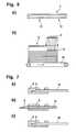
- FIG. 1Selective sterilization of a diagnostic test element with a lancing area protection.
- FIG. 2Selective sterilization of a diagnostic test element with a partially irradiated test
- FIG. 3Diagnostic test element with germ protection.
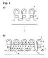
- FIG. 4Selective sterilization of connected diagnostic test elements.
- FIG. 5Selective sterilization of diagnostic test elements in a package.
- FIG. 6Basic procedure for the selective sterilization of a diagnostic test element.
- FIG. 7Lancing area protection made of pierceable material.
- FIG. 8Application of the selective sterilization to a lancing—measuring disposable with a so-called pooling area.
- FIG. 9Application of the selective sterilization to a diagnostic test element with a circular capillary gap.
- FIG. 10Application of the selective sterilization to a diagnostic test element with a flexible collecting foil.
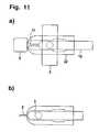
- FIG. 11Application of the selective sterilization to a diagnostic test element with a manually removable lancing area protection and a lancet that can be displaced relative to the test element base plate.
- FIG. 1shows schematically an embodiment of the method for selective sterilization.
- the figureshows a diagnostic test element ( 1 ) with a lancing area ( 2 ) and a detection area ( 3 ) where the test element ( 1 ) is sterilized by electron radiation ( 4 ).
- the screen ( 5 )screens the detection area ( 3 ) in such a manner that the detection area ( 3 ) is not sterilized in order to prevent the sterilization from damaging the detection chemistry and in particular the enzymes present in the detection area ( 3 ).
- the lancing area ( 2 )is sealed with a protection ( 6 ) which prevents entry of germs.
- the protection ( 6 )is permeable to the sterilizing electron radiation ( 4 ) and thus allows a sterilization of the lancing area ( 2 ) even when the protection ( 6 ) is in place and at the same time ensures that the lancing area ( 2 ) remains sterile after the sterilization until its intended use.
- FIG. 2shows another embodiment of the method according to the invention.
- the test zone ( 7 ) on which the detection chemistry is locatedis considerably larger than the detection area ( 3 ) which delineates the area in which the analyte is actually detected.
- the screen ( 5 )completely covers the detection area ( 3 ), but the test zone ( 7 ) is only partially screened.
- the lancing area ( 2 )is completely sealed by a protection ( 6 ) which prevents entry of germs. Accordingly during the subsequent sterilization with electron radiation ( 4 ) the detection chemistry which is located in the unprotected area of the test zone is also irradiated in addition to the lancing area ( 2 ). However, the resulting damage to the detection chemistry in this area is irrelevant to the detection of the analyte since only the reaction of the analyte with the detection chemistry in the detection area ( 3 ) is taken into account for the measurement.
- FIG. 3shows another embodiment of the method according to the invention.
- the detection area ( 3 )is provided with a protection against the escape of germs ( 8 ) and for this reason the lancing area ( 2 ) is not protected.
- the test element ( 1 )is placed in a primary packaging ( 9 ) for example similarly to FIGS. 5 b - d , the detection areas are screened and the lancing areas are irradiated.
- the test elementsare individually packaged within the primary packaging e.g. they are placed or individually sealed in individual chambers within the packaging such that when a test element is removed the sterility of the other test elements is ensured.
- FIG. 4shows another embodiment of the method according to the invention.
- a connected test elements ( 1 ) with a lancing area ( 2 ) and detection area ( 3 )are shown where the lancing area ( 2 ) is provided with a protection ( 6 ).
- FIG. 4 bshows the arrangement illustrated in FIG. 4 a during selective sterilization.
- the electron radiation ( 4 )irradiates the connected test elements ( 1 ) while the respective detection area ( 3 ) is protected from the irradiation ( 4 ) by a screen ( 5 ).
- FIG. 5shows another embodiment of the method according to the invention.
- FIG. 5 ashows a test element ( 1 ) with a lancing area ( 2 ), detection area ( 3 ) and protection of the lancing area ( 6 ) which is packaged in an oriented manner together with several test elements in a primary package ( 9 ) e.g. a container or a drum.
- a primary package9 e.g. a container or a drum.
- FIG. 5 awhich has a screen ( 5 ) that is designed such that in the subsequent irradiation with electron radiation ( 4 ) according to FIG. 5 d all detection areas ( 3 ) are protected from the radiation ( 4 ) and at the same time all lancing areas ( 2 ) are sterilized by the electron radiation ( 4 ).
- FIG. 6illustrates the principle of selective sterilization.
- FIG. 6 ashows a test element ( 1 ) which has a part to be protected ( 11 ) that should not be irradiated and a part to be irradiated ( 12 ) which should be sterilized by the electron radiation.
- FIG. 6 bshows an example illustrating the principle of the irradiation process in an electron beam arrangement.
- the radiation ( 4 )irradiates the part to be irradiated ( 12 ) of an arrangement of test elements ( 1 ) which are in an outer package ( 13 ) while the part to be protected ( 11 ) is screened by the screen ( 5 ).
- the test elementsare moved into the radiation area on a transport tape ( 14 ).
- the screen ( 5 )can be attached to the tape ( 14 ) or to the outer packaging ( 13 ).
- FIG. 8shows the application of the method according to the invention to a lancing—measurement disposable.
- the body fluidis collected in a so-called pooling area ( 16 ) during the lancing with the lancing area ( 2 ) and is transported via the capillary channel ( 17 ) and subchannels ( 18 ) into the detection area ( 3 ).
- the detection area ( 3 )is screened during the selective sterilization by an overlying screen ( 5 ).
- FIG. 9shows another possible application of the method according to the invention.
- the body fluidis transported in a circular capillary gap ( 17 ) from the lancing area ( 2 ) to the detection area ( 3 ) during the lancing.
- the detection area ( 3 )is screened by the screen ( 5 ) during the selective sterilization.
- FIG. 10shows another possible application of the method according to the invention.
- the integrated test elementhas a hydrophilic collecting foil ( 19 ) which hangs free over the lancing area and bends sideways during lancing and rests against the skin ( 20 ).
- the body fluid from the skin opening ( 21 )is transported along the collecting foil ( 19 ) into the capillary channel ( 17 ) and from there again into the detection area ( 3 ).
- the detection area ( 3 )is screened by the screen ( 5 ) during the selective sterilization.
- FIG. 11shows another possible application of the method according to the invention.
- the protective cap ( 6 )protects the lancing area ( 2 ) from contamination and is manually removed before use ( FIG. 11 a ).
- the lancet ( 15 ) with the lancing area ( 2 )is displaced during lancing relative to the test element base plate ( 22 ) ( FIG. 11 b ) and subsequently again retracts into the base plate during which body fluid passes through the capillary channel ( 17 ) into the detection area ( 3 ).
- the detection area ( 3 )is screened by the screen ( 5 ) during the selective sterilization in the production process.
Landscapes
- Health & Medical Sciences (AREA)
- Life Sciences & Earth Sciences (AREA)
- Engineering & Computer Science (AREA)
- Public Health (AREA)
- Animal Behavior & Ethology (AREA)
- Veterinary Medicine (AREA)
- General Health & Medical Sciences (AREA)
- Biomedical Technology (AREA)
- Biophysics (AREA)
- Heart & Thoracic Surgery (AREA)
- Medical Informatics (AREA)
- Molecular Biology (AREA)
- Surgery (AREA)
- Pathology (AREA)
- Physics & Mathematics (AREA)
- Hematology (AREA)
- Manufacturing & Machinery (AREA)
- Epidemiology (AREA)
- Dermatology (AREA)
- Measurement Of The Respiration, Hearing Ability, Form, And Blood Characteristics Of Living Organisms (AREA)
- Apparatus For Disinfection Or Sterilisation (AREA)
Abstract
Description
Claims (14)
Applications Claiming Priority (4)
| Application Number | Priority Date | Filing Date | Title |
|---|---|---|---|
| DE102004033219ADE102004033219A1 (en) | 2004-07-09 | 2004-07-09 | Method for the selective sterilization of diagnostic test elements |
| DE102004033219 | 2004-07-09 | ||
| DE102004033219.3 | 2004-07-09 | ||
| PCT/EP2005/007335WO2006005503A1 (en) | 2004-07-09 | 2005-07-07 | Method for the selective sterilisation of diagnostic test elements |
Related Parent Applications (1)
| Application Number | Title | Priority Date | Filing Date |
|---|---|---|---|
| PCT/EP2005/007335ContinuationWO2006005503A1 (en) | 2004-07-09 | 2005-07-07 | Method for the selective sterilisation of diagnostic test elements |
Publications (2)
| Publication Number | Publication Date |
|---|---|
| US20070176120A1 US20070176120A1 (en) | 2007-08-02 |
| US7794654B2true US7794654B2 (en) | 2010-09-14 |
Family
ID=34978653
Family Applications (1)
| Application Number | Title | Priority Date | Filing Date |
|---|---|---|---|
| US11/620,931Expired - Fee RelatedUS7794654B2 (en) | 2004-07-09 | 2007-01-08 | Method for the selective sterilization of diagnostic test elements |
Country Status (7)
| Country | Link |
|---|---|
| US (1) | US7794654B2 (en) |
| EP (1) | EP1781173B1 (en) |
| JP (1) | JP4722920B2 (en) |
| DE (1) | DE102004033219A1 (en) |
| ES (1) | ES2399238T3 (en) |
| PL (1) | PL1781173T3 (en) |
| WO (1) | WO2006005503A1 (en) |
Families Citing this family (64)
| Publication number | Priority date | Publication date | Assignee | Title |
|---|---|---|---|---|
| US6391005B1 (en) | 1998-03-30 | 2002-05-21 | Agilent Technologies, Inc. | Apparatus and method for penetration with shaft having a sensor for sensing penetration depth |
| US8641644B2 (en) | 2000-11-21 | 2014-02-04 | Sanofi-Aventis Deutschland Gmbh | Blood testing apparatus having a rotatable cartridge with multiple lancing elements and testing means |
| US9427532B2 (en) | 2001-06-12 | 2016-08-30 | Sanofi-Aventis Deutschland Gmbh | Tissue penetration device |
| US8337419B2 (en) | 2002-04-19 | 2012-12-25 | Sanofi-Aventis Deutschland Gmbh | Tissue penetration device |
| US9226699B2 (en) | 2002-04-19 | 2016-01-05 | Sanofi-Aventis Deutschland Gmbh | Body fluid sampling module with a continuous compression tissue interface surface |
| US7344507B2 (en) | 2002-04-19 | 2008-03-18 | Pelikan Technologies, Inc. | Method and apparatus for lancet actuation |
| US9795747B2 (en) | 2010-06-02 | 2017-10-24 | Sanofi-Aventis Deutschland Gmbh | Methods and apparatus for lancet actuation |
| US7041068B2 (en) | 2001-06-12 | 2006-05-09 | Pelikan Technologies, Inc. | Sampling module device and method |
| US7981056B2 (en) | 2002-04-19 | 2011-07-19 | Pelikan Technologies, Inc. | Methods and apparatus for lancet actuation |
| EP1395185B1 (en) | 2001-06-12 | 2010-10-27 | Pelikan Technologies Inc. | Electric lancet actuator |
| JP4209767B2 (en) | 2001-06-12 | 2009-01-14 | ペリカン テクノロジーズ インコーポレイテッド | Self-optimized cutting instrument with adaptive means for temporary changes in skin properties |
| US7749174B2 (en) | 2001-06-12 | 2010-07-06 | Pelikan Technologies, Inc. | Method and apparatus for lancet launching device intergrated onto a blood-sampling cartridge |
| US8267870B2 (en) | 2002-04-19 | 2012-09-18 | Sanofi-Aventis Deutschland Gmbh | Method and apparatus for body fluid sampling with hybrid actuation |
| US9248267B2 (en) | 2002-04-19 | 2016-02-02 | Sanofi-Aventis Deustchland Gmbh | Tissue penetration device |
| US7892183B2 (en) | 2002-04-19 | 2011-02-22 | Pelikan Technologies, Inc. | Method and apparatus for body fluid sampling and analyte sensing |
| US7547287B2 (en) | 2002-04-19 | 2009-06-16 | Pelikan Technologies, Inc. | Method and apparatus for penetrating tissue |
| US7901362B2 (en) | 2002-04-19 | 2011-03-08 | Pelikan Technologies, Inc. | Method and apparatus for penetrating tissue |
| US9795334B2 (en) | 2002-04-19 | 2017-10-24 | Sanofi-Aventis Deutschland Gmbh | Method and apparatus for penetrating tissue |
| US7674232B2 (en) | 2002-04-19 | 2010-03-09 | Pelikan Technologies, Inc. | Method and apparatus for penetrating tissue |
| US7229458B2 (en) | 2002-04-19 | 2007-06-12 | Pelikan Technologies, Inc. | Method and apparatus for penetrating tissue |
| US8360992B2 (en) | 2002-04-19 | 2013-01-29 | Sanofi-Aventis Deutschland Gmbh | Method and apparatus for penetrating tissue |
| US8221334B2 (en) | 2002-04-19 | 2012-07-17 | Sanofi-Aventis Deutschland Gmbh | Method and apparatus for penetrating tissue |
| US7491178B2 (en) | 2002-04-19 | 2009-02-17 | Pelikan Technologies, Inc. | Method and apparatus for penetrating tissue |
| US8372016B2 (en) | 2002-04-19 | 2013-02-12 | Sanofi-Aventis Deutschland Gmbh | Method and apparatus for body fluid sampling and analyte sensing |
| US9314194B2 (en) | 2002-04-19 | 2016-04-19 | Sanofi-Aventis Deutschland Gmbh | Tissue penetration device |
| US7331931B2 (en) | 2002-04-19 | 2008-02-19 | Pelikan Technologies, Inc. | Method and apparatus for penetrating tissue |
| US7708701B2 (en) | 2002-04-19 | 2010-05-04 | Pelikan Technologies, Inc. | Method and apparatus for a multi-use body fluid sampling device |
| US7909778B2 (en) | 2002-04-19 | 2011-03-22 | Pelikan Technologies, Inc. | Method and apparatus for penetrating tissue |
| US8702624B2 (en) | 2006-09-29 | 2014-04-22 | Sanofi-Aventis Deutschland Gmbh | Analyte measurement device with a single shot actuator |
| US8579831B2 (en) | 2002-04-19 | 2013-11-12 | Sanofi-Aventis Deutschland Gmbh | Method and apparatus for penetrating tissue |
| US8784335B2 (en) | 2002-04-19 | 2014-07-22 | Sanofi-Aventis Deutschland Gmbh | Body fluid sampling device with a capacitive sensor |
| US7976476B2 (en) | 2002-04-19 | 2011-07-12 | Pelikan Technologies, Inc. | Device and method for variable speed lancet |
| US7232451B2 (en) | 2002-04-19 | 2007-06-19 | Pelikan Technologies, Inc. | Method and apparatus for penetrating tissue |
| US7297122B2 (en) | 2002-04-19 | 2007-11-20 | Pelikan Technologies, Inc. | Method and apparatus for penetrating tissue |
| US8052926B2 (en)* | 2002-12-27 | 2011-11-08 | Roche Diagnostics Operations, Inc. | Method for manufacturing a sterilized lancet integrated biosensor |
| US7815579B2 (en) | 2005-03-02 | 2010-10-19 | Roche Diagnostics Operations, Inc. | Dynamic integrated lancing test strip with sterility cover |
| US7211052B2 (en) | 2002-12-30 | 2007-05-01 | Roche Diagnostics Operations, Inc. | Flexible test strip lancet device |
| US7214200B2 (en) | 2002-12-30 | 2007-05-08 | Roche Diagnostics Operations, Inc. | Integrated analytical test element |
| US8574895B2 (en) | 2002-12-30 | 2013-11-05 | Sanofi-Aventis Deutschland Gmbh | Method and apparatus using optical techniques to measure analyte levels |
| DE602004028463D1 (en) | 2003-05-30 | 2010-09-16 | Pelikan Technologies Inc | METHOD AND DEVICE FOR INJECTING LIQUID |
| US7850621B2 (en) | 2003-06-06 | 2010-12-14 | Pelikan Technologies, Inc. | Method and apparatus for body fluid sampling and analyte sensing |
| WO2006001797A1 (en) | 2004-06-14 | 2006-01-05 | Pelikan Technologies, Inc. | Low pain penetrating |
| US7920906B2 (en) | 2005-03-10 | 2011-04-05 | Dexcom, Inc. | System and methods for processing analyte sensor data for sensor calibration |
| US8282576B2 (en) | 2003-09-29 | 2012-10-09 | Sanofi-Aventis Deutschland Gmbh | Method and apparatus for an improved sample capture device |
| EP1680014A4 (en) | 2003-10-14 | 2009-01-21 | Pelikan Technologies Inc | METHOD AND DEVICE FOR A VARIABLE USER INTERFACE |
| US9247900B2 (en) | 2004-07-13 | 2016-02-02 | Dexcom, Inc. | Analyte sensor |
| US8668656B2 (en) | 2003-12-31 | 2014-03-11 | Sanofi-Aventis Deutschland Gmbh | Method and apparatus for improving fluidic flow and sample capture |
| US7822454B1 (en) | 2005-01-03 | 2010-10-26 | Pelikan Technologies, Inc. | Fluid sampling device with improved analyte detecting member configuration |
| WO2006011062A2 (en) | 2004-05-20 | 2006-02-02 | Albatros Technologies Gmbh & Co. Kg | Printable hydrogel for biosensors |
| US9775553B2 (en) | 2004-06-03 | 2017-10-03 | Sanofi-Aventis Deutschland Gmbh | Method and apparatus for a fluid sampling device |
| WO2005120365A1 (en) | 2004-06-03 | 2005-12-22 | Pelikan Technologies, Inc. | Method and apparatus for a fluid sampling device |
| US7654956B2 (en) | 2004-07-13 | 2010-02-02 | Dexcom, Inc. | Transcutaneous analyte sensor |
| US20070045902A1 (en) | 2004-07-13 | 2007-03-01 | Brauker James H | Analyte sensor |
| US7488298B2 (en) | 2004-10-08 | 2009-02-10 | Roche Diagnostics Operations, Inc. | Integrated lancing test strip with capillary transfer sheet |
| US8652831B2 (en) | 2004-12-30 | 2014-02-18 | Sanofi-Aventis Deutschland Gmbh | Method and apparatus for analyte measurement test time |
| GB0508255D0 (en) | 2005-04-25 | 2005-06-01 | Lucite Int Uk Ltd | Acrylic blends |
| EP2039607A1 (en)* | 2007-09-19 | 2009-03-25 | Roche Diagnostics GmbH | Joining foils with laser for sterile lancets |
| EP2265324B1 (en) | 2008-04-11 | 2015-01-28 | Sanofi-Aventis Deutschland GmbH | Integrated analyte measurement system |
| US9375169B2 (en) | 2009-01-30 | 2016-06-28 | Sanofi-Aventis Deutschland Gmbh | Cam drive for managing disposable penetrating member actions with a single motor and motor and control system |
| US8965476B2 (en) | 2010-04-16 | 2015-02-24 | Sanofi-Aventis Deutschland Gmbh | Tissue penetration device |
| DK2599505T3 (en) | 2011-11-30 | 2014-08-25 | Hoffmann La Roche | Method and sterilization device for sterilizing an implantable device |
| JP7071714B2 (en)* | 2019-02-08 | 2022-05-19 | Jfeエンジニアリング株式会社 | Electron beam sterilization method |
| JP7071713B2 (en)* | 2019-02-08 | 2022-05-19 | Jfeエンジニアリング株式会社 | Electron beam sterilization method |
| JP7071715B2 (en)* | 2019-02-08 | 2022-05-19 | Jfeエンジニアリング株式会社 | Electron beam sterilization method and electron beam sterilizer |
Citations (27)
| Publication number | Priority date | Publication date | Assignee | Title |
|---|---|---|---|---|
| US4442836A (en) | 1980-03-22 | 1984-04-17 | Clinicon Mannheim Gmbh | Blood lancet device |
| EP0199484A2 (en) | 1985-04-08 | 1986-10-29 | Audio Bionics Inc | Medical system |
| WO1990011095A2 (en) | 1989-03-10 | 1990-10-04 | Baxter International Inc. | Sterile product and method for sterilizing and assembling such product |
| US4981649A (en)* | 1988-03-25 | 1991-01-01 | Snow Brand Milk Products Co., Ltd. | Means for lid sterilization and temporal sealing |
| US5318584A (en) | 1992-04-13 | 1994-06-07 | Boehringer Mannheim Gmbh | Blood lancet device for withdrawing blood for diagnostic purposes |
| US5554166A (en) | 1993-06-21 | 1996-09-10 | Boehringer Mannheim Gmbh | Blood lancet device for withdrawing blood for diagnostic purposes |
| JPH09311205A (en)* | 1996-05-16 | 1997-12-02 | Gunze Ltd | Light diffusive sheet and its production |
| WO1998048695A1 (en) | 1997-04-29 | 1998-11-05 | Roche Diagnostics Gmbh | Single-use lancets |
| US6143164A (en) | 1997-02-06 | 2000-11-07 | E. Heller & Company | Small volume in vitro analyte sensor |
| US6191424B1 (en) | 1998-12-03 | 2001-02-20 | I-Ax Technologies | Irradiation apparatus for production line use |
| WO2001066010A1 (en) | 2000-03-04 | 2001-09-13 | Roche Diagnostics Gmbh | Blood lancet with hygienic tip protection |
| US6315738B1 (en) | 1999-01-04 | 2001-11-13 | Terumo Kabushiki Kaisha | Assembly having lancet and means for collecting and detecting body fluid |
| WO2002056751A2 (en) | 2001-01-22 | 2002-07-25 | Roche Diagnostics Gmbh | Lancet device having capillary action |
| US20020155267A1 (en)* | 2001-02-22 | 2002-10-24 | Bader Michael John | Multi-layer hermetically sealable film |
| DE10134650A1 (en) | 2001-07-20 | 2003-02-06 | Roche Diagnostics Gmbh | Small body fluid withdrawal system |
| US6520326B2 (en) | 1999-02-25 | 2003-02-18 | Medtronic Minimed, Inc. | Glucose sensor package system |
| EP1285629A1 (en) | 2001-01-19 | 2003-02-26 | Matsushita Electric Industrial Co., Ltd. | Lancet-integrated sensor, measurer for lancet-integrated sensor, and cartridge |
| US20030050573A1 (en)* | 2001-08-29 | 2003-03-13 | Hans-Juergen Kuhr | Analytical device with lancet and test element |
| US6572566B2 (en) | 2000-03-03 | 2003-06-03 | Roche Diagnostics Corporation | System for determining analyte concentrations in body fluids |
| US6594156B1 (en)* | 2000-04-24 | 2003-07-15 | Minimed Inc. | Device and method for circuit protection during radiation sterilization |
| WO2003089028A1 (en)* | 2002-04-22 | 2003-10-30 | Becton Dickinson France | Packaging for sterile objects or objects to be sterilized |
| EP1360931A1 (en) | 2002-05-09 | 2003-11-12 | Lifescan, Inc. | Physiological sample collection devices and method of using the same |
| US20030211619A1 (en)* | 2002-05-09 | 2003-11-13 | Lorin Olson | Continuous strip of fluid sampling and testing devices and methods of making, packaging and using the same |
| US6653096B1 (en)* | 1996-07-29 | 2003-11-25 | Process Challenge Devices | Process challenge device and method |
| EP1402812A1 (en) | 2002-09-30 | 2004-03-31 | Becton, Dickinson and Company | Integrated lancet and bodily fluid sensor |
| US20040106941A1 (en) | 2002-12-03 | 2004-06-03 | Roe Steven N. | Dual blade lancing test strip |
| US20070191736A1 (en)* | 2005-10-04 | 2007-08-16 | Don Alden | Method for loading penetrating members in a collection device |
Family Cites Families (1)
| Publication number | Priority date | Publication date | Assignee | Title |
|---|---|---|---|---|
| DE60012008T2 (en)* | 1999-05-21 | 2005-08-11 | Medtronic MiniMed, Inc., Northridge | PROCEDURE FOR PROTECTIVE SWITCHING DURING IRRADIATION STERILIZATION |
- 2004
- 2004-07-09DEDE102004033219Apatent/DE102004033219A1/ennot_activeCeased
- 2005
- 2005-07-07EPEP05764074Apatent/EP1781173B1/ennot_activeExpired - Lifetime
- 2005-07-07ESES05764074Tpatent/ES2399238T3/ennot_activeExpired - Lifetime
- 2005-07-07JPJP2007519720Apatent/JP4722920B2/ennot_activeExpired - Fee Related
- 2005-07-07WOPCT/EP2005/007335patent/WO2006005503A1/ennot_activeApplication Discontinuation
- 2005-07-07PLPL05764074Tpatent/PL1781173T3/enunknown
- 2007
- 2007-01-08USUS11/620,931patent/US7794654B2/ennot_activeExpired - Fee Related
Patent Citations (36)
| Publication number | Priority date | Publication date | Assignee | Title |
|---|---|---|---|---|
| US4442836A (en) | 1980-03-22 | 1984-04-17 | Clinicon Mannheim Gmbh | Blood lancet device |
| EP0199484A2 (en) | 1985-04-08 | 1986-10-29 | Audio Bionics Inc | Medical system |
| US4981649A (en)* | 1988-03-25 | 1991-01-01 | Snow Brand Milk Products Co., Ltd. | Means for lid sterilization and temporal sealing |
| US5496302A (en) | 1989-03-10 | 1996-03-05 | Baxter International Inc. | Method for sterilizing |
| WO1990011095A2 (en) | 1989-03-10 | 1990-10-04 | Baxter International Inc. | Sterile product and method for sterilizing and assembling such product |
| US5009654A (en) | 1989-03-10 | 1991-04-23 | Baxter International Inc. | Sterile product and method for sterilizing and assembling such product |
| US5009654B1 (en) | 1989-03-10 | 1993-07-13 | Baxter Int | |
| EP0425602B1 (en) | 1989-03-10 | 1995-09-06 | Baxter International Inc. | Sterile product and method for sterilizing and assembling such product |
| US5318584A (en) | 1992-04-13 | 1994-06-07 | Boehringer Mannheim Gmbh | Blood lancet device for withdrawing blood for diagnostic purposes |
| EP0565970B1 (en) | 1992-04-13 | 1997-09-24 | Boehringer Mannheim Gmbh | Blood lancet device for obtaining blood samples for diagnosis purpose |
| US5554166A (en) | 1993-06-21 | 1996-09-10 | Boehringer Mannheim Gmbh | Blood lancet device for withdrawing blood for diagnostic purposes |
| JPH09311205A (en)* | 1996-05-16 | 1997-12-02 | Gunze Ltd | Light diffusive sheet and its production |
| US6653096B1 (en)* | 1996-07-29 | 2003-11-25 | Process Challenge Devices | Process challenge device and method |
| US6143164A (en) | 1997-02-06 | 2000-11-07 | E. Heller & Company | Small volume in vitro analyte sensor |
| WO1998048695A1 (en) | 1997-04-29 | 1998-11-05 | Roche Diagnostics Gmbh | Single-use lancets |
| US6191424B1 (en) | 1998-12-03 | 2001-02-20 | I-Ax Technologies | Irradiation apparatus for production line use |
| US6315738B1 (en) | 1999-01-04 | 2001-11-13 | Terumo Kabushiki Kaisha | Assembly having lancet and means for collecting and detecting body fluid |
| US6520326B2 (en) | 1999-02-25 | 2003-02-18 | Medtronic Minimed, Inc. | Glucose sensor package system |
| US6572566B2 (en) | 2000-03-03 | 2003-06-03 | Roche Diagnostics Corporation | System for determining analyte concentrations in body fluids |
| WO2001066010A1 (en) | 2000-03-04 | 2001-09-13 | Roche Diagnostics Gmbh | Blood lancet with hygienic tip protection |
| US20030153939A1 (en) | 2000-03-04 | 2003-08-14 | Michael Fritz | Blood lancet with hygienic tip protection |
| US6880242B2 (en)* | 2000-04-24 | 2005-04-19 | Minimed Inc. | Method for circuit protection during radiation sterilization |
| US6594156B1 (en)* | 2000-04-24 | 2003-07-15 | Minimed Inc. | Device and method for circuit protection during radiation sterilization |
| EP1285629A1 (en) | 2001-01-19 | 2003-02-26 | Matsushita Electric Industrial Co., Ltd. | Lancet-integrated sensor, measurer for lancet-integrated sensor, and cartridge |
| WO2002056751A2 (en) | 2001-01-22 | 2002-07-25 | Roche Diagnostics Gmbh | Lancet device having capillary action |
| US20020155267A1 (en)* | 2001-02-22 | 2002-10-24 | Bader Michael John | Multi-layer hermetically sealable film |
| DE10134650A1 (en) | 2001-07-20 | 2003-02-06 | Roche Diagnostics Gmbh | Small body fluid withdrawal system |
| DE10142232A1 (en) | 2001-08-29 | 2003-03-20 | Roche Diagnostics Gmbh | Analytical tool with lancet and test element |
| US20030050573A1 (en)* | 2001-08-29 | 2003-03-13 | Hans-Juergen Kuhr | Analytical device with lancet and test element |
| WO2003089028A1 (en)* | 2002-04-22 | 2003-10-30 | Becton Dickinson France | Packaging for sterile objects or objects to be sterilized |
| EP1360931A1 (en) | 2002-05-09 | 2003-11-12 | Lifescan, Inc. | Physiological sample collection devices and method of using the same |
| US20030211619A1 (en)* | 2002-05-09 | 2003-11-13 | Lorin Olson | Continuous strip of fluid sampling and testing devices and methods of making, packaging and using the same |
| EP1402812A1 (en) | 2002-09-30 | 2004-03-31 | Becton, Dickinson and Company | Integrated lancet and bodily fluid sensor |
| US7192405B2 (en)* | 2002-09-30 | 2007-03-20 | Becton, Dickinson And Company | Integrated lancet and bodily fluid sensor |
| US20040106941A1 (en) | 2002-12-03 | 2004-06-03 | Roe Steven N. | Dual blade lancing test strip |
| US20070191736A1 (en)* | 2005-10-04 | 2007-08-16 | Don Alden | Method for loading penetrating members in a collection device |
Non-Patent Citations (1)
| Title |
|---|
| International Patent Application PCT/EP2005/007335 Search Report and Written Opinion Report mailed Oct. 12, 2005. |
Also Published As
| Publication number | Publication date |
|---|---|
| JP2008504918A (en) | 2008-02-21 |
| US20070176120A1 (en) | 2007-08-02 |
| DE102004033219A1 (en) | 2006-02-02 |
| ES2399238T3 (en) | 2013-03-26 |
| EP1781173B1 (en) | 2012-11-14 |
| PL1781173T3 (en) | 2013-04-30 |
| JP4722920B2 (en) | 2011-07-13 |
| EP1781173A1 (en) | 2007-05-09 |
| WO2006005503A1 (en) | 2006-01-19 |
Similar Documents
| Publication | Publication Date | Title |
|---|---|---|
| US7794654B2 (en) | Method for the selective sterilization of diagnostic test elements | |
| US7396334B2 (en) | Analytical device with lancet and test element | |
| US7771367B2 (en) | Lancet wheel | |
| JP5232003B2 (en) | Multi-part body fluid sampling and analysis cartridge | |
| JP4468324B2 (en) | Analysis aid | |
| JP4422551B2 (en) | Diagnostic test strip for collecting and detecting an analyte in a fluid sample and method of using the test strip | |
| US8506505B2 (en) | Portable measuring system having an optimized assembly space | |
| US20080243032A1 (en) | Analytical device including sterile protection | |
| CA2664747A1 (en) | Integrated sensor for analyzing biological samples | |
| CN101511269B (en) | Package for hydrophilic medical instruments | |
| RU2719948C2 (en) | Medical set for placing subsystem and medical device for introducing thereof into subject's body | |
| US8888715B2 (en) | Analysis system and method for determining an analyte in a body fluid with a magazine comprising integrated sample acquisition and analyzing elements | |
| US8172866B2 (en) | Medical aid | |
| US20100081968A1 (en) | Test Strip With Integrated Lancet | |
| JP2009545743A (en) | Packaging equipment for test equipment | |
| HK1165246A1 (en) | Lancet having capillary channel and sterile protection and method for producing such a lancet | |
| HK1165977A1 (en) | Test element magazine having covered test fields | |
| HK1165977B (en) | Test element magazine having covered test fields |
Legal Events
| Date | Code | Title | Description |
|---|---|---|---|
| AS | Assignment | Owner name:ROCHE DIAGNOSTICS OPERATIONS, INC., INDIANA Free format text:ASSIGNMENT OF ASSIGNORS INTEREST;ASSIGNOR:ROCHE DIAGNOSTICS GMBH;REEL/FRAME:018913/0235 Effective date:20070209 Owner name:ROCHE DIAGNOSTICS GMBH, GERMANY Free format text:ASSIGNMENT OF ASSIGNORS INTEREST;ASSIGNORS:SCHWIND, KARIN;FIEDLER, WOLFGANG;REEL/FRAME:018913/0232 Effective date:20070122 | |
| STCF | Information on status: patent grant | Free format text:PATENTED CASE | |
| CC | Certificate of correction | ||
| FPAY | Fee payment | Year of fee payment:4 | |
| AS | Assignment | Owner name:ROCHE DIABETES CARE, INC., INDIANA Free format text:ASSIGNMENT OF ASSIGNORS INTEREST;ASSIGNOR:ROCHE DIAGNOSTICS OPERATIONS, INC.;REEL/FRAME:036008/0670 Effective date:20150302 | |
| MAFP | Maintenance fee payment | Free format text:PAYMENT OF MAINTENANCE FEE, 8TH YEAR, LARGE ENTITY (ORIGINAL EVENT CODE: M1552) Year of fee payment:8 | |
| FEPP | Fee payment procedure | Free format text:MAINTENANCE FEE REMINDER MAILED (ORIGINAL EVENT CODE: REM.); ENTITY STATUS OF PATENT OWNER: LARGE ENTITY | |
| LAPS | Lapse for failure to pay maintenance fees | Free format text:PATENT EXPIRED FOR FAILURE TO PAY MAINTENANCE FEES (ORIGINAL EVENT CODE: EXP.); ENTITY STATUS OF PATENT OWNER: LARGE ENTITY | |
| STCH | Information on status: patent discontinuation | Free format text:PATENT EXPIRED DUE TO NONPAYMENT OF MAINTENANCE FEES UNDER 37 CFR 1.362 | |
| FP | Lapsed due to failure to pay maintenance fee | Effective date:20220914 |