US7794471B1 - Compliant anastomosis system - Google Patents
Compliant anastomosis systemDownload PDFInfo
- Publication number
- US7794471B1 US7794471B1US10/877,971US87797104AUS7794471B1US 7794471 B1US7794471 B1US 7794471B1US 87797104 AUS87797104 AUS 87797104AUS 7794471 B1US7794471 B1US 7794471B1
- Authority
- US
- United States
- Prior art keywords
- cutter
- connection module
- effector
- target vessel
- cutter assembly
- Prior art date
- Legal status (The legal status is an assumption and is not a legal conclusion. Google has not performed a legal analysis and makes no representation as to the accuracy of the status listed.)
- Active, expires
Links
- 230000003872anastomosisEffects0.000titleabstractdescription79
- 239000012636effectorSubstances0.000claimsabstractdescription123
- 239000012530fluidSubstances0.000claimsdescription18
- 238000005520cutting processMethods0.000claimsdescription5
- 210000001519tissueAnatomy0.000description50
- 230000007246mechanismEffects0.000description41
- 230000005540biological transmissionEffects0.000description33
- 238000000034methodMethods0.000description14
- 210000004351coronary vesselAnatomy0.000description10
- 230000023597hemostasisEffects0.000description8
- 239000008280bloodSubstances0.000description7
- 210000004369bloodAnatomy0.000description7
- 239000007789gasSubstances0.000description7
- 210000000709aortaAnatomy0.000description6
- 239000000463materialSubstances0.000description5
- 230000000149penetrating effectEffects0.000description5
- 230000004044responseEffects0.000description5
- IJGRMHOSHXDMSA-UHFFFAOYSA-NAtomic nitrogenChemical compoundN#NIJGRMHOSHXDMSA-UHFFFAOYSA-N0.000description4
- CURLTUGMZLYLDI-UHFFFAOYSA-NCarbon dioxideChemical compoundO=C=OCURLTUGMZLYLDI-UHFFFAOYSA-N0.000description4
- 238000013459approachMethods0.000description4
- 230000017531blood circulationEffects0.000description4
- 238000007373indentationMethods0.000description4
- 229910052751metalInorganic materials0.000description4
- 239000002184metalSubstances0.000description4
- 239000007787solidSubstances0.000description4
- 238000001356surgical procedureMethods0.000description4
- 238000013519translationMethods0.000description4
- 239000000853adhesiveSubstances0.000description3
- 230000001070adhesive effectEffects0.000description3
- 208000029078coronary artery diseaseDiseases0.000description3
- 238000003754machiningMethods0.000description3
- 238000000465mouldingMethods0.000description3
- 238000002360preparation methodMethods0.000description3
- 230000008569processEffects0.000description3
- 239000010935stainless steelSubstances0.000description3
- 229910001220stainless steelInorganic materials0.000description3
- XKRFYHLGVUSROY-UHFFFAOYSA-NArgonChemical compound[Ar]XKRFYHLGVUSROY-UHFFFAOYSA-N0.000description2
- 240000007643Phytolacca americanaSpecies0.000description2
- 230000009471actionEffects0.000description2
- 210000001367arteryAnatomy0.000description2
- 238000005452bendingMethods0.000description2
- 239000000560biocompatible materialSubstances0.000description2
- 210000004204blood vesselAnatomy0.000description2
- 239000001569carbon dioxideSubstances0.000description2
- 229910002092carbon dioxideInorganic materials0.000description2
- 238000010276constructionMethods0.000description2
- 238000004146energy storageMethods0.000description2
- 210000002216heartAnatomy0.000description2
- 230000003993interactionEffects0.000description2
- 210000004165myocardiumAnatomy0.000description2
- 229910052757nitrogenInorganic materials0.000description2
- 230000035515penetrationEffects0.000description2
- 239000007779soft materialSubstances0.000description2
- 238000012360testing methodMethods0.000description2
- 230000007704transitionEffects0.000description2
- 238000003466weldingMethods0.000description2
- 108010080379Fibrin Tissue AdhesiveProteins0.000description1
- 208000031481Pathologic ConstrictionDiseases0.000description1
- 239000003570airSubstances0.000description1
- 239000012080ambient airSubstances0.000description1
- 210000003484anatomyAnatomy0.000description1
- 229910052786argonInorganic materials0.000description1
- 238000010009beatingMethods0.000description1
- 230000015572biosynthetic processEffects0.000description1
- 230000002308calcificationEffects0.000description1
- 230000008859changeEffects0.000description1
- 239000011248coating agentSubstances0.000description1
- 238000000576coating methodMethods0.000description1
- 238000012790confirmationMethods0.000description1
- 230000000881depressing effectEffects0.000description1
- 238000013461designMethods0.000description1
- 230000000694effectsEffects0.000description1
- 238000002474experimental methodMethods0.000description1
- 210000001349mammary arteryAnatomy0.000description1
- 238000004519manufacturing processMethods0.000description1
- 238000002324minimally invasive surgeryMethods0.000description1
- 238000012986modificationMethods0.000description1
- 230000004048modificationEffects0.000description1
- 229910001000nickel titaniumInorganic materials0.000description1
- OCDRLZFZBHZTKQ-NMUBGGKPSA-NonetineChemical compoundC[C@@H](O)[C@@]1(O)C[C@@H](C)[C@@](C)(O)C(=O)OC\C2=C\CN(C)CC[C@@H](OC1=O)C2=OOCDRLZFZBHZTKQ-NMUBGGKPSA-N0.000description1
- 210000000056organAnatomy0.000description1
- 230000037361pathwayEffects0.000description1
- 230000002093peripheral effectEffects0.000description1
- 229920000515polycarbonatePolymers0.000description1
- 239000004417polycarbonateSubstances0.000description1
- 229920006267polyester filmPolymers0.000description1
- 229920001296polysiloxanePolymers0.000description1
- 238000003825pressingMethods0.000description1
- 238000000926separation methodMethods0.000description1
- 238000005476solderingMethods0.000description1
- 230000006641stabilisationEffects0.000description1
- 238000011105stabilizationMethods0.000description1
- 208000037804stenosisDiseases0.000description1
- 230000036262stenosisEffects0.000description1
- 239000000126substanceSubstances0.000description1
- 239000000758substrateSubstances0.000description1
- 230000001225therapeutic effectEffects0.000description1
- 230000002792vascularEffects0.000description1
- 238000007631vascular surgeryMethods0.000description1
- 210000003462veinAnatomy0.000description1
- 230000000007visual effectEffects0.000description1
Images


Classifications
- A—HUMAN NECESSITIES
- A61—MEDICAL OR VETERINARY SCIENCE; HYGIENE
- A61B—DIAGNOSIS; SURGERY; IDENTIFICATION
- A61B17/00—Surgical instruments, devices or methods
- A61B17/11—Surgical instruments, devices or methods for performing anastomosis; Buttons for anastomosis
- A—HUMAN NECESSITIES
- A61—MEDICAL OR VETERINARY SCIENCE; HYGIENE
- A61B—DIAGNOSIS; SURGERY; IDENTIFICATION
- A61B17/00—Surgical instruments, devices or methods
- A61B17/04—Surgical instruments, devices or methods for suturing wounds; Holders or packages for needles or suture materials
- A61B17/0491—Sewing machines for surgery
- A—HUMAN NECESSITIES
- A61—MEDICAL OR VETERINARY SCIENCE; HYGIENE
- A61B—DIAGNOSIS; SURGERY; IDENTIFICATION
- A61B17/00—Surgical instruments, devices or methods
- A61B17/11—Surgical instruments, devices or methods for performing anastomosis; Buttons for anastomosis
- A61B17/115—Staplers for performing anastomosis, e.g. in a single operation
- A61B17/1152—Staplers for performing anastomosis, e.g. in a single operation applying the staples on the outside of the lumen
- A—HUMAN NECESSITIES
- A61—MEDICAL OR VETERINARY SCIENCE; HYGIENE
- A61B—DIAGNOSIS; SURGERY; IDENTIFICATION
- A61B17/00—Surgical instruments, devices or methods
- A61B17/12—Surgical instruments, devices or methods for ligaturing or otherwise compressing tubular parts of the body, e.g. blood vessels or umbilical cord
- A61B17/128—Surgical instruments, devices or methods for ligaturing or otherwise compressing tubular parts of the body, e.g. blood vessels or umbilical cord for applying or removing clamps or clips
- A61B17/1285—Surgical instruments, devices or methods for ligaturing or otherwise compressing tubular parts of the body, e.g. blood vessels or umbilical cord for applying or removing clamps or clips for minimally invasive surgery
- A—HUMAN NECESSITIES
- A61—MEDICAL OR VETERINARY SCIENCE; HYGIENE
- A61B—DIAGNOSIS; SURGERY; IDENTIFICATION
- A61B17/00—Surgical instruments, devices or methods
- A61B17/32—Surgical cutting instruments
- A61B17/3205—Excision instruments
- A61B17/32053—Punch like cutting instruments, e.g. using a cylindrical or oval knife
- A—HUMAN NECESSITIES
- A61—MEDICAL OR VETERINARY SCIENCE; HYGIENE
- A61B—DIAGNOSIS; SURGERY; IDENTIFICATION
- A61B17/00—Surgical instruments, devices or methods
- A61B17/32—Surgical cutting instruments
- A61B17/3205—Excision instruments
- A61B17/3207—Atherectomy devices working by cutting or abrading; Similar devices specially adapted for non-vascular obstructions
- A61B17/320758—Atherectomy devices working by cutting or abrading; Similar devices specially adapted for non-vascular obstructions with a rotating cutting instrument, e.g. motor driven
- A—HUMAN NECESSITIES
- A61—MEDICAL OR VETERINARY SCIENCE; HYGIENE
- A61B—DIAGNOSIS; SURGERY; IDENTIFICATION
- A61B17/00—Surgical instruments, devices or methods
- A61B17/11—Surgical instruments, devices or methods for performing anastomosis; Buttons for anastomosis
- A61B17/115—Staplers for performing anastomosis, e.g. in a single operation
- A61B17/1155—Circular staplers comprising a plurality of staples
- A—HUMAN NECESSITIES
- A61—MEDICAL OR VETERINARY SCIENCE; HYGIENE
- A61B—DIAGNOSIS; SURGERY; IDENTIFICATION
- A61B17/00—Surgical instruments, devices or methods
- A61B17/00234—Surgical instruments, devices or methods for minimally invasive surgery
- A61B2017/00349—Needle-like instruments having hook or barb-like gripping means, e.g. for grasping suture or tissue
- A—HUMAN NECESSITIES
- A61—MEDICAL OR VETERINARY SCIENCE; HYGIENE
- A61B—DIAGNOSIS; SURGERY; IDENTIFICATION
- A61B17/00—Surgical instruments, devices or methods
- A61B2017/00681—Aspects not otherwise provided for
- A61B2017/00685—Archimedes screw
- A—HUMAN NECESSITIES
- A61—MEDICAL OR VETERINARY SCIENCE; HYGIENE
- A61B—DIAGNOSIS; SURGERY; IDENTIFICATION
- A61B17/00—Surgical instruments, devices or methods
- A61B17/11—Surgical instruments, devices or methods for performing anastomosis; Buttons for anastomosis
- A61B2017/1103—Approximator
- A—HUMAN NECESSITIES
- A61—MEDICAL OR VETERINARY SCIENCE; HYGIENE
- A61B—DIAGNOSIS; SURGERY; IDENTIFICATION
- A61B17/00—Surgical instruments, devices or methods
- A61B17/11—Surgical instruments, devices or methods for performing anastomosis; Buttons for anastomosis
- A61B2017/1107—Surgical instruments, devices or methods for performing anastomosis; Buttons for anastomosis for blood vessels
- A—HUMAN NECESSITIES
- A61—MEDICAL OR VETERINARY SCIENCE; HYGIENE
- A61B—DIAGNOSIS; SURGERY; IDENTIFICATION
- A61B17/00—Surgical instruments, devices or methods
- A61B17/11—Surgical instruments, devices or methods for performing anastomosis; Buttons for anastomosis
- A61B2017/1132—End-to-end connections
- A—HUMAN NECESSITIES
- A61—MEDICAL OR VETERINARY SCIENCE; HYGIENE
- A61B—DIAGNOSIS; SURGERY; IDENTIFICATION
- A61B17/00—Surgical instruments, devices or methods
- A61B17/11—Surgical instruments, devices or methods for performing anastomosis; Buttons for anastomosis
- A61B2017/1135—End-to-side connections, e.g. T- or Y-connections
- A—HUMAN NECESSITIES
- A61—MEDICAL OR VETERINARY SCIENCE; HYGIENE
- A61B—DIAGNOSIS; SURGERY; IDENTIFICATION
- A61B90/00—Instruments, implements or accessories specially adapted for surgery or diagnosis and not covered by any of the groups A61B1/00 - A61B50/00, e.g. for luxation treatment or for protecting wound edges
- A61B90/06—Measuring instruments not otherwise provided for
- A61B2090/061—Measuring instruments not otherwise provided for for measuring dimensions, e.g. length
Definitions
- the present inventionrelates generally to anastomosis, and more particularly to a system for performing a compliant anastomosis.
- Anastomosisis a procedure where two separate tubular or hollow organs are surgically grafted together to form a continuous fluid channel between them.
- Vascular anastomosisinvolves creating an anastomosis between blood vessels to create or restore blood flow.
- CADcoronary artery disease
- an occlusion or stenosis in a coronary arteryrestricts blood flow to the heart muscle.
- the area where the occlusion occursis bypassed to reroute blood flow by grafting a vessel in the form of a harvested artery or vein, or a prosthesis.
- Anastomosisis performed between a graft vessel and two target vessels in order to bypass the blocked coronary artery, circumvent the occlusion and restore adequate blood flow to the heart muscle.
- This treatmentis known as a coronary artery bypass graft procedure (CABG).
- CABGcoronary artery bypass graft procedure
- An anastomosismay be compliant or noncompliant.
- a noncompliant anastomosisis one in which the anastomosis opening in the target vessel is not substantially free to expand or contract radially.
- a noncompliant anastomosismay be formed with a one-piece or multiple-piece anastomosis device that compresses or otherwise controls tissue in the vicinity of the anastomosis to hold the graft vessel in place relative to the target vessel.
- Noncompliant anastomoseshave been successful, such as when utilizing anastomosis devices deployed by Cardica's PAS-PortTM anastomosis system.
- a compliant anastomosisis one in which the target vessel is substantially free to expand or contract circumferentially and longitudinally in proximity to the anastomosis site.
- a traditional sutured anastomosisis compliant, and for this reason some surgeons would prefer to utilize an anastomosis system that provides a compliant anastomosis, particularly between a graft vessel and the aorta or other source of arterial blood.
- an integrated anastomosis toolincludes an effector that both creates an opening in the wall of a target vessel and deploys a plurality of independent connectors to connect a graft vessel to the target vessel to form a compliant anastomosis.
- the effectorincludes a cutter assembly for creating the opening and a connection module for deploying the connectors.
- the connectorsmay be staples, clips or any other suitable structures or mechanisms.
- the effectoris connected to an actuator directly or indirectly.
- the actuatortransmits energy to the effector to actuate the cutter assembly and the connection module.
- the actuatormay store energy for transmission to the effector in any suitable form and in any suitable structure and/or mechanism.
- the actuatormay be connected to an external source of energy, such as compressed gas or electric power, without substantially storing energy within itself.
- the particular energy source used and/or the structure or mechanism for energy storagemay be independent from the configuration of the effector.
- the actuatormay be part of or connected to a handle graspable by a user.
- the effectoris connected to the actuator via an interface member.
- the interface membermay be hinged, flexible, articulated or otherwise configured to allow the effector to be positioned at two or more different positions relative to the actuator.
- the effectorcan be oriented to facilitate the connection of the graft vessel to that target vessel, without the need to hold the actuator in an awkward position. Further, in this way the use of the effector in minimally-invasive surgery through a small incision in the patient is facilitated.
- the cutter assembly and the connection moduleeach may be attached to or otherwise associated with at least one transmission member such as a cable.
- at least one transmission membermay be a flexible shaft, a gear or gear assembly, a belt, or any other suitable mechanism.
- Each transmission memberis in turn connected to the actuator.
- the cutter assemblymay be actuated by motion of at least one transmission member connected to or otherwise associated with it, and the connection module may be actuated by motion of at least one transmission member connected to or otherwise associated with it.
- a transmission membermay be attached to and cause motion of a traveler, which in turn causes motion of the connection module.
- the transmission member or members connected to the cutter assemblymay be independent from the transmission member or members connected to the connection module, to allow the cutter assembly to be actuated independently from the connection module.
- the cutter assembly and the connection modulemay be actuated sequentially by sequentially moving different transmission members.
- the cutter assemblyincludes a cutter member that includes a cutter, and a holder that receives at least a portion of the cutter.
- the cuttermay be at least partially cylindrical, and the holder may include a corresponding tubular bore therethrough.
- the distal end of the cutteris a cutting edge that is sharpened as by beveling, and may be circular or otherwise shaped. Further, the distal end of the cutter is tubular or otherwise substantially hollow in order to receive tissue cut from the wall of the target vessel.
- An augerextends from the distal end of the cutter, such as along the longitudinal axis of the tube. The auger may be threaded or fluted, or may be unthreaded and configured like a spike or spear.
- the augermay be fixed translationally and/or rotationally relative to the cutter.
- a transmission memberis connected to the cutter member, and may extend through a lateral passage in the holder. Motion of at least one transmission member associated with the cutter assembly may both rotate and advance the cutter.
- a portion of the outer surface of the cutter memberis threaded, and the transmission member is a cable wound along the threads, such that motion of the cable rotates and advances the cutter.
- the effectorincludes at least one registration element that is configured to maintain the effector in substantially the same location relative to the target vessel throughout actuation of the effector.
- a number of registration elementsextend distally from the effector and are configured to engage the tissue of the target vessel.
- at least one registration elementis configured to test the thickness and/or tissue quality of the wall of the target vessel.
- Each registration elementhas a cross-section area small enough that its separation from the target vessel causes at most minimal leakage through the wall of the target vessel.
- one or more thickness sensorsmay be provided independent from the registration element or elements.
- a graft vesselis loaded onto the connection module.
- the connection moduleis moved to the closed position if it is not already in the closed position, and a graft vessel is pulled through a passage in the connection module such as by a pull-through tool or tools.
- the connection moduleallows side loading and release of the graft vessel to provide greater surgical flexibility.
- An end of the graft vesselis everted over at least a part of each connector.
- connection moduleis loaded into the effector if it is not already in the effector.
- the distal end of the effectormay be placed on the target vessel at a potential anastomosis site.
- the effectormay include a port or other opening therein to allow the operator to better visualize the intended anastomosis site.
- At least one registration elementengages the target vessel as the effector is placed against it.
- At least one registration elementis configured to measure the thickness of the wall of the target vessel.
- fluidenters the hollow interior of the registration element through its distal end and exits through the aperture, providing visual confirmation that the tissue of the wall of the target vessel is of suitable thickness and is not calcified.
- the wall of the target vesselis too thick, or is calcified, no fluid exits the aperture because the end of the registration element has not penetrated the wall of the target vessel completely, and the potential anastomosis site is not suitable.
- the operatorthen removes the effector from the target vessel and places it at a different potential anastomosis site on the target vessel. In this way, an operator can easily determine whether the selected anastomosis site on the target vessel is appropriate.
- the cutter assemblyis actuated by the corresponding transmission member to create an opening in the wall of the target vessel.
- the transmission memberis a cable wound about at least a portion of the cutter member
- the proximal motion of the cablecauses the cutter to advance as well as rotate about its longitudinal axis.
- the bore in the holderguides and stabilizes the cutter as it advances. As the cutter advances and spins, it enters the tissue of the target vessel through the aperture in the stop at the distal end of the effector, and creates an opening therein.
- the augermay be fixed longitudinally relative to the cutter, such that it advances longitudinally at the same rate as the cutter.
- the cutterin another aspect of the invention, after the cutter creates an opening in the wall of the target vessel, it is moved out of the way of the connection module.
- the transmission member attached to the cutteris a cable
- the cutter assemblymoves proximally, out of and then away from the opening in the target vessel.
- the cutter assemblythen moves in a direction that has a component substantially perpendicular to the direction of its previous longitudinal motion.
- the cutter assemblymoves in a different direction relative to the direction of its previous longitudinal motion, such as by rotating on an axis away from that direction.
- the cutter assembly and the connection moduleinitially may be arranged substantially along an axis, where the cutter assembly is movable away from that axis before the connection module is shuttled distally. In this way, the cutter assembly is moved out of the way of the connection module.
- connection moduleis actuated by a corresponding transmission member, and translates distally toward the opening. Distal motion of the connection module may cease when it contacts a stop. At that time, where the connectors are staples, a tine of each staple may extend through the opening in the wall of the target vessel created by the cutter assembly, and another tine of each staple may penetrate completely through the wall of the target vessel.
- the connection modulemay include at least one plate that has a number of apertures defined in it and an anvil extending into each aperture. A staple is positioned adjacent to each anvil, and may be held in place by that anvil. Each plate may rotate, such as about the longitudinal centerline of the connection member.
- One or more driversare located proximal to the staples, and are movable distally to push each staple distally against the corresponding anvil.
- connection modulequickly shuttles distally and deploys the connectors after the cutter assembly has been moved out of the way.
- the connection moduleshuttles distally and deploys the connectors in one second or less. Because of the short duration between creation of the opening in the wall of the target vessel and completion of the anastomosis, hemostasis need not be maintained, as only a small amount of fluid escapes through the opening in the target vessel. In this way, construction of the effector is simplified.
- connection modulesubstantially stops its distal motion
- forceis still exerted on the connection module in the distal direction.
- This forcepushes on the driver or drivers, which in turn exert a force on the connectors in a distal direction that deploys them, anastomosing the graft vessel to the target vessel.
- the motion of the driver or driversexerts a force against each connector, which deforms upon contact with the corresponding anvil.
- the connectorsare self-deforming, and the force exerted by the driver or drivers is applied to the connection module in a manner that releases the connectors for self-deformation.
- the anastomosisis complete. Each plate is rotated or otherwise moved to clear the anvils out of the way and release the connectors from the connection module through the apertures in the plate.
- one tine of each staplemay extend through and bends substantially radially outward from the opening in the wall of the target vessel, thereby contacting the inner surface of the wall of the target vessel without penetrating it in response to the force exerted by the driver or drivers. That tine penetrates the wall of the graft vessel, either as part of the prior preparation of the graft, or in response to the force exerted by the driver or drivers. Further, in response to that force another tine of each staple may penetrate, partially or completely, the wall of the target vessel from the outside. Optionally, that tine may penetrate the wall of the graft vessel.
- connection modulemoves to the open position, releasing the graft vessel.
- the connection modulemay be biased to the open position, and distal force exerted against the connection module may release a catch that previously had overcome that bias to hold the connection module closed. The effector is then removed from the target vessel.
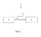
- FIG. 1is a schematic view of an integrated anastomosis tool having an actuator and an effector.
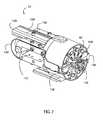
- FIG. 2is a perspective view of an exemplary effector.
- FIG. 3is a perspective view of an exemplary cutter assembly of an effector.
- FIG. 3Ais a perspective view of an exemplary holder that may be used in the cutter assembly.
- FIG. 4is a cross-section view of a cutter member of the cutter assembly.
- FIG. 5is a cross-section view of the cutter member showing a cutter cable wrapped around a portion thereof.
- FIG. 6is a perspective view of one example of a connection module of an effector of an integrated anastomosis tool, where the connection module is in an open position.
- FIG. 7is a perspective view of the connection module of FIG. 6 in a closed position.
- FIG. 8is a front view of an exemplary connector that may be used in conjunction with the connection module.
- FIG. 9is a top view of an anvil plate that may be used in conjunction with the connection module, showing the relationship between the anvil plate and connectors.
- FIG. 10is a top cross-section view of a traveler.
- FIG. 11is a side cutaway view of the effector in an initial configuration.
- FIG. 11Ais a perspective view of an exemplary poke-through tool.
- FIG. 11Bis a perspective view of an end-to-side anastomosis having a cobrahead configuration.
- FIG. 12is a side cutaway view of the effector in a second configuration after the cutter member of the cutter assembly has moved distally.
- FIG. 13is a side cutaway view of the effector in a third configuration after the cutter assembly has moved proximally after creating an opening in the target vessel.
- FIG. 14is a side cutaway view of the effector in a fourth configuration after the cutter assembly has moved off-axis.
- FIG. 15is a side cutaway view of the effector in a fifth configuration after the connection module has shuttled distally.
- FIG. 16is a side cross-section view of tines of connectors entering the opening in the target vessel with the graft vessel everted over those tines, as the connection module moves distally to the position of FIG. 15 .
- FIG. 17is a side cross-section view of a connector positioned in the target vessel after the connection module has moved to the position of FIG. 15 , prior to deployment.
- FIG. 18is a side cross-section view of a connector positioned in the target vessel after the connection module has moved to the position of FIG. 15 , after deployment.
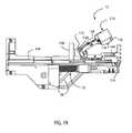
- FIG. 19is a side cutaway view of the effector in a sixth configuration after the connection module has deployed connectors to connect the graft vessel to the target vessel and has opened to release the graft vessel.
- This specificationdescribes an exemplary embodiment of an integrated anastomosis tool and an exemplary method for using that tool.
- an integrated anastomosis tool 2includes an effector 4 connected to an actuator 6 , such as by an interface member 8 .
- the interface member 8may be flexible, articulated, hinged or otherwise configured in any suitable manner to allow the effector 4 to be positioned at two or more different positions relative to the actuator 6 . That is, the interface member 8 may be bent, manipulated or otherwise moved such that the effector 4 may be positioned in more than one orientation relative to the actuator 6 . Articulation or other motion of the interface member 8 may be located anywhere along the length of the interface member 8 , or on the effector 4 or actuator 6 . Alternately, control of the articulation may be integrated into the actuation sequence of the tool 2 .
- the effector 4can be oriented by the user to facilitate the connection of a graft vessel to a target vessel without the need to hold the actuator 6 in an awkward position.
- the interface member 8may be rigid.
- the effector 4may be connected directly to the actuator 6 .
- the effector 4 and actuator 6may be fixed mechanically relative to one another, such as by securing both the effector 4 and actuator 6 to a common frame or housing.
- the actuator 6may be connected operationally to the effector 4 by one or more transmission members (not shown). At least one transmission member may be a cable, a rod, a belt, a chain, a tube or other structure for transmitting fluid or hydraulic pressure, one or more electrical wires and/or motors, or any other suitable structure or mechanism. Where more than one transmission member is utilized, one or more of the transmission members may be configured differently from one or more of the others. For example, the transmission members may include a cable used in conjunction with a rod.
- the actuator 6is operationally connected to the effector 4 by one or more transmission members, and as a result the mechanical configuration of the actuator 6 is independent of the mechanical configuration of the effector 4 .
- the actuator 6may be any mechanism capable of actuating the transmission members in such a way as to operate the effector 4 .
- the effector 4presents a standard interface to the actuator 6 , such that any actuator 6 that meets the standard interface may be utilized.
- the design of a particular configuration of the actuator 6 to achieve desired motion of one or more transmission membersis within the capability of one skilled in the art.
- the actuator 6is directly connected to the effector 4 , and transmission members are not used, such that the mechanical configurations of the actuator 6 and of the effector 4 are not independent.
- the actuator 6transmits energy to the effector 4 to actuate it, such as via the one or more transmission members.
- the actuator 6may store energy for transmission to the effector 4 .
- Such energymay be stored in any suitable form, and in any suitable structure and/or mechanism.
- a reservoir of compressed gassuch as carbon dioxide, argon or nitrogen is included within or connected to the actuator 6 , in which energy is stored in the form of gas pressure.
- a battery or batteriesare included within or connected to the actuator 6 , such that electrical energy is stored.
- a spring or springsare included within or connected to the actuator 6 and deformed, such that energy is stored as a result of the deformation of that spring or springs.
- the actuator 6may be connectable to an external source of energy used to transmit force to the effector 4 , instead of or in conjunction with an internal energy source within the actuator 6 .
- the actuator 6may be connectable to an external electrical outlet that provides AC or DC power.
- the actuator 6may be connectable to an external source of compressed gas, such as carbon dioxide or nitrogen.
- the actuator 6may be connectable to an external vacuum source. Such vacuum may be utilized, for example, to draw ambient air into and/or through the actuator 6 to drive an impeller, thereby generating energy for transmission to the effector 4 .
- energymay be received from an external source by the actuator 6 .
- the particular energy source utilized and/or the structure or mechanism for energy storageis independent from the configuration of the effector 4 . Alternately, energy is stored in the effector 4 , or received from a source other than the actuator 6 by the effector 4 , and the actuator 6 controls the application of such energy without substantially storing or transmitting it.
- the actuator 6may form, be part of or be connected to a handle (not shown) of the integrated anastomosis tool 2 that is graspable by a user.
- the effector 4may form, be part of or be connected to a handle (not shown) of the integrated anastomosis tool 2 that is graspable by a user.
- the use of two handlesmay be advantageous where the interface member or members 8 are substantially flexible.
- At least one handlemay be configured to facilitate its handling by a robotic end effector or other mechanism.
- the effector 4includes a frame 14 , and a cutter assembly 10 and a connection module 12 that are both movable relative to the frame 14 .
- at least one of the cutter assembly 10 and the cutter deployment array 12is substantially fixed relative to at least part of the frame 14 , where that part of the frame 14 may or may not be movable relative to a remainder of the frame 14 .
- the cutter assembly 10creates an opening in the wall of a target vessel, and the connection module 12 connects a graft vessel to the target vessel, such as by deploying one or more connectors 90 .
- the effector 4includes a cutter assembly 10 .
- the cutter assembly 10includes a cutter member 18 , and a holder 20 with a bore 22 defined therein that receives at least a portion of the cutter member 18 .
- the bore 22may extend partly into or completely through the holder 20 .
- the cutter member 18includes a cutter transport 28 connected to a cutter 24 , where the cutter 20 is distal to the cutter transport 28 .
- the cutter 24may be fixed to an auger 30 , either of which may be configured as described in U.S. patent application Ser. No. 10/054,745 or U.S. patent application Ser. No. 10/659,057, both of which are incorporated by reference herein in their entirety.
- the cutter 24is constructed from a metal, such as stainless steel, but a different material may be used if desired.
- the cutter 24may be constructed from biocompatible material, if desired.
- the cutter 24is a hollow tubular structure with an open distal end.
- the distal end of the cutter 24has a substantially circular shape, and the cutter 24 has a substantially circular cross-section along its length.
- at least part of the cutter 24may take another shape, have a different cross section, or vary in cross sectional perimeter or area along its length.
- the cutter 24may take the shape of a tube having an open slit along its length. That is, the cutter 24 may form the majority of a cylindrical surface, where the cutter 24 extends along, for example, 350° of the complete 360° perimeter of the cylinder.
- the distal end of the cutter 24may be angled relative to its longitudinal axis, if desired. That is, the distal end of the cutter 24 may be coincident with a plane angled relative to the longitudinal axis of the cutter 24 .
- the proximal end of the cutter 24has a larger diameter than the cutter transport 28 , such that a shoulder 43 results from that difference in diameter.
- the shoulder 43may be circumferential. Alternately, the shoulder 43 may include one or more separate segments. Alternately, the cutter 24 has the same diameter or a smaller diameter than the cutter transport 28 , and the shoulder 43 is at least one stub or other structure that extends outward further than the outer surface of the cutter transport 28 adjacent to the cutter 24 .
- the distal end of the cutter 24is sharpened to cut the wall of a tubular vessel, such as the aorta or other blood vessel.
- the distal end of the cutter 24may be beveled for sharpness.
- the distal end of the cutter 24may be beveled inward, such that an inner surface 32 of the cutter 24 contacts a vessel wall before an outer surface 34 of the cutter 24 , or beveled outward, such that the inner surface 32 contacts a vessel wall after the outer surface 34 .
- the distal end of the cutter 24may be beveled both inward and outward, such that a sharp edge is provided at a location between the inner surface 32 and outer surface 34 of the cutter 24 .
- less than the entire circumference of the distal end of the cutter 24is sharpened.
- the distal end of the cutter 24is at least partially serrated.
- the inner surface 32may be substantially smooth. Alternately, at least a portion of the inner surface 32 may be rough to facilitate capture of tissue removed from the wall of a target vessel by increasing the coefficient of friction between the inner surface 32 and captured tissue. Alternately, the inner surface 32 may include one or more tissue plug capture features (not shown) defined therein to facilitate capture of tissue removed from the wall of a target vessel.
- the outer surface 34 of the cutter 24may be substantially smooth as well.
- the cutter 24is connected to an auger 30 , which may be constructed from the same biocompatible metal as the cutter 24 or from a different biocompatible material.
- the auger 30may be substantially coaxial with the cutter 24 .
- the auger 30may be connected to the cutter 24 indirectly via the cutter transport 28 . That is, the auger 30 may be connected to or formed integrally with the cutter transport 28 , which in turn is connected to the cutter 24 .
- the auger 30is fixed relative to the cutter 24 , such that the auger 30 and cutter 24 both translate and rotate together at the same rates. Alternately, the auger 30 is translationally fixed relative to the cutter 24 such that the auger 30 and cutter 24 translate at the same rate, but is at least partially free to rotate relative to the cutter 24 .
- the auger 30may include a circumferential flange (not shown) held within a corresponding groove (not shown) in the cutter 24 .
- the flangecan rotate within the groove, and contact between the flange and the groove causes the auger 30 and cutter 24 to translate together.
- the auger 30 and the cutter 24are fixed axially, but independent rotationally.
- Other mechanisms or structuresmay be used to allow the auger 30 and the cutter 24 to translate together axially while having the capability of rotating at least partially independently.
- the auger 30includes a spike 36 at its distal end, and a shaft 38 extending proximally from the spike 36 .
- the distal end of the spike 36extends distally to the distal end of the cutter 24 .
- the shaft 38is substantially cylindrical. Alternately, the shaft 38 may be shaped differently.
- the distal end of the spike 36is sharp to allow it to readily penetrate tissue.
- the spike 36may be tapered from its proximal end toward its distal end, and may be substantially axisymmetric.
- the proximal end of the spike 36may be wider than the shaft 38 , such that a ledge 40 is formed at the proximal end of the spike 36 .
- the spike 36may be positioned relative to the cutter 24 and is shaped such that the ledge 40 is distal to the distal end of the cutter 24 .
- the ledge 40is positioned proximal to the distal end of the cutter 24 .
- the auger 30may be configured differently, if desired.
- the auger 30may be threaded, with a sharp distal end to facilitate its entry into the wall of a target vessel.
- Such an auger 30may be tapered as well.
- the auger 30may be a needle that is solid or at least partially hollow.
- the needlemay be simply a length of hypotube.
- the needleis a thin solid rod.
- the needlemay be pointed or sharpened at its distal end.
- the needlemay have a diameter small enough that its distal end is sharp enough to readily penetrated tissue as a consequence of its size.
- the auger 30is a barb, harpoon, lance, corkscrew or other suitable symmetrical or non-symmetrical structure. Alternately, more than one auger 30 is utilized, or the auger 30 includes a number of individual components. For example, a number of augers 30 may be clustered together in proximity to the longitudinal axis of the cutter 24 . Alternately, the auger 30 may be omitted altogether.
- the cutter 24may be attached to the cutter transport 28 and/or the auger 30 by dimpling the cutter 24 against the cutter transport 28 in one or more locations.
- the cutter transport 28may have a groove (not shown) defined at least partially circumferentially around it.
- Each dimple 42is formed by pressing the cutter 24 inward toward the groove, causing that location on the cutter 24 to deform into a dimple 42 .
- the dimple 42expands into a portion of the groove, trapping at least part of the dimple 42 therein.
- the cutter 24thus is fixed relative to the auger 30 , such that they rotate and translate together.
- the auger 30may be connected to the cutter 24 using any other or additional suitable mechanism, structure or method.
- the auger 30 and the cutter 24may be molded or otherwise formed together as a single piece.
- the auger 30 and the cutter 24may be fixed together by adhesive.
- the auger 30 and the cutter 24may be fixed together by welding, or may be pinned or screwed together.
- a centerpiece 56may extend distally from the cutter transport 28 .
- the centerpiece 56may be formed into the cutter transport 28 as an integral component thereof, or may be a separate piece that is connected to the cutter transport 28 in any suitable manner, such as by welding, soldering, or adhesive.
- the cutter 24may be connected to the centerpiece 56 , and may be connected to the cutter transport 28 indirectly via the centerpiece 56 .
- At least one cutter vent 44may be defined in the cutter 24 , providing a pathway for fluid such as air or blood to escape from the cutter 24 when the cutter 24 and auger 30 are deployed into the target vessel.
- the cutter vent or vents 44prevent fluid from becoming trapped within the cutter 24 , because the pressure of that trapped fluid otherwise could potentially prevent the cutter 24 from penetrating the vessel wall or other anatomical structure.
- the cutter vent or vents 44are defined in the cutter 24 at or proximal to the proximal end of the cutter 24 . Alternately, the cutter vent or vents 44 are located at the proximal end of the cutter 24 , at its connection to the cutter transport 28 .
- Each cutter vent 44may be shaped in any appropriate manner.
- a cutter vent 44 in the cutter 24may be substantially straight, extending longitudinally, transversely or diagonally, or may be curved and extend at least partially in the longitudinal direction; for example, it may be helical or sinusoidal.
- the cutter transport 28may be any structure or mechanism suitable for advancing the cutter 24 .
- the cutter transport 28is a rod or other member that is at least partially threaded with a number of threads 48 .
- the crests of the threads 48may be flat, rounded, angled or shaped in any other appropriate manner.
- a transmission membersuch as a cutter cable 46 is wound along at least some of the threads 48 of the cutter transport 28 .
- the difference between the major diameter and the minor diameter of the threaded area of the cutter transport 28may be at least twice the diameter of the cutter cable 46 . In this way, the cutter cable 46 is held within the threads 48 and does not extend outward further than the crests of the threads 48 .
- the cutter cable 46does extend outward further than the crests of the threads 48 ; for example, where the cutter cable 46 is wound around threads 48 of the cutter transport 28 proximal to the holder 20 .
- An end of the cutter cable 46may be fixed to the cutter transport 28 in any suitable manner.
- the anchor feature 50may be located proximal to the threaded area of the cutter transport 28 .
- the anchor feature 50is a hole or passage extending into or through the cutter transport 28 . An end of the cutter cable 46 is inserted into that anchor feature 50 , then welded, fastened, clipped, tied or otherwise fixed to the anchor feature 50 .
- the anchor feature 50is a slot at the proximal end of the cutter transport 28 to which an end of the cutter 46 is connected.
- the anchor feature 50receives the cutter cable 46 and allows the end of the cutter cable 46 to move relative to the cutter transport 28 .
- the anchor feature 50is located in or distal to the threaded area of the cutter transport 28 . Any suitable structure, mechanism or method may be used to connect the cutter cable 46 to the cutter transport 28 either directly or indirectly.
- the cutter transport 28may include a bore 49 or other feature to receive the centerpiece 56 of the cutter 24 .
- the cutter transport 28is received in the bore 22 of the holder 20 .
- the bore 22may be created in the holder 20 in any suitable manner, such as by molding it into the holder 20 or machining it through the holder 20 .
- the bore 22may be substantially smooth-walled, with a diameter slightly greater than the major diameter of the threaded area of the cutter transport 28 .
- the fit between the major diameter of the threaded area of the cutter transport 28 and the bore 22is selected to permit the cutter transport 28 to rotate smoothly within the bore 22 substantially without binding.
- the diameter of the bore 22 and its lengthare also selected to reduce or eliminate precession of the cutter transport 28 and cutter 24 during operation of the cutter assembly 10 .
- the bore 22is threaded.
- the threads of the bore 22 and the threads 48 of the cutter transport 28may be closely matched to one another. Alternately, if the cutter cable 46 enters the bore 22 , the crests of the threads of the bore 22 , and the depth of the roots of the threads 48 of the cutter transport 28 , are sized such that adequate space exists between them to accommodate the cutter cable 46 on the cutter transport 28 .
- a tooth 29may be located in or at the edge of the bore 22 .
- the tooth 29is sized to engage the threads 48 of the cutter transport 28 to provide stability to the cutter transport 28 and substantially prevent axial slide of the cutter transport 28 during its actuation, without substantially impeding motion of the cutter transport 28 .
- the cutter cable 46is wound around at least a portion of the cutter transport 28 proximal to the holder 20 , and remains proximal to the holder 20 and outside of the bore 22 during actuation.
- a cable passage(not shown) extends outward from the bore 22 of the holder 20 to an outer surface of the holder 20 .
- the cutter cable 46is wound around at least a portion of the cutter transport 28 that is positioned within the bore 22 .
- the cable passageis sized and shaped to receive the cutter cable 46 therethrough.
- the cable passagehas a surface finish along its interior and at each end such that the cutter cable 46 can move smoothly through it when the cutter assembly 10 is actuated, as described in greater detail below.
- the cable passageis substantially straight, and may be oriented substantially tangent to the surface of the cutter transport 28 , or in a different direction relative to the cutter transport 28 . Further, the cable passage may be oriented such that its axis, extended outward, intersects the cutter transport 28 at a location between its major diameter and its minor diameter, to facilitate the smooth unwinding of the cutter cable 46 from the cutter transport 28 . Alternately, the cable passage is curved, at least in part. Alternately, the cable passage is oriented differently.
- the holder 20may include at least one projection 66 extending therefrom.
- two or more projections 66extend laterally from each side of the holder 20 to provide added stability.
- the projection or projections 66may be flanges, pins or any other suitable structures that are integral with or that are attached to the holder 20 .
- the projection or projections 66may extend substantially perpendicular to the longitudinal axis of the cutter member 18 . Alternately, the projection or projections 66 may extend at a different angle relative to the longitudinal centerline of the cutter member 18 .
- the projection or projections 66may extend from the base of the holder 20 or from any other portion of the holder 20 .
- a knife(not shown) or other structure or mechanism can be provided.
- the knife or other mechanismmay be configured to create a linear, rather than curved, opening in the target vessel.
- the knifemay be movable in a direction substantially parallel to the longitudinal centerline of the target vessel in order to create a substantially linear incision therein.
- the cutter transport 28may be configured to move the knife or other mechanism in a linear rather than rotational manner.
- the frame 14includes one or more first grooves 68 defined therein.
- the frame 14may be formed of any suitable material, such as polycarbonate or stainless steel, and the groove or first grooves 68 may be formed in any suitable manner, such as by molding or machining.
- Each first groove 68is configured to receive at least one projection 66 and guide the motion thereof.
- the groove or first grooves 68form a path along which the projections 66 , and thus the holder 20 and the cutter assembly 10 , can travel, and that path may extend in any direction or combination of directions that allows for motion of the cutter assembly 10 in a desired manner.
- At least one first groove 68is defined in each side wall 70 of the frame, and the first grooves 68 guide the cutter assembly 10 proximally relative to its original position and away from the line defined by the original position of the longitudinal axis of the cutter member 18 .
- Motion away from the line defined by the original position of the longitudinal axis of the cutter member 18may be referred to as off-axis motion.
- the cutter assembly 10is movable out of the way of the connection module 12 after the cutter assembly 10 creates an opening in the wall of the target vessel.
- the interaction between each projection 66 and the corresponding first groove 68may also act to minimize or prevent motion of the cutter assembly 10 in the lateral or vertical directions.
- the frame 14has one or more rails, projections or ribs extending therefrom, and the holder 20 includes one or more grooves corresponding to those projections.
- any other or additional appropriate structure or mechanismmay be used to guide the motion of the cutter assembly 10 relative to the frame 14 .
- the cutter assembly 10is rotatable out of the way of the connection module 12 after the cutter assembly 10 creates an opening in the wall of the target vessel.
- the cutter assembly 10is retracted proximally to a suitable location, then moved off-axis by rotation.
- Such rotationmay result from a passive mechanism such as a spring, an active mechanism such as a device that engages the cutter cable 46 or other cable, or a combination of active and passive mechanisms.
- the first grooves 68optionally may be omitted.
- One or more clips 72may be connected to the frame 14 , such as by screws 74 .
- the clip or clips 72may be formed into the frame 14 or otherwise connected to the frame 14 .
- Each clip 72is shaped and positioned to hold at least one projection 66 of the holder 20 , and substantially to restrain that projection 66 against longitudinal motion in the proximal and/or distal direction, both before actuation of the cutter assembly 10 and while the cutter assembly 10 creates an opening in the wall of the target vessel.
- Each clip 72may be shaped in the same manner as or in a different manner from any other clip 72 .
- each clip 72is a leaf spring extending proximally from its connection to the frame 14 , with an upwardly-extending stop 76 formed into its proximal end.
- the stop 76is located proximal to the corresponding projection 66 , and substantially restrains the corresponding projection 66 and thereby the holder 20 and the cutter assembly 10 against proximal motion.
- the clip or clips 72are constructed such that the clip or clips 72 , taken together, resist an amount of force in the proximal direction that is greater than the amount exerted on the cutter assembly 10 during forward travel of the cutter member 18 and less than the amount exerted on the cutter assembly 10 by the cutter cable 46 after the forward travel of the cutter member 18 is complete.
- the clip or clips 72allow motion of the cutter cable 46 to move the cutter member 18 distally, rather than move the cutter assembly 10 as a whole proximally, and thereby allow the cutter assembly 10 to create an opening in the target vessel. Actuation of the cutter assembly 10 and the forces acting upon the cutter assembly 10 are described in greater detail below.
- At least one bracket 78may be connected to the frame 14 in any suitable manner, or formed into the frame 14 .
- Each bracket 78is positioned in proximity to a corresponding clip 72 .
- at least one bracket 78is not associated with a clip 72 , or is spaced apart from a corresponding clip 72 .
- Each bracket 78includes an indentation 80 defined therein, where that indentation 80 is located distal to the stop 76 of the corresponding clip 72 .
- the indentation 80may be positioned relative to the corresponding stop 76 such that the distance between the distal surface of the stop 76 and the most-distal portion of the indentation 80 is substantially equal to or slightly greater than the length of the projection 66 held therebetween. In this way, the projection 66 is held securely.
- each bracket 78 and one or more corresponding projections 66substantially restrains distal motion of the holder 20 during actuation of the cutter assembly 10 .
- the bracket or brackets 78restrain the holder 20 substantially in place in the longitudinal direction during actuation of the cutter assembly 10 .
- contact between the projection or projections 66 and the corresponding groove or first grooves 68restrains the holder 20 substantially in place in the lateral and vertical directions.
- verticalrefers to the direction that is substantially perpendicular to both the longitudinal direction and to the lateral direction, and is independent of the orientation of the integrated anastomosis tool 2 relative to a patient or to an operating room.
- contact between the sides of the holder 20 and the inner surface 82 of each side wall 70 of the frame 14also may restrain the holder 20 substantially in place in the lateral direction.
- the holder 20is substantially restrained in all three dimensions as the cutter member 18 is actuated to create an opening in the target vessel.
- Such restraintallows the cutter assembly 10 to produce an opening of the desired quality in and in a desired location on the target vessel.
- the holder 20may be free to move at least partially in at least one direction during actuation of the cutter assembly 10 .
- the term “impulse”means a force that acts on a body for a short time but produces a large change in its linear or angular momentum.
- the cutter assembly 10is configured to be actuated impulsively. That is, an impulse is applied to the cutter assembly 10 to cause it to make an opening in the target vessel and to move off-axis out of the way of the connection module 12 . Alternately, the cutter assembly 10 is configured to be actuated non-impulsively. Further detail regarding the impulsive actuation of the cutter assembly 10 is provided below.
- the effector 4includes a connection module 12 , which may be any mechanism that is configured to connect a graft vessel to a target vessel.
- the connection module 12may deploy one or more staples, clips, connectors or other mechanisms to connect the graft vessel to the target vessel.
- the connection module 12may be configured to suture the graft vessel to the target vessel, such as by moving one or more needles that are connected to suture in order to suture the vessels together.
- the connection module 12may be configured to adhere the graft vessel to the target vessel, such as by placing adhesive such as fibrin glue therebetween.
- the connection module 12may be configured to apply RF energy to the graft vessel and/or the target vessel to connect the two together.
- the connection module 12may be configured in any other suitable manner for connecting the graft vessel to the target vessel.
- an exemplary connection module 12connects an end of a graft vessel to the side of a target vessel by deploying a plurality of connectors 90 .
- the connectors 90may be substantially the same as one another, or one or more connectors 90 may be configured differently than one or more of the others.
- the connectors 90may be staples, clips or other structures or mechanisms configured to connect tissue of the graft vessel to tissue of the target vessel.
- at least one of the connectors 90is a staple 90 .
- an exemplary staple 90includes a first tine 92 and a second tine 94 , each connected to a base 96 .
- each tine 92 , 94is connected to the base 96 .
- a different part of the first tine 92 and/or the second tine 94is connected to the base.
- the tines 92 , 94are substantially parallel to one another. Alternately, the tines 92 , 94 are oriented differently relative to one another.
- the first tine 92is shorter than the second tine 94 . Alternately, the first tine 92 is the same length as or longer than the second tine 94 .
- Each tine 92 , 94may have a sharp point at its distal end.
- At least one of the tines 92 , 94may not be sharp at its distal end, instead relying on its diameter being small enough to pierce tissue.
- the base 96 of the staple 90may be stepped, where a first step 98 is substantially parallel to and distal to a second step 100 .
- the steps 98 , 100or oriented differently relative to one another.
- the steps 98 , 100are connected at a transition 102 that may be curved, angled or otherwise configured.
- the first step 98is connected to the first tine 92
- the second step 100is connected to the second tine 94 .
- each step 98 , 100may be substantially perpendicular to the corresponding tine 92 , 94 to which it is attached; however, at least one step 98 , 100 may be oriented differently.
- the base 96 and the tines 92 , 94are positioned relative to one another such that the staple 90 is substantially bilaterally symmetrical about an imaginary plane that extends through the base 96 and the tines 92 , 94 .
- the base 96 and the tines 92 , 94are positioned differently relative to one another.
- the staple 90is configured differently, and may include additional tines, tines that are shaped differently, a base that is shaped differently, and/or other properties different from the exemplary staple 90 described above.
- the staple 90is a wire staple formed from a single wire, such that the staple 90 is integral.
- the staple 90may be made from a single piece of material having a different form, such as a sheet of metal.
- the staple 90is formed from two or more separate components that are connected together in any suitable matter.
- the staple 90is metallic, and advantageously is made from stainless steel.
- the staple 90may be made from nickel-titanium alloy or other metal.
- the staple 90is made from a nonmetallic material.
- the staple 90includes a non-metallic coating over a metallic or nonmetallic core or substrate.
- a therapeutic amount of at least one substanceis associated with the surface of the staple 90 .
- the staples 90are oriented in the connection module 12 such that their tines 92 , 94 extend substantially distally.
- the staples 90may be spaced substantially radially symmetrically relative to the connection module 12 . Alternately, the staples 90 are oriented differently relative to the connection module 12 .
- the connection module 12includes at least one anvil plate 104 .
- Each anvil plate 104supports one or more staples 90 .
- Each anvil plate 104includes at least one aperture 106 defined therein, and at least one anvil 108 that extends into a corresponding aperture 106 .
- at least one anvil 108may be positioned at a different location on the anvil plate 104 .
- Each anvil 108may be characterized as an external anvil, because it is positioned outside of the tissue to be stapled.
- the anvil plate 104may be configured to move between a first position in which it supports at least one staple 90 and a second position in which it frees at least one staple 90 .
- each anvil 108In the first position, each anvil 108 is located distal to and substantially in contact with the first step 98 of a corresponding staple 90 .
- the connection moduleincludes a proximal surface (not shown) located proximal to the first step 98 of each staple 90 , such that the first step 98 of each staple 90 is held between the proximal surface and the anvil 108 .
- each anvil 108In the second position, each anvil 108 is no longer located distal to or in contact with the first step 98 of the corresponding staple 90 .
- the anvil plate 104has freed the corresponding staple 90 to exit the connection module 12 .
- the anvil plate 104may move from the first position to the second position by rotation, where that rotation is provided by any suitable mechanism.
- the anvil plate 104may be actively rotated such as by a shaft or other mechanism.
- the anvil plate 104may be passively rotated such as by a spring.
- the springmay bias the anvil plate 104 in a particular direction of rotation, where a structure or mechanism restrains the anvil plate 104 against motion in that direction of rotation until after the staple or staples 90 have been formed.
- Each anvil plate 104may include at least one rotation aperture 110 , into which a post 112 extends from the connection module.
- Each rotation aperture 110acts to limit the rotation of the corresponding anvil plate 104 , because contact between each post 112 and an end of the corresponding rotation aperture 110 stops the rotational motion of the anvil plate 104 .
- at least one anvil plate 104is movable between the first position and the second position in a motion other than rotation.
- At least one post 112may include a head having a diameter larger than the remainder of the post 112 , in order to prevent the anvil plate 104 from moving substantially distally.
- the connection module 12may include a first half 114 and a second half 116 movable relative to one another.
- the connection module 12includes three or more members relative to one another; the connection module 12 is not limited to having two halves 114 , 116 .
- Each half 114 , 116includes at least one anvil plate 104 at or near its distal end, and one or more connectors 90 , and is configured to deploy those connectors 90 .
- at least one half 114 , 116does not include an anvil plate 104 .
- the halves 114 , 116may be configured similarly, symmetrically or identically to one another for ease of manufacture and/or assembly.
- the halves 114 , 116may be movable relative to one another in any suitable manner.
- an axle 118may connect the halves 114 , 116 to one another, and at least one of the halves 114 , 116 may be rotatable about the axle 118 .
- the axle 118is oriented substantially transverse to the longitudinal axis of the connection module 12 , such as at an angle substantially perpendicular to that longitudinal axis or at a different angle relative to that longitudinal axis. Alternately, the axle 118 may be oriented differently relative to the longitudinal axis of the connection module 12 .
- one or more hingesmay be substituted for the axle 118 in order to allow relative rotation of the halves 114 , 116 .
- a living hingeconnects the halves 114 , 116 .
- the halves 114 , 116may be slidable relative to one another.
- the halves 114 , 116are connected by one or more frangible elements, where application of force to at least one half 114 , 116 causes at least one of the frangible elements to break and thereby allows the halves 114 , 116 to move relative to one another.
- the halves 114 , 116may be connected by one or more mechanical linkages.
- connection module 12may be configured to allow side loading of a graft vessel 120 into the connection module 12 . That is, the connection module 12 may be configured to allow one end of the graft vessel 120 to extend out of the connection module 12 at a location lateral to the longitudinal centerline of the connection module 12 , rather than through the proximal end of the connection module 12 . As one example, at least part of the first half 114 is spaced apart from part of the second half 116 when the connection module 12 is in the closed position in order to form the passage 122 in a side of the connection module 12 .
- connection module 12is not configured to allow side loading of a graft vessel 120 .
- Each half 114 , 116may include a depression 124 at and/or near its distal end.
- the depressions 124may be substantially semicircular in cross section, or may be shaped in a different manner.
- the depressions 124may be substantially linear and coaxial with the longitudinal centerline of the connection module 12 .
- the depressions 124may be nonlinear and/or oriented other than coaxially with the longitudinal centerline of the connection module 12 .
- each depression 124 in the halves 114 , 116are substantially aligned with one another to form a channel 125 for receiving at least a portion of the graft vessel 120 .
- the distal end of each depression 124may coincide with the distal end of the connection module 12 , such that the distal ends of the depressions 124 collectively form an aperture 126 at the distal end of the connection module 12 .
- Each half 114 , 116includes at least one driver 128 .
- Each driver 128is movable relative to the corresponding half 114 , 116 from a first position to a second position, such as by sliding, or by any other suitable manner.
- Each driver 128occupies the first position before deploying one or more corresponding connectors 90 , and occupies the second position after deploying one or more corresponding connectors 90 .
- the motion of each driver 128 between the first position and the second positiondeploys at least one corresponding connector 90 , as described in greater detail below.
- the distal end of at least one driver 128is the end that contacts one or more corresponding connectors 16 , and that distal end is contoured to facilitate deployment of those one or more connectors 16 .
- Each driver 128may be shaped in any suitable manner.
- at least one driver 128may be an elongated member with a substantially planar proximal end oriented perpendicular to the longitudinal axis of the driver.
- a plunger(not shown) may be positioned between at least one driver 128 and a corresponding one or more connectors 90 , such that the driver 128 urges the plunger distally, and in turn the plunger contacts at least one connector 90 .
- connection module 12may be biased to the open position, such as by at least one spring 130 located at the proximal end of the connection module 12 and connected to both of the halves 114 , 116 .
- at least one holding member 132releasably holds the halves 114 , 116 in the closed position.
- at least one holding member 132is a leaf spring extending from one of the halves 114 , 116 that includes a catch 134 oriented to engage a depression 136 or other feature on the other half 114 , 116 .
- connection module 12is biased at least partially toward the longitudinal axis connection module 12 with sufficient force to hold the catch 134 in the corresponding depression 136 such that the connection module 12 is held in the closed position.
- connection module 12is biased to the closed position, and a different structure or mechanism is provided to move the connection module 12 to the open position after it connects the graft vessel to the target vessel.
- connection module 12is not biased to the open position or to the closed position.
- At least one holding member 132may include an engagement element 138 extending from it.
- the engagement element 138is positioned at the distal end of the corresponding holding member 132 , and extends at least partly in a direction outward from the connection module 12 .
- the frame 14may be connected to or include at least one stub 140 positioned at or near its distal end, or at a different suitable location.
- At least one engagement element 138is pressed into contact with a corresponding stub 140 during the deployment process. This contact, when performed with sufficient force, overcomes the bias of the holding member 132 and moves the holding member 132 outward, thereby moving the catch 134 out of the corresponding depression 136 .
- connection module 12can move to the open position, such as under the influence of the spring 130 .
- One or more different or additional structures and/or mechanismsmay be provided to provide for the motion of the connection module 12 from the closed position to the open position at the appropriate time in the deployment process.
- At least one projection 142extends from the connection module 12 .
- two or more projections 142extend laterally from each side of the connection module 12 to provide added stability.
- the projection or projections 142may be flanges, pins or any other suitable structures.
- the projection or projections 142may extend substantially perpendicular to the longitudinal axis of the connection module 12 . Alternately, the projection or projections 142 may extend at a different angle relative to the longitudinal axis of the connection module 12 .
- the frame 14includes one or more second grooves 144 defined therein in any suitable manner, such as by molding or machining.
- the second groove or grooves 144may extend on the frame 14 at least partially in a different direction than the first grooves 68 .
- Each second groove 144is configured to receive, and guide the motion of, at least one projection 142 .
- the second groove or grooves 144form a path along which the projections 142 , and thus the connection module 12 , travel.
- the second groove or grooves 144may extend along any path or paths that allow for motion of the connection module 12 in a desired manner.
- connection module 12includes one or more grooves corresponding to those projections, and the frame 14 has one or more rails, projections or ribs extending therefrom. Alternately, any other or additional appropriate structure or mechanism may be used to guide the motion of the connection module 12 .
- the second groove or grooves 144may also be used as cable guides.
- the traveler cable 154may extend along at least part of the second groove or grooves 144 , and may be held in the second groove or grooves 144 by a screw, clip or other mechanism at or near the distal end of the frame 14 .
- a separate cable guidemay be formed in or connected to the frame 14 .
- a traveler 146may be located proximal to the connection module 12 .
- the traveler 146acts to impel the connection module 12 distally during the actuation of the integrated anastomosis tool 2 .
- the traveler 146includes a plate 148 that may be sized, shaped and configured in any manner that allows distal motion of the plate 148 to impel the connection module 12 distally.
- the plate 148may directly contact the connection module 12 , such that force applied to the plate 148 in a distal direction impels the connection module 12 distally.
- At least one leg 150may extend from the plate 148 , such as in the distal direction.
- At least one leg 150may extend into, or include a projection that extends into, one of the second grooves 144 , such that the traveler 146 follows the same path as the connection module 12 relative to the frame 14 .
- at least one leg 150extends into, or includes a projection that extends into, a groove other than one of the second grooves 144 .
- the frame 14has one or more projections or ribs extending therefrom, and the traveler 146 includes one or more grooves corresponding to those projections.
- any other or additional appropriate structure or mechanismmay be used to guide the motion of the traveler 146 .
- the traveler 146includes a channel 152 defined therein.
- the channel 152may be entirely within the body of the traveler 146 , or may be defined entirely or partially on the surface of the traveler 146 .
- the channel 152is sized and finished to allow a transmission member such as a traveler cable 154 to pass through it.
- the traveler cable 154is not fixed to the traveler 146 . Rather, the traveler cable 154 enters one end of the channel 152 and extends completely through the channel 152 to exit the other end of the channel 152 .
- the traveler cable 154is thus free to slide relative to the channel 152 .
- the traveler cable 154 or other transmission memberis fixed to the traveler 146 .
- a second traveler cable 155may be attached to the proximal end of the traveler 146 or other part of the traveler 146 in any appropriate manner.
- At least one end of the traveler cable 154extends to the actuator 6 .
- the traveler cable 154is connected to the actuator 6 such that the application of tension to the traveler cable 154 causes the traveler 146 to move distally and cause the connection module 12 to move distally and deploy connectors to connect the graft vessel to the target vessel.
- at least one end of the cutter cable 46extends to the actuator 6 .
- the cutter cable 46may be connected to the actuator 6 such that the application of tension to the cutter cable 46 causes the cutter assembly 10 to move distally, create an opening in the wall of the target vessel, and move out of the way of the connection module 12 .
- the cutter cable 46 , the traveler cable 154 and the second traveler cable 155are collectively one example of a standard interface between the effector 4 and the actuator 6 . That is, any actuator 6 configured to apply specific forces to the cables 46 , 154 , 155 at specific times, as described below, may be utilized, regardless of its structural or mechanical configuration. A different or additional standard interface may be utilized, if desired.
- At least one registration member 156may extend from the effector 4 , such as from the distal end of the effector 4 .
- the distal end of the effector 4may be substantially coincident with the distal end of the frame 14 .
- the registration member or members 156may be spikes 156 that are configured to penetrate the wall of the target vessel at least partially.
- one or more registration members 156may push down the wall of the target vessel, pull up the wall of the target vessel or otherwise engage the wall of the target vessel without penetrating it while still achieving registration.
- the cross-sectional area of each spike 156is selected to be small enough such that the tissue of the target vessel self-closes the aperture created therein by the spike 156 after the spike 156 is removed.
- one or more of the registration membersare configured differently.
- the registration member or members 156act to hold the effector 4 in a substantially fixed position relative to the opening in the target vessel made by the cutter assembly 10 during actuation of the effector 4 . That is, the registration member or members 156 register the distal end of the effector 4 to a particular location on the surface of the target vessel.
- the connection module 12is able to connect the end of the graft vessel 120 to the proper location on the target vessel relative to the opening created by the cutter assembly 10 .
- At least one registration member 156may extend from an open support 157 , which may be crescent-shaped or take any other appropriate shape.
- the support 157is open to allow the graft vessel to exit through the open portion after the effector 4 is removed from the anastomosis site, as described below.
- the support 157may act as a stop to stop the distal motion of the cutter assembly 10 and/or the connection module 12 during actuation of the effector 4 .
- a stopmay be provided as a separate structure connected to the support 157 .
- an introducersuch as a sleeve, cage or other mechanism may be used to guide the connection module 12 to the opening created by the cutter assembly 10 , thereby registering the connection module 12 to the target vessel.
- the introducermay be used instead of or in addition to the registration members 156 .
- At least one registration member 156is configured to test the thickness and/or tissue quality of the wall of the target vessel.
- at least one registration member 156is a hypotube having a sharpened distal end, having at least one orifice near its proximal end that extends to the lumen of the tube. Alternately, the distal end of the hypotube is not sharpened. Alternately, the proximal end of that registration member 156 is open, and no orifice is provided.
- Such a registration member 156may be substantially the length of the thickest tissue with which the integrated anastomosis tool 2 may be used.
- a number of registration members 156may be provided, each having a different length, such that the thickness of the wall of the target vessel may be determined by viewing the registration members 156 to determine which ones are contacting fluid within the target vessel.
- the effector 4includes at least one thickness sensor (not shown) that is separate from the registration member or members 156 .
- an ultrasonic transceivermay be mounted on the effector, where that transceiver is configured to transmit ultrasonic energy to and receive ultrasonic energy from the tissue of the target vessel wall in order to determine its thickness.
- the effector 4begins in an initial configuration as shown in FIG. 11 .
- the cutter assembly 10is positioned at or near the distal end of the effector 4
- the connector module 12is positioned proximal to and spaced apart from the cutter assembly 10 .
- the longitudinal axis of the cutter member 18is substantially coaxial with the longitudinal axis of the connection module 12 .
- the cutter member 18 and the connection module 12may have a different spatial relationship relative to one another in the initial configuration.
- the cutter assembly 10 and the connector module 12may be initially side by side.
- the cutter assembly 10 and the connector module 12may be angled relative to one another such that their longitudinal axes approach one another or intersect at the location on the target vessel where the cutter assembly 10 creates an opening therein.
- the graft vesselis loaded into the connection module 12 while the connection module 12 is in the open position.
- the graft vesselis placed in the channel 125 of the connection module 12 , with a proximal portion of the graft vessel extending through the side of the connection module 12 at the location that will form the passage 122 and a distal portion of the graft vessel extending distal to the distal end of the connection module 12 .
- the connection module 12is then moved to the closed position, such that a proximal portion of the graft vessel extends out of the passage 122 .
- a catch 134 on one half 114 , 116may be oriented to engage a depression 136 or other feature on the other half 114 , 116 .
- the catch 134may be connected to a leaf spring 132 that is biased at least partially toward the longitudinal axis of the connection module 12 with sufficient force to hold the catch 134 in the corresponding depression 136 such that the connection module 12 is held in the closed position.
- the connection module 12may be outside the effector 4 during the loading process. If so, the connection module 12 is placed into the effector 4 after the graft vessel is loaded, each projections 142 is placed into a second groove 144 as the connector module 12 . Alternately, the connection module 12 is connected to the effector 4 in a different manner, such as described above.
- the graft vesselis loaded into the connection module 12 while the connection module 12 is in the initial, closed configuration. To do so, the graft vessel is pulled through the passage 122 in the side of the connection module 12 and through the channel 125 of the connection module 12 .
- a pull-through tool(not shown) may be utilized to pull the graft vessel through the passage 122 and the channel 125 .
- Such a pull-through toolmay be configured in any suitable manner.
- the pull-through toolmay be substantially as disclosed in co-pending and commonly-assigned U.S. patent application Ser. No. 10/055,179, which is hereby incorporated by reference herein in its entirety.
- the pull-through toolis flexible enough to be able to extend through the aperture 126 in the distal end of the connection module 12 and bend sufficiently to extend to the edge of or beyond the passage 122 . In this way, an end of the pull-through tool engages an end of the graft vessel. Alternately, a surgical forceps or other suitable tool may be used.
- the operatorthen moves the pull-through tool to pull the end of the graft vessel through the passage 122 and through the aperture 126 , such that the end of the graft vessel extends distal to the distal ends of the second tines 94 of the connectors 90 .
- the second tines 94are positioned closer to the longitudinal axis of the connection module 12 than the first tines 92 .
- the end of the graft vesselis then everted over the second tines 94 . This eversion may be accomplished in any suitable manner. Alternately, if the first tines 92 are positioned closer to the longitudinal centerline of the connection module 12 , the end of the graft vessel is everted over the distal ends of the first tines 92 .
- At least one substantially longitudinal incisionmay be made in the end of the graft vessel that is pulled through the connection module 12 . This incision may be made before or after pull-through. In order to achieve take-off of the graft vessel at an angle to the target vessel, the graft vessel is angled relative to the connection module 12 . To facilitate this, a small substantially-longitudinal incision may be made in the distal end of the graft vessel. Further, by providing one incision, a single flap is created at the end of the graft vessel, facilitating the formation of a standard cobrahead anastomosis as shown in FIG. 11B .
- the graft vesselis oriented relative to the connection module 12 in a manner such that the operator can ensure the cobrahead shape of the finished anastomosis is oriented in a desired manner relative to the target vessel 166 .
- More than one incisionmay be made, in order to create more than one flap in the end of the graft vessel.
- the connection module 12may be used with graft vessels having a variety of widths, while the size of the opening in the target vessel created by the cutter assembly 10 remains the same across graft vessels having different widths.
- a greater cross-section of the graft vesselis placed adjacent to the opening in the target vessel.
- small graft vesselsmay be angled a greater amount relative to the longitudinal axis of the connection module 12 .
- the graft vessel 158In proximity to the apex of this incision, such as above the apex or to the side of the apex, the graft vessel 158 is pierced onto the second tine 94 of a single connector 90 . The end of the graft vessel 158 is then everted over the remaining second tines 94 of the remaining connectors 94 . Referring also to FIG. 11 , the graft vessel 158 is then pushed onto the second tines 94 such that the second tines 94 penetrate the graft vessel 158 .
- the action of pushing the graft vessel 158 onto the second tines 94may be referred to as “poke-through,” and may be performed with a poke-through tool 160 such as shown in FIG.
- the poke-through tool 160includes a poke-through tip 162 connected to a handle 164 in any suitable manner.
- the poke-through tip 162is composed of a soft material such as rubber or silicone. Alternately, the poke-through tip 162 is substantially rigid and tubular. Alternately, the poke-through tip 162 may be configured in any other suitable manner.
- the usergrasps the handle 164 , places the poke-through tip 162 against the everted end of the graft vessel 158 , and applies force against the graft vessel 158 toward the distal end of at least one second tine 94 .
- the poke-through tip 162pushes the tissue of the graft vessel 158 onto the second tine 94 , while allowing the distal end of the second tines 94 to penetrate into the soft material of the poke-through tip 162 .
- the poke-through tip 162is then pulled off of the distal ends of the second tine 94 , leaving the everted end of the graft vessel 158 pushed down onto the second tine 94 .
- the material of the poke-through tip 162is selected and/or treated such that the poke-through tip 162 does not tear, crumble or otherwise substantially degrade as it is pulled off of the second tine or tines 92 .
- the poke-through tip 162may be sized such that the graft vessel 158 can be pushed onto all of the second tines 94 at one time, or such that the second tines 94 are poked through the graft vessel 158 individually or in separate groups. Alternately, a forceps or other tool or tools is used to poke the second tines 94 through the graft vessel 158 , and a separate poke-through tool 160 is not utilized. Alternately, one or more thin pieces of polyester film, standing alone or connected to a mechanism, may be used to poke the second tines 94 through the graft vessel 158 .
- the operatorplaces the effector 4 on a potential anastomosis site on the target vessel 166 .
- the interface member 8may be bent, manipulated or otherwise moved relative to the actuator 6 to facilitate the connection of a graft vessel to a target vessel without the need to hold the actuator 6 in an awkward position. That is, the actuator 6 may be held or otherwise positioned in a desired position, and the effector 4 may then be placed at a potential anastomosis site on the target vessel 166 , with the interface member 8 flexing or otherwise moving to accommodate that placement.
- the interface member 8may be rigidified after the effector 4 has been placed in the desired position. Such rigidification of a flexible member of a surgical tool is standard. Alternately, where the interface member 8 is substantially rigid, or where the effector 4 is directly connected to the actuator 6 , the effector 4 may be placed at a potential anastomosis site on the target vessel 166 by moving the actuator 6 .
- the auger 30extends distally from the effector 4 , and penetrates the wall of the target vessel 166 as the effector 4 is moved in proximity to the target vessel 166 . This penetration occurs prior to and separately from the later creation of the opening in the target vessel 166 that allows fluid to pass through the anastomosis.
- the auger 30may penetrate the wall of the target vessel 166 partially or completely. After the auger 30 has been inserted through the wall of the target vessel 166 , it remains there until the effector 4 is actuated; its presence in the wall of the target vessel 166 maintains hemostasis. As the effector 4 moves into closer proximity with the target vessel 166 , the registration member or members 156 then engage the wall of the target vessel 166 , penetrating it partially or completely.
- the registration member or members 156do not penetrate the target vessel wall at all, and instead engage the target vessel wall in a different manner. Motion of the effector 4 toward the target vessel 166 stops when the support 157 or other suitable portion of the effector 4 contacts the wall of the target vessel 166 . At this time, the auger 30 has pierced at least the outer surface of the wall of the target vessel 166 , and the effector 4 is registered to the potential anastomosis site.
- the thickness and/or tissue quality of the wall of the target vessel 166is tested.
- that registration member 156is substantially the length of the thickest tissue with which the integrated anastomosis tool 2 may be used.
- the distal end of the registration member 156contacts the fluid such as blood that is within the target vessel 166 . That fluid enters the hollow interior of the registration member 156 and exits the orifice in the registration member 156 or exits the proximal end of the registration member 156 .
- the registration member 156When the registration member 156 is inserted into the wall of the target vessel 166 , and the thickness of the wall is greater than the length of the registration member 156 or the interior surface of the wall is calcified, the distal end of the registration member 156 does not contact fluid within the target vessel 166 . No fluid exits the orifice or other part of the registration member 156 . This allows the operator to observe the lack of outflow and visually confirm that the thickness or quality of the wall of the target vessel 166 is not appropriate, and the operator can then select a different potential location for anastomosis.
- the auger 30will be unable to penetrate completely through the wall due to the presence of the hard calcification, and it will be apparent to the operator that the potential anastomosis site is not suitable even without the use of a thickness-sensing registration member or members 156 .
- an ultrasonic transceiver or other mechanismoptionally may be used to determine the thickness and/or tissue quality of a candidate anastomosis site.
- the userAfter a suitable anastomosis site has been selected on the target vessel 166 , and the effector 4 has been registered to that anastomosis site, the user provides any suitable user input to the actuator 6 to actuate it.
- the actuatorincludes a switch, trigger or other mechanism that can be operated by the user with one hand or both hands.
- the user inputis applied indirectly, such as through an information handling system.
- the user inputmay be mechanical, electrical, analog or digital, or any other suitable type of input.
- the actuator 6may be mechanically configured in any manner that provides for motion of the cables 46 , 154 , 155 in the manner described below.
- the actuator 6may include a pressurized gas reservoir, or may be connected to a source of pressurized gas.
- the pressurized gasmay be allowed to escape its reservoir into, or otherwise enter, a chamber having a piston (not shown) and exert force on the piston.
- the pistonmay be connected directly or indirectly to the cutter cable 46 , the traveler cable 154 and/or the second traveler cable 155 , which may travel around one or more pulleys (not shown) within the actuator 6 .
- the cutter assembly 10is actuated before the connection module 12 , to create an opening in the wall of the target vessel 166 before connecting the graft vessel 120 to the target vessel 166 .
- the actuator 6applies tension to the cutter cable 46 , retracting the cutter cable 46 in the proximal direction.
- the actuator 6applies an impulse to the cutter cable 46 , thereby actuating the cutter assembly 10 impulsively. As the impulse tensions the cutter cable 46 , the cutter cable 46 begins to move proximally.
- the cutter cable 46is wound around at least a portion of the cutter transport 28 proximal to the holder 20 , as described above.
- the cutter cable 46is thereby offset from the longitudinal centerline of the cutter transport 28 , and at least a component of its orientation relative to the cutter transport 28 is substantially tangent to the cutter transport 28 .
- the tangential component of the force applied by the cutter cable 46 at a location spaced apart from the centerline of the cutter transport 28causes the cutter transport 28 to rotate.
- the angle of the threads 48 on the cutter transport 28causes the cutter transport 28 to advance distally as it rotates.
- the cutter transport 28is threaded in a direction such that the proximal motion of the cutter cable 46 causes the cutter transport 28 to advance distally as it rotates. Rotation begins at substantially the same time as translation. However, rotation or translation may begin first. As the cutter cable 46 continues to be pulled proximally, it is progressively unwound from the cutter transport. The portion of the cutter cable 46 that is wound around at least a portion of the cutter transport 28 proximal to the holder 20 and outside of the bore 22 may remain proximal to the holder 20 and outside of the bore 22 during actuation. Advancement and rotation of the cutter transport causes advancement and rotation of the cutter 24 .
- the cutter 24advances distally into the wall of the target vessel and cuts the tissue of the wall of the target vessel with both a rotational and translational cutting action.
- the auger 30is substantially translationally fixed relative to the cutter 24 , such that the auger 30 and the cutter 24 advance distally at substantially the same rate.
- the rotary motion of these structurescreates a substantially smooth and clean hole through the wall of the target vessel 166 .
- the tissue of the target vessel 166may be strain rate sensitive, such as the tissue of the aorta. Strain rate sensitive tissue is easier to cut when the cutting is performed rapidly than when it is performed slowly. By actuating the auger 30 and the cutter 24 impulsively, they move rapidly such that the cutter 24 can better cut strain rate sensitive tissue.
- the auger 30 and cutter 24are advanced into the wall of the target vessel 166 fast enough such that the blood or other fluid in the target vessel 166 acts as a solid and supports the wall of the target vessel 166 against the advance of the piercing member 36 and cutter 24 . That is, the auger 30 and cutter 24 advance into the wall of the target vessel 166 fast enough that the fluid within substantially does not have time to move in response to the motion of the auger 30 and cutter 24 , such that the fluid acts as if it were a solid.
- the rate at which the auger 30 and cutter 24 should advance to accomplish this effectis at least substantially 0.25 msec.
- the duration over which the cutter transport 28 is advancedis advantageously less than one second; and may be substantially 0.05 seconds.
- the rotary speed of the cutter 24is not as critical as the linear speed of the cutter 24 when aortic tissue is to be cut.
- the bore 22 in the holder 20stabilizes the cutter transport 28 while it advances.
- the length of the bore 22 and its surface finishare selected to provide for such stabilization.
- the bore 22also reduces or substantially eliminates precession of the cutter member 18 as it is actuated.
- Each clip 72 of the effector 4may hold at least one projection 66 of the holder 20 and substantially restrain that projection 66 against longitudinal motion as the cutter member 18 advances into the wall of the target vessel 166 . In this way, the proximal motion of the cutter cable 46 does not simply move the cutter assembly 10 in the proximal direction.
- the tooth 29 associated with the bore 22also stabilizes the cutter transport 28 while it advances. By riding between threads 48 of the cutter transport 28 as the cutter transport 28 rotates and advances, the tooth 29 substantially prevents the cutter transport 28 from sliding axially.
- the cutter 24After the cutter 24 has penetrated completely through the wall of the target vessel 166 , it has cut a tissue plug from that vessel wall to form an opening therein.
- the cutter 24cuts a substantially cylindrical tissue plug from the vessel wall due to its tubular shape, thereby leaving a substantially cylindrical opening in the wall of the target vessel 166 .
- the spike 36is positioned relative to the cutter 24 such that the tissue plug is held within the cutter 24 due to engagement with the ledge 40 of the spike 36 after the tissue plug has been cut. That is, the ledge 40 advances completely through the wall of the target vessel 166 before the cutter 24 has done so, such that the tissue plug cut from the target vessel 166 wall is located proximally to the ledge 40 upon creation of the tissue plug.
- the ledge 40is wide enough to reliably hold the tissue plug within the cutter 24 .
- the shaft 38extends axially through the tissue plug, such that contact between the shaft 38 and the tissue plug acts substantially to prevent radial motion of the tissue plug in the cutter 24 .
- a capture feature or featuresare provided on the cutter 24 itself, they may engage the tissue plug instead of or in addition to the ledge 40 .
- the ledge 40is omitted, and friction holds the tissue plug in the cutter 24 .
- the distal translation of the cutter 24 and auger 30continues through a fixed distance greater than the thickness of the vessel wall, to ensure that the cutter 24 has completely penetrated the wall of the target vessel 166 . That fixed distance is selected to be greater than the maximum tissue thickness with which the effector 4 is to be used, but lesser than the interior diameter of the target vessel 166 .
- the rotation of the cutter transport 28 , and hence the cutter member 18 as a whole,substantially stops when the cutter cable 46 has been pulled proximally far enough such that no cutter cable 46 remains on the cutter transport 28 to be unwound.
- a clutch or other mechanismmay be provided to allow the cutter transport 28 to continue rotating for a short time after creating an opening in the target vessel 166 , thereby dissipating at least some energy associated with its angular momentum. That is, the cutter transport 28 may be allowed to idle rotationally after it has completed its distal translation. Alternately, the cutter transport 28 encounters a stop (not shown) that substantially stops distal motion of the cutter transport 28 while allowing the cutter cable 46 to move proximally. The stop may extend from or be connected to the frame 14 . Alternately, the stop is the tooth 29 in the holder 20 . When the holder 20 has moved to its most distal location and has stopped its motion, and the cutter transport 28 has rotated such that the tooth 29 encounters the most proximal thread 48 , the tooth 29 acts as a stop.
- the cutter transport 28 and the length of the cutter cable 46are selected such that the opening in the wall of the target vessel 166 has been created before the time at which no more cutter cable 46 remains to be unwound from the cutter transport 28 .
- the distal end of the cutter cable 46is fixed to the cutter transport 28 , such as at the anchor feature 50 .
- further proximal motion of the cutter cable 46no longer acts substantially tangentially to the cutter transport 28 , but substantially longitudinally to the cutter transport 28 .
- a single cable 46can be utilized to actuate the cutter assembly 10 , move it out of the opening in the target vessel 166 , and move the cutter assembly 10 out of the way of the connection module 12 .
- one or more additional cablesmay be provided.
- the cutter 24moves proximally.
- the shoulder 43 of the cutter 24encounters the holder 20 as the cutter member 18 moves proximally.
- the shoulder 43extends beyond the diameter of the bore 22 such that it does not pass through the bore 22 , but rather engages the distal surface of the holder 20 .
- This engagementexerts a proximal force on the holder 20 .
- the cutter cable 46exerts a retraction force on the cutter assembly 10 in the proximal direction.
- the retraction forceis larger than the proximal force experienced by the cutter assembly 10 during rotation of the cutter transport 28 .
- the clip or clips 72are constructed such that the clip or clips 72 , taken together, resist an amount of force in the proximal direction that is less than that amount of retraction force but greater than the proximal force experienced by the cutter assembly 10 during rotation of the cutter transport 28 .
- the force exerted by the cutter cable 46thereby overcomes the force exerted by each clip 72 on the corresponding projection 66 , causing the clip or clips 72 to flex out of the way of the projection or projections 66 and allowing the cutter assembly 10 to move proximally past the clip or clips 72 .
- the cutter 24moves out of the opening 167 that it created in the wall of the target vessel 166 , and removes the tissue plug from the opening 167 .
- the tissue plugis held within the cutter 24 by friction with the inner surface of the cutter 24 and/or by contact with the ledge 40 of the auger 30 .
- the cutter assembly 10thus has created an opening through the wall of the target vessel 166 at a location that had been previously substantially intact. In this way, where the target vessel 166 carries blood, the cutter assembly 10 disrupts the hemostasis of the target vessel 166 at the location where the cutter assembly 10 enters tissue.
- the cutter assembly 10may be used to make a larger opening in the wall of the target vessel 166 at a location where an opening already exists.
- Each projection 66 extending from the holder 20is received and guided by at least one first groove 68 .
- the first grooves 68extend substantially longitudinally at the distal end of the frame 14 , such that the cutter assembly 10 is moved substantially in the proximal direction after it has created an opening 167 in the wall of the target vessel 166 .
- the first groove or grooves 68extend along the frame 14 in such a manner as to move the cutter assembly 10 off-axis as it is moved proximally.
- the first groove or grooves 68extend along a path that provides for motion of the cutter assembly 10 away from the line defined by the original position of the longitudinal centerline of the cutter member 18 .
- the first groove or grooves 68extend substantially longitudinally, then angle partially away from the longitudinal direction, then continue to extend substantially longitudinally before stopping.
- the cutter assembly 10moves off-axis along the path defined by the first groove or grooves 68 , then moves longitudinally again.
- tension on the cutter cable 46is released at least in part, and a catch or other mechanism engages at least one projection 66 or a different part of the cutter assembly 10 and holds the cutter assembly 10 in the final position. Alternately, the proximal motion of the cutter assembly 10 is stopped in a different manner.
- connection module 12may begin its distal travel before or after the cutter assembly 10 has moved off-axis, as long as the timing of their relative motion is such that they do not collide with one another. Referring also to FIG. 10 , the connection module 12 may be moved distally by applying tension to the traveler cable 154 . Both proximal ends of the traveler cable 154 are retracted proximally to do so.
- the portion of the traveler cable 154 proximal to the cable guide 84is pulled distally, because the cable guide 84 reverses the direction of the traveler cable 154 .
- the portion of the traveler cable 154 within the channel 152 in the traveler 146is pulled distally, which in turn causes the traveler 146 to move distally.
- the traveler 146moves distally, it pushes the connection module 12 distally.
- one proximal end of the traveler cable 154is substantially fixed, and only the other proximal end is moved proximally. Referring also to FIG.
- each projection 142 extending from the connection module 12is received and guided by at least one second groove 144 .
- each leg 150 of the traveler 146is received and guided by at least one second groove 144 or other groove substantially parallel to the second groove 144 .
- the second groove or grooves 144are substantially longitudinal, and are oriented on the frame 14 to translate the connection module 12 substantially longitudinally to the distal end of the effector 4 .
- the second groove or groovesare curved or otherwise shaped, and convey the connection module 12 to the distal end of the effector 4 .
- the cutter assembly 10 and the connection module 12can be moved in any manner and in any direction that allows each of them to perform its function.
- connection module 12As the connection module 12 is pushed distally by the traveler 146 , the connection module 12 approaches the stop 170 at the distal end of the effector 4 .
- the connectors 90are staples 90
- the longer second tine 94 of each staplemoves past the distal end of the effector 4 and enters the opening 167 in the target vessel 166 wall created by the cutter assembly 10 .
- any suitable portion of one or more connectors 90may enter the opening 167 in the wall of the target vessel 166 as the connection module 12 approaches the stop 170 .
- connection module 12approaches the stop, where the connector 90 is a staple 90 , the first tine 92 of each staple 90 penetrates the wall of the target vessel 166 , partially or completely. This penetration occurs in proximity to the opening 167 in the target vessel 166 , such that the first tines 92 are spaced apart from one another in tissue around the opening 167 .
- the traveler 146continues to push the connection module 12 distally until the connection module 12 encounters the stop 170 .
- the stop 170is sized and shaped to prevent the connection module 12 from moving substantially further in the distal direction after the connection module 12 encounters it.
- the connection module 12 stopsthe everted end of the graft vessel 120 is in contact with, or close to contact with, the outer surface of the wall of the target vessel 166 .
- connection module 12After the connection module 12 has stopped, tension is still applied to the traveler cable 154 .
- the traveler 146cannot urge the connection module 12 any further distally due to interference by the stop 170 .
- the traveler 146applies force in the distal direction to the drivers 128 .
- the drivers 128are initially biased away from the connectors 90 with a force less than is applied by the traveler 146 after the connection module 12 has encountered the stop 170 .
- the distal force applied by the traveler 146 to the drivers 128overcomes that bias and urges the drivers 128 distally toward the connectors 90 . Referring also to FIG.
- each driver 128moves distally toward at least one corresponding connector 90 or a plunger interposed between the driver 128 and the connector 90 .
- the first step 98 of each staple 90is positioned proximal to a corresponding anvil 108 on one of the anvil plates 104 .
- the first step 98is closer to the first tine 92 of each staple 90 .
- each driver 128moves distally, it contacts the second step 100 of at least one corresponding staple 90 .
- This motion of the driver 128exerts a force on the second step 100 , and thereby a moment about the anvil 108 .
- each staple 90begins to bend.
- the bendingmay be concentrated at the transition 102 between the steps 98 , 100 of each staple 90 . Alternately, the bending may be distributed across a greater portion of at least one staple 90 , or may be concentrated in a different part of at least one staple 90 .
- each staple 90deforms such that its second tine 94 bends outward and proximally, coming to rest against the inner surface of the wall of the target vessel 166 without substantially penetrating it.
- the first tine 92 of each staple 90penetrates at least the outer surface of the wall of the target vessel 166
- the second tine 94 of each staple 90does not substantially penetrate the inner surface of the wall of the target vessel 166 .
- the first tine 92 and/or second tine 94 of at least one staple 90may have a different relationship with the wall of the target vessel 166 after deployment.
- the tissue at the distal end of the graft vessel 120 that had been everted over the second tines 94shifts such that the inner surface of the end of the graft vessel 120 is placed in contact with the outer surface of the wall of the target vessel 166 .
- Such a connectionmay be referred to as a cobrahead.
- the topology of the anastomosismay be different, if desired.
- the staples 90hold and control the edge of the opening 167 in the target vessel 166 , and hold the end of the graft vessel 120 against the outer surface of the target vessel 166 . The anastomosis between the end of the graft vessel 120 and the side of the target vessel 166 is thus complete.
- the cutter assembly 10advantageously is moved off-axis rapidly after creating the opening 167 in the target vessel 166 . Further, the actuation of the traveler 146 to move the connection module 12 distally and deploy the connectors 90 advantageously is performed rapidly. An impulsive force may be applied to the cutter assembly 10 and to the traveler 146 to cause such rapid motion. Such rapid motion of the cutter assembly 10 and the connection module 12 provides virtual hemostasis. As used in this document, “virtual hemostasis” refers to limiting blood loss through the opening 167 in the target vessel 166 by minimizing the period of time between the cutting and connecting operations.
- the time between the creation of the opening 167 in the wall of the target vessel 166 and the deployment of the connectors 90 to connect the graft vessel 120 to the target vessel 166is less than one second, such that a minimal amount of blood escapes through the opening 167 .
- the term “quick shuttle”may be used to refer to motion of the cutter assembly 10 and the connection module 12 within a short period of time to provide virtual hemostasis.
- each anvil plate 104is rotated relative to the corresponding half 114 , 116 of the connection module 12 .
- the anvil plate or plates 104may be rotated by any suitable structure, mechanism or method.
- the rotation of each anvil plate 104moves each anvil 108 laterally relative to the corresponding staple 90 , such that each anvil 108 is no longer distal to the base 96 of the corresponding staple 90 .
- the staples 90are freed from the anvils 108 and free to move out of the connection module 12 via the corresponding aperture 106 in the anvil plate 104 , and the connection module 12 is free to move proximally away from the deployed connectors 90 and the target vessel 166 .
- each leaf spring 132 on the connector module 12is forced against the corresponding stub 140 at the distal end of the frame 14 .
- the distal end of each leaf spring 132is pushed away from the longitudinal axis of the connection module 12 .
- this motioncauses the catch 134 on each leaf spring 132 to move out of the corresponding depression 136 in the other half 114 , 116 of the connection module 12 .
- the catch 134no longer holds the connection module 12 in the closed position.
- the second traveler cable 155is then moved proximally, pulling the traveler 146 away from the connection module 12 .
- the spring 130then biases at least the distal ends of the halves 114 , 116 apart from one another, opening the connection module 12 to the open position shown in FIGS. 6 and 19 . Because the traveler 146 has moved away from the connection module 12 , the halves 114 , 116 are free to move to the open position.
- the second traveler cable 155is not provided, and the traveler 146 is otherwise configured to allow the connection module 12 to open while the traveler 146 is in contact with it.
- the traveler 146includes a shelf 172 defined in the distal surface of the plate 148 .
- the proximal end of at least one driver 128engages the distal surface of the plate 148
- the shelf 172is positioned adjacent to a portion of that driver 128 near its proximal end.
- the shelf 172prevents the connection module 12 from moving to an open position, because the shelf 172 would interfere with at least one driver 128 if the connection module 12 were to attempt to open.
- the drivers 128after the drivers 128 have been driven distally to deploy the connectors 90 , they are positioned distal to the shelf 172 , such that interference with the shelf 172 no longer prevents the connection module 12 from moving to the open position.
- the shelf 172acts as a safety to ensure that the connection module 12 opens at the appropriate time.
- the shelf 172is used instead of the leaf spring or springs 134 to hold the connection module 12 in the closed position until the appropriate time for it to open.
- the effector 4is then moved away from the target vessel 166 , such that the registration member or members 156 move away from the target vessel 166 .
- the registration member or members 156are a spike or spikes
- the cross-sectional area of each spikeis small enough that the aperture created by each spike in the wall of the target vessel 166 closes as that spike is removed. In this way, substantially no leakage from the target vessel 166 results from the removal of the registration member or members 156 .
- the effector 4is then moved laterally relative to the graft vessel 120 .
- the graft vessel 120may exit the connection module 12 through the side thereof.
- the support 157 at the distal end of the effector 4is open as well, to allow the graft vessel 120 to exit from the side of the connection module 12 and through the open portion of the support 157 . Providing for the side exit of the graft vessel 120 from the effector 4 allows for flexibility in the performance of surgical procedures such as CABG.
- the proximal anastomosiscan be performed before or after the distal anastomosis between the graft vessel 120 and a coronary artery.
- This flexibilitymay be particularly useful where the integrated anastomosis tool 2 is used in the performance of an endoscopic or minimally-invasive CABG procedure, and/or where a mammary artery or other artery is used for anastomosis such that no proximal anastomosis is necessary.
- the effector 4can be utilized to perform an anastomosis between the end of any tubular tissue structure and the side of any tubular tissue structure.
- the effector 4may be used to perform a proximal anastomosis between a graft vessel and the aorta in a CABG procedure.
- the effector 4may be used to perform a distal anastomosis between a graft vessel and a coronary artery in a CABG procedure.
- the effector 4is particularly well suited to distal anastomosis in a beating-heart CABG procedure, due to its ability to provide virtual hemostasis; the heart does not substantially move in the very short duration between making an opening in the coronary artery and deploying connectors to connect the graft vessel to the coronary artery.
- the cutter assembly 10may be configured differently.
- the cutter assembly 10may simply be a sharp edge that is actuated to move out of the distal end of the effector 4 , create a substantially linear slit in the coronary artery, then retract back into the effector 4 and move off-axis.
- the sharp edgemay move solely in the longitudinal direction relative to the effector 4 , or may move along at least part of the length of the coronary artery.
- the cutter assembly 10may be modified in any other suitable manner to facilitate its use with for distal anastomosis.
- the connectors 90may be scaled down in size relative to the connectors 90 utilized for proximal anastomosis, or different connectors 90 may be used for distal anastomosis than for proximal anastomosis.
Landscapes
- Health & Medical Sciences (AREA)
- Life Sciences & Earth Sciences (AREA)
- Surgery (AREA)
- Molecular Biology (AREA)
- Engineering & Computer Science (AREA)
- Biomedical Technology (AREA)
- Heart & Thoracic Surgery (AREA)
- Medical Informatics (AREA)
- Nuclear Medicine, Radiotherapy & Molecular Imaging (AREA)
- Animal Behavior & Ethology (AREA)
- General Health & Medical Sciences (AREA)
- Public Health (AREA)
- Veterinary Medicine (AREA)
- Vascular Medicine (AREA)
- Reproductive Health (AREA)
- Surgical Instruments (AREA)
Abstract
Description
Claims (22)
Priority Applications (3)
| Application Number | Priority Date | Filing Date | Title |
|---|---|---|---|
| US10/877,971US7794471B1 (en) | 2003-06-26 | 2004-06-25 | Compliant anastomosis system |
| US11/004,777US8574246B1 (en) | 2004-06-25 | 2004-12-03 | Compliant anastomosis system utilizing suture |
| US13/930,640US20130289584A1 (en) | 2003-06-26 | 2013-06-28 | Compliant anastomosis system utilizing suture |
Applications Claiming Priority (2)
| Application Number | Priority Date | Filing Date | Title |
|---|---|---|---|
| US48307903P | 2003-06-26 | 2003-06-26 | |
| US10/877,971US7794471B1 (en) | 2003-06-26 | 2004-06-25 | Compliant anastomosis system |
Related Child Applications (1)
| Application Number | Title | Priority Date | Filing Date |
|---|---|---|---|
| US11/004,777Continuation-In-PartUS8574246B1 (en) | 2003-06-26 | 2004-12-03 | Compliant anastomosis system utilizing suture |
Publications (1)
| Publication Number | Publication Date |
|---|---|
| US7794471B1true US7794471B1 (en) | 2010-09-14 |
Family
ID=42710913
Family Applications (2)
| Application Number | Title | Priority Date | Filing Date |
|---|---|---|---|
| US10/877,971Active2027-12-05US7794471B1 (en) | 2003-06-26 | 2004-06-25 | Compliant anastomosis system |
| US13/930,640AbandonedUS20130289584A1 (en) | 2003-06-26 | 2013-06-28 | Compliant anastomosis system utilizing suture |
Family Applications After (1)
| Application Number | Title | Priority Date | Filing Date |
|---|---|---|---|
| US13/930,640AbandonedUS20130289584A1 (en) | 2003-06-26 | 2013-06-28 | Compliant anastomosis system utilizing suture |
Country Status (1)
| Country | Link |
|---|---|
| US (2) | US7794471B1 (en) |
Cited By (12)
| Publication number | Priority date | Publication date | Assignee | Title |
|---|---|---|---|---|
| US8465504B2 (en) | 2011-01-25 | 2013-06-18 | Isuturing, Llc | Devices and methods for continuous surgical suturing |
| US8690816B2 (en) | 2007-08-02 | 2014-04-08 | Bioconnect Systems, Inc. | Implantable flow connector |
| US20140148789A1 (en)* | 2011-05-10 | 2014-05-29 | Minhhia Ngan Le | Methods and apparatus for securing a medical clamp to a patient |
| US20140175153A1 (en)* | 2010-05-27 | 2014-06-26 | Cardica, Inc. | Barbed surgical staple |
| US9282967B2 (en) | 2007-08-02 | 2016-03-15 | Bioconnect Systems, Inc. | Implantable flow connector |
| US9775602B2 (en) | 2011-01-25 | 2017-10-03 | Isuturing, Llc | Devices and methods for continuous surgical suturing |
| US9993620B2 (en) | 2013-06-28 | 2018-06-12 | Safesharp Technologies Corporation | Catheter anchoring device and method |
| US10434293B2 (en) | 2012-04-15 | 2019-10-08 | Tva Medical, Inc. | Implantable flow connector |
| US10632293B2 (en) | 2012-04-15 | 2020-04-28 | Tva Medical, Inc. | Delivery system for implantable flow connector |
| WO2020146763A3 (en)* | 2019-01-11 | 2020-09-03 | The Regents Of The University Of Colorado, A Body Corporate | System and method for attaching a fluid conduit to an anatomical structure |
| CN114081560A (en)* | 2021-12-29 | 2022-02-25 | 苏州法兰克曼医疗器械有限公司 | Gastrointestinal electric cutting anastomat |
| US20230128102A1 (en)* | 2017-12-14 | 2023-04-27 | Avenu Medical, Inc. | Systems and Methods for Percutaneous Access, Formation, and Maintenance of Arteriovenous Fistulas |
Citations (234)
| Publication number | Priority date | Publication date | Assignee | Title |
|---|---|---|---|---|
| US2012776A (en) | 1931-05-23 | 1935-08-27 | Roeder Hans Albert | Ligator |
| US2566625A (en) | 1950-08-24 | 1951-09-04 | Clemens B Nagelmann | Ligating instrument |
| US3090386A (en) | 1961-07-20 | 1963-05-21 | Curtis Scott Company | Surgical suturing instrument |
| US3177021A (en) | 1962-09-18 | 1965-04-06 | Franklin G Benham | Knot tying device |
| US3254651A (en) | 1962-09-12 | 1966-06-07 | Babies Hospital | Surgical anastomosis methods and devices |
| US3254650A (en) | 1962-03-19 | 1966-06-07 | Michael B Collito | Surgical anastomosis methods and devices |
| US3344790A (en) | 1964-11-02 | 1967-10-03 | Richard L Dorner | Surgical suturing device with auxiliary spool-brake means |
| US3519187A (en) | 1966-12-06 | 1970-07-07 | Nickolai Nickolajevich Kapitan | Instrument for suturing vessels |
| US3643851A (en) | 1969-08-25 | 1972-02-22 | United States Surgical Corp | Skin stapler |
| US3647310A (en)* | 1970-04-03 | 1972-03-07 | Mansfield K Morse | Universal hole saw arbor |
| US3662939A (en) | 1970-02-26 | 1972-05-16 | United States Surgical Corp | Surgical stapler for skin and fascia |
| US3774615A (en) | 1971-02-08 | 1973-11-27 | Ceskoslovenska Akademie Ved | Device for connecting or joining the ends of interrupted tubular organs in surgical operations without stitching |
| US3788303A (en)* | 1972-01-24 | 1974-01-29 | American Cystoscope Makers Inc | Orthogonally deflectable endoscope |
| US3871379A (en) | 1971-08-26 | 1975-03-18 | Henry C N Clarke | Laparoscopy instruments and method for suturing and ligation |
| US4014492A (en) | 1975-06-11 | 1977-03-29 | Senco Products, Inc. | Surgical staple |
| US4018228A (en) | 1975-02-24 | 1977-04-19 | Goosen Carl C | Surgical punch apparatus |
| US4109844A (en) | 1976-11-18 | 1978-08-29 | Senco Products, Inc. | Surgical stapling instrument |
| US4127227A (en) | 1976-10-08 | 1978-11-28 | United States Surgical Corporation | Wide fascia staple cartridge |
| FR2316910B1 (en) | 1975-07-11 | 1979-03-23 | Inst Meditsinskoi Tekhniki | |
| US4180196A (en) | 1977-08-05 | 1979-12-25 | Senco Products, Inc. | Anvil attachment for a surgical stapling instrument |
| US4214587A (en) | 1979-02-12 | 1980-07-29 | Sakura Chester Y Jr | Anastomosis device and method |
| US4256251A (en) | 1978-04-24 | 1981-03-17 | Lawrence M. Smith | Surgical staplers and staple |
| US4317451A (en) | 1980-02-19 | 1982-03-02 | Ethicon, Inc. | Plastic surgical staple |
| US4331277A (en) | 1980-05-23 | 1982-05-25 | United States Surgical Corporation | Self-contained gas powered surgical stapler |
| US4350160A (en) | 1979-11-14 | 1982-09-21 | Kolesov Evgeny V | Instrument for establishing vascular anastomoses |
| US4352358A (en) | 1979-12-28 | 1982-10-05 | Angelchik Jean P | Apparatus for effecting anastomotic procedures |
| US4366819A (en) | 1980-11-17 | 1983-01-04 | Kaster Robert L | Anastomotic fitting |
| US4368736A (en) | 1980-11-17 | 1983-01-18 | Kaster Robert L | Anastomotic fitting |
| US4406392A (en) | 1980-05-27 | 1983-09-27 | American Cyanamid Company | Surgical stapling instrument |
| US4410125A (en) | 1981-10-02 | 1983-10-18 | United States Surgical Corporation | Surgical stapler apparatus with curved staple pusher |
| US4411378A (en) | 1981-01-28 | 1983-10-25 | Senco Products, Inc. | Disposable surgical stapling instrument having an anvil with coextensive lateral flanges |
| US4493323A (en) | 1982-12-13 | 1985-01-15 | University Of Iowa Research Foundation | Suturing device and method for using same |
| US4493322A (en) | 1982-09-28 | 1985-01-15 | Senco Products, Inc. | Surgical stapling instrument |
| US4503568A (en) | 1981-11-25 | 1985-03-12 | New England Deaconess Hospital | Small diameter vascular bypass and method |
| US4505273A (en) | 1982-02-10 | 1985-03-19 | Intermedicat Gmbh | Surgical staple |
| US4523707A (en) | 1982-05-04 | 1985-06-18 | Blake Joseph W Iii | Surgical stapler |
| US4523592A (en) | 1983-04-25 | 1985-06-18 | Rollin K. Daniel P.S.C. | Anastomotic coupling means capable of end-to-end and end-to-side anastomosis |
| US4553542A (en) | 1982-02-18 | 1985-11-19 | Schenck Robert R | Methods and apparatus for joining anatomical structures |
| US4558810A (en) | 1983-12-09 | 1985-12-17 | Richard-Allan Medical Industries, Inc. | Surgical stapler construction |
| US4593693A (en) | 1985-04-26 | 1986-06-10 | Schenck Robert R | Methods and apparatus for anastomosing living vessels |
| US4596350A (en) | 1984-05-10 | 1986-06-24 | Senmed, Inc. | Surgical stapler drive apparatus |
| US4597390A (en) | 1984-04-02 | 1986-07-01 | Mulhollan James S | Surgical needle manipulator |
| US4603693A (en) | 1977-05-26 | 1986-08-05 | United States Surgical Corporation | Instrument for circular surgical stapling of hollow body organs and disposable cartridge therefor |
| US4607637A (en) | 1983-07-22 | 1986-08-26 | Anders Berggren | Surgical instrument for performing anastomosis with the aid of ring-like fastening elements and the fastening elements for performing anastomosis |
| US4619262A (en) | 1984-07-10 | 1986-10-28 | Syncare, Inc. | Surgical stapling device |
| US4624255A (en) | 1982-02-18 | 1986-11-25 | Schenck Robert R | Apparatus for anastomosing living vessels |
| US4624257A (en) | 1982-06-24 | 1986-11-25 | Anders Berggren | Surgical instrument for performing anastomosis |
| US4634035A (en) | 1984-03-12 | 1987-01-06 | American Cyanamid Company | Skin stapler |
| US4645111A (en) | 1981-07-08 | 1987-02-24 | Howmedica, Inc. | Surgical stapler with retractable anvil |
| US4657019A (en) | 1984-04-10 | 1987-04-14 | Idea Research Investment Fund, Inc. | Anastomosis devices and kits |
| US4665906A (en) | 1983-10-14 | 1987-05-19 | Raychem Corporation | Medical devices incorporating sim alloy elements |
| US4671279A (en) | 1984-04-24 | 1987-06-09 | Beta Phase, Inc. | Surgical staple applying method |
| US4691853A (en) | 1985-12-30 | 1987-09-08 | Technalytics, Inc. | Surgical stapler |
| US4741336A (en) | 1984-07-16 | 1988-05-03 | Ethicon, Inc. | Shaped staples and slotted receivers (case VII) |
| US4747531A (en) | 1987-03-23 | 1988-05-31 | Ethicon, Inc. | Anvil and driver assembly for a surgical skin stapling instrument |
| US4747407A (en) | 1985-09-03 | 1988-05-31 | The Field Surgery Research Department of the Third Military Medical University | Blood vessel anastomat |
| US4752024A (en) | 1986-10-17 | 1988-06-21 | Green David T | Surgical fastener and surgical stapling apparatus |
| US4760848A (en) | 1986-11-03 | 1988-08-02 | Hasson Harrith M | Rotational surgical instrument |
| US4773420A (en) | 1987-06-22 | 1988-09-27 | U.S. Surgical Corporation | Purse string applicator |
| US4776506A (en)* | 1986-11-13 | 1988-10-11 | United States Surgical Corporation | Surgical stapler apparatus |
| US4807628A (en) | 1985-04-26 | 1989-02-28 | Edward Weck & Company, Inc. | Method and apparatus for storing, dispensing, and applying surgical staples |
| US4811886A (en) | 1988-02-18 | 1989-03-14 | Ethicon, Inc. | Staple positioning tab |
| US4887756A (en) | 1984-05-07 | 1989-12-19 | Puchy David P | Surgical stapler providing variable degree of staple closure |
| US4907591A (en) | 1988-03-29 | 1990-03-13 | Pfizer Hospital Products Group, Inc. | Surgical instrument for establishing compression anastomosis |
| US4917087A (en) | 1984-04-10 | 1990-04-17 | Walsh Manufacturing (Mississuaga) Limited | Anastomosis devices, kits and method |
| US4917091A (en) | 1982-06-24 | 1990-04-17 | Unilink Ab | Annular fastening means |
| US4930674A (en) | 1989-02-24 | 1990-06-05 | Abiomed, Inc. | Surgical stapler |
| US4945920A (en) | 1988-03-28 | 1990-08-07 | Cordis Corporation | Torqueable and formable biopsy forceps |
| US4951860A (en) | 1987-12-28 | 1990-08-28 | Edward Weck & Co. | Method and apparatus for storing, dispensing and applying surgical staples |
| US5005749A (en) | 1988-07-01 | 1991-04-09 | United States Surgical Corp. | Anastomosis surgical stapling instrument |
| US5015250A (en) | 1990-01-12 | 1991-05-14 | Vance Products Incorporated | Medical instrument for driving a suture needle |
| US5037433A (en) | 1990-05-17 | 1991-08-06 | Wilk Peter J | Endoscopic suturing device and related method and suture |
| US5049153A (en)* | 1989-12-26 | 1991-09-17 | Nakao Naomi L | Endoscopic stapling device and method |
| US5062842A (en) | 1989-12-21 | 1991-11-05 | Coherent, Inc. | Isotopic co2 laser and method of use for medical treatment |
| US5104025A (en) | 1990-09-28 | 1992-04-14 | Ethicon, Inc. | Intraluminal anastomotic surgical stapler with detached anvil |
| US5105672A (en)* | 1990-05-17 | 1992-04-21 | Carson Donald G | Rotary drive apparatus having one member with smooth outer peripheral surface |
| US5119983A (en) | 1987-05-26 | 1992-06-09 | United States Surgical Corporation | Surgical stapler apparatus |
| US5125553A (en) | 1987-03-02 | 1992-06-30 | Stryker Sales Corporation | Surgical suturing instrument and method |
| US5129912A (en) | 1991-01-07 | 1992-07-14 | Laparomed Corporation | Device and method for applying suture |
| US5147373A (en) | 1991-04-29 | 1992-09-15 | Ferzli George S | Laparoscopic instrument |
| US5156619A (en) | 1990-06-15 | 1992-10-20 | Ehrenfeld William K | Flanged end-to-side vascular graft |
| US5176691A (en) | 1990-09-11 | 1993-01-05 | Pierce Instruments, Inc. | Knot pusher |
| US5178634A (en) | 1989-03-31 | 1993-01-12 | Wilson Ramos Martinez | Aortic valved tubes for human implants |
| US5193731A (en) | 1988-07-01 | 1993-03-16 | United States Surgical Corporation | Anastomosis surgical stapling instrument |
| US5205459A (en) | 1991-08-23 | 1993-04-27 | Ethicon, Inc. | Surgical anastomosis stapling instrument |
| US5211683A (en) | 1991-07-03 | 1993-05-18 | Maginot Thomas J | Method of implanting a graft prosthesis in the body of a patient |
| US5217470A (en) | 1991-04-29 | 1993-06-08 | Weston Peter V | Apparatuses and methods for formation and use of a slipknot as a surgical suture knot |
| US5220928A (en) | 1983-08-22 | 1993-06-22 | Stryker Sales Corporation | Surgical procedure for joining tissue in an internal body cavity |
| US5234447A (en) | 1990-08-28 | 1993-08-10 | Robert L. Kaster | Side-to-end vascular anastomotic staple apparatus |
| US5240164A (en) | 1990-02-13 | 1993-08-31 | Ethicon, Inc. | Rotating head skin stapler |
| US5250058A (en) | 1991-01-17 | 1993-10-05 | Ethicon, Inc. | Absorbable anastomosic fastener means |
| US5251801A (en) | 1991-08-05 | 1993-10-12 | Edward Weck Incorporated | Surgical stapler |
| US5273545A (en) | 1991-10-15 | 1993-12-28 | Apple Medical Corporation | Endoscopic cannula with tricuspid leaf valve |
| US5275611A (en) | 1990-11-20 | 1994-01-04 | Innerdyne Medical, Inc. | Tension guide and dilator |
| US5279067A (en) | 1991-08-01 | 1994-01-18 | Tollison Bruce O | Easy tie fish hook or the like |
| US5292327A (en) | 1992-10-08 | 1994-03-08 | Dodd Joseph T | Surgical knot pusher |
| US5304220A (en) | 1991-07-03 | 1994-04-19 | Maginot Thomas J | Method and apparatus for implanting a graft prosthesis in the body of a patient |
| US5312023A (en)* | 1991-10-18 | 1994-05-17 | United States Surgical Corporation | Self contained gas powered surgical apparatus |
| US5314435A (en) | 1992-05-19 | 1994-05-24 | United States Surgical Corporation | Anvil delivery system |
| US5320629A (en) | 1991-01-07 | 1994-06-14 | Laparomed Corporation | Device and method for applying suture |
| US5320632A (en) | 1991-11-13 | 1994-06-14 | Harald Heidmueller | Surgical suturing apparatus |
| US5333773A (en) | 1991-08-23 | 1994-08-02 | Ethicon, Inc. | Sealing means for endoscopic surgical anastomosis stapling instrument |
| US5336233A (en) | 1989-01-26 | 1994-08-09 | Chen Fusen H | Anastomotic device |
| US5350104A (en) | 1991-08-23 | 1994-09-27 | Ethicon, Inc. | Sealing means for endoscopic surgical anastomosis stapling instrument |
| US5366462A (en) | 1990-08-28 | 1994-11-22 | Robert L. Kaster | Method of side-to-end vascular anastomotic stapling |
| US5366479A (en) | 1991-10-18 | 1994-11-22 | United States Surgical Corporation | Surgical staple for attaching an object to body tissue |
| US5368601A (en) | 1992-04-30 | 1994-11-29 | Lasersurge, Inc. | Trocar wound closure device |
| US5392979A (en) | 1987-05-26 | 1995-02-28 | United States Surgical Corporation | Surgical stapler apparatus |
| US5395030A (en) | 1992-06-04 | 1995-03-07 | Olympus Optical Co., Ltd. | Surgical device for stapling and fastening body tissues |
| US5403329A (en) | 1992-09-23 | 1995-04-04 | United States Surgical Corporation | Instrument for closing trocar puncture wounds |
| US5403327A (en) | 1992-12-31 | 1995-04-04 | Pilling Weck Incorporated | Surgical clip applier |
| US5405352A (en) | 1991-04-09 | 1995-04-11 | Weston; Peter V. | Suture knot, method for its formation and use, and knot forming apparatus |
| US5417361A (en) | 1993-05-05 | 1995-05-23 | Ethicon Endo-Surgery, Inc. | Staple cartridge for a surgical stapler |
| US5417699A (en) | 1992-12-10 | 1995-05-23 | Perclose Incorporated | Device and method for the percutaneous suturing of a vascular puncture site |
| US5425489A (en) | 1990-12-20 | 1995-06-20 | United States Surgical Corporation | Fascia clip and instrument |
| US5431666A (en) | 1994-02-24 | 1995-07-11 | Lasersurge, Inc. | Surgical suture instrument |
| US5443497A (en) | 1993-11-22 | 1995-08-22 | The Johns Hopkins University | Percutaneous prosthetic by-pass graft and method of use |
| US5447514A (en) | 1993-10-01 | 1995-09-05 | United States Surgical Corporation | Circular anastomosis device |
| US5452836A (en) | 1994-02-07 | 1995-09-26 | Ethicon Endo-Surgery, Inc. | Surgical stapling instrument with improved jaw closure and staple firing actuator mechanism |
| US5454820A (en) | 1993-07-14 | 1995-10-03 | Ethicon, Inc. | Method of tying knots using a tube knot applicator |
| US5454825A (en) | 1993-10-01 | 1995-10-03 | United States Surgical Corporation | Circular anastomosis device with seal |
| US5456400A (en) | 1993-04-22 | 1995-10-10 | United States Surgical Corporation | Apparatus and clip for fastening body tissue |
| US5456714A (en) | 1991-07-04 | 1995-10-10 | Owen; Earl R. | Tubular surgical implant having a locking ring and flange |
| US5464449A (en) | 1993-07-08 | 1995-11-07 | Thomas J. Fogarty | Internal graft prosthesis and delivery system |
| US5465895A (en) | 1994-02-03 | 1995-11-14 | Ethicon Endo-Surgery, Inc. | Surgical stapler instrument |
| US5478354A (en) | 1993-07-14 | 1995-12-26 | United States Surgical Corporation | Wound closing apparatus and method |
| US5478344A (en) | 1993-10-08 | 1995-12-26 | United States Surgical Corporation | Surgical suturing apparatus with loading mechanism |
| US5480406A (en) | 1994-10-07 | 1996-01-02 | United States Surgical Corporation | Method of employing surgical suturing apparatus to tie knots |
| US5522834A (en) | 1992-10-15 | 1996-06-04 | Applied Medical Resources Corporation | Internal mammary artery catheter and method |
| US5527322A (en) | 1993-11-08 | 1996-06-18 | Perclose, Inc. | Device and method for suturing of internal puncture sites |
| US5527320A (en) | 1994-02-10 | 1996-06-18 | Pilling Weck Inc. | Surgical clip applying instrument |
| US5535935A (en) | 1994-05-02 | 1996-07-16 | United States Surgical Corporation | Surgical stapler with mechanisms for reducing the firing force |
| US5554162A (en) | 1994-12-02 | 1996-09-10 | Delange; Gregory S. | Method and device for surgically joining luminal structures |
| US5558667A (en) | 1994-12-14 | 1996-09-24 | Coherent, Inc. | Method and apparatus for treating vascular lesions |
| US5562684A (en) | 1994-10-11 | 1996-10-08 | Ethicon, Inc. | Surgical knot pusher device and improved method of forming knots |
| US5571090A (en) | 1994-10-07 | 1996-11-05 | United States Surgical Corporation | Vascular suturing apparatus |
| US5573286A (en) | 1995-03-15 | 1996-11-12 | Rogozinski; Chaim | Knot |
| US5578044A (en) | 1992-09-04 | 1996-11-26 | Laurus Medical Corporation | Endoscopic suture system |
| US5580067A (en) | 1994-03-30 | 1996-12-03 | Ethicon Endo Surgery | Handle actuator for surgical instrument having flexible cable |
| US5591177A (en) | 1993-12-09 | 1997-01-07 | Lehrer; Theodor | Apparatus and method of extracorporeally applying and locking laparoscopic suture and loop ligatures |
| US5609285A (en) | 1992-02-07 | 1997-03-11 | Ethicon, Inc. | Surgical anastomosis stapling instrument with flexible support shaft and anvil adjusting mechanism |
| US5632432A (en) | 1994-12-19 | 1997-05-27 | Ethicon Endo-Surgery, Inc. | Surgical instrument |
| US5643340A (en) | 1994-10-27 | 1997-07-01 | Nunokawa; Mioko | Synthetic vascular prosthesis |
| US5643293A (en) | 1993-12-29 | 1997-07-01 | Olympus Optical Co., Ltd. | Suturing instrument |
| US5645567A (en) | 1994-07-27 | 1997-07-08 | Crainich; Lawrence | Surgical staple and stapler device therefor |
| US5653719A (en) | 1995-09-25 | 1997-08-05 | Raiken; Steve | Knot pushing instrument for endoscopic surgery |
| US5653373A (en) | 1990-09-17 | 1997-08-05 | United States Surgical Corporation | Arcuate apparatus for applying two-part surgical fasteners |
| US5662664A (en) | 1992-09-04 | 1997-09-02 | Laurus Medical Corporation | Endoscopic suture system |
| US5669918A (en) | 1995-03-16 | 1997-09-23 | Deutsche Forschungsanstalt Fur Luft-Und Raumfahrt E.V. | Surgical instrument for preparing an anastomosis in minimally invasive surgery |
| US5676670A (en) | 1996-06-14 | 1997-10-14 | Beth Israel Deaconess Medical Center | Catheter apparatus and method for creating a vascular bypass in-vivo |
| US5693088A (en) | 1993-11-08 | 1997-12-02 | Lazarus; Harrison M. | Intraluminal vascular graft |
| US5695504A (en)* | 1995-02-24 | 1997-12-09 | Heartport, Inc. | Devices and methods for performing a vascular anastomosis |
| US5702412A (en)* | 1995-10-03 | 1997-12-30 | Cedars-Sinai Medical Center | Method and devices for performing vascular anastomosis |
| US5707362A (en) | 1992-04-15 | 1998-01-13 | Yoon; Inbae | Penetrating instrument having an expandable anchoring portion for triggering protrusion of a safety member and/or retraction of a penetrating member |
| US5707380A (en)* | 1996-07-23 | 1998-01-13 | United States Surgical Corporation | Anastomosis instrument and method |
| US5709693A (en) | 1996-02-20 | 1998-01-20 | Cardiothoracic System, Inc. | Stitcher |
| US5709694A (en) | 1995-03-22 | 1998-01-20 | Human Factors Industrial Design, Inc. | Endoscopic intracorporeal suture tying aid |
| US5725544A (en) | 1993-12-23 | 1998-03-10 | Oticon A/S | Method and instrument for establishing the receiving site of a coronary artery bypass graft |
| US5728113A (en) | 1994-10-07 | 1998-03-17 | United States Surgical Corporation | Endoscopic vascular suturing apparatus |
| US5728109A (en) | 1997-04-08 | 1998-03-17 | Ethicon Endo-Surgery, Inc. | Surgical knot and method for its formation |
| US5738474A (en) | 1995-05-24 | 1998-04-14 | Blewett; Jeffrey J. | Surgical staple and staple drive member |
| US5746752A (en) | 1995-11-08 | 1998-05-05 | Arthrex, Inc. | Double-diameter knot pusher |
| US5759189A (en) | 1997-02-25 | 1998-06-02 | Smith & Nephew Inc. | Knot pusher |
| US5769863A (en) | 1994-08-10 | 1998-06-23 | Heartport, Inc. | Surgical knot pusher and method of use |
| US5792159A (en) | 1996-04-23 | 1998-08-11 | Amin; Jatin N. | Tongue cleaner |
| US5797920A (en) | 1996-06-14 | 1998-08-25 | Beth Israel Deaconess Medical Center | Catheter apparatus and method using a shape-memory alloy cuff for creating a bypass graft in-vivo |
| US5797929A (en) | 1994-06-01 | 1998-08-25 | Perclose, Inc. | Apparatus and methods for advancing surgical knots |
| US5799857A (en) | 1993-10-07 | 1998-09-01 | United States Surgical Corporation | Circular anastomosis device |
| US5833698A (en) | 1996-07-23 | 1998-11-10 | United States Surgical Corporation | Anastomosis instrument and method |
| DE19732234A1 (en) | 1997-07-26 | 1999-01-28 | Georg Dr Med Quatchadze | Surgical endoscopic instrument |
| US5865730A (en) | 1997-10-07 | 1999-02-02 | Ethicon Endo-Surgery, Inc. | Tissue stabilization device for use during surgery having remotely actuated feet |
| US5868760A (en)* | 1994-12-07 | 1999-02-09 | Mcguckin, Jr.; James F. | Method and apparatus for endolumenally resectioning tissue |
| US5879371A (en) | 1997-01-09 | 1999-03-09 | Elective Vascular Interventions, Inc. | Ferruled loop surgical fasteners, instruments, and methods for minimally invasive vascular and endoscopic surgery |
| US5897563A (en) | 1997-10-08 | 1999-04-27 | Ethicon Endo-Surgery, Inc. | Method for using a needle holder to assist in suturing |
| US5902311A (en) | 1995-06-15 | 1999-05-11 | Perclose, Inc. | Low profile intraluminal suturing device and method |
| US5915616A (en) | 1991-10-18 | 1999-06-29 | United States Surgical Corporation | Surgical fastener applying apparatus |
| US5921995A (en) | 1996-10-16 | 1999-07-13 | Nitinol Medical Technologies, Inc. | Anastomosis Device |
| US5938101A (en) | 1997-05-14 | 1999-08-17 | Ethicon Endo-Surgery, Inc. | Skin stapler with movable anvil |
| US5944730A (en) | 1997-05-19 | 1999-08-31 | Cardio Medical Solutions, Inc. | Device and method for assisting end-to-side anastomosis |
| US5976159A (en) | 1995-02-24 | 1999-11-02 | Heartport, Inc. | Surgical clips and methods for tissue approximation |
| US5993464A (en) | 1998-01-23 | 1999-11-30 | Ethicon Endo-Surgery, Inc. | Surgical stapling instrument |
| US6015416A (en) | 1998-02-26 | 2000-01-18 | Ethicon Endo-Surgery, Inc. | Surgical anastomosis instrument |
| US6024748A (en) | 1996-07-23 | 2000-02-15 | United States Surgical Corporation | Singleshot anastomosis instrument with detachable loading unit and method |
| US6036700A (en) | 1998-07-14 | 2000-03-14 | Ethicon Endo-Surgery, Inc. | Surgical anastomosis instrument |
| US6036699A (en) | 1992-12-10 | 2000-03-14 | Perclose, Inc. | Device and method for suturing tissue |
| US6050472A (en) | 1996-04-26 | 2000-04-18 | Olympus Optical Co., Ltd. | Surgical anastomosis stapler |
| US6053390A (en) | 1992-05-19 | 2000-04-25 | United States Surgical | Anvil for surgical stapler |
| US6066148A (en) | 1996-04-30 | 2000-05-23 | Oticon A/S | Method and anastomotic instrument for use when performing an end-to-side anastomosis |
| US6066144A (en) | 1997-10-07 | 2000-05-23 | Ethicon Endo-Surgery, Inc. | Surgical anastomosis method |
| US6071289A (en) | 1999-03-15 | 2000-06-06 | Ethicon Endo-Surgery, Inc. | Surgical device for suturing tissue |
| US6083234A (en) | 1996-07-23 | 2000-07-04 | Surgical Dynamics, Inc. | Anastomosis instrument and method |
| US6110187A (en) | 1995-02-24 | 2000-08-29 | Heartport, Inc. | Device and method for minimizing heart displacements during a beating heart surgical procedure |
| US6117148A (en) | 1997-10-17 | 2000-09-12 | Ravo; Biagio | Intraluminal anastomotic device |
| US6117144A (en) | 1995-08-24 | 2000-09-12 | Sutura, Inc. | Suturing device and method for sealing an opening in a blood vessel or other biological structure |
| US6132439A (en) | 1999-02-17 | 2000-10-17 | X-Site, L.L.C. | Knot pusher |
| US6136010A (en) | 1999-03-04 | 2000-10-24 | Perclose, Inc. | Articulating suturing device and method |
| US6171317B1 (en) | 1999-09-14 | 2001-01-09 | Perclose, Inc. | Knot tying device and method |
| US6176413B1 (en) | 1994-06-17 | 2001-01-23 | Heartport, Inc. | Surgical anastomosis apparatus and method thereof |
| US6190396B1 (en) | 1999-09-14 | 2001-02-20 | Perclose, Inc. | Device and method for deploying and organizing sutures for anastomotic and other attachments |
| US6193734B1 (en) | 1998-01-23 | 2001-02-27 | Heartport, Inc. | System for performing vascular anastomoses |
| US6193129B1 (en) | 2000-01-24 | 2001-02-27 | Ethicon Endo-Surgery, Inc. | Cutting blade for a surgical anastomosis stapling instrument |
| US6209773B1 (en) | 1994-06-17 | 2001-04-03 | Heartport, Inc. | Surgical stapling instrument and method thereof |
| US6248117B1 (en) | 1999-04-16 | 2001-06-19 | Vital Access Corp | Anastomosis apparatus for use in intraluminally directed vascular anastomosis |
| US6280460B1 (en) | 1998-02-13 | 2001-08-28 | Heartport, Inc. | Devices and methods for performing vascular anastomosis |
| US20010023352A1 (en) | 1992-09-04 | 2001-09-20 | Gordon Norman S. | Suturing instruments and methods of use |
| US6318616B1 (en) | 1998-10-23 | 2001-11-20 | United States Surgical | Surgical fastener applier |
| US6346111B1 (en) | 1992-09-04 | 2002-02-12 | Scimed Life Systems, Inc. | Suturing instruments and methods of use |
| US6355050B1 (en) | 1992-12-10 | 2002-03-12 | Abbott Laboratories | Device and method for suturing tissue |
| US6358258B1 (en) | 1999-09-14 | 2002-03-19 | Abbott Laboratories | Device and method for performing end-to-side anastomosis |
| US6371964B1 (en)* | 1999-05-18 | 2002-04-16 | Vascular Innovations, Inc. | Trocar for use in deploying an anastomosis device and method of performing anastomosis |
| US20020055752A1 (en) | 2000-11-09 | 2002-05-09 | Schraft Rolf Dieter | Device and procedure for joining hollow organs |
| US20020077637A1 (en) | 1999-05-18 | 2002-06-20 | Jaime Vargas | Trocar for use in deploying an asastomosis device and method of performing anastomosis |
| US20020082614A1 (en) | 1999-06-04 | 2002-06-27 | St. Jude Medical Cardiovascular Group, Inc. | Medical grafting apparatus and methods |
| US6416527B1 (en)* | 1998-01-28 | 2002-07-09 | St. Jude Medical Cardiovascular Group, Inc. | Vessel cutting device |
| US6425900B1 (en) | 2000-10-19 | 2002-07-30 | Ethicon Endo-Surgery | Method for attaching hernia mesh |
| US6514263B1 (en) | 2000-08-30 | 2003-02-04 | Ethicon Endo-Surgery, Inc. | Helical needle and suture combination having a strain relief element |
| US6520973B1 (en) | 2000-08-30 | 2003-02-18 | Ethicon Endo-Surgery, Inc. | Anastomosis device having an improved needle driver |
| US6524321B2 (en) | 2001-01-03 | 2003-02-25 | Nozomu Kanesaka | Closure device for puncture in vessel |
| US6530932B1 (en) | 2000-08-30 | 2003-03-11 | Ethicon Endo-Surgery, Inc. | Anastomosis device having improved tissue presentation |
| US6551329B1 (en) | 1998-03-20 | 2003-04-22 | Scimed Life Systems, Inc. | Endoscopic suture systems |
| US6562052B2 (en) | 1995-08-24 | 2003-05-13 | Sutura, Inc. | Suturing device and method |
| US6596003B1 (en)* | 2000-06-28 | 2003-07-22 | Genzyme Corporation | Vascular anastomosis device |
| US6605098B2 (en) | 2001-09-28 | 2003-08-12 | Ethicon, Inc. | Surgical device for creating an anastomosis between first and second hollow organs |
| US6613058B1 (en)* | 2000-08-30 | 2003-09-02 | Ethicon Endo-Surgery, Inc. | Anastomosis device having needle receiver for capturing the needle |
| US20030181930A1 (en) | 1996-07-23 | 2003-09-25 | Keith Milliman | Anastomosis instrument and method for performing same |
| US6626917B1 (en) | 1999-10-26 | 2003-09-30 | H. Randall Craig | Helical suture instrument |
| US6695859B1 (en) | 1999-04-05 | 2004-02-24 | Coalescent Surgical, Inc. | Apparatus and methods for anastomosis |
| US6730102B1 (en) | 2000-11-06 | 2004-05-04 | Abbott Laboratories | Systems, devices and methods for deploying needles |
| US20040092965A1 (en) | 2002-09-30 | 2004-05-13 | Ethicon, Inc. | Device for providing automatic stitching of an incision |
| US20050080435A1 (en) | 2002-09-20 | 2005-04-14 | Kevin Smith | Tissue retractor and method for using the retractor |
| EP0990420B1 (en) | 1998-09-28 | 2005-07-20 | United States Surgical Corporation | Anastomosis instrument |
| US20050171561A1 (en) | 1992-12-10 | 2005-08-04 | Songer Ronald W. | Device and method for suturing tissue |
| US7022131B1 (en)* | 1998-05-29 | 2006-04-04 | By-Pass Inc. | Methods and devices for vascular surgery |
| US7377927B2 (en) | 2000-11-06 | 2008-05-27 | Abbott Laboratories | Systems, devices and methods for suturing patient tissue |
Family Cites Families (24)
| Publication number | Priority date | Publication date | Assignee | Title |
|---|---|---|---|---|
| SE441643B (en)* | 1983-02-08 | 1985-10-28 | Innova Ab | suturing instrument |
| US5478347A (en)* | 1990-10-05 | 1995-12-26 | United States Surgical Corporation | Endoscopic surgical instrument having curved blades |
| US5713910A (en)* | 1992-09-04 | 1998-02-03 | Laurus Medical Corporation | Needle guidance system for endoscopic suture device |
| US5458609A (en)* | 1992-09-04 | 1995-10-17 | Laurus Medical Corporation | Surgical needle and retainer system |
| US5573540A (en)* | 1994-07-18 | 1996-11-12 | Yoon; Inbae | Apparatus and method for suturing an opening in anatomical tissue |
| US5496332A (en)* | 1994-10-20 | 1996-03-05 | Cordis Corporation | Wound closure apparatus and method for its use |
| US6030392A (en)* | 1995-01-18 | 2000-02-29 | Motorola, Inc. | Connector for hollow anatomical structures and methods of use |
| US5700273A (en)* | 1995-07-14 | 1997-12-23 | C.R. Bard, Inc. | Wound closure apparatus and method |
| AU701033B2 (en)* | 1995-10-31 | 1999-01-21 | Bernafon Ag | Method and anastomotic instrument for use when performing an end-to-side anastomosis |
| US6036702A (en)* | 1997-04-23 | 2000-03-14 | Vascular Science Inc. | Medical grafting connectors and fasteners |
| US5972024A (en)* | 1996-12-24 | 1999-10-26 | Metacardia, Inc. | Suture-staple apparatus and method |
| US5893369A (en)* | 1997-02-24 | 1999-04-13 | Lemole; Gerald M. | Procedure for bypassing an occlusion in a blood vessel |
| US6409739B1 (en)* | 1997-05-19 | 2002-06-25 | Cardio Medical Solutions, Inc. | Device and method for assisting end-to side anastomosis |
| US5951576A (en)* | 1998-03-02 | 1999-09-14 | Wakabayashi; Akio | End-to-side vascular anastomosing stapling device |
| US6641593B1 (en)* | 1998-06-03 | 2003-11-04 | Coalescent Surgical, Inc. | Tissue connector apparatus and methods |
| US6719769B2 (en)* | 1999-11-15 | 2004-04-13 | Cardica, Inc. | Integrated anastomosis tool with graft vessel attachment device and cutting device |
| US6391038B2 (en)* | 1999-07-28 | 2002-05-21 | Cardica, Inc. | Anastomosis system and method for controlling a tissue site |
| US6428555B1 (en)* | 2000-01-28 | 2002-08-06 | J. Kenneth Koster, Jr. | Anastomosis punch device and method |
| US6709442B2 (en)* | 2000-09-01 | 2004-03-23 | Onux Medical, Inc. | Vascular bypass grafting instrument and method |
| US6997932B2 (en)* | 2001-05-21 | 2006-02-14 | Boston Scientific Scimed, Inc. | Suture passer |
| US8105345B2 (en)* | 2002-10-04 | 2012-01-31 | Medtronic, Inc. | Anastomosis apparatus and methods |
| AU2003221978A1 (en)* | 2003-04-16 | 2004-11-26 | Tyco Healthcare Group Lp | Method and apparatus for radical prostatectomy anastomosis including an anchor for engaging a body vessel and deployable sutures |
| US7621924B2 (en)* | 2003-04-16 | 2009-11-24 | Tyco Healthcare Group Lp | Method and apparatus for radical prostatectomy anastomosis including an anchor for engaging a body vessel and deployable sutures |
| US8394114B2 (en)* | 2003-09-26 | 2013-03-12 | Medtronic, Inc. | Surgical connection apparatus and methods |
- 2004
- 2004-06-25USUS10/877,971patent/US7794471B1/enactiveActive
- 2013
- 2013-06-28USUS13/930,640patent/US20130289584A1/ennot_activeAbandoned
Patent Citations (272)
| Publication number | Priority date | Publication date | Assignee | Title |
|---|---|---|---|---|
| US2012776A (en) | 1931-05-23 | 1935-08-27 | Roeder Hans Albert | Ligator |
| US2566625A (en) | 1950-08-24 | 1951-09-04 | Clemens B Nagelmann | Ligating instrument |
| US3090386A (en) | 1961-07-20 | 1963-05-21 | Curtis Scott Company | Surgical suturing instrument |
| US3254650A (en) | 1962-03-19 | 1966-06-07 | Michael B Collito | Surgical anastomosis methods and devices |
| US3254651A (en) | 1962-09-12 | 1966-06-07 | Babies Hospital | Surgical anastomosis methods and devices |
| US3177021A (en) | 1962-09-18 | 1965-04-06 | Franklin G Benham | Knot tying device |
| US3344790A (en) | 1964-11-02 | 1967-10-03 | Richard L Dorner | Surgical suturing device with auxiliary spool-brake means |
| US3519187A (en) | 1966-12-06 | 1970-07-07 | Nickolai Nickolajevich Kapitan | Instrument for suturing vessels |
| US3643851A (en) | 1969-08-25 | 1972-02-22 | United States Surgical Corp | Skin stapler |
| US3662939A (en) | 1970-02-26 | 1972-05-16 | United States Surgical Corp | Surgical stapler for skin and fascia |
| US3647310A (en)* | 1970-04-03 | 1972-03-07 | Mansfield K Morse | Universal hole saw arbor |
| US3774615A (en) | 1971-02-08 | 1973-11-27 | Ceskoslovenska Akademie Ved | Device for connecting or joining the ends of interrupted tubular organs in surgical operations without stitching |
| US3871379A (en) | 1971-08-26 | 1975-03-18 | Henry C N Clarke | Laparoscopy instruments and method for suturing and ligation |
| US3788303A (en)* | 1972-01-24 | 1974-01-29 | American Cystoscope Makers Inc | Orthogonally deflectable endoscope |
| US4018228A (en) | 1975-02-24 | 1977-04-19 | Goosen Carl C | Surgical punch apparatus |
| US4014492A (en) | 1975-06-11 | 1977-03-29 | Senco Products, Inc. | Surgical staple |
| FR2316910B1 (en) | 1975-07-11 | 1979-03-23 | Inst Meditsinskoi Tekhniki | |
| US4127227A (en) | 1976-10-08 | 1978-11-28 | United States Surgical Corporation | Wide fascia staple cartridge |
| US4109844A (en) | 1976-11-18 | 1978-08-29 | Senco Products, Inc. | Surgical stapling instrument |
| US4109844B1 (en) | 1976-11-18 | 1989-08-15 | ||
| US4603693A (en) | 1977-05-26 | 1986-08-05 | United States Surgical Corporation | Instrument for circular surgical stapling of hollow body organs and disposable cartridge therefor |
| US4180196A (en) | 1977-08-05 | 1979-12-25 | Senco Products, Inc. | Anvil attachment for a surgical stapling instrument |
| US4256251A (en) | 1978-04-24 | 1981-03-17 | Lawrence M. Smith | Surgical staplers and staple |
| US4214587A (en) | 1979-02-12 | 1980-07-29 | Sakura Chester Y Jr | Anastomosis device and method |
| US4350160A (en) | 1979-11-14 | 1982-09-21 | Kolesov Evgeny V | Instrument for establishing vascular anastomoses |
| US4352358A (en) | 1979-12-28 | 1982-10-05 | Angelchik Jean P | Apparatus for effecting anastomotic procedures |
| US4317451A (en) | 1980-02-19 | 1982-03-02 | Ethicon, Inc. | Plastic surgical staple |
| US4331277A (en) | 1980-05-23 | 1982-05-25 | United States Surgical Corporation | Self-contained gas powered surgical stapler |
| US4406392A (en) | 1980-05-27 | 1983-09-27 | American Cyanamid Company | Surgical stapling instrument |
| US4366819A (en) | 1980-11-17 | 1983-01-04 | Kaster Robert L | Anastomotic fitting |
| US4368736A (en) | 1980-11-17 | 1983-01-18 | Kaster Robert L | Anastomotic fitting |
| US4411378A (en) | 1981-01-28 | 1983-10-25 | Senco Products, Inc. | Disposable surgical stapling instrument having an anvil with coextensive lateral flanges |
| US4645111A (en) | 1981-07-08 | 1987-02-24 | Howmedica, Inc. | Surgical stapler with retractable anvil |
| US4410125A (en) | 1981-10-02 | 1983-10-18 | United States Surgical Corporation | Surgical stapler apparatus with curved staple pusher |
| US4503568A (en) | 1981-11-25 | 1985-03-12 | New England Deaconess Hospital | Small diameter vascular bypass and method |
| US4505273A (en) | 1982-02-10 | 1985-03-19 | Intermedicat Gmbh | Surgical staple |
| US4624255A (en) | 1982-02-18 | 1986-11-25 | Schenck Robert R | Apparatus for anastomosing living vessels |
| US4553542A (en) | 1982-02-18 | 1985-11-19 | Schenck Robert R | Methods and apparatus for joining anatomical structures |
| US4523707A (en) | 1982-05-04 | 1985-06-18 | Blake Joseph W Iii | Surgical stapler |
| US4917091A (en) | 1982-06-24 | 1990-04-17 | Unilink Ab | Annular fastening means |
| US4624257A (en) | 1982-06-24 | 1986-11-25 | Anders Berggren | Surgical instrument for performing anastomosis |
| US4917090A (en) | 1982-06-24 | 1990-04-17 | Unilink, Inc. | Method for performing an anastomosis |
| US4493322A (en) | 1982-09-28 | 1985-01-15 | Senco Products, Inc. | Surgical stapling instrument |
| US4493323A (en) | 1982-12-13 | 1985-01-15 | University Of Iowa Research Foundation | Suturing device and method for using same |
| US4523592A (en) | 1983-04-25 | 1985-06-18 | Rollin K. Daniel P.S.C. | Anastomotic coupling means capable of end-to-end and end-to-side anastomosis |
| US4607637A (en) | 1983-07-22 | 1986-08-26 | Anders Berggren | Surgical instrument for performing anastomosis with the aid of ring-like fastening elements and the fastening elements for performing anastomosis |
| US5220928A (en) | 1983-08-22 | 1993-06-22 | Stryker Sales Corporation | Surgical procedure for joining tissue in an internal body cavity |
| US4665906A (en) | 1983-10-14 | 1987-05-19 | Raychem Corporation | Medical devices incorporating sim alloy elements |
| US4558810A (en) | 1983-12-09 | 1985-12-17 | Richard-Allan Medical Industries, Inc. | Surgical stapler construction |
| US4634035A (en) | 1984-03-12 | 1987-01-06 | American Cyanamid Company | Skin stapler |
| US4597390A (en) | 1984-04-02 | 1986-07-01 | Mulhollan James S | Surgical needle manipulator |
| US4657019A (en) | 1984-04-10 | 1987-04-14 | Idea Research Investment Fund, Inc. | Anastomosis devices and kits |
| US4917087A (en) | 1984-04-10 | 1990-04-17 | Walsh Manufacturing (Mississuaga) Limited | Anastomosis devices, kits and method |
| US4671279A (en) | 1984-04-24 | 1987-06-09 | Beta Phase, Inc. | Surgical staple applying method |
| US4887756A (en) | 1984-05-07 | 1989-12-19 | Puchy David P | Surgical stapler providing variable degree of staple closure |
| US4596350A (en) | 1984-05-10 | 1986-06-24 | Senmed, Inc. | Surgical stapler drive apparatus |
| US4619262A (en) | 1984-07-10 | 1986-10-28 | Syncare, Inc. | Surgical stapling device |
| US4741336A (en) | 1984-07-16 | 1988-05-03 | Ethicon, Inc. | Shaped staples and slotted receivers (case VII) |
| US4593693A (en) | 1985-04-26 | 1986-06-10 | Schenck Robert R | Methods and apparatus for anastomosing living vessels |
| US4807628A (en) | 1985-04-26 | 1989-02-28 | Edward Weck & Company, Inc. | Method and apparatus for storing, dispensing, and applying surgical staples |
| US4747407A (en) | 1985-09-03 | 1988-05-31 | The Field Surgery Research Department of the Third Military Medical University | Blood vessel anastomat |
| US4691853A (en) | 1985-12-30 | 1987-09-08 | Technalytics, Inc. | Surgical stapler |
| US4752024A (en) | 1986-10-17 | 1988-06-21 | Green David T | Surgical fastener and surgical stapling apparatus |
| US4760848A (en) | 1986-11-03 | 1988-08-02 | Hasson Harrith M | Rotational surgical instrument |
| US4776506A (en)* | 1986-11-13 | 1988-10-11 | United States Surgical Corporation | Surgical stapler apparatus |
| US5125553A (en) | 1987-03-02 | 1992-06-30 | Stryker Sales Corporation | Surgical suturing instrument and method |
| US4747531A (en) | 1987-03-23 | 1988-05-31 | Ethicon, Inc. | Anvil and driver assembly for a surgical skin stapling instrument |
| US5119983A (en) | 1987-05-26 | 1992-06-09 | United States Surgical Corporation | Surgical stapler apparatus |
| US5392979A (en) | 1987-05-26 | 1995-02-28 | United States Surgical Corporation | Surgical stapler apparatus |
| US4773420A (en) | 1987-06-22 | 1988-09-27 | U.S. Surgical Corporation | Purse string applicator |
| US4951860A (en) | 1987-12-28 | 1990-08-28 | Edward Weck & Co. | Method and apparatus for storing, dispensing and applying surgical staples |
| US4811886A (en) | 1988-02-18 | 1989-03-14 | Ethicon, Inc. | Staple positioning tab |
| US4945920A (en) | 1988-03-28 | 1990-08-07 | Cordis Corporation | Torqueable and formable biopsy forceps |
| US4907591A (en) | 1988-03-29 | 1990-03-13 | Pfizer Hospital Products Group, Inc. | Surgical instrument for establishing compression anastomosis |
| US5005749A (en) | 1988-07-01 | 1991-04-09 | United States Surgical Corp. | Anastomosis surgical stapling instrument |
| US5193731A (en) | 1988-07-01 | 1993-03-16 | United States Surgical Corporation | Anastomosis surgical stapling instrument |
| US5336233A (en) | 1989-01-26 | 1994-08-09 | Chen Fusen H | Anastomotic device |
| US4930674A (en) | 1989-02-24 | 1990-06-05 | Abiomed, Inc. | Surgical stapler |
| US5314468A (en) | 1989-03-31 | 1994-05-24 | Wilson Ramos Martinez | Aortic valved tubes for human implants |
| US5178634A (en) | 1989-03-31 | 1993-01-12 | Wilson Ramos Martinez | Aortic valved tubes for human implants |
| US5062842A (en) | 1989-12-21 | 1991-11-05 | Coherent, Inc. | Isotopic co2 laser and method of use for medical treatment |
| US5049153A (en)* | 1989-12-26 | 1991-09-17 | Nakao Naomi L | Endoscopic stapling device and method |
| US5015250A (en) | 1990-01-12 | 1991-05-14 | Vance Products Incorporated | Medical instrument for driving a suture needle |
| US5240164A (en) | 1990-02-13 | 1993-08-31 | Ethicon, Inc. | Rotating head skin stapler |
| US5037433A (en) | 1990-05-17 | 1991-08-06 | Wilk Peter J | Endoscopic suturing device and related method and suture |
| US5105672A (en)* | 1990-05-17 | 1992-04-21 | Carson Donald G | Rotary drive apparatus having one member with smooth outer peripheral surface |
| US5156619A (en) | 1990-06-15 | 1992-10-20 | Ehrenfeld William K | Flanged end-to-side vascular graft |
| US5366462A (en) | 1990-08-28 | 1994-11-22 | Robert L. Kaster | Method of side-to-end vascular anastomotic stapling |
| US5234447A (en) | 1990-08-28 | 1993-08-10 | Robert L. Kaster | Side-to-end vascular anastomotic staple apparatus |
| US5176691A (en) | 1990-09-11 | 1993-01-05 | Pierce Instruments, Inc. | Knot pusher |
| US5653373A (en) | 1990-09-17 | 1997-08-05 | United States Surgical Corporation | Arcuate apparatus for applying two-part surgical fasteners |
| US5104025A (en) | 1990-09-28 | 1992-04-14 | Ethicon, Inc. | Intraluminal anastomotic surgical stapler with detached anvil |
| US5275611A (en) | 1990-11-20 | 1994-01-04 | Innerdyne Medical, Inc. | Tension guide and dilator |
| US5312360A (en) | 1990-11-20 | 1994-05-17 | Innerdyne Medical, Inc. | Tension guide and dilator |
| US5425489A (en) | 1990-12-20 | 1995-06-20 | United States Surgical Corporation | Fascia clip and instrument |
| US5320629A (en) | 1991-01-07 | 1994-06-14 | Laparomed Corporation | Device and method for applying suture |
| US5129912B1 (en) | 1991-01-07 | 1999-11-09 | Urohealth Systems Inc | Device and method for applying suture |
| US5129912B2 (en) | 1991-01-07 | 2000-01-11 | Urohealth Systems Inc | Device and method for applying suture |
| US5320629B1 (en) | 1991-01-07 | 2000-05-02 | Advanced Surgical Inc | Device and method for applying suture |
| US5129912A (en) | 1991-01-07 | 1992-07-14 | Laparomed Corporation | Device and method for applying suture |
| US5250058A (en) | 1991-01-17 | 1993-10-05 | Ethicon, Inc. | Absorbable anastomosic fastener means |
| US5405352A (en) | 1991-04-09 | 1995-04-11 | Weston; Peter V. | Suture knot, method for its formation and use, and knot forming apparatus |
| US5217470A (en) | 1991-04-29 | 1993-06-08 | Weston Peter V | Apparatuses and methods for formation and use of a slipknot as a surgical suture knot |
| US5147373A (en) | 1991-04-29 | 1992-09-15 | Ferzli George S | Laparoscopic instrument |
| US5304220A (en) | 1991-07-03 | 1994-04-19 | Maginot Thomas J | Method and apparatus for implanting a graft prosthesis in the body of a patient |
| US5456712A (en) | 1991-07-03 | 1995-10-10 | Maginot; Thomas J. | Graft and stent assembly |
| US5211683A (en) | 1991-07-03 | 1993-05-18 | Maginot Thomas J | Method of implanting a graft prosthesis in the body of a patient |
| US5571167A (en) | 1991-07-03 | 1996-11-05 | Maginot; Thomas J. | Bypass grafting method |
| US5456714A (en) | 1991-07-04 | 1995-10-10 | Owen; Earl R. | Tubular surgical implant having a locking ring and flange |
| US5279067A (en) | 1991-08-01 | 1994-01-18 | Tollison Bruce O | Easy tie fish hook or the like |
| US5251801A (en) | 1991-08-05 | 1993-10-12 | Edward Weck Incorporated | Surgical stapler |
| US5350104A (en) | 1991-08-23 | 1994-09-27 | Ethicon, Inc. | Sealing means for endoscopic surgical anastomosis stapling instrument |
| US5275322A (en) | 1991-08-23 | 1994-01-04 | Ethicon, Inc. | Surgical anastomosis stapling instrument |
| US5285945A (en) | 1991-08-23 | 1994-02-15 | Ethicon, Inc. | Surgical anastomosis stapling instrument |
| US5271544A (en) | 1991-08-23 | 1993-12-21 | Ethicon, Inc. | Surgical anastomosis stapling instrument |
| US5292053A (en) | 1991-08-23 | 1994-03-08 | Ethicon, Inc. | Surgical anastomosis stapling instrument |
| US5333773A (en) | 1991-08-23 | 1994-08-02 | Ethicon, Inc. | Sealing means for endoscopic surgical anastomosis stapling instrument |
| US5533661A (en) | 1991-08-23 | 1996-07-09 | Ethicon, Inc. | Sealing means for endoscopic surgical anastomosis stapling instrument |
| US5205459A (en) | 1991-08-23 | 1993-04-27 | Ethicon, Inc. | Surgical anastomosis stapling instrument |
| US5273545A (en) | 1991-10-15 | 1993-12-28 | Apple Medical Corporation | Endoscopic cannula with tricuspid leaf valve |
| US5915616A (en) | 1991-10-18 | 1999-06-29 | United States Surgical Corporation | Surgical fastener applying apparatus |
| US5312023A (en)* | 1991-10-18 | 1994-05-17 | United States Surgical Corporation | Self contained gas powered surgical apparatus |
| US5366479A (en) | 1991-10-18 | 1994-11-22 | United States Surgical Corporation | Surgical staple for attaching an object to body tissue |
| US5320632A (en) | 1991-11-13 | 1994-06-14 | Harald Heidmueller | Surgical suturing apparatus |
| US5632433A (en) | 1992-02-07 | 1997-05-27 | Ethicon, Inc. | Surgical anastomosis stapling instrument with flexible support shaft and anvil adjusting mechanism |
| US5609285A (en) | 1992-02-07 | 1997-03-11 | Ethicon, Inc. | Surgical anastomosis stapling instrument with flexible support shaft and anvil adjusting mechanism |
| US5707362A (en) | 1992-04-15 | 1998-01-13 | Yoon; Inbae | Penetrating instrument having an expandable anchoring portion for triggering protrusion of a safety member and/or retraction of a penetrating member |
| US5626588A (en) | 1992-04-30 | 1997-05-06 | Lasersurge, Inc. | Trocar wound closure device |
| US5507757A (en) | 1992-04-30 | 1996-04-16 | Lasersurge, Inc. | Method of closing puncture wounds |
| US5368601A (en) | 1992-04-30 | 1994-11-29 | Lasersurge, Inc. | Trocar wound closure device |
| US5314435A (en) | 1992-05-19 | 1994-05-24 | United States Surgical Corporation | Anvil delivery system |
| US6053390A (en) | 1992-05-19 | 2000-04-25 | United States Surgical | Anvil for surgical stapler |
| US5395030A (en) | 1992-06-04 | 1995-03-07 | Olympus Optical Co., Ltd. | Surgical device for stapling and fastening body tissues |
| US6346111B1 (en) | 1992-09-04 | 2002-02-12 | Scimed Life Systems, Inc. | Suturing instruments and methods of use |
| US20010023352A1 (en) | 1992-09-04 | 2001-09-20 | Gordon Norman S. | Suturing instruments and methods of use |
| US5662664A (en) | 1992-09-04 | 1997-09-02 | Laurus Medical Corporation | Endoscopic suture system |
| US5578044A (en) | 1992-09-04 | 1996-11-26 | Laurus Medical Corporation | Endoscopic suture system |
| US5403329A (en) | 1992-09-23 | 1995-04-04 | United States Surgical Corporation | Instrument for closing trocar puncture wounds |
| US5292327A (en) | 1992-10-08 | 1994-03-08 | Dodd Joseph T | Surgical knot pusher |
| US5522834A (en) | 1992-10-15 | 1996-06-04 | Applied Medical Resources Corporation | Internal mammary artery catheter and method |
| US5417699A (en) | 1992-12-10 | 1995-05-23 | Perclose Incorporated | Device and method for the percutaneous suturing of a vascular puncture site |
| US6036699A (en) | 1992-12-10 | 2000-03-14 | Perclose, Inc. | Device and method for suturing tissue |
| US5613974A (en) | 1992-12-10 | 1997-03-25 | Perclose, Inc. | Apparatus and method for vascular closure |
| US5779719A (en) | 1992-12-10 | 1998-07-14 | Perclose, Inc. | Device and method for the percutaneous suturing of a vascular puncture site |
| US6355050B1 (en) | 1992-12-10 | 2002-03-12 | Abbott Laboratories | Device and method for suturing tissue |
| US20050171561A1 (en) | 1992-12-10 | 2005-08-04 | Songer Ronald W. | Device and method for suturing tissue |
| US5634930A (en) | 1992-12-31 | 1997-06-03 | Pilling Weck Incorporated | clip applicator system |
| US5403327A (en) | 1992-12-31 | 1995-04-04 | Pilling Weck Incorporated | Surgical clip applier |
| US5456400A (en) | 1993-04-22 | 1995-10-10 | United States Surgical Corporation | Apparatus and clip for fastening body tissue |
| US5417361A (en) | 1993-05-05 | 1995-05-23 | Ethicon Endo-Surgery, Inc. | Staple cartridge for a surgical stapler |
| US5464449A (en) | 1993-07-08 | 1995-11-07 | Thomas J. Fogarty | Internal graft prosthesis and delivery system |
| US5478354A (en) | 1993-07-14 | 1995-12-26 | United States Surgical Corporation | Wound closing apparatus and method |
| US5769862A (en) | 1993-07-14 | 1998-06-23 | Ethicon, Inc. | Tube knot applicator |
| US5454820A (en) | 1993-07-14 | 1995-10-03 | Ethicon, Inc. | Method of tying knots using a tube knot applicator |
| US5454825A (en) | 1993-10-01 | 1995-10-03 | United States Surgical Corporation | Circular anastomosis device with seal |
| US5447514A (en) | 1993-10-01 | 1995-09-05 | United States Surgical Corporation | Circular anastomosis device |
| US5799857A (en) | 1993-10-07 | 1998-09-01 | United States Surgical Corporation | Circular anastomosis device |
| US5478344A (en) | 1993-10-08 | 1995-12-26 | United States Surgical Corporation | Surgical suturing apparatus with loading mechanism |
| US5693088A (en) | 1993-11-08 | 1997-12-02 | Lazarus; Harrison M. | Intraluminal vascular graft |
| US5527322A (en) | 1993-11-08 | 1996-06-18 | Perclose, Inc. | Device and method for suturing of internal puncture sites |
| US6517553B2 (en) | 1993-11-08 | 2003-02-11 | Abbott Laboratories | Device and method for suturing of internal puncture sites |
| US6206893B1 (en) | 1993-11-08 | 2001-03-27 | Perclose, Inc. | Device and method for suturing of internal puncture sites |
| US5443497A (en) | 1993-11-22 | 1995-08-22 | The Johns Hopkins University | Percutaneous prosthetic by-pass graft and method of use |
| US5591177A (en) | 1993-12-09 | 1997-01-07 | Lehrer; Theodor | Apparatus and method of extracorporeally applying and locking laparoscopic suture and loop ligatures |
| US5725544A (en) | 1993-12-23 | 1998-03-10 | Oticon A/S | Method and instrument for establishing the receiving site of a coronary artery bypass graft |
| US5643293A (en) | 1993-12-29 | 1997-07-01 | Olympus Optical Co., Ltd. | Suturing instrument |
| US5562241A (en) | 1994-02-03 | 1996-10-08 | Ethicon Endo-Surgery, Inc. | Surgical stapler instrument |
| US5662258A (en) | 1994-02-03 | 1997-09-02 | Ethicon Endo-Surgery, Inc. | Surgical stapler instrument |
| US5465895A (en) | 1994-02-03 | 1995-11-14 | Ethicon Endo-Surgery, Inc. | Surgical stapler instrument |
| US5452836A (en) | 1994-02-07 | 1995-09-26 | Ethicon Endo-Surgery, Inc. | Surgical stapling instrument with improved jaw closure and staple firing actuator mechanism |
| US5527320A (en) | 1994-02-10 | 1996-06-18 | Pilling Weck Inc. | Surgical clip applying instrument |
| US5431666A (en) | 1994-02-24 | 1995-07-11 | Lasersurge, Inc. | Surgical suture instrument |
| US5580067A (en) | 1994-03-30 | 1996-12-03 | Ethicon Endo Surgery | Handle actuator for surgical instrument having flexible cable |
| US5586711A (en) | 1994-05-02 | 1996-12-24 | United States Surgical Corporation | Surgical stapler with mechanisms for reducing the firing force |
| US5535935A (en) | 1994-05-02 | 1996-07-16 | United States Surgical Corporation | Surgical stapler with mechanisms for reducing the firing force |
| US5797929A (en) | 1994-06-01 | 1998-08-25 | Perclose, Inc. | Apparatus and methods for advancing surgical knots |
| US6209773B1 (en) | 1994-06-17 | 2001-04-03 | Heartport, Inc. | Surgical stapling instrument and method thereof |
| US6176413B1 (en) | 1994-06-17 | 2001-01-23 | Heartport, Inc. | Surgical anastomosis apparatus and method thereof |
| US5645567A (en) | 1994-07-27 | 1997-07-08 | Crainich; Lawrence | Surgical staple and stapler device therefor |
| US5769863A (en) | 1994-08-10 | 1998-06-23 | Heartport, Inc. | Surgical knot pusher and method of use |
| US5480406A (en) | 1994-10-07 | 1996-01-02 | United States Surgical Corporation | Method of employing surgical suturing apparatus to tie knots |
| US5571090A (en) | 1994-10-07 | 1996-11-05 | United States Surgical Corporation | Vascular suturing apparatus |
| US5728113A (en) | 1994-10-07 | 1998-03-17 | United States Surgical Corporation | Endoscopic vascular suturing apparatus |
| US5562684A (en) | 1994-10-11 | 1996-10-08 | Ethicon, Inc. | Surgical knot pusher device and improved method of forming knots |
| US5643340A (en) | 1994-10-27 | 1997-07-01 | Nunokawa; Mioko | Synthetic vascular prosthesis |
| US5554162A (en) | 1994-12-02 | 1996-09-10 | Delange; Gregory S. | Method and device for surgically joining luminal structures |
| US5868760A (en)* | 1994-12-07 | 1999-02-09 | Mcguckin, Jr.; James F. | Method and apparatus for endolumenally resectioning tissue |
| US5558667A (en) | 1994-12-14 | 1996-09-24 | Coherent, Inc. | Method and apparatus for treating vascular lesions |
| US5632432A (en) | 1994-12-19 | 1997-05-27 | Ethicon Endo-Surgery, Inc. | Surgical instrument |
| US5669544A (en) | 1994-12-19 | 1997-09-23 | Ethicon Endo-Surgery, Inc. | Surgical instrument |
| US6110187A (en) | 1995-02-24 | 2000-08-29 | Heartport, Inc. | Device and method for minimizing heart displacements during a beating heart surgical procedure |
| US6183486B1 (en) | 1995-02-24 | 2001-02-06 | Heartport, Inc. | Device and method for minimizing heart displacements during a beating heart surgical procedure |
| US5817113A (en) | 1995-02-24 | 1998-10-06 | Heartport, Inc. | Devices and methods for performing a vascular anastomosis |
| US5976159A (en) | 1995-02-24 | 1999-11-02 | Heartport, Inc. | Surgical clips and methods for tissue approximation |
| US5695504A (en)* | 1995-02-24 | 1997-12-09 | Heartport, Inc. | Devices and methods for performing a vascular anastomosis |
| US5573286A (en) | 1995-03-15 | 1996-11-12 | Rogozinski; Chaim | Knot |
| US5669918A (en) | 1995-03-16 | 1997-09-23 | Deutsche Forschungsanstalt Fur Luft-Und Raumfahrt E.V. | Surgical instrument for preparing an anastomosis in minimally invasive surgery |
| US5709694A (en) | 1995-03-22 | 1998-01-20 | Human Factors Industrial Design, Inc. | Endoscopic intracorporeal suture tying aid |
| US5810852A (en) | 1995-03-22 | 1998-09-22 | Greenberg Surgical Technologies Llc | Endoscopic intracorporeal suture tying aid |
| US5738474A (en) | 1995-05-24 | 1998-04-14 | Blewett; Jeffrey J. | Surgical staple and staple drive member |
| US5902311A (en) | 1995-06-15 | 1999-05-11 | Perclose, Inc. | Low profile intraluminal suturing device and method |
| US5921994A (en) | 1995-06-15 | 1999-07-13 | Perclose, Inc. | Low profile intraluminal suturing device and method |
| US6245079B1 (en) | 1995-08-24 | 2001-06-12 | Sutura, Inc. | Suturing device and method for sealing an opening in a blood vessel or other biological structure |
| US6117144A (en) | 1995-08-24 | 2000-09-12 | Sutura, Inc. | Suturing device and method for sealing an opening in a blood vessel or other biological structure |
| US6562052B2 (en) | 1995-08-24 | 2003-05-13 | Sutura, Inc. | Suturing device and method |
| US6551331B2 (en) | 1995-08-24 | 2003-04-22 | Sutura, Inc. | Suturing device and method for sealing an opening in a blood vessel or other biological structure |
| US5653719A (en) | 1995-09-25 | 1997-08-05 | Raiken; Steve | Knot pushing instrument for endoscopic surgery |
| US5702412A (en)* | 1995-10-03 | 1997-12-30 | Cedars-Sinai Medical Center | Method and devices for performing vascular anastomosis |
| US5746752A (en) | 1995-11-08 | 1998-05-05 | Arthrex, Inc. | Double-diameter knot pusher |
| US5709693A (en) | 1996-02-20 | 1998-01-20 | Cardiothoracic System, Inc. | Stitcher |
| US5792159A (en) | 1996-04-23 | 1998-08-11 | Amin; Jatin N. | Tongue cleaner |
| US6050472A (en) | 1996-04-26 | 2000-04-18 | Olympus Optical Co., Ltd. | Surgical anastomosis stapler |
| US6066148A (en) | 1996-04-30 | 2000-05-23 | Oticon A/S | Method and anastomotic instrument for use when performing an end-to-side anastomosis |
| US5797920A (en) | 1996-06-14 | 1998-08-25 | Beth Israel Deaconess Medical Center | Catheter apparatus and method using a shape-memory alloy cuff for creating a bypass graft in-vivo |
| US5676670A (en) | 1996-06-14 | 1997-10-14 | Beth Israel Deaconess Medical Center | Catheter apparatus and method for creating a vascular bypass in-vivo |
| US5707380A (en)* | 1996-07-23 | 1998-01-13 | United States Surgical Corporation | Anastomosis instrument and method |
| US20030181930A1 (en) | 1996-07-23 | 2003-09-25 | Keith Milliman | Anastomosis instrument and method for performing same |
| US6083234A (en) | 1996-07-23 | 2000-07-04 | Surgical Dynamics, Inc. | Anastomosis instrument and method |
| US6024748A (en) | 1996-07-23 | 2000-02-15 | United States Surgical Corporation | Singleshot anastomosis instrument with detachable loading unit and method |
| US5833698A (en) | 1996-07-23 | 1998-11-10 | United States Surgical Corporation | Anastomosis instrument and method |
| US5921995A (en) | 1996-10-16 | 1999-07-13 | Nitinol Medical Technologies, Inc. | Anastomosis Device |
| US5879371A (en) | 1997-01-09 | 1999-03-09 | Elective Vascular Interventions, Inc. | Ferruled loop surgical fasteners, instruments, and methods for minimally invasive vascular and endoscopic surgery |
| US5759189A (en) | 1997-02-25 | 1998-06-02 | Smith & Nephew Inc. | Knot pusher |
| US5728109A (en) | 1997-04-08 | 1998-03-17 | Ethicon Endo-Surgery, Inc. | Surgical knot and method for its formation |
| US5938101A (en) | 1997-05-14 | 1999-08-17 | Ethicon Endo-Surgery, Inc. | Skin stapler with movable anvil |
| US5944730A (en) | 1997-05-19 | 1999-08-31 | Cardio Medical Solutions, Inc. | Device and method for assisting end-to-side anastomosis |
| DE19732234A1 (en) | 1997-07-26 | 1999-01-28 | Georg Dr Med Quatchadze | Surgical endoscopic instrument |
| US6066144A (en) | 1997-10-07 | 2000-05-23 | Ethicon Endo-Surgery, Inc. | Surgical anastomosis method |
| US5865730A (en) | 1997-10-07 | 1999-02-02 | Ethicon Endo-Surgery, Inc. | Tissue stabilization device for use during surgery having remotely actuated feet |
| US5897563A (en) | 1997-10-08 | 1999-04-27 | Ethicon Endo-Surgery, Inc. | Method for using a needle holder to assist in suturing |
| US6117148A (en) | 1997-10-17 | 2000-09-12 | Ravo; Biagio | Intraluminal anastomotic device |
| US5993464A (en) | 1998-01-23 | 1999-11-30 | Ethicon Endo-Surgery, Inc. | Surgical stapling instrument |
| US6193734B1 (en) | 1998-01-23 | 2001-02-27 | Heartport, Inc. | System for performing vascular anastomoses |
| US6416527B1 (en)* | 1998-01-28 | 2002-07-09 | St. Jude Medical Cardiovascular Group, Inc. | Vessel cutting device |
| US20010021856A1 (en) | 1998-02-13 | 2001-09-13 | Bolduc Lee R. | Devices and methods for performing vascular anastomosis |
| US20030176878A1 (en) | 1998-02-13 | 2003-09-18 | Bolduc Lee R. | Devices and methods for performing vascular anastomosis |
| US6280460B1 (en) | 1998-02-13 | 2001-08-28 | Heartport, Inc. | Devices and methods for performing vascular anastomosis |
| US6187019B1 (en) | 1998-02-26 | 2001-02-13 | Ethicon Endo-Surgery, Inc. | Surgical anastomosis instrument |
| US6015416A (en) | 1998-02-26 | 2000-01-18 | Ethicon Endo-Surgery, Inc. | Surgical anastomosis instrument |
| US6551329B1 (en) | 1998-03-20 | 2003-04-22 | Scimed Life Systems, Inc. | Endoscopic suture systems |
| US7022131B1 (en)* | 1998-05-29 | 2006-04-04 | By-Pass Inc. | Methods and devices for vascular surgery |
| US6036700A (en) | 1998-07-14 | 2000-03-14 | Ethicon Endo-Surgery, Inc. | Surgical anastomosis instrument |
| EP0990420B1 (en) | 1998-09-28 | 2005-07-20 | United States Surgical Corporation | Anastomosis instrument |
| US6318616B1 (en) | 1998-10-23 | 2001-11-20 | United States Surgical | Surgical fastener applier |
| US6132439A (en) | 1999-02-17 | 2000-10-17 | X-Site, L.L.C. | Knot pusher |
| US6136010A (en) | 1999-03-04 | 2000-10-24 | Perclose, Inc. | Articulating suturing device and method |
| US6071289A (en) | 1999-03-15 | 2000-06-06 | Ethicon Endo-Surgery, Inc. | Surgical device for suturing tissue |
| US6695859B1 (en) | 1999-04-05 | 2004-02-24 | Coalescent Surgical, Inc. | Apparatus and methods for anastomosis |
| US6248117B1 (en) | 1999-04-16 | 2001-06-19 | Vital Access Corp | Anastomosis apparatus for use in intraluminally directed vascular anastomosis |
| US20020077637A1 (en) | 1999-05-18 | 2002-06-20 | Jaime Vargas | Trocar for use in deploying an asastomosis device and method of performing anastomosis |
| US6371964B1 (en)* | 1999-05-18 | 2002-04-16 | Vascular Innovations, Inc. | Trocar for use in deploying an anastomosis device and method of performing anastomosis |
| US20020082614A1 (en) | 1999-06-04 | 2002-06-27 | St. Jude Medical Cardiovascular Group, Inc. | Medical grafting apparatus and methods |
| US6190396B1 (en) | 1999-09-14 | 2001-02-20 | Perclose, Inc. | Device and method for deploying and organizing sutures for anastomotic and other attachments |
| US6171317B1 (en) | 1999-09-14 | 2001-01-09 | Perclose, Inc. | Knot tying device and method |
| US20020077636A1 (en) | 1999-09-14 | 2002-06-20 | Arcia Rovil P. | Device and method for performing end-to-side anastomosis |
| US6358258B1 (en) | 1999-09-14 | 2002-03-19 | Abbott Laboratories | Device and method for performing end-to-side anastomosis |
| US6626917B1 (en) | 1999-10-26 | 2003-09-30 | H. Randall Craig | Helical suture instrument |
| US6193129B1 (en) | 2000-01-24 | 2001-02-27 | Ethicon Endo-Surgery, Inc. | Cutting blade for a surgical anastomosis stapling instrument |
| US6596003B1 (en)* | 2000-06-28 | 2003-07-22 | Genzyme Corporation | Vascular anastomosis device |
| US6514263B1 (en) | 2000-08-30 | 2003-02-04 | Ethicon Endo-Surgery, Inc. | Helical needle and suture combination having a strain relief element |
| US6530932B1 (en) | 2000-08-30 | 2003-03-11 | Ethicon Endo-Surgery, Inc. | Anastomosis device having improved tissue presentation |
| US6520973B1 (en) | 2000-08-30 | 2003-02-18 | Ethicon Endo-Surgery, Inc. | Anastomosis device having an improved needle driver |
| US6613058B1 (en)* | 2000-08-30 | 2003-09-02 | Ethicon Endo-Surgery, Inc. | Anastomosis device having needle receiver for capturing the needle |
| US6425900B1 (en) | 2000-10-19 | 2002-07-30 | Ethicon Endo-Surgery | Method for attaching hernia mesh |
| US6730102B1 (en) | 2000-11-06 | 2004-05-04 | Abbott Laboratories | Systems, devices and methods for deploying needles |
| US7377927B2 (en) | 2000-11-06 | 2008-05-27 | Abbott Laboratories | Systems, devices and methods for suturing patient tissue |
| US6712828B2 (en) | 2000-11-09 | 2004-03-30 | Fraunhofer-Gesellschaft Zur Forderung Der Angewandten Forschung, E.V. | Device and procedure for joining hollow organs |
| US20020055752A1 (en) | 2000-11-09 | 2002-05-09 | Schraft Rolf Dieter | Device and procedure for joining hollow organs |
| US6524321B2 (en) | 2001-01-03 | 2003-02-25 | Nozomu Kanesaka | Closure device for puncture in vessel |
| US6605098B2 (en) | 2001-09-28 | 2003-08-12 | Ethicon, Inc. | Surgical device for creating an anastomosis between first and second hollow organs |
| US20050080435A1 (en) | 2002-09-20 | 2005-04-14 | Kevin Smith | Tissue retractor and method for using the retractor |
| US20040092965A1 (en) | 2002-09-30 | 2004-05-13 | Ethicon, Inc. | Device for providing automatic stitching of an incision |
Non-Patent Citations (2)
| Title |
|---|
| Martens, et al., "The Heartflo Device for Distal Coronary Anastmosis: Clinical Experiences in 60 Patents", Annals for Thoracic Surgery vol. 74,(2002),1139-1143. |
| Shennib, "An Automated Interrupted Suturing Device for Coronary Artery Bypass Grafting: Automated Coronary Anastomosis", Annals of Thoracic Surgery vol. 70,(2000),1046-1048. |
Cited By (29)
| Publication number | Priority date | Publication date | Assignee | Title |
|---|---|---|---|---|
| US9282967B2 (en) | 2007-08-02 | 2016-03-15 | Bioconnect Systems, Inc. | Implantable flow connector |
| US8690816B2 (en) | 2007-08-02 | 2014-04-08 | Bioconnect Systems, Inc. | Implantable flow connector |
| US12232730B2 (en) | 2007-08-02 | 2025-02-25 | Tva Medical, Inc. | Implantable flow connector |
| US10987106B2 (en) | 2007-08-02 | 2021-04-27 | Tva Medical, Inc. | Implantable flow connector |
| US8961446B2 (en) | 2007-08-02 | 2015-02-24 | Bioconnect Systems Inc. | Implantable flow connector |
| US9345485B2 (en) | 2007-08-02 | 2016-05-24 | Bioconnect Systems, Inc. | Implantable flow connector |
| US9332985B2 (en)* | 2010-05-27 | 2016-05-10 | Cardica, Inc. | Barbed surgical staple |
| US10226247B2 (en) | 2010-05-27 | 2019-03-12 | Aesculap Ag | Barbed surgical staple |
| US20140175153A1 (en)* | 2010-05-27 | 2014-06-26 | Cardica, Inc. | Barbed surgical staple |
| US10842482B2 (en) | 2011-01-25 | 2020-11-24 | Isuturing, Llc | Devices and methods for continuous surgical suturing |
| US9220498B2 (en) | 2011-01-25 | 2015-12-29 | Isuturing, Llc | Methods and sutures for continuous surgical suturing |
| US9770239B2 (en) | 2011-01-25 | 2017-09-26 | Isuturing, Llc | Suture stitches for continuous surgical suturing |
| US9775602B2 (en) | 2011-01-25 | 2017-10-03 | Isuturing, Llc | Devices and methods for continuous surgical suturing |
| US9901337B1 (en) | 2011-01-25 | 2018-02-27 | Isuturing, Llc | Suture stitches for continuous surgical suturing |
| US10016194B2 (en) | 2011-01-25 | 2018-07-10 | Isuturing, Llc | Devices and methods for continuous surgical suturing |
| US8465504B2 (en) | 2011-01-25 | 2013-06-18 | Isuturing, Llc | Devices and methods for continuous surgical suturing |
| US10751045B2 (en) | 2011-01-25 | 2020-08-25 | Isuturing, Llc | Suture stitches for continuous surgical suturing |
| US9974928B2 (en)* | 2011-05-10 | 2018-05-22 | Safesharp Technologies Corporation | Apparatus for securing a medical clamp to a patient |
| US20140148789A1 (en)* | 2011-05-10 | 2014-05-29 | Minhhia Ngan Le | Methods and apparatus for securing a medical clamp to a patient |
| US10632293B2 (en) | 2012-04-15 | 2020-04-28 | Tva Medical, Inc. | Delivery system for implantable flow connector |
| US10434293B2 (en) | 2012-04-15 | 2019-10-08 | Tva Medical, Inc. | Implantable flow connector |
| US11541213B2 (en) | 2012-04-15 | 2023-01-03 | Tva Medical, Inc. | Delivery system for implantable flow connector |
| US11666737B2 (en) | 2012-04-15 | 2023-06-06 | Tva Medical, Inc. | Implantable flow connector |
| US9993620B2 (en) | 2013-06-28 | 2018-06-12 | Safesharp Technologies Corporation | Catheter anchoring device and method |
| US20230128102A1 (en)* | 2017-12-14 | 2023-04-27 | Avenu Medical, Inc. | Systems and Methods for Percutaneous Access, Formation, and Maintenance of Arteriovenous Fistulas |
| WO2020146763A3 (en)* | 2019-01-11 | 2020-09-03 | The Regents Of The University Of Colorado, A Body Corporate | System and method for attaching a fluid conduit to an anatomical structure |
| US11974748B2 (en) | 2019-01-11 | 2024-05-07 | The Regents Of The University Of Colorado | System and method for attaching a fluid conduit to an anatomical structure |
| CN114081560A (en)* | 2021-12-29 | 2022-02-25 | 苏州法兰克曼医疗器械有限公司 | Gastrointestinal electric cutting anastomat |
| CN114081560B (en)* | 2021-12-29 | 2023-07-25 | 苏州法兰克曼医疗器械有限公司 | Gastrointestinal electric cutting anastomat |
Also Published As
| Publication number | Publication date |
|---|---|
| US20130289584A1 (en) | 2013-10-31 |
Similar Documents
| Publication | Publication Date | Title |
|---|---|---|
| US20130289584A1 (en) | Compliant anastomosis system utilizing suture | |
| US10729442B2 (en) | Surgical stapler for aortic anastomosis | |
| US7335216B2 (en) | Tool for creating an opening in tissue | |
| US7766924B1 (en) | System for performing anastomosis | |
| US9622748B2 (en) | Anastomosis system with flexible shaft | |
| US7942898B2 (en) | Delivery systems and methods for gastric reduction | |
| JP4776881B2 (en) | Device for endoscopic suturing | |
| EP1933720B1 (en) | Vascular opening edge eversion apparatuses | |
| US7048747B2 (en) | Device and method for performing end-to-side anastomosis | |
| US7198631B2 (en) | Advanced wound site management systems and methods | |
| JP7232858B2 (en) | Tissue closure device and method | |
| US20030176878A1 (en) | Devices and methods for performing vascular anastomosis | |
| US20020151921A1 (en) | Advanced wound site management systems and methods | |
| EP2628454A2 (en) | Circular stapler for increased lumen diameter after anastomosis | |
| JP2010506664A (en) | Blood vessel closure | |
| JP2008534124A (en) | Vascular closure system | |
| JP2010506665A (en) | Leg suspension system for internal suture | |
| EP1324706B1 (en) | Surgical stapling instrument | |
| US20030163143A1 (en) | Apparatus and method for suturing in restricted space | |
| US8574246B1 (en) | Compliant anastomosis system utilizing suture | |
| US11083460B2 (en) | Fixation of vessels for percutaneous fistula creation | |
| WO2013036893A1 (en) | Surgical stapler for aortic anastomosis |
Legal Events
| Date | Code | Title | Description |
|---|---|---|---|
| AS | Assignment | Owner name:CARDICA, INC., CALIFORNIA Free format text:ASSIGNMENT OF ASSIGNORS INTEREST;ASSIGNORS:BENDER, THEODORE M.;CLAUSON, LUKE W.;MANOUX, PHILLIPE R.;AND OTHERS;SIGNING DATES FROM 20040827 TO 20040907;REEL/FRAME:015326/0391 | |
| STCF | Information on status: patent grant | Free format text:PATENTED CASE | |
| FPAY | Fee payment | Year of fee payment:4 | |
| AS | Assignment | Owner name:DEXTERA SURGICAL INC., CALIFORNIA Free format text:CHANGE OF NAME;ASSIGNOR:CARDICA, INC.;REEL/FRAME:040590/0152 Effective date:20160518 | |
| AS | Assignment | Owner name:AESDEX, LLC, PENNSYLVANIA Free format text:ASSIGNMENT OF ASSIGNORS INTEREST;ASSIGNOR:DEXTERA SURGICAL INC.;REEL/FRAME:045870/0478 Effective date:20180214 Owner name:AESCULAP AG, GERMANY Free format text:ASSET PURCHASE AGREEMENT;ASSIGNOR:AESDEX, LLC;REEL/FRAME:045870/0567 Effective date:20180220 | |
| FEPP | Fee payment procedure | Free format text:MAINTENANCE FEE REMINDER MAILED (ORIGINAL EVENT CODE: REM.) | |
| FEPP | Fee payment procedure | Free format text:7.5 YR SURCHARGE - LATE PMT W/IN 6 MO, SMALL ENTITY (ORIGINAL EVENT CODE: M2555) | |
| MAFP | Maintenance fee payment | Free format text:PAYMENT OF MAINTENANCE FEE, 8TH YR, SMALL ENTITY (ORIGINAL EVENT CODE: M2552) Year of fee payment:8 | |
| FEPP | Fee payment procedure | Free format text:ENTITY STATUS SET TO UNDISCOUNTED (ORIGINAL EVENT CODE: BIG.); ENTITY STATUS OF PATENT OWNER: LARGE ENTITY | |
| MAFP | Maintenance fee payment | Free format text:PAYMENT OF MAINTENANCE FEE, 12TH YEAR, LARGE ENTITY (ORIGINAL EVENT CODE: M1553); ENTITY STATUS OF PATENT OWNER: LARGE ENTITY Year of fee payment:12 |