US7794450B2 - Wound cleansing apparatus with heat - Google Patents
Wound cleansing apparatus with heatDownload PDFInfo
- Publication number
- US7794450B2 US7794450B2US10/575,875US57587504AUS7794450B2US 7794450 B2US7794450 B2US 7794450B2US 57587504 AUS57587504 AUS 57587504AUS 7794450 B2US7794450 B2US 7794450B2
- Authority
- US
- United States
- Prior art keywords
- fluid
- wound
- cleansing
- dressing
- cover
- Prior art date
- Legal status (The legal status is an assumption and is not a legal conclusion. Google has not performed a legal analysis and makes no representation as to the accuracy of the status listed.)
- Expired - Fee Related, expires
Links
Images


Classifications
- A—HUMAN NECESSITIES
- A61—MEDICAL OR VETERINARY SCIENCE; HYGIENE
- A61M—DEVICES FOR INTRODUCING MEDIA INTO, OR ONTO, THE BODY; DEVICES FOR TRANSDUCING BODY MEDIA OR FOR TAKING MEDIA FROM THE BODY; DEVICES FOR PRODUCING OR ENDING SLEEP OR STUPOR
- A61M3/00—Medical syringes, e.g. enemata; Irrigators
- A61M3/02—Enemata; Irrigators
- A61M3/0279—Cannula; Nozzles; Tips; their connection means
- A61M3/0283—Cannula; Nozzles; Tips; their connection means with at least two inner passageways, a first one for irrigating and a second for evacuating
- A—HUMAN NECESSITIES
- A61—MEDICAL OR VETERINARY SCIENCE; HYGIENE
- A61F—FILTERS IMPLANTABLE INTO BLOOD VESSELS; PROSTHESES; DEVICES PROVIDING PATENCY TO, OR PREVENTING COLLAPSING OF, TUBULAR STRUCTURES OF THE BODY, e.g. STENTS; ORTHOPAEDIC, NURSING OR CONTRACEPTIVE DEVICES; FOMENTATION; TREATMENT OR PROTECTION OF EYES OR EARS; BANDAGES, DRESSINGS OR ABSORBENT PADS; FIRST-AID KITS
- A61F13/00—Bandages or dressings; Absorbent pads
- A61F13/05—Bandages or dressings; Absorbent pads specially adapted for use with sub-pressure or over-pressure therapy, wound drainage or wound irrigation, e.g. for use with negative-pressure wound therapy [NPWT]
- A—HUMAN NECESSITIES
- A61—MEDICAL OR VETERINARY SCIENCE; HYGIENE
- A61F—FILTERS IMPLANTABLE INTO BLOOD VESSELS; PROSTHESES; DEVICES PROVIDING PATENCY TO, OR PREVENTING COLLAPSING OF, TUBULAR STRUCTURES OF THE BODY, e.g. STENTS; ORTHOPAEDIC, NURSING OR CONTRACEPTIVE DEVICES; FOMENTATION; TREATMENT OR PROTECTION OF EYES OR EARS; BANDAGES, DRESSINGS OR ABSORBENT PADS; FIRST-AID KITS
- A61F13/00—Bandages or dressings; Absorbent pads
- A61F13/02—Adhesive bandages or dressings
- A61F13/0203—Adhesive bandages or dressings with fluid retention members
- A61F13/0206—Adhesive bandages or dressings with fluid retention members with absorbent fibrous layers, e.g. woven or non-woven absorbent pads or island dressings
- A—HUMAN NECESSITIES
- A61—MEDICAL OR VETERINARY SCIENCE; HYGIENE
- A61M—DEVICES FOR INTRODUCING MEDIA INTO, OR ONTO, THE BODY; DEVICES FOR TRANSDUCING BODY MEDIA OR FOR TAKING MEDIA FROM THE BODY; DEVICES FOR PRODUCING OR ENDING SLEEP OR STUPOR
- A61M1/00—Suction or pumping devices for medical purposes; Devices for carrying-off, for treatment of, or for carrying-over, body-liquids; Drainage systems
- A61M1/71—Suction drainage systems
- A61M1/77—Suction-irrigation systems
- A61M1/772—Suction-irrigation systems operating alternately
- A—HUMAN NECESSITIES
- A61—MEDICAL OR VETERINARY SCIENCE; HYGIENE
- A61M—DEVICES FOR INTRODUCING MEDIA INTO, OR ONTO, THE BODY; DEVICES FOR TRANSDUCING BODY MEDIA OR FOR TAKING MEDIA FROM THE BODY; DEVICES FOR PRODUCING OR ENDING SLEEP OR STUPOR
- A61M1/00—Suction or pumping devices for medical purposes; Devices for carrying-off, for treatment of, or for carrying-over, body-liquids; Drainage systems
- A61M1/84—Drainage tubes; Aspiration tips
- A61M1/85—Drainage tubes; Aspiration tips with gas or fluid supply means, e.g. for supplying rinsing fluids or anticoagulants
- A—HUMAN NECESSITIES
- A61—MEDICAL OR VETERINARY SCIENCE; HYGIENE
- A61M—DEVICES FOR INTRODUCING MEDIA INTO, OR ONTO, THE BODY; DEVICES FOR TRANSDUCING BODY MEDIA OR FOR TAKING MEDIA FROM THE BODY; DEVICES FOR PRODUCING OR ENDING SLEEP OR STUPOR
- A61M1/00—Suction or pumping devices for medical purposes; Devices for carrying-off, for treatment of, or for carrying-over, body-liquids; Drainage systems
- A61M1/90—Negative pressure wound therapy devices, i.e. devices for applying suction to a wound to promote healing, e.g. including a vacuum dressing
- A61M1/91—Suction aspects of the dressing
- A61M1/915—Constructional details of the pressure distribution manifold
- A—HUMAN NECESSITIES
- A61—MEDICAL OR VETERINARY SCIENCE; HYGIENE
- A61M—DEVICES FOR INTRODUCING MEDIA INTO, OR ONTO, THE BODY; DEVICES FOR TRANSDUCING BODY MEDIA OR FOR TAKING MEDIA FROM THE BODY; DEVICES FOR PRODUCING OR ENDING SLEEP OR STUPOR
- A61M1/00—Suction or pumping devices for medical purposes; Devices for carrying-off, for treatment of, or for carrying-over, body-liquids; Drainage systems
- A61M1/90—Negative pressure wound therapy devices, i.e. devices for applying suction to a wound to promote healing, e.g. including a vacuum dressing
- A61M1/91—Suction aspects of the dressing
- A61M1/916—Suction aspects of the dressing specially adapted for deep wounds
- A—HUMAN NECESSITIES
- A61—MEDICAL OR VETERINARY SCIENCE; HYGIENE
- A61M—DEVICES FOR INTRODUCING MEDIA INTO, OR ONTO, THE BODY; DEVICES FOR TRANSDUCING BODY MEDIA OR FOR TAKING MEDIA FROM THE BODY; DEVICES FOR PRODUCING OR ENDING SLEEP OR STUPOR
- A61M1/00—Suction or pumping devices for medical purposes; Devices for carrying-off, for treatment of, or for carrying-over, body-liquids; Drainage systems
- A61M1/90—Negative pressure wound therapy devices, i.e. devices for applying suction to a wound to promote healing, e.g. including a vacuum dressing
- A61M1/92—Negative pressure wound therapy devices, i.e. devices for applying suction to a wound to promote healing, e.g. including a vacuum dressing with liquid supply means
- A—HUMAN NECESSITIES
- A61—MEDICAL OR VETERINARY SCIENCE; HYGIENE
- A61M—DEVICES FOR INTRODUCING MEDIA INTO, OR ONTO, THE BODY; DEVICES FOR TRANSDUCING BODY MEDIA OR FOR TAKING MEDIA FROM THE BODY; DEVICES FOR PRODUCING OR ENDING SLEEP OR STUPOR
- A61M3/00—Medical syringes, e.g. enemata; Irrigators
- A61M3/02—Enemata; Irrigators
- A61M3/0204—Physical characteristics of the irrigation fluid, e.g. conductivity or turbidity
- A61M3/0212—Physical characteristics of the irrigation fluid, e.g. conductivity or turbidity after use
- A—HUMAN NECESSITIES
- A61—MEDICAL OR VETERINARY SCIENCE; HYGIENE
- A61M—DEVICES FOR INTRODUCING MEDIA INTO, OR ONTO, THE BODY; DEVICES FOR TRANSDUCING BODY MEDIA OR FOR TAKING MEDIA FROM THE BODY; DEVICES FOR PRODUCING OR ENDING SLEEP OR STUPOR
- A61M3/00—Medical syringes, e.g. enemata; Irrigators
- A61M3/02—Enemata; Irrigators
- A61M3/0229—Devices operating in a closed circuit, i.e. recycling the irrigating fluid
- A—HUMAN NECESSITIES
- A61—MEDICAL OR VETERINARY SCIENCE; HYGIENE
- A61F—FILTERS IMPLANTABLE INTO BLOOD VESSELS; PROSTHESES; DEVICES PROVIDING PATENCY TO, OR PREVENTING COLLAPSING OF, TUBULAR STRUCTURES OF THE BODY, e.g. STENTS; ORTHOPAEDIC, NURSING OR CONTRACEPTIVE DEVICES; FOMENTATION; TREATMENT OR PROTECTION OF EYES OR EARS; BANDAGES, DRESSINGS OR ABSORBENT PADS; FIRST-AID KITS
- A61F7/00—Heating or cooling appliances for medical or therapeutic treatment of the human body
- A61F2007/0059—Heating or cooling appliances for medical or therapeutic treatment of the human body with an open fluid circuit
- A—HUMAN NECESSITIES
- A61—MEDICAL OR VETERINARY SCIENCE; HYGIENE
- A61F—FILTERS IMPLANTABLE INTO BLOOD VESSELS; PROSTHESES; DEVICES PROVIDING PATENCY TO, OR PREVENTING COLLAPSING OF, TUBULAR STRUCTURES OF THE BODY, e.g. STENTS; ORTHOPAEDIC, NURSING OR CONTRACEPTIVE DEVICES; FOMENTATION; TREATMENT OR PROTECTION OF EYES OR EARS; BANDAGES, DRESSINGS OR ABSORBENT PADS; FIRST-AID KITS
- A61F13/00—Bandages or dressings; Absorbent pads
- A61F2013/00089—Wound bandages
- A61F2013/00357—Wound bandages implanted wound fillings or covers
- A—HUMAN NECESSITIES
- A61—MEDICAL OR VETERINARY SCIENCE; HYGIENE
- A61M—DEVICES FOR INTRODUCING MEDIA INTO, OR ONTO, THE BODY; DEVICES FOR TRANSDUCING BODY MEDIA OR FOR TAKING MEDIA FROM THE BODY; DEVICES FOR PRODUCING OR ENDING SLEEP OR STUPOR
- A61M2202/00—Special media to be introduced, removed or treated
- A61M2202/02—Gases
- A61M2202/0208—Oxygen
- A—HUMAN NECESSITIES
- A61—MEDICAL OR VETERINARY SCIENCE; HYGIENE
- A61M—DEVICES FOR INTRODUCING MEDIA INTO, OR ONTO, THE BODY; DEVICES FOR TRANSDUCING BODY MEDIA OR FOR TAKING MEDIA FROM THE BODY; DEVICES FOR PRODUCING OR ENDING SLEEP OR STUPOR
- A61M2205/00—General characteristics of the apparatus
- A61M2205/36—General characteristics of the apparatus related to heating or cooling
- A61M2205/3653—General characteristics of the apparatus related to heating or cooling by Joule effect, i.e. electric resistance
- A—HUMAN NECESSITIES
- A61—MEDICAL OR VETERINARY SCIENCE; HYGIENE
- A61M—DEVICES FOR INTRODUCING MEDIA INTO, OR ONTO, THE BODY; DEVICES FOR TRANSDUCING BODY MEDIA OR FOR TAKING MEDIA FROM THE BODY; DEVICES FOR PRODUCING OR ENDING SLEEP OR STUPOR
- A61M2205/00—General characteristics of the apparatus
- A61M2205/36—General characteristics of the apparatus related to heating or cooling
- A61M2205/368—General characteristics of the apparatus related to heating or cooling by electromagnetic radiation, e.g. IR waves
- A—HUMAN NECESSITIES
- A61—MEDICAL OR VETERINARY SCIENCE; HYGIENE
- A61M—DEVICES FOR INTRODUCING MEDIA INTO, OR ONTO, THE BODY; DEVICES FOR TRANSDUCING BODY MEDIA OR FOR TAKING MEDIA FROM THE BODY; DEVICES FOR PRODUCING OR ENDING SLEEP OR STUPOR
- A61M27/00—Drainage appliance for wounds or the like, i.e. wound drains, implanted drains
Definitions
- the present inventionrelates to apparatus and a medical wound dressing for irrigating, supplying thermal energy to and cleansing wounds, and a method of treating wounds using such apparatus for irrigating, supplying thermal energy to and cleansing wounds.
- aspirating and/or irrigating wounds and apparatus thereforwere known, and tended to be used to remove wound exudate during wound therapy.
- the offtake from the woundespecially when in a highly exuding state, is voided to waste, e.g. to a collection bag.
- Dialysisis a known method of treating bodily fluids such as blood ex vivo, to cleanse them of materials that are deleterious to the body systemically. Retaining materials that are beneficial in some therapeutic aspect in the treated fluid is not an object of dialysis.
- This method of treating bodily fluidsis also a systemic therapy, since the treated fluid is returned to within the body. This is in contrast to a topical therapy in which the treated fluid is recycled outside the body, e.g. to a wound.
- Dialysisalso requires large amounts either of bodily fluids, such as blood, or of dialysate, and consequently the relevant devices tend not to be portable.
- metabolic molecules involved in tissue healing processes that are beneficial in promoting wound healinginclude enzymes, growth factors and anti-inflammatories, and other physiologically active components of the exudate from a wound.
- the body coreis at a higher temperature than the surface, but surface temperatures at 33° C. and above are still relatively close to core body temperatures of 36 to 38° C. (‘normothermic temperature’).
- Wounds, and in particular chronic woundsmay have a lower temperature, e.g. 24 to 26° C., i.e. substantially below the optimum temperature. Thus, the temperature of the wound itself is deleterious to wound healing.
- Heated dressingsare known, but such forms of wound dressing do not simultaneously irrigate the wound environment under the backing layer.
- a disadvantage of known heated wound dressingsis that it is imperative but not easy to avoid the heater, especially an electrical heater, from scorching the wound and/or surrounding surfaces. This is especially so when the dressing is in contact with the wound bed.
- a stiff flange or lipextends around the periphery of the dressing to space the surface of the wound in use away from the heater.
- a wound dressingis cumbersome. Whilst it may be acceptable for hospital use, the stiff flange does little for patient comfort, and heightens the risk of inflammation of a wound and/or the leakage of wound exudate. There would be a further advantage in providing such a wound dressing that conforms to the shape of the bodily part to which it is applied.
- an apparatus for irrigating, supplying thermal energy to, and cleansing woundscharacterised in that it comprises
- any pipeis described in connection with the operation of the apparatus as being connected or for connection to a (mating end of a) tube, e.g. a fluid supply tube, fluid recirculation tube or fluid offtake tube, the pipe and the tube may form a single integer in the flow path through which the circulating fluid from the wound passes.
- a tubee.g. a fluid supply tube, fluid recirculation tube or fluid offtake tube
- An advantage of such wound dressingsis that it is easy to avoid overheating of the wound and/or surrounding surfaces, especially by electrical heating, since the heating must always pass to the wound through a heat transfer medium (the irrigant). This eliminates direct contact of the wound bed with the heater, and irrigant may be used as a heat transfer medium in a highly controllable manner.
- the apparatusis most favourable to the wound healing process in chronic wounds, and thus for irrigating, supplying thermal energy to, and cleansing wounds such as diabetic foot ulcers, and especially decubitus pressure ulcers.
- thermal energymay also appropriately be applied using the apparatus to aid the healing process in other wound types, such as acute and/or surgical wounds, including burns.
- the present inventionis used to provide a system of therapy which conveniently cleanses wounds, but also maintains them at or near normothermic temperature.
- a preferred type of the apparatus of the invention for irrigating, supplying thermal energy to and cleansing woundsis provided with means for maintaining the wound at or near normothermic temperatures.
- the apparatus of the present invention for irrigating, supplying thermal energy to, and cleansing woundshas a direct effect on active components of fluid in contact with the wound, in particular solutes or disperse phase species that are beneficial in promoting wound healing that are in contact with the wound bed.
- cell mitochondriaaid proliferation and hence wound healing, in particular in chronic wounds, and are stimulated by near infrared radiation.
- physiologically active components of the cells in the tissue underlying the woundmay also be stimulated by radiation on the wound.
- Examples of means for supplying thermal energy to the fluid in the woundinclude as may be appropriate conducted thermal energy, electromagnetic radiation of an appropriate wavelength, or (less often) as convected thermal energy.
- heatwill usually be conducted to the wound bed by the irrigant and/or wound exudate within the dressing.
- thermal energymay as appropriate be supplied to the irrigant and/or wound exudate within the dressing, and may be applied to the fluid by any suitable means, at any suitable point, often depending on particular components and/or materials that are used.
- one embodiment of the present apparatus for irrigating, supplying thermal energy to and cleansing wounds supplying thermal energy to and cleansing woundsis characterised in that it comprises means for providing thermal energy to the fluid in the wound.
- Another embodiment of the present apparatus for irrigating, supplying thermal energy to and cleansing woundsis characterised in that it comprises means for supplying electromagnetic radiation of an appropriate wavelength to the fluid in the wound.
- Another embodiment of the present apparatus for irrigating, supplying thermal energy to and cleansing woundsis characterised in that it comprises means for supplying electromagnetic radiation of an appropriate wavelength to the fluid in the wound.
- the heater of the irrigant fluid and/or wound exudate and/or heated component of the apparatus flow pathmay be at any convenient or appropriate position or component of the apparatus flow path.
- Examplesinclude a heater and/or conductively heated component of the apparatus flow path
- the irrigant and/or wound exudate fluid in the interior of the wound dressingis beneficially maintained at a temperature that is at or near the temperature naturally occurring in the relevant bodily part and/or normothermic temperature.
- the desired or optimum temperature of the woundwill substantially determine
- the heatermay be or be connected to a heat exchanger mounted in conductive contact with irrigant and/or wound exudate at an appropriate point in the system in which the fluid recirculates and heat is conducted to the wound.
- the heat exchangermay comprise an array of thermally conductive extended surfaces, such as fins, baffles or other like structures of conductive material in a more convoluted form with a relatively large surface area.
- a heat exchanger fluidmay be provided in the form of a like array of conductive hollow structures, such as pipes, tubes or other like structures in the apparatus flow path, through which a heat exchanger fluid recirculates and transfers heat from a heat source to be conducted to the wound.
- the array of conductive hollow structuresmay consist essentially of small apertures or pores that may form such bores, channels, conduits and/or passages through a heated metal sinter, such as one of e.g. stainless steel, mounted in conductive contact with irrigant and/or wound exudate in the apparatus flow path, through which the fluid recirculates, so that heat is conducted to the wound.
- a heated metal sintersuch as one of e.g. stainless steel
- Such a heat exchangermay be outside the wound space and the backing layer or within the wound space and under the backing layer. If outside the wound space and the backing layer, it is preferably as close to the wound dressing backing layer as possible.
- the apparatus of the invention for irrigating, supplying thermal energy to and cleansing woundsis intended to maintain the wound at or near normothermic temperatures, since the heating must always pass to the wound through heat transfer via the irrigant and/or wound exudate recirculated through the wound space, and the longer the connection to the inlet pipe(s) on the wound dressing and the dwell time of the irrigant therein, the greater the undesired loss of heat from the irrigant fluid.
- Itmay be mounted outside the backing layer, e.g. 6 to 90 mm from the wound bed, e.g. on an inlet pipe and/or a fluid recirculation tube.
- the apparatus flow path, through which irrigant and/or wound exudate recirculates, at an appropriate point in the heat exchangermay be provided in the form of a conductive hollow structure in convoluted form with a relatively large surface area.
- the apparatus flow pathmay be in convoluted form with a relatively large surface area, such as one or more pipes, tubes or other like structures, as appropriate ‘in parallel’ and/or with spaces therebetween, in the form of a spiral, helix or spiral helix, or loop or a more convoluted form, e.g. a meandering, tortuous, winding, zigzag, serpentine or boustrophedic (i.e. in the manner of a ploughed furrow) pattern, in particular a conductive hollow spiral.
- a relatively large surface areasuch as one or more pipes, tubes or other like structures, as appropriate ‘in parallel’ and/or with spaces therebetween, in the form of a spiral, helix or spiral helix, or loop or a more convoluted form, e.g. a meandering, tortuous, winding, zigzag, serpentine or boustrophedic (i.e. in the manner of a ploughed furrow) pattern, in particular a conductive
- Such a part of the flow path of the apparatusmay be in direct conductive contact with a heater and/or conductively heated component, e.g. a conductive hollow spiral part of the flow path of the apparatus may within a moulded disc-shape housing defined by a film, sheet or membrane that
- a pre-formed spiral of tubingis housed in the heater case, which is preferably a rigid integer for convenient handling, which is then closed.
- An apparatus flow path in a heat exchanger in the form of a helix or spiral helix, or loop or a more convoluted formmay also be in direct conductive contact with and within an appropriate moulded housing similarly provided in a form which transfers thermal energy from a heater and/or a heat exchanger fluid recirculated in conductive contact through it.
- a flow path through which a heat exchanger fluid recirculatesmay lie in spaces between and/or adjacent to turns or ‘in parallel’ arms of the apparatus flow path, and so transfer heat from a heat source to the irrigant and/or wound exudate flow.
- the wholemay be loaded into a heater case, which is then closed.
- the flows of the heat exchanger fluid and the irrigantmay be in a co- or preferably counter-current direction.
- the casehas entry and exit apertures, holes, openings, orifices, slots, channels and/or conduits, e.g. in the edge extending between the faces of the case, through which the irrigant tubing passes, and into which it may be sealed or otherwise attached, for example by heat-sealing, and where it may be connected to other integers of the flow path.
- tubinge.g. a conductive hollow spiral to define a tortuous path through which the irrigant is forced to flow in part of the flow path of the apparatus within a heat exchanger
- tubinge.g. a conductive hollow spiral to define a tortuous path through which the irrigant is forced to flow in part of the flow path of the apparatus within a heat exchanger
- itmay be recirculated in conductive contact through one or more channels, conduits or passages or other like structures, as appropriate ‘in parallel’ and/or with spaces therebetween.
- This shape arrangementmay, e.g. be made by sealing two flexible films, sheets or membranes together along lines of contact to form a convoluted flow path within a sealed chamber.
- This flow pathis defined by one or more channels, conduits or passages or other like structures in a tortuous path through which the irrigant is forced to flow in part of the flow path of the apparatus, in particular in a boustrophedic (i.e. in the manner of a ploughed furrow) pattern.
- Itmay be made by sealing by a suitable method (e.g. radio frequency or impulse heat welding.
- eachis in conductive contact, preferably throughout its length, with a heater on at least one surface of the films defining the part of the flow path, e.g. an electrically heated element.
- the wholemay be appropriately mounted in a case, bag, chamber or pouch of conventional type, such as a pouch or other structure, e.g. of polymer, which can contain the heater and/or heat exchanger, which is preferably a rigid integer to provide for convenient handling.
- a flow path through which a heat exchanger fluid recirculatesmay be made to lie in spaces between and/or adjacent to turns or ‘in parallel’ arms of the apparatus flow path, and so transfer heat from a heat source to the irrigant and/or wound exudate flow.
- the wholemay be appropriately housed in a case, bag, chamber or pouch of conventional type, as above.
- the flows of the heat exchanger fluid and the irrigantmay be in a co- or preferably counter-current direction.
- each channel, conduit or passage or other like structurewill as appropriate at its inlet and outlet communicate with and be connected to a tube, pipe, duct or other like structure which in turn communicates with and is connected to other integers of the flow path, e.g. an irrigant feed pump.
- the case, bag, chamber or pouch of conventional type, as referred to abovehas at least one entry and exit aperture, hole, opening, orifice and/or slot, through which the tubes, pipes, ducts or other like structures pass, and into which they may be sealed or otherwise attached, for example by heat-sealing.
- the case, bag, chamber or pouch of conventional typeis adapted to fit as closely as possible into a receiving aperture, hole, opening, orifice and/or slot in a heat source to transfer heat to the irrigant in the apparatus flow.
- the flat structures described by way of example above as suitable for use in this integer of the present inventionmay be sandwiched between parallel electrically heated plates.
- Itis preferably locked in position such that it cannot be dislodged accidentally in normal use, but can easily be removed when required.
- the heating device itselfinto which the pouch is inserted, may be mounted securely on the patient and/or the wound dressing (if it is as close as possible to, e.g. 6 to 900 mm from the wound bed, e.g. on an inlet pipe and/or a fluid recirculation tube to reduce undesired loss of heat from the irrigant).
- the means for providing thermal energy to the fluid in the woundmay suitably comprise one or more such heater and/or heat exchanger modules connected in series and/or in parallel arms of the apparatus flow path.
- the structure for holding irrigant in contact with the heatermay suitably be a pipe, tube, channel, conduit, passage or the like.
- a structuremay be a pipe, tube, channel, conduit, passage or the like on and integral with a face of the heater, which may be, e.g. an electrically heated plate, so that the irrigant and/or wound exudate recirculates in direct conductive contact with the heater in the heat exchanger.
- itmay be in the form of a discrete pipe or tube permanently or releasably attached to at least one face of the heater, which again may be, e.g. at least one electrically heated plate, so that the irrigant and/or wound exudate recirculates in indirect conductive contact with the heater in the heat exchanger.
- the walls of any pipe, tube, channel, conduit, passage or other like structure for irrigant in contact with the heatermay suitably be no more than 600 micron thick. Where it is in contact with any pipe, tube, channel, conduit, passage or other like structure for heat exchanger fluid the combined thickness of the walls may suitably be 10 to 500 micron. When heat exchanger fluid and the irrigant flow are in counter-current directions, the thickness may be increased.
- the surface area of any pipe, tube, channel, conduit, passage or other like structure for irrigant and/or wound exudate flow in contact with the heater or any pipe, tube, channel, conduit, passage or other like structure for a heat exchanger fluidmay suitably be no less than 100 mm 2 , such as 625 to 2500 mm 2 , e.g. up to 6400 mm 2 .
- Any pipe or tube, or any films, sheets or membranes sealed together along lines of contact to form a convoluted irrigant flow pathsuch as a channel, conduit, passage or other like structure may be of thermoplastic polyurethane or PVC but other materials may be used (e.g. thermoplastic elastomers), provided they are of suitable strength and flexibility and/or rigidity to provide for convenient handling, cleared for medical use and fulfil the desired performance specification.
- the length of irrigant flow pathmay suitably be no less than 10 mm, such as
- the length of irrigant flow pathe.g. in the structures described above may suitably be more than 2500 mm, such as (by way of example only) 4000 mm.
- the volume flow rate of irrigant and/or wound exudate in recirculation through the means for providing thermal energy to the fluid in the woundmay suitably and typically be the same as in the rest of the system in which the fluid recirculates, as described below. That is, of the order of 1 to 10 ml/cm 2 /24 hour, where the cm 2 refers to the wound area, e.g. 1 to 750 ml/cm 2 /hour, such as 1 to 500 ml/hr.
- the cross-sectional area of any pipe, tube, channel, conduit, passage or other like structure for irrigant in the means for providing thermal energy to the fluidmay be adjusted to increase or decrease the irrigant linear flow rate for the desired performance specification.
- the irrigant linear flow rate in a typical heat exchanger with the irrigant flow path in the structures described abovemay suitably be 1 to 600 mm/s, e.g. up to 370 mm/s.
- the surface area and the irrigant linear flow rate and length of irrigant flow pathall depend inter alia on the particular target wound temperature and temperature at the heater outlet. Those noted above are generally suitable for use in this integer, where the temperature of the wound is to be held within a range of temperatures such as 34 to 40, preferably 35 to 39, and optimally 36 to 38° C. at the wound bed, preferably at normothermic temperatures, throughout the use of the present apparatus for irrigating, supplying thermal energy to and cleansing wounds.
- the temperature of irrigant leaving the heaterwill often conveniently be fixed at 39° C.+/ ⁇ 3° C., independently of flow rate, in particular to maintain an at or near normothermic temperature within the dressing, especially for chronic wounds.
- exit temperaturesmay of course be adjusted to increase or decrease wound temperatures, by adjusting the foregoing parameters, such as increasing or decreasing the irrigant linear flow rate for the desired temperature specification.
- the area of pouch in contact with the heaterwas ⁇ 750 mm 2 . To achieve the target temperature at the heater outlet at the highest flow rate, the heater was required to operate at a temperature of approximately 42° C.
- All the foregoing means for providing thermal energy to the fluid and the wound dressingare especially (but not exclusively) suited to direct conductive contact of the irrigant and/or wound exudate with a heater and/or other conductively heated component.
- Various embodiments of heaters as a component of the apparatus flow path of the present apparatus for irrigating, supplying thermal energy to and cleansing woundswill now be described in detail hereinafter.
- Examples of conductive heatersinclude:
- thermocouple arraysuch that the side capable of gaining thermal energy by the Peltier effect is in conductive contact with the irrigant and/or wound exudate.
- the catalystis often solid particulates, such as composites of copper and rare earth oxides, such as optionally samaria doped ceria. comprised in a crystalline material for convenient handling; or platinum powder coated onto carbon paper or cloth.
- Examples of sources of direct or indirect electromagnetic irradiation of the irrigant fluid and/or wound exudate at an appropriate wavelengthinclude infrared and/or near infrared from a radiative heater.
- the type and materials of the heaterwill be largely determined by its specific function and the wavelengths and intensities to be applied to the fluid within the far infrared, mid infrared or near infrared spectrum, and its position in the apparatus of the invention.
- Suitable wavelengths to apply to the fluidinclude:
- suitable levels of intensityinclude those conventionally used in medical applications and known to the skilled person.
- Such a devicemay also suitably be one that is capable of pulsed, continuous, variable, and/or automated and/or programmable operation.
- the temperature of the woundis generally held within a range of temperatures such as 34 to 40, preferably 35 to 39, and optimally 36 to 38° C. at the wound bed.
- the irrigantmay be warmed to a temperature that tends to degrade and/or outgas such molecules.
- the degradation or outgassing temperature of each detrimental gas, such as carbon dioxide, in aqueous mediais either known or may readily be calculated.
- this apparatus of the inventionfor irrigating, supplying thermal energy to and cleansing wounds is provided with means for maintaining the wound at or near a temperature that is deleterious to molecules that are detrimental to wound healing.
- the means for flow switching between supply and recirculationmay take any form that enables the wound simultaneously to be
- the fluid reservoiris connected by the fluid supply tube to the flow path via means for flow switching as desired the into a fluid recirculation tube or a fluid offtake tube.
- the means for flow switching between supply and recirculationmay be a regulator, such as a T-valve.
- inlet pipesmay be connected respectively to a fluid supply tube or fluid recirculation tube, respectively having a first regulator and a second regulator, such as a valve or other control device for admitting fluids into the wound.
- the desired flow switching between supply and recirculationis achieved by respectively having the first regulator open when the second regulator is shut, and vice versa.
- the means for bleeding the flowpathmay be situated in any appropriate part of the apparatus that is in contact with the irrigant and/or wound exudate, but is usually within the offtake and/or recirculation tubes.
- Itmay be a regulator, such as a valve or other control device, e.g. a T-valve that is turned to switch between bleed and recirculation, for bleeding fluids from the apparatus, e.g. to a waste reservoir, such as a collection bag.
- a regulatorsuch as a valve or other control device, e.g. a T-valve that is turned to switch between bleed and recirculation, for bleeding fluids from the apparatus, e.g. to a waste reservoir, such as a collection bag.
- flow switching between supply and recirculationmay not be desired, but rather concomitant bleeding and/or recirculation is desired.
- the lattermay occur when the volume of irrigant and/or wound exudate in recirculation is increased by continuing addition to it of
- the means for bleeding the offtake and/or recirculation tubesmay then be provided in the form of a regulator, such as a simple valve or other control device for admitting or blocking the passage of irrigant and/or exudate through a bleed line branching from the recirculation path.
- a regulatorsuch as a simple valve or other control device for admitting or blocking the passage of irrigant and/or exudate through a bleed line branching from the recirculation path.
- the means for fluid cleansingmay as desired be a ‘single-phase system’.
- the circulating fluid from the wound and the fluid reservoirpasses through a self-contained system in which materials deleterious to wound healing are removed and the cleansed fluid, still containing materials that are beneficial in promoting wound healing, is returned via the recirculation tube to the wound bed.
- a self-contained systemin which materials deleterious to wound healing are removed and the cleansed fluid, still containing materials that are beneficial in promoting wound healing, is returned via the recirculation tube to the wound bed.
- a two-phase systemsuch as a dialysis unit, or a biphasic liquid extraction unit.
- the circulating fluid from the wound and the fluid reservoirpasses through a system in which the fluid recirculates in indirect or (less usually, direct) contact with a second fluid (dialysate) phase, more usually a liquid.
- the means for flow switching between supply and recirculation tubesis set to admit fluid into the wound from the fluid reservoir but to close the wound to the fluid recirculation tube.
- any means for bleeding the offtake and/or recirculation tubesare is opened and the device for moving fluid through the wound and means for fluid cleansing is started.
- the capacity of the apparatus flow path and the flow rate of irrigant and/or wound exudate from the woundwill largely determine whether it is appropriate to run the device to prime the apparatus throughout the whole length of the apparatus flow path, i.e. to displace any existing fluid reservoir (often air) from the fluid recirculation path, and for how long it should be run.
- the means for bleeding the offtake and/or recirculation tubesis closed, and the means for flow switching between supply and recirculation tubes is set to close the wound to the fluid reservoir but to admit fluid into the wound from the fluid recirculation tube.
- the cleansing fluidis typically set in motion in contact with the surface of the selectively permeable integer, for example the polymer film, sheet or membrane.
- the cleansing fluidmay less usually be static, and then this step is omitted.
- the volume of irrigant and/or wound exudate from the wound in recirculationmay be increased by continuing addition to it of
- a negative pressureto the wound by means of a device for moving fluid through the wound and means for fluid cleansing applied to the fluid in recirculation in the fluid recirculation tube downstream of and away from the wound dressing.
- the volume of irrigant and/or wound exudate from the wound in recirculationmay be decreased by continuing loss from it of fluid passing from a cleansing fluid through a selectively permeable integer, for example in a system such as a dialysis unit.
- a positive pressureto the wound by means of a device for moving fluid through the wound and means for fluid cleansing applied to the fluid in recirculation in the fluid recirculation tube upstream of and towards the wound dressing.
- the means for flow switching between supply and recirculationmay be similarly provided in a form in which concomitant supply and/or recirculation is possible, and to make the necessary adjustments to maintain the desired balance of fluid in recirculation by means of the means for flow switching.
- At least one hollow body in the recirculation flow path to and from the wound bedshould have sufficient resilience against the pressure to allow any significant compression or decompression of the irrigant fluid to occur.
- suitable materials for bodies defined by a film, sheet or membranesuch as inlet or offtake and/or recirculation tubes and structures such as bags, chambers and pouches, filled with irrigant fluid, e.g. the backing layer of the wound dressing are suitably elastically resilient thermoplastic materials that are potentially capable of this function when pressure is applied in this way.
- the present invention in this aspectprovides several advantages.
- Thismay be effected in therapeutically active amounts, to promote greater wound healing than by treatment with the fluid physiologically active component(s) alone.
- physiologically active components of the exudate that are beneficial to wound healingmay be e.g. be enzymes or other species and may be supplied from the dialysate of a dialytic means for fluid cleansing.
- Circulating wound fluidaids in movement of biological signalling molecules involved in wound healing to locations in the wound bed that are favourable to the wound healing process and/or to cells that would otherwise not be exposed to them, e.g. in a highly exuding wound.
- Such materialsinclude cytokines, enzymes, nutrients for wound cells to aid proliferation, oxygen, and other molecules that are beneficially involved in wound healing, such as growth factors, and others having beneficial effects (which may be further enhanced) in causing chemotaxis.
- a particular advantageis the tendency of the wound dressing to conform to the shape of the bodily part to which it is applied.
- the wound dressingcomprises a backing layer with a wound-facing face which is capable of forming a relatively fluid-tight seal or closure over a wound and at least one inlet pipe for connection to a fluid supply tube or recirculation tube, which passes through and/or under the wound-facing face, and
- fluid-tight seal or closureis used herein to indicate one which is fluid- and microbe-impermeable and permits a positive or negative pressure of up to 50% atm., more usually up to 15% atm. to be applied to the wound.
- fluidis used herein to include gels, e.g. thick exudate, liquids, e.g. water, and gases, such as air, nitrogen, etc.
- the shape of the backing layer that is appliedmay be any that is appropriate to irrigating, supplying thermal energy to and/or cleansing the wound across the area of the wound.
- Examples of suchinclude a substantially flat film, sheet or membrane, or a bag, chamber, pouch or other structure of the backing layer, e.g. of polymer film, which can contain the fluid.
- the backing layermay be a film, sheet or membrane, often with a (generally uniform) thickness of up to 100 micron, preferably up to 50 micron, more preferably up to 25 micron, and of 10 micron minimum thickness.
- Its largest cross-dimensionmay be up to 500 mm (for example for large torso wounds), up to 100 mm (for example for axillary and inguinal wounds), and up to 200 mm for limb wounds (for example for chronic wounds, such as venous leg ulcers and diabetic foot ulcers.
- the dressingis resiliently deformable, since this may result in increased patient comfort, and lessen the risk of inflammation of a wound.
- Suitable materials for itinclude synthetic polymeric materials that do not absorb aqueous fluids, such as
- polyolefinssuch as polyethylene e.g. high-density polyethylene, polypropylene, copolymers thereof, for example with vinyl acetate and polyvinyl alcohol, and mixtures thereof;
- polyesterssuch as polycarbonates
- polyamidese.g. Nylon 6-6 and 6-10, and
- hydrophobic polyurethanesare hydrophobic polyurethanes.
- Theymay be hydrophilic, and thus also include hydrophilic polyurethanes.
- thermoplastic elastomers and elastomer blendsfor example copolymers, such as ethyl vinyl acetate, optionally or as necessary blended with high-impact polystyrene.
- Theyfurther include elastomeric polyurethane, particularly polyurethane formed by solution casting.
- Preferred materials for the present wound dressinginclude thermoplastic elastomers and curable systems.
- the backing layeris capable of forming a relatively fluid-tight seal or closure over the wound and/or around the inlet and outlet pipe(s).
- the wound dressingin particular around the periphery of the wound dressing, outside the relatively fluid-tight seal, it is preferably of a material that has a high moisture vapour permeability, to prevent maceration of the skin around the wound.
- Itmay also be a switchable material that has a higher moisture vapour permeability when in contact with liquids, e.g. water, blood or wound exudate.
- liquidse.g. water, blood or wound exudate.
- Thismay, e.g. be a material that is used in Smith & Nephew's AllevynTM, IV3000TM and OpSiteTM dressings.
- the periphery of the wound-facing face of the backing layermay bear an adhesive film, for example, to attach it to the skin around the wound.
- Thismay, e.g. be a pressure-sensitive adhesive, if that is sufficient to hold the wound dressing in place in a fluid-tight seal around the periphery of the wound-facing face of the wound dressing.
- a light switchable adhesivecould be used to secure the dressing in place to prevent leakage.
- a light switchable adhesiveis one the adhesion of which is reduced by photocuring. Its use can be beneficial in reducing the trauma of removal of the dressing.
- the backing layermay have a flange or lip extending around the proximal face of the backing layer, of a transparent or translucent material (for which it will be understood that materials that are listed above are amongst those that are suitable).
- the layer of opaque material on the distal face of the flange or lip extending around the proximal woundis removed prior to application of radiation of an appropriate wavelength to the flange or lip.
- the adhesive filmif the periphery of the wound dressing, outside the relatively fluid-tight seal, that bears an adhesive film to attach it to the skin around the wound, is of a material that has a high moisture vapour permeability or is a switchable material, then the adhesive film, if continuous, should also have a high or switchable moisture vapour permeability, e.g. be an adhesive such as used in Smith & Nephew's AllevynTM, IV3000TM and OpSiteTM dressings.
- the wound dressingmay be provided with a silicone flange or lip to seal the dressing around the wound. This removes the need for adhesives and associated trauma to the patient's skin.
- the dressingis under any significant positive pressure, which will tend to act at peripheral points to lift and remove the dressing off the skin around the wound.
- Examples of such meansinclude light switchable adhesives, as above, to secure the dressing in place to prevent leakage.
- a film of a more aggressive adhesivemay be used, e.g. on a flange, as above.
- suitable fluid adhesives for use in more extreme conditions where trauma to the patient's skin is tolerableinclude ones that consist essentially of cyanoacrylate and like tissue adhesives, applied around the edges of the wound and/or the proximal face of the backing layer of the wound dressing, e.g. on a flange or lip.
- adhesivee.g. with pressure-sensitive adhesive
- non-adhesive, and elastic and non-elastic straps, bands, loops, strips, ties, bandagese.g. compression bandages, sheets, covers, sleeves, jackets, sheathes, wraps,
- inflatable cuffs, sleeves, jackets, trousers, sheathes, wraps, stockings and hosethat are a compressive fit over a limb wound to apply suitable pressure to it when the therapy is applied in this way.
- Such meansmay each be laid out over the wound dressing to extend beyond the periphery of the backing layer of the wound dressing, and as appropriate will be adhered or otherwise secured to the skin around the wound and/or itself and as appropriate will apply compression (e.g. with elastic bandages, stockings) to a degree that is sufficient to hold the wound dressing in place in a fluid-tight seal around the periphery of the wound.
- compressione.g. with elastic bandages, stockings
- Such meansmay each be integral with the other components of the dressing, in particular the backing layer.
- the dressingmay be permanently attached or releasably attached to the dressing, in particular the backing layer, with an adhesive film, for example, or these components may be a VelcroTM, push snap or twist-lock fit with each other.
- the means and the dressingmay be separate structures, permanently unattached to each other.
- a stiff flange or lipextends around the periphery of the proximal face of the backing layer of the wound dressing as hereinbefore defined.
- the flange or lipis concave on its proximal face to define a peripheral channel or conduit.
- suction outletthat passes through the flange or lip to communicate with the channel or conduit and may be connected to a device for applying a vacuum, such as a pump or a piped supply of vacuum.
- the backing layermay be integral with or attached, for example by heat-sealing, to the flange or lip extending around its proximal face.
- the dressingis set on the skin around the wound.
- the devicethen applies a vacuum to the interior of the flange or lip, thus forming and maintaining a seal or closure acting at peripheral points around the wound against the positive pressure on the wound.
- the wound dressing sealing peripheryis preferably of a generally round shape, such as an ellipse, and in particular circular.
- the backing layermay be integral with these other components.
- the componentsmay alternatively just be a push, snap or twist-lock fit with each other, or adhered or heat-sealed together.
- each inlet pipe or outlet pipemay be in the form of an aperture, such as a funnel, hole, opening, orifice, luer, slot or port for connection as a female member respectively to a mating end of
- a fluid recirculation tube and/or fluid supply tube(optionally or as necessary via means for forming a tube, pipe or hose, or nozzle, hole, opening, orifice, luer, slot or port for connection as a male member respectively to a mating end of
- fluid recirculation tube and/or fluid supply tube(optionally or as necessary via means for flow switching between supply and recirculation) or
- the or each pipewill generally pass through, rather than under the backing layer.
- the backing layermay often have a rigid and/or resiliently inflexible or stiff area to resist any substantial play between the or each pipe and the or each mating tube, or deformation under pressure in any direction.
- each relevant tube, pipe or hose, or nozzle, hole, opening, orifice, luer, slot or portfor connection to a mating end of a fluid recirculation tube and/or fluid supply tube or fluid offtake tube.
- the backing layermay have a stiff flange or lip extending around the proximal face of the backing layer to stiffen, reinforce or otherwise strengthen the backing layer.
- the wound dressingmay not comprise any integer under the backing layer in the wound in use, other than the ribs or ridges mentioned herein.
- one form of the dressingis provided with a ‘tree’ form of pipes, tubes or tubules that radiate from an inlet manifold to the wound bed to end in apertures and deliver the circulating fluid directly to the wound bed via the apertures.
- a ‘tree’ form of pipes, tubes or tubulesthat radiate from an inlet manifold to the wound bed to end in apertures and deliver the circulating fluid directly to the wound bed via the apertures.
- an outlet manifoldfrom which tubules radiate and run to the wound bed to end in openings and collect the fluid directly from the wound bed.
- the pipes, etc.may radiate regularly or irregularly through the wound in use, respectively from the inlet or outlet manifold, although regularly may be preferred.
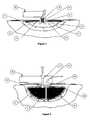
- a more suitable layout for deeper woundsis one in which the pipes, etc. radiate hemispherically and concentrically, to the wound bed.
- suitable forms of such layout of the pipes, etc.include ones in which the pipes, etc. radiate in a flattened hemiellipsoid and concentrically, to the wound bed.
- suitable forms of layout of the pipes, etc.include one which have pipes, tubes or tubules extending from the inlet pipe(s) and/or outlet pipe(s) at the point at which they pass through and/or under the wound-facing face of the backing layer to run over the wound bed. These may have a blind bore with perforations, apertures, holes, openings, orifices, slits or slots along the pipes, etc.
- tubes, pipes or tubulesare resiliently flexible, e.g. elastomeric, and preferably soft, structures with good conformability in the wound and the interior of the wound dressing.
- the layout of the tubes, pipes, tubules, etc.may depend on the depth and/or capacity of the wound.
- examples of suitable forms of such layout of the tubes, pipes, tubules, etc.include ones that consist essentially of one or more of the tubes, etc in a spiral.
- a more suitable layout for deeper wounds when the therapy is applied in this waymay be one that comprises one or more of the tubes, etc in a helix or spiral helix.
- Other suitable layouts for shallower woundsinclude one which have blind-bore, perforated inlet pipe or outlet pipe manifolds that circulate fluid in the wound when the dressing is in use.
- One or both of thesemay be such a form, the other may be, e.g. one or more straight blind-bore, perforated radial tubes, pipes or nozzles.
- Another suitable layoutis one in which
- an inlet pipe and/or outlet pipe manifoldthat delivers the circulating fluid directly to the wound bed or collects the fluid directly from the wound respectively
- inlet manifold and/or outlet manifoldis formed by slots in layers permanently attached to each other in a stack
- the inlet and/or outlet tubes, pipes or tubulesare formed by apertures through layers permanently attached to each other in a stack.
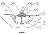
- FIG. 10 athere is shown an exploded isometric view of such a stack, which is non-limiting.
- the backing layer that is appliedmay be any that is appropriate to the present system of therapy and permits a positive or negative pressure of up to 50% atm., more usually up to 25% atm. to be applied to the wound.
- microbe-impermeable film, sheet or membranewhich is substantially flat, depending on any pressure differential on it.
- the backing layermay often have a rigid and/or resiliently inflexible or stiff area to resist any substantial play between other components that are not mutually integral, and may be stiffened, reinforced or otherwise strengthened, e.g. by a projecting boss.
- Such a form of dressingwould not be very conformable to the wound bed, and may effectively form a chamber, hollow or cavity defined by a backing layer and the wound bed under the backing layer.
- one form of the dressingis provided with a wound filler under the backing layer.
- Thisis favourably a resiliently flexible, e.g. elastomeric, and preferably soft, structure with good conformability to wound shape.
- the wound fillermay be integral with the other components of the dressing, in particular the backing layer.
- itmay be permanently attached to them/it, with an adhesive film, for example, or by heat-sealing, e.g. to a flange or lip extending from the proximal face, so a not to disrupt the relatively fluid-tight seal or closure over the wound that is needed.
- an adhesive filmfor example, or by heat-sealing, e.g. to a flange or lip extending from the proximal face, so a not to disrupt the relatively fluid-tight seal or closure over the wound that is needed.
- the wound filleris releasably attached to the backing layer, with an adhesive film, for example, or these components may be a push, snap or twist-lock fit with each other.
- the wound filler and the backing layermay be separate structures, permanently unattached to each other.
- the wound fillermay be or comprise a solid integer, favourably a resiliently flexible, e.g. elastomeric, and preferably soft, structure with good conformability to wound shape.
- suitable forms of such wound fillersare foams formed of a suitable material, e.g. a resilient thermoplastic.
- Preferred materials for the present wound dressinginclude reticulated filtration polyurethane foams with small apertures or pores.
- itmay be in the form of, or comprise one or more conformable hollow bodies defined by a film, sheet or membrane, such as a bag, chamber, pouch or other structure, filled with a fluid or solid that urges it to the wound shape.
- a film, sheet or membranesuch as a bag, chamber, pouch or other structure, filled with a fluid or solid that urges it to the wound shape.
- the film, sheet or membraneoften has a (generally uniform) thickness similar to that of films or sheets used in conventional wound dressing backing layers.
- micronup to 100 micron, preferably up to 50 micron, more preferably up to 25 micron, and of 10 micron minimum thickness, and is often resiliently flexible, e.g. elastomeric, and preferably soft.
- Such a filleris often integral with the other components of the dressing, in particular the backing layer, or permanently attached to them/it, with an adhesive film, for example, or by heat-sealing, e.g. to a flange
- suitable fluids contained in the hollow body or bodies defined by a film, sheet or membraneinclude gases, such as air, nitrogen and argon, more usually air, at a small positive pressure above atmospheric; and liquids, such as water, saline.
- Examplesalso include gels, such as silicone gels, or preferably cellulosic gels, for example hydrophilic cross-linked cellulosic gels, such as IntrasiteTM cross-linked materials.
- gelssuch as silicone gels, or preferably cellulosic gels, for example hydrophilic cross-linked cellulosic gels, such as IntrasiteTM cross-linked materials.
- Examplesalso include aerosol foams, where the gaseous phase of the aerosol system is air or an inert gas, such as nitrogen or argon, more usually air, at a small positive pressure above atmospheric; foams, including set aerosol foams, e.g. CaviCareTM foam, and solid particulates, such as plastics crumbs.
- an inert gassuch as nitrogen or argon, more usually air, at a small positive pressure above atmospheric
- foamsincluding set aerosol foams, e.g. CaviCareTM foam, and solid particulates, such as plastics crumbs.
- the backing layeris a sufficiently conformable and/or e.g. an upwardly dished sheet, the backing layer may lie under the wound filler, rather than vice versa.
- the wound fillerin order for the wound filler to urge the wound dressing towards the wound bed, it will usually have to be firmly adhered or otherwise releasably attached to the skin around the wound. This is especially the case in those embodiments where the wound filler and the backing layer are separate structures, permanently unattached to each other.
- the means for such attachmentmay also form and maintain a seal or closure over the wound.
- the fluid inlet pipe(s) and outlet pipe(s)may run through or around the wound filler over the backing layer.
- a wound fillerunder the backing layer that is or comprises a resiliently flexible, e.g. elastomeric, and preferably soft, hollow body defined by a film, sheet or membrane, such as a bag, chamber, pouch or other structure, with apertures, holes, openings, orifices, slits or slots, or tubes, pipes, tubules or nozzles. It communicates with at least one inlet or outlet pipe through at least one aperture, hole, opening, orifice, slit or slot.
- a resiliently flexiblee.g. elastomeric, and preferably soft, hollow body defined by a film, sheet or membrane, such as a bag, chamber, pouch or other structure, with apertures, holes, openings, orifices, slits or slots, or tubes, pipes, tubules or nozzles.
- the fluid contained in the hollow bodymay then be the circulating fluid in the apparatus.
- the hollow body or each of the hollow bodiesthen effectively forms an inlet pipe or outlet pipe manifold that delivers the circulating fluid directly to the wound bed or collects the fluid directly from the wound respectively via the holes, openings, orifices, slits or slots, or the tubes, pipes or hoses, etc. in the film, sheet or membrane.
- the type of the fillermay also be largely determined by the depth and/or capacity of the wound.
- a more suitable wound filler for deeper wounds when the therapy is applied in this waymay be one which comprises one or more conformable hollow bodies defined by, for example a polymer film, sheet or membrane.
- the latterat least partly surround(s) a solid integer, which may provide a system with better rigidity for convenient handling.
- the wound filler under the backing layermay effectively form an inlet or outlet manifold with a direct connection between the inlet pipe(s) and outlet pipe(s) at the point at which they pass through and/or under the wound-facing face and the wound bed.
- the wound filleris an open-cell foam with pores that may form such bores, channels, conduits, passages and/or spaces through the wound filler under the backing layer.
- the filleris or comprises one or more conformable hollow bodies defined by, for example a polymer film, sheet or membrane, it may be provided with means for admitting fluids to the wound bed under the wound dressing.
- Thesemay be in the form of pipes, tubes, tubules or nozzles running from the point at which the fluid inlet pipe(s) and outlet pipe(s) pass through and/or under the wound-facing face of the backing layer through or around the wound filler under the backing layer.
- suitable layoutsinclude ones where one or both manifolds are
- annular or toroidalregular, e.g. elliptical or circular, or irregular
- blind-boreperforated radial tubes, pipes or nozzles, branching from the annulus or torus; and/or
- the inlet and/or outlet tubes, the fluid recirculation tube and the fluid supply tube, etc.may be of conventional type, e.g. of elliptical or circular cross-section, and may suitably have a uniform cylindrical bore, channel, conduit or passage throughout their length.
- the largest cross-dimension of the boremay be up to 10 mm for large torso wounds, and up to 2 mm for limb wounds.
- the tube wallsshould suitably thick enough to withstand any positive or negative pressure on them.
- the volume of irrigant and/or wound exudate from the wound in recirculationis increased by continuing addition to it of wound exudate, and/or fluid passing from a cleansing fluid through a selectively permeable integer, for example the polymer film, sheet or membrane of a two-phase system, such as an dialysis unit.
- a selectively permeable integerfor example the polymer film, sheet or membrane of a two-phase system, such as an dialysis unit.
- the prime purpose of such tubesis to convey fluid irrigant and exudate through the length of the apparatus flow path, rather than to act as pressure vessels.
- the tube wallsmay suitably be at least 25 micron thick.
- the bore or any perforations, apertures, holes, openings, orifices, slits or slots along the pipes, etc. or in the hollow body or each of the hollow bodiesmay be of small cross-dimension.
- Such tubes, pipes or hoses, etc. through and/or around the filler, whether the latter is a solid integer and/or one or more resiliently flexible or conformable hollow bodies,are described in further detail hereinbefore in connection with the inlet pipe(s) and outlet pipe(s).
- the whole length of the apparatus for irrigating, supplying thermal energy to and/or cleansing woundsshould be microbe-impermeable once the wound dressing is over the wound in use.
- the wound dressing and the interior of the apparatus for irrigating, supplying thermal energy to and/or cleansing wounds of the present inventionis sterile.
- the fluidmay be sterilised in the fluid reservoir and/or the rest of the system in which the fluid recirculates, including the means for fluid cleansing, by ultraviolet, gamma or electron beam irradiation. This way, in particular reduces or eliminates contact of internal surfaces and the fluid with any sterilising agent.
- microapertures or microporese.g. of 0.22 to 0.45 micron maximum cross-dimension, to be selectively impermeable to microbes;
- fluid antisepticssuch as solutions of chemicals, such as chlorhexidine and povidone iodine; metal ion sources, such as silver salts, e.g. silver nitrate; and hydrogen peroxide;
- the interior of the wound dressing, the rest of the system in which the fluid recirculates, and/or the wound bed, even for a wound in a highly exuding stateare kept sterile after the fluid is sterilised in the fluid reservoir, or that at least naturally occurring microbial growth is inhibited.
- materials that are potentially or actually beneficial in this respectmay be added to the irrigant initially, and as desired the amount in recirculation increased by continuing addition.
- antibacterial agentsexamples of such materials include antibacterial agents (some of which are listed above), and antifungal agents.
- triclosanfor example triclosan, iodine, metronidazole, cetrimide, chlorhexidine acetate, sodium undecylenate, chlorhexidine and iodine.
- Buffering agentssuch as potassium dihydrogen phosphate/disodium hydrogen phosphate. may be added to adjust the pH, as may local analgesics/anaesthetics, such as lidocaine/lignocaine hydrochloride, xylocaine (adrenaline, lidocaine) and/or anti-inflammatories, to reduce wound pain or inflammation or pain associated with the dressing.
- local analgesics/anaestheticssuch as lidocaine/lignocaine hydrochloride, xylocaine (adrenaline, lidocaine) and/or anti-inflammatories, to reduce wound pain or inflammation or pain associated with the dressing.
- Examplesinclude the passive deposition of materials that are beneficial in promoting wound healing, such as proteins, e.g. growth factors.
- the fluid contained in the hollow bodymay the deposition of materials that are beneficial in promoting wound healing, and consequent coating,
- coating materials for surfaces over which the circulating fluid passesinclude
- anticoagulantssuch as heparin
- high surface tension materialssuch as PTFE, and polyamides
- the apparatus of the invention for irrigating, supplying thermal energy to and/or cleansing woundsis provided with means for admitting fluids directly or indirectly to the wound under the wound dressing in the form of a fluid supply tube to a fluid reservoir.
- the fluid reservoirmay be of any conventional type, e.g. a tube, bag (such as a bag typically used for blood or blood products, e.g. plasma, or for infusion feeds, e.g. of nutrients), chamber, pouch or other structure, e.g. of polymer film, which can contain the irrigant fluid.
- a tubesuch as a bag typically used for blood or blood products, e.g. plasma, or for infusion feeds, e.g. of nutrients
- chambere.g. of polymer film, which can contain the irrigant fluid.
- the reservoirmay be made of a film, sheet or membrane, often with a (generally uniform) thickness similar to that of films or sheets used in conventional wound dressing backing layers, i.e. up to 100 micron, preferably up to 50 micron, more preferably up to 25 micron, and of 10 micron minimum thickness, and is often a resiliently flexible, e.g. elastomeric, and preferably soft, hollow body.
- a film, sheet or membraneoften with a (generally uniform) thickness similar to that of films or sheets used in conventional wound dressing backing layers, i.e. up to 100 micron, preferably up to 50 micron, more preferably up to 25 micron, and of 10 micron minimum thickness, and is often a resiliently flexible, e.g. elastomeric, and preferably soft, hollow body.
- the type and material of the tubes throughout the apparatus of the invention for irrigating, supplying thermal energy to and/or cleansing wounds and the fluid reservoirwill be largely determined by their function.
- the materialshould be non-toxic and biocompatible, inert to any active components, as appropriate of the irrigant from the fluid reservoir and/or wound exudate in the apparatus flow path, and, in any use of a two-phase system dialysis unit, of the dialysate that moves into the circulating fluid in the apparatus.
- suitable materials for the fluid reservoirinclude synthetic polymeric materials, such as polyolefins, such as polyethylene, e.g. high-density polyethylene and polypropylene.
- Suitable materials for the present purposealso include copolymers thereof, for example with vinyl acetate and mixtures thereof. Suitable materials for the present purpose further include medical grade poly(vinyl chloride).
- the fluid reservoirwill often have a stiff area to resist any substantial play between it and components that are not mutually integral, such as the fluid supply tube towards the wound dressing, and may be stiffened, reinforced or otherwise strengthened, e.g. by a projecting boss.
- the device for moving fluid through the wound and means for fluid cleansingmay be any appropriate for this purpose, and may act at any appropriate point for this purpose.
- the means for fluid cleansingis (most appropriately for its purpose) downstream of the wound dressing, and provides the highest resistance in the flow path. This is especially the case where the means for fluid cleansing is a single-phase system, e.g. with ultrafiltration through microapertures or micropores, thus enhancing applied positive pressure to the wound.
- the deviceWhen the device is applied to the fluid in recirculation in the fluid recirculation tube and/or the fluid in the fluid offtake tube downstream of and away from the wound dressing, it will usually apply negative pressure (i.e. below-atmospheric pressure or vacuum) to the wound bed.
- negative pressurei.e. below-atmospheric pressure or vacuum
- the means for fluid cleansingis (most appropriately for its purpose) downstream of the wound dressing, and provides the highest resistance in the flow path, thus enhancing applied negative pressure to the wound.
- reciprocating pumpssuch as:
- the type and/or capacity of the devicewill be largely determined by
- Such a devicemay also suitably be one that is capable of pulsed, continuous, variable, reversible and/or automated and/or programmable fluid movement. It may in particular be a pump of any of these types.
- Exudate levelsdrop and consistency changes as the wound heals, e.g. to a level for the same wound that equates to 12.5-25 microlitres/cm 2 /hr.
- the balance of fluid in recirculationmay thus further decrease, but may be adjusted to minimise this undesired loss in a routine manner as described hereinbefore.
- the circulating fluid from the woundwill typically contain a preponderance of irrigant over wound exudate in recirculation from the fluid reservoir.
- the type and/or capacity of the devicewill thus be largely determined in this respect by the appropriate or desired fluid volume flow rate of irrigant, rather than that of exudate, from the wound.
- the ‘normal’ irrigation ratewill be different for each dressing size, but the rate of flow of total irrigant and/or wound exudate will be of the order of 1 to 10 ml/cm 2 /24 hour, where the cm 2 refers to the wound area, e.g. 1 to 5 ml/ cm 2 /24 hour, such as 1 to 3.5 ml hr.
- the necessary target temperature at the heater outletmay be achieved by adjusting parameters, such as increasing or decreasing the linear flow rate of the irrigant and/or any heat exchanger fluid or the temperature of the heater in a routine manner known to the skilled person.
- the interior of the wound dressing and the rest of the system in which the fluid recirculatesbe flushed cyclically before and/or after use in treatment, to cleanse them, and it is convenient that this is effected by the device for moving fluid through the wound and means for fluid cleansing.
- the devicemay deliver a flush cycle at an irrigation rate substantially greater than the ‘normal’ rate; this could typically be up to 650 ml/hr for the largest dressing size. It may be desirable therefore that the apparatus adjusts the heat energy delivered to the wound in accordance with the selected irrigant/exudate flow rates at any moment in time.
- the volume of irrigant and/or wound exudate in recirculationmay vary over a wide range, but will typically be e.g. 1 to 8 l. (for example for large torso wounds), 30 to 300 ml (for example for axillary and inguinal wounds), and 200 to 1500 ml for limb wounds when the therapy is applied in this way.
- suitable pressuresare of the order of up to 25% atm such as up to 10% atm. positive or negative pressure on the wound bed, the apparatus being operated as a closed recirculating system.
- the lower endis potentially more suitable for home use, where relatively high % pressures and/or vacua cannot be used safely without professional supervision, or for field hospital use.
- the devicemay be a peristaltic pump or diaphragm pump, e.g. preferably a small portable diaphragm or peristaltic pump. These are preferred types of pump, in order in particular to reduce or eliminate contact of internal surfaces and moving parts of the pump with (chronic) wound exudate, and for ease of cleaning.
- a preferred pump when the applied pressure is positiveis a peristaltic pump, e.g. a small, portable peristaltic pump, mounted upstream of the means for fluid cleansing.
- the pumpis a peristaltic pump
- thismay be e.g. an Instech Model P720 miniature peristaltic pump, with a flow rate: of 0.2-180 ml/hr and a weight of ⁇ 0.5 k. This is potentially useful for home and field hospital use.
- the pumpmay suitably be one that applies negative pressure to the wound and/or the means for fluid cleansing.
- a preferred pump when the applied pressure is negativeis a diaphragm pump, e.g. a small, portable diaphragm pump, mounted downstream of the dressing or the means for fluid cleansing.
- the one or two flexible diaphragms that displace liquidmay each be, for example a polymer film, sheet or membrane, that is connected to means for creating the pulsations.
- Thismay be provided in any form that is convenient, inter alia as a piezoelectric transducer, a core of a solenoid or a ferromagnetic integer and coil in which the direction of current flow alternates, a rotary cam and follower, and so on.
- the outlet from the dressingpasses to the means for fluid cleansing for removal of materials deleterious to wound healing from wound exudate, and in turn to the fluid recirculation tube(s).
- the apparatus of the invention for irrigating, supplying thermal energy to and/or cleansing woundsis provided with means for fluid cleansing, which may be
- the single-phase systemmay be of any conventional type.
- ultrafiltration unitsuch as a one in which the cleansing integer is a filter for materials deleterious to wound healing, for example a high throughput, low protein-binding polymer film, sheet or membrane which is selectively impermeable to materials deleterious to wound healing, which are removed and the cleansed fluid, still containing materials that are beneficial in promoting wound healing is passed by it.
- the cleansing integeris a filter for materials deleterious to wound healing, for example a high throughput, low protein-binding polymer film, sheet or membrane which is selectively impermeable to materials deleterious to wound healing, which are removed and the cleansed fluid, still containing materials that are beneficial in promoting wound healing is passed by it.
- the membranemay preferably be of a hydrophilic polymeric material, such as a cellulose acetate-nitrate mixture, polyvinylidene chloride, and, for example hydrophilic polyurethane.
- a hydrophilic polymeric materialsuch as a cellulose acetate-nitrate mixture, polyvinylidene chloride, and, for example hydrophilic polyurethane.
- hydrophobic materialsalso including polyesters, such as polycarbonates, PTFE, and polyamides, e.g. nylon 6-6 and 6-10, and hydrophobic polyurethanes, and quartz and glass fibre.
- microapertures or microporesthe maximum cross-dimension of which will largely depend on the species that are to be selectively removed in this way and those to which it is to be permeable.
- the formermay be removed with microapertures or micropores, e.g. typically with a maximum cross-dimension in the range of 20 to 700 micron, e.g. 20 to 50 nm (for example for undesired proteins), 50 to 100 nm, 100 to 250 nm, 250 to 500 nm and 500 to 700 nm.
- microapertures or microporese.g. typically with a maximum cross-dimension in the range of 20 to 700 micron, e.g. 20 to 50 nm (for example for undesired proteins), 50 to 100 nm, 100 to 250 nm, 250 to 500 nm and 500 to 700 nm.
- the filter integermay be a flat sheet or a membrane of a polymeric material in a more convoluted form, e.g. in the form of elongate structure, such as pipes, tubules, etc.
- the systemmay be a chemical adsorption unit, for example one in which a particulate, such as a zeolite, or a layer, e.g. of a functionalised polymer has sites on its surface that are capable of removing materials deleterious to wound healing on passing the circulating fluid from the wound and the fluid reservoir over them.
- a particulatesuch as a zeolite
- a layere.g. of a functionalised polymer has sites on its surface that are capable of removing materials deleterious to wound healing on passing the circulating fluid from the wound and the fluid reservoir over them.
- the materialsmay be removed, e.g. by destroying or binding the materials that are deleterious to wound healing, by, for example chelators and/or ion exchangers, degraders, which may be enzymes.
- Examples of suchalso include less specific chemical adsorption units, for example one in which a physical absorbent, such as activated carbon or a zeolite, has non-specific sites on its surface that are capable of removing materials deleterious to wound healing on passing the circulating fluid from the wound and the fluid reservoir over them.
- a physical absorbentsuch as activated carbon or a zeolite
- the cleansing integerfor example the polymer film, sheet or other chemical adsorption means, etc should of course be capable of removing materials deleterious to wound healing at a practical rate for a given capacity of the apparatus flow path and the flow rate of irrigant.
- circulating fluid from the wound and the fluid reservoirin indirect or (less usually, direct) contact with a second fluid (dialysate) phase, more usually a liquid.
- a biphasic liquid extraction unitthe second fluid phase is (usually) a liquid that is immiscible with the circulating fluid from the dressing, over a surface of which the circulating fluid passes in direct contact with the cleansing fluid. Materials deleterious to wound healing are removed into the dialysate, and the cleansed fluid, still containing materials that are beneficial in promoting wound healing, is returned via the recirculation tube to the wound bed.
- Examples of such means for fluid cleansinginclude those wherein the second fluid (dialysate) phase is perfluorodecalin and like materials
- the two fluidsrecirculation fluid and dialysate
- a significantly two-dimensional integerfor example a polymer film, sheet or membrane or hollow fibre or filament that is permeable to materials in the circulating fluid in the apparatus.
- the dialysatemoves past the circulating fluid in the apparatus in a co- or preferably counter-current direction.
- Pumpssuch as peristaltic pumps, and/or valves control the direction of the two fluid flows.
- the cleansing fluidmay less usually be static, although this may not provide a system with sufficient (dynamic) surface area to remove materials deleterious to wound healing from wound exudate at a practical rate.
- Typical dialysate flow rates in a dialytic means for fluid cleansing in the present apparatus for irrigating, supplying thermal energy to and/or cleansing woundsare those used in the conventional type of two-phase system, such as a dialysis unit for systemic therapy.
- the integermay be a film, sheet or membrane, often of the same type, and of the same (generally uniform) thickness, as those used in conventional two-phase system, such as a dialysis unit for systemic therapy.
- the film, sheet or membranemay be substantially flat, and depending on any pressure differential across it may require other materials on or in it to stiffen, reinforce or otherwise strengthen it.
- the surface area of any such film, sheet or membranemay be suitably be no less than 50 mm 2 , such 100 mm 2 to 1 m 2 , e.g. 500 to 25000 mm 2.
- Thismay be in the form of elongate structures, such as pipes, tubes hollow fibres or filaments or tubules of a round cross-section, e.g. elliptical or circular, e.g. in a parallel array with spaces therebetween.
- the wound irrigant and/or wound exudatemay recirculate through the inside and the cleansing fluid may pass into the spaces between adjacent pipes, tubes or tubules in a co- or preferably counter-current direction, or vice versa.
- the means for fluid cleansingis a two-phase system, e.g. in the form of a dialysis unit, or a biphasic extraction unit
- the circulating fluid from the wound and the fluid reservoirpasses across one surfaces of a significantly two-dimensional integer, for example a polymer film, sheet or membrane which is selectively permeable to materials deleterious to wound healing.
- the integermay be a film, sheet or membrane that is selectively permeable to the foregoing materials deleterious to wound healing.
- suitable materials for the film, sheet or membraneinclude natural and synthetic polymeric materials.
- the membranemay be of one or more hydrophilic polymeric materials, such as a cellulose derivative, e.g. regenerated cellulose, a cellulose mono-, di- or tri-esters, such as cellulose mono-, di- or tri-acetate, benzyl cellulose and Hemophan, and mixtures thereof.
- a cellulose derivativee.g. regenerated cellulose
- a cellulose mono-, di- or tri-esterssuch as cellulose mono-, di- or tri-acetate, benzyl cellulose and Hemophan, and mixtures thereof.
- hydrophobic materialssuch as aromatic polysulphones, polyethersulphones, polyetherether-sulphones, polyketones, polyetherketones and polyetherether-ketones, and sulphonated derivatives thereof, and mixtures thereof.
- hydrophobic materialssuch as polyesters, such as polycarbonates and polyamides, e.g. Nylon 6-6 and 6-10; polyacrylates, including, e.g. poly(methyl methacrylate), polyacrylonitrile and copolymers thereof, for example acrylonitrile-sodium metallosulphonate copolymers; and poly(vinylidene chloride).
- Suitable materials for the present membranesinclude thermoplastic polyolefins, such as polyethylene e.g. high-density polyethylene, polypropylene, copolymers thereof, for example with vinyl acetate and polyvinyl alcohol, and mixtures thereof.
- thermoplastic polyolefinssuch as polyethylene e.g. high-density polyethylene, polypropylene, copolymers thereof, for example with vinyl acetate and polyvinyl alcohol, and mixtures thereof.
- the dialysis membraneshould have a molecular weight cut off (MWCO) chosen to allow selective perfusion of species deleterious to wound healing that have been targeted for removal from the wound.
- MWCOmolecular weight cut off
- perfusion of the serine protease elastasewould require a membrane with MWCO>25900 Dalton.
- the MWCO thresholdcan be varied to suit each application between 1 and 3000000 Dalton.
- the MWCOshould be as close as possible to this weight to exclude interference by larger competitor species.
- such a membrane with MWCO>25900 Daltondoes not allow any significant amounts of the antagonist to elastase, alpha-1-antitrypsin (AAT) (molecular weight 54000 Dalton), which occurs naturally in wounds, to diffuse freely out of the wound fluid into the dialysate.
- AATalpha-1-antitrypsin
- the inhibitorwhich is beneficial in promoting chronic wound healing, remains in contact with the wound bed, and can act beneficially on it, whilst the elastase that is deleterious to wound healing is removed.
- Such use of the present apparatusis, e.g. favourable to the wound healing process in chronic wounds, such as diabetic foot ulcers, and especially decubitus pressure ulcers.
- antagonistsfor example degrading enzymes, or sequestrating agents for elastase on the dialysate side of the membrane, may be used to enhance the removal of this protease from wound exudate.
- any such systemis a conventional automated, programmable system which can cleanse the wound irrigant and/or wound exudate with minimal supervision.
- fluidpasses from a cleansing fluid through a selectively permeable integer.
- Thismay be the typical permeable polymer film, sheet or membrane of a two-phase system, such as a dialysis unit.
- solutes or disperse phase specieswill pass from the dialysate into the irrigant and/or wound exudate through the dialysis polymer film, sheet or membrane.
- This propertymay be used to perfuse materials beneficial to wound healing into the irrigant and/or exudate from a dialysate.
- both the single-phase systemsuch as an ultrafiltration unit
- two-phase systemsuch as a dialysis unit
- captive (non-labile, insoluble and/or immobilised) speciessuch as the following.
- Suitable chelators and/or ion exchangers, degraderswhich may be enzymes, or other species.
- the following types of functionalised substratehas sites on its surface that are capable of removing materials deleterious to wound healing on passing the circulating fluid from the wound and the fluid reservoir over them:
- heterogeneous resinsfor example silica-supported reagents such as: metal scavengers,
- a backing layer in the wound dressing with ribs or ridgesmay be used to assist in channelling fluid across a larger area over a longer dwell time, and hence improve the cleansing of the irrigant in the wound dressing.
- the means for fluid cleansingmay additionally, where appropriate, comprise one or more macroscopic and/or microscopic filters.
- a less conventional type of two-phase systemsuch as a dialysis unit, may be used as the means for fluid cleansing.
- the dialysis polymer film, sheet or membraneis not an integer selectively permeable to materials deleterious to wound healing, such as
- proteasessuch as serine proteases, e.g. elastase, trypsin; chymotrypsin and thrombin; cysteine protease inhibitors; matrix metalloproteases, e.g. collagenase; and carboxyl (acid) proteases;
- endotoxinssuch as lipopolysaccharides
- angiogenesissuch as thrombospondin-1 (TSP-1), plasminogen activator inhibitor, or angiostatin (plasminogen fragment);
- TSP-1thrombospondin-1
- plasminogen activator inhibitorplasminogen activator inhibitor
- angiostatinplasminogen fragment
- cytokinessuch as tumour necrosis factor alpha (TNF ⁇ ) and interleukin 1 beta (IL-1 ⁇ ); and
- oxidantssuch as free radicals, e.g., e.g. peroxide and superoxide; metal ions, e.g. iron II and iron III; all involved in oxidative stress on the wound bed.
- dialysateor preferably in one or more solid structural integers with at least one surface in contact with the dialysate, in the means for fluid cleansing, there are one or more materials that can remove materials deleterious to wound healing from wound exudate, by being
- protease inhibitorssuch as serine protease inhibitors, such as 4-(2-aminoethyl)-benzene sulphonyl fluoride (AEBSF, PefaBloc) and N ⁇ -p-tosyl-L-lysine chloromethyl ketone (TLCK) and ⁇ -aminocaproyl-p-chlorobenzylamide; cysteine protease inhibitors; matrix metalloprotease inhibitors; and carboxyl (acid) protease inhibitors;
- serine protease inhibitorssuch as 4-(2-aminoethyl)-benzene sulphonyl fluoride (AEBSF, PefaBloc) and N ⁇ -p-tosyl-L-lysine chloromethyl ketone (TLCK) and ⁇ -aminocaproyl-p-chlorobenzylamide
- cysteine protease inhibitorssuch as matrix metalloprotease inhibitors; and carboxyl (a
- peroxide inhibitorssuch as catalase
- binders and/or degraderssuch as anti-inflammatory materials to bind or destroy lipopolysaccharides, e.g. peptidomimetics;
- anti-oxidantssuch as 3-hydroxytyramine (dopamine), ascorbic acid (vitamin C), vitamin E and glutathione, and stable derivatives thereof, and mixtures thereof; to relieve oxidative stress on the wound bed; and
- chelators and/or ion exchangessuch as desferrioxamine (DFO), 3-hydroxytyramine (dopamine).
- cytokinese.g. bacterial cytokines, such as ⁇ -amino- ⁇ -butyrolactone and L-homocarnosine
- cytokinese.g. bacterial cytokines, such as ⁇ -amino- ⁇ -butyrolactone and L-homocarnosine
- sacrificial redox materialsthat are potentially or actually beneficial in promoting wound healing, such as iron III reductants; and/or remove materials that trigger the expression into wound exudate of redox-sensitive genes, by degrading them;
- Some (mainly ionic) specieswill pass from the dialysate into the irrigant and/or wound exudate through the dialysis polymer film, sheet or membrane that is not very selectively permeable to materials deleterious to wound healing.
- the components of the exudate from a wound and/or irrigant fluidwill diffuse freely to and fro through it.
- Circulating wound fluidaids in the quicker attainment of this equilibrium of materials beneficial in promoting wound healing.
- the target materials deleterious to wound healingalso pass into the dialysate from the exudate through the dialysis polymer film, sheet or membrane that is not very selectively permeable to materials deleterious to wound healing.
- the target materials deleterious to wound healingcome into contact with the dialysate, or preferably with one or more solid structural integers with at least one surface in the dialysate, and are removed by the appropriate antagonists, binders and/or degraders, chelators and/or ion exchangers and redox agents, etc.
- the cleansed fluidstill containing some materials that are beneficial in promoting wound healing, is returned to the recirculation tube.
- the target materialsare constantly removed from the dialysate, very little of these species will pass from the dialysate, into the irrigant and/or wound exudate, and a steady state concentration equilibrium is not set up, even if the species are constantly ‘topped up’ from the wound dressing.
- circulating wound fluidaids in removal from recirculation of the materials deleterious to wound healing from wound exudate, whilst retaining materials that are beneficial in promoting wound healing in contact with the wound.
- a particular advantage of this form of the two-phase systemis where a material that can remove materials deleterious to wound healing from wound exudate is (cyto)toxic or bioincompatible, or not inert to any components that are beneficial in promoting wound healing.
- the systemdoes not allow any significant amounts of antagonist to diffuse freely out of the dialysate into the irrigant fluid.
- the active materialcan act beneficially on the fluid however.
- the film sheet or membraneis preferably a dialysis membrane of molecular weight cut off (MWCO) chosen to allow perfusion of species targeted for sequestration or destruction.
- MWCOmolecular weight cut off
- sequestration of the serine protease elastasewould require a membrane with MWCO>25900 Dalton.
- the MWCO thresholdcan be varied to suit each application between 1 and 3000000 Dalton.
- the MWCOshould be as close as possible to this weight to exclude sequestering interference by larger competitor species.
- Both the single-phase system, such as an ultrafiltration unit, and two-phase system, such as a dialysis unit,may be in modular form that is relatively easily demountable from the apparatus of the invention.
- the systemmay suitably comprise one or more such modules.
- the apparatus of the invention for irrigating, supplying thermal energy to and/or cleansing woundsis provided with means for bleeding the offtake and/or recirculation tubes, such as a regulator, such as a valve or other control device for bleeding fluids from the wound.
- a regulatorsuch as a valve or other control device for bleeding fluids from the wound.
- the device for moving fluid through the wound and means for fluid cleansingis used to move irrigant to the wound dressing and apply the desired positive or negative pressure on the wound bed.
- the desired balance of fluid in recirculation tubewill typically be regulated by means of
- the apparatusmay be operated as a closed recirculating system.
- the means for flow switching between supply and recirculation tubesis set to close the wound to the fluid reservoir via the fluid supply tube, and the means for bleeding the offtake and/or recirculation tubes are also closed.
- the apparatuscannot be operated as a closed recirculating system, without the pressure to the wound bed increasing, possibly undesirably.
- the means for bleeding the offtake and/or recirculation tubesmust be opened to some extent to relieve positive pressure on the wound bed.
- the bleed-offmay be voided to waste, e.g. to a collection bag.
- Materials that are beneficial in promoting wound healingmay be lost to the site where they can be potentially of most benefit, i.e. the wound bed, when the therapy is applied in this way.
- the outlet from the means for bleeding the offtake and/or recirculation tubesmay be collected and monitored and used to diagnose the status of the wound and/or its exudate.
- the waste reservoirmay be of any conventional type, e.g. a tube, bag (such as a bag typically used as an ostomy bag), chamber, pouch or other structure, e.g. of polymer film, which can contain the irrigant fluid that has been bled off.
- a tubesuch as a bag typically used as an ostomy bag
- a pouchor other structure, e.g. of polymer film, which can contain the irrigant fluid that has been bled off.
- the type and material of the waste reservoirwill be largely determined by its function. To be suitable for use, the material need only be fluid-impermeable once in use, and flexible.
- suitable materials for the fluid reservoirinclude synthetic polymeric materials, such as polyolefins, such as poly (vinylidene chloride).
- Suitable materials for the present purposealso include polyethylene, e.g. high-density polyethylene, polypropylene, copolymers thereof, for example with vinyl acetate and mixtures thereof.
- a conformable wound dressingcharacterised in that it comprises a backing layer with a wound-facing face which is capable of forming a relatively fluid-tight seal or closure over a wound and has
- the dressingis advantageously provided for use in a bacteria-proof pouch.
- suitable forms of such wound dressingsare as described by way of example hereinbefore.
- a method of treating wounds to promote wound healingusing the apparatus for irrigating, supplying thermal energy to and/or cleansing wounds of the present invention.
- FIG. 1is a schematic view of an apparatus for irrigating, supplying thermal energy to and/or cleansing a wound according to the first aspect of the present invention.
- FIG. 2is a schematic view of an apparatus for irrigating, supplying thermal energy to and/or cleansing a wound according to the first aspect of the present invention.
- Ithas a two-phase system means for fluid cleansing in the form of a dialysis unit, or a biphasic extraction unit.
- the means for supplying conducted thermal energyare omitted from the schematics for clarity.
- FIGS. 3 to 6are cross-sectional side views of conformable wound dressings, of the second aspect of the present invention for aspirating and/or irrigating wounds.
- FIG. 7is a schematic view of an apparatus for aspirating, irrigating and/or cleansing a wound according to the first aspect of the present invention. It has a single-phase system means for fluid cleansing in the form of an ultrafiltration unit.
- FIG. 8is a schematic view of an apparatus for aspirating, irrigating and/or cleansing a wound according to the first aspect of the present invention. It has a two-phase system means for fluid cleansing in the form of a dialysis unit, or a biphasic extraction unit.
- FIG. 9is a schematic view of another apparatus for aspirating, irrigating and/or cleansing a wound according to the first aspect of the present invention. It has a single-phase system means for fluid cleansing in the form of an ultrafiltration unit.
- the apparatus ( 1 ) for irrigating, supplying thermal energy to and/or cleansing woundscomprises
- the ultrafiltration unit ( 17 )is a single-phase system.
- the circulating fluid from the wound and the fluid reservoirpasses through a self-contained system in which materials deleterious to wound healing are removed and the cleansed fluid, still containing materials that are beneficial in promoting wound healing, is returned via the recirculation tube to the wound bed.
- inlet pipes ( 6 )there are two inlet pipes ( 6 ), which are connected respectively to a fluid supply tube ( 7 ) and fluid recirculation tube ( 13 ), respectively having a first valve ( 19 ) for admitting fluid into the wound from the fluid reservoir ( 12 ) and a second valve ( 20 ) for admitting fluid into the wound from the recirculation tube.
- first valve ( 19 )for admitting fluid into the wound from the fluid reservoir ( 12 )
- second valve ( 20 )for admitting fluid into the wound from the recirculation tube.
- valve ( 16 )In use of the apparatus ( 1 ), the valve ( 16 ) is opened to a collection bag (not shown), and the T-valve ( 14 ) is turned to admit fluid from the fluid reservoir to the wound dressing through the fluid supply tube ( 7 ) and inlet pipe ( 6 ).
- the pump ( 18 )is started to nip the fluid recirculation tube ( 13 ) with the peripheral rollers on its rotor (not shown) to apply a low positive pressure on the wound. It is allowed to run until the apparatus is primed throughout the whole length of the apparatus flow path and excess fluid is voided to waste via the bleed T-valve ( 16 ) into the collection bag (not shown).
- the electrical heater ( 111 ) on inlet pipe ( 6 )is turned on to supply conducted thermal energy to the fluid in the wound.
- the T-valve ( 14 )is then turned to switch from supply and recirculation, i.e. is set to close the wound to the fluid reservoir ( 12 ) but to admit fluid into the wound from the fluid recirculation tube ( 13 ), and the bleed T-valve ( 16 ) is simultaneously closed.
- the circulating fluid from the wound and the fluid reservoir ( 12 )passes through the ultrafiltration unit ( 17 ). Materials deleterious to wound healing are removed and the cleansed fluid still containing materials that are beneficial in promoting wound healing, is returned via the recirculation tube ( 13 ) to the wound bed.
- the recirculation of fluidmay be continued as long as desired.
- the bleed valve ( 16 )is simultaneously opened, so that fresh fluid flushes the recirculating system.
- the running of the pump ( 18 )may be continued until the apparatus is flushed, when it and the fluid recirculation is stopped, and the electrical heater ( 111 ) on inlet pipe ( 6 ) is turned off.
- the apparatus ( 21 )is a variant of that of FIG. 1 , with identical, and identically numbered, components, except for the means for fluid cleansing, which is in the form of a two-phase system, here a dialysis unit ( 23 ).
- the dialysis unit ( 23 )thus has an internal polymer film, sheet or membrane ( 24 ), selectively permeable to materials deleterious to wound healing, which divides it into
- the dialysis unit ( 23 )thus has a dialysate inlet pipe ( 28 ) connecting to a dialysate supply tube ( 29 ) which passes to a peristaltic pump ( 38 ), e.g. preferably a small portable peristaltic pump, acting on the dialysate supply tube ( 29 ) with the peripheral rollers on its rotor (not shown) to supply cleansing fluid across the surface of the polymer film, sheet or membrane ( 28 ) in the first chamber ( 25 ) from a dialysate reservoir (not shown) via a valve ( 34 ).
- a peristaltic pump38
- a peristaltic pumpe.g. preferably a small portable peristaltic pump
- the dialysis unit ( 23 )also has a dialysate outlet pipe ( 30 ) connecting to a dialysate outlet tube ( 31 ) which passes to waste via a second bleed T-valve ( 36 ) into, e.g. a collection bag (not shown).
- the pump ( 38 )is started to nip fluid dialysate tube ( 29 ) with the peripheral rollers on its rotor (not shown) to pump cleansing fluid to the first chamber from a dialysate reservoir (not shown) and out to waste via the bleed valve ( 36 ) into the collection bag (not shown).
- the dialysis unit ( 23 )is a module (or scrubbing cartridge) with a substrate that changes colour to indicate the presence of detrimental factors in the cleansed fluid, and that the scrubbing cartridge is exhausted and should be renewed.
- each dressing ( 41 )is in the form of a conformable body defined by a microbe-impermeable film backing layer ( 42 ) with a uniform thickness of 25 micron, with a wound-facing face ( 43 ) which is capable of forming a relatively fluid-tight seal or closure over a wound.
- the backing layer ( 42 )extends in use on a wound over the skin around the wound.
- inlet pipe ( 46 )for connection to a fluid supply tube (not shown), which passes through and/or under the wound-facing face ( 43 ), and one outlet pipe ( 47 ) for connection to a fluid offtake tube (not shown), which passes through and/or under the wound-facing face ( 43 ),
- one form of the dressingcomprises a circular sheet ( 70 ) that lies under a circular backing layer ( 72 ) and is permanently attached to a boss ( 81 ), which is e.g. heat-sealed to the backing layer ( 72 ).
- a suitable materiale.g. a resilient thermoplastic, preferably a reticulated filtration polyurethane foam with small apertures or pores
- a downwardly dished membrane ( 75 ) with openings ( 76 )is permanently attached to the sheet ( 70 ) by heat-sealing to form a chamber ( 77 ) with the sheet ( 70 ).
- An inlet pipe ( 76 ) and outlet pipe ( 77 )are mounted centrally in the boss ( 81 ) and pass through the backing layer ( 72 ).
- the inlet pipe ( 76 )is made of a polyurethane tubular core (not shown) surrounded by an annulus of resistive conductive material, such as one of the resistive alloys noted hereinbefore, which generates thermal energy when a voltage drop is applied over it. It is connected to a cell ( 78 ), shown schematically, which applies a voltage drop over it.
- the inlet pipe ( 76 )communicates with the interior of the chamber ( 77 ), which thus forms an inlet manifold that distributes heated fluid directly to the wound when the dressing is in use.
- the outlet pipe ( 77 )extends radially immediately under the backing layer ( 3 ) and communicates with the inner face of the layer of foam ( 74 ), which forms an outlet manifold.
- This form of the dressingis a more suitable layout for shallow wounds
- FIG. 4Another form of dressing is shown in FIG. 4 .
- An inlet pipe ( 76 ) and outlet pipe ( 77 )are mounted centrally in a boss ( 81 ) in, and pass through a backing layer ( 3 ).
- An oblately hemispheroidal filler ( 88 ) with an annular groove ( 89 )may be permanently attached to the pipes ( 76 ) and ( 77 ). It is formed of a suitable material, e.g. a resilient thermoplastic foam, preferably a reticulated filtration polyurethane foams with small apertures or pores.
- An annular electrical heat pad ( 90 )is mounted around the boss ( 81 ) on top of the backing layer ( 3 ), which is capable of conducting heat to the wound ( 5 ) through the irrigant.
- non-woven or woven fabricsuch as a woven layer or sheet of carbon fibres or a fabric, such as a woven layer or sheet made essentially of carbonised acrylate, such as polyacrylonitrile and copolymers thereof, which generate thermal energy when a voltage drop is applied over it.
- itmay be an electrically insulating flat sheet or membrane substrate that has an electrically resistive but conductive printed circuit on it. It is connected to a cell ( 78 ), shown schematically, which applies a voltage drop over it.
- the inlet pipe ( 76 )communicates with the wound space at the lowest point of the filler ( 88 ).
- the outlet pipe ( 77 )communicates with the groove ( 89 ), and effectively collects the fluid from the wound periphery when the dressing is in use.
- This form of the dressingis a more suitable layout for deeper wounds.
- an inlet pipe ( 76 ) and outlet pipe ( 77 )are mounted centrally in a boss ( 81 ) in, and pass through a backing layer ( 3 ).
- An oblately spheroidal conformable hollow body ( 78 )is defined by a membrane ( 79 ) which is filled with a fluid, here air or nitrogen, that urges it to the wound shape, and is permanently attached to the pipes ( 76 ) and ( 77 ). It is formed of a suitable material, e.g. a resilient thermoplastic, preferably a reticulated filtration polyurethane foam with small apertures or pores.
- the inflation inlet pipe ( 350 )communicates with the interior of the hollow body ( 78 ), to permit inflation of the body ( 78 ).
- the inlet pipe ( 76 )extends through the hollow body ( 78 ).
- the outlet pipe ( 77 )communicates with an outlet manifold formed by a series of radial apertures in a foam disc ( 87 ) immediately under the backing layer, which collects the fluid from the wound periphery when the dressing is in use.
- An electrical heater ( 90 )is mounted under the boss ( 81 ) on top of the backing layer ( 3 ), which is transparent to radiant heat, and so permit its transmission to the wound ( 5 ) through the irrigant.
- Itmay be in the form of a near infrared radiant heater that generates thermal energy when a voltage drop is applied over it. It is connected to a cell ( 78 ), shown schematically, which applies a voltage drop over it.
- FIG. 6 aanother form for deeper wounds is shown.
- Thiscomprises a circular, or more usually square or rectangular, backing layer ( 342 ) and a chamber ( 363 ) in the form of a deeply indented disc much like a multiple Maltese cross or a stylised rose.
- FIG. 6 bThree configurations of the chamber ( 363 ) are shown in FIG. 6 b , all of which are able to conform well to the wound bed by the arms closing in and possibly overlapping in insertion into the wound.
- the space above the chamber ( 363 )is filled with a wound filler ( 348 ) under the backing layer ( 342 ).
- Thiscomprises an oblately spheroidal conformable hollow body, defined by a membrane ( 349 ) that is filled with a fluid, here air or nitrogen, that urges it to the wound shape.
- a moulded hat-shaped boss ( 351 )is mounted centrally on the upper impervious membrane ( 361 ) of the chamber ( 363 ). It has three internal channels, conduits or passages through it (not shown), each with entry and exit apertures.
- the filler ( 348 )is attached to the membrane ( 361 ) of the chamber ( 363 ) by adhesive, heat welding or a mechanical fixator, such as a cooperating pin and socket.
- An inflation inlet pipe ( 350 ), inlet pipe ( 346 ) and outlet pipe ( 347 )pass under the edge of the proximal face of the backing layer ( 342 ) of the dressing, and extend radially immediately under the filler ( 348 ) and over the membrane ( 361 ) of the chamber ( 363 ) to each mate with an entry aperture in the boss ( 351 ).
- An exit to the internal channel, conduit or passage that receives the inlet pipe ( 346 )communicates with the interior of the chamber ( 363 ) to deliver the irrigant fluid via the chamber ( 363 ) to the wound bed over an extended area.
- an exit to the internal channel, conduit or passage that receives the outlet pipe ( 347 )communicates with the space above the chamber ( 363 ) and under the wound filler ( 348 ), and collects flow of irrigant and/or wound exudate radially from the wound periphery.
- the inlet pipe ( 346 )is permanently attached to, and communicate with the interior of, a recirculation tube ( 413 ) in the form of a spiral or loop or a more convoluted form.
- a recirculation tube ( 413 )in the form of a spiral or loop or a more convoluted form.
- Thisis a meandering, tortuous or winding path (not shown) sandwiched between parallel electrically heated plates of resistive conductive material, such as a resistive alloys (also not shown), all within a moulded disc-shape housing case ( 416 ).
- Thishas entry and exit apertures in the edge extending between the faces of the case, through which the irrigant tubing passes.
- the heated platesconnected to a cell ( 419 ) shown schematically, which applies a voltage drop over them in use.
- the boss ( 351 ) mounted centrally on the upper impervious membrane ( 361 ) of the chamber ( 363 )may also include a lumen through it (not shown in the Figure) with entry and exit apertures.
- a fourth pipemay also pass under the edge of the proximal face of the backing layer ( 342 ) of the dressing, and extend radially immediately under the filler ( 348 ) and over the membrane ( 361 ) of the chamber ( 363 ) to mate with the lumen entry aperture in the boss ( 351 ).
- An exit to the internal channel, conduit or passage through it that receives this pipemay communicate with the space above the chamber ( 363 ) and under the wound filler ( 348 ), to permit the monitoring of wound pressure.
- the apparatus ( 1 ) for aspirating, irrigating and/or cleansing woundsis a variant of the apparatus ( 1 ) of FIG. 1 .
- An alternative to the by-pass ( 711 )is a pressure sensor for the monitoring of pressure in the system and a control feedback circuit for its regulation, e.g. a pressure sensor at a point in the wound space for the monitoring of negative pressure there, which communicates with a control feedback circuit that will shut down the pump when the sensor detects excessive negative pressure.
- a pressure sensor for the monitoring of pressure in the system and a control feedback circuit for its regulationis depicted in FIG. 9 .
- Another alternative to the by-pass ( 711 )is a pressure sensor mounted downstream of the pump for the monitoring of positive pressure there, which communicates with a control feedback circuit that will shut down the pump when the sensor detects excessive positive pressure from resistance, e.g. in the means for fluid cleansing that is likely to cause the system to fail catastrophically (e.g. burst tubes).
- the apparatus ( 1 ) for aspirating, irrigating and/or cleansing woundsis a variant of the apparatus ( 1 ) of FIG. 2 .
- the latteris a two-phase system with a dialysis unit ( 21 ), but is one in which dialytic fluid passes only once across the surface of the dialytic membrane ( 28 ) in the first chamber ( 25 ) from a dialysate reservoir (not shown) to waste via a second bleed T-valve ( 36 ) into, e.g. a collection bag (not shown).
- This varianthas a dialysate recirculation tube ( 811 ) running between a first T-valve ( 816 ) on the inlet side of the dialysate pump ( 23 ) and a second T-valve ( 817 ) to permit the pump ( 23 ) to recirculate the dialysate once the circuit is primed in multiple passes through the dialysis unit ( 21 ).
- the apparatus ( 1 ) for aspirating, irrigating and/or cleansing woundsis a major variant of the apparatus shown in FIG. 1 .
- the device for moving fluid through the wound and means for fluid cleansing ( 17 ) in FIG. 1is a peristaltic pump ( 18 ), e.g. preferably a small portable peristaltic pump, acting on the fluid circulation tube ( 13 ) downstream of the dressing ( 2 ) to apply an overall low negative pressure in the wound space.
- a peristaltic pump18
- a small portable peristaltic pumpacting on the fluid circulation tube ( 13 ) downstream of the dressing ( 2 ) to apply an overall low negative pressure in the wound space.
- the peristaltic pump ( 18 )is replaced by:
- the vacuum pump assemblycomprises a tank ( 911 ) with
- the vacuum pump ( 918 )is controlled by a pressure feedback regulator ( 919 ) through an electrical line ( 920 ), the regulator receiving signals from a tank sensor ( 921 ) in the upper part of the tank ( 911 ), and a dressing sensor ( 922 ) in the wound space respectively via lines ( 923 ) and ( 924 ).
- the waste pump ( 914 )is controlled by a waste level feedback regulator ( 929 ) the regulator receiving signals from a tank sensor with electrical line ( 930 ) in the middle part of the tank ( 911 ).
- the vacuum pump ( 918 )either acts as a valve so that the pump tube 917 connecting to the vacuum pump ( 918 ) is normally blocked to prevent passage of air through it from the upper part of the tank ( 911 ) when the vacuum pump ( 918 ) is at rest, or the pump tube ( 917 ) is provided with a manual or motorised, e.g. pressure-activated motorised, valve ( 930 ) (not shown), so that the pump tube ( 917 ) connecting to the vacuum pump ( 918 ) may be blocked to prevent such passage.
- a manual or motorised, e.g. pressure-activated motorised, valve ( 930 )not shown
- the operation of the apparatus ( 1 )is similar to that of the apparatus in FIG. 1 mutatis mutandis.
- valve ( 16 )In use of the apparatus ( 1 ), the valve ( 16 ) is opened to a collection bag (not shown), and the T-valve ( 14 ) is turned to admit fluid from the fluid reservoir to the wound dressing through the fluid supply tube ( 7 ) and inlet pipe ( 6 ).
- the pump ( 926 )is started to nip the fluid recirculation tube ( 7 ) with the peripheral rollers on its rotor (not shown) to apply a low positive pressure on the wound.
- the vacuum pump ( 918 )either acts as a valve since it is at rest, or the valve ( 930 ) (not shown) is closed, so that the pump tube ( 917 ) is blocked to prevent passage of air through it from the upper part of the tank ( 911 ).
- Irrigant pumped from the wound dressing ( 2 ) through the fluid offtake tube ( 10 )is pumped through the lower part of the tank ( 911 ) up the outlet tube ( 917 ) via the means for cleansing ( 17 ) to the bleed T-valve ( 16 ) into, e.g. a collection bag (not shown).
- the peristaltic pump ( 926 ) acting on the fluid supply tube ( 7 ) upstream of the dressing ( 2 )is allowed to run until the apparatus is primed throughout the whole length of the apparatus flow path and excess fluid is voided to waste via the bleed T-valve ( 16 ) into the collection bag.
- the T-valve ( 14 )is then turned to switch from supply to recirculation, i.e. is set to close the wound to the fluid reservoir ( 12 ) but to admit fluid into the wound from the fluid recirculation tube ( 13 ), and the bleed T-valve ( 16 ) is simultaneously closed.
- the vacuum pump ( 918 )is then activated, and, if the vacuum pump ( 918 ) does not act as a valve when at rest, the valve ( 930 ) in the pump tube ( 917 ) is opened, to apply a low negative pressure to the wound.
- the circulating fluid from the wound and the fluid reservoir ( 12 )passes through the cleansing unit ( 17 ). Materials deleterious to wound healing are removed and the cleansed fluid, still containing materials that are beneficial in promoting wound healing, is returned via the recirculation tube ( 13 ) to the wound bed.
- the pressure feedback regulator ( 919 )regulates the pressure at the wound and/or the tank ( 911 ).
- the waste pump ( 914 )may be started by the waste level feedback regulator ( 929 ) on the regulator receiving signals from the tank sensor with electrical line ( 930 ).
- the recirculation of fluidmay be continued as long as desired.
- the vacuum pump ( 918 )is then deactivated, and, if the vacuum pump ( 918 ) does not act as a valve when at rest, the valve ( 930 ) in the pump tube ( 917 ) is closed, and the bleed T-valve ( 16 ) is opened to air to relieve the low negative pressure in the tank ( 911 ) via the means for cleansing ( 17 ) and the outlet tube ( 917 ).
- the bleed valve ( 16 )is left open, so that fresh fluid flushes the recirculating system.
- the running of the pump ( 918 )may be continued until the apparatus is flushed, when it and the fluid recirculation is stopped.
- An apparatus of the present inventionwas constructed essentially as in FIG. 2 , i.e. one in which the means for fluid cleansing is a two-phase system dialysis unit.
- the means for fluid cleansingis a two-phase system dialysis unit.
- an irrigant and/or wound exudate first phase from the woundrecirculates through a first circuit and passes in through the dialysis unit in contact across a selectively permeable dialysis membrane with a second fluid (dialysate) phase.
- the dialysis unitwas operated with the two phases flowing counter-current to each other.
- Hydrogen peroxideis produced in conditions of oxidative stress following reduced blood flow and or the inflammatory response to bacterial contamination of wounds. It may be removed by the appropriate antagonists and/or degraders, which include enzymic or other inhibitors, such as peroxide degraders, e.g. catalase.
- the first circuitcomprised a surrogate wound chamber (Minucells perfusion chamber) in which normal diploid human fibroblasts were cultured on 13 mm diameter (Thermanox polymer) cover slips retained in a two-part support (Minnucells Minusheets). Tissues present in the healing wound that must survive and proliferate were represented by the cells within the chamber. Nutrient medium (DMEM with 10% FCS with 1% Buffer All) to simulate wound exudate was pumped from a reservoir into the lower aspect of the chamber where it bathed the fibroblasts and was removed from the upper aspect of the chamber and returned to the reservoir.
- DMEMfetal bovine serum
- the first circuitalso comprised
- the pumps for the two circuitswere peristaltic pumps acting on silicone tubing or equivalent.
- the internal diameter of the tubingwas 1.0 mm.
- a total volume for the first circuit including the chamber and the reservoir at a number of values between 25 and 75 mlwas used.
- the flow rates usedwere at a number of values between 0.5 ml min ⁇ 1 and 5.0 ml min ⁇ 1 .
- First and second control apparatuswere also constructed essentially as in FIG. 2 , but where either
- the concentration of H 2 O 2lies between 5 and 20 mM and the temperature of the nutrient medium bathing the cells is between 18° C. and 20° C., survival and growth of the fibroblasts is inhibited.
- the fibroblastssurvive and proliferate to a greater extent during a 24 hour period than the control circuits.
- An apparatus of the present inventionwas constructed essentially as in FIG. 2 , i.e. one in which the means for fluid cleansing is a two-phase system dialysis unit.
- the means for fluid cleansingis a two-phase system dialysis unit.
- an irrigant and/or wound exudate first phase from the woundrecirculates through a first circuit and passes over the dialysis unit in contact across a selectively permeable dialysis membrane with a second static fluid (dialysate) phase.
- Hydrogen peroxideis produced in conditions of oxidative stress following reduced blood flow and or the inflammatory response to bacterial contamination of wounds. It may be removed by the appropriate antagonists and/or degraders, which include enzymic or other inhibitors, such as peroxide degraders, e.g. catalase.
- the first circuitcomprised a surrogate wound chamber (Minucells perfusion chamber) in which normal diploid human fibroblasts were cultured on 13 mm diameter (Thermanox polymer) cover slips retained in a two-part support (Minnucells Minusheets). Tissues present in the healing wound that must survive and proliferate were represented by the cells within the chamber.
- a surrogate wound chamberMinucells perfusion chamber
- 13 mm diameterThermanox polymer
- Nutrient medium(DMEM with 10% FCS with 1% Buffer All) to simulate wound exudate was pumped from a reservoir into the lower aspect of the chamber where it bathed the fibroblasts and was removed from the upper aspect of the chamber and returned to the reservoir.
- the first circuitalso comprised
- the pumps for the circuitwere peristaltic acting on silicone elastic tubing or equivalent.
- the internal diameter of the tubingwas 1.0 mm.
- a total volume for the first circuit including the chamber and the reservoir at a number of values between 25 and 75 mlwas used.
- the flow rates usedwere at a number of values between 0.5 ml min ⁇ 1 and 5.0 ml min ⁇ 1 .
- First and second control apparatuswere also constructed essentially as in FIG. 2 , but where either
- the concentration of H 2 O 2lies between 5 and 20 mM and the temperature of the nutrient medium bathing the cells is between 18° C. and 20° C., survival and growth of the fibroblasts is inhibited.
- the fibroblastssurvive and proliferate to a greater extent during than the control circuits.
- the effect of the catalase cleansing unit and the heat exchangerwas as follows:
- the combination of the cleansing dialysis unit that removes and degrades H 2 O 2 and the heat exchanger unit that maintains the wound chamber between 35° C. and 37° C.enhances the cell response necessary for wound healing.
Landscapes
- Health & Medical Sciences (AREA)
- Heart & Thoracic Surgery (AREA)
- Life Sciences & Earth Sciences (AREA)
- Public Health (AREA)
- Engineering & Computer Science (AREA)
- Veterinary Medicine (AREA)
- Biomedical Technology (AREA)
- Animal Behavior & Ethology (AREA)
- General Health & Medical Sciences (AREA)
- Hematology (AREA)
- Anesthesiology (AREA)
- Vascular Medicine (AREA)
- Pulmonology (AREA)
- Sustainable Development (AREA)
- Oral & Maxillofacial Surgery (AREA)
- Surgery (AREA)
- Otolaryngology (AREA)
- External Artificial Organs (AREA)
- Thermotherapy And Cooling Therapy Devices (AREA)
- Media Introduction/Drainage Providing Device (AREA)
- Devices For Medical Bathing And Washing (AREA)
- Infusion, Injection, And Reservoir Apparatuses (AREA)
Abstract
Description
- a) can remove materials deleterious to wound healing from wound exudate, whilst retaining materials that are beneficial in promoting wound healing in contact with the wound bed, and/or
- b) which allows fluids containing active amounts of materials that are beneficial in promoting wound healing to pass into and/or through the wound in contact with the wound bed.
- a) to obviate at least some of the abovementioned disadvantages of known aspiration and/or irrigation therapy systems, and
- b) to provide a system of therapy which can remove materials deleterious to wound healing from wound exudate, whilst retaining materials that are beneficial in promoting wound healing in contact with the wound bed,
- a) to obviate at least some of the abovementioned disadvantages of known dialysis systems, and
- b) to provide a system of therapy which can remove materials deleterious to wound healing from wound exudate, whilst retaining materials that are beneficial in promoting wound healing in contact with the wound bed,
- c) without affecting the body systemically.
- a) to obviate at least some of the abovementioned disadvantages of known dialysis systems, and
- b) to provide a system of therapy which can remove materials deleterious to wound healing from wound exudate, whilst retaining materials that are beneficial in promoting wound healing in contact with the wound bed,
- c) without affecting the body systemically, and
- d) which is portable.
- a) not only are beneficial materials lost to the site where they can be potentially of most benefit, i.e. the wound bed, when such therapy is applied, but
- b) the wound healing processes, e.g. enzymic activity on tissue growth, are inhibited by sub-optimal temperatures.
- a) which not only removes materials deleterious to wound healing from wound exudate, whilst retaining materials that are beneficial in promoting wound healing in contact with the wound bed, but
- b) promotes wound healing by creating a wound environment under the dressing with temperatures which stimulate the activity of metabolic molecules that are beneficial in promoting wound healing, e.g. temperatures near 36 to 38° C. (‘normothermic temperature’).
- a) to obviate at least some of the abovementioned disadvantages of known wound dressing, and
- b) to provide a system of therapy which cleanses wounds, but also supplies thermal energy to the wound. in particular one which
- i) can remove materials deleterious to wound healing from wound exudate, whilst retaining materials that are beneficial in promoting wound healing in contact with the wound bed, and
- ii) maintains wounds at or near normothermic temperature,
- a) to obviate at least some of the abovementioned disadvantages of known wound dressing, and
- b) to provide a system of therapy that conveniently cleanses wounds, but also maintains wounds at or near normothermic temperature.
- a) to obviate at least some of the abovementioned disadvantages of known wound dressing, and
- b) to provide a system of therapy which
- i) can remove materials deleterious to wound healing from wound exudate, whilst retaining materials that are beneficial in promoting wound healing in contact with the wound bed,
- ii) which supplies thermal energy to and/or through the wound, and
- iii) comprises a conformable wound dressing.
- a) a fluid flow path, comprising
- i) a conformable wound dressing, having
- a backing layer which is capable of forming a relatively fluid-tight seal or closure over a wound and
- at least one inlet pipe for connection to a fluid supply tube, which passes through and/or under the wound-facing face, and
- and at least one outlet pipe for connection to a fluid offtake tube, which passes through and/or under the wound-facing face,
- the point at which the or each inlet pipe and the or each outlet pipe passes through and/or under the wound-facing face forming a relatively fluid-tight seal or closure over the wound,
- at least one inlet pipe being connected to a fluid recirculation tube, and at least one outlet pipe being connected to a fluid offtake tube: and
- ii) a means for fluid cleansing having at least one inlet port connected to a fluid offtake tube and at least one outlet port connected to a fluid recirculation tube;
- i) a conformable wound dressing, having
- b) a fluid reservoir connected by a fluid supply tube to an integer of the flow path (optionally or as necessary via means for flow switching between supply and recirculation);
- c) a device for moving fluid through the wound dressing and means for fluid cleansing, and optionally or as necessary the fluid supply tube;
- d) the apparatus having means for supplying thermal energy to the fluid in the wound,
- and
- e) optionally means for bleeding the flowpath, such that fluid may be supplied to fill the flowpath from the fluid reservoir via the fluid supply tube (optionally or as necessary via the means for flow switching) and recirculated by the device through the flow path.
- a) direct conductive contact of the irrigant and/or wound exudate with a heater and/or conductively heated component of the apparatus flow path;
- b) direct electromagnetic irradiation at an appropriate wavelength, e.g. infrared and/or near infrared from a radiative heater of the irrigant fluid and/or wound exudate; and/or
- c) electromagnetic irradiation from a radiative heater of a component of the apparatus flow path that absorbs electromagnetic irradiation at an appropriate wavelength, e.g. infrared and/or near infrared and is in direct conductive contact with the irrigant and/or wound exudate.
- a) mounted distally of the body on, in or inside of the dressing;
- b) mounted in, on, at or near one or more of the fluid inlet pipe(s) and outlet pipe(s) that pass through and/or under the wound-facing face of the backing layer;
- c) mounted in, on, at or near one or more of the connectors in the tubes that form the flow path of the apparatus;
- d) mounted in, on, at or near the reservoir; and/or
- e) mounted in, on, at or near the means for fluid cleansing.
- a) the position along the apparatus flow path or the component of the apparatus flow path where the heater and/or conductively heated component of the apparatus flow path is mounted relative to the dressing;
- b) the flow rate of irrigant fluid and/or wound exudate;
- c) the temperature to which the point of supply of thermal energy to apparatus is raised;
- d) the thermal insulation of the system in which the fluid recirculates and heat is conducted to the wound; and/or
- e) the nature of the heater.
- a) has a heater and/or conductively heated component in direct conductive contact with and on at least one surface of the conductive hollow spiral part of the flow path, e.g. an electrically heated element mounted in an insulated so-called clamshell case, or
- b) contains a heat exchanger fluid recirculated between spaces between turns of the spiral to which it is applied.
- a) an electric heater mounted in conductive contact with irrigant and/or wound exudate (but electrically insulated from the fluid and the system in which the fluid recirculates and heat is conducted to the wound).
- The heater may inter alia comprise:
- i) an array of electrically resistive but conductive wires, fibres, filaments, strands or other like structures that generate thermal energy when a voltage drop is applied over them.
- The array may be a parallel array with spaces therebetween, and the wound irrigant and/or wound exudate may recirculate through the spaces.
- Alternatively, where appropriate it may be provided in the form of non-woven or woven fabric, such as a woven layer or sheet. This may as appropriate be used essentially as a flat sheet or membrane of material in a more convoluted form, e.g. conformed to the form of other structures such as pipes, tubes, etc. in the apparatus flow path, as a duct, sheath, or casing, or other like structure.
- Depending on any pressure differential across it may require other materials on or in it to stiffen, reinforce or otherwise strengthen it.
- The material of the heater may have a positive or (less preferably) a negative thermal coefficient of resistance.
- A control feedback circuit is needed with a negative coefficient of resistance for temperature regulation.
- Materials that are described by way of example herein to be suitable for use in this aspect of the present invention will be capable of this function.
- Depending on other components and/or materials that are present, examples of suitable materials include carbon fibres and fabric, such as a woven layer or sheet, which may as appropriate be made essentially of carbonised acrylate, such as polyacrylonitrile and copolymers thereof.
- ii) an electrically insulating flat sheet or membrane substrate that has sites on its surface that are connected by an array of electrically resistive but conductive tracks, traces, outlines, or other like structures, e.g. filled channels, conduit and the like, and, e.g. etched foil, which generate thermal energy when a voltage drop is applied over them.
- The array may be a parallel array with spaces therebetween, connected together at each end, or comprise or consist essentially of one or more such integers in a spiral, or in a meandering, tortuous, winding, zigzag, serpentine or boustrophedic (i.e. in the manner of a ploughed furrow) pattern.
- Examples of suitable materials for the array of electrically resistive but conductive tracks, traces, outlines, or other like structures include carbon and/or metals, such as Thermion™, a nickel-coated non-woven carbon fabric and resistance heating alloys, such as Kanthal™, Alkrothal™, Nikrothal™, and Nifethal™.
- For the electrically insulating flat sheet or membrane substrate, suitable materials include PTFE, polyamides, and
- materials such as aromatic polysulphones, polyethersulphones, polyetherether-sulphones, polyketones, polyetherketones; and polyetherether-ketones, and sulphonated derivatives thereof, and mixtures thereof; and epoxy resins.
- The array of electrically resistive but conductive tracks, traces, outlines, or other like structures, may be generated by etching or engraving, e.g. with electron beam irradiation and/or with fluid chemicals.
- Alternatively, where appropriate it may be provided by printing, imprinting, stamping or vapour deposition of conventional type.
- iii) an array of electrically resistive but conductive, mutually connected thermocouples that are potentially capable of generating thermal energy by the Peltier effect when a voltage drop is applied over them.
- The array may be a parallel array with spaces therebetween, and the wound irrigant and/or wound exudate may recirculate through the spaces.
- Alternatively, it may be permanently or releasably attached to the surface of a substrate of the type described by way of example under ii) as suitable for use in this aspect of the present invention.
- Depending on other components and/or materials that are present, examples of suitable materials include thermoelectric modules comprising pellets of bismuth telluride doped with selenium and antimony of different conductivity, the thermocouple pairs being connected in series and sandwiched between ceramic substrates.
- In the Peltier effect when a voltage drop is applied over a thermocouple, one part potentially undergoes heating, and can thus supply thermal energy to the wound through a heat transfer medium (the irrigant).
- The other part undergoes cooling and can thus act as a thermal pump from the ambient to the fluid irrigant and exudate in the apparatus flow path to the wound.
- Examples of a) i) & ii) include a foam reservoir dressing, such as Allevyn (™, Smith & Nephew) and Tielle (™, Johnson & Johnson), having an electrical heater, mounted distally of the body on it.
- b) an inductive heater element mounted in conductive contact with irrigant and/or wound exudate (but electrically insulated from the fluid and the system in which the fluid recirculates and heat is conducted to the wound).
- The heater may inter alia comprises a piece of ferromagnetic material, such as magnetic stainless steel in conductive contact with irrigant and/or wound exudate, and an inductive source that will be adjacent (but not necessarily attached) to the dressing in use, but may otherwise be remote from the wound).
- Examples of the latter include a ferromagnetic coil, spiral, helix or spiral helix, or loop or a more convoluted form, e.g. a meandering, tortuous, winding, zigzag, serpentine or boustrophedic (i.e. in the manner of a ploughed furrow) pattern, in particular in one plane, of an inductive often highly conductive material, connected to an alternating electrical potential source.
- This is potentially capable of generating thermal energy in the core when a varying potential is applied to the coil, spiral or spiral helix, or loop or a more convoluted form.
- This is often at mains voltage and frequency, although a range of either may be used.
- c) a heater mounted in conductive contact with irrigant and/or wound exudate to which it transfers thermal energy to the fluid in recirculation from a heat source within it, which is a fuel cell.
- In this, atmospheric oxygen and/or other molecules oxidise one or more species of fuel molecules, often in a catalytic bed.
- Examples of fuel materials that have a strong oxidation exotherm include gases, where the gaseous phase of the aerosol system is air and a fuel gas, such as hydrogen or an alkane, such as methane, ethane and butane.
- d) a heater mounted in conductive contact with irrigant and/or wound exudate to which it transfers thermal energy to the fluid in recirculation from a heat source within it, which is a material that undergoes a highly exothermal phase change.
- Examples of d) include
- i) a heater containing materials that undergo a highly exothermal crystallisation or solidification phase change, such as supersaturated solutions of chemicals, such as metal ion salts.
- Sodium thiosulphate is a source of a strong crystallisation exotherm, as is sodium acetate solution.
- The fluid or solid material is often comprised in one or more conformable hollow bodies.
- These may be defined by, for example a polymer film, sheet or membrane, such as a bag, chamber, pouch or other structure, of the backing layer, e.g. of polymer film, for convenient handling.
- In the case where the heat source is in the form of a crystallisation system, such as one based on sodium thiosulphate, the bag, chamber, pouch or other structure is often provided with a source of mechanical shock that is appropriate for inducing crystallisation.
- Examples include a catastrophically resiliently flexible or stiff metal button, such as one of e.g. aluminium or stainless steel.
- Such heaters are less preferred than an electrical heater, since electrical heating can give constant heating intensities in a highly controllable manner. In contrast, a strong crystallisation or solidification exotherm is less controllable or constant.
- ii) a heater containing materials that undergo an exothermal condensation phase change, i.e. from gaseous or volatile products, such as the Freon hydrocarbon series to liquids. Preferred materials include, in particular those that condense at or near normothermic temperature. Such a heater of the irrigant fluid and/or wound exudate may be operated as a heat pump that absorbs thermal energy, e.g. from the environment of a component of the apparatus flow path into the component of the apparatus flow path.
- a) direct electromagnetic irradiation at an appropriate wavelength, e.g. infrared and/or near infrared from a radiative heater of the irrigant fluid and/or wound exudate; and/or
- b) electromagnetic irradiation from a radiative heater of a component of the apparatus flow path that absorbs electromagnetic irradiation at an appropriate wavelength, e.g. infrared and/or near infrared and is in direct conductive contact with the irrigant and/or wound exudate.
the heater usually works at such temperatures as will deliver 34 to 40, preferably 35 to 39, and optimally 36 to 38° C. at the wound bed.
- a) a radiative heater that is an incandescent filament lamp, light or other like structure, which is a source of radiation at relevant wavelengths to be applied to the fluid, e.g. infrared or near infrared irradiation. Examples of a) include a heater that is a small infrared lamp, mounted on an infra-red transparent dressing backing layer.
- b) a radiative heater that is a high-thermal energy, high-intensity LED (light emitting diode) or other like structure, which is a source of radiation at relevant wavelengths to be applied to the fluid, e.g. infrared or near infrared irradiation.
- c) a radiative heater that is a high-thermal energy, high-intensity source of radiation at relevant wavelengths to be applied to the fluid, e.g. infrared or near infrared irradiation.
- The type and materials of the heater will be largely determined by its specific function and the wavelengths and intensities to be applied to the fluid within the spectrum, and its position in the apparatus of the invention.
- d) Any r.f. and/or microwave frequency signal generator may be used provided temperatures at the wound do not exceed 38 to 40° C., and optimally 36 to 38° C.
- Examples of sources of direct or indirect electromagnetic irradiation of the irrigant fluid and/or wound exudate at an appropriate wavelength also include radio-frequency e.m.r. in a range of 3 to 300 MHz, such as 10 to 100 MHz, such as 20 to 50 MHz.
- Examples of preferred frequencies include microwave frequencies, using a microwave magnetron, in a range such as 1 to 300 GHz, such as 1 to 100 GHz, e.g. 1 to 50 GHz.
- It will be appreciated that at these frequencies, in the range of microwave frequencies in particular, thermal energy is not just transferred to the fluid by simply being absorbed by the fluid and conducted to the wound. It is induced in the molecules in the fluid in the wound by radiation at an optimum frequency for such materials.
- In all the above radiative heaters of the irrigant fluid and/or wound exudate, the electromagnetic irradiation from a radiative heater may pass into the fluid in the flow path directly, usually through a ‘window’ that is transparent to the relevant wavelengths to be applied to the fluid.
- Amongst those materials that are suitable are glass; carbon fibres (which may be in a parallel array with spaces therebetween) and carbon fabric, such as a woven layer or sheet.
- These may as appropriate be made essentially of carbonised acrylate, such as polyacrylonitrile and copolymers thereof; and various well-known polymers.
- The transmissive structures may, alternatively or additionally, effectively be in the form of optical fibre(s) or waveguides of conventional type, e.g.
- a) a tube, pipe, duct, fibre, filament, strand or other like structure, e.g. of carbon or the materials mentioned above, which is transparent to the relevant wavelengths to be applied to the fluid,
- b) coated, enclosed or enveloped by a coating, layer, sheet, skin or concentric tube, pipe, duct, sheath, or casing, or other like structure, of material on its outer face that is opaque and reflective to the relevant wavelengths.
- These may pass at any relevant position along the apparatus flow path into the apparatus flow path where the heat is desired to be applied.
- In one embodiment, they will pass under and/or through the backing layer of the dressing.
- The transmissive structures may effectively be in the form of optical fibre(s) formed by
- a) at least one inlet pipe and/or fluid supply tube and/or at least one outlet pipe and/or fluid offtake tube, which passes through and/or under the wound-facing face, and is transparent or translucent to the relevant wavelengths to be applied to the fluid in the wound, and preferably to those that are optimum for wound healing,
- b) coated, enclosed or enveloped by a coating, layer, sheet, skin or concentric tube, pipe, duct, sheath, or casing, or other like structure, of material on its outer face that is opaque and reflective to the relevant wavelengths.
- An advantage of such wound dressings is that these optical fibres may also serve as diagnostic ‘keyholes’ into the dressing to the wound bed in order to inspect the wound and assess its status. This is a significant advantage, in particular in chronic wounds.
- As noted above, radiative energy may be absorbed by a component of the apparatus flow path that absorbs electromagnetic irradiation at an appropriate wavelength, e.g. infrared and/or near infrared and is in direct conductive contact with the irrigant and/or wound exudate.
- Thus a radiative heater may be radiatively connected to a component of the apparatus flow path that absorbs electromagnetic irradiation at an appropriate wavelength, e.g. infrared and/or near infrared and is in direct conductive contact with the irrigant and/or wound exudate, e.g. by an air gap, the component containing a suitable absorbent and transmissive structure, e.g. an aqueous fluid, such as a hydrogel, that conducts heat through it to the irrigant fluid.
- a) put into communication with the fluid reservoir but
- b) closed to the fluid recirculation tube, and
- c) vice versa.
- a) wound exudate, and/or
- b) fluid passing from a cleansing fluid through a selectively permeable integer, for example in a system such as a dialysis unit.
- a) wound exudate, and/or
- b) fluid passing from a cleansing fluid through a selectively permeable integer, for example the polymer film, sheet or membrane of a two-phase system, such as an dialysis unit.
- a) the flow direction, rate, positive or negative pressure,
- b) nature of the circulating fluid (such as water, saline, etc.) and/or
- c) the thermal energy applied to the wound bed over an extended period.
- a) may be added to the irrigant initially, and as desired the amount in recirculation increased by continuing addition, or
- b) may be used at any point or on any integer in the recirculation path in direct contact with the fluid, e.g. on the means for fluid cleansing or any desired tube or pipe.
- shuttle pumps—with an oscillating shuttle mechanism to move fluids at rates from 2 to 50 ml per minute;
- diaphragm pumps—where pulsations of one or two flexible diaphragms displace liquid while check valves control the direction of the fluid flow.
- piston pumps—where pistons pump fluids through check valves, in particular for positive and/or negative pressure on the wound bed;
- centrifugal pumps
- flexible impeller
- pumps—where elastomeric impeller traps fluid between impeller blades and a moulded housing that sweeps fluid through the pump housing.
- progressing cavity
- pumps—with a cooperating screw rotor and stator, in particular for higher-viscosity and particulate-filled exudate;
- rotary vane pumps—with rotating vaned disk attached to a drive shaft moving fluid without pulsation as it spins. The outlet can be restricted without damaging the pump.
- peristaltic pumps—with peripheral rollers on rotor arms acting on a flexible fluid circulation tube to urge fluid current flow in the tube in the direction of the rotor.
- vacuum pumps—with pressure regulators.
- a) the appropriate or desired fluid volume flow rate of irrigant and/or wound exudate from the wound, and
- b) whether it is appropriate or desired to apply a positive or negative pressure to the wound bed, and the level of such pressure to the wound bed
for optimum performance of the wound healing process, and by factors such as portability, power consumption and isolation from contamination.
- a) above normothermic temperature are required, e.g. a temperature at or above 42° C., e.g. for the degradative removal of deleterious materials, or
- b) below normothermic temperatures are required, e.g. 32° C. to 35° C., e.g. for decreasing the inflammation of a wound,
- a) a single-phase system, such as an ultrafiltration unit, or a chemical absorption and/or adsorption unit; or
- b) a two-phase system, such as a dialysis unit, or a biphasic extraction unit.
- oxidants, such as free radicals, e.g. peroxide and superoxide; iron II and iron III; all involved in oxidative stress on the wound bed;
- proteases, such as serine proteases, e.g. elastase, trypsin; chymotrypsin and thrombin; cysteine protease inhibitors; matrix metalloproteases, e.g. collagenase; and carboxyl (acid) proteases;
- endotoxins, such as lipopolysaccharides;
- redox-sensitive genes that are deleterious to wound healing;
- autoinducer signalling molecules, such as homoserine lactone derivatives, e.g. oxo-alkyl derivatives;
- inhibitors of angiogenesis such as thrombospondin-1 (TSP-1), plasminogen activator inhibitor, or angiostatin (plasminogen fragment)
- pro-inflammatory cytokines such as tumour necrosis factor alpha (TNFα) and
interleukin 1 beta (IL-1β); and - inflammatories, such as lipopolysaccharides, and e.g. histamine.
- ionic species, such as bicarbonate;
- vitamins, such as ascorbic acid (vitamin C) and vitamin E, and stable derivatives thereof, and mixtures thereof; to relieve oxidative stress on the wound bed;
- pH buffering agents, such as potassium dihydrogen phosphate/disodium hydrogen phosphate,
- local analgesics/anaesthetics, such as lidocaine/lignocaine hydrochloride and xylocaine (adrenaline lidocaine) and/or anti-inflammatories, to reduce wound pain or inflammation or pain associated with the dressing
- nutrients to aid proliferation of wound cells, such as amino acids, sugars, low molecular weight tissue building blocks and trace elements; and other cell culture medium species; and
- gases, such as air, nitrogen, oxygen and/or nitric oxide.
- antioxidants and free radical scavengers, such as 3-hydroxytyramine (dopamine), ascorbic acid (vitamin C), vitamin E and glutathione, and stable derivatives thereof, and mixtures thereof; to relieve oxidative stress on the wound bed;
- metal ion chelators and/or ion exchangers, such as transition metal ion chelators, such as iron III chelators (Fe III is involved in oxidative stress on the wound bed.), such as desferrioxamine (DFO), 3-hydroxytyramine (dopamine); iron III reductants;
- protease inhibitors, such as TIMPs and alpha 1-antitrypsin (AAT); serine protease inhibitors, such as 4-(2-aminoethyl)-benzene sulphonyl fluoride (AEBSF, PefaBloc) and Nα-p-tosyl-L-lysine chloro-methyl ketone (TLCK) and ε-aminocaproyl-p-chlorobenzylamide; cysteine protease inhibitors; matrix metalloprotease inhibitors; and carboxyl (acid) protease inhibitors;
- sacrificial redox materials that are potentially or actually beneficial in promoting wound healing, by the removal of materials that trigger the expression into wound exudate of redox-sensitive genes that are deleterious to wound healing; autoinducer signalling molecule degraders, which may be enzymes; and
- anti-inflammatory materials to bind or destroy lipopolysaccharides, e.g. peptidomimetics
- 3-(diethylenetriamino)propyl-functionalised silica gel
- 2-(4-(ethylenediamino)benzene)ethyl-functionalised silica gel
- 3-(mercapto)propyl-functionalised silica gel
- 3-(1-thioureido)propyl-functionalised silica gel
- triamine tetraacetate-functionalised silica gel
or electrophilic scavengers, - 4-carboxybutyl-functionalised silica gel
- 4-ethyl benzenesulfonyl chloride-functionalised silica gel
- propionyl chloride-functionalised silica gel
- 3-(isocyano)propyl-functionalised silica gel
- 3-(thiocyano)propyl-functionalised silica gel
- 3-(2-succinic anhydride)propyl-functionalised silica gel
- 3-(maleimido)propyl-functionalised silica gel
or nucleophilic scavengers, - 3-aminopropyl-functionalised silica gel
- 3-(ethylenediamino)-functionalised silica gel
- 2-(4-(ethylenediamino)propyl-functionalised silica gel
- 3-(diethylenetriamino)propyl-functionalised silica gel
- 4-ethyl-benzenesulfonamide-functionalised silica gel
- 2-(4-toluenesulfonyl hydrazino)ethyl-functionalised silica gel
- 3-(mercapto)propyl-functionalised silica gel
- dimethylsiloxy-functionalised silica gel
or base or acid scavengers, - 3-(dimethylamino)propyl-functionalised silica gel
- 3-(1,3,4,6,7,8-hexahydro-2H-pyrimido-[1,2-α]pyrimidino)propyl-functionalised silica gel
- 3-(1-imidazol-1-yl)propyl-functionalised silica gel
- 3-(1-morpholino)propyl-functionalised silica gel
- 3-(1-piperazino)propyl-functionalised silica gel
- 3-(1-piperidino)propyl-functionalised silica gel
- 3-(4,4′-trimethyldipiperidino)propyl-functionalised silica gel
- 2-(2-pyridyl)ethyl-functionalised silica gel
- 3-(trimethylammonium)propyl-functionalised silica gel
or the reagents, - 3-(1-cyclohexylcarbodiimido)propyl-functionalised silica gel
- TEMPO-functionalised silica gel
- 2-(diphenylphosphino)ethyl-functionalised silica gel
- 2-(3,4-cyclohexyldiol)propyl-functionalised silica gel
- 3-(glycidoxy)propyl-functionalised silica gel
- 2-(3,4-epoxycyclohexyl)propyl-functionalised silica gel
- 1-(allyl)methyl-functionalised silica gel
- 4-bromopropyl-functionalised silica gel
- 4-bromophenyl-functionalised silica gel
- 3-chloropropyl-functionalised silica gel
- 4-benzyl chloride-functionalised silica gel
- 2-(carbomethoxy)propyl-functionalised silica gel
- 3-(4-nitrobenzamido)propyl-functionalised silica gel
- 3-(ureido)propyl-functionalised silica gel
or any combinations of the above.
- a) the irrigant and/or wound exudate passes from the wound dressing and
- b) the cleansed fluid, still containing materials that are beneficial in promoting wound healing, is returned to the recirculation tube, and
- c) (in the case where the means is provided in the form of a two-phase system, such as an dialysis unit) through which the cleansing fluid enters and exits the means
- i) switching off the flow and
- ii) providing an immediate fluid-tight seal or closure over the ends of the conduits and the cooperating tubes in the rest of the apparatus of the invention so exposed,
- a) the means for bleeding the offtake and/or recirculation tubes,
- b) the means for flow switching between supply and recirculation, and/or
- c) the means for moving fluid over the wound bed and through the means for fluid cleansing,
as appropriate.
- a) the apparatus for irrigating, supplying thermal energy to and/or cleansing wounds is a single-phase system, such as an ultrafiltration unit,
- b) the wound is not in a highly exuding state and
- c) it is not appropriate or desired to admit fluid into the wound from the fluid reservoir,
- a) the apparatus for irrigating, supplying thermal energy to and/or cleansing wounds is a single-phase system, such as an ultrafiltration unit,
- b) the wound is in a highly exuding state and/or
- c) it is appropriate or desired to admit fluid into the wound from the fluid reservoir,
there is a positive change in the balance of fluid in recirculation.
- a) the means for bleeding the offtake and/or recirculation tubes,
- b) the means for flow switching between supply and recirculation, and/or
- c) the means for moving fluid
will be apparent to the skilled person.
- at least one inlet pipe for connection to a fluid supply tube, which passes through and/or under the wound-facing face, and
- at least one outlet pipe for connection to a fluid offtake tube, which passes through and/or under the wound-facing face,
- the point at which the or each inlet pipe and the or each outlet pipe passes through and/or under the wound-facing face forming a relatively fluid-tight seal or closure over the wound,
- the dressing having means for supplying thermal energy to the fluid in the wound.
- a) obviate at least some of the disadvantages of known aspiration and/or irrigation therapies, and
- b) provide a system of therapy which
- i) can remove materials deleterious to wound healing from wound exudate, whilst retaining materials that are beneficial in promoting wound healing in contact with the wound bed, and/or
- ii) which allows fluids containing active amounts of materials that are beneficial in promoting wound healing to pass into and/or through the wound in contact with the wound bed.
- a conformable wound dressing (2), having
- a backing layer (3) which is capable of forming a relatively fluid-tight seal or closure (4) over a wound (5) and
- one inlet pipe (6) for connection to a fluid supply tube (7), which passes through the wound-facing face of the backing layer (5) at (8), and
- one outlet pipe (9) for connection to a fluid offtake tube (10), which passes through the wound-facing face at (11),
- the points (8), (11) at which the inlet pipe and the outlet pipe passes through and/or under the wound-facing face forming a relatively fluid-tight seal or closure over the wound, and
- means for supplying conducted thermal energy to the fluid in the wound in the form of an electrical heater (111) (not shown) on the inlet pipe (6). (In a variant of this apparatus noted further below, the means for supplying conducted thermal energy to the fluid in the wound is in the form of an electrical heat pad mounted on top of the backing layer (3) which is capable of conducting heat to the wound (5) through the irrigant.),
- the inlet pipe being connected via means for flow switching between supply and recirculation, here a T-valve (14), by the fluid supply tube (7) to a fluid reservoir (12) and to a fluid recirculation tube (13) having a means for bleeding the tube, here a bleed T-valve (16) to waste, e.g. to a collection bag (not shown),
- the outlet pipe (9) being connected to a fluid offtake tube (15), connected in turn to
- means for fluid cleansing (17), here in the form of an ultrafiltration unit, connected to the inlet pipe (6) via the fluid recirculation tube (13) and T-valve (14), and
- a device for moving fluid through the wound and means for fluid cleansing (17), here a peristaltic pump (18), e.g. preferably a small portable peristaltic pump, acting on the fluid circulation tube (13) with the peripheral rollers on its rotor (not shown) to apply a low negative pressure on the wound.
- a) a first chamber (25), through which passes a cleansing fluid across one surface of the polymer film, sheet or membrane, and
- b) a second chamber (26), through which passes the circulating fluid from the wound and the fluid reservoir (12), and from which deleterious materials are removed
- a) a peristaltic pump (926) acting on the fluid supply tube (7) upstream of the dressing (2), and
- b) a vacuum pump assembly (918) with pressure regulating means, acting on the fluid circulation tube (13) downstream of the dressing (2),
- an inlet tube (912) connecting to the fluid circulation tube (13) and communicating with the upper part of the tank (911),
- a waste tube (913) connecting to a waste pump (914) with waste bag (915) and communicating with the lower part of the tank (911),
- a pump tube (917) connecting to a vacuum pump (918) and communicating with the upper part of the tank (911), and connecting via the fluid circulation tube (13) to the means for cleansing (17) and communicating with the lower part of the tank (911).
- a) Upstream of the wound chamber, a luer-fitting hollow fibre tangential membrane dialysis unit (Spectrum® MicroKros® X14S-100-04N, 8 cm2surface area, 400 KD Mol. Wt. cut off,) through which a second cleansing circuit containing nutrient media with between 5,000 and 50,000 units (μ moles H2O2degraded per min at pH7, 25° C.) per ml of catalase (in a circuit with a reservoir and total volume of between 5.0 mL and 20 mL) at a flow rate of between 0.5 ml min−1and 5.0 ml min−1could be passed in a counter current direction, and
- b) upstream of the wound chamber, a heat exchanger such that the temperature of the nutrient media bathing the cells reaches between 35° C. and 37° C.
- a) the cleansing membrane dialysis unit is omitted, so that the nutrient flow passes directly from the reservoir, or
- b) the heat exchanger is omitted, so that the nutrient flow bathing the cells does not reach between 35° C. and 37° C. and remains at between 18° C. and 20° C.
- a) the passage of the nutrient flow through the cleansing membrane dialysis unit or
- b) the heat exchanger unit is omitted,
- c) connected into the ends of the membrane dialysis unit through which a second cleansing circuit containing catalase (at the concentrations and flow rates noted above) is passing in a counter current direction, and
- d) passes through a heat exchanger so that the temperature of the nutrient media bathing the cells reaches between 35° C. and 37° C.,
- a) for the static second phase, a length of dialysis tubing (Pierce Snake skin 68100
CG 49358B, 10 KD cut off) placed within the first circuit reservoir in which a second static cleansing circuit containing nutrient media with between 5,000 and 50,000 units (μ moles H2O2degraded per min at pH7, 25° C.) per ml of catalase (in a circuit with a reservoir and total volume of between 5.0 ml and 20 ml) - b) upstream of the wound chamber, a heat exchanger such that the temperature of the nutrient media bathing the cells reaches between 35° C. and 37° C.
- e) the cleansing membrane dialysis unit is omitted, so that the nutrient flow passes directly from the reservoir, or
- f) the heat exchanger is omitted, so that the nutrient flow bathing the cells does not reach between 35° C. and 37° C. and remains at between 18° C. and 20° C.
- a) the passage of the nutrient flow past or through the cleansing membrane dialysis unit or
- b) the heat exchanger unit is omitted,
- c) passed over the membrane dialysis unit in which a second cleansing circuit containing catalase (at the concentrations and flow rates noted above) is present, and
- d) passes through a heat exchanger so that the temperature of the nutrient media bathing the cells reaches between 35° C. and 37° C.,
| Mean level of cell | |||
| activity after 43 hrs* | |||
| Conditions | (n = 6) | ||
| H2O2in media at 18° C. | 0.0 | ||
| H2O2in media with catalase second | 0.27 | ||
| phase dialysis unit at 18° C. | |||
| Normal medium control at 18° C. | 0.40 | ||
| H2O2in media at 37° C. | 0.0 | ||
| H2O2in media with catalase at 37° C. | 0.76 | ||
| second phase dialysis unit | |||
| Normal medium control at 37° C. | 0.55 | ||
| *Cell activity measured with WST (Tetrazolium based mitochondrial dehdrogenase activity assay) | |||
Claims (23)
Applications Claiming Priority (3)
| Application Number | Priority Date | Filing Date | Title |
|---|---|---|---|
| GB0325126.1 | 2003-10-28 | ||
| GBGB0325126.1AGB0325126D0 (en) | 2003-10-28 | 2003-10-28 | Apparatus with heat |
| PCT/GB2004/004564WO2005046760A1 (en) | 2003-10-28 | 2004-10-28 | Wound cleansing apparatus with heat |
Related Parent Applications (1)
| Application Number | Title | Priority Date | Filing Date |
|---|---|---|---|
| PCT/GB2004/004564A-371-Of-InternationalWO2005046760A1 (en) | 2003-10-28 | 2004-10-28 | Wound cleansing apparatus with heat |
Related Child Applications (1)
| Application Number | Title | Priority Date | Filing Date |
|---|---|---|---|
| US12/832,032ContinuationUS8926592B2 (en) | 2003-10-28 | 2010-07-07 | Wound cleansing apparatus with heat |
Publications (2)
| Publication Number | Publication Date |
|---|---|
| US20070129707A1 US20070129707A1 (en) | 2007-06-07 |
| US7794450B2true US7794450B2 (en) | 2010-09-14 |
Family
ID=29725502
Family Applications (5)
| Application Number | Title | Priority Date | Filing Date |
|---|---|---|---|
| US10/575,875Expired - Fee RelatedUS7794450B2 (en) | 2003-10-28 | 2004-10-28 | Wound cleansing apparatus with heat |
| US12/832,032Active2026-04-01US8926592B2 (en) | 2003-10-28 | 2010-07-07 | Wound cleansing apparatus with heat |
| US14/575,794Expired - LifetimeUS9289542B2 (en) | 2003-10-28 | 2014-12-18 | Wound cleansing apparatus |
| US15/043,143Expired - Fee RelatedUS9616208B2 (en) | 2003-10-28 | 2016-02-12 | Wound cleansing apparatus |
| US15/454,490AbandonedUS20170274195A1 (en) | 2003-10-28 | 2017-03-09 | Wound cleansing apparatus |
Family Applications After (4)
| Application Number | Title | Priority Date | Filing Date |
|---|---|---|---|
| US12/832,032Active2026-04-01US8926592B2 (en) | 2003-10-28 | 2010-07-07 | Wound cleansing apparatus with heat |
| US14/575,794Expired - LifetimeUS9289542B2 (en) | 2003-10-28 | 2014-12-18 | Wound cleansing apparatus |
| US15/043,143Expired - Fee RelatedUS9616208B2 (en) | 2003-10-28 | 2016-02-12 | Wound cleansing apparatus |
| US15/454,490AbandonedUS20170274195A1 (en) | 2003-10-28 | 2017-03-09 | Wound cleansing apparatus |
Country Status (11)
| Country | Link |
|---|---|
| US (5) | US7794450B2 (en) |
| EP (1) | EP1677854B1 (en) |
| JP (1) | JP4611312B2 (en) |
| KR (1) | KR20060113675A (en) |
| CN (2) | CN102793954B (en) |
| AU (1) | AU2004289090B2 (en) |
| CA (1) | CA2543933C (en) |
| ES (1) | ES2460365T3 (en) |
| GB (1) | GB0325126D0 (en) |
| WO (1) | WO2005046760A1 (en) |
| ZA (1) | ZA200602785B (en) |
Cited By (60)
| Publication number | Priority date | Publication date | Assignee | Title |
|---|---|---|---|---|
| US20070141128A1 (en)* | 2003-10-28 | 2007-06-21 | Smith & Nephew Plc | Wound cleansing apparatus with actives |
| US20090005746A1 (en)* | 2006-02-02 | 2009-01-01 | Brian Nielsen | Suction System |
| US20090012483A1 (en)* | 2004-04-28 | 2009-01-08 | Patrick Lewis Blott | Dressing and apparatus for cleansing the wounds |
| US20090069759A1 (en)* | 2004-04-27 | 2009-03-12 | Smith & Nephew , Plc. | Apparatus for cleansing wounds with means for supply of thermal energy to the therapy fluid |
| US20090157000A1 (en)* | 2007-12-12 | 2009-06-18 | Stephen Waller | Barrier system to reduce the rates of line-related infections |
| US20090204084A1 (en)* | 2005-09-15 | 2009-08-13 | Patrick Lewis Blott | Apparatus |
| US20090306580A1 (en)* | 2005-04-27 | 2009-12-10 | Smith & Nephew Plc | Wound treatment apparatus and method |
| US20100185165A1 (en)* | 2007-07-02 | 2010-07-22 | Max Middleton | Silencer for vacuum system of a wound drainage apparatus |
| US20100204663A1 (en)* | 2009-02-10 | 2010-08-12 | Tyco Health Group Lp | Wound Therapy System With Proportional Valve Mechanism |
| US20100211031A1 (en)* | 2007-07-02 | 2010-08-19 | Edward Hartwell | Wound treatment apparatus with exudate volume reduction by heat |
| US20100262094A1 (en)* | 2007-11-21 | 2010-10-14 | T.J. Smith & Nephew, Limited | Suction device and dressing |
| US20100274167A1 (en)* | 2003-10-28 | 2010-10-28 | Smith & Nephew Plc | Wound cleansing apparatus with scaffold |
| US20110004171A1 (en)* | 2004-04-27 | 2011-01-06 | Smith & Nephew Plc | Wound cleansing apparatus with stress |
| US20110028917A1 (en)* | 2007-12-06 | 2011-02-03 | Smith & Nephew Plc | Wound management |
| US20110066179A1 (en)* | 2008-02-20 | 2011-03-17 | Smith & Nephew Plc | Mobile substrate attachment device |
| US8028438B2 (en)* | 2004-07-02 | 2011-10-04 | Aqualizer, Llc | Moisture condensation control system |
| US20110257612A1 (en)* | 2010-04-16 | 2011-10-20 | Kci Licensing, Inc. | Reduced-pressure sources, systems, and methods employing a polymeric, porous, hydrophobic material |
| US8449509B2 (en) | 2004-04-05 | 2013-05-28 | Bluesky Medical Group Incorporated | Flexible reduced pressure treatment appliance |
| US8454603B2 (en)* | 2006-11-17 | 2013-06-04 | Wake Forest University Health Sciences | External fixation assembly and method of use |
| US8460255B2 (en) | 2006-05-11 | 2013-06-11 | Kalypto Medical, Inc. | Device and method for wound therapy |
| US8529548B2 (en) | 2004-04-27 | 2013-09-10 | Smith & Nephew Plc | Wound treatment apparatus and method |
| US8535296B2 (en) | 2002-10-28 | 2013-09-17 | Smith & Nephew Plc | Apparatus for aspirating, irrigating and cleansing wounds |
| US8569566B2 (en) | 2003-10-28 | 2013-10-29 | Smith & Nephew, Plc | Wound cleansing apparatus in-situ |
| US8663198B2 (en) | 2009-04-17 | 2014-03-04 | Kalypto Medical, Inc. | Negative pressure wound therapy device |
| US8715256B2 (en) | 2007-11-21 | 2014-05-06 | Smith & Nephew Plc | Vacuum assisted wound dressing |
| US8734410B2 (en) | 2007-12-06 | 2014-05-27 | Smith & Nephew Plc | Apparatus for topical negative pressure therapy |
| US8758313B2 (en) | 2003-10-28 | 2014-06-24 | Smith & Nephew Plc | Apparatus and method for wound cleansing with actives |
| US8764732B2 (en) | 2007-11-21 | 2014-07-01 | Smith & Nephew Plc | Wound dressing |
| US8808274B2 (en) | 2007-11-21 | 2014-08-19 | Smith & Nephew Plc | Wound dressing |
| US8829263B2 (en) | 2005-09-07 | 2014-09-09 | Smith & Nephew, Inc. | Self contained wound dressing with micropump |
| US8926592B2 (en) | 2003-10-28 | 2015-01-06 | Smith & Nephew Plc | Wound cleansing apparatus with heat |
| US8945074B2 (en) | 2011-05-24 | 2015-02-03 | Kalypto Medical, Inc. | Device with controller and pump modules for providing negative pressure for wound therapy |
| US9033942B2 (en) | 2008-03-07 | 2015-05-19 | Smith & Nephew, Inc. | Wound dressing port and associated wound dressing |
| US9058634B2 (en) | 2011-05-24 | 2015-06-16 | Kalypto Medical, Inc. | Method for providing a negative pressure wound therapy pump device |
| US9061095B2 (en) | 2010-04-27 | 2015-06-23 | Smith & Nephew Plc | Wound dressing and method of use |
| US9067003B2 (en) | 2011-05-26 | 2015-06-30 | Kalypto Medical, Inc. | Method for providing negative pressure to a negative pressure wound therapy bandage |
| US9192700B2 (en) | 2008-01-08 | 2015-11-24 | Bluesky Medical Group, Inc. | Sustained variable negative pressure wound treatment and method of controlling same |
| US20150343194A1 (en)* | 2010-12-22 | 2015-12-03 | Smith & Nephew Inc. | Apparatuses and methods for negative pressure wound therapy |
| US9272080B2 (en) | 2004-05-21 | 2016-03-01 | Bluesky Medical Group Incorporated | Flexible reduced pressure treatment appliance |
| US9302032B2 (en) | 2009-02-19 | 2016-04-05 | Neill Bannister | Fluid communication path |
| US9492326B2 (en) | 2004-04-05 | 2016-11-15 | Bluesky Medical Group Incorporated | Reduced pressure wound treatment system |
| US10010658B2 (en) | 2013-05-10 | 2018-07-03 | Smith & Nephew Plc | Fluidic connector for irrigation and aspiration of wounds |
| US10058642B2 (en) | 2004-04-05 | 2018-08-28 | Bluesky Medical Group Incorporated | Reduced pressure treatment system |
| US10413644B2 (en) | 2004-04-27 | 2019-09-17 | Smith & Nephew Plc | Wound treatment apparatus and method |
| US20200246573A1 (en)* | 2015-09-09 | 2020-08-06 | Advanced Inhalation Therapies (AIT), Ltd. | Nitric oxide inhalation therapy for infants with bronchiolitis |
| US10737000B2 (en) | 2008-08-21 | 2020-08-11 | Smith & Nephew, Inc. | Sensor with electrical contact protection for use in fluid collection canister and negative pressure wound therapy systems including same |
| US10744239B2 (en) | 2014-07-31 | 2020-08-18 | Smith & Nephew, Inc. | Leak detection in negative pressure wound therapy system |
| US10912869B2 (en) | 2008-05-21 | 2021-02-09 | Smith & Nephew, Inc. | Wound therapy system with related methods therefor |
| US10967106B2 (en) | 2008-05-21 | 2021-04-06 | Smith & Nephew, Inc. | Wound therapy system and related methods therefor |
| US11058807B2 (en) | 2008-03-12 | 2021-07-13 | Smith & Nephew, Inc. | Negative pressure dressing and method of using same |
| US11141520B2 (en) | 2008-02-27 | 2021-10-12 | Smith & Nephew Plc | Fluid collection |
| US11141325B2 (en) | 2006-09-28 | 2021-10-12 | Smith & Nephew, Inc. | Portable wound therapy system |
| US11298453B2 (en) | 2003-10-28 | 2022-04-12 | Smith & Nephew Plc | Apparatus and method for wound cleansing with actives |
| US11452740B2 (en)* | 2014-09-03 | 2022-09-27 | Symbiox, Inc. | Photosynthetic cellular substances and methods of use thereof |
| US11471571B2 (en) | 2017-04-19 | 2022-10-18 | Smith & Nephew, Inc. | Negative pressure wound therapy canisters |
| US11564844B2 (en) | 2016-08-19 | 2023-01-31 | T.J.Smith And Nephew, Limited | Reduced pressure therapy systems and methods for monitoring patient movement |
| US11992601B2 (en) | 2009-06-01 | 2024-05-28 | Smith & Nephew, Inc. | System for providing continual drainage in negative pressure wound therapy |
| US12133789B2 (en) | 2014-07-31 | 2024-11-05 | Smith & Nephew, Inc. | Reduced pressure therapy apparatus construction and control |
| US12280203B2 (en) | 2019-10-03 | 2025-04-22 | T.J.Smith And Nephew, Limited | Apparatuses and methods for negative pressure wound therapy |
| US12403044B2 (en) | 2018-10-19 | 2025-09-02 | T.J. Smith And Nephew, Limited | Tissue treatment device |
Families Citing this family (354)
| Publication number | Priority date | Publication date | Assignee | Title |
|---|---|---|---|---|
| US20050143797A1 (en) | 2003-07-18 | 2005-06-30 | Thermotek, Inc. | Compression sequenced thermal therapy system |
| US9119705B2 (en) | 1998-06-08 | 2015-09-01 | Thermotek, Inc. | Method and system for thermal and compression therapy relative to the prevention of deep vein thrombosis |
| PT1164986E (en) | 1999-04-02 | 2007-01-31 | Kci Licensing Inc | Vacuum assisted closure system with heating and cooling provision |
| US20010043943A1 (en) | 2000-05-22 | 2001-11-22 | Coffey Arthur C. | Combination SIS and vacuum bandage and method |
| AU2002359829A1 (en) | 2001-12-26 | 2003-07-24 | Hill-Rom Services, Inc. | Vacuum bandage packing |
| US8574278B2 (en) | 2006-05-09 | 2013-11-05 | Thermotek, Inc. | Wound care method and system with one or both of vacuum-light therapy and thermally augmented oxygenation |
| US8128672B2 (en) | 2006-05-09 | 2012-03-06 | Thermotek, Inc. | Wound care method and system with one or both of vacuum-light therapy and thermally augmented oxygenation |
| GB0409443D0 (en)* | 2004-04-28 | 2004-06-02 | Smith & Nephew | Apparatus |
| GB0518825D0 (en)* | 2005-09-15 | 2005-10-26 | Smith & Nephew | Apparatus with actives from tissue - sai |
| GB0518826D0 (en)* | 2005-09-15 | 2005-10-26 | Smith & Nephew | Apparatus with actives from tissue - exudialysis |
| US8038639B2 (en) | 2004-11-04 | 2011-10-18 | Baxter International Inc. | Medical fluid system with flexible sheeting disposable unit |
| US7708724B2 (en) | 2004-04-05 | 2010-05-04 | Blue Sky Medical Group Incorporated | Reduced pressure wound cupping treatment system |
| GB0424046D0 (en) | 2004-10-29 | 2004-12-01 | Smith & Nephew | Apparatus |
| GB0508529D0 (en)* | 2005-04-27 | 2005-06-01 | Smith & Nephew | Sai with microstress |
| GB0508528D0 (en)* | 2005-04-27 | 2005-06-01 | Smith & Nephew | SAI with macrostress |
| US10016583B2 (en) | 2013-03-11 | 2018-07-10 | Thermotek, Inc. | Wound care and infusion method and system utilizing a thermally-treated therapeutic agent |
| US10765785B2 (en) | 2004-07-19 | 2020-09-08 | Thermotek, Inc. | Wound care and infusion method and system utilizing a therapeutic agent |
| CA3045572C (en) | 2005-09-07 | 2023-01-31 | Smith & Nephew, Inc. | Self contained wound dressing apparatus |
| CA2619925A1 (en) | 2005-09-07 | 2007-03-15 | Tyco Healthcare Group Lp | Wound dressing with vacuum reservoir |
| GB0524027D0 (en)* | 2005-11-25 | 2006-01-04 | Smith & Nephew | Fibrous dressing |
| UA91241C2 (en) | 2005-12-06 | 2010-07-12 | Кейсиай ЛАЙСЕНСИНГ, ИНК. | Wound treatment apparatus (variants), wound stasis and isolation apparatus, method of providing stasis and isolation to a wound |
| EP1986718B1 (en) | 2006-02-06 | 2015-10-28 | KCI Licensing, Inc. | Systems for improved connection to wound dressings in conjunction with reduced pressure wound treatment systems |
| US8079991B2 (en)* | 2006-06-02 | 2011-12-20 | Kci Licensing Inc. | Wound suction peg apparatus |
| JP4720689B2 (en)* | 2006-09-05 | 2011-07-13 | 日立工機株式会社 | Centrifuge |
| US8366690B2 (en) | 2006-09-19 | 2013-02-05 | Kci Licensing, Inc. | System and method for determining a fill status of a canister of fluid in a reduced pressure treatment system |
| US8061360B2 (en) | 2006-09-19 | 2011-11-22 | Kci Licensing, Inc. | System and method for locating fluid leaks at a drape of a reduced pressure delivery system |
| WO2008036361A2 (en) | 2006-09-19 | 2008-03-27 | Kci Licensing Inc. | Reduced pressure treatment system having blockage clearing and dual-zone pressure protection capabilities |
| AU2007311028B2 (en) | 2006-10-17 | 2013-06-27 | Smith & Nephew Plc | Auxiliary powered negative pressure wound therapy apparatuses and methods |
| KR20090117721A (en) | 2007-02-09 | 2009-11-12 | 케이씨아이 라이센싱 인코포레이티드 | Systems and Methods for Applying Reduced Pressure to Tissue Sites |
| CA2674997C (en) | 2007-02-09 | 2012-08-14 | Kci Licensing, Inc. | A breathable interface system for topical reduced pressure |
| AU2008219034B2 (en) | 2007-02-20 | 2012-01-19 | Solventum Intellectual Properties Company | System and method for distinguishing leaks from a disengaged canister condition in a reduced pressure treatment system |
| ES2625463T3 (en) | 2007-05-24 | 2017-07-19 | Applied Tissue Technologies Llc | Wound treatment device that uses negative pressure |
| GB0715259D0 (en) | 2007-08-06 | 2007-09-12 | Smith & Nephew | Canister status determination |
| US9408954B2 (en) | 2007-07-02 | 2016-08-09 | Smith & Nephew Plc | Systems and methods for controlling operation of negative pressure wound therapy apparatus |
| GB0712759D0 (en) | 2007-07-02 | 2007-08-08 | Smith & Nephew | Measuring pressure |
| GB0712764D0 (en) | 2007-07-02 | 2007-08-08 | Smith & Nephew | Carrying Bag |
| GB2450926A (en)* | 2007-07-12 | 2009-01-14 | Talley Group Ltd | Medical apparatus for collecting fluid |
| US12121648B2 (en) | 2007-08-06 | 2024-10-22 | Smith & Nephew Plc | Canister status determination |
| AU2008311789A1 (en)* | 2007-10-18 | 2009-04-23 | Convatec Technologies Inc. | Aspiration system for removing liquid discharged by the human body, and liquid sensor therefor |
| GB0723855D0 (en) | 2007-12-06 | 2008-01-16 | Smith & Nephew | Apparatus and method for wound volume measurement |
| US11253399B2 (en) | 2007-12-06 | 2022-02-22 | Smith & Nephew Plc | Wound filling apparatuses and methods |
| US20130096518A1 (en) | 2007-12-06 | 2013-04-18 | Smith & Nephew Plc | Wound filling apparatuses and methods |
| GB0723874D0 (en)* | 2007-12-06 | 2008-01-16 | Smith & Nephew | Dressing |
| GB0723876D0 (en) | 2007-12-06 | 2008-01-16 | Smith & Nephew | Apparatus and method for topical negative pressure therapy |
| GB0724564D0 (en)* | 2007-12-18 | 2008-01-30 | Smith & Nephew | Portable wound therapy apparatus and method |
| US8377017B2 (en) | 2008-01-03 | 2013-02-19 | Kci Licensing, Inc. | Low-profile reduced pressure treatment system |
| AU2009214439B2 (en) | 2008-02-14 | 2014-09-25 | Solventum Intellectual Properties Company | Devices and methods for treatment of damaged tissue |
| EP2471562B1 (en) | 2008-02-29 | 2013-11-27 | KCI Licensing, Inc. | A system for collecting exudates |
| AU2009221772B2 (en) | 2008-03-05 | 2015-01-22 | Solventum Intellectual Properties Company | Dressing and method for applying reduced pressure to and collecting and storing fluid from a tissue site |
| US20090234306A1 (en) | 2008-03-13 | 2009-09-17 | Tyco Healthcare Group Lp | Vacuum wound therapy wound dressing with variable performance zones |
| US8152785B2 (en) | 2008-03-13 | 2012-04-10 | Tyco Healthcare Group Lp | Vacuum port for vacuum wound therapy |
| CN102014982B (en) | 2008-05-02 | 2014-03-26 | 凯希特许有限公司 | Manually actuated reduced pressure therapy pump with adjustable pressure capability |
| CA2726815C (en)* | 2008-05-27 | 2016-07-05 | Kalypto Medical, Inc. | Negative pressure wound therapy device |
| US20090299306A1 (en)* | 2008-05-27 | 2009-12-03 | John Buan | Control unit with pump module for a negative pressure wound therapy device |
| EP2278949B1 (en) | 2008-05-30 | 2016-07-06 | KCI Licensing, Inc. | Reduced-pressure, linear wound closing bolsters |
| CN102036699B (en) | 2008-05-30 | 2013-08-21 | 凯希特许有限公司 | Decompression Linear Wound Therapy System |
| US9211486B2 (en) | 2008-06-04 | 2015-12-15 | Kci Licensing, Inc. | Reduced-pressure, liquid-collection canister with multi-orientation filter |
| EP2977068B1 (en) | 2008-07-11 | 2017-10-11 | KCI Licensing, Inc. | Manually-actuated, reduced-pressure systems for treating wounds |
| US8366691B2 (en) | 2008-08-08 | 2013-02-05 | Kci Licensing, Inc | Reduced-pressure treatment systems with reservoir control |
| GB0817041D0 (en) | 2008-09-17 | 2008-10-22 | Smith & Nephew | Power generation |
| MX2011002861A (en) | 2008-09-18 | 2011-04-26 | Kci Licensing Inc | Therapy delivery systems and methods. |
| US8425478B2 (en) | 2008-09-18 | 2013-04-23 | Kci Licensing, Inc. | Multi-layer dressings, systems, and methods for applying reduced pressure at a tissue site |
| US8158844B2 (en) | 2008-10-08 | 2012-04-17 | Kci Licensing, Inc. | Limited-access, reduced-pressure systems and methods |
| WO2010051071A1 (en) | 2008-10-29 | 2010-05-06 | Kci Licensing, Inc. | Reduced-pressure, wound-closure and treatment systems and methods |
| CN102215799B (en) | 2008-11-14 | 2013-09-18 | 凯希特许有限公司 | Fluid bag, system and method for storing fluid from a tissue site |
| CN102215798B (en) | 2008-11-18 | 2014-09-10 | 凯希特许有限公司 | Pressure Reducing Composite Manifold |
| CA2744548C (en) | 2008-11-25 | 2017-06-13 | Spiracur Inc. | Device for delivery of reduced pressure to body surfaces |
| US8486032B2 (en) | 2008-12-24 | 2013-07-16 | Kci Licensing, Inc. | Reduced-pressure treatment systems and methods employing debridement mechanisms |
| US8708984B2 (en) | 2008-12-24 | 2014-04-29 | Kci Licensing, Inc. | Reduced-pressure wound treatment systems and methods employing manifold structures |
| EP2370130B1 (en) | 2008-12-30 | 2019-03-06 | KCI Licensing, Inc. | Apparatuses and systems for managing liquid flow associated with a tissue site using the presence of reduced pressure |
| CA2745462C (en) | 2008-12-31 | 2014-07-15 | Kci Licensing, Inc. | Tissue roll scaffolds |
| US8864728B2 (en) | 2008-12-31 | 2014-10-21 | Kci Licensing, Inc. | Multi-conduit manifolds, systems, and methods for applying reduced pressure to a subcutaneous tissue site |
| US9474848B2 (en) | 2009-03-09 | 2016-10-25 | Thermedx, Llc | Fluid management system |
| US8597228B2 (en)* | 2009-03-09 | 2013-12-03 | Thermedx, Llc | Fluid deficit monitoring in a fluid management system |
| US20100324516A1 (en) | 2009-06-18 | 2010-12-23 | Tyco Healthcare Group Lp | Apparatus for Vacuum Bridging and/or Exudate Collection |
| US8784394B2 (en)* | 2009-07-22 | 2014-07-22 | Marshall Kerr | Method and apparatus for treatment of pleural effusion |
| US8690844B2 (en) | 2009-08-27 | 2014-04-08 | Kci Licensing, Inc. | Re-epithelialization wound dressings and systems |
| AU2010341491B2 (en) | 2009-12-22 | 2015-05-14 | Smith & Nephew, Inc. | Apparatuses and methods for negative pressure wound therapy |
| US8377018B2 (en) | 2009-12-23 | 2013-02-19 | Kci Licensing, Inc. | Reduced-pressure, multi-orientation, liquid-collection canister |
| CA2784138C (en) | 2010-01-20 | 2018-04-24 | Kci Licensing, Inc. | Wound-connection pads for fluid instillation and negative pressure wound therapy, and systems and methods |
| CN102712112B (en) | 2010-01-20 | 2015-11-25 | 凯希特许有限公司 | There is the foam wound insert of higher and lower density regions, wound dressing and method |
| WO2011090996A2 (en) | 2010-01-20 | 2011-07-28 | Kci Licensing, Inc. | Leak-resistant bandage systems and methods with hydrophilic foam wound insert for fluid-instillation and/or negative-pressure wound therapies |
| EP2525842B1 (en) | 2010-01-22 | 2017-03-22 | KCI Licensing, Inc. | Devices, systems, and methods for instillation of foamed fluid with negative pressure wound therapy |
| US8449502B2 (en) | 2010-01-29 | 2013-05-28 | Kci Licensing, Inc. | Systems and methods for positioning fluid supply system |
| US8394081B2 (en) | 2010-01-29 | 2013-03-12 | Kci Licensing, Inc. | Wound treatment apparatuses and methods for controlled delivery of fluids to a wound |
| US8721606B2 (en) | 2010-03-11 | 2014-05-13 | Kci Licensing, Inc. | Dressings, systems, and methods for treating a tissue site |
| US8469935B2 (en) | 2010-03-11 | 2013-06-25 | Kci Licensing, Inc. | Abdominal treatment systems, delivery devices, and methods |
| US8814842B2 (en) | 2010-03-16 | 2014-08-26 | Kci Licensing, Inc. | Delivery-and-fluid-storage bridges for use with reduced-pressure systems |
| US9999702B2 (en) | 2010-04-09 | 2018-06-19 | Kci Licensing Inc. | Apparatuses, methods, and compositions for the treatment and prophylaxis of chronic wounds |
| JP6075732B2 (en) | 2010-04-13 | 2017-02-08 | ケーシーアイ ライセンシング インク | Compositions containing reactive components and wound dressings, devices and methods |
| US8623047B2 (en) | 2010-04-30 | 2014-01-07 | Kci Licensing, Inc. | System and method for sealing an incisional wound |
| USRE48117E1 (en) | 2010-05-07 | 2020-07-28 | Smith & Nephew, Inc. | Apparatuses and methods for negative pressure wound therapy |
| US8403902B2 (en) | 2010-05-18 | 2013-03-26 | Kci Licensing, Inc. | Reduced-pressure medical systems and methods employing a moisture processing device |
| US8409160B2 (en) | 2010-05-18 | 2013-04-02 | Kci Licensing, Inc. | Reduced-pressure treatment systems and methods employing a fluidly isolated pump control unit |
| GB201011173D0 (en) | 2010-07-02 | 2010-08-18 | Smith & Nephew | Provision of wound filler |
| US11291760B2 (en) | 2010-08-10 | 2022-04-05 | Kci Licensing, Inc. | Controlled negative pressure apparatus and alarm mechanism |
| AU2011292096B2 (en) | 2010-08-18 | 2016-04-28 | Solventum Intellectual Properties Company | Reduced-pressure, multi-orientation, liquid-collection canister |
| GB201015656D0 (en) | 2010-09-20 | 2010-10-27 | Smith & Nephew | Pressure control apparatus |
| US8758314B2 (en) | 2010-10-20 | 2014-06-24 | Kci Licensing, Inc. | Reduced-pressure systems, devices, and methods for treating a tissue site that includes a fistula |
| CA2814873C (en) | 2010-11-17 | 2018-04-24 | Kci Licensing, Inc. | Systems and methods for managing reduced pressure at a plurality of wound sites |
| GB201020005D0 (en) | 2010-11-25 | 2011-01-12 | Smith & Nephew | Composition 1-1 |
| CA2819032C (en) | 2010-11-25 | 2020-06-23 | Smith & Nephew Plc | Composition i-ii and products and uses thereof |
| DE102010053213B4 (en)* | 2010-12-03 | 2014-10-30 | Gerromed Pflege- Und Medizintechnik Gmbh | Wound dressing for electrostimulation and method for producing such a wound dressing |
| WO2012078556A2 (en) | 2010-12-07 | 2012-06-14 | Kci Licensing, Inc. | Wound healing apparatus for promoting granulation and epithelialisation at a tissue site |
| CN102049087A (en)* | 2010-12-14 | 2011-05-11 | 金进精密泵业制品(深圳)有限公司 | Wound care device |
| US8613733B2 (en) | 2010-12-15 | 2013-12-24 | Kci Licensing, Inc. | Foam dressing with integral porous film |
| USD714433S1 (en) | 2010-12-22 | 2014-09-30 | Smith & Nephew, Inc. | Suction adapter |
| US9107990B2 (en) | 2011-02-14 | 2015-08-18 | Kci Licensing, Inc. | Reduced-pressure dressings, systems, and methods for use with linear wounds |
| US8597264B2 (en) | 2011-03-24 | 2013-12-03 | Kci Licensing, Inc. | Apparatuses, methods, and compositions for the treatment and prophylaxis of chronic wounds |
| US20120253302A1 (en)* | 2011-04-04 | 2012-10-04 | Tyco Healthcare Group Lp | Negative Pressure Wound Therapy Dressing |
| US9302034B2 (en) | 2011-04-04 | 2016-04-05 | Smith & Nephew, Inc. | Negative pressure wound therapy dressing |
| WO2012142001A1 (en) | 2011-04-12 | 2012-10-18 | Kci Licensing, Inc. | Reduced-pressure interfaces, systems, and methods employing a coanda device |
| US9474838B2 (en) | 2011-04-20 | 2016-10-25 | Kci Licensing, Inc. | System and method for managing reduced pressure delivered to a tissue site |
| EP3269405A3 (en) | 2011-04-20 | 2018-02-14 | KCI Licensing, Inc. | System for purging negative pressure wound therapy system |
| EP2701789B1 (en)* | 2011-04-26 | 2017-05-31 | Thermotek, Inc. | Wound care system with one or both of vacuum-light therapy and thermally augmented oxygenation |
| AU2012258916B2 (en)* | 2011-05-26 | 2016-06-16 | Kci Licensing, Inc. | Systems and methods of stimulation and activation of fluids for use with instillation therapy |
| CN106730060B (en) | 2011-05-27 | 2020-12-04 | 凯希特许有限公司 | Systems and methods for delivering fluid to a wound therapy dressing |
| WO2013066426A2 (en) | 2011-06-24 | 2013-05-10 | Kci Licensing, Inc. | Reduced-pressure dressings employing tissue-fixation elements |
| CN103764186B (en) | 2011-07-26 | 2016-05-04 | 凯希特许有限公司 | Systems and methods for treating a tissue site with reduced pressure, involving a reduced-pressure interface having a multi-lumen catheter for contacting a manifold |
| US10512587B2 (en) | 2011-07-27 | 2019-12-24 | Thermotek, Inc. | Method and apparatus for scalp thermal treatment |
| AU2012290520B2 (en) | 2011-08-03 | 2016-09-15 | Solventum Intellectual Properties Company | Reduced-pressure wound dressings |
| AU2012301427B2 (en) | 2011-08-31 | 2017-03-02 | Solventum Intellectual Properties Company | Reduced-pressure treatment and debridement systems and methods |
| JP6083762B2 (en) | 2011-08-31 | 2017-02-22 | ケーシーアイ ライセンシング インコーポレイテッド | Inline storage pouch for use with body fluids |
| CN103796692B (en) | 2011-09-13 | 2016-06-22 | 凯希特许有限公司 | Pressure Relief Tanks with Hydrophobic Pores |
| JP6050819B2 (en) | 2011-09-14 | 2016-12-21 | ケーシーアイ ライセンシング インコーポレイテッド | Pressure reduction system and method using leak detection member |
| CA2851495A1 (en)* | 2011-09-30 | 2013-04-04 | Eksigent Technologies, Llc | Electrokinetic pump based wound treatment system and methods |
| AU2012323963B2 (en) | 2011-10-13 | 2017-10-12 | Solventum Intellectual Properties Company | Stimulation of cartilage repair using reduced pressure treatment |
| WO2013059277A1 (en) | 2011-10-17 | 2013-04-25 | Kci Licensing, Inc. | System and apparatus for treating a tissue site having an in-line canister |
| US9084845B2 (en) | 2011-11-02 | 2015-07-21 | Smith & Nephew Plc | Reduced pressure therapy apparatuses and methods of using same |
| EP2776084B1 (en) | 2011-11-11 | 2015-10-28 | KCI Licensing, Inc. | Reduced-pressure, tunnel-wound dressings, systems, and methods |
| AU2012335000B2 (en) | 2011-11-11 | 2017-10-05 | Kci Licensing, Inc. | Dressings and systems for treating a wound on a patients limb employing liquid control |
| AU2012340381B2 (en) | 2011-11-15 | 2017-04-06 | Solventum Intellectual Properties Company | Medical dressings, systems, and methods with thermally- enhanced vapor transmission |
| JP6202686B2 (en) | 2011-11-18 | 2017-09-27 | ケーシーアイ ライセンシング インコーポレイテッド | Tissue treatment system and method having a porous substrate having a contraction region and an expansion region |
| CA2854634A1 (en) | 2011-11-21 | 2013-05-30 | Kci Licensing, Inc. | Systems, devices, and methods for identifying portions of a wound filler left at a tissue site |
| AU2012340789B2 (en) | 2011-11-23 | 2017-05-04 | Solventum Intellectual Properties Company | Reduced-pressure systems, methods, and devices for simultaneously treating a plurality of tissue sites |
| US20150159066A1 (en) | 2011-11-25 | 2015-06-11 | Smith & Nephew Plc | Composition, apparatus, kit and method and uses thereof |
| US10940047B2 (en) | 2011-12-16 | 2021-03-09 | Kci Licensing, Inc. | Sealing systems and methods employing a hybrid switchable drape |
| CN103987348B (en) | 2011-12-16 | 2016-05-11 | 凯希特许有限公司 | Releasable Medical Drapes |
| CN103974679B (en) | 2011-12-16 | 2017-05-03 | 凯希特许有限公司 | Sealing system and method employing a switchable drape |
| EP2965768B1 (en) | 2012-01-10 | 2017-11-29 | KCI Licensing, Inc. | Systems for delivering fluid to a wound therapy dressing |
| US9173776B2 (en) | 2012-02-02 | 2015-11-03 | Kci Licensing, Inc. | Foam structure wound inserts for directional granulation |
| PL2628500T3 (en)* | 2012-02-16 | 2014-10-31 | Lohmann & Rauscher Gmbh | Wound treatment assembly |
| US8758315B2 (en) | 2012-02-21 | 2014-06-24 | Kci Licensing, Inc. | Multi-orientation canister for use with a reduced pressure treatment system |
| WO2013134056A1 (en) | 2012-03-07 | 2013-09-12 | Kci Licensing, Inc. | Disc pump with advanced actuator |
| WO2013142372A1 (en) | 2012-03-20 | 2013-09-26 | Kci Licensing, Inc. | Targeted enzymatic degradation of quorum-sensing peptides |
| AU2013237095B2 (en) | 2012-03-20 | 2017-10-05 | Smith & Nephew Plc | Controlling operation of a reduced pressure therapy system based on dynamic duty cycle threshold determination |
| WO2013162728A1 (en) | 2012-04-24 | 2013-10-31 | Thermotek, Inc. | Method and system for therapeutic use of ultra-violet light |
| JP6400570B2 (en) | 2012-05-23 | 2018-10-10 | スミス アンド ネフュー ピーエルシーSmith & Nephew Public Limited Company | Apparatus and method for local negative pressure closure therapy |
| WO2014008348A2 (en) | 2012-07-05 | 2014-01-09 | Kci Licensing, Inc. | Systems and methods for supplying reduced pressure using a disc pump with electrostatic actuation |
| US10010454B2 (en) | 2012-07-09 | 2018-07-03 | Kci Licensing, Inc. | Systems, methods, and devices for treating a tissue site on a mammal having hair proximate the tissue site |
| JP6370783B2 (en) | 2012-07-30 | 2018-08-08 | ケーシーアイ ライセンシング インコーポレイテッド | Absorbable vacuum dressing and system for treating tissue sites |
| CN108186200B (en) | 2012-08-01 | 2021-08-10 | 史密夫及内修公开有限公司 | Wound dressing |
| WO2014020440A1 (en) | 2012-08-01 | 2014-02-06 | Smith & Nephew Plc | Wound dressing |
| US9657132B2 (en) | 2012-10-24 | 2017-05-23 | Kci Licensing, Inc. | Amine-functionalized polymeric compositions for medical devices |
| CA2889440A1 (en) | 2012-10-25 | 2014-05-01 | Kci Licensing, Inc. | Wound connection pad with pneumatic connection confirmation ability |
| AU2013344686B2 (en) | 2012-11-16 | 2018-06-21 | Solventum Intellectual Properties Company | Medical drape with pattern adhesive layers and method of manufacturing same |
| AU2013347852B2 (en) | 2012-11-26 | 2017-12-14 | Solventum Intellectual Properties Company | Combined solution pump and storage system for use with a reduced-pressure treatment system |
| CA2893634A1 (en) | 2013-01-02 | 2014-07-10 | Kci Licensing, Inc. | A flexible, adherent, and non-polyurethane film wound drape cover |
| JP6300241B2 (en) | 2013-01-02 | 2018-03-28 | ケーシーアイ ライセンシング インコーポレイテッド | Medical drape with ultra-thin drape film and thick adhesive coating |
| EP2941232B2 (en) | 2013-01-03 | 2019-04-10 | KCI Licensing, Inc. | Moisture absorbing seal |
| EP3607977A1 (en)* | 2013-01-16 | 2020-02-12 | KCI Licensing, Inc. | Ion exchange enhanced absorbent systems |
| AU2014207832B2 (en) | 2013-01-16 | 2018-03-15 | Kci Licensing, Inc. | Dressing with asymmetric absorbent core for negative pressure wound therapy |
| US8839812B2 (en)* | 2013-01-17 | 2014-09-23 | Deroyal Industries, Inc. | Surgical suction floor mat |
| US10300180B1 (en) | 2013-03-11 | 2019-05-28 | Thermotek, Inc. | Wound care and infusion method and system utilizing a therapeutic agent |
| US10159770B2 (en) | 2013-03-12 | 2018-12-25 | Kci Licensing, Inc. | Apparatus and method for identifying alternative cell chemistries for batteries |
| ES2817834T3 (en) | 2013-03-12 | 2021-04-08 | 3M Innovative Properties Co | System that uses vacuum to promote the healing of sprains |
| EP3556408A1 (en) | 2013-03-13 | 2019-10-23 | KCI Licensing, Inc. | Collapsible canister for use with reduced pressure therapy device |
| US10092682B2 (en) | 2013-03-13 | 2018-10-09 | Kci Licensing, Inc. | Expandable fluid collection canister |
| JP6259510B2 (en) | 2013-03-14 | 2018-01-10 | ケーシーアイ ライセンシング インコーポレイテッド | Multi-porous conduit |
| EP2968705B1 (en) | 2013-03-14 | 2022-06-29 | 3M Innovative Properties Company | A fluid collection canister with integrated moisture trap |
| US9662429B2 (en) | 2013-03-14 | 2017-05-30 | Kci Licensing, Inc. | Negative pressure therapy with dynamic profile capability |
| JP2016512064A (en) | 2013-03-14 | 2016-04-25 | ケーシーアイ ライセンシング インコーポレイテッド | Absorbent dressing and method for producing the same |
| EP2976095B1 (en) | 2013-03-15 | 2020-12-23 | 3M Innovative Properties Company | Wound healing compositions |
| US10758648B2 (en) | 2013-03-15 | 2020-09-01 | Kci Licensing, Inc. | Vacuum cartridge with integrated valve |
| EP2968647B1 (en) | 2013-03-15 | 2022-06-29 | Smith & Nephew plc | Wound dressing sealant and use thereof |
| WO2014144762A2 (en)* | 2013-03-15 | 2014-09-18 | The General Hospital Corporation | Method and apparatus for wound dressing |
| US20160120706A1 (en) | 2013-03-15 | 2016-05-05 | Smith & Nephew Plc | Wound dressing sealant and use thereof |
| CN105407932A (en) | 2013-03-15 | 2016-03-16 | 史密夫及内修公开有限公司 | Wound dressing and method of treatment |
| WO2014150539A2 (en) | 2013-03-18 | 2014-09-25 | Kci Licensing, Inc. | System and method for multiple direction flexible inline canister |
| AU2014290685B2 (en) | 2013-07-18 | 2018-12-13 | Kci Licensing, Inc. | Fluid volume measurement using canister resonance for reduced pressure therapy systems |
| US9675504B2 (en)* | 2013-08-28 | 2017-06-13 | Lisa Ann Myers | Disposable water resistant protective cover cast and wound sites |
| US10441206B2 (en) | 2013-09-25 | 2019-10-15 | Kci Licensing, Inc. | Apparatuses and methods for inline collection of a fluid specimen |
| US10946124B2 (en) | 2013-10-28 | 2021-03-16 | Kci Licensing, Inc. | Hybrid sealing tape |
| US9956120B2 (en) | 2013-10-30 | 2018-05-01 | Kci Licensing, Inc. | Dressing with sealing and retention interface |
| EP3062751B1 (en) | 2013-10-30 | 2017-08-09 | KCI Licensing, Inc. | Condensate absorbing and dissipating system |
| AU2014342903B2 (en) | 2013-10-30 | 2018-09-20 | Solventum Intellectual Properties Company | Dressing with differentially sized perforations |
| EP3527237B1 (en) | 2013-10-30 | 2020-09-09 | KCI Licensing, Inc. | Absorbent conduit and system |
| US9669233B2 (en) | 2013-11-11 | 2017-06-06 | Thermotek, Inc. | Method and system for wound care |
| EP3590553B1 (en) | 2013-12-18 | 2021-01-27 | 3M Innovative Properties Company | Autonomous fluid instillation system with tissue site pressure monitoring |
| DE102014102262A1 (en)* | 2014-02-21 | 2015-08-27 | Maschinenfabrik Reinhausen Gmbh | switching device |
| EP3110379B1 (en) | 2014-02-28 | 2019-04-03 | KCI Licensing, Inc. | Hybrid drape having a gel-coated perforated mesh |
| US11026844B2 (en) | 2014-03-03 | 2021-06-08 | Kci Licensing, Inc. | Low profile flexible pressure transmission conduit |
| WO2015168681A1 (en) | 2014-05-02 | 2015-11-05 | Kci Licensing, Inc. | Fluid storage devices, systems, and methods |
| US10898217B2 (en) | 2014-05-09 | 2021-01-26 | Kci Licensing, Inc. | Dressing providing apertures with multiple orifice sizes for negative-pressure therapy |
| WO2015172111A1 (en) | 2014-05-09 | 2015-11-12 | Kci Licensing, Inc. | Disruptive dressing for use with negative pressure and fluid instillation |
| WO2015172108A1 (en) | 2014-05-09 | 2015-11-12 | Kci Licensing, Inc. | Dressing with contracting layer for linear tissue sites |
| US9770541B2 (en) | 2014-05-15 | 2017-09-26 | Thermedx, Llc | Fluid management system with pass-through fluid volume measurement |
| JP6640748B2 (en) | 2014-06-05 | 2020-02-05 | ケーシーアイ ライセンシング インコーポレイテッド | Dressing with fluid acquisition and dispensing features |
| CN104013493B (en)* | 2014-06-11 | 2016-05-11 | 唐佩福 | A closed wound dressing device with a built-in irrigation drip tube |
| EP3851134B1 (en) | 2014-07-18 | 2024-12-25 | Solventum Intellectual Properties Company | Disposable cartridge for vacuum actuated fluid delivery |
| EP3431114B1 (en) | 2014-07-18 | 2025-04-30 | Solventum Intellectual Properties Company | System for providing instillation and negative-pressure therapy with a negative-pressure source |
| WO2016015001A2 (en)* | 2014-07-24 | 2016-01-28 | Kci Licensing, Inc. | Combination fluid instillation and negative pressure dressing |
| WO2016040520A1 (en) | 2014-09-10 | 2016-03-17 | Kci Licensing, Inc. | Therapy apparatus with integrated fluid conductors and noise attenuation |
| TR201902009T4 (en) | 2014-09-10 | 2019-03-21 | Kci Licensing Inc | Dynamic negative pressure therapy with instillation. |
| US10485891B2 (en) | 2014-10-06 | 2019-11-26 | Kci Licensing, Inc. | Multi-function dressing structure for negative-pressure therapy |
| US11309080B2 (en) | 2014-10-14 | 2022-04-19 | Kci Licensing, Inc. | System for monitoring compliant usage of negative pressure wound therapy |
| US11135342B2 (en) | 2014-10-24 | 2021-10-05 | Kci Licensing, Inc. | Negative-pressure therapy with pneumatically-actuated instillation |
| WO2016100098A1 (en) | 2014-12-17 | 2016-06-23 | Kci Licensing, Inc. | Dressing with offloading capability |
| EP3237032B1 (en) | 2014-12-22 | 2024-08-07 | Smith & Nephew plc | Negative pressure wound therapy apparatus |
| US10124093B1 (en) | 2015-01-16 | 2018-11-13 | Kci Licensing, Inc. | System and method for hybrid control of reduced pressures delivered to a tissue site |
| US11207458B2 (en) | 2015-02-02 | 2021-12-28 | Kci Licensing, Inc. | Pressure-operated switch |
| EP3597228B1 (en) | 2015-04-06 | 2023-05-03 | 3M Innovative Properties Company | Apparatus for controlling negative-pressure treatment |
| EP3936163B1 (en) | 2015-05-07 | 2024-04-03 | Solventum Intellectual Properties Company | A controlled release iodine structure for use with wound care |
| EP3294158B1 (en) | 2015-05-08 | 2020-05-06 | KCI Licensing, Inc. | Wound debridement by irrigation with ultrasonically activated microbubbles |
| EP3574877B1 (en) | 2015-05-08 | 2022-08-17 | 3M Innovative Properties Company | Low-acuity dressing with integral pump |
| EP3485922B1 (en) | 2015-06-29 | 2022-07-27 | 3M Innovative Properties Company | Apparatus for irrigation with negative pressure |
| CN113058083B (en) | 2015-06-29 | 2024-07-26 | 3M创新知识产权公司 | Device for negative pressure therapy and irrigation |
| US11413389B2 (en) | 2015-07-07 | 2022-08-16 | Kci Licensing, Inc. | Multi-orientation fluid management |
| EP3741335B1 (en) | 2015-09-01 | 2023-05-24 | KCI Licensing, Inc. | Dressing with increased apposition force |
| CN105078690B (en)* | 2015-09-09 | 2018-03-23 | 苏州大学附属儿童医院 | A kind of pediatric surgical operation wound care rinsing table |
| EP3349807B1 (en) | 2015-09-17 | 2021-02-24 | 3M Innovative Properties Company | Hybrid silicone and acrylic adhesive cover for use with wound treatment |
| US11241338B2 (en) | 2015-11-03 | 2022-02-08 | Kci Licensing, Inc. | Apparatus and methods for regulating negative pressure in a negative pressure wound therapy system |
| EP3539580B8 (en) | 2015-11-17 | 2021-01-06 | 3M Innovative Properties Company | Ambulatory therapy system incorporating activity and environmental sensing capability |
| US10568773B2 (en) | 2015-11-18 | 2020-02-25 | Kci Licensing, Inc. | Medical drapes and methods for reducing trauma on removal |
| US11253640B2 (en) | 2015-11-19 | 2022-02-22 | Kci Licensing, Inc. | Fluid management apparatus and method |
| WO2017087163A1 (en) | 2015-11-20 | 2017-05-26 | Kci Licensing, Inc. | Medical system with flexible fluid storage bridge |
| US12274823B2 (en) | 2015-11-20 | 2025-04-15 | Solventum Intellectual Properties Company | Medical system and dressing for use under compression |
| US11878106B2 (en) | 2015-12-29 | 2024-01-23 | 3M Innovative Properties Company | System and methods for the treatment of wounds with negative pressure and instillation of peroxide pyruvic acid |
| JP7065774B2 (en) | 2015-12-29 | 2022-05-12 | スリーエム イノベイティブ プロパティズ カンパニー | Systems and methods for the treatment of wounds with negative pressure and peroxypyruvic acid |
| US11364150B2 (en) | 2015-12-30 | 2022-06-21 | Smith & Nephew Plc | Negative pressure wound therapy apparatus |
| WO2017119996A1 (en) | 2016-01-06 | 2017-07-13 | Kci Liecensing, Inc. | System and methods for the treatment of wounds with dressing having closed cells |
| WO2017132144A1 (en) | 2016-01-28 | 2017-08-03 | Kci Licensing, Inc. | Sequential collapse waveform dressing |
| US11141513B2 (en) | 2016-01-28 | 2021-10-12 | Kci Licensing, Inc. | Fluid container with pressure regulation |
| JP1586116S (en) | 2016-02-29 | 2017-09-19 | ||
| WO2017148824A1 (en) | 2016-03-04 | 2017-09-08 | Smith & Nephew Plc | Negative pressure wound therapy apparatus for post breast surgery wounds |
| US11167074B2 (en) | 2016-03-17 | 2021-11-09 | Kcl Licensing, Inc. | Systems and methods for treating a tissue site using one manifold and multiple therapy units |
| EP3442613A1 (en) | 2016-04-12 | 2019-02-20 | KCI Licensing, Inc. | Wound drain with fluid management |
| JP7005518B2 (en) | 2016-05-20 | 2022-01-21 | スリーエム イノベイティブ プロパティズ カンパニー | Replaceable dressing for visual inspection of tissue sites |
| US11185624B2 (en) | 2016-06-03 | 2021-11-30 | Kci Licensing, Inc. | Negative-pressure therapy with disposable instillation pump chamber |
| WO2018013321A1 (en) | 2016-06-28 | 2018-01-18 | Kci Licensing, Inc. | Semi-automated mobile system for wound image segmentation |
| EP3827795B1 (en) | 2016-07-14 | 2023-08-23 | 3M Innovative Properties Co. | Medical dressing full indicator |
| WO2018034932A1 (en) | 2016-08-18 | 2018-02-22 | Kci Licensing, Inc. | In-line diagnostic tool for negative-pressure therapy |
| CN106073981B (en)* | 2016-08-24 | 2018-08-24 | 中国人民解放军第四军医大学 | A kind of emergency department's Limb Trauma cryogenic sterile protective device |
| USD871568S1 (en) | 2016-12-02 | 2019-12-31 | Kci Licensing, Inc. | Negative pressure apparatus module |
| EP3551147B1 (en) | 2016-12-12 | 2023-08-09 | Smith & Nephew PLC | Wound dressing |
| JP2020503946A (en) | 2017-01-09 | 2020-02-06 | ケーシーアイ ライセンシング インコーポレイテッド | Wound dressing layer for improved fluid removal |
| WO2018140386A2 (en) | 2017-01-27 | 2018-08-02 | Kci Licensing, Inc. | Multi-layer abdominal closure dressing with instillation capabilities |
| JP7376357B2 (en) | 2017-02-14 | 2023-11-08 | スリーエム イノベイティブ プロパティズ カンパニー | Dressing with variable contraction zones |
| RU174957U1 (en)* | 2017-02-20 | 2017-11-13 | Алексей Алексеевич Барадулин | Device for vacuum drainage of wounds using alternating negative pressure |
| JP2020508794A (en) | 2017-03-06 | 2020-03-26 | ケーシーアイ ライセンシング インコーポレイテッド | System and method for improving battery life in portable negative pressure therapy through hysteresis control |
| WO2018186941A1 (en) | 2017-04-04 | 2018-10-11 | Kci Licensing, Inc. | Apparatuses, systems, and methods for the treatment of a tissue site with negative pressure and oxygen |
| WO2018212849A1 (en) | 2017-05-16 | 2018-11-22 | Kci Licensing, Inc. | An absorbent negative-pressure dressing system for use with post-surgical breast wounds |
| EP3634334B1 (en) | 2017-06-07 | 2023-05-24 | 3M Innovative Properties Company | Multi-layer wound filler for extended wear time |
| WO2018226744A1 (en) | 2017-06-07 | 2018-12-13 | Kci Licensing, Inc. | Peel and place dressing for negative -pressure treatment |
| WO2018226707A1 (en) | 2017-06-07 | 2018-12-13 | Kci Licensing, Inc. | Composite dressings for improved granulation reduced maceration with negative-pressure treatment |
| AU2018282188A1 (en) | 2017-06-07 | 2019-12-19 | 3M Innovative Properties Company | Tissue contact interface |
| AU2018282159A1 (en) | 2017-06-07 | 2019-12-19 | 3M Innovative Properties Company | Composite dressings for improved granulation and reduced maceration with negative-pressure treatment |
| WO2018226691A1 (en) | 2017-06-07 | 2018-12-13 | Kci Licensing, Inc. | Methods for manufacturing and assembling dual material tissue interface for negative-pressure therapy |
| JP7204685B2 (en) | 2017-06-07 | 2023-01-16 | スリーエム イノベイティブ プロパティズ カンパニー | A composite dressing that promotes granulation formation and reduces maceration in negative pressure therapy |
| WO2018226650A1 (en) | 2017-06-07 | 2018-12-13 | Kci Licensing, Inc. | Systems, apparatuses, and methods for negative-pressure treatment with reduced tissue in-growth |
| US10695227B2 (en) | 2017-06-07 | 2020-06-30 | Kci Licensing, Inc. | Methods for manufacturing and assembling dual material tissue interface for negative-pressure therapy |
| US20210145648A1 (en) | 2017-06-09 | 2021-05-20 | Kci Licensing, Inc. | Granulating Chronic Wound Dressing |
| EP4275711A3 (en) | 2017-07-18 | 2024-02-28 | 3M Innovative Properties Company | Negative-pressure therapy with adjustable instillation pump chamber |
| US9987464B1 (en) | 2017-07-20 | 2018-06-05 | Donaco Medical Design, LLC | Urinary catheter insertion device and kit |
| CN111050709A (en)* | 2017-07-28 | 2020-04-21 | 凯希特许有限公司 | System and method for temperature contrast therapy |
| US11446049B2 (en) | 2017-07-31 | 2022-09-20 | Kcl Licensing, Inc. | Wound cleaning tool with fluid delivery and removal capabilities |
| US11285048B2 (en) | 2017-08-02 | 2022-03-29 | Kci Licensing, Inc. | Multi-layer compartment dressing and negative-pressure treatment method |
| WO2019055176A1 (en) | 2017-09-14 | 2019-03-21 | Kci Licensing, Inc. | Oxygen therapy with fluid removal |
| WO2019067264A1 (en) | 2017-09-29 | 2019-04-04 | Kci Licensing, Inc. | Dressing exhibiting low tissue ingrowth and negative-pressure treatment method |
| CN107715212A (en)* | 2017-10-13 | 2018-02-23 | 成都菲斯普科技有限公司 | A kind of surgery cleaning wound equipment |
| AU2018355151B2 (en) | 2017-10-23 | 2024-09-19 | Solventum Intellectual Properties Company | Area management of tissue sites on articulating joints |
| WO2019084006A1 (en) | 2017-10-23 | 2019-05-02 | Kci Licensing, Inc. | Low profile distribution components for wound therapy |
| US12127916B2 (en) | 2017-10-23 | 2024-10-29 | Solventum Intellectual Properties Company | High-density evaporative bridge dressing |
| US11432967B2 (en) | 2017-10-23 | 2022-09-06 | Kci Licensing, Inc. | Fluid bridge for simultaneous application of negative pressure to multiple tissue sites |
| JP7288901B2 (en) | 2017-10-24 | 2023-06-08 | スリーエム イノベイティブ プロパティズ カンパニー | Wound dressing for debridement and system using same |
| US11141523B2 (en) | 2017-10-26 | 2021-10-12 | Kci Licensing, Inc. | Wound dressings and systems for effluent management of topical wound therapy and related methods |
| WO2019083868A1 (en) | 2017-10-26 | 2019-05-02 | Kcl Licensing, Inc. | Manifolding apparatus or dressing exhibiting low tissue ingrowth and negative-pressure treatment method |
| WO2019089118A1 (en) | 2017-10-30 | 2019-05-09 | Kci Licensing, Inc. | Systems, apparatuses, and methods for negative-pressure treatment with pressure delivery indication |
| WO2019089266A1 (en) | 2017-11-03 | 2019-05-09 | Kci Licensing, Inc. | Extended wear-time dressing |
| EP3740258A1 (en) | 2018-01-15 | 2020-11-25 | 3M Innovative Properties Company | Systems and methods for sensing properties of wound exudates |
| WO2019140449A1 (en) | 2018-01-15 | 2019-07-18 | Kci Licensing, Inc. | Systems and methods for controlling negative pressure therapy with fluid instillation therapy |
| US11554204B2 (en) | 2018-01-15 | 2023-01-17 | Kci Licensing, Inc. | Systems and methods for controlling negative pressure therapy using properties of fluids from a tissue site |
| US10624794B2 (en) | 2018-02-12 | 2020-04-21 | Healyx Labs, Inc. | Negative pressure wound therapy systems, devices, and methods |
| WO2019164618A1 (en) | 2018-02-23 | 2019-08-29 | Kci Licensing, Inc. | Dressing with bolster for linear tissue sites |
| JP7606347B2 (en) | 2018-03-12 | 2024-12-25 | スリーエム イノベイティブ プロパティズ カンパニー | Dressing with different surface features used in compartmentalized spaces |
| EP3773385B1 (en)* | 2018-03-26 | 2025-02-12 | DeRoyal Industries, Inc. | Multi-lumen bridge for negative pressure wound therapy system |
| US11701264B2 (en) | 2018-06-27 | 2023-07-18 | Kci Licensing, Inc. | Wound therapy system with wound volume estimation using geometric approximation |
| WO2020005535A1 (en) | 2018-06-28 | 2020-01-02 | Kci Licensing, Inc. | A highly conformable wound dressing |
| US12246125B2 (en) | 2018-07-12 | 2025-03-11 | Solventum Intellectual Properties Company | Abdominal dressing with user selection of fascial closure force profile |
| GB201811449D0 (en) | 2018-07-12 | 2018-08-29 | Smith & Nephew | Apparatuses and methods for negative pressure wound therapy |
| US11806216B2 (en) | 2018-07-16 | 2023-11-07 | Kci Licensing, Inc. | Fluid instillation apparatus for use with negative-pressure system incorporating wireless therapy monitoring |
| WO2020018735A1 (en)* | 2018-07-18 | 2020-01-23 | Kci Licensing, Inc. | Systems and methods for light deactivation and removal of light deactivated adhesive drapes |
| US11534343B2 (en) | 2018-07-31 | 2022-12-27 | Kci Licensing, Inc. | Devices and methods for preventing localized pressure points in distribution components for tissue therapy |
| EP3829515A1 (en) | 2018-08-01 | 2021-06-09 | KCI Licensing, Inc. | Soft-tissue treatment with negative pressure |
| WO2020040960A1 (en) | 2018-08-24 | 2020-02-27 | Kci Licensing, Inc. | Methods of managing moisture when using a low profile wound connection conduit |
| EP3843678B1 (en) | 2018-08-28 | 2023-07-26 | KCI Licensing, Inc. | Dressings for reduced tissue ingrowth |
| WO2020046589A1 (en) | 2018-08-30 | 2020-03-05 | Kci Licensing, Inc. | Electro-mechanical pump for negative-pressure treatment |
| EP4438075A3 (en) | 2018-09-12 | 2024-11-13 | Solventum Intellectual Properties Company | Wound therapy system with instillation therapy and dynamic pressure control |
| EP3852828B1 (en) | 2018-09-17 | 2024-04-10 | Solventum Intellectual Properties Company | Fluid ingress protection for npwt device |
| EP3852829B1 (en) | 2018-09-20 | 2022-10-26 | KCI Licensing, Inc. | Wireless system to enable auto-determination of application specific therapy device screens and setting options |
| USD961782S1 (en) | 2018-10-23 | 2022-08-23 | Kci Licensing, Inc. | Low-profile fluid conductor for tissue therapy |
| US11877911B2 (en) | 2018-11-13 | 2024-01-23 | 3M Innovative Properties Company | Low profile distribution components for wound therapy |
| WO2020106390A1 (en) | 2018-11-19 | 2020-05-28 | Kci Licensing, Inc. | System and apparatus for preventing therapy unit contamination |
| WO2020139541A1 (en) | 2018-12-26 | 2020-07-02 | Kci Licensing, Inc. | Wound based sensor system with ambient atmosphere monitoring |
| EP3908347B1 (en)* | 2019-01-09 | 2024-07-03 | Solventum Intellectual Properties Company | Apparatus, system, and method for therapy system components employing light switchable adhesives |
| EP3914308B1 (en) | 2019-01-25 | 2024-05-15 | Solventum Intellectual Properties Company | Systems for instillation purging |
| EP3917471B1 (en) | 2019-01-28 | 2024-06-19 | Solventum Intellectual Properties Company | Tearable dressing structure |
| CN109758675A (en)* | 2019-01-29 | 2019-05-17 | 青岛中腾生物技术有限公司 | A kind of self-healing medical gel |
| US12082997B2 (en) | 2019-01-29 | 2024-09-10 | Kci Licensing, Inc. | Removable and replaceable dressing interface for a negative-pressure therapy system |
| AU2019428716B2 (en) | 2019-02-06 | 2025-03-20 | Solventum Intellectual Properties Company | Wound therapy system with internal alternating orifice |
| USD903093S1 (en) | 2019-03-08 | 2020-11-24 | Kci Licensing, Inc. | Negative-pressure therapy device module |
| WO2020190867A1 (en)* | 2019-03-15 | 2020-09-24 | Neuraxis, Llc | Cooling systems, devices, and related methods |
| US11241252B2 (en)* | 2019-03-22 | 2022-02-08 | Medos International Sarl | Skin foundation access portal |
| US11426506B2 (en) | 2019-03-27 | 2022-08-30 | Kci Licensing, Inc. | Wound therapy system with wound volume estimation |
| EP3946502A1 (en) | 2019-03-29 | 2022-02-09 | KCI Licensing, Inc. | Dressing with integrated pump and releasably coupled pump actuator |
| WO2020205445A1 (en) | 2019-03-29 | 2020-10-08 | Kci Licensing, Inc. | Negative-pressure treatment with area stabilization |
| WO2020205449A1 (en) | 2019-03-29 | 2020-10-08 | Kci Licensing, Inc. | Negative-pressure treatment with area stabilization |
| JP7664174B2 (en) | 2019-04-08 | 2025-04-17 | スリーエム イノベイティブ プロパティズ カンパニー | Low profile infusion and negative pressure bridge |
| CN113710210A (en) | 2019-04-22 | 2021-11-26 | 凯希特许有限公司 | Transparent peeling and placing dressing for negative pressure treatment |
| US12186159B2 (en) | 2019-04-24 | 2025-01-07 | Solventum Intellectual Properties Company | Hybrid adhesive tissue cover with application stretch |
| CN110124205B (en)* | 2019-05-06 | 2021-07-06 | 徐强 | Wound therapeutic instrument capable of detecting wound exudate components |
| WO2020227258A1 (en) | 2019-05-07 | 2020-11-12 | Kci Licensing, Inc. | Negative pressure wound therapy system with dynamic fluid delivery |
| USD895787S1 (en) | 2019-05-10 | 2020-09-08 | Kci Licensing, Inc. | Negative pressure therapy device |
| EP3969072A1 (en) | 2019-05-14 | 2022-03-23 | KCI Licensing, Inc. | Wound therapy system with humidifier |
| EP3968921B1 (en) | 2019-05-16 | 2022-09-14 | KCI Licensing, Inc. | Connection assembly with perforated film layer for absorbent negative pressure dressing |
| WO2020256837A1 (en)* | 2019-06-17 | 2020-12-24 | Kci Licensing, Inc. | Abdominal negative-pressure therapy dressing with closed-loop force management control |
| CN114144209A (en) | 2019-06-20 | 2022-03-04 | 凯希特许有限公司 | Systems, devices, and methods for negative pressure therapy with reduced tissue ingrowth and extended wear time |
| WO2020261190A1 (en) | 2019-06-28 | 2020-12-30 | Kci Licensing, Inc. | Layered collagen dressing with extended bacteria and biofilm reducing capabilities |
| US12144922B2 (en) | 2019-07-17 | 2024-11-19 | Solventum Intellectual Properties Company | Wound dressing with multiple treatment zones |
| EP4007552B1 (en) | 2019-08-01 | 2025-03-19 | Solventum Intellectual Properties Company | Hand dressing for use with negative pressure wound therapy |
| EP4009854A1 (en) | 2019-08-09 | 2022-06-15 | KCI Licensing, Inc. | Negative-pressure system incorporating wound diagnostic capabilities |
| EP4017551B1 (en) | 2019-08-20 | 2024-12-18 | Solventum Intellectual Properties Company | System and method to clear conduits of fluids after instillation to a wound |
| EP4017446B1 (en) | 2019-08-20 | 2025-02-12 | Solventum Intellectual Properties Company | Gel-blocking connection assembly for absorbent negative pressure dressing |
| RU197908U1 (en)* | 2019-08-21 | 2020-06-05 | Общество с ограниченной ответственностью "МЕДИНВЕСТ" | Alternating negative pressure vacuum therapy device |
| EP4021362B1 (en) | 2019-08-28 | 2024-09-25 | Solventum Intellectual Properties Company | Advanced wound dressing for incisional wounds that provides apposition forces as a result of fluid absorption |
| US11925747B2 (en) | 2019-08-30 | 2024-03-12 | 3M Innovative Properties Company | Dressing interface with micro-needles for negative-pressure treatment |
| US11938263B2 (en) | 2019-09-24 | 2024-03-26 | Solventum Intellectual Properties Company | Apparatuses, systems, and methods for pump control in therapy devices |
| US12121418B2 (en) | 2019-09-24 | 2024-10-22 | Solventum Intellectual Properties Company | Wound dressing construct with high wicking adhesive border |
| US11833290B2 (en) | 2019-11-01 | 2023-12-05 | Kci Licensing, Inc. | Dressing design incorporating formed 3D textile for the delivery of therapeutic negative pressure and compressive forces to a treatment site |
| US12274636B2 (en) | 2019-11-01 | 2025-04-15 | Kci Manufacturing Unlimited Company | Decompression therapy treatment system |
| CN114945392A (en) | 2019-11-08 | 2022-08-26 | 瑟梅德斯有限责任公司 | Fluid management system and method |
| WO2021111370A1 (en) | 2019-12-04 | 2021-06-10 | Kci Licensing, Inc. | Dressing with spacer fabric to promote medial tension |
| US12409072B2 (en) | 2019-12-05 | 2025-09-09 | Kci Manufacturing Unlimited Company | Multi-layer negative pressure incisional wound therapy dressing |
| GB202000574D0 (en) | 2020-01-15 | 2020-02-26 | Smith & Nephew | Fluidic connectors for negative pressure wound therapy |
| GB202001212D0 (en) | 2020-01-29 | 2020-03-11 | Smith & Nephew | Systems and methods for measuring and tracking wound volume |
| GB202004181D0 (en)* | 2020-03-23 | 2020-05-06 | Smith & Nephew | Self-tesing for negative pressure wound therapy devices |
| WO2021191744A1 (en) | 2020-03-24 | 2021-09-30 | Kci Licensing, Inc. | Negative-pressure wound therapy dressing with zone of ambient pressure |
| MX2022016583A (en)* | 2020-06-26 | 2023-02-01 | Nicoventures Trading Ltd | APPARATUS FOR HEATING AEROSOLIZABLE MATERIAL. |
| WO2022084771A1 (en) | 2020-10-21 | 2022-04-28 | Kci Manufacturing Unlimited Company | Customizable dressing with integrated bridge |
| CN116710157A (en) | 2020-11-11 | 2023-09-05 | 凯希制造无限公司 | Low profile discharge fluid and pressure conduit |
| CN113426651A (en)* | 2021-05-21 | 2021-09-24 | 四川步歌科技有限公司 | Ultrasonic circuit and pain therapeutic apparatus comprising same |
| US12373948B2 (en) | 2021-05-28 | 2025-07-29 | Kci Manufacturing Unlimited Company | Method to detect and measure a wound site on a mobile device |
| US11763647B2 (en)* | 2021-08-16 | 2023-09-19 | City University Of Hong Kong | Multimode haptic patch and multimodal haptic feedback interface |
| CN113576803A (en)* | 2021-08-17 | 2021-11-02 | 皖南医学院第一附属医院(皖南医学院弋矶山医院) | Wound debridement device for emergency nursing |
Citations (87)
| Publication number | Priority date | Publication date | Assignee | Title |
|---|---|---|---|---|
| GB114754A (en) | 1918-04-18 | |||
| US2280915A (en) | 1941-04-03 | 1942-04-28 | John H Johnson | Device for irrigating and treating wounds |
| GB641061A (en) | 1947-09-06 | 1950-08-02 | James Donald Maclaurin | Improvements in method of treating wounds |
| FR1163907A (en) | 1956-10-25 | 1958-10-02 | Skin care devices | |
| GB1224009A (en) | 1968-07-25 | 1971-03-03 | Beiersdorf Ag | Wound dressings |
| US3874387A (en) | 1972-07-05 | 1975-04-01 | Pasquale P Barbieri | Valved hemostatic pressure cap |
| US3993080A (en) | 1974-03-01 | 1976-11-23 | Loseff Herbert S | Suction tube and retrograde flushing for wounds, body cavities and the like |
| US4112947A (en) | 1975-10-01 | 1978-09-12 | International Paper Company | Combined irrigator and evacuator for closed wounds |
| US4136696A (en) | 1975-04-15 | 1979-01-30 | International Paper Company | Self-contained, combined irrigator and evacuator for wounds |
| GB1549756A (en) | 1977-03-10 | 1979-08-08 | Everett W | Wound irrigating device |
| US4184510A (en) | 1977-03-15 | 1980-01-22 | Fibra-Sonics, Inc. | Valued device for controlling vacuum in surgery |
| US4224945A (en) | 1978-08-30 | 1980-09-30 | Jonathan Cohen | Inflatable expansible surgical pressure dressing |
| US4316466A (en) | 1980-06-27 | 1982-02-23 | Biomedics, Inc. | Body fluid drainage device |
| US4382441A (en) | 1978-12-06 | 1983-05-10 | Svedman Paul | Device for treating tissues, for example skin |
| WO1984001904A1 (en) | 1982-11-17 | 1984-05-24 | Gunnar Swanbeck | A device for rinsing and treating wounds and infected skin portions |
| US4465485A (en) | 1981-03-06 | 1984-08-14 | Becton, Dickinson And Company | Suction canister with unitary shut-off valve and filter features |
| US4540412A (en) | 1983-07-14 | 1985-09-10 | The Kendall Company | Device for moist heat therapy |
| US4573965A (en) | 1984-02-13 | 1986-03-04 | Superior Plastic Products Corp. | Device for draining wounds |
| SU1251912A1 (en) | 1983-04-27 | 1986-08-23 | Горьковский государственный медицинский институт им.С.М.Кирова | Method of treatment of unformed fistula |
| GB2195255A (en) | 1986-09-30 | 1988-04-07 | Vacutec Uk Limited | Method and apparatus for vacuum treatment of an epidermal surface |
| US4778446A (en) | 1983-07-14 | 1988-10-18 | Squibb & Sons Inc | Wound irrigation and/or drainage device |
| US4792328A (en) | 1983-06-11 | 1988-12-20 | Walter Beck | Method and appparatus for aspirating secreted fluids from a wound |
| US4921488A (en) | 1988-01-15 | 1990-05-01 | Maitz Carlos A | Aspirator device for body fluids |
| WO1990011795A1 (en) | 1989-04-03 | 1990-10-18 | Zamierowski David S | Fluidic connection system and method |
| US4979944A (en)* | 1989-08-21 | 1990-12-25 | The Pullman Company | Surgical vacuum evacuation device |
| WO1991000718A1 (en) | 1989-07-11 | 1991-01-24 | Svedman Paal | Irrigation dressing |
| US5009635A (en)* | 1989-11-06 | 1991-04-23 | Respironics Inc. | Pump apparatus |
| DE3935818A1 (en) | 1989-10-27 | 1991-05-02 | Wolfgang Dr Neher | Washing appts. for infected wound - consists of cap fitted with nozzle for spraying cleansing solution |
| US5055198A (en)* | 1990-03-07 | 1991-10-08 | Shettigar U Ramakrishna | Autologous blood recovery membrane system and method |
| DE4012232A1 (en) | 1990-04-14 | 1991-10-17 | Franz Josef Gross | Dressing for deep wounds - has main sheet applied to skin with centre hole over wound, fed and drainage tubes with perforated ends at wound, and overall cover film |
| US5073172A (en) | 1987-01-20 | 1991-12-17 | Medinorm Aktiengesellschaft Medizintechnische Produkte | Device for aspirating wound fluids |
| US5100396A (en) | 1989-04-03 | 1992-03-31 | Zamierowski David S | Fluidic connection system and method |
| WO1992019313A1 (en) | 1991-05-03 | 1992-11-12 | Medchem Products, Inc. | Method and device for wound closure |
| WO1992020299A2 (en) | 1991-05-14 | 1992-11-26 | Zamierowski David S | Fastening system and method |
| US5176663A (en) | 1987-12-02 | 1993-01-05 | Pal Svedman | Dressing having pad with compressibility limiting elements |
| US5328614A (en) | 1979-05-21 | 1994-07-12 | Matsumura Kenneth N | Methods and apparati for removing protein-bound molecules from body fluids |
| US5358494A (en) | 1989-07-11 | 1994-10-25 | Svedman Paul | Irrigation dressing |
| US5380280A (en) | 1993-11-12 | 1995-01-10 | Peterson; Erik W. | Aspiration system having pressure-controlled and flow-controlled modes |
| US5498338A (en) | 1990-08-20 | 1996-03-12 | Abbott Laboratories | Peritoneal dialysis system using reverse osmosis purification device |
| US5549584A (en) | 1994-02-14 | 1996-08-27 | The Kendall Company | Apparatus for removing fluid from a wound |
| US5636643A (en)* | 1991-11-14 | 1997-06-10 | Wake Forest University | Wound treatment employing reduced pressure |
| US5645081A (en) | 1991-11-14 | 1997-07-08 | Wake Forest University | Method of treating tissue damage and apparatus for same |
| US5759570A (en) | 1992-11-23 | 1998-06-02 | Johnson & Johnson Medical, Inc. | Multi-layer wound dressing |
| EP0777504B1 (en) | 1994-08-22 | 1998-10-21 | Kinetic Concepts, Inc. | Wound drainage equipment |
| US5954680A (en)* | 1992-06-19 | 1999-09-21 | Augustine Medical, Inc. | Near hyperthermic heater wound covering |
| WO2000007653A1 (en) | 1998-08-07 | 2000-02-17 | Hill-Rom, Inc. | Wound treatment apparatus |
| DE19844355A1 (en) | 1998-09-28 | 2000-04-06 | Rainer E Sachse | Adhesive wound dressing of flexible, membrane like material penetrable by air comprises integrated device which drains wound secretions or produces reduced pressure, or can be connected to an external suction system |
| US6110197A (en) | 1994-11-21 | 2000-08-29 | Augustine Medical, Inc. | Flexible non-contact wound treatment device with a single joint |
| WO2000050143A1 (en) | 1999-02-26 | 2000-08-31 | Nxstage, Inc. | Flow-through peritoneal dialysis systems and methods with on-line dialysis solution regeneration |
| CA2369022A1 (en) | 1999-04-02 | 2000-10-12 | Kinetic Concepts, Inc. | Vacuum assisted closure system with heating and cooling provision |
| US20010034499A1 (en) | 2000-02-01 | 2001-10-25 | Sessions Robert W. | Wound packing material |
| US6398767B1 (en) | 1997-05-27 | 2002-06-04 | Wilhelm Fleischmann | Process and device for application of active substances to a wound surface area |
| US6465708B1 (en) | 1992-06-19 | 2002-10-15 | Augustine Medical, Inc. | Covering |
| WO2002083046A1 (en) | 2001-04-16 | 2002-10-24 | Pamela Howard | Wound dressing system |
| US20020161346A1 (en) | 2000-11-29 | 2002-10-31 | Lockwood Jeffrey S. | Vacuum therapy and cleansing dressing for wounds |
| WO2002092783A2 (en) | 2001-05-15 | 2002-11-21 | Children's Medical Center Corporation | Methods and apparatus for application of micro-mechanical forces to tissues |
| US20030021775A1 (en) | 2001-07-27 | 2003-01-30 | Ramot University Authority For Applied Research & Industrial Development Ltd. | Device for and method of controlled enzymatic removal and retrieval of tissue |
| GB2378392A (en) | 2001-06-20 | 2003-02-12 | Recuperatio Ltd | Wound irrigation/suction device |
| US6520982B1 (en) | 2000-06-08 | 2003-02-18 | Kci Licensing, Inc. | Localized liquid therapy and thermotherapy device |
| US20030050594A1 (en) | 2001-04-30 | 2003-03-13 | Kci Licensing, Inc. | Wound therapy and tissue management system and method with fluid differentiation |
| US20030144619A1 (en) | 1992-06-19 | 2003-07-31 | Augustine Scott D. | Normothermic tissue treatment |
| US20030171675A1 (en) | 2000-08-03 | 2003-09-11 | Lior Rosenberg | System for enhanced chemical debridement |
| US6626827B1 (en) | 2000-09-01 | 2003-09-30 | C. R. Bard, Inc. | Fluid management assembly for use in endoscopic procedures |
| EP0880953B1 (en) | 1997-05-27 | 2003-10-01 | Fleischmann, Wilhelm, Dr. med. | Device for the application of active agents to a wound surface |
| US6685681B2 (en) | 2000-11-29 | 2004-02-03 | Hill-Rom Services, Inc. | Vacuum therapy and cleansing dressing for wounds |
| US20040054338A1 (en) | 2002-09-13 | 2004-03-18 | Farhad Bybordi | Closed wound drainage system |
| WO2004037334A1 (en) | 2002-10-28 | 2004-05-06 | Smith & Nephew Plc | Apparatus for aspirating, irrigating and cleansing wounds |
| US6755807B2 (en) | 1999-11-29 | 2004-06-29 | Hill-Rom Services, Inc. | Wound treatment apparatus |
| WO2007019038A2 (en) | 2005-08-08 | 2007-02-15 | Innovative Therapies, Inc. | Wound irrigation device pressure monitoring and control system |
| US20070038172A1 (en) | 2001-04-30 | 2007-02-15 | Kci Licensing, Inc. | Gradient wound treatment system and method |
| US20070066945A1 (en)* | 2003-10-28 | 2007-03-22 | Martin Robin P | Wound cleansing apparatus with scaffold |
| US7195624B2 (en) | 2001-12-26 | 2007-03-27 | Hill-Rom Services, Inc. | Vented vacuum bandage with irrigation for wound healing and method |
| US7216651B2 (en) | 1991-11-14 | 2007-05-15 | Wake Forest University Health Sciences | Wound treatment employing reduced pressure |
| US20070141128A1 (en)* | 2003-10-28 | 2007-06-21 | Smith & Nephew Plc | Wound cleansing apparatus with actives |
| US20070167926A1 (en)* | 2003-10-28 | 2007-07-19 | Blott Patrick L | Wound cleansing apparatus in-situ |
| US20070293830A1 (en)* | 2004-10-29 | 2007-12-20 | Smith & Nephew, Plc | Simultaneous Aspirate & Irrigate & Scaffold |
| WO2008010094A2 (en) | 2006-07-17 | 2008-01-24 | Wilhelm Fleischmann | Process and device for application of active substances to a wound surface |
| US7361184B2 (en) | 2003-09-08 | 2008-04-22 | Joshi Ashok V | Device and method for wound therapy |
| US20080294127A1 (en)* | 2004-04-27 | 2008-11-27 | Patrick Lewis Blott | Wound Cleansing Apparatus With Stress |
| US20090012483A1 (en)* | 2004-04-28 | 2009-01-08 | Patrick Lewis Blott | Dressing and apparatus for cleansing the wounds |
| US20090054855A1 (en)* | 2004-04-28 | 2009-02-26 | Smith & Nephew, Plc | Apparatus for aspirating, irrigating and/or cleansing of wounds |
| US20090069759A1 (en)* | 2004-04-27 | 2009-03-12 | Smith & Nephew , Plc. | Apparatus for cleansing wounds with means for supply of thermal energy to the therapy fluid |
| US7534927B2 (en) | 2001-12-26 | 2009-05-19 | Hill-Rom Services, Inc. | Vacuum bandage packing |
| US20090143753A1 (en)* | 2005-01-31 | 2009-06-04 | Patrick Lewis Blott | Apparatus with actives from tissue |
| US20090204084A1 (en)* | 2005-09-15 | 2009-08-13 | Patrick Lewis Blott | Apparatus |
| US20090221977A1 (en)* | 2005-09-15 | 2009-09-03 | Patrick Lewis Blott | Apparatus with actives from tissue |
| US20090234260A1 (en) | 2008-03-13 | 2009-09-17 | Chris Coward | System and method for reduced pressure charging |
Family Cites Families (366)
| Publication number | Priority date | Publication date | Assignee | Title |
|---|---|---|---|---|
| US575570A (en)* | 1897-01-19 | Combined type-writing and computing machine | ||
| US765746A (en) | 1904-02-06 | 1904-07-26 | A D Gustin | Massage apparatus. |
| US846674A (en) | 1905-10-11 | 1907-03-12 | Frank Claffey | Gun-rack. |
| US1066934A (en) | 1912-08-26 | 1913-07-08 | Mary E Manney | Surgical appliance. |
| US1385346A (en) | 1919-06-27 | 1921-07-19 | Taylor Walter Herbert | Surgical wound-dam |
| US1355846A (en) | 1920-02-06 | 1920-10-19 | David A Rannells | Medical appliance |
| US1355679A (en) | 1920-04-28 | 1920-10-12 | Mcconnell Thomas | Vacuum apparatus |
| US1480562A (en) | 1922-11-03 | 1924-01-15 | Mock Hugo | Crumb collector |
| US1585104A (en) | 1923-10-13 | 1926-05-18 | William E Montgomery | Medical applicator |
| US1732310A (en)* | 1928-11-01 | 1929-10-22 | Frank J Naibert | Vacuum skin cleanser |
| US1863534A (en) | 1930-08-23 | 1932-06-14 | Carl L Odell | Vacuum cup |
| US1936129A (en) | 1931-12-01 | 1933-11-21 | Andrew J Fisk | Method of treating the skin and device therefor |
| US2232254A (en) | 1936-05-26 | 1941-02-18 | Samuel Schadel | Massage device |
| US2318888A (en) | 1937-10-23 | 1943-05-11 | American Hospital Supply Corp | Therapeutic appliance |
| US2195771A (en) | 1937-11-09 | 1940-04-02 | Estler Louis Edmond | Surgical suction drainage cup |
| US2338339A (en) | 1940-11-08 | 1944-01-04 | Mere | Massaging vibrator |
| US2385683A (en) | 1943-03-10 | 1945-09-25 | Burton Augustus | Treatment apparatus |
| US2366799A (en) | 1943-03-23 | 1945-01-09 | Aldo A Luisada | Method of and means for treating heart ailments |
| US2367690A (en) | 1943-07-31 | 1945-01-23 | Edgar H Purdy | Wound protector |
| DE847475C (en) | 1944-08-22 | 1952-08-25 | Heinrich C Ulrich | Device for draining wounds |
| US2547758A (en) | 1949-01-05 | 1951-04-03 | Wilmer B Keeling | Instrument for treating the male urethra |
| NL189176B (en) | 1956-07-13 | 1900-01-01 | Hisamitsu Pharmaceutical Co | PLASTER BASED ON A SYNTHETIC RUBBER. |
| US2879822A (en)* | 1956-12-03 | 1959-03-31 | Seip Walter Valentine | Tire chain fastener |
| US2969057A (en) | 1957-11-04 | 1961-01-24 | Brady Co W H | Nematodic swab |
| US3026526A (en) | 1959-01-19 | 1962-03-27 | Montrose Arthur | Bathing cap |
| US3026874A (en) | 1959-11-06 | 1962-03-27 | Robert C Stevens | Wound shield |
| NL137174C (en) | 1961-11-02 | |||
| US3238937A (en) | 1963-04-01 | 1966-03-08 | Robert J Stein | Bust developer |
| US3315665A (en) | 1963-10-11 | 1967-04-25 | Norman A Macleod | Method and apparatus for therapy of skin tissue |
| US3286711A (en) | 1964-06-29 | 1966-11-22 | Welton Whann R | Means and method for self-pressure cycling of limbs to improve blood circulation |
| US3307545A (en) | 1964-09-02 | 1967-03-07 | Johnson & Johnson | Non-adherent dressing |
| US3367332A (en) | 1965-08-27 | 1968-02-06 | Gen Electric | Product and process for establishing a sterile area of skin |
| US3465748A (en) | 1966-10-25 | 1969-09-09 | Vasily Afanasievich Kravchenko | Device and method for treating vascular and other diseases of extremities |
| US3478736A (en) | 1967-08-16 | 1969-11-18 | William A Roberts | Massage device |
| US3486504A (en) | 1967-11-20 | 1969-12-30 | Lawthan M Austin Jr | Device for applying dressing,medication and suction |
| US3572340A (en) | 1968-01-11 | 1971-03-23 | Kendall & Co | Suction drainage device |
| US3871377A (en)* | 1968-09-25 | 1975-03-18 | Richards Mfg Co | Evacuator apparatus |
| US3610238A (en) | 1970-04-28 | 1971-10-05 | Us Health Education & Welfare | Wound infection prevention device |
| US3682180A (en) | 1970-06-08 | 1972-08-08 | Coilform Co Inc | Drain clip for surgical drain |
| US3712298A (en) | 1970-08-25 | 1973-01-23 | Nat Res Dev | Medical treatment apparatus |
| US3794035A (en) | 1972-03-07 | 1974-02-26 | N Brenner | Suction system for skin treatment |
| US3763857A (en)* | 1972-04-24 | 1973-10-09 | Kimberly Clark Co | Surgical drape |
| JPS5238680B2 (en) | 1972-12-27 | 1977-09-30 | ||
| US3859989A (en) | 1973-01-05 | 1975-01-14 | Theodore E Spielberg | Therapeutic cuff |
| US3826254A (en) | 1973-02-26 | 1974-07-30 | Verco Ind | Needle or catheter retaining appliance |
| US3954105A (en) | 1973-10-01 | 1976-05-04 | Hollister Incorporated | Drainage system for incisions or wounds in the body of an animal |
| US3908642A (en) | 1973-10-29 | 1975-09-30 | Pred Vinmont | Means for aerating and applying air pulsations within casts |
| US3908664A (en) | 1974-03-01 | 1975-09-30 | Herbert S Loseff | Wound suction tube and retrograde flushing |
| US3961625A (en) | 1974-07-02 | 1976-06-08 | Dillon Richard S | Promoting circulation of blood |
| USRE29319E (en) | 1975-04-07 | 1977-07-26 | Hollister Incorporated | Drainage system for incisions or wounds in the body of an animal |
| US3988793A (en) | 1975-09-16 | 1976-11-02 | Abitbol M Maurice | Device for preventing and treating toxemia in pregnant women |
| US4102342A (en) | 1975-12-29 | 1978-07-25 | Taichiro Akiyama | Valved device |
| US4080970A (en) | 1976-11-17 | 1978-03-28 | Miller Thomas J | Post-operative combination dressing and internal drain tube with external shield and tube connector |
| FR2375873A1 (en) | 1976-12-28 | 1978-07-28 | Intertechnique Sa | RESPIRATORY EQUIPMENT IMPROVEMENTS FOR HIGH ALTITUDE FLIGHTS |
| US4149541A (en) | 1977-10-06 | 1979-04-17 | Moore-Perk Corporation | Fluid circulating pad |
| CH623546A5 (en) | 1977-11-09 | 1981-06-15 | Schweiter Ag Maschf | |
| SE414994B (en) | 1978-11-28 | 1980-09-01 | Landstingens Inkopscentral | VENKATETERFORBAND |
| US4250882A (en) | 1979-01-26 | 1981-02-17 | Medical Dynamics, Inc. | Wound drainage device |
| US4228798A (en) | 1979-05-01 | 1980-10-21 | Deaton David W | Suction receptacle with hygroscopic filter |
| US4432354A (en) | 1979-05-24 | 1984-02-21 | Lasley Robert A | Hyperbaric oxygen chamber with fluidic control |
| US4252119A (en) | 1979-06-13 | 1981-02-24 | The Kendall Company | Pack for moist patient therapy |
| EP0026572B1 (en) | 1979-09-07 | 1983-10-19 | Kingsdown Medical Consultants Limited | Wound dressing |
| US4261363A (en) | 1979-11-09 | 1981-04-14 | C. R. Bard, Inc. | Retention clips for body fluid drains |
| WO1981002516A1 (en) | 1980-03-11 | 1981-09-17 | E Schmid | Cushion for holding an element of grafted skin |
| US5445604A (en) | 1980-05-22 | 1995-08-29 | Smith & Nephew Associated Companies, Ltd. | Wound dressing with conformable elastomeric wound contact layer |
| US4297995A (en) | 1980-06-03 | 1981-11-03 | Key Pharmaceuticals, Inc. | Bandage containing attachment post |
| US4529402A (en)* | 1980-07-08 | 1985-07-16 | Snyder Laboratories, Inc. | Closed wound suction evacuator with rotary valve |
| GB2085305B (en) | 1980-10-22 | 1985-01-03 | Johnson & Johnson | Absorbent products |
| US4527064A (en) | 1980-10-29 | 1985-07-02 | The United States Of America As Represented By The United States Department Of Energy | Imaging alpha particle detector |
| US4392853A (en) | 1981-03-16 | 1983-07-12 | Rudolph Muto | Sterile assembly for protecting and fastening an indwelling device |
| US4360021A (en) | 1981-05-06 | 1982-11-23 | Colgate-Palmolive Company | Absorbent article |
| US4360015A (en) | 1981-05-14 | 1982-11-23 | Hartford Corporation | Multilayer absorbent structure |
| US4373519A (en) | 1981-06-26 | 1983-02-15 | Minnesota Mining And Manufacturing Company | Composite wound dressing |
| US4419097A (en) | 1981-07-31 | 1983-12-06 | Rexar Industries, Inc. | Attachment for catheter tube |
| SE429197B (en) | 1981-10-14 | 1983-08-22 | Frese Nielsen | SAR TREATMENT DEVICE |
| US4418691A (en) | 1981-10-26 | 1983-12-06 | Massachusetts Institute Of Technology | Method of promoting the regeneration of tissue at a wound |
| DE3146266A1 (en) | 1981-11-21 | 1983-06-01 | B. Braun Melsungen Ag, 3508 Melsungen | COMBINED DEVICE FOR A MEDICAL SUCTION DRAINAGE |
| US4499896A (en) | 1982-03-30 | 1985-02-19 | Minnesota Mining And Manufacturing Co. | Reservoir wound dressing |
| US4475909A (en) | 1982-05-06 | 1984-10-09 | Eisenberg Melvin I | Male urinary device and method for applying the device |
| DE3371743D1 (en) | 1982-07-21 | 1987-07-02 | Smith & Nephew Ass | Adhesive wound dressing |
| US4421109A (en) | 1982-09-02 | 1983-12-20 | The United States Of America As Represented By The Administrator Of The National Aeronautics And Space Administration | Method and apparatus for simulating gravitational forces on a living organism |
| IT211654Z2 (en) | 1985-07-17 | 1989-04-07 | Abbate Mariarosa | VARIABLE DEPRESSION TREATMENT APPARATUS FOR LOCATION, AMPLITUDE AND FREQUENCY WITH ELECTRONIC COMMAND AND CONTROL. |
| US4469092A (en) | 1982-09-27 | 1984-09-04 | Marshall Walter D | Scalp stimulating system |
| AT379688B (en) | 1982-11-22 | 1986-02-10 | List Hans | SENSOR ELEMENT FOR DETERMINING THE O2 CONTENT OF A SAMPLE |
| US4795435A (en)* | 1983-02-25 | 1989-01-03 | E. R. Squibb & Sons, Inc. | Device for protecting a wound |
| DE3464326D1 (en) | 1983-04-06 | 1987-07-30 | Smith & Nephew Ass | Dressing |
| US4624656A (en) | 1983-07-25 | 1986-11-25 | Hospitak, Inc. | Hyperbaric gas treatment device |
| US4551141A (en) | 1983-08-02 | 1985-11-05 | Surgidyne Inc. | Method and apparatus for removing liquids from a drainage device |
| GB8322200D0 (en)* | 1983-08-18 | 1983-09-21 | Smith & Nephew Ass | Bandages |
| US4543100A (en) | 1983-11-01 | 1985-09-24 | Brodsky Stuart A | Catheter and drain tube retainer |
| DK149601C (en) | 1984-01-23 | 1987-02-02 | Coloplast As | PRESSURELY BANDAGE |
| US4837285A (en) | 1984-03-27 | 1989-06-06 | Medimatrix | Collagen matrix beads for soft tissue repair |
| US4561435A (en) | 1984-04-04 | 1985-12-31 | Chesebrough-Ponds, Inc. | Wound dressing |
| GB8419745D0 (en)* | 1984-08-02 | 1984-09-05 | Smith & Nephew Ass | Wound dressing |
| US4605399A (en) | 1984-12-04 | 1986-08-12 | Complex, Inc. | Transdermal infusion device |
| US4738249A (en) | 1985-03-01 | 1988-04-19 | The Procter & Gamble Company | Method and apparatus for augmenting blood circulation |
| US4884563A (en) | 1985-03-01 | 1989-12-05 | Ferris Mfg. Corp. | Non-stretching wound dressing and method for making same |
| GB8509978D0 (en) | 1985-04-18 | 1985-05-30 | Juhasz L | Wound dressings |
| US4640688A (en) | 1985-08-23 | 1987-02-03 | Mentor Corporation | Urine collection catheter |
| US4710165A (en)* | 1985-09-16 | 1987-12-01 | Mcneil Charles B | Wearable, variable rate suction/collection device |
| DE3539533A1 (en) | 1985-11-07 | 1987-05-14 | Liedtke Pharmed Gmbh | Plastic plaster |
| US4838883A (en) | 1986-03-07 | 1989-06-13 | Nissho Corporation | Urine-collecting device |
| US4875473A (en) | 1986-04-03 | 1989-10-24 | Bioderm, Inc. | Multi-layer wound dressing having oxygen permeable and oxygen impermeable layers |
| CH670049A5 (en) | 1986-04-24 | 1989-05-12 | Vebo | |
| US4902277A (en) | 1987-08-26 | 1990-02-20 | Orthoconcept | Circulating a liquid through a joint |
| JPS62281965A (en) | 1986-05-29 | 1987-12-07 | テルモ株式会社 | Catheter and catheter fixing member |
| GB8621884D0 (en) | 1986-09-11 | 1986-10-15 | Bard Ltd | Catheter applicator |
| US4743232A (en) | 1986-10-06 | 1988-05-10 | The Clinipad Corporation | Package assembly for plastic film bandage |
| DE3634569A1 (en) | 1986-10-10 | 1988-04-21 | Sachse Hans E | CONDOM CATHETER, A URINE TUBE CATHETER FOR PREVENTING RISING INFECTIONS |
| DE3751254D1 (en)* | 1986-10-31 | 1995-05-24 | Nippon Zeon Co | Wound dressing. |
| US4759354A (en) | 1986-11-26 | 1988-07-26 | The Kendall Company | Wound dressing |
| JPS63135179A (en) | 1986-11-26 | 1988-06-07 | 立花 俊郎 | Subcataneous drug administration set |
| US4820265A (en) | 1986-12-16 | 1989-04-11 | Minnesota Mining And Manufacturing Company | Tubing set |
| US5322695A (en) | 1987-01-09 | 1994-06-21 | Hercon Laboratories Corporation | Moisture-vapor-permeable dressing |
| US4764167A (en) | 1987-01-14 | 1988-08-16 | Tu Ho C | Safety newborn mucous suction device |
| US4867150A (en) | 1987-01-20 | 1989-09-19 | The B. F. Goodrich Company | Perforated elastomeric soft film and wound dressing made therewith |
| US5645981A (en) | 1987-03-09 | 1997-07-08 | Eastman Kodak Company | Photographic silver halide materials and process comprising a pyrazolotriazole coupler |
| GB8706116D0 (en) | 1987-03-14 | 1987-04-15 | Smith & Nephew Ass | Adhesive dressings |
| US4778456A (en) | 1987-04-03 | 1988-10-18 | Oddvin Lokken | Method of sterilizing an operating field and sterilized cassette therefor |
| US4765316A (en) | 1987-04-20 | 1988-08-23 | Marshall Walter D | Scalp stimulator |
| US4931519A (en) | 1987-06-02 | 1990-06-05 | Warner-Lambert Company | Copolymers from n-alkyl-3-alkenylene-2-pyrrolidone |
| US4851545A (en) | 1987-06-02 | 1989-07-25 | Warner-Lambert Company | N-substituted-3-alkylene-2-pyrrolidone compounds |
| US5035884A (en) | 1987-06-02 | 1991-07-30 | Warner-Lambert Company | Methylene pyrrolidone copolymers for contact lens and pharmaceutical preparations |
| ES2019457B3 (en) | 1987-06-22 | 1991-06-16 | Takeda Chemical Industries Ltd | SUCTION EQUIPMENT FOR MEDICAL OPERATION. |
| US4863449A (en) | 1987-07-06 | 1989-09-05 | Hollister Incorporated | Adhesive-lined elastic condom cathether |
| FI77569C (en) | 1987-07-13 | 1989-04-10 | Huhtamaeki Oy | ANORDINATION FOR THE PURPOSE OF THE OPERATIONS AND THE OPERATIONS OF ELLER EN VAEVNAD. |
| US4929477A (en) | 1987-07-15 | 1990-05-29 | Firma Rxs Schrumpftechnik-Garnituren Gmbh | Heat-shrinkable sleeve and the process for the production thereof |
| US5593395A (en) | 1987-08-07 | 1997-01-14 | Martz; Joel D. | Vapor permeable dressing |
| US4798603A (en) | 1987-10-16 | 1989-01-17 | Kimberly-Clark Corporation | Absorbent article having a hydrophobic transport layer |
| DE3802010A1 (en)* | 1988-01-25 | 1989-08-10 | Gunter Siegel | DEVICE FOR TREATING BODY PARTS OF A HUMAN |
| US4834110A (en) | 1988-02-01 | 1989-05-30 | Richard Patricia A | Suction clamped treatment cup saliva sampler |
| US4882213A (en) | 1988-04-29 | 1989-11-21 | Weyerhaeuser Company | Absorbent article with tear line guide |
| US4955893A (en) | 1988-05-09 | 1990-09-11 | Massachusetts Institute Of Technologh | Prosthesis for promotion of nerve regeneration |
| US4921492A (en) | 1988-05-31 | 1990-05-01 | Laser Technologies Group, Inc. | End effector for surgical plume evacuator |
| US4925447A (en) | 1988-06-22 | 1990-05-15 | Rosenblatt/Ima Invention Enterprises | Aspirator without partition wall for collection of bodily fluids including improved safety and efficiency elements |
| US4950483A (en) | 1988-06-30 | 1990-08-21 | Collagen Corporation | Collagen wound healing matrices and process for their production |
| US4917112A (en) | 1988-08-22 | 1990-04-17 | Kalt Medical Corp. | Universal bandage with transparent dressing |
| US5088483A (en) | 1988-11-04 | 1992-02-18 | Minnesota Mining And Manufacturing Co. | Adhesive frame bandage |
| US5527293A (en) | 1989-04-03 | 1996-06-18 | Kinetic Concepts, Inc. | Fastening system and method |
| US5106362A (en) | 1989-04-13 | 1992-04-21 | The Kendall Company | Vented absorbent dressing |
| US5086764A (en) | 1989-04-13 | 1992-02-11 | Thomas Gilman | Absorbent dressing |
| US5056510A (en) | 1989-04-13 | 1991-10-15 | The Kendall Company | Vented wound dressing |
| US5030202A (en)* | 1989-05-12 | 1991-07-09 | Equibov Ltd. | Lavage system |
| US5000164A (en) | 1989-06-26 | 1991-03-19 | The United States Of America As Represented By The Secretary Of The Navy | Circulation enhancing apparatus |
| DE3931018A1 (en) | 1989-09-16 | 1991-05-16 | Lohmann Therapie Syst Lts | APPLICATION AID FOR FLAT SUBSTRATE SECTIONS |
| US5264218A (en) | 1989-10-25 | 1993-11-23 | C. R. Bard, Inc. | Modifiable, semi-permeable, wound dressing |
| US4969881A (en) | 1989-11-06 | 1990-11-13 | Connecticut Artcraft Corp. | Disposable hyperbaric oxygen dressing |
| US6680113B1 (en) | 1989-12-29 | 2004-01-20 | 3M Innovative Properties Company | Multi-layered dressing |
| US5112323A (en)* | 1990-02-08 | 1992-05-12 | Snyder Laboratories, Inc. | Wound evacuator |
| US5184077A (en) | 1990-04-05 | 1993-02-02 | G-C Acquisition, Inc. | Abrasion-resistant, high pressure dielectric sensors |
| US5336209A (en) | 1990-04-06 | 1994-08-09 | Porzilli Louis B | Multi-function wound protection bandage and medicant delivery system with simultaneous variable oxygenation |
| US5228431A (en) | 1990-04-26 | 1993-07-20 | Giarretto Ralph R | Drug-free method for treatment of the scalp for therapeutic purposes |
| DE4016034A1 (en) | 1990-05-18 | 1991-11-21 | Otto Bernhard | Medical equipment draining wounds by vacuum - has pressure sensor at low pressure side in regulating circuit for vacuum pump |
| EP0485657A1 (en) | 1990-11-15 | 1992-05-20 | Catalina Biomedical Corporation | Modifiable, semi permeable wound dressing |
| DE4102684A1 (en) | 1991-01-30 | 1992-08-06 | Ionto Comed Gmbh | Device for removing unwanted skin or tissue - includes element for disposal of unwanted material pref. in form of pipe and container system |
| WO1992013713A1 (en) | 1991-02-08 | 1992-08-20 | Robert Bingham | Liquid-impermeable tissue |
| US5218973A (en) | 1991-03-22 | 1993-06-15 | Staodyn, Inc. | Disposable wound treatment electrode |
| US5160315A (en) | 1991-04-05 | 1992-11-03 | Minnesota Mining And Manufacturing Company | Combined adhesive strip and transparent dressing delivery system |
| US5080661A (en) | 1991-04-18 | 1992-01-14 | Hollister Incorporated | Fixation pin entry site dressing and method |
| EP0585279B1 (en) | 1991-05-21 | 1995-08-02 | CELIK, Ursula | Massage device |
| JP3017569B2 (en) | 1991-05-30 | 2000-03-13 | 松下電工株式会社 | Air massage control method |
| DK122791D0 (en) | 1991-06-24 | 1991-06-24 | Coloplast As | wound dressing |
| US5201780A (en)* | 1991-09-06 | 1993-04-13 | Jay Medical, Ltd. | Anti-decubitus mattress pad |
| US5243968A (en) | 1992-05-27 | 1993-09-14 | Byun Kyoung S | Portable vacuum massage device |
| EP0646164B1 (en) | 1992-06-15 | 1997-05-07 | The Procter & Gamble Company | Liquid laundry detergent compositions with silicone antifoam agent |
| US5964723A (en)* | 1992-06-19 | 1999-10-12 | Augustine Medical, Inc. | Normothermic tissue heating wound covering |
| US5462514A (en) | 1992-12-15 | 1995-10-31 | Harris; Jesse | Apparatus for aiding erections in males |
| DK169711B1 (en) | 1993-01-15 | 1995-01-23 | Coloplast As | A dressing |
| US5362543A (en) | 1993-02-23 | 1994-11-08 | Jay Medical, Ltd. | Pressure-compensating compositions and pads made therefrom |
| US5681579A (en) | 1993-03-22 | 1997-10-28 | E.R. Squibb & Sons, Inc. | Polymeric support wound dressing |
| DK0690706T3 (en) | 1993-03-22 | 2001-01-08 | Minnesota Mining & Mfg | Bandages that come with a windowless frame, as well as methods for making them |
| US5960795A (en) | 1993-07-16 | 1999-10-05 | Tecnol Medical Products, Inc. | Wound covering device |
| CA2127173A1 (en) | 1993-07-20 | 1995-01-21 | Frank S. Castellana | Medical dressing with semi-peripheral delivery system and methods therefor |
| DK0710095T3 (en) | 1993-07-21 | 1999-11-08 | Smith & Nephew | Surgical dressing |
| US5616387A (en) | 1993-08-31 | 1997-04-01 | Minnesota Mining And Manufacturing Company | Perforated roll of elastic wrap |
| DE69426453T2 (en) | 1993-08-31 | 2001-06-07 | Minnesota Mining And Mfg. Co., Saint Paul | PERFORATED ROLE OF A UNWOVEN SURGICAL TAPE |
| KR100345773B1 (en) | 1993-08-31 | 2002-11-07 | 미네소타 마이닝 앤드 매뉴팩춰링 캄파니 | Perforated roll of elastic wrap |
| US5437651A (en) | 1993-09-01 | 1995-08-01 | Research Medical, Inc. | Medical suction apparatus |
| EP0642779A1 (en) | 1993-09-13 | 1995-03-15 | E.R. Squibb & Sons, Inc. | Wound filler |
| CA2132657C (en) | 1993-10-05 | 2005-12-06 | Marjory A. Kadash | Trimmable wound dressing |
| US5713881A (en) | 1993-10-22 | 1998-02-03 | Rezai; Ebrahim | Non-continuous absorbent composites comprising a porous macrostructure of absorbent gelling particles and a substrate |
| DE4342457C2 (en) | 1993-12-13 | 1997-04-17 | Wim Dr Med Fleischmann | Device for stimulating tissue regeneration in large and deep tissue defects |
| GB9400994D0 (en) | 1994-01-20 | 1994-03-16 | Bristol Myers Squibb Co | Wound dressing |
| WO1995025492A1 (en) | 1994-03-23 | 1995-09-28 | Smith & Nephew United Inc. | Dressings |
| US5425742A (en) | 1994-03-28 | 1995-06-20 | Patrick S. Quigley | Use of hollow hypobaric chambers on body parts for increasing blood flow, reducing pressure and decreasing pain |
| US5701917A (en) | 1994-03-30 | 1997-12-30 | Khouri Biomedical Research, Inc. | Method and apparatus for promoting soft tissue enlargement and wound healing |
| US6786879B1 (en) | 1994-04-05 | 2004-09-07 | Kci Licensing, Inc. | Gradient sequential compression system for preventing deep vein thrombosis |
| US5489304A (en) | 1994-04-19 | 1996-02-06 | Brigham & Women's Hospital | Method of skin regeneration using a collagen-glycosaminoglycan matrix and cultured epithelial autograft |
| DE4433450A1 (en) | 1994-09-20 | 1996-03-21 | Wim Dr Med Fleischmann | Device for sealing a wound area |
| US5810755A (en) | 1994-10-17 | 1998-09-22 | Leveen; Harry H. | Medicated wound dressing |
| US5489280A (en) | 1994-10-31 | 1996-02-06 | Zimmer, Inc. | Surgical preparation solution applicator |
| US5643189A (en)* | 1994-12-07 | 1997-07-01 | Masini; Michael A. | Composite wound dressing including inversion means |
| US6225523B1 (en)* | 1994-12-07 | 2001-05-01 | Masini Michael A | Invertible wound dressings and method of making the same |
| US6599262B1 (en)* | 1994-12-07 | 2003-07-29 | Masini Michael A | Bandage with thermal insert |
| AR000655A1 (en) | 1995-01-10 | 1997-07-10 | Procter & Gamble | A polymeric foam material that is capable of absorbing blood and blood-based fluids a catamenian cloth comprising an absorbent member made with the foam material an absorbent article comprising said foam material and a process for the preparation of said foam material l foam |
| FR2730161B1 (en) | 1995-02-07 | 1997-08-29 | Molinier Ind Sa | EASY TEAR ADHESIVE ELASTIC TAPE |
| US5918772A (en) | 1995-03-13 | 1999-07-06 | Wilhelm A. Keller | Bayonet fastening device for the attachment of an accessory to a multiple component cartridge or dispensing device |
| US5792090A (en) | 1995-06-15 | 1998-08-11 | Ladin; Daniel | Oxygen generating wound dressing |
| US5688225A (en) | 1995-07-31 | 1997-11-18 | Walker; John W. | Therapeutic footwear |
| US6087549A (en) | 1997-09-22 | 2000-07-11 | Argentum International | Multilayer laminate wound dressing |
| GB9519571D0 (en) | 1995-09-26 | 1995-11-29 | Smith & Nephew | Absorbent article |
| GB9523253D0 (en)* | 1995-11-14 | 1996-01-17 | Mediscus Prod Ltd | Portable wound treatment apparatus |
| US5985990A (en) | 1995-12-29 | 1999-11-16 | 3M Innovative Properties Company | Use of pendant free-radically polymerizable moieties with polar polymers to prepare hydrophilic pressure sensitive adhesive compositions |
| US5827246A (en) | 1996-02-28 | 1998-10-27 | Tecnol Medical Products, Inc. | Vacuum pad for collecting potentially hazardous fluids |
| US5893368A (en) | 1996-05-15 | 1999-04-13 | Virginia Commonwealth University | Method for lowering abdominal pressure |
| BR9709329A (en) | 1996-05-22 | 1999-08-10 | Coloplast S A | Dressing comprising a main part and a hair removal part |
| US6149614A (en) | 1996-07-02 | 2000-11-21 | Minnesota Mining And Manufacturing Company | Medical adhesive composite and package |
| US20040171998A1 (en) | 2000-07-21 | 2004-09-02 | Marasco Patrick V. | Isolated wound-treatment arrangement |
| US5798266A (en) | 1996-08-27 | 1998-08-25 | K-Quay Enterprises, Llc | Methods and kits for obtaining and assaying mammary fluid samples for breast diseases, including cancer |
| US6673028B1 (en) | 1996-09-26 | 2004-01-06 | Wake Forest University Health Sciences | Passive joint movement device and method for using the same |
| DE29618426U1 (en) | 1996-10-14 | 1997-02-27 | Weihermüller & Voigtmann GmbH & Co KG, 95448 Bayreuth | Structured contact surface for medical purposes |
| US6536056B1 (en) | 1996-11-18 | 2003-03-25 | John H. Vrzalik | Bariatric treatment system and related methods |
| CA2272399A1 (en) | 1996-11-25 | 1998-06-04 | John H. Vrzalik | Temperature control for use with patient supports |
| US5989234A (en) | 1997-01-14 | 1999-11-23 | Deknatel Technology Corporation | Device and system for draining a body cavity and methods related thereto |
| JP2985816B2 (en) | 1997-02-04 | 1999-12-06 | 日本電気株式会社 | Liquid sampling device |
| US5904659A (en) | 1997-02-14 | 1999-05-18 | Exogen, Inc. | Ultrasonic treatment for wounds |
| JP3709252B2 (en) | 1997-02-20 | 2005-10-26 | オリンパス株式会社 | Real-image magnification finder |
| US6018092A (en) | 1997-03-04 | 2000-01-25 | 3M Innovative Properties Company | Medical adhesive bandage, delivery system and method |
| US5958420A (en) | 1997-03-13 | 1999-09-28 | Nortrade Medical, Inc. | Treatment of burns, cuts, and abrasions of the skin |
| NL1005726C2 (en) | 1997-04-04 | 1998-10-07 | Polymedics N V | Drainage system for surgical incisions or wounds |
| US6117444A (en) | 1997-04-10 | 2000-09-12 | Brigham & Women's Hospital | Polyethylene glycol/microfibrillar collagen composite serves as a resorbable hemostatic agent |
| GB2324732B (en) | 1997-05-02 | 2001-09-26 | Johnson & Johnson Medical | Absorbent wound dressings |
| NL1006457C2 (en) | 1997-07-03 | 1999-01-05 | Polymedics N V | Drainage system to be used with an open wound, element used for applying a drainage pipe or hose and method for applying the drainage system. |
| US6135116A (en) | 1997-07-28 | 2000-10-24 | Kci Licensing, Inc. | Therapeutic method for treating ulcers |
| US6402724B1 (en) | 1997-09-09 | 2002-06-11 | Wolfe Tory Medical, Inc. | Wound irrigation shield |
| GB9719520D0 (en) | 1997-09-12 | 1997-11-19 | Kci Medical Ltd | Surgical drape and suction heads for wound treatment |
| US6458095B1 (en) | 1997-10-22 | 2002-10-01 | 3M Innovative Properties Company | Dispenser for an adhesive tissue sealant having a housing with multiple cavities |
| US6071267A (en) | 1998-02-06 | 2000-06-06 | Kinetic Concepts, Inc. | Medical patient fluid management interface system and method |
| US5938626A (en) | 1998-07-24 | 1999-08-17 | Virginia Commonwealth University | Apparatus for lowering intra-abdominal pressure |
| US6945987B2 (en) | 2002-11-08 | 2005-09-20 | Kci Licensing, Inc. | Patient cooling system |
| US6176307B1 (en) | 1999-02-08 | 2001-01-23 | Union Oil Company Of California | Tubing-conveyed gravel packing tool and method |
| US20070014837A1 (en) | 1999-04-02 | 2007-01-18 | Kci Licensing, Inc. | System and method for use of agent in combination with subatmospheric pressure tissue treatment |
| US7799004B2 (en) | 2001-03-05 | 2010-09-21 | Kci Licensing, Inc. | Negative pressure wound treatment apparatus and infection identification system and method |
| US6994702B1 (en) | 1999-04-06 | 2006-02-07 | Kci Licensing, Inc. | Vacuum assisted closure pad with adaptation for phototherapy |
| US6695823B1 (en) | 1999-04-09 | 2004-02-24 | Kci Licensing, Inc. | Wound therapy device |
| EP2255837B2 (en) | 1999-04-09 | 2020-07-29 | KCI Licensing, Inc. | Process for making a porous pad for use in a wound therapy device |
| USD434150S (en) | 1999-05-11 | 2000-11-21 | Kci Licensing, Inc. | Portable medical pumping unit |
| US6203563B1 (en) | 1999-05-26 | 2001-03-20 | Ernesto Ramos Fernandez | Healing device applied to persistent wounds, fistulas, pancreatitis, varicose ulcers, and other medical or veterinary pathologies of a patient |
| US6135166A (en) | 1999-06-21 | 2000-10-24 | Crown Simplimatic Incorporated | Filling valve (two screens) |
| US6394314B1 (en) | 1999-10-12 | 2002-05-28 | Discus Dental Impressions, Inc. | Double-barreled syringe with detachable locking mixing tip |
| US7087807B2 (en) | 1999-11-10 | 2006-08-08 | Arizant Technologies, Llc | Tissue treatment device for an extremity |
| GB9927952D0 (en) | 1999-11-26 | 2000-01-26 | Caldwell Kenneth | A ventilation apparatus |
| US6764462B2 (en) | 2000-11-29 | 2004-07-20 | Hill-Rom Services Inc. | Wound treatment apparatus |
| US6824533B2 (en) | 2000-11-29 | 2004-11-30 | Hill-Rom Services, Inc. | Wound treatment apparatus |
| US6264976B1 (en) | 1999-11-29 | 2001-07-24 | 3M Innovative Properties Company | Absorbent pad dressing frame delivery system |
| GB2357286B (en) | 1999-12-14 | 2003-11-05 | Johnson & Johnson Medical Ltd | Shaped wound dressings |
| US6345776B1 (en) | 1999-12-23 | 2002-02-12 | Fomo Products Inc. | Two-component dispensing gun |
| US6528697B1 (en) | 2000-01-03 | 2003-03-04 | Augustine Medical, Inc. | Modular bandage |
| USD430674S (en) | 2000-01-07 | 2000-09-05 | 3M Innovative Properties Company | Adhesive bandage |
| JP2001314479A (en) | 2000-05-08 | 2001-11-13 | Terumo Corp | Wound washing and activation device and system using the same |
| GB0011202D0 (en) | 2000-05-09 | 2000-06-28 | Kci Licensing Inc | Abdominal wound dressing |
| US6471685B1 (en) | 2000-05-18 | 2002-10-29 | David James Johnson | Medical dressing assembly and associated method of using the same |
| US7619130B2 (en) | 2000-07-18 | 2009-11-17 | Coloplast A/S | Multi-layer wound dressing formed as a single unit |
| US6595949B1 (en) | 2000-09-05 | 2003-07-22 | Jeffrey Bryan Shapiro | Automatic mucus removal device |
| GB2367245B (en) | 2000-09-29 | 2004-11-17 | Johnson & Johnson Medical Ltd | Adaptable dressings |
| NL1016375C2 (en)* | 2000-10-10 | 2002-04-11 | Lely Entpr Ag | Device and method for cleaning teats. |
| US6682757B1 (en) | 2000-11-16 | 2004-01-27 | Euro-Celtique, S.A. | Titratable dosage transdermal delivery system |
| WO2002039940A2 (en) | 2000-11-20 | 2002-05-23 | Coloplast A/S | A dressing |
| GB2369799B (en) | 2000-12-07 | 2004-07-07 | Johnson & Johnson Medical Ltd | Layered polyurethane materials |
| US7175336B2 (en) | 2001-01-26 | 2007-02-13 | Depuy Acromed, Inc. | Graft delivery system |
| US7070584B2 (en) | 2001-02-20 | 2006-07-04 | Kci Licensing, Inc. | Biocompatible wound dressing |
| US6706940B2 (en) | 2001-02-22 | 2004-03-16 | George Medical, L.L.C. | Transparent film dressing and a method for applying and making the same |
| US6450773B1 (en)* | 2001-03-13 | 2002-09-17 | Terabeam Corporation | Piezoelectric vacuum pump and method |
| US7074981B2 (en) | 2001-05-16 | 2006-07-11 | Susanna Elizabeth Chalmers | Wound dressings and wound treatment compositions |
| US6866994B2 (en) | 2001-05-30 | 2005-03-15 | Neomatrix, Llc | Noninvasive intraductal fluid diagnostic screen |
| US7371403B2 (en) | 2002-06-14 | 2008-05-13 | Providence Health System-Oregon | Wound dressing and method for controlling severe, life-threatening bleeding |
| US7002054B2 (en) | 2001-06-29 | 2006-02-21 | The Procter & Gamble Company | Absorbent article having a fever indicator |
| JP2004534595A (en) | 2001-07-12 | 2004-11-18 | ヒル−ロム サービシズ,インコーポレイテッド | Control of vacuum rate of change |
| US7364565B2 (en) | 2001-07-27 | 2008-04-29 | Ramot At Tel Aviv University Ltd. | Controlled enzymatic removal and retrieval of cells |
| US6906036B2 (en) | 2001-08-16 | 2005-06-14 | Kimberly-Clark Worldwide, Inc. | Anti-aging and wound healing compounds |
| US7004915B2 (en) | 2001-08-24 | 2006-02-28 | Kci Licensing, Inc. | Negative pressure assisted tissue treatment system |
| US20030134332A1 (en) | 2001-11-28 | 2003-07-17 | Boykin Joseph V. | Diagnosis of endothelial dysfunction by nitric oxide bioactivity index |
| US20030125646A1 (en) | 2001-12-29 | 2003-07-03 | Whitlock Russell Ward | Device and method for relieving pain |
| EP1487389B1 (en) | 2002-02-28 | 2011-10-05 | KCI Medical Resources | External catheter access to vacuum bandage |
| CN1291761C (en) | 2002-03-04 | 2006-12-27 | 新技术国际交流株式会社 | Closed cell culture system |
| US6732887B2 (en) | 2002-03-26 | 2004-05-11 | Ultradent Products, Inc. | Two-part composition syringe delivery system |
| JP4073231B2 (en) | 2002-03-28 | 2008-04-09 | 久光製薬株式会社 | Sheet patch |
| US8168848B2 (en)* | 2002-04-10 | 2012-05-01 | KCI Medical Resources, Inc. | Access openings in vacuum bandage |
| DE20207356U1 (en) | 2002-05-08 | 2003-06-12 | Riesinger, Birgit, 48346 Ostbevern | Absorbent body for connection to skin and mucous membrane surfaces |
| EP2650028B1 (en) | 2002-05-31 | 2017-08-09 | KCI Medical Resources | Wound treatment apparatus |
| US20030225347A1 (en) | 2002-06-03 | 2003-12-04 | Argenta Louis C. | Directed tissue growth employing reduced pressure |
| US20090130186A1 (en) | 2002-06-14 | 2009-05-21 | Hemcon Medical Technologies, Inc. | Wound dressing assemblies, systems, and methods formed from hydrophilic polymer sponge structures such as chitosan and incorporating silver nanoparticles |
| GB2389794A (en) | 2002-06-19 | 2003-12-24 | Johnson & Johnson Medical Ltd | Wound dressing with variable shape |
| DE10233051A1 (en) | 2002-07-19 | 2004-02-05 | Coltène/Whaledent GmbH + Co. KG | Dispensing system for fluid substances |
| US20040033466A1 (en) | 2002-08-15 | 2004-02-19 | Kerr Corporation | Single dose dental restorative material delivery system and method |
| US7410495B2 (en) | 2002-08-21 | 2008-08-12 | Kci Licensing, Inc. | Medical closure clip system and method |
| JP2005536275A (en) | 2002-08-21 | 2005-12-02 | ヒル−ロム サービシズ,インコーポレイテッド | Wound packing to prevent wound closure |
| US7413570B2 (en)* | 2002-08-21 | 2008-08-19 | Kci Licensing, Inc. | Medical closure screen installation systems and methods |
| US8062331B2 (en) | 2002-08-21 | 2011-11-22 | Kci Licensing, Inc. | Internal and external medical closure screen systems and methods |
| US7413571B2 (en) | 2002-08-21 | 2008-08-19 | Kci Licensing, Inc. | Flexible medical closure screen and method |
| US7381211B2 (en) | 2002-08-21 | 2008-06-03 | Kci Licensing, Inc. | Medical closure screen device and method |
| US7351250B2 (en) | 2002-08-21 | 2008-04-01 | Kci Licensing, Inc. | Circumferential medical closure device and method |
| US7846141B2 (en)* | 2002-09-03 | 2010-12-07 | Bluesky Medical Group Incorporated | Reduced pressure treatment system |
| CA2501965C (en) | 2002-09-11 | 2012-04-10 | The Regents Of The University Of Michigan | Ultrafiltration membrane, device, bioartificial organ, and methods |
| US20040050411A1 (en) | 2002-09-13 | 2004-03-18 | Buster Lawrence | Inflatable shelter |
| US7815616B2 (en) | 2002-09-16 | 2010-10-19 | Boehringer Technologies, L.P. | Device for treating a wound |
| GB2393120A (en) | 2002-09-18 | 2004-03-24 | Johnson & Johnson Medical Ltd | Compositions for wound treatment |
| GB2394418B (en) | 2002-10-25 | 2007-01-31 | Johnson & Johnson Medical Ltd | Fluid wound dressing |
| US6951553B2 (en)* | 2002-12-31 | 2005-10-04 | Kci Licensing, Inc | Tissue closure treatment system and method with externally-applied patient interface |
| US7976519B2 (en) | 2002-12-31 | 2011-07-12 | Kci Licensing, Inc. | Externally-applied patient interface system and method |
| US6838589B2 (en) | 2003-02-19 | 2005-01-04 | 3M Innovative Properties Company | Conformable wound dressing |
| GB0325126D0 (en) | 2003-10-28 | 2003-12-03 | Smith & Nephew | Apparatus with heat |
| US8758313B2 (en) | 2003-10-28 | 2014-06-24 | Smith & Nephew Plc | Apparatus and method for wound cleansing with actives |
| US7182758B2 (en) | 2003-11-17 | 2007-02-27 | Mccraw John B | Apparatus and method for drainage |
| US7128735B2 (en) | 2004-01-02 | 2006-10-31 | Richard Scott Weston | Reduced pressure wound treatment appliance |
| GB0403969D0 (en) | 2004-02-24 | 2004-03-31 | Huntleigh Technology Plc | Tissue treatment device |
| US8100887B2 (en) | 2004-03-09 | 2012-01-24 | Bluesky Medical Group Incorporated | Enclosure-based reduced pressure treatment system |
| US7909805B2 (en) | 2004-04-05 | 2011-03-22 | Bluesky Medical Group Incorporated | Flexible reduced pressure treatment appliance |
| US7708724B2 (en) | 2004-04-05 | 2010-05-04 | Blue Sky Medical Group Incorporated | Reduced pressure wound cupping treatment system |
| US10058642B2 (en)* | 2004-04-05 | 2018-08-28 | Bluesky Medical Group Incorporated | Reduced pressure treatment system |
| US7790945B1 (en) | 2004-04-05 | 2010-09-07 | Kci Licensing, Inc. | Wound dressing with absorption and suction capabilities |
| US8062272B2 (en) | 2004-05-21 | 2011-11-22 | Bluesky Medical Group Incorporated | Flexible reduced pressure treatment appliance |
| US7776028B2 (en) | 2004-04-05 | 2010-08-17 | Bluesky Medical Group Incorporated | Adjustable overlay reduced pressure wound treatment system |
| GB0409291D0 (en) | 2004-04-27 | 2004-06-02 | Smith & Nephew | Apparatus with stress |
| GB0508531D0 (en) | 2005-04-27 | 2005-06-01 | Smith & Nephew | Sai with ultrasound |
| GB0508529D0 (en) | 2005-04-27 | 2005-06-01 | Smith & Nephew | Sai with microstress |
| GB0409293D0 (en) | 2004-04-27 | 2004-06-02 | Smith & Nephew | Apparatus with flow stress |
| GB0508528D0 (en) | 2005-04-27 | 2005-06-01 | Smith & Nephew | SAI with macrostress |
| US8529548B2 (en) | 2004-04-27 | 2013-09-10 | Smith & Nephew Plc | Wound treatment apparatus and method |
| US7998125B2 (en)* | 2004-05-21 | 2011-08-16 | Bluesky Medical Group Incorporated | Hypobaric chamber treatment system |
| MX2007001018A (en) | 2004-07-26 | 2007-08-07 | Kci Licensing Inc | Method for coating substrate with antimicrobial agent and product formed thereby. |
| US20110313373A1 (en) | 2004-11-02 | 2011-12-22 | Birgit Riesinger | Device for the treatment of wounds using a vacuum |
| US20060241689A1 (en) | 2005-04-20 | 2006-10-26 | Leiboff Arnold R | Viscera retainers, surgical drains and methods for using same |
| CA2949821C (en) | 2005-09-06 | 2021-05-18 | Smith & Nephew, Inc. | Self contained wound dressing with micropump |
| GB0524027D0 (en) | 2005-11-25 | 2006-01-04 | Smith & Nephew | Fibrous dressing |
| US8586818B2 (en) | 2005-12-15 | 2013-11-19 | Aalnex, Inc. | Wound shield |
| US8235939B2 (en)* | 2006-02-06 | 2012-08-07 | Kci Licensing, Inc. | System and method for purging a reduced pressure apparatus during the administration of reduced pressure treatment |
| US8852149B2 (en) | 2006-04-06 | 2014-10-07 | Bluesky Medical Group, Inc. | Instructional medical treatment system |
| WO2008140439A1 (en) | 2006-04-13 | 2008-11-20 | Kci Licensing, Inc. | Medical closure clip system and method |
| JP2009533136A (en) | 2006-04-13 | 2009-09-17 | ケーシーアイ ライセンシング インコーポレイテッド | Medical occlusion screen mounting system and method |
| US8338402B2 (en) | 2006-05-12 | 2012-12-25 | Smith & Nephew Plc | Scaffold |
| CA2655557A1 (en) | 2006-06-14 | 2007-12-21 | Novabay Pharmaceuticals, Inc. | Method for treatment of wound using aganocides |
| US20070292397A1 (en) | 2006-06-19 | 2007-12-20 | Mcnulty Amy K | Method for the detection and neutralization of bacteria |
| ATE533453T1 (en) | 2006-06-30 | 2011-12-15 | Nitto Denko Corp | MEDICAL TAPE OR ADHESIVE FILM |
| GB0712735D0 (en) | 2006-07-26 | 2007-08-08 | Smith & Nephew | Dressing |
| US8212100B2 (en) | 2006-08-04 | 2012-07-03 | Quandra Innovations International, LLC | Apparatus, system, and method for protecting and treating a traumatic wound |
| US20080069855A1 (en) | 2006-08-21 | 2008-03-20 | Bonutti Peter M | Method of inhibiting the formation of adhesions and scar tissue and reducing blood loss |
| US20080065001A1 (en) | 2006-08-23 | 2008-03-13 | Dinucci Kent | Portable debridement and irrigation device |
| US7856141B2 (en)* | 2006-09-01 | 2010-12-21 | Mediatek Inc. | Method for adjusting saturation and contrast of an area of an image and apparatus thereof |
| US8652086B2 (en) | 2006-09-08 | 2014-02-18 | Abbott Medical Optics Inc. | Systems and methods for power and flow rate control |
| US8465467B2 (en) | 2006-09-14 | 2013-06-18 | Novartis Ag | Method of controlling an irrigation/aspiration system |
| US8680360B2 (en) | 2006-09-26 | 2014-03-25 | Smith & Nephew Inc. | Lattice dressing |
| US20080091133A1 (en) | 2006-10-12 | 2008-04-17 | Jean Paul Matter | Bandage with controlled environment |
| WO2008100446A2 (en) | 2007-02-09 | 2008-08-21 | Kci Licensing Inc. | Apparatus and method for administering reduced pressure treatment to a tissue site |
| GB0707758D0 (en) | 2007-04-21 | 2007-05-30 | Smith & Nephew | A foam material for medical use and method for producing same |
| GB0712736D0 (en) | 2007-07-02 | 2007-08-08 | Smith & Nephew | Apparatus |
| GB0712763D0 (en) | 2007-07-02 | 2007-08-08 | Smith & Nephew | Apparatus |
| GB0715210D0 (en) | 2007-08-06 | 2007-09-12 | Smith & Nephew | Apparatus |
| WO2009026385A1 (en) | 2007-08-21 | 2009-02-26 | Kci Licensing Inc. | Reduced-pressure system and method employing a gasket |
| US20090099519A1 (en) | 2007-09-07 | 2009-04-16 | Albert Einstein Healthcare Network | Advanced abdominal dressing for the treatment of the postoperative hypothermic patients with an open abdomen |
| EP2214612B1 (en)* | 2007-11-21 | 2019-05-01 | Smith & Nephew PLC | Wound dressing |
| GB0723875D0 (en) | 2007-12-06 | 2008-01-16 | Smith & Nephew | Wound management |
| AU2009221772B2 (en) | 2008-03-05 | 2015-01-22 | Solventum Intellectual Properties Company | Dressing and method for applying reduced pressure to and collecting and storing fluid from a tissue site |
| CN102036699B (en) | 2008-05-30 | 2013-08-21 | 凯希特许有限公司 | Decompression Linear Wound Therapy System |
| US20100036367A1 (en) | 2008-08-05 | 2010-02-11 | Bluesky Medical Group, Inc. | Wound overlay with cuff for wound treatment employing reduced pressure |
| US8425478B2 (en) | 2008-09-18 | 2013-04-23 | Kci Licensing, Inc. | Multi-layer dressings, systems, and methods for applying reduced pressure at a tissue site |
| MX2011002861A (en) | 2008-09-18 | 2011-04-26 | Kci Licensing Inc | Therapy delivery systems and methods. |
| WO2010051071A1 (en) | 2008-10-29 | 2010-05-06 | Kci Licensing, Inc. | Reduced-pressure, wound-closure and treatment systems and methods |
| USD645137S1 (en) | 2009-12-04 | 2011-09-13 | Smith & Nephew Plc | Canister |
| CN102712112B (en) | 2010-01-20 | 2015-11-25 | 凯希特许有限公司 | There is the foam wound insert of higher and lower density regions, wound dressing and method |
| CA2784138C (en) | 2010-01-20 | 2018-04-24 | Kci Licensing, Inc. | Wound-connection pads for fluid instillation and negative pressure wound therapy, and systems and methods |
| US8449502B2 (en) | 2010-01-29 | 2013-05-28 | Kci Licensing, Inc. | Systems and methods for positioning fluid supply system |
| US8791315B2 (en) | 2010-02-26 | 2014-07-29 | Smith & Nephew, Inc. | Systems and methods for using negative pressure wound therapy to manage open abdominal wounds |
| USD692565S1 (en) | 2010-06-03 | 2013-10-29 | Smith & Nephew, Inc. | Organ protection layer |
| EP3323438B1 (en) | 2010-08-10 | 2019-10-30 | LifeCell Corporation | Regenerative tissue scaffolds |
| USD642594S1 (en) | 2010-10-14 | 2011-08-02 | Smith & Nephew Plc | Portable pump |
- 2003
- 2003-10-28GBGBGB0325126.1Apatent/GB0325126D0/ennot_activeCeased
- 2004
- 2004-10-28USUS10/575,875patent/US7794450B2/ennot_activeExpired - Fee Related
- 2004-10-28ESES04791602.8Tpatent/ES2460365T3/ennot_activeExpired - Lifetime
- 2004-10-28AUAU2004289090Apatent/AU2004289090B2/ennot_activeCeased
- 2004-10-28CNCN201210203579.2Apatent/CN102793954B/ennot_activeExpired - Fee Related
- 2004-10-28WOPCT/GB2004/004564patent/WO2005046760A1/enactiveApplication Filing
- 2004-10-28CACA2543933Apatent/CA2543933C/ennot_activeExpired - Fee Related
- 2004-10-28EPEP04791602.8Apatent/EP1677854B1/ennot_activeExpired - Lifetime
- 2004-10-28JPJP2006537418Apatent/JP4611312B2/ennot_activeExpired - Fee Related
- 2004-10-28CNCN2004800320682Apatent/CN1874800B/ennot_activeExpired - Fee Related
- 2004-10-28KRKR1020067008180Apatent/KR20060113675A/ennot_activeAbandoned
- 2006
- 2006-04-05ZAZA2006/02785Apatent/ZA200602785B/enunknown
- 2010
- 2010-07-07USUS12/832,032patent/US8926592B2/enactiveActive
- 2014
- 2014-12-18USUS14/575,794patent/US9289542B2/ennot_activeExpired - Lifetime
- 2016
- 2016-02-12USUS15/043,143patent/US9616208B2/ennot_activeExpired - Fee Related
- 2017
- 2017-03-09USUS15/454,490patent/US20170274195A1/ennot_activeAbandoned
Patent Citations (106)
| Publication number | Priority date | Publication date | Assignee | Title |
|---|---|---|---|---|
| GB114754A (en) | 1918-04-18 | |||
| US2280915A (en) | 1941-04-03 | 1942-04-28 | John H Johnson | Device for irrigating and treating wounds |
| GB641061A (en) | 1947-09-06 | 1950-08-02 | James Donald Maclaurin | Improvements in method of treating wounds |
| FR1163907A (en) | 1956-10-25 | 1958-10-02 | Skin care devices | |
| GB1224009A (en) | 1968-07-25 | 1971-03-03 | Beiersdorf Ag | Wound dressings |
| US3874387A (en) | 1972-07-05 | 1975-04-01 | Pasquale P Barbieri | Valved hemostatic pressure cap |
| US3993080A (en) | 1974-03-01 | 1976-11-23 | Loseff Herbert S | Suction tube and retrograde flushing for wounds, body cavities and the like |
| US4136696A (en) | 1975-04-15 | 1979-01-30 | International Paper Company | Self-contained, combined irrigator and evacuator for wounds |
| US4112947A (en) | 1975-10-01 | 1978-09-12 | International Paper Company | Combined irrigator and evacuator for closed wounds |
| GB1549756A (en) | 1977-03-10 | 1979-08-08 | Everett W | Wound irrigating device |
| US4184510A (en) | 1977-03-15 | 1980-01-22 | Fibra-Sonics, Inc. | Valued device for controlling vacuum in surgery |
| US4224945A (en) | 1978-08-30 | 1980-09-30 | Jonathan Cohen | Inflatable expansible surgical pressure dressing |
| US4382441A (en) | 1978-12-06 | 1983-05-10 | Svedman Paul | Device for treating tissues, for example skin |
| EP0020662B1 (en) | 1978-12-06 | 1984-07-18 | SVEDMAN, Pal | Device for treating tissues, for example skin |
| US5328614A (en) | 1979-05-21 | 1994-07-12 | Matsumura Kenneth N | Methods and apparati for removing protein-bound molecules from body fluids |
| US4316466A (en) | 1980-06-27 | 1982-02-23 | Biomedics, Inc. | Body fluid drainage device |
| US4465485A (en) | 1981-03-06 | 1984-08-14 | Becton, Dickinson And Company | Suction canister with unitary shut-off valve and filter features |
| WO1984001904A1 (en) | 1982-11-17 | 1984-05-24 | Gunnar Swanbeck | A device for rinsing and treating wounds and infected skin portions |
| SU1251912A1 (en) | 1983-04-27 | 1986-08-23 | Горьковский государственный медицинский институт им.С.М.Кирова | Method of treatment of unformed fistula |
| US4792328A (en) | 1983-06-11 | 1988-12-20 | Walter Beck | Method and appparatus for aspirating secreted fluids from a wound |
| US4936834A (en) | 1983-06-11 | 1990-06-26 | Walter Beck | Apparatus for aspirating secreted fluids from a wound |
| US4540412A (en) | 1983-07-14 | 1985-09-10 | The Kendall Company | Device for moist heat therapy |
| US4778446A (en) | 1983-07-14 | 1988-10-18 | Squibb & Sons Inc | Wound irrigation and/or drainage device |
| US4573965A (en) | 1984-02-13 | 1986-03-04 | Superior Plastic Products Corp. | Device for draining wounds |
| GB2195255A (en) | 1986-09-30 | 1988-04-07 | Vacutec Uk Limited | Method and apparatus for vacuum treatment of an epidermal surface |
| US5073172A (en) | 1987-01-20 | 1991-12-17 | Medinorm Aktiengesellschaft Medizintechnische Produkte | Device for aspirating wound fluids |
| US5176663A (en) | 1987-12-02 | 1993-01-05 | Pal Svedman | Dressing having pad with compressibility limiting elements |
| US4921488A (en) | 1988-01-15 | 1990-05-01 | Maitz Carlos A | Aspirator device for body fluids |
| WO1990011795A1 (en) | 1989-04-03 | 1990-10-18 | Zamierowski David S | Fluidic connection system and method |
| US4969880A (en) | 1989-04-03 | 1990-11-13 | Zamierowski David S | Wound dressing and treatment method |
| US5261893A (en) | 1989-04-03 | 1993-11-16 | Zamierowski David S | Fastening system and method |
| US5100396A (en) | 1989-04-03 | 1992-03-31 | Zamierowski David S | Fluidic connection system and method |
| WO1991000718A1 (en) | 1989-07-11 | 1991-01-24 | Svedman Paal | Irrigation dressing |
| US5358494A (en) | 1989-07-11 | 1994-10-25 | Svedman Paul | Irrigation dressing |
| US4979944A (en)* | 1989-08-21 | 1990-12-25 | The Pullman Company | Surgical vacuum evacuation device |
| DE3935818A1 (en) | 1989-10-27 | 1991-05-02 | Wolfgang Dr Neher | Washing appts. for infected wound - consists of cap fitted with nozzle for spraying cleansing solution |
| US5009635A (en)* | 1989-11-06 | 1991-04-23 | Respironics Inc. | Pump apparatus |
| US5055198A (en)* | 1990-03-07 | 1991-10-08 | Shettigar U Ramakrishna | Autologous blood recovery membrane system and method |
| DE4012232A1 (en) | 1990-04-14 | 1991-10-17 | Franz Josef Gross | Dressing for deep wounds - has main sheet applied to skin with centre hole over wound, fed and drainage tubes with perforated ends at wound, and overall cover film |
| US5498338A (en) | 1990-08-20 | 1996-03-12 | Abbott Laboratories | Peritoneal dialysis system using reverse osmosis purification device |
| WO1992019313A1 (en) | 1991-05-03 | 1992-11-12 | Medchem Products, Inc. | Method and device for wound closure |
| WO1992020299A2 (en) | 1991-05-14 | 1992-11-26 | Zamierowski David S | Fastening system and method |
| US5636643A (en)* | 1991-11-14 | 1997-06-10 | Wake Forest University | Wound treatment employing reduced pressure |
| US5645081A (en) | 1991-11-14 | 1997-07-08 | Wake Forest University | Method of treating tissue damage and apparatus for same |
| US7216651B2 (en) | 1991-11-14 | 2007-05-15 | Wake Forest University Health Sciences | Wound treatment employing reduced pressure |
| US5954680A (en)* | 1992-06-19 | 1999-09-21 | Augustine Medical, Inc. | Near hyperthermic heater wound covering |
| US6465708B1 (en) | 1992-06-19 | 2002-10-15 | Augustine Medical, Inc. | Covering |
| US20030144619A1 (en) | 1992-06-19 | 2003-07-31 | Augustine Scott D. | Normothermic tissue treatment |
| US5759570A (en) | 1992-11-23 | 1998-06-02 | Johnson & Johnson Medical, Inc. | Multi-layer wound dressing |
| US5380280A (en) | 1993-11-12 | 1995-01-10 | Peterson; Erik W. | Aspiration system having pressure-controlled and flow-controlled modes |
| US5549584A (en) | 1994-02-14 | 1996-08-27 | The Kendall Company | Apparatus for removing fluid from a wound |
| EP0777504B1 (en) | 1994-08-22 | 1998-10-21 | Kinetic Concepts, Inc. | Wound drainage equipment |
| EP0853950B1 (en) | 1994-08-22 | 2002-10-30 | Kinetic Concepts, Inc. | Wound drainage canister |
| US6110197A (en) | 1994-11-21 | 2000-08-29 | Augustine Medical, Inc. | Flexible non-contact wound treatment device with a single joint |
| US7077832B2 (en) | 1997-05-27 | 2006-07-18 | Kci Licensing, Inc. | Process and device for application of active substances to a wound surface |
| EP0880953B1 (en) | 1997-05-27 | 2003-10-01 | Fleischmann, Wilhelm, Dr. med. | Device for the application of active agents to a wound surface |
| US6398767B1 (en) | 1997-05-27 | 2002-06-04 | Wilhelm Fleischmann | Process and device for application of active substances to a wound surface area |
| US6458109B1 (en) | 1998-08-07 | 2002-10-01 | Hill-Rom Services, Inc. | Wound treatment apparatus |
| WO2000007653A1 (en) | 1998-08-07 | 2000-02-17 | Hill-Rom, Inc. | Wound treatment apparatus |
| DE19844355A1 (en) | 1998-09-28 | 2000-04-06 | Rainer E Sachse | Adhesive wound dressing of flexible, membrane like material penetrable by air comprises integrated device which drains wound secretions or produces reduced pressure, or can be connected to an external suction system |
| WO2000050143A1 (en) | 1999-02-26 | 2000-08-31 | Nxstage, Inc. | Flow-through peritoneal dialysis systems and methods with on-line dialysis solution regeneration |
| US6254567B1 (en) | 1999-02-26 | 2001-07-03 | Nxstage Medical, Inc. | Flow-through peritoneal dialysis systems and methods with on-line dialysis solution regeneration |
| CA2369022A1 (en) | 1999-04-02 | 2000-10-12 | Kinetic Concepts, Inc. | Vacuum assisted closure system with heating and cooling provision |
| US20070073200A1 (en) | 1999-04-02 | 2007-03-29 | Kci Licensing, Inc. | Negative pressure treatment system with heating and cooling provision |
| US7540848B2 (en) | 1999-04-02 | 2009-06-02 | Kci Licensing, Inc. | Negative pressure treatment system with heating and cooling provision |
| US7144390B1 (en) | 1999-04-02 | 2006-12-05 | Kinetic Concepts, Inc. | Negative pressure treatment system with heating and cooling provision |
| US6800074B2 (en)* | 1999-11-29 | 2004-10-05 | Hill-Rom Services, Inc. | Wound treatment apparatus |
| US6755807B2 (en) | 1999-11-29 | 2004-06-29 | Hill-Rom Services, Inc. | Wound treatment apparatus |
| US20010034499A1 (en) | 2000-02-01 | 2001-10-25 | Sessions Robert W. | Wound packing material |
| US6520982B1 (en) | 2000-06-08 | 2003-02-18 | Kci Licensing, Inc. | Localized liquid therapy and thermotherapy device |
| US20030171675A1 (en) | 2000-08-03 | 2003-09-11 | Lior Rosenberg | System for enhanced chemical debridement |
| US6626827B1 (en) | 2000-09-01 | 2003-09-30 | C. R. Bard, Inc. | Fluid management assembly for use in endoscopic procedures |
| US6685681B2 (en) | 2000-11-29 | 2004-02-03 | Hill-Rom Services, Inc. | Vacuum therapy and cleansing dressing for wounds |
| US20020161346A1 (en) | 2000-11-29 | 2002-10-31 | Lockwood Jeffrey S. | Vacuum therapy and cleansing dressing for wounds |
| US6752794B2 (en) | 2000-11-29 | 2004-06-22 | Hill-Rom Services, Inc. | Vacuum therapy and cleansing dressing for wounds |
| US6695824B2 (en) | 2001-04-16 | 2004-02-24 | The United States Of America As Represented By The Secretary Of The Army | Wound dressing system |
| WO2002083046A1 (en) | 2001-04-16 | 2002-10-24 | Pamela Howard | Wound dressing system |
| US20070038172A1 (en) | 2001-04-30 | 2007-02-15 | Kci Licensing, Inc. | Gradient wound treatment system and method |
| US7108683B2 (en) | 2001-04-30 | 2006-09-19 | Kci Licensing, Inc | Wound therapy and tissue management system and method with fluid differentiation |
| US20030050594A1 (en) | 2001-04-30 | 2003-03-13 | Kci Licensing, Inc. | Wound therapy and tissue management system and method with fluid differentiation |
| WO2002092783A2 (en) | 2001-05-15 | 2002-11-21 | Children's Medical Center Corporation | Methods and apparatus for application of micro-mechanical forces to tissues |
| US7494482B2 (en) | 2001-05-15 | 2009-02-24 | The Brigham And Women's Hospital, Inc. | Methods and apparatus for application of micro-mechanical forces to tissues |
| US20030108587A1 (en) | 2001-05-15 | 2003-06-12 | Orgill Dennis P. | Methods and apparatus for application of micro-mechanical forces to tissues |
| GB2378392A (en) | 2001-06-20 | 2003-02-12 | Recuperatio Ltd | Wound irrigation/suction device |
| US20030021775A1 (en) | 2001-07-27 | 2003-01-30 | Ramot University Authority For Applied Research & Industrial Development Ltd. | Device for and method of controlled enzymatic removal and retrieval of tissue |
| US7195624B2 (en) | 2001-12-26 | 2007-03-27 | Hill-Rom Services, Inc. | Vented vacuum bandage with irrigation for wound healing and method |
| US7534927B2 (en) | 2001-12-26 | 2009-05-19 | Hill-Rom Services, Inc. | Vacuum bandage packing |
| US20040054338A1 (en) | 2002-09-13 | 2004-03-18 | Farhad Bybordi | Closed wound drainage system |
| US20060155260A1 (en) | 2002-10-28 | 2006-07-13 | Blott Patrick L | Apparatus for aspirating, irrigating and cleansing wounds |
| WO2004037334A1 (en) | 2002-10-28 | 2004-05-06 | Smith & Nephew Plc | Apparatus for aspirating, irrigating and cleansing wounds |
| US7524315B2 (en) | 2002-10-28 | 2009-04-28 | Smith & Nephew Plc | Apparatus for aspirating, irrigating and cleansing wounds |
| US7361184B2 (en) | 2003-09-08 | 2008-04-22 | Joshi Ashok V | Device and method for wound therapy |
| US20070066945A1 (en)* | 2003-10-28 | 2007-03-22 | Martin Robin P | Wound cleansing apparatus with scaffold |
| US20070141128A1 (en)* | 2003-10-28 | 2007-06-21 | Smith & Nephew Plc | Wound cleansing apparatus with actives |
| US20070167926A1 (en)* | 2003-10-28 | 2007-07-19 | Blott Patrick L | Wound cleansing apparatus in-situ |
| US20080294127A1 (en)* | 2004-04-27 | 2008-11-27 | Patrick Lewis Blott | Wound Cleansing Apparatus With Stress |
| US20090069759A1 (en)* | 2004-04-27 | 2009-03-12 | Smith & Nephew , Plc. | Apparatus for cleansing wounds with means for supply of thermal energy to the therapy fluid |
| US20090012483A1 (en)* | 2004-04-28 | 2009-01-08 | Patrick Lewis Blott | Dressing and apparatus for cleansing the wounds |
| US20090054855A1 (en)* | 2004-04-28 | 2009-02-26 | Smith & Nephew, Plc | Apparatus for aspirating, irrigating and/or cleansing of wounds |
| US20070293830A1 (en)* | 2004-10-29 | 2007-12-20 | Smith & Nephew, Plc | Simultaneous Aspirate & Irrigate & Scaffold |
| US20090143753A1 (en)* | 2005-01-31 | 2009-06-04 | Patrick Lewis Blott | Apparatus with actives from tissue |
| WO2007019038A2 (en) | 2005-08-08 | 2007-02-15 | Innovative Therapies, Inc. | Wound irrigation device pressure monitoring and control system |
| US20090204084A1 (en)* | 2005-09-15 | 2009-08-13 | Patrick Lewis Blott | Apparatus |
| US20090221977A1 (en)* | 2005-09-15 | 2009-09-03 | Patrick Lewis Blott | Apparatus with actives from tissue |
| WO2008010094A2 (en) | 2006-07-17 | 2008-01-24 | Wilhelm Fleischmann | Process and device for application of active substances to a wound surface |
| US20090234260A1 (en) | 2008-03-13 | 2009-09-17 | Chris Coward | System and method for reduced pressure charging |
Non-Patent Citations (50)
| Title |
|---|
| Aubrey, D.A., et al., Treatment of the Perineal Wound after Proctectomy by Intermittent Irrigation, Arch. Surg., Oct. 1984, vol. 119, pp. 1141-1144. |
| Bagautdinov, N.A., "Variant of External Vacuum Aspiration in the Treatment of Purulent Diseases of Soft Tissues," in current Problems in Modern Clinical Surgery: Interdepartmental Collection, edited by V. Ye. Volkov et al. (Chuvashia State University, Cheboksary, USSR 1986) pp. 94-96 (with English translation). |
| Chariker, M.E., et al, Effective Management of Incisional and Cutaneous Fistulae with Closed Suction Wound Drainage, Contemporary Surgery. Jun. 1989, vol. 34 USA, pp. 59-63. |
| Dilmaghani et al., A Method for Closed Irrigation and Suction Therapy in Deep Wound Infections, Journal of Bone and Joint Surgery, 1969, vol. 51-A, No. 2, pp. 323-342. |
| Examinarion Report for International Application No. PCT/GB2004/004564, date of mailing Jun. 11, 2008 in 3 pages. |
| Hartz, R.S., et al., Healing of the Perineal Wound, Arch. Surg., Apr. 1980, vol. 115, pp. 471-474. |
| International Preliminary Patent Report for International Application No. PCT/GB2004/004564, date of report issuance Dec. 13, 2005 in 8 pages. |
| International Search Report for International Application No. PCT/GB2004/004564, date of mailing Feb. 23, 2005 in 4 pages. |
| Nursing75, "Wound Suction", Nursing, USA, pp. 52-53. |
| Reply to Examination Report, dated Jun. 11, 2008 for International Application No. PCT/GB2004/004564, date of mailing Dec. 11, 2008 in 7 pages. |
| Solovev, V. A., et al., "The Method of Treatment of Immature External Fistulas in the Upper Gastrointestinal Tract-Guidelines" USSR Ministry of Health, S. M. Kirov Gorky State Medical Institute, 1987 (with English Translation). |
| Solovev, V. A., et al., "The Method of Treatment of Immature External Fistulas in the Upper Gastrointestinal Tract—Guidelines" USSR Ministry of Health, S. M. Kirov Gorky State Medical Institute, 1987 (with English Translation). |
| Svedman, P., A Dressing Allowing Continuous Treatment of a Biosurface, IRCS Med. Science: Biomed. Tech.; Clinic. Med.; Surg. and Transplantation, 1979, vol. 7, p. 221. |
| Svedman, P., et al., A Dressing System Providing Fluid Supply and Suction Drainage Used for Continuous or Intermittent irrigation, Annals of Plastic Surgery, vol. 17, No. 2, Aug. 1986, pp. 125-133. |
| Svedman, P., Irrigation Treatment in Split-Thickness Skin Grafting of Intractable Leg Ulcers, Scand J. Plast. Reconst. Surg., 1985, vol. 19, pp. 211-213. |
| Svedman, P., Irrigation Treatment of Leg Ulcers, The Lancet, Sep. 1983, pp. 532-534. |
| Swift, et al, Quorum Sensing in Aeromonas hydrophila and Aeromonas salmoncida: Identification of LuxRl Homologs AhyRl and AsaRl and Their Cognate N-Acylhomoserine Lactone Signal Molecules, J. Bacteriol., 1997, vol. 179, No. 17, pp. 5271-5281. |
| Teder and Svedman et al., Continuous Wound Irrigation in the Pig, Journal of Investigative Surgery, 1990, vol. 3, pp. 399-407. |
| Tribble, David E. M.D., An Improved Sump Drain-Irrigation Device of Simple Construction, Archives of Surgery New York, 1972, vol. 105, pp. 511-513. |
| U.S. Appl. No. 10/575,870, filed Apr. 17, 2006, published as 2007/0066945, and its ongoing prosecution history, including without limitation Office Actions, Amendments, Remarks, and any other potentially relevant documents, Mar. 22, 2007, Martin. |
| U.S. Appl. No. 10/575,871, filed Jan. 29, 2007, published as 2007/0167926, and its ongoing prosecution history, including without limitation Office Actions, Amendments, Remarks, and any other potentially relevant documents, Jul. 19, 2007, Blott et al. |
| U.S. Appl. No. 10/576,263, filed Nov. 9, 2006, published as 2007/0141128, and its ongoing prosecution history, including without limitation Office Actions, Amendments, Remarks, and any other potentially relevant documents, Jun. 21, 2007, Blott et al. |
| U.S. Appl. No. 10/599,722, filed Oct. 6, 2006, Blott et al. |
| U.S. Appl. No. 10/599,722, filed Sep. 19, 2008, published as 2009/0012483, and its ongoing prosecution history, including without limitation Office Actions, Amendments, Remarks, and any other potentially relevant documents, Jan. 8, 2009, Blott et al. |
| U.S. Appl. No. 10/599,725, filed Oct. 6, 2006, Blott et al. |
| U.S. Appl. No. 10/599,725, filed Sep. 22, 2008, published as 2009/0069759, and its ongoing prosecution history, including without limitation Office Actions, Amendments, Remarks, and any other potentially relevant documents, Mar. 12, 2009, Blott et al. |
| U.S. Appl. No. 10/599,728, filed Nov. 3, 2008, published as 2009/0054855, and its ongoing prosecution history, including without limitation Office Actions, Amendments, Remarks, and any other potentially relevant documents, Feb. 26, 2009, Blott et al. |
| U.S. Appl. No. 10/599,728, filed Oct. 6, 2006, Blott et al. |
| U.S. Appl. No. 10/652,100, filed Aug. 28, 2003, published as 2004/0073151, and its ongoing prosecution history, including without limitation Office Actions, Amendments, Remarks, and any other potentially relevant documents, Weston. |
| U.S. Appl. No. 11/577,642, filed Aug. 23, 2007, published as 2007/0293830, and its ongoing prosecution history, including without limitation Office Actions, Amendments, Remarks, and any other potentially relevant documents, Dec. 20, 2007, Martin. |
| U.S. Appl. No. 11/919,354, filed Oct. 26, 2007, and its ongoing prosecution history, including without limitation Office Actions, Amendments, Remarks, and any other potentially relevant documents, Blott et al. |
| U.S. Appl. No. 11/919,354, filed Oct. 26, 2007, Blott et al. |
| U.S. Appl. No. 11/919,355, filed Oct. 26, 2007, and its ongoing prosecution history, including without limitation Office Actions, Amendments, Remarks, and any other potentially relevant documents, Blott et al. |
| U.S. Appl. No. 11/919,355, filed Oct. 26, 2007, Blott et al. |
| U.S. Appl. No. 11/919,369, filed Oct. 26, 2007, and its ongoing prosecution history, including without limitation Office Actions, Amendments, Remarks, and any other potentially relevant documents, Blott et al. |
| U.S. Appl. No. 11/919,369, filed Oct. 26, 2007, Blott et al. |
| U.S. Appl. No. 11/957,860, filed Dec. 12, 2007, published as 2008/0294127, and its ongoing prosecution history, including without limitation Office Actions, Amendments, Remarks, and any other potentially relevant documents, Nov. 27, 2008, Blott et al. |
| U.S. Appl. No. 11/957,860, filed Dec. 17, 2007, Blott et al. |
| U.S. Appl. No. 12/066,578, filed Mar. 12, 2008, Blott et al. |
| U.S. Appl. No. 12/066,578, filed Oct. 10, 2008, and its ongoing prosecution history, including without limitation Office Actions, Amendments, Remarks, and any other potentially relevant documents, Blott et al. |
| U.S. Appl. No. 12/066,585, filed Mar. 12, 2008, Blott et al. |
| U.S. Appl. No. 12/066,585, filed Sep. 29, 2008, and its ongoing prosecution history, including without limitation Office Actions, Amendments, Remarks, and any other potentially relevant documents, Blott et al. |
| U.S. Appl. No. 12/066,730, filed Mar. 13, 2008, Blott et al. |
| U.S. Appl. No. 12/066,730, filed Oct. 9, 2008, published as 2009/0143753, and its ongoing prosecution history, including without limitation Office Actions, Amendments, Remarks, and any other potentially relevant documents, Jun. 4, 2009, Blott et al. |
| U.S. Appl. No. 12/094,963, filed May 23, 2008, Dagger. |
| U.S. Appl. No. 12/300,636, filed Nov. 12, 2008, and its ongoing prosecution history, including without limitation Office Actions, Amendments, Remarks, and any other potentially relevant documents, Fry et al. |
| U.S. Appl. No. 12/416,829, filed Apr. 1, 2009, and its ongoing prosecution history, including without limitation Office Actions, Amendments, Remarks, and any other potentially relevant documents, Dagger. |
| Vijanto, J. and J. Raekallio, Local Hyperalimentation of Open Wounds, Br. J. surg., 1976, vol. 63, pp. 427-430. |
| Westaby, S., et al., A Wound Irrigation Device, The Lancet, Sep. 2, 1978, pp. 503-504. |
| Wooding-Scott, Margaret, et al., No Wound is Too Big for Resourceful Nurses, RN, USA, Dec. 1988, pp. 22-25. |
Cited By (178)
| Publication number | Priority date | Publication date | Assignee | Title |
|---|---|---|---|---|
| US10278869B2 (en) | 2002-10-28 | 2019-05-07 | Smith & Nephew Plc | Apparatus for aspirating, irrigating and cleansing wounds |
| US9387126B2 (en) | 2002-10-28 | 2016-07-12 | Smith & Nephew Plc | Apparatus for aspirating, irrigating and cleansing wounds |
| US9205001B2 (en) | 2002-10-28 | 2015-12-08 | Smith & Nephew Plc | Apparatus for aspirating, irrigating and cleansing wounds |
| US8834451B2 (en) | 2002-10-28 | 2014-09-16 | Smith & Nephew Plc | In-situ wound cleansing apparatus |
| US9844474B2 (en) | 2002-10-28 | 2017-12-19 | Smith & Nephew Plc | Apparatus for aspirating, irrigating and cleansing wounds |
| US10842678B2 (en) | 2002-10-28 | 2020-11-24 | Smith & Nephew Plc | Apparatus for aspirating, irrigating and cleansing wounds |
| US9844473B2 (en) | 2002-10-28 | 2017-12-19 | Smith & Nephew Plc | Apparatus for aspirating, irrigating and cleansing wounds |
| US8535296B2 (en) | 2002-10-28 | 2013-09-17 | Smith & Nephew Plc | Apparatus for aspirating, irrigating and cleansing wounds |
| US8926592B2 (en) | 2003-10-28 | 2015-01-06 | Smith & Nephew Plc | Wound cleansing apparatus with heat |
| US8257327B2 (en) | 2003-10-28 | 2012-09-04 | Smith & Nephew Plc | Wound cleansing apparatus with actives |
| US8569566B2 (en) | 2003-10-28 | 2013-10-29 | Smith & Nephew, Plc | Wound cleansing apparatus in-situ |
| US20100274167A1 (en)* | 2003-10-28 | 2010-10-28 | Smith & Nephew Plc | Wound cleansing apparatus with scaffold |
| US8758313B2 (en) | 2003-10-28 | 2014-06-24 | Smith & Nephew Plc | Apparatus and method for wound cleansing with actives |
| US9289542B2 (en) | 2003-10-28 | 2016-03-22 | Smith & Nephew Plc | Wound cleansing apparatus |
| US9446178B2 (en) | 2003-10-28 | 2016-09-20 | Smith & Nephew Plc | Wound cleansing apparatus in-situ |
| US9616208B2 (en) | 2003-10-28 | 2017-04-11 | Smith & Nephew Plc | Wound cleansing apparatus |
| US9452248B2 (en) | 2003-10-28 | 2016-09-27 | Smith & Nephew Plc | Wound cleansing apparatus in-situ |
| US8882746B2 (en) | 2003-10-28 | 2014-11-11 | Smith & Nephew Plc | Wound cleansing apparatus with scaffold |
| US8128615B2 (en) | 2003-10-28 | 2012-03-06 | Smith & Nephew Plc | Wound cleansing apparatus with scaffold |
| US11298453B2 (en) | 2003-10-28 | 2022-04-12 | Smith & Nephew Plc | Apparatus and method for wound cleansing with actives |
| US20070141128A1 (en)* | 2003-10-28 | 2007-06-21 | Smith & Nephew Plc | Wound cleansing apparatus with actives |
| US10363346B2 (en) | 2004-04-05 | 2019-07-30 | Smith & Nephew, Inc. | Flexible reduced pressure treatment appliance |
| US10105471B2 (en) | 2004-04-05 | 2018-10-23 | Smith & Nephew, Inc. | Reduced pressure treatment system |
| US8449509B2 (en) | 2004-04-05 | 2013-05-28 | Bluesky Medical Group Incorporated | Flexible reduced pressure treatment appliance |
| US10058642B2 (en) | 2004-04-05 | 2018-08-28 | Bluesky Medical Group Incorporated | Reduced pressure treatment system |
| US9492326B2 (en) | 2004-04-05 | 2016-11-15 | Bluesky Medical Group Incorporated | Reduced pressure wound treatment system |
| US11730874B2 (en) | 2004-04-05 | 2023-08-22 | Smith & Nephew, Inc. | Reduced pressure treatment appliance |
| US10842919B2 (en) | 2004-04-05 | 2020-11-24 | Smith & Nephew, Inc. | Reduced pressure treatment system |
| US9198801B2 (en) | 2004-04-05 | 2015-12-01 | Bluesky Medical Group, Inc. | Flexible reduced pressure treatment appliance |
| US10350339B2 (en) | 2004-04-05 | 2019-07-16 | Smith & Nephew, Inc. | Flexible reduced pressure treatment appliance |
| US9526817B2 (en) | 2004-04-27 | 2016-12-27 | Smith & Nephew Plc | Wound cleansing apparatus with stress |
| US9452244B2 (en) | 2004-04-27 | 2016-09-27 | Smith & Nephew Plc | Wound cleansing apparatus with stress |
| US20110004171A1 (en)* | 2004-04-27 | 2011-01-06 | Smith & Nephew Plc | Wound cleansing apparatus with stress |
| US11617823B2 (en) | 2004-04-27 | 2023-04-04 | Smith & Nephew Plc | Wound cleansing apparatus with stress |
| US10342729B2 (en) | 2004-04-27 | 2019-07-09 | Smith & Nephew Plc | Wound cleansing apparatus with stress |
| US10413644B2 (en) | 2004-04-27 | 2019-09-17 | Smith & Nephew Plc | Wound treatment apparatus and method |
| US11013837B2 (en) | 2004-04-27 | 2021-05-25 | Smith & Nephew Plc | Wound treatment apparatus and method |
| US8529548B2 (en) | 2004-04-27 | 2013-09-10 | Smith & Nephew Plc | Wound treatment apparatus and method |
| US11426497B2 (en) | 2004-04-27 | 2022-08-30 | Smith & Nephew Plc | Wound treatment apparatus and method |
| US20090069759A1 (en)* | 2004-04-27 | 2009-03-12 | Smith & Nephew , Plc. | Apparatus for cleansing wounds with means for supply of thermal energy to the therapy fluid |
| US8845619B2 (en) | 2004-04-27 | 2014-09-30 | Smith & Nephew Plc | Wound treatment apparatus and method |
| US10758425B2 (en) | 2004-04-28 | 2020-09-01 | Smith & Nephew Plc | Negative pressure wound therapy dressing system |
| US10758424B2 (en) | 2004-04-28 | 2020-09-01 | Smith & Nephew Plc | Dressing and apparatus for cleansing the wounds |
| US20090012483A1 (en)* | 2004-04-28 | 2009-01-08 | Patrick Lewis Blott | Dressing and apparatus for cleansing the wounds |
| US8348910B2 (en) | 2004-04-28 | 2013-01-08 | Smith & Nephew Plc | Apparatus for cleansing wounds with means for supply of thermal energy to the therapy fluid |
| US9950100B2 (en) | 2004-04-28 | 2018-04-24 | Smith & Nephew Plc | Negative pressure wound therapy dressing system |
| US8105295B2 (en) | 2004-04-28 | 2012-01-31 | Smith & Nephew Plc | Dressing and apparatus for cleansing the wounds |
| US9044569B2 (en) | 2004-04-28 | 2015-06-02 | Smith & Nephew Plc | Wound dressing apparatus and method of use |
| US9545463B2 (en) | 2004-04-28 | 2017-01-17 | Smith & Nephew Plc | Wound treatment apparatus and method |
| US10039868B2 (en) | 2004-04-28 | 2018-08-07 | Smith & Nephew Plc | Dressing and apparatus for cleansing the wounds |
| US10207035B2 (en) | 2004-05-21 | 2019-02-19 | Smith & Nephew, Inc. | Flexible reduced pressure treatment appliance |
| US9925313B2 (en) | 2004-05-21 | 2018-03-27 | Smith & Nephew, Inc. | Flexible reduced pressure treatment appliance |
| US9272080B2 (en) | 2004-05-21 | 2016-03-01 | Bluesky Medical Group Incorporated | Flexible reduced pressure treatment appliance |
| US8028438B2 (en)* | 2004-07-02 | 2011-10-04 | Aqualizer, Llc | Moisture condensation control system |
| US20090306580A1 (en)* | 2005-04-27 | 2009-12-10 | Smith & Nephew Plc | Wound treatment apparatus and method |
| US9044579B2 (en)* | 2005-04-27 | 2015-06-02 | Smith & Nephew Plc | Wound treatment apparatus and method |
| US10035006B2 (en) | 2005-04-27 | 2018-07-31 | Smith & Nephew Plc | Wound treatment apparatus and method |
| US11147714B2 (en) | 2005-04-27 | 2021-10-19 | Smith & Nephew Plc | Wound treatment apparatus and method |
| US11278658B2 (en) | 2005-09-07 | 2022-03-22 | Smith & Nephew, Inc. | Self contained wound dressing with micropump |
| US11737925B2 (en) | 2005-09-07 | 2023-08-29 | Smith & Nephew, Inc. | Self contained wound dressing with micropump |
| US10201644B2 (en) | 2005-09-07 | 2019-02-12 | Smith & Nephew, Inc. | Self contained wound dressing with micropump |
| US8829263B2 (en) | 2005-09-07 | 2014-09-09 | Smith & Nephew, Inc. | Self contained wound dressing with micropump |
| US20090204084A1 (en)* | 2005-09-15 | 2009-08-13 | Patrick Lewis Blott | Apparatus |
| US8162909B2 (en) | 2005-09-15 | 2012-04-24 | Smith & Nephew Plc | Negative pressure wound treatment |
| US20090005746A1 (en)* | 2006-02-02 | 2009-01-01 | Brian Nielsen | Suction System |
| US11517656B2 (en) | 2006-05-11 | 2022-12-06 | Smith & Nephew, Inc. | Device and method for wound therapy |
| US8460255B2 (en) | 2006-05-11 | 2013-06-11 | Kalypto Medical, Inc. | Device and method for wound therapy |
| US12128169B2 (en) | 2006-05-11 | 2024-10-29 | Smith & Nephew, Inc. | Device and method for wound therapy |
| US11141325B2 (en) | 2006-09-28 | 2021-10-12 | Smith & Nephew, Inc. | Portable wound therapy system |
| US12115302B2 (en) | 2006-09-28 | 2024-10-15 | Smith & Nephew, Inc. | Portable wound therapy system |
| US9050136B2 (en) | 2006-11-17 | 2015-06-09 | Wake Forest University Health Sciences | External fixation assembly and method of use |
| US8454603B2 (en)* | 2006-11-17 | 2013-06-04 | Wake Forest University Health Sciences | External fixation assembly and method of use |
| US8845603B2 (en) | 2007-07-02 | 2014-09-30 | Smith & Nephew Plc | Silencer for vacuum system of a wound drainage apparatus |
| US9050399B2 (en) | 2007-07-02 | 2015-06-09 | Smith & Nephew Plc | Wound treatment apparatus with exudate volume reduction by heat |
| US20100211031A1 (en)* | 2007-07-02 | 2010-08-19 | Edward Hartwell | Wound treatment apparatus with exudate volume reduction by heat |
| US9642951B2 (en) | 2007-07-02 | 2017-05-09 | Smith & Nephew Plc | Silencer for vacuum system of a wound drainage apparatus |
| US9956327B2 (en) | 2007-07-02 | 2018-05-01 | Smith & Nephew Plc | Wound treatment apparatus with exudate volume reduction by heat |
| US10617800B2 (en) | 2007-07-02 | 2020-04-14 | Smith & Nephew Plc | Silencer for vacuum system of a wound drainage apparatus |
| US20100185165A1 (en)* | 2007-07-02 | 2010-07-22 | Max Middleton | Silencer for vacuum system of a wound drainage apparatus |
| US8551061B2 (en) | 2007-07-02 | 2013-10-08 | Smith & Nephew Plc | Wound treatment apparatus with exudate volume reduction by heat |
| US9192699B2 (en) | 2007-07-02 | 2015-11-24 | Smith & Nephew Plc | Silencer for vacuum system of a wound drainage apparatus |
| US10016309B2 (en) | 2007-11-21 | 2018-07-10 | Smith & Nephew Plc | Wound dressing |
| US11766512B2 (en) | 2007-11-21 | 2023-09-26 | T.J.Smith And Nephew, Limited | Suction device and dressing |
| US9220822B2 (en) | 2007-11-21 | 2015-12-29 | Smith & Nephew Plc | Wound dressing |
| US9956121B2 (en) | 2007-11-21 | 2018-05-01 | Smith & Nephew Plc | Wound dressing |
| US11344663B2 (en) | 2007-11-21 | 2022-05-31 | T.J.Smith And Nephew, Limited | Suction device and dressing |
| US11974902B2 (en) | 2007-11-21 | 2024-05-07 | Smith & Nephew Plc | Vacuum assisted wound dressing |
| US9962474B2 (en) | 2007-11-21 | 2018-05-08 | Smith & Nephew Plc | Vacuum assisted wound dressing |
| US10744041B2 (en) | 2007-11-21 | 2020-08-18 | Smith & Nephew Plc | Wound dressing |
| US11179276B2 (en) | 2007-11-21 | 2021-11-23 | Smith & Nephew Plc | Wound dressing |
| US9844475B2 (en) | 2007-11-21 | 2017-12-19 | Smith & Nephew Plc | Wound dressing |
| US8764732B2 (en) | 2007-11-21 | 2014-07-01 | Smith & Nephew Plc | Wound dressing |
| US8808259B2 (en) | 2007-11-21 | 2014-08-19 | T.J. Smith & Nephew Limited | Suction device and dressing |
| US11351064B2 (en) | 2007-11-21 | 2022-06-07 | Smith & Nephew Plc | Wound dressing |
| US12290627B2 (en) | 2007-11-21 | 2025-05-06 | Smith & Nephew Plc | Wound dressing |
| US11364151B2 (en) | 2007-11-21 | 2022-06-21 | Smith & Nephew Plc | Wound dressing |
| US10123909B2 (en) | 2007-11-21 | 2018-11-13 | Smith & Nephew Plc | Wound dressing |
| US10143784B2 (en) | 2007-11-21 | 2018-12-04 | T.J. Smith & Nephew Limited | Suction device and dressing |
| US11701266B2 (en) | 2007-11-21 | 2023-07-18 | Smith & Nephew Plc | Vacuum assisted wound dressing |
| US8808274B2 (en) | 2007-11-21 | 2014-08-19 | Smith & Nephew Plc | Wound dressing |
| US8715256B2 (en) | 2007-11-21 | 2014-05-06 | Smith & Nephew Plc | Vacuum assisted wound dressing |
| US10231875B2 (en) | 2007-11-21 | 2019-03-19 | Smith & Nephew Plc | Wound dressing |
| US12194224B2 (en) | 2007-11-21 | 2025-01-14 | T.J.Smith And Nephew, Limited | Suction device and dressing |
| US11129751B2 (en) | 2007-11-21 | 2021-09-28 | Smith & Nephew Plc | Wound dressing |
| US10555839B2 (en) | 2007-11-21 | 2020-02-11 | Smith & Nephew Plc | Wound dressing |
| US20100262094A1 (en)* | 2007-11-21 | 2010-10-14 | T.J. Smith & Nephew, Limited | Suction device and dressing |
| US11045598B2 (en) | 2007-11-21 | 2021-06-29 | Smith & Nephew Plc | Vacuum assisted wound dressing |
| US12285318B1 (en) | 2007-11-21 | 2025-04-29 | Smith & Nephew Plc | Vacuum assisted wound dressing |
| US11110010B2 (en) | 2007-11-21 | 2021-09-07 | Smith & Nephew Plc | Wound dressing |
| US11717655B2 (en) | 2007-12-06 | 2023-08-08 | Smith & Nephew Plc | Apparatus for topical negative pressure therapy |
| US20110028917A1 (en)* | 2007-12-06 | 2011-02-03 | Smith & Nephew Plc | Wound management |
| US10561769B2 (en) | 2007-12-06 | 2020-02-18 | Smith & Nephew Plc | Apparatus for topical negative pressure therapy |
| US9694120B2 (en) | 2007-12-06 | 2017-07-04 | Smith & Nephew Plc | Wound management |
| US10675392B2 (en) | 2007-12-06 | 2020-06-09 | Smith & Nephew Plc | Wound management |
| US11433176B2 (en) | 2007-12-06 | 2022-09-06 | Smith & Nephew Plc | Apparatus for topical negative pressure therapy |
| US9199014B2 (en) | 2007-12-06 | 2015-12-01 | Smith & Nephew Plc | Wound management |
| US9801985B2 (en) | 2007-12-06 | 2017-10-31 | Smith & Nephew Plc | Apparatus for topical negative pressure therapy |
| US12064579B2 (en) | 2007-12-06 | 2024-08-20 | Smith & Nephew Plc | Apparatus for topical negative pressure therapy |
| US8734410B2 (en) | 2007-12-06 | 2014-05-27 | Smith & Nephew Plc | Apparatus for topical negative pressure therapy |
| US8945062B2 (en)* | 2007-12-12 | 2015-02-03 | Univeristy Of Kansas | Barrier system to reduce the rates of line-related infections |
| US9757539B2 (en) | 2007-12-12 | 2017-09-12 | University Of Kansas | Barrier system to reduce the rate of line-related infections |
| US20090157000A1 (en)* | 2007-12-12 | 2009-06-18 | Stephen Waller | Barrier system to reduce the rates of line-related infections |
| US9192700B2 (en) | 2008-01-08 | 2015-11-24 | Bluesky Medical Group, Inc. | Sustained variable negative pressure wound treatment and method of controlling same |
| US11395872B2 (en) | 2008-01-08 | 2022-07-26 | Smith & Nephew, Inc. | Sustained variable negative pressure wound treatment and method of controlling same |
| US10493182B2 (en) | 2008-01-08 | 2019-12-03 | Smith & Nephew, Inc. | Sustained variable negative pressure wound treatment and method of controlling same |
| US9999711B2 (en) | 2008-01-08 | 2018-06-19 | Bluesky Medical Group Inc. | Sustained variable negative pressure wound treatment and method of controlling same |
| US11116885B2 (en) | 2008-01-08 | 2021-09-14 | Smith & Nephew, Inc. | Sustained variable negative pressure wound treatment and method of controlling same |
| US20110066179A1 (en)* | 2008-02-20 | 2011-03-17 | Smith & Nephew Plc | Mobile substrate attachment device |
| US11141520B2 (en) | 2008-02-27 | 2021-10-12 | Smith & Nephew Plc | Fluid collection |
| US12201764B2 (en) | 2008-02-27 | 2025-01-21 | Smith & Nephew Plc | Fluid collection |
| US9033942B2 (en) | 2008-03-07 | 2015-05-19 | Smith & Nephew, Inc. | Wound dressing port and associated wound dressing |
| US9956329B2 (en) | 2008-03-07 | 2018-05-01 | Smith & Nephew, Inc. | Wound dressing port and associated wound dressing |
| US11058807B2 (en) | 2008-03-12 | 2021-07-13 | Smith & Nephew, Inc. | Negative pressure dressing and method of using same |
| US11744741B2 (en) | 2008-03-12 | 2023-09-05 | Smith & Nephew, Inc. | Negative pressure dressing and method of using same |
| US10967106B2 (en) | 2008-05-21 | 2021-04-06 | Smith & Nephew, Inc. | Wound therapy system and related methods therefor |
| US10912869B2 (en) | 2008-05-21 | 2021-02-09 | Smith & Nephew, Inc. | Wound therapy system with related methods therefor |
| US10737000B2 (en) | 2008-08-21 | 2020-08-11 | Smith & Nephew, Inc. | Sensor with electrical contact protection for use in fluid collection canister and negative pressure wound therapy systems including same |
| US8167869B2 (en)* | 2009-02-10 | 2012-05-01 | Tyco Healthcare Group Lp | Wound therapy system with proportional valve mechanism |
| US20100204663A1 (en)* | 2009-02-10 | 2010-08-12 | Tyco Health Group Lp | Wound Therapy System With Proportional Valve Mechanism |
| US10485905B2 (en) | 2009-02-19 | 2019-11-26 | Smith & Nephew Plc | Fluid communication path |
| US9302032B2 (en) | 2009-02-19 | 2016-04-05 | Neill Bannister | Fluid communication path |
| US10111991B2 (en) | 2009-04-17 | 2018-10-30 | Smith & Nephew, Inc. | Negative pressure wound therapy device |
| US8663198B2 (en) | 2009-04-17 | 2014-03-04 | Kalypto Medical, Inc. | Negative pressure wound therapy device |
| US9579431B2 (en) | 2009-04-17 | 2017-02-28 | Kalypto Medical, Inc. | Negative pressure wound therapy device |
| US11992601B2 (en) | 2009-06-01 | 2024-05-28 | Smith & Nephew, Inc. | System for providing continual drainage in negative pressure wound therapy |
| US8702665B2 (en)* | 2010-04-16 | 2014-04-22 | Kci Licensing, Inc. | Reduced-pressure sources, systems, and methods employing a polymeric, porous, hydrophobic material |
| US20110257612A1 (en)* | 2010-04-16 | 2011-10-20 | Kci Licensing, Inc. | Reduced-pressure sources, systems, and methods employing a polymeric, porous, hydrophobic material |
| US12419789B2 (en) | 2010-04-27 | 2025-09-23 | Smith & Nephew Plc | Wound dressing and method of use |
| US10159604B2 (en) | 2010-04-27 | 2018-12-25 | Smith & Nephew Plc | Wound dressing and method of use |
| US12414878B2 (en) | 2010-04-27 | 2025-09-16 | Smith & Nephew Plc | Wound dressing and method of use |
| US9808561B2 (en) | 2010-04-27 | 2017-11-07 | Smith & Nephew Plc | Wound dressing and method of use |
| US11090195B2 (en) | 2010-04-27 | 2021-08-17 | Smith & Nephew Plc | Wound dressing and method of use |
| US9061095B2 (en) | 2010-04-27 | 2015-06-23 | Smith & Nephew Plc | Wound dressing and method of use |
| US12414877B2 (en) | 2010-04-27 | 2025-09-16 | Smith & Nephew Plc | Wound dressing and method of use |
| US11058587B2 (en) | 2010-04-27 | 2021-07-13 | Smith & Nephew Plc | Wound dressing and method of use |
| US12419788B2 (en) | 2010-04-27 | 2025-09-23 | Smith & Nephew Plc | Wound dressing and method of use |
| US20150343194A1 (en)* | 2010-12-22 | 2015-12-03 | Smith & Nephew Inc. | Apparatuses and methods for negative pressure wound therapy |
| US11247034B2 (en)* | 2010-12-22 | 2022-02-15 | Smith & Nephew, Inc. | Apparatuses and methods for negative pressure wound therapy |
| US9956389B2 (en)* | 2010-12-22 | 2018-05-01 | Smith & Nephew, Inc. | Apparatuses and methods for negative pressure wound therapy |
| US8945074B2 (en) | 2011-05-24 | 2015-02-03 | Kalypto Medical, Inc. | Device with controller and pump modules for providing negative pressure for wound therapy |
| US9058634B2 (en) | 2011-05-24 | 2015-06-16 | Kalypto Medical, Inc. | Method for providing a negative pressure wound therapy pump device |
| US12097095B2 (en) | 2011-05-26 | 2024-09-24 | Smith & Nephew, Inc. | Method and apparatus for providing negative pressure to a negative pressure wound therapy bandage |
| US9067003B2 (en) | 2011-05-26 | 2015-06-30 | Kalypto Medical, Inc. | Method for providing negative pressure to a negative pressure wound therapy bandage |
| US10300178B2 (en) | 2011-05-26 | 2019-05-28 | Smith & Nephew, Inc. | Method for providing negative pressure to a negative pressure wound therapy bandage |
| US10010658B2 (en) | 2013-05-10 | 2018-07-03 | Smith & Nephew Plc | Fluidic connector for irrigation and aspiration of wounds |
| US11439741B2 (en) | 2013-05-10 | 2022-09-13 | Smith & Nephew Plc | Fluidic connector for irrigation and aspiration of wounds |
| US12133789B2 (en) | 2014-07-31 | 2024-11-05 | Smith & Nephew, Inc. | Reduced pressure therapy apparatus construction and control |
| US12115298B2 (en) | 2014-07-31 | 2024-10-15 | Smith & Nephew, Inc. | Wound pressure determination for reduced pressure wound therapy |
| US10744239B2 (en) | 2014-07-31 | 2020-08-18 | Smith & Nephew, Inc. | Leak detection in negative pressure wound therapy system |
| US11452740B2 (en)* | 2014-09-03 | 2022-09-27 | Symbiox, Inc. | Photosynthetic cellular substances and methods of use thereof |
| US12419907B2 (en) | 2014-09-03 | 2025-09-23 | Symbiox, Inc. | Photosynthetic cellular substances and methods of use thereof |
| US12274830B2 (en) | 2015-09-09 | 2025-04-15 | Beyond Air Ltd | Nitric oxide inhalation therapy for infants with bronchiolitis |
| US11890421B2 (en)* | 2015-09-09 | 2024-02-06 | Beyond Air Ltd | Methods for potentiating antimicrobial agents |
| US20200246573A1 (en)* | 2015-09-09 | 2020-08-06 | Advanced Inhalation Therapies (AIT), Ltd. | Nitric oxide inhalation therapy for infants with bronchiolitis |
| US11564844B2 (en) | 2016-08-19 | 2023-01-31 | T.J.Smith And Nephew, Limited | Reduced pressure therapy systems and methods for monitoring patient movement |
| US11471571B2 (en) | 2017-04-19 | 2022-10-18 | Smith & Nephew, Inc. | Negative pressure wound therapy canisters |
| US12403044B2 (en) | 2018-10-19 | 2025-09-02 | T.J. Smith And Nephew, Limited | Tissue treatment device |
| US12280203B2 (en) | 2019-10-03 | 2025-04-22 | T.J.Smith And Nephew, Limited | Apparatuses and methods for negative pressure wound therapy |
Also Published As
| Publication number | Publication date |
|---|---|
| CA2543933C (en) | 2012-04-17 |
| AU2004289090B2 (en) | 2010-03-04 |
| EP1677854A1 (en) | 2006-07-12 |
| CA2543933A1 (en) | 2005-05-26 |
| US20170274195A1 (en) | 2017-09-28 |
| US8926592B2 (en) | 2015-01-06 |
| US9616208B2 (en) | 2017-04-11 |
| WO2005046760A1 (en) | 2005-05-26 |
| CN102793954A (en) | 2012-11-28 |
| CN1874800B (en) | 2012-08-08 |
| CN1874800A (en) | 2006-12-06 |
| ZA200602785B (en) | 2007-09-26 |
| US20150174306A1 (en) | 2015-06-25 |
| US20110009835A1 (en) | 2011-01-13 |
| KR20060113675A (en) | 2006-11-02 |
| US20070129707A1 (en) | 2007-06-07 |
| US9289542B2 (en) | 2016-03-22 |
| GB0325126D0 (en) | 2003-12-03 |
| AU2004289090A1 (en) | 2005-05-26 |
| EP1677854B1 (en) | 2014-02-12 |
| US20160235954A1 (en) | 2016-08-18 |
| JP4611312B2 (en) | 2011-01-12 |
| JP2007509681A (en) | 2007-04-19 |
| CN102793954B (en) | 2015-05-20 |
| ES2460365T3 (en) | 2014-05-13 |
Similar Documents
| Publication | Publication Date | Title |
|---|---|---|
| US9616208B2 (en) | Wound cleansing apparatus | |
| US8348910B2 (en) | Apparatus for cleansing wounds with means for supply of thermal energy to the therapy fluid | |
| CA2543356C (en) | Wound cleansing apparatus with actives | |
| US8128615B2 (en) | Wound cleansing apparatus with scaffold | |
| WO2005105175A1 (en) | Wound cleansing apparatus with ultrasound | |
| WO2005105176A1 (en) | Wound cleansing apparatus with flowstress |
Legal Events
| Date | Code | Title | Description |
|---|---|---|---|
| AS | Assignment | Owner name:SMITH & NEPHEW PLC, UNITED KINGDOM Free format text:ASSIGNMENT OF ASSIGNORS INTEREST;ASSIGNORS:BLOTT, PATRICK LEWIS;GREENER, BRYAN;HARTWELL, EDWARD YERBURY;AND OTHERS;SIGNING DATES FROM 20060307 TO 20060427;REEL/FRAME:018894/0766 Owner name:SMITH & NEPHEW PLC, UNITED KINGDOM Free format text:ASSIGNMENT OF ASSIGNORS INTEREST;ASSIGNORS:BLOTT, PATRICK LEWIS;GREENER, BRYAN;HARTWELL, EDWARD YERBURY;AND OTHERS;REEL/FRAME:018894/0766;SIGNING DATES FROM 20060307 TO 20060427 | |
| FEPP | Fee payment procedure | Free format text:PAYOR NUMBER ASSIGNED (ORIGINAL EVENT CODE: ASPN); ENTITY STATUS OF PATENT OWNER: LARGE ENTITY | |
| STCF | Information on status: patent grant | Free format text:PATENTED CASE | |
| FPAY | Fee payment | Year of fee payment:4 | |
| CC | Certificate of correction | ||
| MAFP | Maintenance fee payment | Free format text:PAYMENT OF MAINTENANCE FEE, 8TH YEAR, LARGE ENTITY (ORIGINAL EVENT CODE: M1552) Year of fee payment:8 | |
| AS | Assignment | Owner name:SMITH & NEPHEW PLC, ENGLAND Free format text:ADDRESS CHANGE;ASSIGNOR:SMITH & NEPHEW PLC;REEL/FRAME:049420/0895 Effective date:20190305 | |
| AS | Assignment | Owner name:SMITH & NEPHEW PLC, ENGLAND Free format text:CORRECTIVE ASSIGNMENT TO CORRECT THE ASSIGNEE ADDRESS PREVIOUSLY RECORDED AT REEL: 049420 FRAME: 0895. ASSIGNOR(S) HEREBY CONFIRMS THE ASSIGNMENT;ASSIGNOR:SMITH & NEPHEW PLC;REEL/FRAME:049510/0609 Effective date:20190305 | |
| FEPP | Fee payment procedure | Free format text:MAINTENANCE FEE REMINDER MAILED (ORIGINAL EVENT CODE: REM.); ENTITY STATUS OF PATENT OWNER: LARGE ENTITY | |
| LAPS | Lapse for failure to pay maintenance fees | Free format text:PATENT EXPIRED FOR FAILURE TO PAY MAINTENANCE FEES (ORIGINAL EVENT CODE: EXP.); ENTITY STATUS OF PATENT OWNER: LARGE ENTITY | |
| STCH | Information on status: patent discontinuation | Free format text:PATENT EXPIRED DUE TO NONPAYMENT OF MAINTENANCE FEES UNDER 37 CFR 1.362 | |
| FP | Lapsed due to failure to pay maintenance fee | Effective date:20220914 |