US7794429B2 - Controlling plunger drives for fluid injections in animals - Google Patents
Controlling plunger drives for fluid injections in animalsDownload PDFInfo
- Publication number
- US7794429B2 US7794429B2US12/052,494US5249408AUS7794429B2US 7794429 B2US7794429 B2US 7794429B2US 5249408 AUS5249408 AUS 5249408AUS 7794429 B2US7794429 B2US 7794429B2
- Authority
- US
- United States
- Prior art keywords
- injector
- control circuit
- syringe
- plunger
- digital
- Prior art date
- Legal status (The legal status is an assumption and is not a legal conclusion. Google has not performed a legal analysis and makes no representation as to the accuracy of the status listed.)
- Expired - Fee Related, expires
Links
Images


Classifications
- A—HUMAN NECESSITIES
- A61—MEDICAL OR VETERINARY SCIENCE; HYGIENE
- A61M—DEVICES FOR INTRODUCING MEDIA INTO, OR ONTO, THE BODY; DEVICES FOR TRANSDUCING BODY MEDIA OR FOR TAKING MEDIA FROM THE BODY; DEVICES FOR PRODUCING OR ENDING SLEEP OR STUPOR
- A61M5/00—Devices for bringing media into the body in a subcutaneous, intra-vascular or intramuscular way; Accessories therefor, e.g. filling or cleaning devices, arm-rests
- A61M5/14—Infusion devices, e.g. infusing by gravity; Blood infusion; Accessories therefor
- A61M5/142—Pressure infusion, e.g. using pumps
- A61M5/145—Pressure infusion, e.g. using pumps using pressurised reservoirs, e.g. pressurised by means of pistons
- A61M5/1452—Pressure infusion, e.g. using pumps using pressurised reservoirs, e.g. pressurised by means of pistons pressurised by means of pistons
- A61M5/14546—Front-loading type injectors
- A—HUMAN NECESSITIES
- A61—MEDICAL OR VETERINARY SCIENCE; HYGIENE
- A61M—DEVICES FOR INTRODUCING MEDIA INTO, OR ONTO, THE BODY; DEVICES FOR TRANSDUCING BODY MEDIA OR FOR TAKING MEDIA FROM THE BODY; DEVICES FOR PRODUCING OR ENDING SLEEP OR STUPOR
- A61M5/00—Devices for bringing media into the body in a subcutaneous, intra-vascular or intramuscular way; Accessories therefor, e.g. filling or cleaning devices, arm-rests
- A61M5/14—Infusion devices, e.g. infusing by gravity; Blood infusion; Accessories therefor
- A61M5/168—Means for controlling media flow to the body or for metering media to the body, e.g. drip meters, counters ; Monitoring media flow to the body
- A61M5/172—Means for controlling media flow to the body or for metering media to the body, e.g. drip meters, counters ; Monitoring media flow to the body electrical or electronic
- A—HUMAN NECESSITIES
- A61—MEDICAL OR VETERINARY SCIENCE; HYGIENE
- A61M—DEVICES FOR INTRODUCING MEDIA INTO, OR ONTO, THE BODY; DEVICES FOR TRANSDUCING BODY MEDIA OR FOR TAKING MEDIA FROM THE BODY; DEVICES FOR PRODUCING OR ENDING SLEEP OR STUPOR
- A61M2205/00—General characteristics of the apparatus
- A61M2205/60—General characteristics of the apparatus with identification means
- A61M2205/6027—Electric-conductive bridges closing detection circuits, with or without identifying elements, e.g. resistances, zener-diodes
- A—HUMAN NECESSITIES
- A61—MEDICAL OR VETERINARY SCIENCE; HYGIENE
- A61M—DEVICES FOR INTRODUCING MEDIA INTO, OR ONTO, THE BODY; DEVICES FOR TRANSDUCING BODY MEDIA OR FOR TAKING MEDIA FROM THE BODY; DEVICES FOR PRODUCING OR ENDING SLEEP OR STUPOR
- A61M5/00—Devices for bringing media into the body in a subcutaneous, intra-vascular or intramuscular way; Accessories therefor, e.g. filling or cleaning devices, arm-rests
- A61M5/14—Infusion devices, e.g. infusing by gravity; Blood infusion; Accessories therefor
- A61M5/142—Pressure infusion, e.g. using pumps
- A61M5/145—Pressure infusion, e.g. using pumps using pressurised reservoirs, e.g. pressurised by means of pistons
- A61M5/1452—Pressure infusion, e.g. using pumps using pressurised reservoirs, e.g. pressurised by means of pistons pressurised by means of pistons
- A61M5/14566—Pressure infusion, e.g. using pumps using pressurised reservoirs, e.g. pressurised by means of pistons pressurised by means of pistons with a replaceable reservoir for receiving a piston rod of the pump
- A—HUMAN NECESSITIES
- A61—MEDICAL OR VETERINARY SCIENCE; HYGIENE
- A61M—DEVICES FOR INTRODUCING MEDIA INTO, OR ONTO, THE BODY; DEVICES FOR TRANSDUCING BODY MEDIA OR FOR TAKING MEDIA FROM THE BODY; DEVICES FOR PRODUCING OR ENDING SLEEP OR STUPOR
- A61M5/00—Devices for bringing media into the body in a subcutaneous, intra-vascular or intramuscular way; Accessories therefor, e.g. filling or cleaning devices, arm-rests
- A61M5/44—Devices for bringing media into the body in a subcutaneous, intra-vascular or intramuscular way; Accessories therefor, e.g. filling or cleaning devices, arm-rests having means for cooling or heating the devices or media
- A61M5/445—Devices for bringing media into the body in a subcutaneous, intra-vascular or intramuscular way; Accessories therefor, e.g. filling or cleaning devices, arm-rests having means for cooling or heating the devices or media the media being heated in the reservoir, e.g. warming bloodbags
Definitions
- Injectorsare devices that expel fluid, such as radiopaque media (contrast fluid) used to enhance x-ray or magnetic images, from a syringe, through a tube, and into an animal subject.
- Injectorsare typically provided with an injector unit, adjustably fixed to a stand or support, having a plunger drive that couples to the plunger of the syringe and may move the plunger forward to expel fluid into the tube, or move the plunger rearward to draw fluid into the syringe to fill it.
- Injectorsoften include control circuits for controlling the plunger drive so as to control the rate of injection and amount of fluid injected into the subject.
- the control circuitincludes one or more manual switches which allow a user to manually actuate the plunger drive to move the plunger into or out of the syringe; typically the user holds down a “forward” or “reverse” drive switch to move the plunger in the indicated direction.
- the syringeis only used once, and is disposed after use.
- the syringeis inserted into the injector empty.
- the empty syringeis filled by retraction of the plunger while the interior of the syringe communicates with a supply of the contrast fluid via an injection tube connected between the nozzle of the syringe and the supply of media.
- bubblesare removed from the syringe, and the injection is performed.
- the syringe plungertypically is forward, as is the plunger drive.
- the syringecan only be removed or replaced while the plunger drive is fully retracted.
- FIG. 1Atypically an empty syringe 10 is filled with sterile air, with the plunger 12 at the fully retracted position as shown.
- the plunger driveincludes a jaw 18 designed to engage and disengage a button 14 on the rear side of the plunger while the plunger is in this fully-retracted position.
- the reloading operationcan involve fully retracting the plunger drive to allow removal and replacement of the syringe, then fully advancing the plunger drive and plunger to expel air from the syringe, and then retracting the plunger drive and plunger to fill the syringe.
- the above-referenced patent applicationdescribes a front-loading injector in which a syringe can be replaced even though the plunger drive is not fully retracted.
- This injectorsubstantially reduces the number of plunger drive movements necessary to prepare a syringe for a new injection; after an injection, the syringe can be removed and replaced without moving the drive from its fully-advanced position.
- the plunger drive jaw 18can engage and disengage button 14 regardless of the position of the plunger.
- the driveis retracted, filling the syringe for a new injection.
- the plunger driveis manually moved once rather than three times.
- a pre-filled syringealso reduces the number of manual plunger drive movements necessary to prepare the injector for a new injection. After an injection, the plunger drive is fully retracted, the used syringe is removed and replaced with the pre-filled syringe, and the injector is ready for a new injection. Thus, again, the plunger drive is manually moved once rather than three times.
- contrast media remaining in a syringe after an injectionmust be discarded.
- contrast mediais relatively expensive.
- pre-filled syringesare sold in a number of capacities, e.g. ranging from 60 to 125 milliliters, allowing the operator preparing for an injection to select a syringe containing only as much media as is needed for the injection.
- FIG. 1BA typical pre-filled syringe is illustrated in FIG. 1B .
- the pre-filled syringeis identical to the empty syringe shown in FIG. 1A .
- the barrels 10 and plungers 12have the same size and profile in both syringes (injectors now in use accommodate only a few FDA approved syringe sizes, e.g., a 200 milliliter size and a 125 milliliter size, so all syringes use these sizes).
- both syringeshave a button 14 which is initially located at the end of the barrel 10 (thus, both syringes are compatible with injectors which are designed to grip a button at the end of the syringe).
- the main differenceis that in the pre-filled syringe of FIG. 1B , the initial location of the plunger 12 is in the middle of the syringe (thus reducing the initial volume of the pre-filled syringe).
- An extender 16is attached to button 14 of the plunger, and provides a second button at the end of the syringe which can be gripped by the injector.
- preparing an injector for an injectionrequires at least one manual movement of the plunger drive into or out of the syringe barrel, and as many as three such movements. This operation is tedious and inefficient, not only because of the time consumed, but also because the operator must press and hold manual movement switches to produce the movement, and thus is physically tied to the injector and cannot use this time to make other preparations.
- the plunger drive controllerhas a locked mode in which motion, initially requested by pressing a manual movement switch, will continue whether or not the operator continues pressing the switch, until the plunger drive reaches its fully-advanced or fully-retracted position.
- the operatormay release the manual switch and the desired movement, either advancement or retraction, will continue while the operator makes other preparations for the next injection.
- the operatorcauses the controller to enter the locked mode by pressing the manual movement switch for a predetermined period of time.
- the manual movement switchmay comprise two buttons which must be simultaneously pressed to produce movement. Movement is initiated by pressing both buttons. While both buttons are held down, the plunger drive controller increases the velocity of movement until the velocity reaches a maximum, at which time the plunger drive controller enters the locked mode. If one button is released before the controller reaches maximum velocity and enters the locked mode, the movement will continue, but at a constant velocity. If the second button is released, the movement will stop. Alternatively, if the controller has reached maximum velocity and entered the locked mode, movement will continue even if both buttons are released; however, if thereafter either button is pressed, movement stops.
- the controllercan provide visual feedback, for example via a light which blinks during motion and lights steadily when the controller is in the locked mode. This light may itself move in synchronism with the plunger drive to provide further feedback on the speed of motion.
- the plunger drive controlleris typically manually controlled by means of a switch which, when depressed, causes the plunger drive to move in one of two directions.
- manual controlis improved by providing an adjustment which allows the operator to adjust the rate at which the plunger drive moves or accelerates. This permits the operator to customize the operation of the plunger drive controller to enhance individual comfort.
- the manual controlcomprises a wheel which, when rotated, causes the plunger drive to move at a speed which is proportional to the speed of rotation.
- the manual controlmay be a forward switch and a reverse switch which cause the plunger drive to move in the indicated direction at a programmable velocity or acceleration.
- the plunger drive controllermust determine the location of the plunger 12 relative to the ends of the syringe 10 so that, for example, the controller can determine the amount of contrast media remaining in the syringe. This can be done by a sensor which detects the location of the plunger drive jaw 20 , which is coupled directly to and moves with the plunger 12 .
- a pre-filled syringemay include an extender 16 which changes the relative location of the plunger 12 and the plunger drive jaw 20 , leading to malfunction in the plunger drive controller.
- malfunctionis avoided by storing an offset value representative of the length of the extender 16 , and applying this offset value to the computed drive jaw position.
- the offset valuemay be computed by querying the operator as to the capacity of the syringe and determining therefrom the appropriate offset value.
- the controllermay be configurable so that this query is not made (for example, if the injector will not be used with pre-filled syringes, and therefore the offset value will not change).
- the offset valuemay be automatically computed by detecting physical indicia on the syringe or extender which indicate the length of the extender.
- FIGS. 1A and 1Bare side, partial cut-away views of an empty syringe and a pre-filled syringe, respectively.
- FIGS. 2A , 2 B and 2 Crespectively illustrate the console, powerhead, and powerpack of an injector.
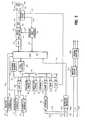
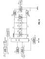
- FIGS. 3 , 4 , and 5are electrical and electrical-mechanical block diagrams of the powerpack, console and powerhead, respectively.
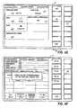
- FIGS. 6A , 6 B, 6 C, 6 D, 6 E and 6 Fare illustrations of displays produced by the console in operation of the injector.
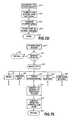
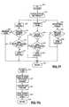
- FIGS. 7A , 7 B, 7 C, 7 D, 7 E, 7 F and 7 Gare flow charts illustrating the software operating within the power pack.
- an injection systemincludes three main components, a console 30 , a powerhead 40 and a powerpack 50 .
- the console 30comprises a liquid crystal display 32 of the type used in notebook computers (e.g., a display sold by Sharp Electronics Corp. of 5700 N.W. Pacific Rim Blvd., Camas, Wash. 98607 as part number LM64P62), coupled to an eight key keypad 34 within a housing 36 .
- display screens presented on display 32provide injection information and present the user with menus of one or more possible operations, each operation associated with one of the keys on keypad 34 .
- the powerhead 40includes a mount 42 (such as that described in the above-referenced patent application) which accepts a syringe 10 for an injection.
- the powerheadincludes a plunger drive motor (not shown) for moving plunger 12 forward into and rearward out of syringe 10 during an injection in accordance with a preprogrammed sequence, or protocol, selected by the operator by operation of the console 30 .
- the location and movement of the plunger driveis indicated by a light emitting diode (LED) which is mounted to the plunger drive and is visible to the operator through a graduated window 44 in the side of the powerhead 40 .
- LEDlight emitting diode
- this LEDflashes when the plunger drive is moving, and lights steadily when the plunger drive has been manually locked into forward or reverse motion in the manner described below.
- the side of the powerhead 40includes six pushbuttons: a start/stop button 45 , a forward manual motion button 46 , a reverse manual motion button 47 , and an enable/accelerate button 48 .
- the three enable/accelerate buttons 48perform the same function; there are three buttons instead of one to improve operator accessibility.
- the start/stop button 45is used to start an injection protocol selected at the console, or to stop and restart an injection. During an injection, all of the eight buttons on the keypad 34 of the console 30 will perform an identical start and stop function. Furthermore, a remote handswitch (not shown) may be connected to the powerpack 50 (see below) to perform a start and stop function. (For this reason, the start/stop button 45 includes a picture of a handswitch.)
- the operatorTo manually move the plunger drive, the operator must simultaneously press a motion button 46 or 47 and an enable button 48 . This is a safety feature which reduces the risk of accidental movement of the plunger. If the operator presses the forward button 46 and any of the three enable buttons 48 , the plunger will begin forward motion; conversely, if the operator presses the reverse button 47 and any of the three enable buttons 48 , the plunger will begin reverse motion. Once motion is initiated in either direction, the operator may release one of the buttons; motion will be maintained at a constant velocity in the same direction so long as any one of the five buttons 46 , 47 or 48 is held down.
- the plunger drive controller(described in more detail below) will enter a locked mode. In this locked mode, movement will continue at the maximum velocity in the same direction even if the operator releases all of the buttons. This frees the operator to perform other tasks when preparing for an injection without being forced to hold manual buttons on the injector until the plunger drive has made the lengthy transition to its fully-advanced or fully-retracted position.
- the locked modecan be terminated readily. If the operator has entered the locked mode and thereafter released all of the buttons, if at any time thereafter any of the buttons is pressed, the plunger drive controller will exit the locked mode and terminate motion.
- Light 49 Ais an injecting/fault indicator. This light glows while an injection is in process. It will flash if an error is detected.
- Light 49 Bis an enabled indicator. It glows when the injector has been enabled and is ready to perform an injection protocol.
- the rear end of the powerhead 40(opposite mount 42 ) includes a jog wheel or switch (not shown in FIG. 2B , see 163 , FIG. 5 ) used, in the manner described below, to manually activate motion of the plunger drive.
- the powerpack 50 illustrated in FIG. 2Ccontains electronics which communicate with the console 30 and powerhead 40 to perform the functions described above.
- the powerpackis connected to the console 30 and powerhead 40 by standard computer communications cables (not shown). Signals carried on these cables are interfaced to circuitry inside of the powerhead, console, and powerpack in a manner described below.
- the circuitry in the powerpackincludes a central processing unit (CPU) 52 which controls the operations of the powerhead 40 and console 30 .
- the CPUis preferably a programmable microprocessor such as the MC68332FN microprocessor, manufactured by Motorola, 2110 East Elliot, Tempe, Ariz. 85284.
- This microprocessoris a member of the 68000 family of microprocessors and features multitasking support; it is designed for use in so called “embedded” environments such as the circuit described herein, and therefore has more than the usual number direct-wired input-output ports.
- the CPUconnects to an address bus 54 for addressing a number of memory and communications components and a data bus 56 for retrieving and/or sending data from and to these components.
- Buffers 55 and 57aid CPU 52 in interfacing to the address and data busses, respectively.
- An erasable programmable read-only memory (EPROM) 58 connected to data bus 56contains the program software which operates the CPU 52 .
- the EPROMcontains an operating system, which performs low-level management of the CPU and its communications with other circuits, and a custom program for controlling the console and powerhead to perform injection protocols.
- the operating system softwareis the USX68K operating system, a multi-tasking operating system for 68000 series microprocessors sold by U.S. Software of 14215 N.W. Science Park Drive, Portland, Oreg., 97229, and the custom program is written in the “C” programming language. This custom program is described below, and a copy of the “C” language source code for the custom program appears in the appendix to this application.
- a second EPROM 60 connected to data bus 56contains language information used by the program software in EPROM 56 when generating displays for presentation on the display 32 ( FIG. 2A ).
- the display screens presented on the display 32include textual descriptions of actions being taken by the injector, and menu selections which the operator can select.
- the textual portions of these display elementsare stored in the language EPROM 56 , from which they are retrieved and inserted into a template as CPU 52 is producing a display screen.
- the language EPROMcontains multiple versions of each textual insert, representing different languages, so that the operator can, through menu choices entered at the console keypad 34 , choose a preferred language in which to generate screen displays.
- An exemplary set of languages suitable for the North American and European marketswould be English, German, French and Spanish.
- a third, electrically erasable and programmable read only memory (EEPROM) 62is attached to the data bus.
- EEPROM 62stores data in a non-volatile manner (so that it will not be lost when the power is turned off).
- EEPROM 62stores preprogrammed injection protocols. These protocols are created and stored by the user as desired (details are reviewed with reference to FIG. 6A , below).
- EEPROM 62stores calibration information, used by CPU 52 in interpreting fluid pressure and plunger position information which it receives while performing an injection. Further, EEPROM 62 stores information on the most recently completed injection, such as the injection time and volume, so that this information may be retrieved by the operator.
- EEPROM 62also stores operator preference data entered by the operator into the console (see FIG. 6E , below). This includes the preferred display language, time, and date formats. Moreover, EEPROM 62 stores operating parameters such as a programmable pressure limit, and a flag (used in the manner described below) indicating whether the injector will be used with partially pre-filled syringes of the kind illustrated in FIG. 1B . Finally, EEPROM 62 stores the registered name and/or number of the machine owner, to facilitate service and on-line customer support.
- Data bus 56is also connected to a random access memory (RAM) 64 which is used by the operating system to store a stack of register values generated during CPU operations and machine state information corresponding to currently inactive processes running on the CPU.
- RAMrandom access memory
- the application softwareuses the remaining space in RAM 64 (as managed and allocated by the operating system) to store variables computed and manipulated during operation of the injector.
- UARTsuniversal asynchronous receiver/transmitters
- a UARTis a communications circuit, generally available in integrated circuit form, which collects and buffers incoming and outgoing information to enable asynchronous communications between processors or computing systems over a data link.
- a suitable UARTis the MC68681, sold by Motorola.
- the first UART 66is responsible for communications with the powerhead circuitry (see FIG. 5 , below), which pass through an interface 70 and a communications cable 71 connected to the powerhead. (However, pulses from the optical encoder 166 on the powerhead ( FIG.
- UART 66also handles communications with an auxiliary interface 72 , which can be coupled through a communications cable 73 to a printer to allow CPU 52 to print records of an injection.
- auxiliary interface 72can be used to attach CPU 52 to a remote computer or other external device to allow remote monitoring and/or control of the injector.
- the second UART 68is responsible for communication with the console 30 ( FIG. 2A ).
- Two consoles 30can be connected to the powerpack via cables 75 , 76 .
- Cables 75 and 76carry data representing keystrokes and screen activity between the powerpack 50 and console 30 .
- This datais encoded in a communications protocol and transmitted in accordance with the RS422 standard.
- the encoded datais carried via lines 75 and 76 to interface 74 which encodes and decodes transmissions for a second UART 68 .
- UART 68routes keystrokes received by either console via interface 74 to CPU 52 via the data bus 56 , and further routes display information produced by CPU 52 to interface 74 for transmission to the consoles via lines 75 A and 76 A.
- Cables 75 and 76also include, on separate conductors, lines 75 B and 76 B, which carry logical signals corresponding to key 38 ( FIG. 2A ) of each console keyboard.
- key 38is the most frequently used key—depending on the screen being displayed, key 38 will function as an “Exit” key to depart the screen, an “Enter” key to accept a value or selection and depart the screen, or a “Disable” or “Cancel” key to terminate an operation.
- key 38is the most frequently used key, and because key 38 is used for time-sensitive input such as a cancel command, key 38 is connected to the CPU 52 differently than the other keys. Key 38 is connected directly to the CPU 52 via an interrupt line 79 ; when a keystroke is detected, a non-maskable interrupt interface (NMI) 78 (which essentially constitutes a RS422 transmitter and receiver which converts the signal on lines 75 B and 76 B to a clean logic signal on line 79 ) sets an interrupt on line 79 , which is immediately detected and subsequently serviced by CPU 52 .
- NMInon-maskable interrupt interface
- a similar interfaceis used for the remote handswitch.
- the cable 81 leading from the handswitchconnects to the handswitch interface circuit 80 which among other things, electrically isolates the handswitch from the powerpack ground, and “de-bounces” the handswitch (eliminates electrical noise created when the switch is pressed or released) so as to provide a clean logic signal indicating whether the handswitch button is being pressed or is released.
- This logic signalis connected, via line 82 , to a time processor unit (TPU) port on CPU 52 .
- CPU 52reads the logic signal at this TPU port and responds appropriately according to the software in EPROM 58 .
- A/Danalog to digital converter
- This converteris used to generate a digital signal, readable through data bus 56 , which corresponds to an analog signal received on line 85 .
- a suitable A/D converteris the LT1094, sold by Linear Technology of 1630 McCarthy Blvd., Milpitas, Calif. 95035.
- A/D converter 84is used by the motor servo control circuitry described below.
- the CPUhas two additional interfaces to the motor servo control circuitry: an interface on line 87 to a digital to analog converter (D/A) 86 (which generates an analog signal on line 88 corresponding to a digital signal received on line 87 , for example the AD7245, sold by Analog Devices of One Technology Way, P.O. Box 9106, Norwood, Mass. 02062), and a second interface on line 90 to pressure limit control circuit 92 .
- D/Adigital to analog converter
- These interfaces(lines 87 and 90 ) connect to synchronous peripheral interface (SPI) channels on the microprocessor, and are controlled in accordance with the software in EPROM 58 .
- SPIsynchronous peripheral interface
- the D/A 86 , A/D 84 , servo control 94 , pressure limit control 92 , and pressure sense 96 circuitscollectively form a motor servo control circuit which controls the operation of the motor 98 which drives the syringe plunger into and out of the syringe.
- Motor 98is shown for clarity, but it should be understood that motor 98 is physically located in the powerhead 40 ( FIG. 2B , 5 ); lines 91 and 93 connect to the motor through several conductors of the computer interface cable connecting the powerhead 40 and the powerpack.
- Servo control circuit 94responds to an analog voltage produced by D/A 86 on line 88 and produces a corresponding voltage between lines 99 and 100 .
- the voltage on lines 99 and 100is transformed by transformer 102 to a level sufficient to drive motor 98 via lines 91 and 93 .
- Servo control circuit 94contains a flyback transformer circuit which produces an output voltage related to the duty cycle of a switching FET.
- This duty cycleis produced by a UC3525 pulse width modulation (PWM) circuit—an integrated circuit which produces a 100 kHz digital output signal having a duty cycle which varies from 0% to 50% in response to an analog input voltage on line 88 .
- PWMpulse width modulation
- a suitable PWM circuitis the UC3525, sold by Unitrode of 7 Continental Boulevard, Merrimack, N.H.
- CPU 52controls the speed and power output of motor 98 by writing a digital word representing a desired output voltage to D/A 86 via lines 87 ; this digital word is then converted to an analog signal, and the analog signal is converted to a pulse width modulated control signal in the servo control, resulting in the desired output voltage at the motor.
- Pressure sense circuit 96includes a current sense circuit of which detects the current flow through line 93 (i.e., through the motor) and produces analog signals on lines 104 and 85 proportional to the detected current.
- this current sense circuitcomprises a low-value, high power rating resistor in series with line 93 which is attached to the motor 98 .
- a differential voltage amplifier(based on a low-noise, high common mode rejection op-amp) senses the voltage across the resistor and converts it to an analog voltage on lines 85 and 104 .
- the current flow through the motoris proportional to the force exerted by the motor and therefore to the injection pressure.
- the analog signals produced by pressure sense circuit 96can be used to derive the injection pressure.
- Pressure limit control circuit 92uses the analog signal on line 104 to perform a hardware pressure control function.
- Pressure limit control circuit 92contains a commercially available digital potentiometer, used to produce an analog comparison voltage.
- a suitable potentiometeris the DS1267, sold by Dallas Semiconductor of 4350 Beltwood Parkway South, Dallas, Tex. 75244.
- CPU 52(via lines 90 ) programs this potentiometer to produce a comparison voltage corresponding to the maximum allowable pressure.
- Pressure limit control circuit 92includes a comparator which compares the analog signal on line 104 produced by pressure sense circuit 96 to the comparison voltage.
- CPU 52obtains feedback on an ongoing injection from three sources: (1) feedback on the injection pressure is obtained from A/D 84 , which produces a digital word on bus 56 corresponding to the analog voltage on line 85 produced by pressure sense circuit 96 ; (2) feedback on the motor speed is obtained from an optical encoder 166 physically coupled to the motor inside of the powerhead 40 (elaborated with reference to FIG. 5 , below); and (3) feedback on the position of the plunger inside of the syringe is obtained from a linear potentiometer 168 physically coupled to the plunger (see FIG. 5 , below). Using this information, CPU 52 carefully controls the injection pressure, volume and speed according to a pre-programmed protocol under control of software in EPROM 58 .
- Power for the powerpack, powerhead, and console displayis supplied by the AC power lines 107 and 108 .
- the AC line voltageis conditioned by a conventional power supply circuit 106 which includes a transformer which can be adjusted for use with non-United States line voltages, and a voltage sense circuit for selecting the appropriate transformer based on the detected line voltage.
- the powermay be turned off by unplugging the injector, or preferably by a toggle switch which opens and closes a solid-state relay in remote on/off circuit 110 .
- the console circuitryis also built around a general purpose CPU 120 .
- a suitable microprocessoris the MC68332FN.
- the address bus 122 and data bus 124 connected to CPU 120connect to a number of supporting circuits.
- Program ROM 126contains the software which directs CPU 120 . (This software is written in assembly language, and is included in the attached appendix). Font ROM 128 includes font information retrieved by CPU 120 in producing fonts for text generated on the display screen. These fonts include foreign-language characters where necessary to support foreign language text.
- RAM 130is used by microprocessor in performing display and retrieval operations. Battery-backed RAM 132 stores the current time of day, so that the powerpack may make a date and time-stamped record of an injection.
- the primary function of the console circuitryis to generate screens on the display 32 , and to receive keystrokes from the eight-key keypad 34 ( FIG. 2A ) and relay the keystrokes to the powerpack.
- Displaysare generated by a display controller 134 , such as the F82C455 VGA controller sold by Chips & Technologies of 3050 Zanker Road, San Jose, Calif. 95134.
- This VGA controllerinteracts with CPU 120 via an address buffer 136 and data buffer 138 , and stores screen information in a dynamic random access memory (DRAM) 140 .
- Informationis sent over lines 142 to the display 32 .
- Keystrokes from the keypadare received by keyboard interface circuit 144 which “debounces” the keystrokes, producing clean logic signals on lines 146 . These logic signals are fed back to CPU 120 so that it may confirm keystrokes by producing an audible tone through speaker control circuit 150 . Speaker control circuit also generates unique audible signals to indicate other operations, such as the initiation of an injection, or to notify the operator that scanning should begin.
- a suitable controlleris the MC3487, sold by Motorola.
- CPU 120communicates with the powerpack via an RS-422 interface circuit 148 which sends and receives digital signals over lines 75 and 76 .
- Interface circuit 148also receives and forwards keystrokes directly from keyboard interface 144 .
- the eight keys on the consoleform a single, eight bit byte of information (where each bit indicates whether the key is pressed or released). This byte is coupled directly to CPU 120 via a “245” type logical buffer.
- +28 Volt DC poweris received from the power supplies in the powerpack via lines 152 .
- a power supply circuit 154regulates this +28 Volt DC power line into a collection of supply voltages, as needed by the various circuitry in the console.
- a power inverter circuitconverts +12 Volt DC power produced by the power supply circuit 154 into low-current 600 Volt AC power supplies for energizing the liquid crystal display.
- the powerheadalso includes a circuit board 160 including microprocessor to perform communications with the powerpack 50 ( FIG. 2C ).
- a suitable microprocessoris the 68HC11E2, sold by Motorola, which is a low-cost, minimal functionality microprocessor in the 68000 family.
- the circuit boardreceives and forwards keystrokes from the buttons on the keyboard 162 (described above), and electrical pulses indicating movements from the manual knob 163 mounted on the rear of the powerhead.
- a suitable manual knobis the model 600 thumbwheel, sold by Clarostat of 1 Washington Street, Dover, N.H. 03820.
- the circuit boardalso lights and extinguishes the injecting/fault indicator light 49 A and the enabled indicator light 49 B.
- the motor 98is coupled to a gear box which translates rotary motion of the motor to linear translation of the plunger.
- One suitable motoris the CYMS A2774-2 motor, sold by Barber-Colman, P.O. Box 7040, Rockford, Ill. 61125.
- the rotation of the motoris detected by optical encoder 166 (encoder 166 essentially comprises a pinwheel which rotates between a light source and a light detector to produce electrical pulses, for example the HEDS-9100 encoder, sold by Hewlett-Packard of 3003 Scott Boulevard, Santa Clara, Calif. 95054).
- Encoder 166sends electrical pulses to circuit board 160 , which relays them to powerpack 50 , allowing CPU 52 on the powerpack to monitor movement of the motor.
- the position of the plungeris detected by a linear potentiometer 168 , for example the LCPL200, sold by ETI Systems of 215 Via Del Norte, Oceanside, Calif. 92054.
- the wiper 169 of potentiometer 168is mechanically coupled to and moves with the plunger 12 .
- a DC voltage dropis placed across the potentiometer terminals 170 and 171 , and as a result, an analog voltage representative of the location of the plunger and wiper 169 is produced at the wiper 169 .
- An A/D converter on circuit board 160converts this analog voltage to a digital signal which circuit board 160 forwards to the powerpack 50 .
- Circuit board 160also detects the output of two Hall effect sensors 172 and 174 .
- the powerheadhas a removable face plate 42 ( FIG. 2B ).
- Sensor 172detects whether face plate 42 is open, and if so circuit board 160 sends a message to powerpack 50 which prevents any further injection procedures until the face plate is closed.
- Sensor 174detects the size of the face plate in use.
- circuit boardcan determine which face plate has been installed by determining whether sensor 174 has been triggered. This information is also forwarded to CPU 52 in the powerpack so that CPU 52 may compensate for the different syringe sizes when controlling motor 98 (as described below).
- circuit board 160also controls heater blanket 176 , which heats the contrast fluid in the syringe. Furthermore, circuit board 160 controls movement indicator board 178 . Movement indicator board 178 is mechanically coupled to the plunger 12 and includes two light emitting diodes LEDs 179 which are visible through window 44 on the powerhead ( FIG. 2B ). LEDs 179 provide the operator with feedback on the position of the plunger, by correlating the position of the diodes with the graduated scale on window 41 . The two sides of the window 41 contain different graduated scales: one calibrated for large syringes and one for small syringes. Depending on the syringe size detected by sensor 174 , the LED next to the appropriate graduated scale is illuminated.
- CPU 52when the plunger is moving, CPU 52 directs circuit board 160 to flash the LED. Also, when the CPU 52 enters its “locked mode” (discussed above), CPU 52 directs circuit board 160 to steadily light the LED. Thus, LEDs 179 provide operator feedback on the plunger position, direction of motion, and the “locked mode”.
- FIGS. 6A-6Fan injection protocol will be described from the operator's perspective.
- the main operating screenis illustrated in FIG. 6A .
- Box 200which is associated with an iconic representation 201 of the powerhead, identifies the current volume of contrast media in the syringe.
- Box 202which is associated with an iconic representation 203 of the syringe, identifies the total volume which has been dispensed during the currently selected protocol.
- Box 204identifies the pressure limit pre-selected by the operator for the procedure, and box 206 identifies a scan delay (in seconds), which is the delay from the time the operator initiates an injection (either with the handswitch, a key on the console or a button on the powerhead) until the x ray or magnetic scan of the subject should begin (at the end of this delay, CPU 120 produces a tone indicating to the operator that scanning should begin; alternatively, scanning could be automatically initiated by a suitable electrical connection between the scanner and injector).
- the syringecontains 180 ml of fluid, 30 ml of which will be used by the currently selected protocol, the pressure limit is 200 psi and there is no scan delay.
- Region 208identifies protocols which the operator may select, and region 210 gives details of the currently selected protocol.
- a protocolcomprises a number of phases; during each phase the injector produces a pre-programmed flow rate to output a pre-programmed total fluid volume.
- the illustrated protocol “SERIO VASCUL”has only one phase; however, other protocols which can be selected by the operator have multiple phases.
- protocolsare identified by name and by number of phases; thus, as illustrated, the “LIVER” protocol has 2 phases and the “ABDOMEN PI” protocol has 3 phases.
- the usercan select protocols, enable an injection, and otherwise navigate through display screens by pressing the buttons on the keypad 34 next to the display.
- Region 212 of the displayis dedicated to identifying the functions available from the buttons on the keypad 34 .
- the usermay select the previous or next protocol in the list in region 208 by pressing the buttons next to the words “PREVIOUS PROTOCOL” and “NEXT PROTOCOL”, respectively, on the display.
- the usermay also change and store the flow, volume and inject delay values for the current protocol by pressing the button next to “CHANGE VALUES”; doing so will alter the function of the keypad and region 212 of the display, so that the operator may select a value, increment and decrement the value, select characters to form or edit a protocol name, and then return to the display shown in FIG. 6A .
- the operatormay also enter a control panel display (see FIG. 6E , below) to adjust operating parameters and other data.
- the operatormay enter a protocol manager in which the operator may rename or delete protocols, and may determine the order of the protocol list shown in region 208 .
- the usermay also enable an injection from the display illustrated in FIG. 6A by pressing the button next to “ENABLE”.
- the injectorwhen the user enables an injection, as a safety measure, the injector first presents a text box 214 which asks the operator whether all of the air has been evacuated from the syringe.
- Region 212 of the displaycontains only the words “YES” and “NO”, indicating that the operator must answer the question as either yes or no. If the button next to “NO” is pressed, the injection will be cancelled. If the answer is “YES”, the injector will proceed to an enabled state, illustrated in FIG. 6C .
- region 208 of the displayindicates the expected duration, and region 212 includes the word “START”, “AUTO ENABLE” and “EXIT”.
- the injectorwill return to the state illustrated by FIG. 6A . If the operator presses the button next to “AUTO ENABLE”, the injector will toggle into and out of the auto-enabled mode, as confirmed by a briefly-displayed box in the center of the screen. If the operator presses the button next to “START” the injection will begin and the injector will move to the state illustrated by FIG. 6D .
- region 208indicates the total injection time and the volume (in ml) delivered to the patient.
- Region 212shows the word “STOP” next to each of the buttons on the keypad 34 , indicating that the operator may stop the injection by pressing any of the buttons (or by pressing the start/stop button 45 on the powerhead, or by pressing the handswitch).
- the total volume of fluid in the syringecounts down as fluid in injected into the subject.
- the injectorAfter the injection protocol has completed, the injector will return either to the state illustrated by FIG. 6A or to the state illustrated by FIG. 6C . If the operator put the injector in the auto-enable mode by pressing “AUTO ENABLE” at FIG. 6C , the injector will return to the state illustrated by FIG. 6C . However, if the operator did not put the injector into the auto-enable mode, the injector will return to the state illustrated by FIG. 6A . Thus, by placing the injector in auto-enable mode, the operator can more easily repeat an injection protocol; this can be useful where, for example, the contrast media dissipates relatively rapidly, and multiple images will be taken on the same area of the subject. By using “AUTO ENABLE”, the operator may replenish the contrast media just before each image by pressing a single key (or the handswitch), without re-enabling the injector.
- prefilled syringesoften include extenders which reduce the filled volume of the syringe (syringes of this type are known as “partial pre-filled” syringes).
- the injector described hereinincludes a feature for compensating for the reduced volume of partial pre-filled syringes, described below.
- the operatormay enter the “Control Panel”, illustrated in FIG. 6E .
- the displayidentifies the current operational settings of the injector.
- the control panelincludes a box 220 which identifies the current pressure limit, a box 222 which identifies the current language (as noted above, the operator may choose a language for the textual portions of the display), boxes 226 and 228 which identify the current time and date, and a box 230 which identifies the owners registration name and/or number. This information is entered using the keypad and region 212 of the display in the manner discussed above.
- Box 232on the “Control Panel” display is used to indicate whether partial pre-filled syringes will be used with the injector. Box 232 will include the word “YES” or “NO”, as selected by the operator (as shown in FIG. 6E , when the user attempts to modify this box, region 212 of the display provides a menu with the choices “YES” or “NO”).
- box 232If the operator has modified box 232 to indicate that partial pre-filled may be used (i.e., box 232 has a “YES”), then the enable procedure described above is modified slightly. If partial pre-filleds may be used, after the operator enables an injection by pressing “ENABLE” at the display of FIG. 6A , the injector presents the screen illustrated in FIG. 6F , in which the operator must identify the pre-filled syringe size by pressing a button next to “50 ml”, “65 ml”, “75 ml”, “100 ml”, or “125 ml”. Once the operator has identified the pre-filled syringe size, the injector will continue to the display illustrated in FIG. 6B .
- CPU 52FIG. 3
- the program operating in CPU 52is initiated 240 when the power is turned on.
- the programfirst initializes 242 the hardware and software attached in powerpack 50 , powerhead 40 and display 30 .
- CPU 52performs 244 diagnostics to ensure that the injector is operating properly; essentially, this involves sending test data to various hardware elements and verifying that the appropriate responses are received.
- CPU 52initiates a number of “threads”, or parallel processes; thereafter, these processes are time-multiplexed on CPU 52 under control of the above-described USX68K operating system.
- These threadscommunicate with the operating system and with each other by “messages” or semaphores—essentially, interprocess communications are placed in a globally accessible area, managed by the operating system, where they can be later retrieved by other threads.
- the operating systemallocates processing time to the threads. Much of the time, a thread will be “inactive”, i.e., it will not have any pending operations to perform.
- the threadsare generally written so that, if the thread is inactive, it will notify the operating system of this fact (“return time” to the operating system) so that the operating system can reallocate processing time to another thread.
- the operating systemallocates processing time to threads in a prioritized, round-robin fashion.
- the operating systemwill provide processing time to each thread generally in turn; if an active, low-priority thread uses more than a maximum amount of processing time, the operating system will interrupt the thread, and provide other, higher priority threads with an opportunity to use processing time.
- a high-priority threadwill not be interrupted by lower priority threads, regardless of whether the high-priority thread uses more than the maximum amount of processing time.
- most of the threadsare inactive, and there is no conflict between threads for processing time; however, in those occasions where there is a conflict, this prioritized system allows the most important threads to continue uninterrupted where necessary. It should be noted, however, that even the highest priority thread (servo thread 254 ) occasionally returns time to the operating system (at those moments where an interruption can be tolerated), so that other threads are able to continue their operations even while the highest priority thread is active.
- the threads operating in the CPU 52generally fall into two categories: “communicating” threads which send information into and out of the powerpack 50 , and “operating” threads which generate or process the information sent or received by the powerpack. There are two operating threads: state machine thread 246 and servo thread 254 .
- State machine thread 246directs the console 30 to produce screen displays of the type shown in FIGS. 6A-6E , and also processes button presses by the user.
- Thread 246is essentially a state machine, where each “state” corresponds to a display screen, and each operator keystroke produces a state transition.
- the software in program EPROM 58FIG. 3 ) essentially defines a state transition diagram, identifying specific states, displays associated with those states, and, for each state, the keystrokes or other activity which will cause a transition to another state.
- thread 246looks 270 for a message, for example a message from a communications thread indicating that console button was pressed, or a message from the servo thread indicating that the display should be updated to reflect recent injection activity. If no message has been received, the thread returns 272 time to the operating system. However, if a message has been received, the thread uses the software in program EPROM 58 to identify and transition 274 to the new state associated with the received keystroke or activity. In some cases, e.g. where the operator has pressed an invalid button, the new state will be the same as the old state; in other cases, the new state will be a different state.
- the state machine threadsends messages to the appropriate communication thread to modify 276 the screen to reflect the new state.
- the state machine threadmay send 278 messages to the servo thread, e.g. to notify the servo thread that the operator has pressed a button which starts a protocol.
- the state machinereturns 280 to the operating system.
- the thread sending the messageinitiates one or more global variables to indicate the kind of movement requested.
- Eight global variables(variables managed by the operating system and accessible by all threads), organized into four pairs, are used for this purpose. Each pair of variables identifies a desired new position for the plunger and a speed at which the plunger should move to that position.
- Four protocol phasescan be described by the four variable pairs, and thus may be executed in one message to the servo thread.
- the state machine threadsends 278 a message to the servo thread, it computes one or more desired ending positions and speeds from the selected protocol, and places the computed values into global variables.
- the servo thread 254when initiated by the operating system, the servo thread 254 first checks 282 for a message telling the servo to start motion of the plunger. If no message is received, the servo thread returns 284 time to the operating system. If, however, a start message has been received, the servo thread starts 286 the motor to move to the desired position indicated by a global variable at the desired speed indicated by a global variable. At this point, the servo thread enters a loop; during each iteration the loop checks 288 if the plunger has arrived at the desired position (the plunger position is determined by the powerhead receive thread 260 as illustrated in FIG.
- the loopterminates and the servo thread stops 290 the motor and returns.
- the servo threadchecks 292 if the speed of the motor is correct (the motor speed is measured by an interrupt routine illustrated in FIG. 7D , below). If the motor speed is incorrect, it is corrected 294 by adjusting the motor voltage. Once these steps are completed, the servo thread allows 296 the operating system three time slices (about 21 milliseconds) to operate other processes, after which it returns to step 288 to close the loop.
- the motor speedis measured by an interrupt routine.
- the processor in the powerhead circuit board 160causes an interrupt to travel on line 71 to CPU 52 .
- the interrupt routinecomputes 302 the time elapsed from the previous count interrupt, and from this elapsed time computes 304 the plunger speed. This speed value is stored 306 in a global variable (where it can be accessed by the servo routine), and the interrupt is done 308 .
- the powerhead receive thread 260is responsible for receiving messages from the powerhead and performing a number of tasks in response, including relaying manual movements of the plunger to the servo thread and (as noted above) relaying position measurements to the servo thread during movement of the plunger.
- the threadWhen the operating system initiates 260 the powerhead thread, the thread first checks 310 for any messages; if none have been received, the thread returns 312 time to the operating system. However, if the thread has received a message, it determines 312 what the message is and acts appropriately (this determination is illustrated for clarity as a multi-way branch, but in the code in the fiche appendix it is implemented as a series of individual tests performed on in sequence).
- the messagemay contain an error message 314 , a manual knob movement 316 , a linear potentiometer reading 318 (which are periodically generated by the powerhead), a fill button reading 320 (which is periodically generated by the powerhead), a start/stop button press 322 , or several others (multiple messages may be received at one time).
- the readingis converted 324 into an equivalent volume (using calibration readings stored in EEPROM 62 ). Then, an offset value (which compensates for the presence of the extender in a partial pre-filled syringe), is subtracted 326 from the computed volume, and the result is stored in a global variable, where it can be later accessed by the servo thread at step 288 ( FIG. 7C ).
- the offset value used in step 326is generated when the user identifies the partial pre-filled size in response to the display shown in FIG. 6F ; if partial pre-filled syringes are not used, the offset is set to a constant zero value.
- the powerhead threadfirst determines 330 which button, or buttons, are pressed.
- the threadfirst determines 334 whether the motor is at its maximum, latching speed (by reading the global variable indicating the motor speed, as produced by the interrupt routine illustrated in FIG. 7D ). If not, the thread increases 336 the motor speed in the indicated direction—by increasing the value of the global variable identifying the desired speed, setting the global variable identifying the desired location to identify the end of the syringe (and sending a start servo message to the servo thread if the motor is not already running)—and returns 338 time to the operating system. If, however, the motor has reached its latching speed, then the thread determines 340 if buttons were pressed the last time a fill button reading was processed.
- the threadstops 342 the motor (by setting the global variable indicating the desired speed to zero), and returns 338 time to the operating system.
- the threadfirst determines 346 if the motor is running (by checking the value of the global variable indicating the motor speed). If the motor is not running, then a single keystroke will not start it running, so the thread simply returns 338 to the operating system. If, however, the motor is running, then the thread determines 348 if buttons were pressed the last time a fill button reading was processed. If buttons were pressed last time, then the operator is merely trying to keep the motor running at its current speed by holding a button down; therefore, in this situation, the thread simply returns 338 to the operating system, allowing the motor to continue running.
- buttonswere not pressed last time, then the operator latched the motor at maximum speed, released the buttons, and some time later pressed a button in an attempt to stop the motor. Thus, in this situation, the thread stops 342 the motor (by setting the global variable indicating the desired speed to zero), and returns 338 time to the operating system.
- the threadsimply determines 354 if the motor is at its latching speed. If not, the thread stops 356 the motor and returns time to the operating system. Otherwise, the thread returns 338 directly, allowing the motor to continue running at the latching speed.
- manual motioncan also be created by turning the manual knob 163 ( FIG. 5 ) mounted on the rear of the powerhead.
- the powerhead CPU 160regularly reports movements of the manual knob to the powerpack CPU 52 . This report identifies the direction of rotation and the number of electrical pulses received from the knob since the last report (more pulses indicating greater speed of rotation).
- the powerhead receive threadfirst computes 340 a desired plunger speed from the number of pulses identified in the message, and computes 342 a desired end position from the number of pulses and the direction of rotation of the knob. These are then stored 344 in global variables accessible to the servo thread as described above. If the motor is not already running, the powerhead receive thread also sends a servo start message to the servo thread. Then the thread returns 346 time to the operating system.
- the manual motion knob 163may be replaced by any other control which allows velocity and direction control, for example by a button or knob which can be rotated or rocked to multiple positions corresponding to various velocities and directions of motions, or a set of buttons or knobs which allow the operator to separately select a desired velocity with one button or knob and a desired direction with another button or knob.
- a button or knobwhich can be rotated or rocked to multiple positions corresponding to various velocities and directions of motions
- a set of buttons or knobswhich allow the operator to separately select a desired velocity with one button or knob and a desired direction with another button or knob.
Landscapes
- Health & Medical Sciences (AREA)
- Vascular Medicine (AREA)
- Engineering & Computer Science (AREA)
- Anesthesiology (AREA)
- Biomedical Technology (AREA)
- Heart & Thoracic Surgery (AREA)
- Hematology (AREA)
- Life Sciences & Earth Sciences (AREA)
- Animal Behavior & Ethology (AREA)
- General Health & Medical Sciences (AREA)
- Public Health (AREA)
- Veterinary Medicine (AREA)
- Infusion, Injection, And Reservoir Apparatuses (AREA)
- Feeding And Watering For Cattle Raising And Animal Husbandry (AREA)
- Catching Or Destruction (AREA)
- Fluid-Pressure Circuits (AREA)
Abstract
Description
Claims (52)
Priority Applications (1)
| Application Number | Priority Date | Filing Date | Title |
|---|---|---|---|
| US12/052,494US7794429B2 (en) | 1993-11-24 | 2008-03-20 | Controlling plunger drives for fluid injections in animals |
Applications Claiming Priority (5)
| Application Number | Priority Date | Filing Date | Title |
|---|---|---|---|
| US15782393A | 1993-11-24 | 1993-11-24 | |
| US08/494,795US5662612A (en) | 1993-11-24 | 1995-06-26 | Controlling plunger drives for fluid injections in animals |
| US08/919,610US5928197A (en) | 1993-11-24 | 1997-08-28 | Controlling plunger drives for fluid injections in animals |
| US30763399A | 1999-05-07 | 1999-05-07 | |
| US12/052,494US7794429B2 (en) | 1993-11-24 | 2008-03-20 | Controlling plunger drives for fluid injections in animals |
Related Parent Applications (1)
| Application Number | Title | Priority Date | Filing Date |
|---|---|---|---|
| US30763399ADivision | 1993-11-24 | 1999-05-07 |
Publications (2)
| Publication Number | Publication Date |
|---|---|
| US20080167615A1 US20080167615A1 (en) | 2008-07-10 |
| US7794429B2true US7794429B2 (en) | 2010-09-14 |
Family
ID=22565427
Family Applications (5)
| Application Number | Title | Priority Date | Filing Date |
|---|---|---|---|
| US08/467,696Expired - LifetimeUS5681286A (en) | 1993-11-24 | 1995-06-06 | Controlling plunger drives for fluid injections in animals |
| US08/494,795Expired - LifetimeUS5662612A (en) | 1993-11-24 | 1995-06-26 | Controlling plunger drives for fluid injections in animals |
| US08/919,610Expired - LifetimeUS5928197A (en) | 1993-11-24 | 1997-08-28 | Controlling plunger drives for fluid injections in animals |
| US12/020,521Expired - Fee RelatedUS7824374B2 (en) | 1993-11-24 | 2008-01-26 | Controlling plunger drives for fluid injections in animals |
| US12/052,494Expired - Fee RelatedUS7794429B2 (en) | 1993-11-24 | 2008-03-20 | Controlling plunger drives for fluid injections in animals |
Family Applications Before (4)
| Application Number | Title | Priority Date | Filing Date |
|---|---|---|---|
| US08/467,696Expired - LifetimeUS5681286A (en) | 1993-11-24 | 1995-06-06 | Controlling plunger drives for fluid injections in animals |
| US08/494,795Expired - LifetimeUS5662612A (en) | 1993-11-24 | 1995-06-26 | Controlling plunger drives for fluid injections in animals |
| US08/919,610Expired - LifetimeUS5928197A (en) | 1993-11-24 | 1997-08-28 | Controlling plunger drives for fluid injections in animals |
| US12/020,521Expired - Fee RelatedUS7824374B2 (en) | 1993-11-24 | 2008-01-26 | Controlling plunger drives for fluid injections in animals |
Country Status (8)
| Country | Link |
|---|---|
| US (5) | US5681286A (en) |
| EP (2) | EP1323441B1 (en) |
| JP (6) | JP3853385B2 (en) |
| KR (2) | KR100373621B1 (en) |
| AT (2) | ATE339231T1 (en) |
| CA (1) | CA2129284C (en) |
| DE (2) | DE69434850T2 (en) |
| ES (2) | ES2202317T3 (en) |
Cited By (12)
| Publication number | Priority date | Publication date | Assignee | Title |
|---|---|---|---|---|
| US20080108941A1 (en)* | 2004-10-13 | 2008-05-08 | Mallinckrodt Inc. | Powerhead of a Power Injection System |
| US20100094203A1 (en)* | 2008-10-15 | 2010-04-15 | Kriesel Marshall S | Special purpose fluid dispenser |
| US9295778B2 (en) | 2011-12-21 | 2016-03-29 | Deka Products Limited Partnership | Syringe pump |
| US9744300B2 (en) | 2011-12-21 | 2017-08-29 | Deka Products Limited Partnership | Syringe pump and related method |
| US9789247B2 (en) | 2011-12-21 | 2017-10-17 | Deka Products Limited Partnership | Syringe pump, and related method and system |
| US10391241B2 (en) | 2010-01-22 | 2019-08-27 | Deka Products Limited Partnership | Syringe pump having a pressure sensor assembly |
| US10525195B1 (en) | 2018-11-24 | 2020-01-07 | RiteDose, LLC | Injection device |
| US10722645B2 (en) | 2011-12-21 | 2020-07-28 | Deka Products Limited Partnership | Syringe pump, and related method and system |
| US11217340B2 (en) | 2011-12-21 | 2022-01-04 | Deka Products Limited Partnership | Syringe pump having a pressure sensor assembly |
| US11872375B2 (en) | 2012-09-05 | 2024-01-16 | E3D Agricultural Cooperative Association Ltd. | Electronic auto-injection device |
| US12098738B2 (en) | 2011-12-21 | 2024-09-24 | Deka Products Limited Partnership | System, method, and apparatus for clamping |
| US12131826B2 (en) | 2011-12-21 | 2024-10-29 | Deka Products Limited Partnership | Syringe pump and related method |
Families Citing this family (277)
| Publication number | Priority date | Publication date | Assignee | Title |
|---|---|---|---|---|
| US5383858B1 (en) | 1992-08-17 | 1996-10-29 | Medrad Inc | Front-loading medical injector and syringe for use therewith |
| US6402718B1 (en) | 1992-08-17 | 2002-06-11 | Medrad, Inc. | Front-loading medical injector and syringe for use therewith |
| CA2129284C (en)* | 1993-11-24 | 1999-03-09 | Kenneth J. Niehoff | Controlling plunger drives for fluid injection in animals |
| US6221045B1 (en)* | 1995-04-20 | 2001-04-24 | Acist Medical Systems, Inc. | Angiographic injector system with automatic high/low pressure switching |
| US7267666B1 (en)* | 1995-04-20 | 2007-09-11 | Acist Medical Systems, Inc. | Angiographic injector system with multiple processor redundancy |
| US5651775A (en) | 1995-07-12 | 1997-07-29 | Walker; Richard Bradley | Medication delivery and monitoring system and methods |
| AU2551097A (en)* | 1996-03-29 | 1997-10-22 | Robert J. Ashcraft Jr. | Front-loading syringe adapter for front-loading medical injector |
| US5868710A (en)* | 1996-11-22 | 1999-02-09 | Liebel Flarsheim Company | Medical fluid injector |
| US5980573A (en)* | 1997-05-12 | 1999-11-09 | Shaffner; Richard L. | Method and apparatus for fighting infection and maintaining joint spacing in a prosthesis implant area |
| US6796964B2 (en)* | 1997-11-19 | 2004-09-28 | Eidson Associates, Inc | Automatic veterinary medicament delivery system |
| US5954697A (en)* | 1998-03-02 | 1999-09-21 | Srisathapat; Chad | Threaded nut syringe plunger for use with a medication infusion pump |
| US6743202B2 (en) | 1998-06-15 | 2004-06-01 | Medrad, Inc. | Encoding of syringe information |
| JP2002518108A (en)* | 1998-06-15 | 2002-06-25 | メドラッド インコーポレイテッド | Encoding syringe information |
| KR100301657B1 (en)* | 1998-08-14 | 2001-10-27 | 최수봉 | Control method of insulin syringe with pseudo mode |
| US6503573B1 (en)* | 1998-09-29 | 2003-01-07 | The United States Of America As Represented By The Secretary Of The Navy | Bomb annealing of thin films |
| DE19850841A1 (en)* | 1998-11-04 | 2000-05-25 | Eppendorf Geraetebau Netheler | Method for operating an electronic dosing system and dosing system for carrying out the method |
| US8177762B2 (en) | 1998-12-07 | 2012-05-15 | C. R. Bard, Inc. | Septum including at least one identifiable feature, access ports including same, and related methods |
| JP2000189515A (en)* | 1998-12-28 | 2000-07-11 | Nemoto Kyorindo:Kk | Device and method for packing liquid chemicals |
| US6196999B1 (en)* | 1999-02-05 | 2001-03-06 | Liebel-Flarsheim Company | Syringe/plunger coupling |
| US6645177B1 (en) | 1999-02-09 | 2003-11-11 | Alaris Medical Systems, Inc. | Directly engaged syringe driver system |
| US6635030B1 (en) | 1999-04-09 | 2003-10-21 | B.H.B. Llc | Contrast injector for injecting a contrast medium to generate prolonged uniform vascular enhancement |
| US6055985A (en)* | 1999-04-09 | 2000-05-02 | B.H.B., L.C. | Methods for injecting a contrast medium to generate prolonged uniform vascular enhancement |
| US6516749B1 (en) | 1999-06-18 | 2003-02-11 | Salasoft, Inc. | Apparatus for the delivery to an animal of a beneficial agent |
| WO2001008727A1 (en) | 1999-07-30 | 2001-02-08 | Medrad, Inc. | Injector systems and syringe adapters for use therewith |
| US20030216643A1 (en)* | 1999-07-30 | 2003-11-20 | Zatezalo Douglas M. | Programmable injector control |
| US6339718B1 (en)* | 1999-07-30 | 2002-01-15 | Medrad, Inc. | Programmable injector control |
| ES2162573B1 (en)* | 1999-08-04 | 2002-08-01 | Probitas Pharma Sa | ANGIOGRAPHY DEVICE FOR CO2 INJECTION. |
| IT1307266B1 (en)* | 1999-08-13 | 2001-10-30 | Cane Srl | APPARATUS FOR INFUSION OF DRUGS. |
| US6285155B1 (en) | 1999-10-29 | 2001-09-04 | Abbott Laboratories | Pseudo half-step motor drive method and apparatus |
| US6958053B1 (en) | 1999-11-24 | 2005-10-25 | Medrad, Inc. | Injector providing drive member advancement and engagement with syringe plunger, and method of connecting a syringe to an injector |
| US6652489B2 (en) | 2000-02-07 | 2003-11-25 | Medrad, Inc. | Front-loading medical injector and syringes, syringe interfaces, syringe adapters and syringe plungers for use therewith |
| US6626862B1 (en)* | 2000-04-04 | 2003-09-30 | Acist Medical Systems, Inc. | Fluid management and component detection system |
| AU6179001A (en)* | 2000-05-18 | 2001-11-26 | Dentsply Int Inc | Fluid material dispensing syringe |
| US6558352B1 (en)* | 2000-05-30 | 2003-05-06 | Verilogik, Inc. | System and method for variable dosage medicine delivery |
| US6663602B2 (en) | 2000-06-16 | 2003-12-16 | Novo Nordisk A/S | Injection device |
| AUPQ867900A0 (en) | 2000-07-10 | 2000-08-03 | Medrad, Inc. | Medical injector system |
| JP4689142B2 (en)* | 2000-07-22 | 2011-05-25 | イー−ファ フレセニウス カビ インコーポレイテッド | Liquid supply device |
| US6585700B1 (en) | 2000-10-05 | 2003-07-01 | Medrad, Inc. | Syringe, syringe plunger and attachment mechanism for front loading medical injector |
| US20050273079A1 (en)* | 2000-10-10 | 2005-12-08 | Hohlfelder Ingrid E | Fluid material dispensing syringe |
| US7462166B2 (en)* | 2000-12-11 | 2008-12-09 | Medrad, Inc. | Encoding and sensing of syringe information |
| IL156245A0 (en)* | 2000-12-22 | 2004-01-04 | Dca Design Int Ltd | Drive mechanism for an injection device |
| US7018363B2 (en) | 2001-01-18 | 2006-03-28 | Medrad, Inc. | Encoding and sensing of syringe information |
| US7044933B2 (en)* | 2001-03-01 | 2006-05-16 | Scimed Life Systems, Inc. | Fluid injection system for coronary intervention |
| JP3845857B2 (en)* | 2001-03-15 | 2006-11-15 | ニプロ株式会社 | Simple chemical injector |
| WO2002081011A1 (en)* | 2001-04-03 | 2002-10-17 | Medrad, Inc. | Encoding and sensing of syringe information |
| US6817986B2 (en)* | 2001-04-13 | 2004-11-16 | Avant Medical Corp. | Jet injector with data logging system for use in compliance and dose monitoring programs |
| WO2002082113A2 (en)* | 2001-04-30 | 2002-10-17 | Medrad, Inc. | Improved mr injector system with increased mobility and electromagnetic interference mitigation |
| GB2377176B (en)* | 2001-06-30 | 2004-10-20 | John Leyshon Maddocks | Devices for administering material |
| KR100407467B1 (en)* | 2001-07-12 | 2003-11-28 | 최수봉 | Insulin pump operated by remote-controller |
| JP4633095B2 (en)* | 2001-12-13 | 2011-02-16 | パナソニック株式会社 | Medical dosing device |
| US7553294B2 (en) | 2002-05-30 | 2009-06-30 | Medrad, Inc. | Syringe plunger sensing mechanism for a medical injector |
| US7018361B2 (en)* | 2002-06-14 | 2006-03-28 | Baxter International Inc. | Infusion pump |
| AU2011205123B2 (en)* | 2002-08-02 | 2014-05-22 | Liebel-Flarsheim Company | Injector |
| US6929619B2 (en)* | 2002-08-02 | 2005-08-16 | Liebel-Flarshiem Company | Injector |
| US9956377B2 (en) | 2002-09-20 | 2018-05-01 | Angiodynamics, Inc. | Method and apparatus for intra-aortic substance delivery to a branch vessel |
| JP4620929B2 (en)* | 2002-09-26 | 2011-01-26 | 株式会社根本杏林堂 | Chemical injection device |
| JP4198435B2 (en)* | 2002-10-15 | 2008-12-17 | 富士電機エフテック株式会社 | Electric syringe for dental anesthesia |
| JP4286019B2 (en)* | 2003-02-04 | 2009-06-24 | 株式会社根本杏林堂 | Chemical injection system |
| JP4731795B2 (en)* | 2003-02-18 | 2011-07-27 | 株式会社根本杏林堂 | Chemical injection device |
| US7232424B2 (en)* | 2003-04-29 | 2007-06-19 | Cardinal Health 303, Inc. | Syringe pump bearing mechanism |
| US7419478B1 (en) | 2003-06-25 | 2008-09-02 | Medrad, Inc. | Front-loading syringe for medical injector having a flexible syringe retaining ring |
| JP4654129B2 (en) | 2003-07-18 | 2011-03-16 | 株式会社根本杏林堂 | A chemical injection device that displays an image of the input injection conditions |
| US8422413B2 (en)* | 2003-09-18 | 2013-04-16 | Dentsply International Inc. | Process and device for the wireless transmission of dental process data |
| WO2005039675A1 (en)* | 2003-10-29 | 2005-05-06 | Nemoto Kyorindo Co., Ltd | Medicinal liquid infusion apparatus |
| JP2005131007A (en)* | 2003-10-29 | 2005-05-26 | Nemoto Kyorindo:Kk | Medical fluid injection system |
| US7666169B2 (en) | 2003-11-25 | 2010-02-23 | Medrad, Inc. | Syringe and syringe plungers for use with medical injectors |
| USD1031029S1 (en) | 2003-11-25 | 2024-06-11 | Bayer Healthcare Llc | Syringe plunger |
| US7850640B2 (en)* | 2003-11-26 | 2010-12-14 | Acist Medical Systems, Inc. | Device, method, and computer program product for dispensing media as part of a medical procedure |
| US7976793B2 (en)* | 2003-11-27 | 2011-07-12 | Gilson S.A.S. | Electronic pipette |
| US7621892B2 (en)* | 2003-12-31 | 2009-11-24 | Mallinckrodt Inc. | Contrast container holder and method to fill syringes |
| US20050148867A1 (en)* | 2003-12-31 | 2005-07-07 | Liebel-Flarsheim Company | Injector with changeable syringe constants |
| US20050177111A1 (en)* | 2004-02-06 | 2005-08-11 | Shaul Ozeri | Miniature infusion pump |
| US20050182322A1 (en)* | 2004-02-17 | 2005-08-18 | Liebel-Flarsheim Company | Injector auto purge |
| US7771389B2 (en) | 2004-02-17 | 2010-08-10 | Mallinckrodt Inc. | Injector auto purge |
| ES2385140T3 (en)* | 2004-02-18 | 2012-07-18 | Ares Trading S.A. | Portable electronic injection device for injecting liquid medications |
| EP1640029A1 (en)* | 2004-09-24 | 2006-03-29 | Novo Nordisk A/S | Injection device with cap |
| US20060079842A1 (en)* | 2004-10-13 | 2006-04-13 | Liebel-Flarsheim Company | Powerhead control in a power injection system |
| USD550838S1 (en) | 2004-10-13 | 2007-09-11 | Liebel-Flarsheim Company | Power injection system face plate |
| USD572818S1 (en) | 2004-10-13 | 2008-07-08 | Mallinckrodt, Inc. | Power injection system face plate |
| ATE444090T1 (en) | 2004-10-21 | 2009-10-15 | Novo Nordisk As | SELECTION MECHANISM FOR A ROTARY PIN |
| JP5147407B2 (en) | 2004-10-21 | 2013-02-20 | ノボ・ノルデイスク・エー/エス | Infusion device with processor for collecting release information |
| WO2006045523A1 (en)* | 2004-10-21 | 2006-05-04 | Novo Nordisk A/S | Medication delivery system with a detector for providing a signal indicative of an amount of an ejected dose of drug |
| WO2006045524A1 (en)* | 2004-10-21 | 2006-05-04 | Novo Nordisk A/S | An injection device with means for signalling the time since the last injection |
| CA2584521C (en)* | 2004-10-27 | 2014-07-29 | E-Z-Em, Inc. | Data collection device, system, method, and computer program product for collecting data related to the dispensing of contrast media |
| US20080004507A1 (en)* | 2004-10-27 | 2008-01-03 | E-Z-Em, Inc. | Data collection device, system, method, and computer program product for collecting data related to the dispensing of contrast media |
| EP1825876A4 (en)* | 2004-11-11 | 2009-09-16 | Nemoto Kyorindo Co Ltd | Chemical liquid infusion system |
| US9022980B2 (en) | 2005-02-01 | 2015-05-05 | Kaleo, Inc. | Medical injector simulation device |
| US8206360B2 (en) | 2005-02-01 | 2012-06-26 | Intelliject, Inc. | Devices, systems and methods for medicament delivery |
| AU2006210865B2 (en)* | 2005-02-01 | 2008-12-04 | Kaleo, Inc. | Devices, systems, and methods for medicament delivery |
| US7731686B2 (en)* | 2005-02-01 | 2010-06-08 | Intelliject, Inc. | Devices, systems and methods for medicament delivery |
| US8231573B2 (en) | 2005-02-01 | 2012-07-31 | Intelliject, Inc. | Medicament delivery device having an electronic circuit system |
| US8361026B2 (en) | 2005-02-01 | 2013-01-29 | Intelliject, Inc. | Apparatus and methods for self-administration of vaccines and other medicaments |
| EP1690560A1 (en)* | 2005-02-14 | 2006-08-16 | Ares Trading S.A. | Medication delivery device |
| EP1690559A1 (en)* | 2005-02-14 | 2006-08-16 | Ares Trading S.A. | Medication delivery device |
| US20100185152A1 (en)* | 2005-02-14 | 2010-07-22 | Novo Nordisk A/S | Dosing Operation In A Medical Device |
| WO2006086980A1 (en)* | 2005-02-21 | 2006-08-24 | Novo Nordisk A/S | A method for ensuring constant speed of a motor in an injection device |
| JP2008531093A (en)* | 2005-02-23 | 2008-08-14 | ノボ・ノルデイスク・エー/エス | Method and apparatus for reversing a piston rod in an injection device |
| US8029482B2 (en) | 2005-03-04 | 2011-10-04 | C. R. Bard, Inc. | Systems and methods for radiographically identifying an access port |
| JP5484674B2 (en) | 2005-03-04 | 2014-05-07 | シー・アール・バード・インコーポレーテッド | Access port and identification method |
| US7947022B2 (en)* | 2005-03-04 | 2011-05-24 | C. R. Bard, Inc. | Access port identification systems and methods |
| US9474888B2 (en) | 2005-03-04 | 2016-10-25 | C. R. Bard, Inc. | Implantable access port including a sandwiched radiopaque insert |
| EP1912135B1 (en)* | 2005-04-06 | 2010-09-15 | Mallinckrodt, Inc. | System and methods for managing information relating to medical fluids and containers therefor |
| US20090043264A1 (en) | 2005-04-24 | 2009-02-12 | Novo Nordisk A/S | Injection Device |
| EP1874393B1 (en) | 2005-04-27 | 2017-09-06 | C.R.Bard, Inc. | Infusion apparatuses |
| US10307581B2 (en) | 2005-04-27 | 2019-06-04 | C. R. Bard, Inc. | Reinforced septum for an implantable medical device |
| EP3884989B1 (en) | 2005-04-27 | 2022-07-13 | C. R. Bard, Inc. | Vascular access port |
| US20060271014A1 (en)* | 2005-05-31 | 2006-11-30 | Mallinckrodt Inc. | Heat retention device for a syringe and methods of use |
| US20070060887A1 (en)* | 2005-08-22 | 2007-03-15 | Marsh David A | Ophthalmic injector |
| US20070088269A1 (en)* | 2005-09-30 | 2007-04-19 | Sherwood Services Ag | Medical pump with lockout system |
| US7534099B2 (en) | 2005-09-30 | 2009-05-19 | Covidien Ag | Aliquot correction for feeding set degradation |
| US8275942B2 (en)* | 2005-12-22 | 2012-09-25 | Intel Corporation | Performance prioritization in multi-threaded processors |
| DE102006006952A1 (en)* | 2006-02-14 | 2007-08-23 | E-Z-Em, Inc. | MRI system |
| JP5062768B2 (en)* | 2006-03-10 | 2012-10-31 | ノボ・ノルデイスク・エー/エス | INJECTION DEVICE AND METHOD FOR REPLACING CARTRIDGE OF THE DEVICE |
| CN101400394B (en)* | 2006-03-10 | 2012-07-04 | 诺沃-诺迪斯克有限公司 | An injection device having a gearing arrangement |
| US8926569B2 (en) | 2006-03-15 | 2015-01-06 | Bayer Medical Care Inc. | Plunger covers and plungers for use in syringes and methods of fabricating plunger covers and plungers for use in syringes |
| CN101405738B (en)* | 2006-03-20 | 2011-11-23 | 诺沃-诺迪斯克有限公司 | Method and electronic module for wirelessly monitoring the operation of a mechanical drug delivery device |
| US20080033368A1 (en)* | 2006-04-04 | 2008-02-07 | Mallinckrodt Inc. | Systems and methods for managing information relating to medical fluids and containers therefor |
| CA2648283A1 (en) | 2006-04-07 | 2007-10-18 | Societe De Commercialisation Des Produits De La Recherche Appliquee Socp Ra Sciences Et Genie S.E.C. | Integrated cement delivery system for bone augmentation procedures and methods |
| US9867646B2 (en) | 2006-04-07 | 2018-01-16 | Gamal Baroud | Integrated cement delivery system for bone augmentation procedures and methods |
| ATE458517T1 (en) | 2006-05-16 | 2010-03-15 | Novo Nordisk As | TRANSMISSION MECHANISM FOR AN INJECTION DEVICE |
| US7815603B2 (en)* | 2006-05-17 | 2010-10-19 | Alcon Research, Ltd. | Ophthalmic injection method |
| US7887521B2 (en)* | 2006-05-17 | 2011-02-15 | Alcon Research, Ltd. | Ophthalmic injection system |
| US7811252B2 (en)* | 2006-05-17 | 2010-10-12 | Alcon Research, Ltd. | Dosage control device |
| JP5253387B2 (en) | 2006-05-18 | 2013-07-31 | ノボ・ノルデイスク・エー/エス | Injection device with mode locking means |
| US8118853B2 (en)* | 2006-06-19 | 2012-02-21 | Cook Medical Technologies Llc | Prosthesis delivery and deployment device |
| USD659234S1 (en)* | 2006-08-11 | 2012-05-08 | Cane S.R.L. | Drug infusion device with a protective cap |
| USD565176S1 (en)* | 2006-08-11 | 2008-03-25 | Cane' S.R.L | Protective cap for a drug infusion device |
| US8038656B2 (en) | 2006-09-29 | 2011-10-18 | Tyco Healthcare Group Lp | Detachable plunger rod syringe |
| US8052655B2 (en) | 2006-09-29 | 2011-11-08 | Novo Nordisk A/S | Injection device with electronic detecting means |
| DE102006047537B4 (en)* | 2006-10-07 | 2024-05-16 | Sanofi-Aventis Deutschland Gmbh | Method and device for determining the position of a stopper of an ampoule for a drug in a medical device and their use, a corresponding medical device and manufacture of a medical device |
| WO2008140546A2 (en)* | 2006-10-16 | 2008-11-20 | Alcon Research, Ltd. | Limited reuse assembly for ophthalmic injection device |
| KR20090091714A (en)* | 2006-10-16 | 2009-08-28 | 알콘 리서치, 리미티드 | Temperature control and thermal sensor assembly for medical devices |
| US9022970B2 (en)* | 2006-10-16 | 2015-05-05 | Alcon Research, Ltd. | Ophthalmic injection device including dosage control device |
| US20080281292A1 (en)* | 2006-10-16 | 2008-11-13 | Hickingbotham Dyson W | Retractable Injection Port |
| WO2008115270A2 (en) | 2006-10-16 | 2008-09-25 | Alcon Research, Ltd. | Ophthalmic injection device including dosage control device |
| CA2664160A1 (en)* | 2006-10-16 | 2008-09-12 | Alcon Research, Ltd. | Method of operating ophthalmic hand piece with disposable end |
| JP2010506673A (en)* | 2006-10-16 | 2010-03-04 | アルコン リサーチ, リミテッド | Universal rechargeable limited reuse assembly for ophthalmic handpieces |
| US9265912B2 (en) | 2006-11-08 | 2016-02-23 | C. R. Bard, Inc. | Indicia informative of characteristics of insertable medical devices |
| US9642986B2 (en) | 2006-11-08 | 2017-05-09 | C. R. Bard, Inc. | Resource information key for an insertable medical device |
| US8454560B2 (en)* | 2006-12-05 | 2013-06-04 | Mallinckrodt Llc | Syringe mount for a medical fluid injector |
| EP2125075A2 (en) | 2007-01-22 | 2009-12-02 | Intelliject, Inc. | Medical injector with compliance tracking and monitoring |
| USD598548S1 (en)* | 2007-02-16 | 2009-08-18 | Nuclea Biomarkers, Llc | Stylet |
| USD942005S1 (en) | 2007-03-14 | 2022-01-25 | Bayer Healthcare Llc | Orange syringe plunger cover |
| USD1002840S1 (en) | 2007-03-14 | 2023-10-24 | Bayer Healthcare Llc | Syringe plunger |
| USD847985S1 (en) | 2007-03-14 | 2019-05-07 | Bayer Healthcare Llc | Syringe plunger cover |
| BRPI0809265A2 (en) | 2007-03-23 | 2014-10-07 | Novo Nordisk As | INJECTION DEVICE INCLUDING A TIGHTENING NUT |
| US20080306443A1 (en)* | 2007-06-06 | 2008-12-11 | Mallinckrodt Inc. | Medical Fluid Injector Having Wireless Pressure Monitoring Feature |
| ES2651269T3 (en) | 2007-06-20 | 2018-01-25 | Medical Components, Inc. | Venous reservoir with molded indications and / or radiopacas |
| WO2009012385A1 (en) | 2007-07-19 | 2009-01-22 | Medical Components, Inc. | Venous access port assembly with x-ray discernable indicia |
| US9610432B2 (en) | 2007-07-19 | 2017-04-04 | Innovative Medical Devices, Llc | Venous access port assembly with X-ray discernable indicia |
| EP2187996B1 (en)* | 2007-08-13 | 2011-10-12 | Mallinckrodt LLC | Drive ram for medical injectors |
| US9108006B2 (en) | 2007-08-17 | 2015-08-18 | Novo Nordisk A/S | Medical device with value sensor |
| US8141417B2 (en)* | 2007-08-23 | 2012-03-27 | Mallinckrodt Llc | Syringe content detection using RF energy |
| JP4994167B2 (en)* | 2007-09-21 | 2012-08-08 | 富士電機エフテック株式会社 | Dental anesthesia syringe |
| US9579496B2 (en) | 2007-11-07 | 2017-02-28 | C. R. Bard, Inc. | Radiopaque and septum-based indicators for a multi-lumen implantable port |
| US9026370B2 (en) | 2007-12-18 | 2015-05-05 | Hospira, Inc. | User interface improvements for medical devices |
| CA2707820A1 (en)* | 2007-12-31 | 2009-07-09 | Novo Nordisk A/S | Electronically monitored injection device |
| WO2009091851A2 (en)* | 2008-01-18 | 2009-07-23 | Mallinckrodt Inc. | Medical fluid injector with auto-calibration based on system wear and usage |
| US8161810B2 (en) | 2008-01-29 | 2012-04-24 | Carefusion 303, Inc. | Syringe imaging systems |
| GB0808389D0 (en)* | 2008-05-09 | 2008-06-18 | Owen Mumford Ltd | Electrically actuated injector |
| US8021344B2 (en) | 2008-07-28 | 2011-09-20 | Intelliject, Inc. | Medicament delivery device configured to produce an audible output |
| USD994111S1 (en) | 2008-05-12 | 2023-08-01 | Kaleo, Inc. | Medicament delivery device cover |
| CA3070618C (en) | 2008-05-20 | 2021-07-20 | Avant Medical Corp. | Autoinjector system |
| US8052645B2 (en) | 2008-07-23 | 2011-11-08 | Avant Medical Corp. | System and method for an injection using a syringe needle |
| ES2397135T3 (en)* | 2008-08-19 | 2013-03-05 | Mallinckrodt Llc | Automatic injector with tilt sensor and syringe communication logic |
| EP2328641B1 (en)* | 2008-08-29 | 2014-12-31 | Novo Nordisk A/S | Medical injection device with time delay indicator |
| ES2906416T3 (en) | 2008-10-31 | 2022-04-18 | Bard Inc C R | Systems and methods to identify an access road |
| US11890443B2 (en) | 2008-11-13 | 2024-02-06 | C. R. Bard, Inc. | Implantable medical devices including septum-based indicators |
| US8932271B2 (en) | 2008-11-13 | 2015-01-13 | C. R. Bard, Inc. | Implantable medical devices including septum-based indicators |
| CA2722991A1 (en)* | 2008-11-28 | 2010-06-03 | Mallinckrodt Inc. | Workflow driven user interface for medical fluid delivery systems |
| CN102256644B (en)* | 2008-12-22 | 2015-04-29 | 松下健康医疗控股株式会社 | drug delivery device |
| KR101079155B1 (en)* | 2009-02-24 | 2011-11-02 | 김명섭 | Automatic Fine Needle Cell Aspirator |
| US8372036B2 (en) | 2009-05-06 | 2013-02-12 | Alcon Research, Ltd. | Multi-layer heat assembly for a drug delivery device |
| EP2451512A1 (en) | 2009-07-07 | 2012-05-16 | C.R. Bard Inc. | Extensible internal bolster for a medical device |
| EP2456572B1 (en) | 2009-07-24 | 2014-02-26 | BAYER Medical Care Inc. | Multi-fluid medical injector system |
| US8932256B2 (en)* | 2009-09-02 | 2015-01-13 | Medtronic Minimed, Inc. | Insertion device systems and methods |
| US8308679B2 (en)* | 2009-12-30 | 2012-11-13 | Medtronic Minimed, Inc. | Alignment systems and methods |
| US8900190B2 (en)* | 2009-09-02 | 2014-12-02 | Medtronic Minimed, Inc. | Insertion device systems and methods |
| WO2011054110A1 (en) | 2009-11-06 | 2011-05-12 | Socpra Sciences Et Genie S. E. C. | Bone cement delivery system |
| ES2695907T3 (en) | 2009-11-17 | 2019-01-11 | Bard Inc C R | Overmolded access port that includes anchoring and identification features |
| US8177747B2 (en) | 2009-12-22 | 2012-05-15 | Alcon Research, Ltd. | Method and apparatus for drug delivery |
| US8998858B2 (en)* | 2009-12-29 | 2015-04-07 | Medtronic Minimed, Inc. | Alignment and connection systems and methods |
| US8998840B2 (en) | 2009-12-30 | 2015-04-07 | Medtronic Minimed, Inc. | Connection and alignment systems and methods |
| US8858500B2 (en)* | 2009-12-30 | 2014-10-14 | Medtronic Minimed, Inc. | Engagement and sensing systems and methods |
| US9039653B2 (en)* | 2009-12-29 | 2015-05-26 | Medtronic Minimed, Inc. | Retention systems and methods |
| US20120215163A1 (en) | 2009-12-30 | 2012-08-23 | Medtronic Minimed, Inc. | Sensing systems and methods |
| US9421321B2 (en)* | 2009-12-30 | 2016-08-23 | Medtronic Minimed, Inc. | Connection and alignment systems and methods |
| US11497850B2 (en) | 2009-12-30 | 2022-11-15 | Medtronic Minimed, Inc. | Connection and alignment detection systems and methods |
| US8435209B2 (en) | 2009-12-30 | 2013-05-07 | Medtronic Minimed, Inc. | Connection and alignment detection systems and methods |
| CN102939120B (en) | 2010-06-04 | 2016-12-07 | 拜耳医药保健有限责任公司 | Systems and methods for planning and monitoring the use of multiple doses of radiopharmaceuticals on radiopharmaceutical syringes |
| WO2011163511A1 (en)* | 2010-06-23 | 2011-12-29 | Tcb Medical Devices, Llc | Injector for auto-injection of medication and associated method of use |
| USD676955S1 (en) | 2010-12-30 | 2013-02-26 | C. R. Bard, Inc. | Implantable access port |
| USD682416S1 (en) | 2010-12-30 | 2013-05-14 | C. R. Bard, Inc. | Implantable access port |
| US9173999B2 (en) | 2011-01-26 | 2015-11-03 | Kaleo, Inc. | Devices and methods for delivering medicaments from a multi-chamber container |
| US8627816B2 (en) | 2011-02-28 | 2014-01-14 | Intelliject, Inc. | Medicament delivery device for administration of opioid antagonists including formulations for naloxone |
| US8939943B2 (en) | 2011-01-26 | 2015-01-27 | Kaleo, Inc. | Medicament delivery device for administration of opioid antagonists including formulations for naloxone |
| WO2012127046A2 (en) | 2011-03-24 | 2012-09-27 | Sanofi-Aventis Deutschland Gmbh | Device and method for detecting an actuation action performable with a medical device |
| PL2699293T3 (en) | 2011-04-20 | 2019-08-30 | Amgen Inc. | Autoinjector apparatus |
| WO2012172818A1 (en)* | 2011-06-16 | 2012-12-20 | テルモ株式会社 | Color display circuit for liquid crystal display |
| CN106267472B (en) | 2011-07-15 | 2019-08-30 | 赛诺菲-安万特德国有限公司 | Drug delivery device with electromechanical drive mechanism |
| EP2731651B1 (en) | 2011-07-15 | 2020-03-11 | Sanofi-Aventis Deutschland GmbH | A drug delivery device |
| AU2012299169B2 (en) | 2011-08-19 | 2017-08-24 | Icu Medical, Inc. | Systems and methods for a graphical interface including a graphical representation of medical data |
| WO2013026859A1 (en)* | 2011-08-23 | 2013-02-28 | Sanofi-Aventis Deutschland Gmbh | Cartridge with adjustable filling volume |
| US10022498B2 (en) | 2011-12-16 | 2018-07-17 | Icu Medical, Inc. | System for monitoring and delivering medication to a patient and method of using the same to minimize the risks associated with automated therapy |
| JP6069351B2 (en) | 2011-12-29 | 2017-02-01 | ノボ・ノルデイスク・エー/エス | Torsion spring type automatic syringe with dial-up / dial-down administration mechanism |
| JP6306566B2 (en) | 2012-03-30 | 2018-04-04 | アイシーユー・メディカル・インコーポレーテッド | Air detection system and method for detecting air in an infusion system pump |
| USD898908S1 (en) | 2012-04-20 | 2020-10-13 | Amgen Inc. | Pharmaceutical product cassette for an injection device |
| US9522235B2 (en) | 2012-05-22 | 2016-12-20 | Kaleo, Inc. | Devices and methods for delivering medicaments from a multi-chamber container |
| JP6108270B2 (en)* | 2012-06-26 | 2017-04-05 | パナソニックIpマネジメント株式会社 | Chemical inspection device |
| AU2013296555B2 (en) | 2012-07-31 | 2017-10-19 | Icu Medical, Inc. | Patient care system for critical medications |
| US9999718B2 (en) | 2012-08-28 | 2018-06-19 | Osprey Medical, Inc. | Volume monitoring device utilizing light-based systems |
| US11219719B2 (en) | 2012-08-28 | 2022-01-11 | Osprey Medical, Inc. | Volume monitoring systems |
| US10413677B2 (en) | 2012-08-28 | 2019-09-17 | Osprey Medical, Inc. | Volume monitoring device |
| US11116892B2 (en) | 2012-08-28 | 2021-09-14 | Osprey Medical, Inc. | Medium injection diversion and measurement |
| EP2897673B1 (en) | 2012-09-24 | 2020-01-22 | Medline Industries, Inc. | Power injector device and method of use |
| JP5869684B2 (en)* | 2012-09-26 | 2016-02-24 | テルモ株式会社 | Controller for life support apparatus and control method thereof |
| US9174003B2 (en) | 2012-09-28 | 2015-11-03 | Bayer Medical Care Inc. | Quick release plunger |
| GB2526948A (en) | 2012-12-27 | 2015-12-09 | Kaleo Inc | Systems for locating and interacting with medicament delivery devices |
| US11369739B2 (en) | 2013-01-21 | 2022-06-28 | Medline Industries, Lp | Method to provide injection system parameters for injecting fluid into patient |
| CA2904661C (en) | 2013-03-15 | 2022-03-15 | Amgen Inc. | Drug cassette, autoinjector, and autoinjector system |
| AU2014268355B2 (en) | 2013-05-24 | 2018-06-14 | Icu Medical, Inc. | Multi-sensor infusion system for detecting air or an occlusion in the infusion system |
| US10166328B2 (en) | 2013-05-29 | 2019-01-01 | Icu Medical, Inc. | Infusion system which utilizes one or more sensors and additional information to make an air determination regarding the infusion system |
| WO2014194065A1 (en) | 2013-05-29 | 2014-12-04 | Hospira, Inc. | Infusion system and method of use which prevents over-saturation of an analog-to-digital converter |
| KR101448679B1 (en) | 2013-06-26 | 2014-10-08 | (주)디앤케이 | Apparatus for drug leakage protection and method thereof |
| AU2014284577A1 (en)* | 2013-07-03 | 2016-01-21 | Smiths Medical Asd, Inc. | Combination linear potentiometer and syringe thumbpress detection sensor and related systems and methods |
| US9173726B2 (en)* | 2013-07-18 | 2015-11-03 | Christopher R. Sabourin | Illuminated intra-oral delivery device |
| JP6526004B2 (en)* | 2013-08-23 | 2019-06-05 | オスプレイ メディカル インク. | Capacity monitoring device |
| US8932268B1 (en)* | 2013-09-23 | 2015-01-13 | Edward D. Struzinski | Medication cartridge injection assembly |
| ES2901783T3 (en) | 2014-01-27 | 2022-03-23 | Te Pari Products Ltd | A fluid dispenser |
| EP3110474B1 (en) | 2014-02-28 | 2019-12-18 | ICU Medical, Inc. | Infusion system and method which utilizes dual wavelength optical air-in-line detection |
| AU2015231396B2 (en) | 2014-03-19 | 2018-12-06 | Bayer Healthcare Llc | System for syringe engagement to an injector |
| US11344673B2 (en) | 2014-05-29 | 2022-05-31 | Icu Medical, Inc. | Infusion system and pump with configurable closed loop delivery rate catch-up |
| WO2015200543A2 (en)* | 2014-06-24 | 2015-12-30 | The University Of Toledo | Apparatus and method for injecting bone graft substitute and other materials |
| US9517307B2 (en) | 2014-07-18 | 2016-12-13 | Kaleo, Inc. | Devices and methods for delivering opioid antagonists including formulations for naloxone |
| US11344668B2 (en) | 2014-12-19 | 2022-05-31 | Icu Medical, Inc. | Infusion system with concurrent TPN/insulin infusion |
| EP3058970A1 (en) | 2015-02-19 | 2016-08-24 | Sanofi-Aventis Deutschland GmbH | Data collection device for attachment to an injection device |
| US10850024B2 (en) | 2015-03-02 | 2020-12-01 | Icu Medical, Inc. | Infusion system, device, and method having advanced infusion features |
| US10695495B2 (en) | 2015-03-24 | 2020-06-30 | Kaleo, Inc. | Devices and methods for delivering a lyophilized medicament |
| JP6815650B2 (en)* | 2015-04-16 | 2021-01-20 | 株式会社根本杏林堂 | Chemical injection device, control method of chemical injection device, computer program |
| CN113456946B (en) | 2015-06-09 | 2023-12-26 | 赛诺菲-安万特德国有限公司 | Data acquisition device for attachment to an injection device |
| DK3341048T3 (en) | 2015-08-28 | 2023-08-21 | Bayer Healthcare Llc | SYSTEM AND METHOD FOR VERIFYING INJECTION FLUID FILLING AND IMAGE RECOGNITION OF POWER INJECTOR SYSTEM TRAITS |
| US9480797B1 (en) | 2015-10-28 | 2016-11-01 | Bayer Healthcare Llc | System and method for syringe plunger engagement with an injector |
| CN105771038B (en)* | 2016-03-17 | 2022-09-13 | 南京医科大学第一附属医院 | Accurate trace acupuncture point injection pen |
| CN109069764B (en) | 2016-03-28 | 2021-05-11 | 麦瑞通医疗设备有限公司 | Inflator with removable housing and related method |
| CA3023658C (en) | 2016-05-13 | 2023-03-07 | Icu Medical, Inc. | Infusion pump system and method with common line auto flush |
| WO2017214441A1 (en) | 2016-06-10 | 2017-12-14 | Icu Medical, Inc. | Acoustic flow sensor for continuous medication flow measurements and feedback control of infusion |
| EP3481462B1 (en) | 2016-07-06 | 2021-03-24 | Bayer Healthcare LLC | Contrast heating system with in-line contrast warmer |
| US10532166B2 (en) | 2016-07-08 | 2020-01-14 | Bayer Heatlhcare Llc | System and method for identifying a fill volume of a fluid chamber |
| EP3858395A1 (en)* | 2016-12-01 | 2021-08-04 | Fenwal, Inc. | Fill and finish systems and methods |
| HUE063479T2 (en) | 2017-01-06 | 2024-01-28 | Bayer Healthcare Llc | Syringe plunger with dynamic seal |
| CA3046354A1 (en) | 2017-01-17 | 2018-07-26 | Kaleo, Inc. | Medicament delivery devices with wireless connectivity and event detection |
| EP3961641A1 (en) | 2017-01-24 | 2022-03-02 | Bayer Healthcare LLC | Injector systems and syringe adapters for use therewith |
| CA3050752C (en) | 2017-02-28 | 2022-09-06 | Eli Lilly And Company | Dose detection and drug identification for a medication delivery device |
| WO2019046261A1 (en)* | 2017-08-31 | 2019-03-07 | Bayer Healthcare Llc | System and method for drive member position and fluid injector system mechanical calibration |
| US10089055B1 (en) | 2017-12-27 | 2018-10-02 | Icu Medical, Inc. | Synchronized display of screen content on networked devices |
| US11246625B2 (en) | 2018-01-19 | 2022-02-15 | Boston Scientific Scimed, Inc. | Medical device delivery system with feedback loop |
| US11071831B2 (en) | 2018-02-22 | 2021-07-27 | Eli Lilly And Company | Dose detection system module for medication delivery device |
| HUE061426T2 (en) | 2018-02-27 | 2023-06-28 | Bayer Healthcare Llc | Syringe piston switch mechanism |
| DE102018108203A1 (en) | 2018-04-06 | 2019-10-10 | Fresenius Medical Care Deutschland Gmbh | Method for calibrating a syringe pump, syringe pump and devices |
| EP3593838A1 (en)* | 2018-07-13 | 2020-01-15 | Zyno Medical, Llc | High precision syringe with removable pump unit |
| US11679205B2 (en) | 2018-07-13 | 2023-06-20 | Zyno Medical Llc | High precision syringe with removable pump unit |
| US11929160B2 (en) | 2018-07-16 | 2024-03-12 | Kaleo, Inc. | Medicament delivery devices with wireless connectivity and compliance detection |
| WO2020210623A1 (en) | 2019-04-12 | 2020-10-15 | Osprey Medical Inc. | Energy-efficient position determining with multiple sensors |
| US20220296811A1 (en)* | 2019-07-26 | 2022-09-22 | Shenzhen Mindray Scientific Co., Ltd. | Injection pump and infusion pump |
| US20220323672A1 (en)* | 2019-09-02 | 2022-10-13 | Nemera La Verpillière | System and device for dispensing a product |
| CN110731831A (en)* | 2019-09-27 | 2020-01-31 | 卢维红 | Intelligent veterinary automatic injector |
| WO2021094388A1 (en)* | 2019-11-14 | 2021-05-20 | Sanofi | A wireless data communication accessory for a drug delivery device |
| US11278671B2 (en) | 2019-12-04 | 2022-03-22 | Icu Medical, Inc. | Infusion pump with safety sequence keypad |
| BR112022023788A2 (en) | 2020-06-18 | 2022-12-27 | Bayer Healthcare Llc | SYSTEM AND METHOD OF COUPLING A SYRINGE PLUNGER WITH AN INJECTOR |
| CA3189781A1 (en) | 2020-07-21 | 2022-01-27 | Icu Medical, Inc. | Fluid transfer devices and methods of use |
| US11559823B2 (en)* | 2020-09-18 | 2023-01-24 | Asmpt Singapore Pte. Ltd. | Volumetric measurement and regulation device incorporated in a time-pressure dispenser |
| CN112206069B (en)* | 2020-10-12 | 2023-06-02 | 北京天悦生科技有限公司 | Continuous injector control method and device and continuous injector |
| US11135360B1 (en) | 2020-12-07 | 2021-10-05 | Icu Medical, Inc. | Concurrent infusion with common line auto flush |
| CN112827017B (en)* | 2021-01-04 | 2023-03-14 | 杨爱华 | Novel accurate intelligent anaesthetic injection device and use method thereof |
| USD1091564S1 (en) | 2021-10-13 | 2025-09-02 | Icu Medical, Inc. | Display screen or portion thereof with graphical user interface for a medical device |
| CA3241894A1 (en) | 2021-12-10 | 2023-06-15 | Icu Medical, Inc. | Medical fluid compounding systems with coordinated flow control |
| WO2025090056A1 (en)* | 2023-10-23 | 2025-05-01 | Carefusion 303, Inc. | System and method for mixing multiple medications |
Citations (37)
| Publication number | Priority date | Publication date | Assignee | Title |
|---|---|---|---|---|
| US2702547A (en) | 1950-02-27 | 1955-02-22 | Antonina S Glass | Motor-driven medical injection apparatus and cartridges therefor |
| US2966175A (en) | 1958-07-14 | 1960-12-27 | Central Scientific Co | Motor-driven syringe |
| US3739943A (en) | 1971-02-04 | 1973-06-19 | Sherwood Medical Ind Inc | Infusion system |
| US4006736A (en) | 1974-11-27 | 1977-02-08 | Medrad, Inc. | Angiographic injector |
| US4191187A (en) | 1977-03-09 | 1980-03-04 | National Research Development Corporation | Medical apparatus |
| US4475666A (en) | 1981-08-31 | 1984-10-09 | American Hospital Supply Corporation | Automated liquid dispenser control |
| US4529401A (en) | 1982-01-11 | 1985-07-16 | Cardiac Pacemakers, Inc. | Ambulatory infusion pump having programmable parameters |
| EP0160303A2 (en) | 1983-02-28 | 1985-11-06 | E.R. Squibb & Sons, Inc. | Strontium-rubidium infusion system |
| EP0164904A2 (en) | 1984-05-10 | 1985-12-18 | The University Of Melbourne | Method of determining an infusion rate profile and infusion device |
| JPS6185960A (en) | 1984-10-04 | 1986-05-01 | 株式会社 日本メデイカル・サプライ | Drug injector |
| US4636198A (en) | 1985-11-18 | 1987-01-13 | Mallinckrodt, Inc. | Power syringe with volume reducing adapter |
| US4652260A (en) | 1985-03-11 | 1987-03-24 | Strato Medical Corporation | Infusion device |
| US4685903A (en) | 1984-01-06 | 1987-08-11 | Pacesetter Infusion, Ltd. | External infusion pump apparatus |
| US4722734A (en) | 1984-04-14 | 1988-02-02 | Ferring Biotechnik, Gmbh | Device for the intermittent pulsatory application of liquid pharmaceuticals |
| US4741732A (en) | 1984-05-10 | 1988-05-03 | The University Of Melbourne | Open-loop control of drug infusion |
| US4767406A (en) | 1985-10-11 | 1988-08-30 | Vickers Plc. | Syringe pumps |
| US4828547A (en) | 1987-09-28 | 1989-05-09 | Bio-Plexus, Inc. | Self-blunting needle assembly and device including the same |
| US4838857A (en) | 1985-05-29 | 1989-06-13 | Becton, Dickinson And Company | Medical infusion device |
| WO1989006145A1 (en) | 1988-01-07 | 1989-07-13 | Bernard Hazon | Syringe-pushing device for ambulant administration of parenteral injections, with flow rate governed by the contents of the syringe |
| US4854324A (en) | 1984-01-31 | 1989-08-08 | Medrad, Inc. | Processor-controlled angiographic injector device |
| JPH01280471A (en) | 1988-05-06 | 1989-11-10 | Terumo Corp | Cylinder pump having flow rate set value locking mechanism |
| EP0364010A2 (en) | 1988-09-30 | 1990-04-18 | Baxter International Inc. | Infusion parameter control for a medical pump |
| US4978335A (en) | 1989-09-29 | 1990-12-18 | Medex, Inc. | Infusion pump with bar code input to computer |
| US4988337A (en) | 1988-08-10 | 1991-01-29 | Terumo Kabushiki Kaisha | Syringe pump apparatus |
| US5034004A (en) | 1987-06-19 | 1991-07-23 | The University Of Melbourne | Infusion pump and drive systems therefor |
| US5078683A (en) | 1990-05-04 | 1992-01-07 | Block Medical, Inc. | Programmable infusion system |
| US5135507A (en) | 1990-05-10 | 1992-08-04 | Habley Medical Technology Corporation | One-piece syringe |
| EP0523343A1 (en) | 1991-05-23 | 1993-01-20 | Ivac Corporation | Driving apparatus for syringe plunger providing position detection and alarm generation |
| US5242408A (en) | 1992-09-23 | 1993-09-07 | Becton, Dickinson And Company | Method and apparatus for determining pressure and detecting occlusions in a syringe pump |
| US5256157A (en) | 1991-01-31 | 1993-10-26 | Baxter International Inc. | Automated infusion pump with replaceable memory cartridges |
| US5342298A (en) | 1992-07-31 | 1994-08-30 | Advanced Cardiovascular Systems, Inc. | Automated fluid pressure control system |
| US5354287A (en) | 1991-01-16 | 1994-10-11 | Senetek Plc | Injector for delivering fluid to internal target tissue |
| US5378231A (en)* | 1992-11-25 | 1995-01-03 | Abbott Laboratories | Automated drug infusion system |
| US5383858A (en)* | 1992-08-17 | 1995-01-24 | Medrad, Inc. | Front-loading medical injector and syringe for use therewith |
| US5425716A (en) | 1991-08-09 | 1995-06-20 | Atom Kabushiki Kaisha | Infusion apparatus |
| JP2525301B2 (en) | 1991-08-30 | 1996-08-21 | 株式会社ユタックス | Synthetic resin attachment / detachment with tape |
| US5662612A (en)* | 1993-11-24 | 1997-09-02 | Liebel Flarsheim Company | Controlling plunger drives for fluid injections in animals |
Family Cites Families (11)
| Publication number | Priority date | Publication date | Assignee | Title |
|---|---|---|---|---|
| US4424720A (en)* | 1980-12-15 | 1984-01-10 | Ivac Corporation | Mechanism for screw drive and syringe plunger engagement/disengagement |
| JPS63201813A (en)* | 1987-02-18 | 1988-08-19 | Amada Co Ltd | Menu arranging method for soft key device |
| JPH0679635B2 (en)* | 1987-07-14 | 1994-10-12 | 東海工業ミシン株式会社 | Data setting device for automatic embroidery machine |
| JPH01288471A (en) | 1988-05-17 | 1989-11-20 | Sanyo Electric Co Ltd | Printer |
| JPH0241173A (en)* | 1988-07-29 | 1990-02-09 | Terumo Corp | Syringe pump |
| US5078836A (en)* | 1989-07-21 | 1992-01-07 | Hogan Jim S | Method and apparatus for retorting material |
| US5300031A (en)* | 1991-06-07 | 1994-04-05 | Liebel-Flarsheim Company | Apparatus for injecting fluid into animals and disposable front loadable syringe therefor |
| JP2919121B2 (en)* | 1991-07-03 | 1999-07-12 | 東洋機械金属株式会社 | Display screen control method of molding machine |
| JP3660678B2 (en)* | 1992-10-15 | 2005-06-15 | ザ ゼネラル ホスピタル コーポレーション | Infusion pump with electronically loadable drug library |
| US5533981A (en)* | 1994-10-06 | 1996-07-09 | Baxter International Inc. | Syringe infusion pump having a syringe plunger sensor |
| US5683367A (en)* | 1995-03-06 | 1997-11-04 | Sabratek Corporation | Infusion pump with different operating modes |
- 1994
- 1994-08-02CACA002129284Apatent/CA2129284C/ennot_activeExpired - Fee Related
- 1994-09-28JPJP23363194Apatent/JP3853385B2/ennot_activeExpired - Lifetime
- 1994-10-12KRKR1019940026043Apatent/KR100373621B1/ennot_activeExpired - Fee Related
- 1994-11-10DEDE69434850Tpatent/DE69434850T2/ennot_activeExpired - Lifetime
- 1994-11-10ESES94308310Tpatent/ES2202317T3/ennot_activeExpired - Lifetime
- 1994-11-10ATAT03075988Tpatent/ATE339231T1/ennot_activeIP Right Cessation
- 1994-11-10EPEP03075988Apatent/EP1323441B1/ennot_activeExpired - Lifetime
- 1994-11-10EPEP94308310Apatent/EP0654279B1/ennot_activeExpired - Lifetime
- 1994-11-10DEDE69433129Tpatent/DE69433129T2/ennot_activeExpired - Lifetime
- 1994-11-10ESES03075988Tpatent/ES2268271T3/ennot_activeExpired - Lifetime
- 1994-11-10ATAT94308310Tpatent/ATE249258T1/ennot_activeIP Right Cessation
- 1995
- 1995-06-06USUS08/467,696patent/US5681286A/ennot_activeExpired - Lifetime
- 1995-06-26USUS08/494,795patent/US5662612A/ennot_activeExpired - Lifetime
- 1997
- 1997-08-28USUS08/919,610patent/US5928197A/ennot_activeExpired - Lifetime
- 2002
- 2002-05-28KRKR1020020029480Apatent/KR100361727B1/ennot_activeExpired - Fee Related
- 2004
- 2004-06-02JPJP2004164815Apatent/JP2004243149A/ennot_activeWithdrawn
- 2004-06-02JPJP2004164810Apatent/JP4681824B2/ennot_activeExpired - Lifetime
- 2005
- 2005-11-28JPJP2005342037Apatent/JP2006068555A/ennot_activeWithdrawn
- 2008
- 2008-01-26USUS12/020,521patent/US7824374B2/ennot_activeExpired - Fee Related
- 2008-03-20USUS12/052,494patent/US7794429B2/ennot_activeExpired - Fee Related
- 2009
- 2009-05-18JPJP2009120042Apatent/JP5382859B2/ennot_activeExpired - Lifetime
- 2013
- 2013-03-21JPJP2013057663Apatent/JP2013116402A/ennot_activeWithdrawn
Patent Citations (45)
| Publication number | Priority date | Publication date | Assignee | Title |
|---|---|---|---|---|
| US2702547A (en) | 1950-02-27 | 1955-02-22 | Antonina S Glass | Motor-driven medical injection apparatus and cartridges therefor |
| US2966175A (en) | 1958-07-14 | 1960-12-27 | Central Scientific Co | Motor-driven syringe |
| US3739943A (en) | 1971-02-04 | 1973-06-19 | Sherwood Medical Ind Inc | Infusion system |
| US4006736A (en) | 1974-11-27 | 1977-02-08 | Medrad, Inc. | Angiographic injector |
| US4191187A (en) | 1977-03-09 | 1980-03-04 | National Research Development Corporation | Medical apparatus |
| US4475666A (en) | 1981-08-31 | 1984-10-09 | American Hospital Supply Corporation | Automated liquid dispenser control |
| US4529401A (en) | 1982-01-11 | 1985-07-16 | Cardiac Pacemakers, Inc. | Ambulatory infusion pump having programmable parameters |
| EP0160303A2 (en) | 1983-02-28 | 1985-11-06 | E.R. Squibb & Sons, Inc. | Strontium-rubidium infusion system |
| US4562829A (en) | 1983-02-28 | 1986-01-07 | E. R. Squibb & Sons, Inc. | Strontium-rubidium infusion system |
| US4685903A (en) | 1984-01-06 | 1987-08-11 | Pacesetter Infusion, Ltd. | External infusion pump apparatus |
| US4854324A (en) | 1984-01-31 | 1989-08-08 | Medrad, Inc. | Processor-controlled angiographic injector device |
| US4722734A (en) | 1984-04-14 | 1988-02-02 | Ferring Biotechnik, Gmbh | Device for the intermittent pulsatory application of liquid pharmaceuticals |
| EP0164904A2 (en) | 1984-05-10 | 1985-12-18 | The University Of Melbourne | Method of determining an infusion rate profile and infusion device |
| US4741732A (en) | 1984-05-10 | 1988-05-03 | The University Of Melbourne | Open-loop control of drug infusion |
| JPS6185960A (en) | 1984-10-04 | 1986-05-01 | 株式会社 日本メデイカル・サプライ | Drug injector |
| US4652260A (en) | 1985-03-11 | 1987-03-24 | Strato Medical Corporation | Infusion device |
| US4838857A (en) | 1985-05-29 | 1989-06-13 | Becton, Dickinson And Company | Medical infusion device |
| US4767406A (en) | 1985-10-11 | 1988-08-30 | Vickers Plc. | Syringe pumps |
| US4636198A (en) | 1985-11-18 | 1987-01-13 | Mallinckrodt, Inc. | Power syringe with volume reducing adapter |
| EP0482677A1 (en) | 1985-11-18 | 1992-04-29 | Mallinckrodt Medical, Inc. | Volume reducing adapter for power syringe |
| US5034004A (en) | 1987-06-19 | 1991-07-23 | The University Of Melbourne | Infusion pump and drive systems therefor |
| US4828547A (en) | 1987-09-28 | 1989-05-09 | Bio-Plexus, Inc. | Self-blunting needle assembly and device including the same |
| WO1989006145A1 (en) | 1988-01-07 | 1989-07-13 | Bernard Hazon | Syringe-pushing device for ambulant administration of parenteral injections, with flow rate governed by the contents of the syringe |
| US5139484A (en) | 1988-01-07 | 1992-08-18 | Bernard Hazon | Ambulatory syringe-pusher device for parenteral injections with output servo-controlled by the contents of the syringe |
| JPH01280471A (en) | 1988-05-06 | 1989-11-10 | Terumo Corp | Cylinder pump having flow rate set value locking mechanism |
| US4988337A (en) | 1988-08-10 | 1991-01-29 | Terumo Kabushiki Kaisha | Syringe pump apparatus |
| EP0364010A2 (en) | 1988-09-30 | 1990-04-18 | Baxter International Inc. | Infusion parameter control for a medical pump |
| US4943279A (en)* | 1988-09-30 | 1990-07-24 | C. R. Bard, Inc. | Medical pump with infusion controlled by a detachable coded label |
| US4978335A (en) | 1989-09-29 | 1990-12-18 | Medex, Inc. | Infusion pump with bar code input to computer |
| US5078683A (en) | 1990-05-04 | 1992-01-07 | Block Medical, Inc. | Programmable infusion system |
| US5135507A (en) | 1990-05-10 | 1992-08-04 | Habley Medical Technology Corporation | One-piece syringe |
| US5356393A (en) | 1990-05-10 | 1994-10-18 | Habley Medical Technology Corporation | Plural diameter syringe |
| US5354287A (en) | 1991-01-16 | 1994-10-11 | Senetek Plc | Injector for delivering fluid to internal target tissue |
| US5256157A (en) | 1991-01-31 | 1993-10-26 | Baxter International Inc. | Automated infusion pump with replaceable memory cartridges |
| EP0523343A1 (en) | 1991-05-23 | 1993-01-20 | Ivac Corporation | Driving apparatus for syringe plunger providing position detection and alarm generation |
| US5236416A (en) | 1991-05-23 | 1993-08-17 | Ivac Corporation | Syringe plunger position detection and alarm generation |
| US5425716A (en) | 1991-08-09 | 1995-06-20 | Atom Kabushiki Kaisha | Infusion apparatus |
| JP2525301B2 (en) | 1991-08-30 | 1996-08-21 | 株式会社ユタックス | Synthetic resin attachment / detachment with tape |
| US5342298A (en) | 1992-07-31 | 1994-08-30 | Advanced Cardiovascular Systems, Inc. | Automated fluid pressure control system |
| US5383858A (en)* | 1992-08-17 | 1995-01-24 | Medrad, Inc. | Front-loading medical injector and syringe for use therewith |
| US5383858B1 (en)* | 1992-08-17 | 1996-10-29 | Medrad Inc | Front-loading medical injector and syringe for use therewith |
| US5242408A (en) | 1992-09-23 | 1993-09-07 | Becton, Dickinson And Company | Method and apparatus for determining pressure and detecting occlusions in a syringe pump |
| US5378231A (en)* | 1992-11-25 | 1995-01-03 | Abbott Laboratories | Automated drug infusion system |
| US5662612A (en)* | 1993-11-24 | 1997-09-02 | Liebel Flarsheim Company | Controlling plunger drives for fluid injections in animals |
| US5928197A (en)* | 1993-11-24 | 1999-07-27 | Liebel-Flarsheim Company | Controlling plunger drives for fluid injections in animals |
Cited By (24)
| Publication number | Priority date | Publication date | Assignee | Title |
|---|---|---|---|---|
| US8366670B2 (en)* | 2004-10-13 | 2013-02-05 | Mallinckrodt Llc | Powerhead of a power injection system |
| US20080108941A1 (en)* | 2004-10-13 | 2008-05-08 | Mallinckrodt Inc. | Powerhead of a Power Injection System |
| US20100094203A1 (en)* | 2008-10-15 | 2010-04-15 | Kriesel Marshall S | Special purpose fluid dispenser |
| US7896843B2 (en)* | 2008-10-15 | 2011-03-01 | Bioquiddity, Inc. | Special purpose fluid dispenser |
| US10391241B2 (en) | 2010-01-22 | 2019-08-27 | Deka Products Limited Partnership | Syringe pump having a pressure sensor assembly |
| US10722645B2 (en) | 2011-12-21 | 2020-07-28 | Deka Products Limited Partnership | Syringe pump, and related method and system |
| US11217340B2 (en) | 2011-12-21 | 2022-01-04 | Deka Products Limited Partnership | Syringe pump having a pressure sensor assembly |
| US10245374B2 (en) | 2011-12-21 | 2019-04-02 | Deka Products Limited Partnership | Syringe pump |
| US9744300B2 (en) | 2011-12-21 | 2017-08-29 | Deka Products Limited Partnership | Syringe pump and related method |
| US12431231B2 (en) | 2011-12-21 | 2025-09-30 | DEKA Products Limited Parternship | Syringe pump |
| US10561787B2 (en) | 2011-12-21 | 2020-02-18 | Deka Products Limited Partnership | Syringe pump and related method |
| US12131826B2 (en) | 2011-12-21 | 2024-10-29 | Deka Products Limited Partnership | Syringe pump and related method |
| US9295778B2 (en) | 2011-12-21 | 2016-03-29 | Deka Products Limited Partnership | Syringe pump |
| US11129933B2 (en) | 2011-12-21 | 2021-09-28 | Deka Products Limited Partnership | Syringe pump, and related method and system |
| US9789247B2 (en) | 2011-12-21 | 2017-10-17 | Deka Products Limited Partnership | Syringe pump, and related method and system |
| US12098738B2 (en) | 2011-12-21 | 2024-09-24 | Deka Products Limited Partnership | System, method, and apparatus for clamping |
| US11615886B2 (en) | 2011-12-21 | 2023-03-28 | Deka Products Limited Partnership | Syringe pump and related method |
| US11664106B2 (en) | 2011-12-21 | 2023-05-30 | Deka Products Limited Partnership | Syringe pump |
| US11826543B2 (en) | 2011-12-21 | 2023-11-28 | Deka Products Limited Partneship | Syringe pump, and related method and system |
| US12080400B2 (en) | 2011-12-21 | 2024-09-03 | Deka Products Limited Partnership | Syringe pump having a pressure sensor assembly |
| US11872375B2 (en) | 2012-09-05 | 2024-01-16 | E3D Agricultural Cooperative Association Ltd. | Electronic auto-injection device |
| US11517665B2 (en) | 2018-11-24 | 2022-12-06 | RiteDose, LLC | Injection device |
| WO2020106318A1 (en)* | 2018-11-24 | 2020-05-28 | RiteDose LLC | Injection device |
| US10525195B1 (en) | 2018-11-24 | 2020-01-07 | RiteDose, LLC | Injection device |
Also Published As
| Publication number | Publication date |
|---|---|
| JP2009207905A (en) | 2009-09-17 |
| CA2129284A1 (en) | 1995-05-25 |
| DE69433129T2 (en) | 2004-07-08 |
| ATE339231T1 (en) | 2006-10-15 |
| EP0654279B1 (en) | 2003-09-10 |
| JP3853385B2 (en) | 2006-12-06 |
| DE69434850D1 (en) | 2006-10-26 |
| DE69433129D1 (en) | 2003-10-16 |
| JP5382859B2 (en) | 2014-01-08 |
| US20080167615A1 (en) | 2008-07-10 |
| JP2013116402A (en) | 2013-06-13 |
| EP1323441A3 (en) | 2003-11-12 |
| ES2268271T3 (en) | 2007-03-16 |
| ATE249258T1 (en) | 2003-09-15 |
| JP2006068555A (en) | 2006-03-16 |
| EP1323441A2 (en) | 2003-07-02 |
| US5928197A (en) | 1999-07-27 |
| DE69434850T2 (en) | 2007-09-06 |
| US5681286A (en) | 1997-10-28 |
| EP0654279A2 (en) | 1995-05-24 |
| CA2129284C (en) | 1999-03-09 |
| JPH07184938A (en) | 1995-07-25 |
| US7824374B2 (en) | 2010-11-02 |
| EP1323441B1 (en) | 2006-09-13 |
| JP4681824B2 (en) | 2011-05-11 |
| US5662612A (en) | 1997-09-02 |
| KR100361727B1 (en) | 2002-11-22 |
| JP2004275782A (en) | 2004-10-07 |
| KR100373621B1 (en) | 2003-04-21 |
| US20080195048A1 (en) | 2008-08-14 |
| JP2004243149A (en) | 2004-09-02 |
| ES2202317T3 (en) | 2004-04-01 |
| EP0654279A3 (en) | 1996-07-31 |
Similar Documents
| Publication | Publication Date | Title |
|---|---|---|
| US7794429B2 (en) | Controlling plunger drives for fluid injections in animals | |
| AU708108B2 (en) | Infusion pump for at least one syringe | |
| EP1037682B1 (en) | Angiographic injector system with multiple processor redundancy | |
| US20010018937A1 (en) | Method and device for pre-filling a syringe with a contrast agent | |
| US7771389B2 (en) | Injector auto purge | |
| US20020052575A1 (en) | Dental anesthetic and delivery injection unit with automated rate control | |
| EP2468351A1 (en) | Medical fluid injection system | |
| KR200391315Y1 (en) | Syringe with indicia | |
| CA2457110A1 (en) | Local anesthetic and delivery injection unit with automated rate control | |
| AU5712899A (en) | A plunger pusher module for a syringe pump | |
| HK1172574A (en) | Medical fluid injection system |
Legal Events
| Date | Code | Title | Description |
|---|---|---|---|
| AS | Assignment | Owner name:LIEBEL-FLARSHEIM COMPANY LLC, MISSOURI Free format text:CHANGE OF LEGAL ENTITY;ASSIGNOR:LIEBEL-FLARSHEIM COMPANY;REEL/FRAME:026754/0083 Effective date:20110623 | |
| FPAY | Fee payment | Year of fee payment:4 | |
| AS | Assignment | Owner name:DEUTSCHE BANK AG NEW YORK BRANCH, NEW YORK Free format text:SECURITY INTEREST;ASSIGNORS:MALLINCKRODT INTERNATIONAL FINANCE S.A.;MALLINCKRODT CB LLC;MALLINCKRODT FINANCE GMBH;AND OTHERS;REEL/FRAME:032480/0001 Effective date:20140319 | |
| AS | Assignment | Owner name:LIEBEL-FLARSHEIM COMPANY, OHIO Free format text:ASSIGNMENT OF ASSIGNORS INTEREST;ASSIGNOR:NIEHOFF, KENNETH J.;REEL/FRAME:032504/0294 Effective date:19931124 | |
| AS | Assignment | Owner name:LIEBEL-FLARSHEIM COMPANY LLC, OHIO Free format text:RELEASE BY SECURED PARTY;ASSIGNOR:DEUTSCHE BANK AG NEW YORK BRANCH, AS COLLATERAL AGENT;REEL/FRAME:037172/0094 Effective date:20151127 | |
| FEPP | Fee payment procedure | Free format text:MAINTENANCE FEE REMINDER MAILED (ORIGINAL EVENT CODE: REM.) | |
| LAPS | Lapse for failure to pay maintenance fees | Free format text:PATENT EXPIRED FOR FAILURE TO PAY MAINTENANCE FEES (ORIGINAL EVENT CODE: EXP.); ENTITY STATUS OF PATENT OWNER: LARGE ENTITY | |
| STCH | Information on status: patent discontinuation | Free format text:PATENT EXPIRED DUE TO NONPAYMENT OF MAINTENANCE FEES UNDER 37 CFR 1.362 | |
| FP | Lapsed due to failure to pay maintenance fee | Effective date:20180914 | |
| AS | Assignment | Owner name:INO THERAPEUTICS LLC, MISSOURI Free format text:RELEASE OF PATENT SECURITY INTERESTS RECORDED AT REEL 032480, FRAME 0001;ASSIGNOR:DEUTSCHE BANK AG NEW YORK BRANCH, AS COLLATERAL AGENT;REEL/FRAME:065609/0322 Effective date:20231114 Owner name:IKARIA THERAPEUTICS LLC, NEW JERSEY Free format text:RELEASE OF PATENT SECURITY INTERESTS RECORDED AT REEL 032480, FRAME 0001;ASSIGNOR:DEUTSCHE BANK AG NEW YORK BRANCH, AS COLLATERAL AGENT;REEL/FRAME:065609/0322 Effective date:20231114 Owner name:THERAKOS, INC., MISSOURI Free format text:RELEASE OF PATENT SECURITY INTERESTS RECORDED AT REEL 032480, FRAME 0001;ASSIGNOR:DEUTSCHE BANK AG NEW YORK BRANCH, AS COLLATERAL AGENT;REEL/FRAME:065609/0322 Effective date:20231114 Owner name:ST SHARED SERVICES LLC, MISSOURI Free format text:RELEASE OF PATENT SECURITY INTERESTS RECORDED AT REEL 032480, FRAME 0001;ASSIGNOR:DEUTSCHE BANK AG NEW YORK BRANCH, AS COLLATERAL AGENT;REEL/FRAME:065609/0322 Effective date:20231114 Owner name:INFACARE PHARMACEUTICAL CORPORATION, MISSOURI Free format text:RELEASE OF PATENT SECURITY INTERESTS RECORDED AT REEL 032480, FRAME 0001;ASSIGNOR:DEUTSCHE BANK AG NEW YORK BRANCH, AS COLLATERAL AGENT;REEL/FRAME:065609/0322 Effective date:20231114 Owner name:MALLINCKRODT PHARMA IP TRADING UNLIMITED COMPANY (F/K/A MALLINCKRODT PHARMA IP TRADING D.A.C.), IRELAND Free format text:RELEASE OF PATENT SECURITY INTERESTS RECORDED AT REEL 032480, FRAME 0001;ASSIGNOR:DEUTSCHE BANK AG NEW YORK BRANCH, AS COLLATERAL AGENT;REEL/FRAME:065609/0322 Effective date:20231114 Owner name:MALLINCKRODT PHARMACEUTICALS IRELAND LIMITED, IRELAND Free format text:RELEASE OF PATENT SECURITY INTERESTS RECORDED AT REEL 032480, FRAME 0001;ASSIGNOR:DEUTSCHE BANK AG NEW YORK BRANCH, AS COLLATERAL AGENT;REEL/FRAME:065609/0322 Effective date:20231114 Owner name:VTESSE LLC (F/K/A VTESSE INC.), MISSOURI Free format text:RELEASE OF PATENT SECURITY INTERESTS RECORDED AT REEL 032480, FRAME 0001;ASSIGNOR:DEUTSCHE BANK AG NEW YORK BRANCH, AS COLLATERAL AGENT;REEL/FRAME:065609/0322 Effective date:20231114 Owner name:SUCAMPO PHARMA AMERICAS LLC, MISSOURI Free format text:RELEASE OF PATENT SECURITY INTERESTS RECORDED AT REEL 032480, FRAME 0001;ASSIGNOR:DEUTSCHE BANK AG NEW YORK BRANCH, AS COLLATERAL AGENT;REEL/FRAME:065609/0322 Effective date:20231114 Owner name:STRATATECH CORPORATION, WISCONSIN Free format text:RELEASE OF PATENT SECURITY INTERESTS RECORDED AT REEL 032480, FRAME 0001;ASSIGNOR:DEUTSCHE BANK AG NEW YORK BRANCH, AS COLLATERAL AGENT;REEL/FRAME:065609/0322 Effective date:20231114 Owner name:SPECGX LLC, MISSOURI Free format text:RELEASE OF PATENT SECURITY INTERESTS RECORDED AT REEL 032480, FRAME 0001;ASSIGNOR:DEUTSCHE BANK AG NEW YORK BRANCH, AS COLLATERAL AGENT;REEL/FRAME:065609/0322 Effective date:20231114 Owner name:OCERA THERAPEUTICS LLC (F/K/A OCERA THERAPEUTICS, INC.), MISSOURI Free format text:RELEASE OF PATENT SECURITY INTERESTS RECORDED AT REEL 032480, FRAME 0001;ASSIGNOR:DEUTSCHE BANK AG NEW YORK BRANCH, AS COLLATERAL AGENT;REEL/FRAME:065609/0322 Effective date:20231114 Owner name:MALLINCKRODT ARD IP UNLIMITED COMPANY (F/K/A MALLINCKRODT ARD IP LIMITED), IRELAND Free format text:RELEASE OF PATENT SECURITY INTERESTS RECORDED AT REEL 032480, FRAME 0001;ASSIGNOR:DEUTSCHE BANK AG NEW YORK BRANCH, AS COLLATERAL AGENT;REEL/FRAME:065609/0322 Effective date:20231114 Owner name:MALLINCKRODT HOSPITAL PRODUCTS IP UNLIMITED COMPANY (F/K/A MALLINCKRODT HOSPITAL PRODUCTS IP LIMITED), IRELAND Free format text:RELEASE OF PATENT SECURITY INTERESTS RECORDED AT REEL 032480, FRAME 0001;ASSIGNOR:DEUTSCHE BANK AG NEW YORK BRANCH, AS COLLATERAL AGENT;REEL/FRAME:065609/0322 Effective date:20231114 Owner name:MEH, INC., MISSOURI Free format text:RELEASE OF PATENT SECURITY INTERESTS RECORDED AT REEL 032480, FRAME 0001;ASSIGNOR:DEUTSCHE BANK AG NEW YORK BRANCH, AS COLLATERAL AGENT;REEL/FRAME:065609/0322 Effective date:20231114 Owner name:IMC EXPLORATION COMPANY, MISSOURI Free format text:RELEASE OF PATENT SECURITY INTERESTS RECORDED AT REEL 032480, FRAME 0001;ASSIGNOR:DEUTSCHE BANK AG NEW YORK BRANCH, AS COLLATERAL AGENT;REEL/FRAME:065609/0322 Effective date:20231114 Owner name:MALLINCKRODT US HOLDINGS LLC, MISSOURI Free format text:RELEASE OF PATENT SECURITY INTERESTS RECORDED AT REEL 032480, FRAME 0001;ASSIGNOR:DEUTSCHE BANK AG NEW YORK BRANCH, AS COLLATERAL AGENT;REEL/FRAME:065609/0322 Effective date:20231114 Owner name:MALLINCKRODT VETERINARY, INC., MISSOURI Free format text:RELEASE OF PATENT SECURITY INTERESTS RECORDED AT REEL 032480, FRAME 0001;ASSIGNOR:DEUTSCHE BANK AG NEW YORK BRANCH, AS COLLATERAL AGENT;REEL/FRAME:065609/0322 Effective date:20231114 Owner name:MALLINCKRODT BRAND PHARMACEUTICALS LLC (F/K/A MALLINCKRODT BRAND PHARMACEUTICALS, INC.), MISSOURI Free format text:RELEASE OF PATENT SECURITY INTERESTS RECORDED AT REEL 032480, FRAME 0001;ASSIGNOR:DEUTSCHE BANK AG NEW YORK BRANCH, AS COLLATERAL AGENT;REEL/FRAME:065609/0322 Effective date:20231114 Owner name:LIEBEL-FLARSHEIM COMPANY LLC, MISSOURI Free format text:RELEASE OF PATENT SECURITY INTERESTS RECORDED AT REEL 032480, FRAME 0001;ASSIGNOR:DEUTSCHE BANK AG NEW YORK BRANCH, AS COLLATERAL AGENT;REEL/FRAME:065609/0322 Effective date:20231114 Owner name:LAFAYETTE PHARMACEUTICALS LLC, MISSOURI Free format text:RELEASE OF PATENT SECURITY INTERESTS RECORDED AT REEL 032480, FRAME 0001;ASSIGNOR:DEUTSCHE BANK AG NEW YORK BRANCH, AS COLLATERAL AGENT;REEL/FRAME:065609/0322 Effective date:20231114 Owner name:MALLINCKRODT LLC, MISSOURI Free format text:RELEASE OF PATENT SECURITY INTERESTS RECORDED AT REEL 032480, FRAME 0001;ASSIGNOR:DEUTSCHE BANK AG NEW YORK BRANCH, AS COLLATERAL AGENT;REEL/FRAME:065609/0322 Effective date:20231114 Owner name:MALLINCKRODT ENTERPRISES LLC, MISSOURI Free format text:RELEASE OF PATENT SECURITY INTERESTS RECORDED AT REEL 032480, FRAME 0001;ASSIGNOR:DEUTSCHE BANK AG NEW YORK BRANCH, AS COLLATERAL AGENT;REEL/FRAME:065609/0322 Effective date:20231114 Owner name:MALLINCKRODT ENTERPRISES HOLDINGS LLC (F/K/A MALLINCKRODT ENTERPRISES HOLDINGS, INC.), MISSOURI Free format text:RELEASE OF PATENT SECURITY INTERESTS RECORDED AT REEL 032480, FRAME 0001;ASSIGNOR:DEUTSCHE BANK AG NEW YORK BRANCH, AS COLLATERAL AGENT;REEL/FRAME:065609/0322 Effective date:20231114 Owner name:CNS THERAPEUTICS, INC., MISSOURI Free format text:RELEASE OF PATENT SECURITY INTERESTS RECORDED AT REEL 032480, FRAME 0001;ASSIGNOR:DEUTSCHE BANK AG NEW YORK BRANCH, AS COLLATERAL AGENT;REEL/FRAME:065609/0322 Effective date:20231114 Owner name:LUDLOW LLC (F/K/A LUDLOW CORPORATION), MISSOURI Free format text:RELEASE OF PATENT SECURITY INTERESTS RECORDED AT REEL 032480, FRAME 0001;ASSIGNOR:DEUTSCHE BANK AG NEW YORK BRANCH, AS COLLATERAL AGENT;REEL/FRAME:065609/0322 Effective date:20231114 Owner name:MNK 2011 LLC (F/K/A MALLINCKRODT INC.), MISSOURI Free format text:RELEASE OF PATENT SECURITY INTERESTS RECORDED AT REEL 032480, FRAME 0001;ASSIGNOR:DEUTSCHE BANK AG NEW YORK BRANCH, AS COLLATERAL AGENT;REEL/FRAME:065609/0322 Effective date:20231114 Owner name:MALLINCKRODT US POOL LLC, MISSOURI Free format text:RELEASE OF PATENT SECURITY INTERESTS RECORDED AT REEL 032480, FRAME 0001;ASSIGNOR:DEUTSCHE BANK AG NEW YORK BRANCH, AS COLLATERAL AGENT;REEL/FRAME:065609/0322 Effective date:20231114 Owner name:MALLINCKRODT CARRIBEAN, INC., MISSOURI Free format text:RELEASE OF PATENT SECURITY INTERESTS RECORDED AT REEL 032480, FRAME 0001;ASSIGNOR:DEUTSCHE BANK AG NEW YORK BRANCH, AS COLLATERAL AGENT;REEL/FRAME:065609/0322 Effective date:20231114 Owner name:MALLINCKRODT US HOLDINGS LLC (F/K/A MALLINCKRODT US HOLDINGS INC.), MISSOURI Free format text:RELEASE OF PATENT SECURITY INTERESTS RECORDED AT REEL 032480, FRAME 0001;ASSIGNOR:DEUTSCHE BANK AG NEW YORK BRANCH, AS COLLATERAL AGENT;REEL/FRAME:065609/0322 Effective date:20231114 Owner name:MALLINCKRODT FINANCE GMBH, SWITZERLAND Free format text:RELEASE OF PATENT SECURITY INTERESTS RECORDED AT REEL 032480, FRAME 0001;ASSIGNOR:DEUTSCHE BANK AG NEW YORK BRANCH, AS COLLATERAL AGENT;REEL/FRAME:065609/0322 Effective date:20231114 Owner name:MALLINCKRODT CB LLC, MISSOURI Free format text:RELEASE OF PATENT SECURITY INTERESTS RECORDED AT REEL 032480, FRAME 0001;ASSIGNOR:DEUTSCHE BANK AG NEW YORK BRANCH, AS COLLATERAL AGENT;REEL/FRAME:065609/0322 Effective date:20231114 Owner name:MALLINCKRODT INTERNATIONAL FINANCE S.A., LUXEMBOURG Free format text:RELEASE OF PATENT SECURITY INTERESTS RECORDED AT REEL 032480, FRAME 0001;ASSIGNOR:DEUTSCHE BANK AG NEW YORK BRANCH, AS COLLATERAL AGENT;REEL/FRAME:065609/0322 Effective date:20231114 |