US7794219B2 - Portable electrospinning device - Google Patents
Portable electrospinning deviceDownload PDFInfo
- Publication number
- US7794219B2 US7794219B2US10/471,278US47127803AUS7794219B2US 7794219 B2US7794219 B2US 7794219B2US 47127803 AUS47127803 AUS 47127803AUS 7794219 B2US7794219 B2US 7794219B2
- Authority
- US
- United States
- Prior art keywords
- polymer
- dispenser
- relocating
- electrodes
- cavity
- Prior art date
- Legal status (The legal status is an assumption and is not a legal conclusion. Google has not performed a legal analysis and makes no representation as to the accuracy of the status listed.)
- Active, expires
Links
- 238000001523electrospinningMethods0.000titleclaimsabstractdescription36
- 229920000642polymerPolymers0.000claimsabstractdescription73
- 229920005594polymer fiberPolymers0.000claimsabstractdescription56
- 230000007246mechanismEffects0.000claimsabstractdescription34
- 238000000034methodMethods0.000claimsdescription53
- 230000005684electric fieldEffects0.000claimsdescription34
- 239000003814drugSubstances0.000claimsdescription25
- 229940079593drugDrugs0.000claimsdescription25
- 210000005166vasculatureAnatomy0.000claimsdescription7
- 210000001367arteryAnatomy0.000claimsdescription4
- 210000003462veinAnatomy0.000claimsdescription4
- 239000008177pharmaceutical agentSubstances0.000claimsdescription3
- 230000003247decreasing effectEffects0.000claimsdescription2
- 238000011065in-situ storageMethods0.000claims1
- 206010052428WoundDiseases0.000description53
- 208000027418Wounds and injuryDiseases0.000description51
- 239000000835fiberSubstances0.000description31
- 239000000463materialSubstances0.000description26
- 238000001556precipitationMethods0.000description22
- 238000000576coating methodMethods0.000description17
- 239000011248coating agentSubstances0.000description15
- 230000033001locomotionEffects0.000description12
- 230000008569processEffects0.000description12
- 239000003795chemical substances by applicationSubstances0.000description10
- 230000000694effectsEffects0.000description9
- 239000007788liquidSubstances0.000description6
- 230000007547defectEffects0.000description5
- 239000010410layerSubstances0.000description5
- 238000011282treatmentMethods0.000description5
- 210000004204blood vesselAnatomy0.000description4
- 230000006378damageEffects0.000description4
- 230000007423decreaseEffects0.000description4
- 150000002500ionsChemical class0.000description4
- 238000004519manufacturing processMethods0.000description4
- 239000002775capsuleSubstances0.000description3
- 206010040844Skin exfoliationDiseases0.000description2
- 239000000654additiveSubstances0.000description2
- 230000000996additive effectEffects0.000description2
- 230000001070adhesive effectEffects0.000description2
- 238000010276constructionMethods0.000description2
- 210000000981epitheliumAnatomy0.000description2
- 239000012467final productSubstances0.000description2
- 230000035876healingEffects0.000description2
- 230000002706hydrostatic effectEffects0.000description2
- 208000015181infectious diseaseDiseases0.000description2
- 230000036512infertilityEffects0.000description2
- JVTAAEKCZFNVCJ-UHFFFAOYSA-Nlactic acidChemical compoundCC(O)C(O)=OJVTAAEKCZFNVCJ-UHFFFAOYSA-N0.000description2
- 238000012986modificationMethods0.000description2
- 230000004048modificationEffects0.000description2
- 238000006068polycondensation reactionMethods0.000description2
- 239000002904solventSubstances0.000description2
- 238000001356surgical procedureMethods0.000description2
- 230000036962time dependentEffects0.000description2
- 210000001519tissueAnatomy0.000description2
- 241000894006BacteriaSpecies0.000description1
- ISWSIDIOOBJBQZ-UHFFFAOYSA-NPhenolChemical compoundOC1=CC=CC=C1ISWSIDIOOBJBQZ-UHFFFAOYSA-N0.000description1
- 229920003171Poly (ethylene oxide)Polymers0.000description1
- 239000004952PolyamideSubstances0.000description1
- 229920000954PolyglycolidePolymers0.000description1
- 239000004642PolyimideSubstances0.000description1
- 239000004721Polyphenylene oxideSubstances0.000description1
- 229920000388PolyphosphatePolymers0.000description1
- 206010040880Skin irritationDiseases0.000description1
- 230000009471actionEffects0.000description1
- 239000000853adhesiveSubstances0.000description1
- 150000001408amidesChemical class0.000description1
- 230000004888barrier functionEffects0.000description1
- 229920002988biodegradable polymerPolymers0.000description1
- 239000004621biodegradable polymerSubstances0.000description1
- 230000004071biological effectEffects0.000description1
- 230000015572biosynthetic processEffects0.000description1
- 239000001913celluloseSubstances0.000description1
- 229920002678cellulosePolymers0.000description1
- 238000004891communicationMethods0.000description1
- 239000002131composite materialSubstances0.000description1
- 230000001010compromised effectEffects0.000description1
- 238000001816coolingMethods0.000description1
- 229920001577copolymerPolymers0.000description1
- 238000006073displacement reactionMethods0.000description1
- 238000012377drug deliveryMethods0.000description1
- 150000002148estersChemical class0.000description1
- 238000005755formation reactionMethods0.000description1
- 230000005484gravityEffects0.000description1
- 239000012678infectious agentSubstances0.000description1
- 239000004615ingredientSubstances0.000description1
- 230000000977initiatory effectEffects0.000description1
- 208000014674injuryDiseases0.000description1
- 230000003993interactionEffects0.000description1
- 239000011229interlayerSubstances0.000description1
- 230000007794irritationEffects0.000description1
- 229960000448lactic acidDrugs0.000description1
- 230000001050lubricating effectEffects0.000description1
- 238000002074melt spinningMethods0.000description1
- 230000005499meniscusEffects0.000description1
- -1metal complex compoundsChemical class0.000description1
- 238000002156mixingMethods0.000description1
- 239000000203mixtureSubstances0.000description1
- 125000002950monocyclic groupChemical group0.000description1
- 210000000056organAnatomy0.000description1
- 230000000149penetrating effectEffects0.000description1
- 230000000144pharmacologic effectEffects0.000description1
- 229920001432poly(L-lactide)Polymers0.000description1
- 229920003229poly(methyl methacrylate)Polymers0.000description1
- 229920002239polyacrylonitrilePolymers0.000description1
- 229920002647polyamidePolymers0.000description1
- 229920001610polycaprolactonePolymers0.000description1
- 239000004632polycaprolactoneSubstances0.000description1
- 229920000515polycarbonatePolymers0.000description1
- 239000004417polycarbonateSubstances0.000description1
- 125000003367polycyclic groupPolymers0.000description1
- 229920000728polyesterPolymers0.000description1
- 229920000570polyetherPolymers0.000description1
- 229920001721polyimidePolymers0.000description1
- 239000004926polymethyl methacrylateSubstances0.000description1
- 229920000098polyolefinPolymers0.000description1
- 239000001205polyphosphateSubstances0.000description1
- 235000011176polyphosphatesNutrition0.000description1
- 229920002635polyurethanePolymers0.000description1
- 239000004814polyurethaneSubstances0.000description1
- 229920006216polyvinyl aromaticPolymers0.000description1
- 229920001290polyvinyl esterPolymers0.000description1
- 229920000036polyvinylpyrrolidonePolymers0.000description1
- 239000001267polyvinylpyrrolidoneSubstances0.000description1
- 235000013855polyvinylpyrrolidoneNutrition0.000description1
- 230000002035prolonged effectEffects0.000description1
- 239000013049sedimentSubstances0.000description1
- 238000004062sedimentationMethods0.000description1
- 230000037380skin damageEffects0.000description1
- 230000036556skin irritationEffects0.000description1
- 231100000475skin irritationToxicity0.000description1
- 238000000935solvent evaporationMethods0.000description1
- 239000007921spraySubstances0.000description1
- 238000005507sprayingMethods0.000description1
- 239000000126substanceSubstances0.000description1
- 229920001059synthetic polymerPolymers0.000description1
- 238000002560therapeutic procedureMethods0.000description1
- 150000003568thioethersChemical class0.000description1
- 150000004961triphenylmethanesChemical class0.000description1
- 239000013598vectorSubstances0.000description1
- 230000029663wound healingEffects0.000description1
Images


Classifications
- D—TEXTILES; PAPER
- D04—BRAIDING; LACE-MAKING; KNITTING; TRIMMINGS; NON-WOVEN FABRICS
- D04H—MAKING TEXTILE FABRICS, e.g. FROM FIBRES OR FILAMENTARY MATERIAL; FABRICS MADE BY SUCH PROCESSES OR APPARATUS, e.g. FELTS, NON-WOVEN FABRICS; COTTON-WOOL; WADDING ; NON-WOVEN FABRICS FROM STAPLE FIBRES, FILAMENTS OR YARNS, BONDED WITH AT LEAST ONE WEB-LIKE MATERIAL DURING THEIR CONSOLIDATION
- D04H3/00—Non-woven fabrics formed wholly or mainly of yarns or like filamentary material of substantial length
- D04H3/08—Non-woven fabrics formed wholly or mainly of yarns or like filamentary material of substantial length characterised by the method of strengthening or consolidating
- D04H3/16—Non-woven fabrics formed wholly or mainly of yarns or like filamentary material of substantial length characterised by the method of strengthening or consolidating with bonds between thermoplastic filaments produced in association with filament formation, e.g. immediately following extrusion
- A—HUMAN NECESSITIES
- A61—MEDICAL OR VETERINARY SCIENCE; HYGIENE
- A61L—METHODS OR APPARATUS FOR STERILISING MATERIALS OR OBJECTS IN GENERAL; DISINFECTION, STERILISATION OR DEODORISATION OF AIR; CHEMICAL ASPECTS OF BANDAGES, DRESSINGS, ABSORBENT PADS OR SURGICAL ARTICLES; MATERIALS FOR BANDAGES, DRESSINGS, ABSORBENT PADS OR SURGICAL ARTICLES
- A61L27/00—Materials for grafts or prostheses or for coating grafts or prostheses
- A61L27/50—Materials characterised by their function or physical properties, e.g. injectable or lubricating compositions, shape-memory materials, surface modified materials
- A61L27/56—Porous materials, e.g. foams or sponges
- B—PERFORMING OPERATIONS; TRANSPORTING
- B29—WORKING OF PLASTICS; WORKING OF SUBSTANCES IN A PLASTIC STATE IN GENERAL
- B29C—SHAPING OR JOINING OF PLASTICS; SHAPING OF MATERIAL IN A PLASTIC STATE, NOT OTHERWISE PROVIDED FOR; AFTER-TREATMENT OF THE SHAPED PRODUCTS, e.g. REPAIRING
- B29C67/00—Shaping techniques not covered by groups B29C39/00 - B29C65/00, B29C70/00 or B29C73/00
- B29C67/20—Shaping techniques not covered by groups B29C39/00 - B29C65/00, B29C70/00 or B29C73/00 for porous or cellular articles, e.g. of foam plastics, coarse-pored
- D—TEXTILES; PAPER
- D01—NATURAL OR MAN-MADE THREADS OR FIBRES; SPINNING
- D01D—MECHANICAL METHODS OR APPARATUS IN THE MANUFACTURE OF ARTIFICIAL FILAMENTS, THREADS, FIBRES, BRISTLES OR RIBBONS
- D01D5/00—Formation of filaments, threads, or the like
- D01D5/0007—Electro-spinning
- D01D5/0061—Electro-spinning characterised by the electro-spinning apparatus
- D01D5/0092—Electro-spinning characterised by the electro-spinning apparatus characterised by the electrical field, e.g. combined with a magnetic fields, using biased or alternating fields
- D—TEXTILES; PAPER
- D04—BRAIDING; LACE-MAKING; KNITTING; TRIMMINGS; NON-WOVEN FABRICS
- D04H—MAKING TEXTILE FABRICS, e.g. FROM FIBRES OR FILAMENTARY MATERIAL; FABRICS MADE BY SUCH PROCESSES OR APPARATUS, e.g. FELTS, NON-WOVEN FABRICS; COTTON-WOOL; WADDING ; NON-WOVEN FABRICS FROM STAPLE FIBRES, FILAMENTS OR YARNS, BONDED WITH AT LEAST ONE WEB-LIKE MATERIAL DURING THEIR CONSOLIDATION
- D04H1/00—Non-woven fabrics formed wholly or mainly of staple fibres or like relatively short fibres
- D04H1/70—Non-woven fabrics formed wholly or mainly of staple fibres or like relatively short fibres characterised by the method of forming fleeces or layers, e.g. reorientation of fibres
- D04H1/72—Non-woven fabrics formed wholly or mainly of staple fibres or like relatively short fibres characterised by the method of forming fleeces or layers, e.g. reorientation of fibres the fibres being randomly arranged
- D04H1/728—Non-woven fabrics formed wholly or mainly of staple fibres or like relatively short fibres characterised by the method of forming fleeces or layers, e.g. reorientation of fibres the fibres being randomly arranged by electro-spinning
- D—TEXTILES; PAPER
- D04—BRAIDING; LACE-MAKING; KNITTING; TRIMMINGS; NON-WOVEN FABRICS
- D04H—MAKING TEXTILE FABRICS, e.g. FROM FIBRES OR FILAMENTARY MATERIAL; FABRICS MADE BY SUCH PROCESSES OR APPARATUS, e.g. FELTS, NON-WOVEN FABRICS; COTTON-WOOL; WADDING ; NON-WOVEN FABRICS FROM STAPLE FIBRES, FILAMENTS OR YARNS, BONDED WITH AT LEAST ONE WEB-LIKE MATERIAL DURING THEIR CONSOLIDATION
- D04H3/00—Non-woven fabrics formed wholly or mainly of yarns or like filamentary material of substantial length
- D04H3/02—Non-woven fabrics formed wholly or mainly of yarns or like filamentary material of substantial length characterised by the method of forming fleeces or layers, e.g. reorientation of yarns or filaments
- D04H3/07—Non-woven fabrics formed wholly or mainly of yarns or like filamentary material of substantial length characterised by the method of forming fleeces or layers, e.g. reorientation of yarns or filaments otherwise than in a plane, e.g. in a tubular way
- A—HUMAN NECESSITIES
- A61—MEDICAL OR VETERINARY SCIENCE; HYGIENE
- A61F—FILTERS IMPLANTABLE INTO BLOOD VESSELS; PROSTHESES; DEVICES PROVIDING PATENCY TO, OR PREVENTING COLLAPSING OF, TUBULAR STRUCTURES OF THE BODY, e.g. STENTS; ORTHOPAEDIC, NURSING OR CONTRACEPTIVE DEVICES; FOMENTATION; TREATMENT OR PROTECTION OF EYES OR EARS; BANDAGES, DRESSINGS OR ABSORBENT PADS; FIRST-AID KITS
- A61F2250/00—Special features of prostheses classified in groups A61F2/00 - A61F2/26 or A61F2/82 or A61F9/00 or A61F11/00 or subgroups thereof
- A61F2250/0014—Special features of prostheses classified in groups A61F2/00 - A61F2/26 or A61F2/82 or A61F9/00 or A61F11/00 or subgroups thereof having different values of a given property or geometrical feature, e.g. mechanical property or material property, at different locations within the same prosthesis
- A61F2250/0023—Special features of prostheses classified in groups A61F2/00 - A61F2/26 or A61F2/82 or A61F9/00 or A61F11/00 or subgroups thereof having different values of a given property or geometrical feature, e.g. mechanical property or material property, at different locations within the same prosthesis differing in porosity
- A—HUMAN NECESSITIES
- A61—MEDICAL OR VETERINARY SCIENCE; HYGIENE
- A61F—FILTERS IMPLANTABLE INTO BLOOD VESSELS; PROSTHESES; DEVICES PROVIDING PATENCY TO, OR PREVENTING COLLAPSING OF, TUBULAR STRUCTURES OF THE BODY, e.g. STENTS; ORTHOPAEDIC, NURSING OR CONTRACEPTIVE DEVICES; FOMENTATION; TREATMENT OR PROTECTION OF EYES OR EARS; BANDAGES, DRESSINGS OR ABSORBENT PADS; FIRST-AID KITS
- A61F2250/00—Special features of prostheses classified in groups A61F2/00 - A61F2/26 or A61F2/82 or A61F9/00 or A61F11/00 or subgroups thereof
- A61F2250/0058—Additional features; Implant or prostheses properties not otherwise provided for
- A61F2250/0067—Means for introducing or releasing pharmaceutical products into the body
Definitions
- the present inventionrelates to an electrospinning device and, more particularly, to a portable electrospinning device useful in providing a coat onto a verity of objects, such as wounds and the like.
- Skin dressing materials used for covering skin defectsare required, in general, to have skin compatibility, low or no skin irritation characteristics and sufficiently flexibility, so as to expand as the skin there underneath moves.
- skin dressing materialswill serve as a barrier against infection agents, such as bacteria, so as to prevent infections.
- the defect regionis first treated by being covered with a conventional wound dressing material, as a first aid, and then via grafting of skin from other parts of the body.
- wound dressingsconsisting of a thin flexible material, having an adhesive on one side, which are applied to an open wound of a patient following medical treatment of the wound.
- the flexible nature of the materialpermits the dressing to conform to virtually any contour of the patient at the location where the dressing is applied.
- Typical wound dressingsare often applied to the patient during or after stretching of the dressing. Such stretching is known to cause discomfort to the patient and irritation to the area surrounding the wound. Moreover, on weak or damaged skin, as in the elderly, the stretching forces can cause serious skin damage. Furthermore, the flexibility of conventional skin dressing materials comes into question because these materials, once stretched, do not flexibly deform enough following the movement of the skin, which sometimes causes discomfort and/or pain.
- the present inventionprovides solutions to the problems associated with prior art wound dressing techniques.
- an electrospinning devicefor generating a coat from a liquefied polymer, the device comprising: (a) a dispenser for dispensing the liquefied polymer; (b) a cavity having a longitudinal axis, comprising a first system of electrodes; the dispenser and the first system of electrodes being constructed and design such that the liquefied polymer is dispensed from the dispenser and forms a plurality of polymer fibers moving along the longitudinal axis; and (c) a mechanism for relocating the polymer fibers out of the cavity, in a direction of an object, so as to generate a coat on the object.
- the mechanismcomprises at least one blower, positioned adjacent to the dispenser, and generating an airflow substantially directed along the longitudinal axis.
- the electrospinning devicefurther comprising a first reservoir for holding the liquefied polymer.
- the electrospinning devicefurther comprising a second reservoir for holding a pharmaceutical agent to be mixed with the liquefied polymer.
- a method of generating a coat from a liquefied polymercomprising dispensing the liquefied polymer within a first electric field present in a cavity having a longitudinal axis, thereby providing a plurality of polymer fibers moving along the longitudinal axis, and relocating the polymer fibers out of the cavity, in a direction of an object so as to generate a coat onto the object.
- the methodfurther comprising incorporating at least one drug within the liquefied polymer, for delivery of the at least one drug into a vasculature of the organism, during or after generating the coat.
- a nonwoven sterile wound dressingcomprising at least one layer of polymer fibers shaped in accordance with an individual wound and body geometry, the nonwoven wound dressing having at least one characteristic selected from the group consisting of: (a) having a predetermined porosity; (b) flexible in accordance with a motion of the individual; (c) removable when placed under a sufficient amount of liquid; and (d) having at least one drug incorporated therein, for delivery of the at least one drug into the body vasculature during or after application of the wound dressing.
- a nonwoven sterile wound dressingcomprising at least one layer of polymer fibers shaped in accordance with an individual wound and body geometry, the nonwoven wound dressing having at least two characteristics selected from the group consisting of: (a) having a predetermined porosity; (b) flexible in accordance with a motion of the individual; (c) removable when placed under a sufficient amount of liquid; and (d) having at least one drug incorporated therein, for delivery of the at least one drug into the body vasculature during or after application of the wound dressing.
- a nonwoven sterile wound dressingcomprising at least one layer of polymer fibers shaped in accordance with an individual wound and body geometry, the nonwoven wound dressing having at least three characteristics selected from the group consisting of: (a) having a predetermined porosity; (b) flexible in accordance with a motion of the individual; (c) removable when placed under a sufficient amount of liquid; and (d) having at least one drug incorporated therein, for delivery of the at least one drug into the body vasculature during or after application of the wound dressing.
- a nonwoven sterile wound dressingcomprising at least one layer of polymer fibers shaped in accordance with an individual wound and body geometry, the nonwoven wound dressing: (a) having a predetermined porosity; (b) flexible in accordance with a motion of the individual; (c) removable when placed under a sufficient amount of liquid; and (d) having at least one drug incorporated therein, for delivery of the at least one drug into the body vasculature during or after application of the wound dressing.
- the nonwoven sterile wound dressingis an artificial skin.
- the polymer fibersare biocompatible.
- the polymer fibersare selected from the group consisting of biodegradable polymer fibers and biostable polymer fibers.
- a method of connecting two vessels having open endscomprising, attaching the two open ends of the two vessels and, via electrospinning, providing a coat onto at least a portion of the two vessels so as to adhere the two open ends.
- providing a coatcomprises dispensing a liquefied polymer within a first electric field present in a cavity having a longitudinal axis, thereby providing a plurality of polymer fibers moving along the longitudinal axis, and relocating the polymer fibers out of the cavity, in a direction of the at least a portion of the two vessels.
- the methodfurther comprising incorporating at least one drug within the liquefied polymer, for delivery of the at least one drug into at least one vessel during or after providing the coat.
- a method of recording a fingerprint of an individual having a fingercomprising: via electrospinning, coating the finger by a nonwoven material; and removing the nonwoven material from the finger so as to produce data information representative of the fingerprint of the finger.
- coatingcomprises dispensing a liquefied polymer within a first electric field present in a cavity having a longitudinal axis, thereby providing a plurality of the polymer fibers moving along the longitudinal axis, and relocating the polymer fibers out of the cavity, in a direction of the finger so as to generate a coat onto the finger.
- a method of adhering two objects having contact surfacescomprising: via electrospinning, coating at least one contact surface by a nonwoven material; and attaching the contact surfaces together hence adhering the two objects.
- the nonwoven materialis made from polymer fibers.
- coatingcomprises dispensing a liquefied polymer within a first electric field present in a cavity having a longitudinal axis, thereby providing a plurality of the polymer fibers moving along the longitudinal axis, and relocating the polymer fibers out of the cavity, in a direction of the at least one contact surface.
- a method of wound dressing by electrospinningcomprising dispensing a liquefied polymer within a first electric field present in a cavity having a longitudinal axis, thereby providing a plurality of polymer fibers moving along the longitudinal axis, and relocating the polymer fibers out of the cavity, in a direction of an object so as to generate a wound dressing onto the object.
- the relocatingis done by airflow.
- the objectis a portion of a body of an organism.
- the objectis a skin of an organism.
- the objectis a wounded skin of an organism.
- the portionis selected from the group consisting of an internal portion and an external portion of the organism.
- the objectis a blood vessel.
- the objectis selected from the group consisting of an artery and a vein.
- the objectis a rotating mandrel.
- the dispensingis done by a dispenser.
- the dispensercomprises a mechanism for forming a jet of the liquefied polymer.
- the mechanism for forming a jet of the liquefied polymerincludes a dispensing-electrode.
- the first electric fieldis generated by the dispensing electrode and by a first system of electrodes.
- the first system of electrodescomprises a circular electrode being at a first potential relative to the dispenser, and spaced apart from the dispenser, along the longitudinal axis.
- the methodfurther comprising intertwining at least a portion of the plurality of polymer fibers, so as to provide at least one polymer fiber bundle moving along the longitudinal axis.
- the intertwiningis done by a second system of electrodes, being laterally displaced from the dispenser, being at a second potential relative to the dispenser and capable of providing a second electric field having at least one rotating component about the longitudinal axis.
- the second system of electrodesincludes at least one rotating electrode, operable to rotate about the longitudinal axis.
- the cavityis designed such that the airflow velocity increases as a function of a distance from the dispenser along the longitudinal axis.
- the cavityis characterized by a gradually decreases cross-sectional area along a direction of motion of the polymer fibers.
- the cavitycomprises a perforated plate positioned at a first terminal of the cavity.
- the cavityis opened at a second terminal of the cavity.
- the methodfurther comprising incorporating at least one drug within the liquefied polymer, for delivery of the at least one drug into the vessel during or after generating the coat.
- the liquefied polymeris biocompatible.
- the liquefied polymeris selected from the group consisting of a biodegradable liquefied polymer and a biostable liquefied polymer.
- the present inventionsuccessfully addresses the shortcomings of the presently known configurations by providing a method and apparatus for providing a nonwoven coat far exceeding prior art.
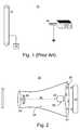
- FIG. 1is a schematic illustration of a prior art electrospinning apparatus
- FIG. 2is a schematic illustration of an electrospinning device for generating a coat from a liquefied polymer, according to the present invention
- FIG. 3is a is a schematic illustration of the electrospinning device further comprising a mechanism for intertwining at least a portion of the polymer fibers, according to the present invention
- FIG. 4is a schematic illustration of the intertwining mechanism in the form of a plurality of stationary electrodes, according to the present invention.
- FIG. 5is a schematic illustration of the intertwining mechanism in the form of at least one rotating electrodes, according to the present invention.
- the present inventionis of an electrospinning device which can be used for generating a coat from a liquefied polymer. Specifically, the present invention can be used to provide first aid for wounds, burns, cuts and the like, and to fabricate artificial skin. Additionally, the present invention can be used to record fingerprints, to connect any two objects such as blood vessels, and to provide a coat to various objects having composite shapes.
- FIGS. 2-5 of the drawingsFor purposes of better understanding the present invention, as illustrated in FIGS. 2-5 of the drawings, reference is first made to the construction and operation of a conventional (i.e., prior art) electrospinning apparatus as illustrated in FIG. 1 .
- FIG. 1illustrates an apparatus for manufacturing a nonwoven material using a conventional electrospinning apparatus, which is referred to herein as apparatus 10 .
- Apparatus 10includes a dispenser 12 which can be, for example, a bath provided with one or more capillary apertures 14 .
- Dispenser 12serves for storing the polymer to be spun in a liquid form, i.e., dissolved or melted.
- Dispenser 12is positioned at a predetermined distance from a precipitation electrode 16 .
- Precipitation electrode 16serves for forming a structure thereupon.
- Precipitation electrode 16is typically manufactured in accordance with the geometrical properties of the final product which is to be fabricated.
- Dispenser 12is typically grounded, while precipitation electrode 16 is connected to a source of high voltage, preferably of negative polarity, thus forming an electric field between dispenser 12 and precipitation electrode 16 .
- precipitation electrode 16can be grounded while dispenser 12 is connected to a source 18 of high voltage with positive polarity.
- a liquefied polymere.g., melted polymer or dissolved polymer
- a pumpnot shown in FIG. 1
- capillary apertures 14 of dispenser 12As soon as meniscus of the extruded liquefied polymer forms, a process of solvent evaporation or cooling starts, which is accompanied by the creation of capsules with a semi-rigid envelope or crust.
- An electric fieldoccasionally accompanied by a unipolar corona discharge in the area of dispenser 12 , is generated by the potential difference between dispenser 12 and precipitation electrode 16 .
- the above-described capsulesbecome charged. Electric forces of repulsion within the capsules lead to a drastic increase in hydrostatic pressure.
- the semi-rigid envelopesare stretched, and a number of point micro-ruptures are formed on the surface of each envelope leading to spraying of ultra-thin jets of liquefied polymer from dispenser 12 .
- the jetsdepart from dispenser 12 and travel towards the opposite polarity electrode, i.e., precipitation electrode 16 .
- the jetcools or solvent therein evaporates, thus forming fibers which are collected on the surface of precipitation electrode 16 .
- the electric field magnitude in the vicinity of precipitation electrode 16may exceed the air electric strength (about 30 kV/cm), and a corona discharge may develop in the area of precipitation electrode 16 .
- the effect of corona dischargedecreases the coating efficiency of the process as described hereinbelow, and may even resultant in a total inability of fibers to be collected upon precipitation electrode 16 .
- Corona discharge initiationis accompanied by the generation of a considerable amount of air ions having opposite charge sign with respect to the charged fibers. Since an electric force is directed with respect to the polarity of charges on which it acts, theses ions start to move at the opposite direction to fibers motion i.e., from precipitation electrode 16 towards dispenser 12 . Consequently, a portion of these ions generate a volume charge (ion cloud), non-uniformly distributed in the inter-electrode space, thereby causing electric field lines to partially close on the volume charge rather than on precipitation electrode 16 .
- apparatus 10is typically designed for manufacturing a nonwoven material having a predetermined structure, or for coating an object which is mounted on a rotating mandrel.
- apparatus 10cannot be used for coating objects which are too large or too complicated for being mounted on a rotating mandrel, or for coating a portion of a blood vessel during surgery.
- the precipitationis done within a substantially high electric field, thus the process may only be employed for coating objects which may be positioned under high voltage. Furthermore, the presence of electric field near precipitation electrode 16 prevents fibers from penetrating into narrow openings, inclined shapes, etc. whenever such structures exist in precipitation electrode 16 .
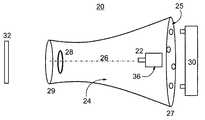
- FIG. 2illustrates an electrospinning device, generally referred to herein as device 20 , for generating a coat from a liquefied polymer according to the teachings of the present invention.
- Device 20includes a dispenser 22 for dispensing the liquefied polymer, and a cavity 24 having a longitudinal axis 26 , and comprising a first system of electrodes 28 .
- System of electrodes 28may be, for example, a circular electrode.
- dispenser 22 and first system of electrodes 28are constructed and design such that the liquefied polymer is dispensed from dispenser 22 and forms a plurality of polymer fibers moving along longitudinal axis 26 , as detailed hereinabove with respect to apparatus 10 . Hence dispenser 22 and system of electrodes 28 are kept under a potential difference generate an electric field therebetween.
- Device 20further includes a mechanism 30 for relocating the polymer fibers out of cavity 24 , in a direction of an object 32 , so as to generate a coat on object 32 .
- Mechanism 30may include, for example, at least one blower, positioned adjacent to dispenser 22 . The blower is configured to generate an airflow substantially directed along longitudinal axis 26 , to maintain the velocity of the polymer fiber while passing near system 28 .
- Cavity 24preferably comprises a perforated plate 25 positioned at a first terminal 27 of cavity 24 , so as to allow sufficient airflow from mechanism 30 which is preferably located outside cavity 24 , behind dispenser 22 . At a second terminal 29 , near system of electrodes 28 , cavity 24 is opened.
- cavity 24is designed such that the airflow velocity increases as a function of a distance from dispenser 22 along longitudinal axis 26 .
- a typical example for such designis a gradually decreased cross-sectional area of cavity 24 as a function of a distance from dispenser 22 along longitudinal axis 26 .
- dispenser 22 and system of electrodes 28are kept under a potential difference.
- dispenser 22is kept under a positive polarity potential and both system of electrodes 28 and object 32 are grounded, i.e., being at earth-zero potential.
- Such electrostatic configurationis intended to substantially diminish any remnant component of electric field between apparatus 20 and object 32 .
- dispenser 22comprises a mechanism for forming a jet of the liquefied polymer, such as, but not limited to, a dispensing electrode, manufactured as a needle. Additionally, dispenser 22 may include a first reservoir 36 for holding the liquefied polymer.
- a jet of the liquefied polymeris dispensed by dispenser 22 , and then, subjected to the electric field, moves through cavity 24 , substantially along longitudinal axis 26 .
- the jetcools or solvent therein evaporates, thus forming the polymer fibers. Beside the electrical forces present between the charged fibers and the electric field, additional mechanical forces, generated by mechanism 30 , act on the polymer fibers concertedly with the electric forces.
- device 20which may be manufactured as a compact portable device, essentially serves as an electrostatic sprayer. Since outside the device the electric field is absent, orientation of fiber movement is maintained only by the mechanical forces due to airflow, which are sufficient for fiber relocation. Since air flow is known to have a decaying property, the velocity of the polymer fibers decreases as a function of a distance from device 20 . Hence, the polymer fibers arrive to object 32 , while moving with nearly zero velocity. Due to Coulomb forces present between the charged polymer fibers and the grounded object, the polymer fibers finally sediment on object 32 .
- the nonwoven material formed by device 20may be required to enhance the strength and/or elasticity of the final product. This is especially important in medical applications, such as wound dressings, where a combination of high elasticity, strength, small thickness, porosity, and low basis weight are required.
- the strength of the nonwoven materialmay be significantly enhanced, by employing an additional electric field having at least one rotating element, as described hereinbelow.
- device 20further includes a mechanism 52 for intertwining at least a portion of the polymer fibers, so as to provide at least one polymer fiber bundle moving in a direction system 28 .
- Mechanism 52may include any mechanical and/or electronic components which are capable for intertwining the polymer fibers “on the fly”, as is further detailed hereinunder, with reference to FIGS. 4-5 .
- FIG. 4illustrates one embodiment of the present invention in which mechanism 52 includes a second system of electrodes being laterally displaced from dispenser 22 and preferably at a second potential relative to dispenser 22 .
- the second system of electrodesmay be constructed in any way known in the art for providing an electric field rotating around longitudinal axis 26 .
- the second system of electrodesmay include two or more stationary electrodes 62 , connected to at least one power source 64 , so that the potential difference between electrodes 62 and system 28 (and between electrodes 62 and dispenser 22 ) varies in time.
- Power sources 64being electronically communicating with each other so as to synchronize a relative phase between electrodes 62 .
- each of stationary electrodes 62generates a time-dependent electric field having a constant direction.
- the electronic communication between power sources 64ensures that the sum of all (time-dependent) field vectors is rotating around longitudinal axis 26 .
- mechanism 52is manufactured as at least one rotating electrode 72 , operable to rotate around longitudinal axis 26 .
- Rotating electrode 72being at a second potential relative to dispenser 22 , generates an electric field, the direction of which follows the motion of rotating electrode 72 , hence an electric field having at least one rotating component is generated.
- the liquefied polymerin operation mode of device 20 , is dispensed by dispenser 22 , and then, subjected to the electric field, moves inside cavity 24 .
- the electric fieldhas at least one rotating component around longitudinal axis 26 (generated by the potential difference between mechanism 52 and system 28 ) and a stationary electric field (generated by the potential difference between dispenser 22 and system 28 ).
- the jets of liquefied polymerunder the effect of the rotating component of the electric field twist around longitudinal axis 26 .
- the rotation frequencymay be controlled by a suitable choice of configuration for the system of electrodes, as well as on the value of the potential differences employed.
- the effect of the rotating component of the electric field on the jets neighboring mechanism 52is larger than the effect on the jets which are located far from mechanism 52 .
- the trajectories of the fibersstart crossing one another, resulting in physical contacts and entanglement between fibers prior to precipitation.
- device 20generates higher-order formations of fiber bundles from the elementary fibers in the spray jet.
- the structure of the formed fiber bundlesis inhomogeneous and depends on the distance of the fiber bundle from mechanism 52 . Specifically, the extent of fiber twisting and interweaving, and the amount of fibers in the bundle, is an increasing function of the distance from mechanism 52 . During the motion of the bundles in cavity 24 , they may also intertwine with one another, forming yet thicker bundles.
- the formed materialhas three-dimensional reticular structure, characterized by a large number of sliding contacts between fibers. Such contacts significantly increase the strength of the material, due to friction forces between fibers. The ability of fibers for mutual displacement increases the elasticity of the nonwoven material under loading.
- Device 20may provide enhanced coating onto numerous kinds of objects, for medical as well as for industrial purposes.
- object 32may be, for example, a portion of a body of an organism, such as but not limited to, a skin an artery and a vein.
- the present inventioncan be used to provide a nonwoven coat onto both internal and external organs.
- object 32may be a rotating mandrel having an intricate-profile structure.
- the present inventioncan be used to provide wound dressing without the need to stretch the dressing, prior to or during application.
- a method of wound dressing by electrospinningcomprises the following steps which may be executed, for example, using device 20 .
- a liquefied polymeris dispensed within a first electric field present in a cavity having a longitudinal axis, thereby providing a plurality of polymer fibers moving along the longitudinal axis.
- the polymer fibersare being relocated out of the cavity, in a direction of an object so as to generate a wound dressing thereupon.
- the methodmay further comprise the step of intertwining at least a portion of the polymer fibers, so as to provide at least one polymer fiber bundle moving in the direction of the object.
- the liquefied polymermay be chosen, as further detailed hereinunder, so as to allow maximal flexibility of the dressing. Moreover, since the process wound dressing (as employed, e.g., by device 20 ) requires no hand contact with the nonwoven material during application, the present invention successfully maintains the sterility of the dressing during the application process.
- the methodmay further comprise the step of incorporating at least one drug within the liquefied polymer, for delivery of the drug into the wound during or after generating the wound dressing.
- a nonwoven sterile wound dressingcomprising at least one layer of polymer fibers shaped in accordance with an individual wound and body geometry.
- the wound dressinghaving various physical, mechanical and pharmacological, properties, which may be any combination of the following characteristics: (a) having a predetermined porosity; (b) flexible in accordance with a motion of the individual; (c) removable when placed under a sufficient amount of liquid; and (d) having at least one drug incorporated therein, for delivery of the drug into a body vasculature during or after application of the wound dressing.
- the wound dressingmay serve, at least temporarily, as an artificial skin, preventing exposure to infectious agents.
- device 20 and the method described aboveare useful in many other industrial applications.
- the present inventioncan be employed for identification of individuals via fingerprints.
- a method of recording a fingerprint of a finger of an individualcomprising the steps of coating the finger by a nonwoven material and removing the nonwoven material from the finger so as to produce data information representative of the fingerprint of the finger.
- the step of coating the fingeris similar to the coating process detailed hereinabove, and it may be executed, for example, using device 20 .
- a mirror image of the fingerprintis obtained on the inner surface of the coat.
- This mirror imagemay be processed in any method known in the art for the purpose of identifying the individual, constructing an appropriate data base or for any other purpose.
- the polymer fibersare manufactured with predetermined magnetic properties, so that the coat, once removed from the finger, may be used as an electronic identification device.
- Such a devicemay be used, e.g., as an “electronic key”, which biometrically identifies a user by his fingerprint.
- the present inventioncan also be used for adhering two objects. This can be done by more than one way.
- the adheringis done by coating (employing the above described method) at least one contact surface and attaching the objects to one another.
- the liquefied polymeris preferably selected to have dominant adhesive properties.
- the two objectsmay be, for example, two blood vessels having open ends which need to be connected to one another during a surgery operation.
- the liquefied polymeris preferably selected to have dominant biological properties, such as, but not limited to, biocompatibility and/or biodegradability.
- the method of connecting the vesselscomprises the steps of attaching the two open ends and, via electrospinning (using the method described above) providing a coat onto at least a portion of the two vessels so as to adhere the two open ends.
- the liquefied polymer loaded into dispenser 22may be, for example polyurethane, polyester, polyolefin, polymethylmethacrylate, polyvinyl aromatic, polyvinyl ester, polyamide, polyimide, polyether, polycarbonate, polyacrilonitrile, polyvinyl pyrrolidone, polyethylene oxide, poly (L-lactic acid), poly (lactide-CD-glycoside), polycaprolactone, polyphosphate ester, poly (glycolic acid), poly (DL-lactic acid), and some copolymers.
- Biolmoleculessuch as DNA, silk, chitozan and cellulose may also be used in mix with synthetic polymers. Improved charging of the polymer may also be required.
- Improved chargingis effected according to the present invention by mixing the liquefied polymer with a charge control agent (e.g., a dipolar additive) to form, for example, a polymer-dipolar additive complex which apparently better interacts with ionized air molecules formed under the influence of the electric field.
- a charge control agente.g., a dipolar additive
- the charge control agentis typically added in the grams equivalent per liter range, say, in the range of from about 0.001 N to about 0.1 N, depending on the respective molecular weights of the polymer and the charge control agent used.
- U.S. Pat. Nos. 5,726,107; 5,554,722; and 5,558,809teach the use of charge control agents in combination with polycondensation processes in the production of electret fibers, which are fibers characterized in a permanent electric charge, using melt spinning and other processes devoid of the use of a precipitation electrode.
- a charge control agentis added in such a way that it is incorporated into the melted or partially melted fibers and remains incorporated therein to provide the fibers with electrostatic charge which is not dissipating for prolonged time periods, say weeks or months.
- the charge control agenttransiently binds to the outer surface of the fibers and therefore the charge dissipates shortly thereafter. This is because polycondensation is not exercised at all such that the chemical interaction between the agent and the polymer is absent, and further due to the low concentration of charge control agent employed. The resulting material is therefore, if so desired, substantially charge free.
- Suitable charge control agentsinclude, but are not limited to, mono- and poly-cyclic radicals that can bind to the polymer molecule via, for example, —C ⁇ C—, ⁇ C—SH— or —CO—NH— groups, including biscationic amides, phenol and uryl sulfide derivatives, metal complex compounds, triphenylmethanes, dimethylmidazole and ethoxytrimethylsians.
Landscapes
- Engineering & Computer Science (AREA)
- Textile Engineering (AREA)
- Health & Medical Sciences (AREA)
- Mechanical Engineering (AREA)
- Chemical & Material Sciences (AREA)
- Epidemiology (AREA)
- Public Health (AREA)
- Medicinal Chemistry (AREA)
- Oral & Maxillofacial Surgery (AREA)
- Transplantation (AREA)
- Dispersion Chemistry (AREA)
- Life Sciences & Earth Sciences (AREA)
- Animal Behavior & Ethology (AREA)
- General Health & Medical Sciences (AREA)
- Dermatology (AREA)
- Veterinary Medicine (AREA)
- Spinning Methods And Devices For Manufacturing Artificial Fibers (AREA)
- Nonwoven Fabrics (AREA)
- Prostheses (AREA)
- Materials For Medical Uses (AREA)
- Control Of El Displays (AREA)
- Rigid Pipes And Flexible Pipes (AREA)
Abstract
Description
Claims (26)
Applications Claiming Priority (3)
| Application Number | Priority Date | Filing Date | Title |
|---|---|---|---|
| US27695601P | 2001-03-20 | 2001-03-20 | |
| US09/982,017US20020084178A1 (en) | 2000-12-19 | 2001-10-19 | Method and apparatus for manufacturing polymer fiber shells via electrospinning |
| PCT/IL2002/000220WO2002074191A2 (en) | 2001-03-20 | 2002-03-19 | Portable electrospinning device |
Publications (2)
| Publication Number | Publication Date |
|---|---|
| US20040094873A1 US20040094873A1 (en) | 2004-05-20 |
| US7794219B2true US7794219B2 (en) | 2010-09-14 |
Family
ID=26958224
Family Applications (1)
| Application Number | Title | Priority Date | Filing Date |
|---|---|---|---|
| US10/471,278Active2027-12-15US7794219B2 (en) | 2001-03-20 | 2002-03-19 | Portable electrospinning device |
Country Status (7)
| Country | Link |
|---|---|
| US (1) | US7794219B2 (en) |
| EP (3) | EP1377420B1 (en) |
| JP (3) | JP4130364B2 (en) |
| AT (1) | ATE473082T1 (en) |
| AU (3) | AU2002241221A1 (en) |
| DE (1) | DE60236919D1 (en) |
| WO (3) | WO2002074191A2 (en) |
Cited By (14)
| Publication number | Priority date | Publication date | Assignee | Title |
|---|---|---|---|---|
| US20080208323A1 (en)* | 2007-01-30 | 2008-08-28 | El-Kurdi Mohammed S | Bioerodible wraps and uses therefor |
| US8992594B2 (en) | 2009-12-16 | 2015-03-31 | Neograft Technologies, Inc. | Graft devices and methods of use |
| WO2015095512A1 (en)* | 2013-12-18 | 2015-06-25 | Zeus Industrial Products, Inc. | Electrospinning slot die design & application |
| US9155610B2 (en) | 2011-12-13 | 2015-10-13 | Neograft Technologies, Inc. | System and atraumatic mandrel for creating graft devices |
| US9295541B2 (en) | 2009-12-31 | 2016-03-29 | Neograft Technologies, Inc. | Graft devices and methods of fabrication |
| US9445874B2 (en) | 2010-07-19 | 2016-09-20 | Neograft Technologies, Inc. | Graft devices and methods of use |
| US9579224B2 (en) | 2011-07-25 | 2017-02-28 | Neograft Technologies, Inc. | Vessel remodeling methods and devices for use in a graft device |
| US10278685B2 (en) | 2015-04-01 | 2019-05-07 | Covidien Lp | Electrospinning device and method for applying polymer to tissue |
| US10639203B2 (en) | 2014-11-11 | 2020-05-05 | Nicast Ltd. | Portable electrospinning device |
| WO2020243684A1 (en) | 2019-05-30 | 2020-12-03 | Skinner Jack L | Device for polymer materials fabrication using gas flow and electrostatic fields |
| WO2023021070A1 (en) | 2021-08-19 | 2023-02-23 | Swansea University | Fluid ionising device |
| US11850141B2 (en) | 2009-10-28 | 2023-12-26 | University of Pittsburgh—of the Commonwealth System of Higher Education | Bioerodible wraps and uses therefor |
| US12234575B1 (en) | 2024-07-22 | 2025-02-25 | The Florida International University Board Of Trustees | Devices and methods for nanofiber-based membrane fabrication |
| EP4563696A1 (en) | 2023-12-01 | 2025-06-04 | Slavka, Jancova | Method of preparation of biomass to promote healing of hypertrophic scars and keloids, biomass and its use |
Families Citing this family (71)
| Publication number | Priority date | Publication date | Assignee | Title |
|---|---|---|---|---|
| US20070031607A1 (en)* | 2000-12-19 | 2007-02-08 | Alexander Dubson | Method and apparatus for coating medical implants |
| US20020084178A1 (en) | 2000-12-19 | 2002-07-04 | Nicast Corporation Ltd. | Method and apparatus for manufacturing polymer fiber shells via electrospinning |
| US7244272B2 (en) | 2000-12-19 | 2007-07-17 | Nicast Ltd. | Vascular prosthesis and method for production thereof |
| KR100549140B1 (en)* | 2002-03-26 | 2006-02-03 | 이 아이 듀폰 디 네모아 앤드 캄파니 | Ultra-fine nanofiber web manufacturing method by electro-blowing |
| US7270675B2 (en)* | 2002-05-10 | 2007-09-18 | Cordis Corporation | Method of forming a tubular membrane on a structural frame |
| EP1670595A4 (en)* | 2003-10-06 | 2010-07-21 | Nicast Ltd | Method and apparatus for coating medical implants |
| US7935298B2 (en)* | 2003-12-23 | 2011-05-03 | Virginia Commonwealth University | Method of producing fibers by electrospinning at high pressures |
| US20080200975A1 (en)* | 2004-01-06 | 2008-08-21 | Nicast Ltd. | Vascular Prosthesis with Anastomotic Member |
| GB0402736D0 (en)* | 2004-02-06 | 2004-03-10 | Tayside Flow Technologies Ltd | A drug delivery device |
| US7592277B2 (en) | 2005-05-17 | 2009-09-22 | Research Triangle Institute | Nanofiber mats and production methods thereof |
| US7134857B2 (en) | 2004-04-08 | 2006-11-14 | Research Triangle Institute | Electrospinning of fibers using a rotatable spray head |
| US7297305B2 (en) | 2004-04-08 | 2007-11-20 | Research Triangle Institute | Electrospinning in a controlled gaseous environment |
| US7762801B2 (en) | 2004-04-08 | 2010-07-27 | Research Triangle Institute | Electrospray/electrospinning apparatus and method |
| US20080241538A1 (en)* | 2004-06-17 | 2008-10-02 | Korea Research Institute Of Chemical Technology | Filament Bundle Type Nano Fiber and Manufacturing Method Thereof |
| TWI245085B (en)* | 2004-07-29 | 2005-12-11 | Taiwan Textile Res Inst | Apparatus and method for manufacturing polymeric fibrils |
| US8808608B2 (en)* | 2004-12-27 | 2014-08-19 | E I Du Pont De Nemours And Company | Electroblowing web formation process |
| US7585451B2 (en)* | 2004-12-27 | 2009-09-08 | E.I. Du Pont De Nemours And Company | Electroblowing web formation process |
| US10328032B2 (en)* | 2005-03-04 | 2019-06-25 | Biosurfaces, Inc. | Nanofibrous materials as drug, protein, or genetic release vehicles |
| WO2006096791A2 (en)* | 2005-03-07 | 2006-09-14 | Georgia Tech Research Corporation | Nanofilament scaffold for tissue regeneration |
| NL1028847C2 (en)* | 2005-04-22 | 2006-10-24 | Univ Eindhoven Tech | Method and device for manufacturing and controlling a fiber from an material with the aid of an electric field, and article thus produced. |
| JP4979264B2 (en)* | 2006-05-11 | 2012-07-18 | 兵庫県 | Method for producing density gradient nonwoven fabric |
| JP4710783B2 (en)* | 2006-10-02 | 2011-06-29 | パナソニック株式会社 | Electrostatic discharge method and apparatus, electrostatic work method and apparatus using them |
| JP2008095266A (en)* | 2006-10-12 | 2008-04-24 | Hodai Lee | Conjugate fiber filter using nano material, production equipment of conjugate fiber filter using nano material and production method of conjugate fiber filter using nano material |
| JP5224704B2 (en)* | 2007-03-14 | 2013-07-03 | 株式会社メック | Nano-fiber manufacturing method and apparatus |
| AU2008261691A1 (en)* | 2007-06-11 | 2008-12-18 | Nanovasc, Inc. | Stents |
| ITTO20080252A1 (en)* | 2008-04-01 | 2009-10-02 | Fondazione Istituto Italiano Di Tecnologia | PROCEDURE FOR THE PRODUCTION OF FUNCTIONAL FABRIC BASED ON CARBON FIBER |
| CN101559243A (en)* | 2008-04-18 | 2009-10-21 | 中国科学院上海硅酸盐研究所 | Preparation method of tubular electrospinning fibre material |
| JP5007474B2 (en)* | 2008-06-09 | 2012-08-22 | パナソニック株式会社 | Non-bonded cylinder manufacturing apparatus, non-bonded cylinder manufacturing method |
| JP4965521B2 (en)* | 2008-07-08 | 2012-07-04 | パナソニック株式会社 | Nanofiber manufacturing equipment |
| JP4965525B2 (en)* | 2008-07-18 | 2012-07-04 | パナソニック株式会社 | Nanofiber manufacturing apparatus and nanofiber manufacturing method |
| JP4966932B2 (en)* | 2008-09-01 | 2012-07-04 | パナソニック株式会社 | Nanofiber manufacturing apparatus and nanofiber manufacturing method |
| JP5215136B2 (en)* | 2008-11-18 | 2013-06-19 | パナソニック株式会社 | Nanofiber manufacturing apparatus and nanofiber manufacturing method |
| WO2010059127A1 (en)* | 2008-11-20 | 2010-05-27 | National University Of Singapore | A portable electrospinning apparatus |
| JP5185090B2 (en)* | 2008-12-02 | 2013-04-17 | パナソニック株式会社 | Nanofiber manufacturing method and manufacturing apparatus |
| JP5227198B2 (en)* | 2009-01-07 | 2013-07-03 | パナソニック株式会社 | Nanofiber manufacturing apparatus and nanofiber manufacturing method |
| JP5234355B2 (en)* | 2009-01-15 | 2013-07-10 | パナソニック株式会社 | Nanofiber manufacturing apparatus and manufacturing method |
| CN102301044B (en)* | 2009-02-05 | 2013-10-23 | 松下电器产业株式会社 | Nanofiber manufacturing device, nanofiber manufacturing method |
| JP5225885B2 (en)* | 2009-02-16 | 2013-07-03 | パナソニック株式会社 | Nanofiber manufacturing apparatus and manufacturing method |
| JP2010229563A (en)* | 2009-03-25 | 2010-10-14 | Teijin Ltd | Method for producing particle-polymer fibrous composite |
| US9492652B2 (en)* | 2010-03-02 | 2016-11-15 | University Of Rochester | Implantable devices that generate low intensity electric fields for the treatment of atherosclerotic disease and prevention of ischemic vascular events and methods of manufacture |
| EP2659034B1 (en) | 2010-12-29 | 2019-02-20 | University of Pittsburgh - Of the Commonwealth System of Higher Education | System and method for mandrel-less electrospinning |
| EP2663265A4 (en) | 2011-01-14 | 2016-05-25 | Neograft Technologies Inc | Apparatus for creating graft devices |
| US9867690B2 (en) | 2011-02-09 | 2018-01-16 | Neograft Technologies, Inc. | System and mandrel for creating graft devices |
| ES2666857T3 (en) | 2011-07-18 | 2018-05-08 | Mor-Research Applications Ltd. | A device to adjust intraocular pressure |
| FR2987373B1 (en)* | 2012-02-27 | 2014-07-25 | Univ Claude Bernard Lyon | METHOD FOR MANUFACTURING CONTINUOUS YARNS COMPRISING AN ASSEMBLY OF FILAMENTS AND YARNS OBTAINED |
| CN102961788B (en)* | 2012-12-04 | 2015-08-12 | 东华大学 | A kind of heparin load aneurysm treatment overlay film frame and preparation method thereof |
| CN103147225A (en)* | 2013-02-06 | 2013-06-12 | 东华大学 | Preparation method for protein-polyose-polylactic acid polycaprolactone vascular stent |
| CN103147229B (en)* | 2013-03-25 | 2015-05-13 | 东华大学 | Method for preparing collagen/lactic acid-caprolactone copolymer composite fiber bracket |
| CN103266421B (en)* | 2013-06-09 | 2014-07-02 | 东华大学 | A kind of preparation method of caprolactone lactate copolymer/collagen/chitosan small-caliber vascular stent |
| KR101501383B1 (en)* | 2013-10-30 | 2015-03-10 | 가톨릭대학교 산학협력단 | Nanofiber scaffold with an aligned structure and method thereof |
| KR101635032B1 (en)* | 2014-08-13 | 2016-06-30 | 박종철 | Mobile electrospinning device |
| KR101635027B1 (en)* | 2014-08-13 | 2016-06-30 | 박종철 | Portable electrospinning device |
| WO2016024720A1 (en)* | 2014-08-13 | 2016-02-18 | 박종철 | Mobile or portable electrospinning apparatus |
| CN107667190B (en)* | 2015-03-24 | 2020-09-11 | 赫尔辛基大学 | Apparatus and method for producing nanofibers and constructs thereof |
| CN104887282B (en)* | 2015-05-25 | 2017-03-08 | 东华大学 | A device for repairing blood vessels |
| CN107979992B (en) | 2015-06-08 | 2020-05-22 | 科尔尼特视觉有限公司 | Artificial cornea and use thereof |
| CN108277540A (en)* | 2017-03-22 | 2018-07-13 | 吴强 | A kind of integral type blowing electrostatic spinning device |
| KR102208595B1 (en) | 2017-04-19 | 2021-01-28 | 카오카부시키가이샤 | Film production method |
| CN110545782B (en)* | 2017-04-19 | 2022-11-04 | 花王株式会社 | Method for producing coating film |
| US20210228770A1 (en) | 2018-06-05 | 2021-07-29 | Corneat Vision Ltd. | A synthetic ophthalmic graft patch |
| JP6882409B2 (en) | 2018-10-03 | 2021-06-02 | 花王株式会社 | Coating manufacturing equipment |
| JP7158364B2 (en) | 2018-11-26 | 2022-10-21 | 花王株式会社 | skin coating |
| WO2020165906A1 (en)* | 2019-02-14 | 2020-08-20 | Technion Research & Development Foundation Limited | Composition, drug delivery device and method for local delivery of an active agent |
| US12364591B2 (en) | 2019-04-25 | 2025-07-22 | Corneat Vision Ltd | Keratoprosthesis devices and kits and surgical methods of their use |
| WO2021028912A1 (en) | 2019-08-12 | 2021-02-18 | Corneat Vision Ltd. | Gingival graft |
| CN114599828B (en)* | 2019-10-28 | 2023-04-07 | 花王株式会社 | Method for producing fiber-stacked body, method for producing film, and method for adhering film |
| WO2021085394A1 (en)* | 2019-10-28 | 2021-05-06 | 花王株式会社 | Fiber deposit production method, membrane production method, and membrane adhesion method |
| CN111705431A (en)* | 2020-06-30 | 2020-09-25 | 西北大学 | A preparation method of water-soluble nanopaper and its application in fingerprint structure acquisition |
| JP2025508762A (en) | 2022-02-27 | 2025-04-10 | コルニート ヴィジョン リミテッド | Implantable Sensors |
| EP4598477A1 (en) | 2022-10-03 | 2025-08-13 | Corneat Vision Ltd. | Dental and subperiosteal implants comprising biocompatible graft |
| WO2024209469A1 (en) | 2023-04-03 | 2024-10-10 | Glaucure Ltd | Devices for adjusting the intraocular pressure |
Citations (112)
| Publication number | Priority date | Publication date | Assignee | Title |
|---|---|---|---|---|
| US2491889A (en) | 1942-01-21 | 1949-12-20 | Owens Corning Fiberglass Corp | Production of coated glass and the like products |
| US3280229A (en) | 1963-01-15 | 1966-10-18 | Kendall & Co | Process and apparatus for producing patterned non-woven fabrics |
| US3425418A (en) | 1963-06-15 | 1969-02-04 | Spofa Vereinigte Pharma Werke | Artificial blood vessels and method of preparing the same |
| US3625745A (en) | 1970-03-18 | 1971-12-07 | Gen Electric | Antithrombogenic article and process |
| US3688317A (en) | 1970-08-25 | 1972-09-05 | Sutures Inc | Vascular prosthetic |
| US3860369A (en)* | 1972-11-02 | 1975-01-14 | Du Pont | Apparatus for making non-woven fibrous sheet |
| US4009508A (en)* | 1975-04-30 | 1977-03-01 | Monsanto Company | Method for forwarding and charging a bundle of filaments |
| US4044404A (en) | 1974-08-05 | 1977-08-30 | Imperial Chemical Industries Limited | Fibrillar lining for prosthetic device |
| US4148595A (en)* | 1977-09-28 | 1979-04-10 | E. I. Du Pont De Nemours And Company | Coating for aerodynamic shield in apparatus for making non-woven web |
| US4159640A (en) | 1977-03-04 | 1979-07-03 | L'oreal | Apparatus for measuring the consistency or hardness of a material |
| US4223101A (en) | 1978-07-17 | 1980-09-16 | Inmont Corporation | Method of producing fibrous structure |
| US4323525A (en) | 1978-04-19 | 1982-04-06 | Imperial Chemical Industries Limited | Electrostatic spinning of tubular products |
| US4345414A (en) | 1978-11-20 | 1982-08-24 | Imperial Chemical Industries Limited | Shaping process |
| US4368277A (en) | 1979-03-05 | 1983-01-11 | Burinsky Stanislav V | Porous open-cell filled reactive material |
| EP0009941B1 (en) | 1978-10-10 | 1983-06-15 | Imperial Chemical Industries Plc | Production of electrostatically spun products |
| US4475972A (en) | 1981-10-01 | 1984-10-09 | Ontario Research Foundation | Implantable material |
| US4524036A (en) | 1981-08-10 | 1985-06-18 | University Of Liverpool | Process for the manufacture of polyurethane resin for electrostatic spinning |
| GB2142870B (en) | 1983-07-06 | 1986-06-04 | Ethicon Inc | Manufacturing vascular prostheses by electrostatic spinning |
| US4657793A (en) | 1984-07-16 | 1987-04-14 | Ethicon, Inc. | Fibrous structures |
| EP0253539A2 (en) | 1986-07-17 | 1988-01-20 | Imperial Chemical Industries Plc | Spraying process |
| US4731073A (en) | 1981-02-13 | 1988-03-15 | Thoratec Laboratories Corporation | Arterial graft prosthesis |
| US4739013A (en) | 1985-12-19 | 1988-04-19 | Corvita Corporation | Polyurethanes |
| US4738740A (en) | 1985-11-21 | 1988-04-19 | Corvita Corporation | Method of forming implantable vascular grafts |
| EP0266035A1 (en) | 1986-09-02 | 1988-05-04 | Ethicon, Inc. | Improvements in synthetic vascular grafts |
| US4743252A (en) | 1986-01-13 | 1988-05-10 | Corvita Corporation | Composite grafts |
| US4759757A (en) | 1984-04-18 | 1988-07-26 | Corvita Corporation | Cardiovascular graft and method of forming same |
| US4769030A (en) | 1987-04-28 | 1988-09-06 | Corvita Corporation | Monomer and use thereof in crack prevention of implanted prostheses |
| US4798606A (en) | 1985-02-26 | 1989-01-17 | Corvita Corporation | Reinforcing structure for cardiovascular graft |
| US4802145A (en) | 1986-08-01 | 1989-01-31 | Amoco Corporation | Method and apparatus for determining cement conditions |
| US4842505A (en) | 1986-03-24 | 1989-06-27 | Ethicon | Apparatus for producing fibrous structures electrostatically |
| US4872455A (en) | 1987-11-25 | 1989-10-10 | Corvita Corporation | Anastomosis trimming device and method of using the same |
| US4880002A (en) | 1985-05-30 | 1989-11-14 | Corvita Corporation | Stretchable porous sutures |
| US4904174A (en)* | 1988-09-15 | 1990-02-27 | Peter Moosmayer | Apparatus for electrically charging meltblown webs (B-001) |
| US4905367A (en) | 1988-11-08 | 1990-03-06 | Corvita Corporation | Manufacture of stretchable porous sutures |
| EP0223374B1 (en) | 1985-10-04 | 1990-08-29 | Ethicon, Inc. | Improvements in electrostatically produced structures and methods of manufacturing thereof |
| US4965110A (en) | 1988-06-20 | 1990-10-23 | Ethicon, Inc. | Electrostatically produced structures and methods of manufacturing |
| US4990158A (en) | 1989-05-10 | 1991-02-05 | United States Surgical Corporation | Synthetic semiabsorbable tubular prosthesis |
| US4997600A (en) | 1988-05-24 | 1991-03-05 | Mitsubishi Monsanto Chemical Company, Ltd. | Process for preparation of thermoplastic resin sheets |
| US5019090A (en) | 1988-09-01 | 1991-05-28 | Corvita Corporation | Radially expandable endoprosthesis and the like |
| US5024789A (en) | 1988-10-13 | 1991-06-18 | Ethicon, Inc. | Method and apparatus for manufacturing electrostatically spun structure |
| US5024671A (en) | 1988-09-19 | 1991-06-18 | Baxter International Inc. | Microporous vascular graft |
| US5084065A (en) | 1989-07-10 | 1992-01-28 | Corvita Corporation | Reinforced graft assembly |
| US5092877A (en) | 1988-09-01 | 1992-03-03 | Corvita Corporation | Radially expandable endoprosthesis |
| US5116360A (en) | 1990-12-27 | 1992-05-26 | Corvita Corporation | Mesh composite graft |
| US5133742A (en) | 1990-06-15 | 1992-07-28 | Corvita Corporation | Crack-resistant polycarbonate urethane polymer prostheses |
| US5147725A (en) | 1990-07-03 | 1992-09-15 | Corvita Corporation | Method for bonding silicone rubber and polyurethane materials and articles manufactured thereby |
| EP0523960A1 (en) | 1991-07-15 | 1993-01-20 | Unilever Plc | Skin treatment system |
| US5226913A (en) | 1988-09-01 | 1993-07-13 | Corvita Corporation | Method of making a radially expandable prosthesis |
| US5298255A (en) | 1988-10-28 | 1994-03-29 | Terumo Kabushiki Kaisha | Antithrombic medical material, artificial internal organ, and method for production of antithrombic medical material |
| US5334201A (en) | 1993-03-12 | 1994-08-02 | Cowan Kevin P | Permanent stent made of a cross linkable material |
| US5360397A (en) | 1993-07-02 | 1994-11-01 | Corvita Corporation | Hemodiaylsis catheter and catheter assembly |
| US5376117A (en) | 1991-10-25 | 1994-12-27 | Corvita Corporation | Breast prostheses |
| US5383922A (en) | 1993-03-15 | 1995-01-24 | Medtronic, Inc. | RF lead fixation and implantable lead |
| US5383928A (en) | 1992-06-10 | 1995-01-24 | Emory University | Stent sheath for local drug delivery |
| US5415664A (en) | 1994-03-30 | 1995-05-16 | Corvita Corporation | Method and apparatus for introducing a stent or a stent-graft |
| US5419760A (en) | 1993-01-08 | 1995-05-30 | Pdt Systems, Inc. | Medicament dispensing stent for prevention of restenosis of a blood vessel |
| US5545208A (en) | 1990-02-28 | 1996-08-13 | Medtronic, Inc. | Intralumenal drug eluting prosthesis |
| US5549663A (en) | 1994-03-09 | 1996-08-27 | Cordis Corporation | Endoprosthesis having graft member and exposed welded end junctions, method and procedure |
| US5554722A (en) | 1993-08-17 | 1996-09-10 | Hoechst Ag | Aromatic polyamide compositions with improved electrostatic properties, formed structures produced therefrom, and use and production thereof |
| US5558809A (en) | 1993-03-09 | 1996-09-24 | Hoechst Celanese Corporation | Polymer electrets with improved charge stability |
| US5575818A (en) | 1995-02-14 | 1996-11-19 | Corvita Corporation | Endovascular stent with locking ring |
| US5591227A (en) | 1992-03-19 | 1997-01-07 | Medtronic, Inc. | Drug eluting stent |
| US5609629A (en) | 1995-06-07 | 1997-03-11 | Med Institute, Inc. | Coated implantable medical device |
| US5624411A (en) | 1993-04-26 | 1997-04-29 | Medtronic, Inc. | Intravascular stent and method |
| US5627368A (en) | 1995-07-05 | 1997-05-06 | Gas Research Institute | Four-detector formation-density tool for use in cased and open holes |
| US5628788A (en) | 1995-11-07 | 1997-05-13 | Corvita Corporation | Self-expanding endoluminal stent-graft |
| US5632772A (en) | 1993-10-21 | 1997-05-27 | Corvita Corporation | Expandable supportive branched endoluminal grafts |
| US5637113A (en) | 1994-12-13 | 1997-06-10 | Advanced Cardiovascular Systems, Inc. | Polymer film for wrapping a stent structure |
| US5639278A (en) | 1993-10-21 | 1997-06-17 | Corvita Corporation | Expandable supportive bifurcated endoluminal grafts |
| US5653747A (en) | 1992-12-21 | 1997-08-05 | Corvita Corporation | Luminal graft endoprostheses and manufacture thereof |
| US5700269A (en) | 1995-06-06 | 1997-12-23 | Corvita Corporation | Endoluminal prosthesis deployment device for use with prostheses of variable length and having retraction ability |
| US5723004A (en) | 1993-10-21 | 1998-03-03 | Corvita Corporation | Expandable supportive endoluminal grafts |
| US5726107A (en) | 1994-08-30 | 1998-03-10 | Hoechst Aktiengesellschaft | Non-wovens of electret fiber mixtures having an improved charge stability |
| US5733327A (en) | 1994-10-17 | 1998-03-31 | Igaki; Keiji | Stent for liberating drug |
| US5741333A (en) | 1995-04-12 | 1998-04-21 | Corvita Corporation | Self-expanding stent for a medical device to be introduced into a cavity of a body |
| US5749921A (en) | 1996-02-20 | 1998-05-12 | Medtronic, Inc. | Apparatus and methods for compression of endoluminal prostheses |
| US5755722A (en) | 1994-12-22 | 1998-05-26 | Boston Scientific Corporation | Stent placement device with medication dispenser and method |
| US5755774A (en) | 1994-06-27 | 1998-05-26 | Corvita Corporation | Bistable luminal graft endoprosthesis |
| US5755778A (en) | 1996-10-16 | 1998-05-26 | Nitinol Medical Technologies, Inc. | Anastomosis device |
| US5766710A (en) | 1994-06-27 | 1998-06-16 | Advanced Cardiovascular Systems, Inc. | Biodegradable mesh and film stent |
| US5797887A (en) | 1996-08-27 | 1998-08-25 | Novovasc Llc | Medical device with a surface adapted for exposure to a blood stream which is coated with a polymer containing a nitrosyl-containing organo-metallic compound which releases nitric oxide from the coating to mediate platelet aggregation |
| US5824049A (en) | 1995-06-07 | 1998-10-20 | Med Institute, Inc. | Coated implantable medical device |
| US5824048A (en) | 1993-04-26 | 1998-10-20 | Medtronic, Inc. | Method for delivering a therapeutic substance to a body lumen |
| US5843172A (en) | 1997-04-15 | 1998-12-01 | Advanced Cardiovascular Systems, Inc. | Porous medicated stent |
| US5849037A (en) | 1995-04-12 | 1998-12-15 | Corvita Corporation | Self-expanding stent for a medical device to be introduced into a cavity of a body, and method for its preparation |
| US5855598A (en) | 1993-10-21 | 1999-01-05 | Corvita Corporation | Expandable supportive branched endoluminal grafts |
| US5900246A (en) | 1993-03-18 | 1999-05-04 | Cedars-Sinai Medical Center | Drug incorporating and releasing polymeric coating for bioprosthesis |
| US5938697A (en) | 1998-03-04 | 1999-08-17 | Scimed Life Systems, Inc. | Stent having variable properties |
| US5968091A (en) | 1996-03-26 | 1999-10-19 | Corvita Corp. | Stents and stent grafts having enhanced hoop strength and methods of making the same |
| US5968070A (en) | 1995-02-22 | 1999-10-19 | Cordis Corporation | Covered expanding mesh stent |
| US5980972A (en) | 1996-12-20 | 1999-11-09 | Schneider (Usa) Inc | Method of applying drug-release coatings |
| US5980551A (en) | 1997-02-07 | 1999-11-09 | Endovasc Ltd., Inc. | Composition and method for making a biodegradable drug delivery stent |
| US6001125A (en) | 1996-01-22 | 1999-12-14 | Meadox Medicals, Inc. | PTFE vascular prosthesis and method of manufacture |
| US6004346A (en) | 1990-02-28 | 1999-12-21 | Medtronic, Inc. | Intralumenal drug eluting prosthesis |
| US6013099A (en) | 1998-04-29 | 2000-01-11 | Medtronic, Inc. | Medical device for delivering a water-insoluble therapeutic salt or substance |
| US6017362A (en) | 1994-04-01 | 2000-01-25 | Gore Enterprise Holdings, Inc. | Folding self-expandable intravascular stent |
| US6019788A (en) | 1996-11-08 | 2000-02-01 | Gore Enterprise Holdings, Inc. | Vascular shunt graft and junction for same |
| US6019789A (en) | 1998-04-01 | 2000-02-01 | Quanam Medical Corporation | Expandable unit cell and intraluminal stent |
| US6023170A (en) | 1995-06-08 | 2000-02-08 | Instituut Voor Milieu- En Agritechniek | Method for determining the degree of hardening of a material |
| US6102939A (en) | 1996-07-29 | 2000-08-15 | Corvita Corporation | Method of implanting biostable elastomeric polymers having quaternary carbons |
| US6106913A (en) | 1997-10-10 | 2000-08-22 | Quantum Group, Inc | Fibrous structures containing nanofibrils and other textile fibers |
| US6117425A (en) | 1990-11-27 | 2000-09-12 | The American National Red Cross | Supplemented and unsupplemented tissue sealants, method of their production and use |
| US6252129B1 (en) | 1996-07-23 | 2001-06-26 | Electrosols, Ltd. | Dispensing device and method for forming material |
| US6265333B1 (en) | 1998-06-02 | 2001-07-24 | Board Of Regents, University Of Nebraska-Lincoln | Delamination resistant composites prepared by small diameter fiber reinforcement at ply interfaces |
| US6270793B1 (en) | 1999-09-13 | 2001-08-07 | Keraplast Technologies, Ltd. | Absorbent keratin wound dressing |
| US20010020652A1 (en) | 1999-08-18 | 2001-09-13 | Kadlubowski Bryan Michael | Electrostatic spray device |
| US6306424B1 (en) | 1999-06-30 | 2001-10-23 | Ethicon, Inc. | Foam composite for the repair or regeneration of tissue |
| US20020002395A1 (en) | 1997-10-09 | 2002-01-03 | Todd Allen Berg | Graft structures with compliance gradients |
| US20020081732A1 (en) | 2000-10-18 | 2002-06-27 | Bowlin Gary L. | Electroprocessing in drug delivery and cell encapsulation |
| US20020090725A1 (en) | 2000-11-17 | 2002-07-11 | Simpson David G. | Electroprocessed collagen |
| US6604925B1 (en) | 1996-12-11 | 2003-08-12 | Nicast Ltd. | Device for forming a filtering material |
| US20030171053A1 (en) | 1999-11-24 | 2003-09-11 | University Of Washington | Medical devices comprising small fiber biomaterials, and methods of use |
Family Cites Families (2)
| Publication number | Priority date | Publication date | Assignee | Title |
|---|---|---|---|---|
| CN1223340C (en)* | 2000-01-28 | 2005-10-19 | 史密丝克莱恩比彻姆公司 | Electrospun pharmaceutical compositions |
| WO2002040242A1 (en)* | 2000-11-17 | 2002-05-23 | Virginia Commonwealth University Intellectual Property Foundation | Electroprocessed collagen |
- 2002
- 2002-03-19JPJP2002572905Apatent/JP4130364B2/ennot_activeExpired - Lifetime
- 2002-03-19WOPCT/IL2002/000220patent/WO2002074191A2/enactiveApplication Filing
- 2002-03-19EPEP02707070Apatent/EP1377420B1/ennot_activeExpired - Lifetime
- 2002-03-19AUAU2002241221Apatent/AU2002241221A1/ennot_activeAbandoned
- 2002-03-19JPJP2002572904Apatent/JP2004531652A/enactivePending
- 2002-03-19WOPCT/IL2002/000218patent/WO2002074189A2/enactiveApplication Filing
- 2002-03-19AUAU2002241222Apatent/AU2002241222A1/ennot_activeAbandoned
- 2002-03-19EPEP02707069Apatent/EP1377419A4/ennot_activeWithdrawn
- 2002-03-19USUS10/471,278patent/US7794219B2/enactiveActive
- 2002-03-19AUAU2002242929Apatent/AU2002242929A1/ennot_activeAbandoned
- 2002-03-19EPEP02708603Apatent/EP1377421A4/ennot_activeWithdrawn
- 2002-03-19JPJP2002572903Apatent/JP2004530054A/enactivePending
- 2002-03-19ATAT02707070Tpatent/ATE473082T1/ennot_activeIP Right Cessation
- 2002-03-19DEDE60236919Tpatent/DE60236919D1/ennot_activeExpired - Lifetime
- 2002-03-19WOPCT/IL2002/000219patent/WO2002074190A2/enactiveApplication Filing
Patent Citations (123)
| Publication number | Priority date | Publication date | Assignee | Title |
|---|---|---|---|---|
| US2491889A (en) | 1942-01-21 | 1949-12-20 | Owens Corning Fiberglass Corp | Production of coated glass and the like products |
| US3280229A (en) | 1963-01-15 | 1966-10-18 | Kendall & Co | Process and apparatus for producing patterned non-woven fabrics |
| US3425418A (en) | 1963-06-15 | 1969-02-04 | Spofa Vereinigte Pharma Werke | Artificial blood vessels and method of preparing the same |
| US3625745A (en) | 1970-03-18 | 1971-12-07 | Gen Electric | Antithrombogenic article and process |
| US3688317A (en) | 1970-08-25 | 1972-09-05 | Sutures Inc | Vascular prosthetic |
| US3860369A (en)* | 1972-11-02 | 1975-01-14 | Du Pont | Apparatus for making non-woven fibrous sheet |
| US4878908A (en) | 1974-08-05 | 1989-11-07 | Imperial Chemical Industries Plc | Fibrillar product |
| US4044404A (en) | 1974-08-05 | 1977-08-30 | Imperial Chemical Industries Limited | Fibrillar lining for prosthetic device |
| US4009508A (en)* | 1975-04-30 | 1977-03-01 | Monsanto Company | Method for forwarding and charging a bundle of filaments |
| US4159640A (en) | 1977-03-04 | 1979-07-03 | L'oreal | Apparatus for measuring the consistency or hardness of a material |
| US4148595A (en)* | 1977-09-28 | 1979-04-10 | E. I. Du Pont De Nemours And Company | Coating for aerodynamic shield in apparatus for making non-woven web |
| US4323525A (en) | 1978-04-19 | 1982-04-06 | Imperial Chemical Industries Limited | Electrostatic spinning of tubular products |
| US4223101A (en) | 1978-07-17 | 1980-09-16 | Inmont Corporation | Method of producing fibrous structure |
| EP0009941B1 (en) | 1978-10-10 | 1983-06-15 | Imperial Chemical Industries Plc | Production of electrostatically spun products |
| US4689186A (en) | 1978-10-10 | 1987-08-25 | Imperial Chemical Industries Plc | Production of electrostatically spun products |
| US4345414A (en) | 1978-11-20 | 1982-08-24 | Imperial Chemical Industries Limited | Shaping process |
| US4368277A (en) | 1979-03-05 | 1983-01-11 | Burinsky Stanislav V | Porous open-cell filled reactive material |
| US4731073A (en) | 1981-02-13 | 1988-03-15 | Thoratec Laboratories Corporation | Arterial graft prosthesis |
| US4524036A (en) | 1981-08-10 | 1985-06-18 | University Of Liverpool | Process for the manufacture of polyurethane resin for electrostatic spinning |
| US4475972A (en) | 1981-10-01 | 1984-10-09 | Ontario Research Foundation | Implantable material |
| GB2142870B (en) | 1983-07-06 | 1986-06-04 | Ethicon Inc | Manufacturing vascular prostheses by electrostatic spinning |
| US4759757A (en) | 1984-04-18 | 1988-07-26 | Corvita Corporation | Cardiovascular graft and method of forming same |
| US4657793A (en) | 1984-07-16 | 1987-04-14 | Ethicon, Inc. | Fibrous structures |
| US4798606A (en) | 1985-02-26 | 1989-01-17 | Corvita Corporation | Reinforcing structure for cardiovascular graft |
| US4880002A (en) | 1985-05-30 | 1989-11-14 | Corvita Corporation | Stretchable porous sutures |
| EP0223374B1 (en) | 1985-10-04 | 1990-08-29 | Ethicon, Inc. | Improvements in electrostatically produced structures and methods of manufacturing thereof |
| US4738740A (en) | 1985-11-21 | 1988-04-19 | Corvita Corporation | Method of forming implantable vascular grafts |
| US4739013A (en) | 1985-12-19 | 1988-04-19 | Corvita Corporation | Polyurethanes |
| US4743252A (en) | 1986-01-13 | 1988-05-10 | Corvita Corporation | Composite grafts |
| US4842505A (en) | 1986-03-24 | 1989-06-27 | Ethicon | Apparatus for producing fibrous structures electrostatically |
| EP0253539A2 (en) | 1986-07-17 | 1988-01-20 | Imperial Chemical Industries Plc | Spraying process |
| US4802145A (en) | 1986-08-01 | 1989-01-31 | Amoco Corporation | Method and apparatus for determining cement conditions |
| EP0266035A1 (en) | 1986-09-02 | 1988-05-04 | Ethicon, Inc. | Improvements in synthetic vascular grafts |
| US4769030A (en) | 1987-04-28 | 1988-09-06 | Corvita Corporation | Monomer and use thereof in crack prevention of implanted prostheses |
| US4872455A (en) | 1987-11-25 | 1989-10-10 | Corvita Corporation | Anastomosis trimming device and method of using the same |
| US4997600A (en) | 1988-05-24 | 1991-03-05 | Mitsubishi Monsanto Chemical Company, Ltd. | Process for preparation of thermoplastic resin sheets |
| US4965110A (en) | 1988-06-20 | 1990-10-23 | Ethicon, Inc. | Electrostatically produced structures and methods of manufacturing |
| US5019090A (en) | 1988-09-01 | 1991-05-28 | Corvita Corporation | Radially expandable endoprosthesis and the like |
| US5226913A (en) | 1988-09-01 | 1993-07-13 | Corvita Corporation | Method of making a radially expandable prosthesis |
| US5092877A (en) | 1988-09-01 | 1992-03-03 | Corvita Corporation | Radially expandable endoprosthesis |
| US4904174A (en)* | 1988-09-15 | 1990-02-27 | Peter Moosmayer | Apparatus for electrically charging meltblown webs (B-001) |
| US5024671A (en) | 1988-09-19 | 1991-06-18 | Baxter International Inc. | Microporous vascular graft |
| US5024789A (en) | 1988-10-13 | 1991-06-18 | Ethicon, Inc. | Method and apparatus for manufacturing electrostatically spun structure |
| US5298255A (en) | 1988-10-28 | 1994-03-29 | Terumo Kabushiki Kaisha | Antithrombic medical material, artificial internal organ, and method for production of antithrombic medical material |
| US4905367A (en) | 1988-11-08 | 1990-03-06 | Corvita Corporation | Manufacture of stretchable porous sutures |
| US4990158A (en) | 1989-05-10 | 1991-02-05 | United States Surgical Corporation | Synthetic semiabsorbable tubular prosthesis |
| US5084065A (en) | 1989-07-10 | 1992-01-28 | Corvita Corporation | Reinforced graft assembly |
| US5545208A (en) | 1990-02-28 | 1996-08-13 | Medtronic, Inc. | Intralumenal drug eluting prosthesis |
| US6004346A (en) | 1990-02-28 | 1999-12-21 | Medtronic, Inc. | Intralumenal drug eluting prosthesis |
| US5725567A (en) | 1990-02-28 | 1998-03-10 | Medtronic, Inc. | Method of making a intralumenal drug eluting prosthesis |
| US5133742A (en) | 1990-06-15 | 1992-07-28 | Corvita Corporation | Crack-resistant polycarbonate urethane polymer prostheses |
| US5147725A (en) | 1990-07-03 | 1992-09-15 | Corvita Corporation | Method for bonding silicone rubber and polyurethane materials and articles manufactured thereby |
| US6117425A (en) | 1990-11-27 | 2000-09-12 | The American National Red Cross | Supplemented and unsupplemented tissue sealants, method of their production and use |
| US5116360A (en) | 1990-12-27 | 1992-05-26 | Corvita Corporation | Mesh composite graft |
| EP0523960A1 (en) | 1991-07-15 | 1993-01-20 | Unilever Plc | Skin treatment system |
| US5376117A (en) | 1991-10-25 | 1994-12-27 | Corvita Corporation | Breast prostheses |
| US5591227A (en) | 1992-03-19 | 1997-01-07 | Medtronic, Inc. | Drug eluting stent |
| US5697967A (en) | 1992-03-19 | 1997-12-16 | Medtronic, Inc. | Drug eluting stent |
| US5383928A (en) | 1992-06-10 | 1995-01-24 | Emory University | Stent sheath for local drug delivery |
| US5653747A (en) | 1992-12-21 | 1997-08-05 | Corvita Corporation | Luminal graft endoprostheses and manufacture thereof |
| US5871538A (en) | 1992-12-21 | 1999-02-16 | Corvita Corporation | Luminal graft endoprotheses and manufacture thereof |
| US5419760A (en) | 1993-01-08 | 1995-05-30 | Pdt Systems, Inc. | Medicament dispensing stent for prevention of restenosis of a blood vessel |
| US5558809A (en) | 1993-03-09 | 1996-09-24 | Hoechst Celanese Corporation | Polymer electrets with improved charge stability |
| US5334201A (en) | 1993-03-12 | 1994-08-02 | Cowan Kevin P | Permanent stent made of a cross linkable material |
| US5383922A (en) | 1993-03-15 | 1995-01-24 | Medtronic, Inc. | RF lead fixation and implantable lead |
| US5900246A (en) | 1993-03-18 | 1999-05-04 | Cedars-Sinai Medical Center | Drug incorporating and releasing polymeric coating for bioprosthesis |
| US5624411A (en) | 1993-04-26 | 1997-04-29 | Medtronic, Inc. | Intravascular stent and method |
| US5837008A (en) | 1993-04-26 | 1998-11-17 | Medtronic, Inc. | Intravascular stent and method |
| US5824048A (en) | 1993-04-26 | 1998-10-20 | Medtronic, Inc. | Method for delivering a therapeutic substance to a body lumen |
| US5360397A (en) | 1993-07-02 | 1994-11-01 | Corvita Corporation | Hemodiaylsis catheter and catheter assembly |
| US5554722A (en) | 1993-08-17 | 1996-09-10 | Hoechst Ag | Aromatic polyamide compositions with improved electrostatic properties, formed structures produced therefrom, and use and production thereof |
| US6165212A (en) | 1993-10-21 | 2000-12-26 | Corvita Corporation | Expandable supportive endoluminal grafts |
| US5948018A (en) | 1993-10-21 | 1999-09-07 | Corvita Corporation | Expandable supportive endoluminal grafts |
| US5855598A (en) | 1993-10-21 | 1999-01-05 | Corvita Corporation | Expandable supportive branched endoluminal grafts |
| US5723004A (en) | 1993-10-21 | 1998-03-03 | Corvita Corporation | Expandable supportive endoluminal grafts |
| US5632772A (en) | 1993-10-21 | 1997-05-27 | Corvita Corporation | Expandable supportive branched endoluminal grafts |
| US5639278A (en) | 1993-10-21 | 1997-06-17 | Corvita Corporation | Expandable supportive bifurcated endoluminal grafts |
| US6309413B1 (en) | 1993-10-21 | 2001-10-30 | Corvita Corporation | Expandable supportive endoluminal grafts |
| US5549663A (en) | 1994-03-09 | 1996-08-27 | Cordis Corporation | Endoprosthesis having graft member and exposed welded end junctions, method and procedure |
| US5415664A (en) | 1994-03-30 | 1995-05-16 | Corvita Corporation | Method and apparatus for introducing a stent or a stent-graft |
| US6017362A (en) | 1994-04-01 | 2000-01-25 | Gore Enterprise Holdings, Inc. | Folding self-expandable intravascular stent |
| US5755774A (en) | 1994-06-27 | 1998-05-26 | Corvita Corporation | Bistable luminal graft endoprosthesis |
| US5766710A (en) | 1994-06-27 | 1998-06-16 | Advanced Cardiovascular Systems, Inc. | Biodegradable mesh and film stent |
| US5726107A (en) | 1994-08-30 | 1998-03-10 | Hoechst Aktiengesellschaft | Non-wovens of electret fiber mixtures having an improved charge stability |
| US5733327A (en) | 1994-10-17 | 1998-03-31 | Igaki; Keiji | Stent for liberating drug |
| US5637113A (en) | 1994-12-13 | 1997-06-10 | Advanced Cardiovascular Systems, Inc. | Polymer film for wrapping a stent structure |
| US5928247A (en) | 1994-12-22 | 1999-07-27 | Boston Scientific Corp | Stent placement device with medication dispenser and method |
| US5755722A (en) | 1994-12-22 | 1998-05-26 | Boston Scientific Corporation | Stent placement device with medication dispenser and method |
| US5575818A (en) | 1995-02-14 | 1996-11-19 | Corvita Corporation | Endovascular stent with locking ring |
| US5968070A (en) | 1995-02-22 | 1999-10-19 | Cordis Corporation | Covered expanding mesh stent |
| US5741333A (en) | 1995-04-12 | 1998-04-21 | Corvita Corporation | Self-expanding stent for a medical device to be introduced into a cavity of a body |
| US5849037A (en) | 1995-04-12 | 1998-12-15 | Corvita Corporation | Self-expanding stent for a medical device to be introduced into a cavity of a body, and method for its preparation |
| US5700269A (en) | 1995-06-06 | 1997-12-23 | Corvita Corporation | Endoluminal prosthesis deployment device for use with prostheses of variable length and having retraction ability |
| US5824049A (en) | 1995-06-07 | 1998-10-20 | Med Institute, Inc. | Coated implantable medical device |
| US5609629A (en) | 1995-06-07 | 1997-03-11 | Med Institute, Inc. | Coated implantable medical device |
| US6023170A (en) | 1995-06-08 | 2000-02-08 | Instituut Voor Milieu- En Agritechniek | Method for determining the degree of hardening of a material |
| US5627368A (en) | 1995-07-05 | 1997-05-06 | Gas Research Institute | Four-detector formation-density tool for use in cased and open holes |
| US5628788A (en) | 1995-11-07 | 1997-05-13 | Corvita Corporation | Self-expanding endoluminal stent-graft |
| US6001125A (en) | 1996-01-22 | 1999-12-14 | Meadox Medicals, Inc. | PTFE vascular prosthesis and method of manufacture |
| US5749921A (en) | 1996-02-20 | 1998-05-12 | Medtronic, Inc. | Apparatus and methods for compression of endoluminal prostheses |
| US5968091A (en) | 1996-03-26 | 1999-10-19 | Corvita Corp. | Stents and stent grafts having enhanced hoop strength and methods of making the same |
| US6252129B1 (en) | 1996-07-23 | 2001-06-26 | Electrosols, Ltd. | Dispensing device and method for forming material |
| US6102939A (en) | 1996-07-29 | 2000-08-15 | Corvita Corporation | Method of implanting biostable elastomeric polymers having quaternary carbons |
| US5797887A (en) | 1996-08-27 | 1998-08-25 | Novovasc Llc | Medical device with a surface adapted for exposure to a blood stream which is coated with a polymer containing a nitrosyl-containing organo-metallic compound which releases nitric oxide from the coating to mediate platelet aggregation |
| US5755778A (en) | 1996-10-16 | 1998-05-26 | Nitinol Medical Technologies, Inc. | Anastomosis device |
| US6019788A (en) | 1996-11-08 | 2000-02-01 | Gore Enterprise Holdings, Inc. | Vascular shunt graft and junction for same |
| US6604925B1 (en) | 1996-12-11 | 2003-08-12 | Nicast Ltd. | Device for forming a filtering material |
| US5980972A (en) | 1996-12-20 | 1999-11-09 | Schneider (Usa) Inc | Method of applying drug-release coatings |
| US5980551A (en) | 1997-02-07 | 1999-11-09 | Endovasc Ltd., Inc. | Composition and method for making a biodegradable drug delivery stent |
| US5843172A (en) | 1997-04-15 | 1998-12-01 | Advanced Cardiovascular Systems, Inc. | Porous medicated stent |
| US20020002395A1 (en) | 1997-10-09 | 2002-01-03 | Todd Allen Berg | Graft structures with compliance gradients |
| US6106913A (en) | 1997-10-10 | 2000-08-22 | Quantum Group, Inc | Fibrous structures containing nanofibrils and other textile fibers |
| US6308509B1 (en) | 1997-10-10 | 2001-10-30 | Quantum Group, Inc | Fibrous structures containing nanofibrils and other textile fibers |
| US5938697A (en) | 1998-03-04 | 1999-08-17 | Scimed Life Systems, Inc. | Stent having variable properties |
| US6019789A (en) | 1998-04-01 | 2000-02-01 | Quanam Medical Corporation | Expandable unit cell and intraluminal stent |
| US6013099A (en) | 1998-04-29 | 2000-01-11 | Medtronic, Inc. | Medical device for delivering a water-insoluble therapeutic salt or substance |
| US6265333B1 (en) | 1998-06-02 | 2001-07-24 | Board Of Regents, University Of Nebraska-Lincoln | Delamination resistant composites prepared by small diameter fiber reinforcement at ply interfaces |
| US6306424B1 (en) | 1999-06-30 | 2001-10-23 | Ethicon, Inc. | Foam composite for the repair or regeneration of tissue |
| US20010020652A1 (en) | 1999-08-18 | 2001-09-13 | Kadlubowski Bryan Michael | Electrostatic spray device |
| US6270793B1 (en) | 1999-09-13 | 2001-08-07 | Keraplast Technologies, Ltd. | Absorbent keratin wound dressing |
| US20030171053A1 (en) | 1999-11-24 | 2003-09-11 | University Of Washington | Medical devices comprising small fiber biomaterials, and methods of use |
| US20020081732A1 (en) | 2000-10-18 | 2002-06-27 | Bowlin Gary L. | Electroprocessing in drug delivery and cell encapsulation |
| US20020090725A1 (en) | 2000-11-17 | 2002-07-11 | Simpson David G. | Electroprocessed collagen |
Cited By (25)
| Publication number | Priority date | Publication date | Assignee | Title |
|---|---|---|---|---|
| US20080208323A1 (en)* | 2007-01-30 | 2008-08-28 | El-Kurdi Mohammed S | Bioerodible wraps and uses therefor |
| US9237945B2 (en) | 2007-01-30 | 2016-01-19 | University of Pittsburgh—of the Commonwealth System of Higher Education | Bioerodible wraps and uses therefor |
| US9333068B2 (en) | 2007-01-30 | 2016-05-10 | University of Pittsburgh—of the Commonwealth System of Higher Education | Bioerodible wraps and uses therefor |
| US11850141B2 (en) | 2009-10-28 | 2023-12-26 | University of Pittsburgh—of the Commonwealth System of Higher Education | Bioerodible wraps and uses therefor |
| US8992594B2 (en) | 2009-12-16 | 2015-03-31 | Neograft Technologies, Inc. | Graft devices and methods of use |
| US9603729B2 (en) | 2009-12-16 | 2017-03-28 | Neograft Technologies, Inc. | Graft devices and related systems and methods |
| US10076427B2 (en) | 2009-12-16 | 2018-09-18 | Neograft Technologies, Inc. | Graft devices and related systems and methods |
| US9295541B2 (en) | 2009-12-31 | 2016-03-29 | Neograft Technologies, Inc. | Graft devices and methods of fabrication |
| US10149750B2 (en) | 2009-12-31 | 2018-12-11 | Neograft Technologies, Inc. | Graft devices and methods of fabrication |
| US10239071B2 (en) | 2010-07-19 | 2019-03-26 | Neograft Technologies, Inc. | Graft devices and methods of use |
| US9445874B2 (en) | 2010-07-19 | 2016-09-20 | Neograft Technologies, Inc. | Graft devices and methods of use |
| US9579224B2 (en) | 2011-07-25 | 2017-02-28 | Neograft Technologies, Inc. | Vessel remodeling methods and devices for use in a graft device |
| US9987120B2 (en) | 2011-12-13 | 2018-06-05 | Neograft Technologies, Inc. | System and atraumatic mandrel for creating graft devices |
| US9155610B2 (en) | 2011-12-13 | 2015-10-13 | Neograft Technologies, Inc. | System and atraumatic mandrel for creating graft devices |
| CN105934542B (en)* | 2013-12-18 | 2018-05-29 | 宙斯工业产品股份有限公司 | Design and Application of Electrospinning Narrow Slot Die |
| CN105934542A (en)* | 2013-12-18 | 2016-09-07 | 宙斯工业产品股份有限公司 | Design and Application of Electrospinning Narrow Slot Die |
| WO2015095512A1 (en)* | 2013-12-18 | 2015-06-25 | Zeus Industrial Products, Inc. | Electrospinning slot die design & application |
| US10639203B2 (en) | 2014-11-11 | 2020-05-05 | Nicast Ltd. | Portable electrospinning device |
| US10278685B2 (en) | 2015-04-01 | 2019-05-07 | Covidien Lp | Electrospinning device and method for applying polymer to tissue |
| WO2020243684A1 (en) | 2019-05-30 | 2020-12-03 | Skinner Jack L | Device for polymer materials fabrication using gas flow and electrostatic fields |
| US20220228296A1 (en)* | 2019-05-30 | 2022-07-21 | Jack L. Skinner | Device for polymer materials fabrication using gas flow and electrostatic fields |
| US12031236B2 (en)* | 2019-05-30 | 2024-07-09 | Montana Technological University | Device for polymer materials fabrication using gas flow and electrostatic fields |
| WO2023021070A1 (en) | 2021-08-19 | 2023-02-23 | Swansea University | Fluid ionising device |
| EP4563696A1 (en) | 2023-12-01 | 2025-06-04 | Slavka, Jancova | Method of preparation of biomass to promote healing of hypertrophic scars and keloids, biomass and its use |
| US12234575B1 (en) | 2024-07-22 | 2025-02-25 | The Florida International University Board Of Trustees | Devices and methods for nanofiber-based membrane fabrication |
Also Published As
| Publication number | Publication date |
|---|---|
| JP2004530054A (en) | 2004-09-30 |
| EP1377420B1 (en) | 2010-07-07 |
| US20040094873A1 (en) | 2004-05-20 |
| EP1377421A4 (en) | 2004-05-26 |
| EP1377419A4 (en) | 2004-05-26 |
| WO2002074189A3 (en) | 2003-03-13 |
| EP1377420A2 (en) | 2004-01-07 |
| EP1377420A4 (en) | 2004-09-22 |
| JP2004531652A (en) | 2004-10-14 |
| WO2002074189A2 (en) | 2002-09-26 |
| AU2002242929A1 (en) | 2002-10-03 |
| AU2002241221A1 (en) | 2002-10-03 |
| JP4130364B2 (en) | 2008-08-06 |
| WO2002074191A2 (en) | 2002-09-26 |
| EP1377421A2 (en) | 2004-01-07 |
| AU2002241222A1 (en) | 2002-10-03 |
| WO2002074191A3 (en) | 2003-02-06 |
| ATE473082T1 (en) | 2010-07-15 |
| WO2002074190A3 (en) | 2003-02-27 |
| WO2002074190A2 (en) | 2002-09-26 |
| JP2004525272A (en) | 2004-08-19 |
| DE60236919D1 (en) | 2010-08-19 |
| EP1377419A2 (en) | 2004-01-07 |
Similar Documents
| Publication | Publication Date | Title |
|---|---|---|
| US7794219B2 (en) | Portable electrospinning device | |
| US7276271B2 (en) | Polymer fiber tubular structure having kinking resistance | |
| US11730935B2 (en) | Method for applying electrically spun fibers to a site of interest | |
| JP4077035B2 (en) | Method of forming the material | |
| US10639203B2 (en) | Portable electrospinning device | |
| CN100457445C (en) | Biodegradable and/or biological absorbing fiber product and its use in medical application | |
| US8852621B2 (en) | Multilayer fibrous polymer scaffolds, methods of production and methods of use | |
| CA2541520A1 (en) | Method and apparatus for coating medical implants | |
| CN101316622B (en) | Indwelling medical device produced by flocculation, method for manufacturing the indwelling medical device, and device for manufacturing the indwelling medical device | |
| US20250019879A1 (en) | Portable spinner and methods of use | |
| WO2025172904A1 (en) | Handheld device and methods for dispensing one or more wound healing agents |
Legal Events
| Date | Code | Title | Description |
|---|---|---|---|
| AS | Assignment | Owner name:NICAST LTD., ISRAEL Free format text:ASSIGNMENT OF ASSIGNORS INTEREST;ASSIGNORS:DUBSON, ALEXANDER;BAR, ELI;REEL/FRAME:014938/0054;SIGNING DATES FROM 20030901 TO 20030903 Owner name:NICAST LTD., ISRAEL Free format text:ASSIGNMENT OF ASSIGNORS INTEREST;ASSIGNORS:DUBSON, ALEXANDER;BAR, ELI;SIGNING DATES FROM 20030901 TO 20030903;REEL/FRAME:014938/0054 | |
| STCF | Information on status: patent grant | Free format text:PATENTED CASE | |
| FPAY | Fee payment | Year of fee payment:4 | |
| MAFP | Maintenance fee payment | Free format text:PAYMENT OF MAINTENANCE FEE, 8TH YR, SMALL ENTITY (ORIGINAL EVENT CODE: M2552) Year of fee payment:8 | |
| AS | Assignment | Owner name:NANOMEDIC TECHNOLOGIES LTD., ISRAEL Free format text:ASSIGNMENT OF ASSIGNORS INTEREST;ASSIGNOR:NICAST LTD.;REEL/FRAME:048944/0249 Effective date:20190313 | |
| MAFP | Maintenance fee payment | Free format text:PAYMENT OF MAINTENANCE FEE, 12TH YR, SMALL ENTITY (ORIGINAL EVENT CODE: M2553); ENTITY STATUS OF PATENT OWNER: SMALL ENTITY Year of fee payment:12 |