US7794204B2 - Axial fan assembly - Google Patents
Axial fan assemblyDownload PDFInfo
- Publication number
- US7794204B2 US7794204B2US11/755,983US75598307AUS7794204B2US 7794204 B2US7794204 B2US 7794204B2US 75598307 AUS75598307 AUS 75598307AUS 7794204 B2US7794204 B2US 7794204B2
- Authority
- US
- United States
- Prior art keywords
- blade
- radially
- radius
- axial fan
- blades
- Prior art date
- Legal status (The legal status is an assumption and is not a legal conclusion. Google has not performed a legal analysis and makes no representation as to the accuracy of the status listed.)
- Active, expires
Links
Images


Classifications
- F—MECHANICAL ENGINEERING; LIGHTING; HEATING; WEAPONS; BLASTING
- F04—POSITIVE - DISPLACEMENT MACHINES FOR LIQUIDS; PUMPS FOR LIQUIDS OR ELASTIC FLUIDS
- F04D—NON-POSITIVE-DISPLACEMENT PUMPS
- F04D29/00—Details, component parts, or accessories
- F04D29/58—Cooling; Heating; Diminishing heat transfer
- F—MECHANICAL ENGINEERING; LIGHTING; HEATING; WEAPONS; BLASTING
- F04—POSITIVE - DISPLACEMENT MACHINES FOR LIQUIDS; PUMPS FOR LIQUIDS OR ELASTIC FLUIDS
- F04D—NON-POSITIVE-DISPLACEMENT PUMPS
- F04D29/00—Details, component parts, or accessories
- F04D29/26—Rotors specially for elastic fluids
- F04D29/32—Rotors specially for elastic fluids for axial flow pumps
- F04D29/325—Rotors specially for elastic fluids for axial flow pumps for axial flow fans
- F04D29/326—Rotors specially for elastic fluids for axial flow pumps for axial flow fans comprising a rotating shroud
- F—MECHANICAL ENGINEERING; LIGHTING; HEATING; WEAPONS; BLASTING
- F04—POSITIVE - DISPLACEMENT MACHINES FOR LIQUIDS; PUMPS FOR LIQUIDS OR ELASTIC FLUIDS
- F04D—NON-POSITIVE-DISPLACEMENT PUMPS
- F04D29/00—Details, component parts, or accessories
- F04D29/08—Sealings
- F04D29/16—Sealings between pressure and suction sides
- F04D29/161—Sealings between pressure and suction sides especially adapted for elastic fluid pumps
- F04D29/164—Sealings between pressure and suction sides especially adapted for elastic fluid pumps of an axial flow wheel
- F—MECHANICAL ENGINEERING; LIGHTING; HEATING; WEAPONS; BLASTING
- F04—POSITIVE - DISPLACEMENT MACHINES FOR LIQUIDS; PUMPS FOR LIQUIDS OR ELASTIC FLUIDS
- F04D—NON-POSITIVE-DISPLACEMENT PUMPS
- F04D29/00—Details, component parts, or accessories
- F04D29/26—Rotors specially for elastic fluids
- F04D29/32—Rotors specially for elastic fluids for axial flow pumps
- F04D29/38—Blades
- F04D29/384—Blades characterised by form
- F04D29/386—Skewed blades
- F—MECHANICAL ENGINEERING; LIGHTING; HEATING; WEAPONS; BLASTING
- F04—POSITIVE - DISPLACEMENT MACHINES FOR LIQUIDS; PUMPS FOR LIQUIDS OR ELASTIC FLUIDS
- F04D—NON-POSITIVE-DISPLACEMENT PUMPS
- F04D29/00—Details, component parts, or accessories
- F04D29/40—Casings; Connections of working fluid
- F04D29/52—Casings; Connections of working fluid for axial pumps
- F04D29/54—Fluid-guiding means, e.g. diffusers
- F04D29/541—Specially adapted for elastic fluid pumps
- F04D29/545—Ducts
- F04D29/547—Ducts having a special shape in order to influence fluid flow
Definitions
- the present inventionrelates to axial fans, and more particularly to automotive axial fan assemblies.
- a large area ratio combined with a small fan-to-core spacingusually results in relatively high inward radial inflow velocities near the tips of the axial fan blades. Airflow in this region also often mixes with a recirculating airflow around the band. Such a recirculating airflow around the band can have a relatively high degree of “pre-swirl,” or a relatively high tangential velocity in the direction of rotation of the axial fan. These factors, considered individually or in combination, often decrease the ability of the tips of the axial fan blades to generate pressure efficiently.
- the present inventionprovides, in one aspect, axial fan blades configured to maintain high velocity airflow attached to the tips of the axial fan blades and the band (i.e., in a region of the fan blades corresponding with the outer 20% of the radius of the fan blades) despite the presence of one or more of the above-listed factors that can contribute to decreasing the efficiency of the axial fan.
- the present inventionprovides, in another aspect, an axial fan including a hub adapted for rotation about a central axis and a plurality of blades extending radially outwardly from the hub and arranged about the central axis.
- Each of the bladesincludes a root, a tip, a leading edge between the root and the tip, and a trailing edge between the root and the tip.
- Each of the bladesdefines a blade radius between the blade tips and the central axis.
- Each of the bladesdefines a decreasing skew angle within the outer 20% of the blade radius.
- a ratio of blade pitch to average blade pitchincreases from a lowest value to a highest value within the outer 20% of the blade radius. The highest value is about 30% to about 75% greater than the lowest value.
- the present inventionprovides, in yet another aspect, an axial fan assembly including a shroud and a motor coupled to the shroud.
- the motorincludes an output shaft rotatable about a central axis.
- the axial fan assemblyalso includes an axial fan having a hub coupled to the output shaft for rotation about the central axis and a plurality of blades extending radially outwardly from the hub and arranged about the central axis.
- Each of the bladesincludes a root, a tip, a leading edge between the root and the tip, and a trailing edge between the root and the tip.
- Each of the bladesdefines a blade radius between the blade tips and the central axis.
- Each of the bladesdefines a decreasing skew angle within the outer 20% of the blade radius.
- a ratio of blade pitch to average blade pitchincreases from a lowest value to a highest value within the outer 20% of the blade radius. The highest value is about 30% to about 75% greater than the lowest value.
- FIG. 1is a partial cross-sectional view of an axial fan assembly of the present invention, illustrating a shroud, a motor coupled to the shroud, and an axial fan driven by the motor.
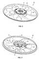
- FIG. 2is a top perspective view of the axial fan of the axial fan assembly of FIG. 1 .
- FIG. 3is a bottom perspective view of the axial fan of the axial fan assembly of FIG. 1 .
- FIG. 6is an enlarged, top view of a portion of the axial fan of the axial fan assembly of FIG. 1
- FIG. 7is an enlarged, cross-sectional view of a portion of the axial fan assembly of FIG. 1 , illustrating a downstream blockage spaced from the axial fan.
- FIG. 8is an enlarged view of the cross-section of the axial fan assembly of FIG. 7 , illustrating the spacing between the axial fan and the shroud.
- FIG. 10is a graph illustrating blade pitch and blade skew angle over the span of the axial fan of the axial fan assembly of FIG. 1 .
- FIG. 11is a graph illustrating blade rake over the span of the axial fan of the axial fan assembly of FIG. 1 .
- FIG. 1illustrates an axial fan assembly 10 coupled to a heat exchanger 14 , such as an automobile radiator.
- the axial fan assembly 10may be utilized in combination with the heat exchanger 14 in any of a number of different applications.
- the axial fan assembly 10includes a shroud 18 , a motor 22 coupled to the shroud 18 , and an axial fan 26 coupled to and driven by the motor 22 .
- the motor 22includes an output shaft 30 for driving the axial fan 26 about a central axis 34 of the output shaft 30 and the axial fan 26 .
- the axial fan assembly 10is coupled to the heat exchanger 14 in a “draw-through” configuration, such that the axial fan 26 draws an airflow through the heat exchanger 14 .
- the axial fan assembly 10may be coupled to the heat exchanger 14 in a “push-through” configuration, such that the axial fan 10 discharges an airflow through the heat exchanger 14 .
- Any of a number of different connectorsmay be utilized to couple the axial fan assembly 10 to the heat exchanger 14 .
- the shroud 18includes a mount 38 upon which the motor 22 is coupled.
- the mount 38is coupled to the outer portions of the shroud 18 by a plurality of canted vanes 42 , which redirect the airflow discharged by the axial fan 26 .
- an alternative construction of the axial fan assembly 10may utilize other support members, which do not substantially redirect the airflow discharged from the axial fan 26 , to couple the mount 38 to the outer portions of the shroud 18 .
- the motor 22may be coupled to the mount 38 using any of a number of different fasteners or other connecting devices.
- the shroud 18also includes a substantially annular outlet bell 46 positioned around the outer periphery of the axial fan 26 .
- a plurality of leakage stators 50are coupled to the outlet bell 46 and are arranged about the central axis 34 .
- the leakage stators 50reduce recirculation around the outer periphery of the axial fan 26 by disrupting or decreasing the tangential component of the recirculating airflow (i.e., the “pre-swirl”).
- an alternative construction of the axial fan assembly 10may utilize an outlet bell 46 and leakage stators 50 configured differently than those illustrated in FIG. 1 Further, yet another alternative construction of the axial fan assembly 10 may not include the outlet bell 46 or leakage stators 50 .
- the axial fan 26includes a central hub 54 , a plurality of blades 58 extending outwardly from the hub 54 , and a band 62 connecting the blades 58 .
- each blade 58includes a root portion or a root 66 adjacent and coupled to the hub 54 , and a tip portion or a tip 70 spaced outwardly from the root 66 and coupled to the band 62 .
- the radial distance between the central axis 34 and the tips 70 of the respective blades 58is defined as the maximum blade radius “R” of the axial fan 26 (see FIG.
- each blade 58is defined as the span of the blade “S.”
- the diameter of the blades 58is defined as the maximum blade diameter “D” and is equal to two times the blade radius “R.”
- Each blade 58also includes a leading edge 74 between the root 66 and the tip 70 , and a trailing edge 78 between the root 66 and the tip 70 .
- FIG. 4illustrates the leading and trailing edges 74 , 78 of the blades 58 relative to the clockwise-direction of rotation of the axial fan 26 , indicated by arrow “A.”
- the blades 58may be configured differently in accordance with a counter-clockwise direction of rotation of the axial fan 26 .
- each blade 58includes a pressure surface 86 (see FIGS. 2 and 4 ) and a suction surface 82 (see FIG. 3 ). The pressure and suction surfaces 86 , 82 give each blade 58 an airfoil shape, which allows the axial fan 26 to generate an airflow.
- a plurality of secondary blades 90are arranged about the central axis 34 and coupled to the inner periphery of the hub 54 to provide a cooling airflow over the motor 22 .
- the motor 22may include a motor housing 94 substantially enclosing the electrical components of the motor (see FIG. 1 ).
- the motor housing 94may include a plurality of apertures to allow the cooling airflow generated by the secondary blades 90 to pass through the housing 94 to cool the electrical components of the motor 22 .
- the motor housing 94may not include any apertures, and the cooling airflow generated by the secondary blades 90 may be directed solely over the housing 94 .
- the axial fan 26may not include the secondary blades 90 .
- FIG. 4several characteristics of the blades 58 vary over the span S. Particularly, these characteristics may be measured at discrete cylindrical blade sections corresponding with a radius “r” moving from the root 66 of the blade 58 to the tip 70 of the blade 58 .
- a blade section having radius “r”is thus defined at the intersection of the fan 26 with a cylinder having radius “r” and an axis colinear with the central axis 34 of the fan 26 .
- the blade section corresponding with the tip 70 of the blade 58has a radius “R” equal to the maximum radius of the blades 58 of the axial fan 26 .
- a blade section near the end of the span S(i.e., r/R ⁇ 1) is shown.
- the blade 58has a curvature.
- the extent of the curvature of the blade 58is measured by referencing a mean line 98 and a nose-tail line 102 of the blade 58 at the particular blade section.
- the mean line 98extends from the leading edge 74 to the trailing edge 78 of the blade 58 , half-way between the pressure surface 86 and the suction surface 82 of the blade 58 .
- the nose-tail line 102is a straight line extending between the leading edge 74 and the trailing edge 78 of the blade 58 , and intersecting the mean line 98 at the leading edge 74 and the trailing edge 78 of the blade 58 .
- Camberis a non-dimensional quantity that is a function of position along the nose-tail line 102 .
- camberis a function describing the perpendicular distance “D” from the nose-tail line 102 to the mean line 98 , divided by the length of the nose-tail line 102 , otherwise known as the blade “chord.”
- the larger the non-dimensional quantity of camberthe greater the curvature of the blade 58 .
- the pitch of the blades 58is a characteristic that generally governs the amount of static pressure generated by the blade 58 along its radial length. As is evident from the above equation, pitch is a dimensional quantity and is visualized as the axial distance theoretically traveled by the particular blade section at radius “r” through one shaft revolution, if rotating in a solid medium, akin to screw being threaded into a piece of wood.
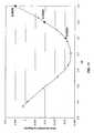
- FIG. 9illustrates blade pitch over the span S of the axial fan 26 .
- the X-axisrepresents the fraction “r/R” along the span S of a particular blade section
- the Y-axisrepresents a ratio of blade pitch to the average blade pitch of all the blade sections between the root 66 of the blade 58 and the tip 70 of the blade 58 .
- the curve illustrated in FIG. 9is normalized and is representative of both high-pitch and low-pitch axial fans 26 .
- the curve illustrated in FIG. 9is representative of axial fans 26 having different blade diameters D. Because the “average blade pitch” is merely a scalar, the shape of the curve representative of “blade pitch” is the same as that which is representative of “blade pitch/average blade pitch.”
- the ratio of blade pitch to average blade pitchdoes not decrease within the outer 20% of the blade radius R, or between 0.8 ⁇ r/R ⁇ 1. Additionally, the ratio of blade pitch to average blade pitch increases within the outer 20% of the blade radius R.
- the “blade pitch/average blade pitch” valueincreases by about 40% within the outer 20% of the blade radius R, from about 0.88 to about 1.22. However, in other constructions of the blade 58 the “blade pitch/average blade pitch” value may increase by at least about 5% within the outer 20% of the blade radius R.
- the “blade pitch/average blade pitch” valuemay increase by at least about 5% within the outer 20% of the blade radius R.
- the “blade pitch/average blade pitch” valueincreases continuously over the outer 10% of the blade radius R, or between 0.9 ⁇ r/R ⁇ 1. In other constructions of the blade 58 , the “blade pitch/average blade pitch” value may increase by about 30% to about 75% within the outer 20% of the blade radius R, while in yet other constructions of the blade 58 the “blade pitch/average blade pitch” value may increase by about 20% to about 60% within the outer 10% of the blade radius R.
- the tips 70 of the blades 58can develop an increasing static pressure to maintain high-velocity axial airflow at the band 62 , therefore improving efficiency of the axial fan 26 , despite the presence of radially-inward components of the inflow.
- the blades 58 of the axial fan 26are shaped having a varying skew angle “ ⁇ .”
- the skew angle ⁇ of the blade 58is measured at a particular blade section corresponding with radius “r,” with reference to the blade section corresponding with the root 66 of the blade 58 .
- a reference point 110is marked mid-chord of the blade section corresponding with the root 66 of the blade 58
- a reference line 114is drawn through the reference point 110 and the central axis 34 of the axial fan 26 .
- the reference line 114demarcates a “positive” skew angle ⁇ from a “negative” skew angle ⁇ .
- a positive skew angle ⁇indicates that the blade 58 is skewed in the direction of rotation of the axial fan 26
- a negative skew angle ⁇indicates that the blade 58 is skewed in an opposite direction as the direction of rotation of the axial fan 26 .
- FIG. 10illustrates blade pitch and skew angle ⁇ over the span S of the axial fan 26 .
- the X-axisrepresents the non-dimensional radius, or the fraction “r/R,” along the span S of a particular blade section
- the left side Y-axisrepresents a ratio of blade pitch to the axial fan diameter or blade diameter D
- the right side Y-axisrepresents the skew angle ⁇ with reference to the reference line 114 .
- the curve illustrated in FIG. 10is non-dimensional and is representative of axial fans 26 having different blade diameters D. Because the blade diameter D is merely a scalar, the shape of the curve representative of “blade pitch” is the same as that which is representative of “blade pitch/blade diameter D.”
- the blades 58define a decreasing skew angle ⁇ within the outer 20% of the blade radius R.
- the skew angle ⁇decreases within the range 0.8 ⁇ r/R ⁇ 1.
- the skew angle ⁇ of the blades 58continuously decreases over the outer 20% of the blade radius R.
- the skew angle ⁇decreases by about 12.75 degrees within the outer 20% of the blade radius R, from about (+)2.75 degrees to about ( ⁇ )9.98 degrees.
- the blades 58may be configured such that the skew angle ⁇ decreases more or less than about 12.75 degrees within the outer 20% of the blade radius R.
- the skew angle ⁇ of the blades 58should decrease by at least about 5 degrees within the outer 20% of the blade radius R.
- the blades 58 of the axial fan 26are shaped having a varying rake profile.
- blade rakeis measured as an axial offset “ ⁇ ” of a mid-chord point (e.g., point “P”) of a particular blade section corresponding with radius “r” with reference to a mid-chord point of the blade section corresponding with the root 66 of the blade 58 (approximated by reference line 124 ).
- the value of the axial offset ⁇is negative when the mid-chord point (e.g., point “P”) of the blade section corresponding with radius “r” is located upstream of the mid-chord point of the blade section corresponding with the root 66 of the blade 58 , while the value of the axial offset A is positive when the mid-chord point of the blade section corresponding with radius “r” is located downstream of the mid-chord point of the blade section corresponding with the root 66 of the blade 58 .
- the mid-chord pointe.g., point “P”
- FIG. 11illustrates blade rake over the span S of the axial fan 26 .
- the X-axisrepresents the non-dimensional radius, or the fraction “r/R,” along the span S of a particular blade section
- the Y-axisrepresents a ratio of blade rake to the axial fan diameter or blade diameter D.
- the curve illustrated in FIG. 11is non-dimensional and is representative of axial fans 26 having different blade diameters D. Because the blade diameter D is merely a scalar, the shape of the curve representative of “blade rake” is the same as that which is representative of “blade rake/blade diameter D.”
- the rake profile of the blades 58 over the outer 20% of the blade radius Ris adjusted according to the skew angle and pitch profiles, illustrated in FIG. 10 , to reduce the radially-inward and radially-outward components of surface normals extending from the pressure surface 86 of the blades 58 .
- forward-skewing the blades 58i.e., in the positive direction indicated in FIG. 6
- varying the rake profile of the blades 58yields surface normals, or rays extending perpendicularly from the pressure surface 86 of the blade 58 , having radially-inward components in addition to axial and tangential components.
- Rake 100 ⁇ % - Rake 90 ⁇ % D( Skew 90 ⁇ % - Skew 100 ⁇ % 360 ⁇ ° ⁇ Pitch 100 ⁇ % + Pitch 90 ⁇ % D ⁇ 2 ) ⁇ 0.004
- Rake 90 ⁇ % - Rake 80 ⁇ % D( Skew 80 ⁇ % - Skew 90 ⁇ % 360 ⁇ ° ⁇ Pitch 90 ⁇ % + Pitch 80 ⁇ % D ⁇ 2 ) ⁇ 0.004
- the blades 58may include different skew angle and pitch profiles over the outer 20% of the blade radius R, such that the resulting rake profile over the outer 20% of the blade radius R is different than the illustrated non-dimensional rake profile in FIG. 11 .
- the axial fan assembly 10is shown positioned relative to a schematically-illustrated downstream “blockage” 126 .
- a blockage 126may be a portion of the automobile engine, for example.
- the efficiency of the axial fan assembly 10is dependent in part upon the spacing of the band 62 from the outlet bell 46 and the leakage stators 50 , and upon the spacing between the outlet bell 46 and the blockage 126 .
- FIG. 8illustrates the spacing between the band 62 and the outlet bell 46 and the leakage stators 50 in one construction of the axial fan assembly 10 .
- the band 62includes an end surface 130 adjacent an axially-extending, radially-innermost surface 134 and an axially-extending, radially-outermost surface 138 .
- the outlet bell 46includes an end surface 142 adjacent a radially-innermost surface 146 .
- An axial gap “G 1 ”is measured between the respective end surfaces 130 , 142 of the band 62 and the outlet bell 46 .
- FIG. 8also illustrates a radial gap “G 2 ” measured between the axially-extending, radially-outermost surface 138 of the band 62 and the radially-innermost surface 146 of the outlet bell 46 .
- the axial gap G 1 and the radial gap G 2are determined with respect to the spacing (“L”) between the outlet bell 46 and the blockage 126 (see FIG. 7 ), the radius of the axially-extending, radially-innermost surface 134 of the band (“R band ”), the radius of the hub 54 (“R hub ”), and the radius of a radially-outermost surface of the outlet bell 150 (“R out ”).
- the axial gap G 1 and the radial gap G 2may be determined with respect to a “Blockage Factor” calculated according to the formula:
- BlockageFactorR band 2 - R hub 2 2 ⁇ L ⁇ R out
- a ratio of the axial gap G 1 to the blade diameter Dmay be about 0.01 to about 0.025.
- the ratio of the axial gap G 1 to blade diameter Dmay be about 0 to about 0.01.
- the axial gap G 1is formed by positioning the end surface 130 upstream of the end surface 142 .
- the axial gap G 1may be formed by positioning the end surface 130 downstream of the end surface 142 .
- These preferred axial gaps G 1in combination with the preferred profiles for pitch, skew angle ⁇ , and axial offset ⁇ (i.e., rake) illustrated in FIGS. 9-11 , can increase the overall efficiency of the axial fan assembly 10 by increasing the efficiency of the leakage stators 50 , while reducing pre-swirl and recirculation of the airflow between the band 62 and the outlet bell 46 .
- a ratio of the radial gap G 2 to blade diameter Dmay be about 0.01 to about 0.02.
- the radial gap G 2is formed by positioning the axially-extending, radially-outermost surface 138 radially inwardly of the radially-innermost surface 146 of the outlet bell 46 .
- the axial fan assembly 10incorporates a relatively constant static pressure rise over the span of the axial fan blades 58 with a large shroud area ratio and small fan-to-core spacing. This combination of features often yields relatively high inward-radial inflow velocities at the tips 70 of the fan blades 58 . Additionally, a relatively high static pressure rise near the tips 70 of the blades 58 increases the recirculation of airflow between the band 62 and the outlet bell 46 . This, in turn, increases the pre-swirl of the inflow to the tips 70 of the blades 58 . Relatively high radially-inward inflow velocities can lead to separation of airflow from the band 62 and outlet bell 46 .
- Increasing the pitch of the blades 58 within the outer 20% of the blade radius Radapts the tips 70 of the blades 58 to the relatively high inflow velocities.
- the resulting increase in inflow velocities and static pressure riseis sustained by raking the blades 58 within the outer 20% of the blade radius R to insure that pressure developed by the blades 58 is optimally aligned with the direction of airflow, radially spacing the band 62 and the outlet bell 46 within a particular range depending on the Blockage Factor to guard against wake-separation and unnecessary constriction, and axially spacing the band 62 and the outlet bell 46 within a particular range depending on the Blockage Factor to optimize the function of the leakage stators 50 to reduce pre-swirl and recirculation.
Landscapes
- Engineering & Computer Science (AREA)
- Mechanical Engineering (AREA)
- General Engineering & Computer Science (AREA)
- Physics & Mathematics (AREA)
- Fluid Mechanics (AREA)
- Thermal Sciences (AREA)
- Structures Of Non-Positive Displacement Pumps (AREA)
- Turbine Rotor Nozzle Sealing (AREA)
- Mechanical Operated Clutches (AREA)
Abstract
Description
Pitch=2πr tan β
Claims (20)
Priority Applications (1)
| Application Number | Priority Date | Filing Date | Title |
|---|---|---|---|
| US11/755,983US7794204B2 (en) | 2006-05-31 | 2007-05-31 | Axial fan assembly |
Applications Claiming Priority (2)
| Application Number | Priority Date | Filing Date | Title |
|---|---|---|---|
| US80357606P | 2006-05-31 | 2006-05-31 | |
| US11/755,983US7794204B2 (en) | 2006-05-31 | 2007-05-31 | Axial fan assembly |
Publications (2)
| Publication Number | Publication Date |
|---|---|
| US20070280829A1 US20070280829A1 (en) | 2007-12-06 |
| US7794204B2true US7794204B2 (en) | 2010-09-14 |
Family
ID=38430503
Family Applications (2)
| Application Number | Title | Priority Date | Filing Date |
|---|---|---|---|
| US11/755,983Active2029-06-13US7794204B2 (en) | 2006-05-31 | 2007-05-31 | Axial fan assembly |
| US11/755,988Active2029-05-05US7762769B2 (en) | 2006-05-31 | 2007-05-31 | Axial fan assembly |
Family Applications After (1)
| Application Number | Title | Priority Date | Filing Date |
|---|---|---|---|
| US11/755,988Active2029-05-05US7762769B2 (en) | 2006-05-31 | 2007-05-31 | Axial fan assembly |
Country Status (9)
| Country | Link |
|---|---|
| US (2) | US7794204B2 (en) |
| EP (2) | EP2029897B1 (en) |
| JP (1) | JP5097201B2 (en) |
| KR (1) | KR101018146B1 (en) |
| CN (1) | CN101535657B (en) |
| AT (2) | ATE444448T1 (en) |
| BR (1) | BRPI0711849B1 (en) |
| DE (2) | DE602007002588D1 (en) |
| WO (1) | WO2007140438A2 (en) |
Cited By (14)
| Publication number | Priority date | Publication date | Assignee | Title |
|---|---|---|---|---|
| US20110067845A1 (en)* | 2009-04-13 | 2011-03-24 | Alan Bishop | Fan shroud assembly |
| US20110211949A1 (en)* | 2010-02-26 | 2011-09-01 | Robert Bosch Gmbh | Free-tipped axial fan assembly |
| US8746186B2 (en)* | 2012-08-23 | 2014-06-10 | Briggs & Stratton Corporation | Rotating screen for centrifugal fan |
| US9551356B2 (en) | 2013-10-04 | 2017-01-24 | Caterpillar Inc. | Double bell mouth shroud |
| US9926832B2 (en) | 2015-04-24 | 2018-03-27 | Briggs & Stratton Corporation | Reverse fin cooling fan |
| US10167766B2 (en) | 2015-04-24 | 2019-01-01 | Briggs & Stratton Corporation | Reverse fin cooling fan |
| US10844868B2 (en) | 2015-04-15 | 2020-11-24 | Robert Bosch Gmbh | Free-tipped axial fan assembly |
| US10844770B2 (en)* | 2018-12-04 | 2020-11-24 | Brose Fahrzeugteile GmbH & Co. Kommanditgesellschaft, Würzburg | Cooling fan module |
| USD911512S1 (en) | 2018-01-31 | 2021-02-23 | Carrier Corporation | Axial flow fan |
| US11142038B2 (en) | 2017-12-18 | 2021-10-12 | Carrier Corporation | Labyrinth seal for fan assembly |
| US20220170469A1 (en)* | 2020-12-02 | 2022-06-02 | Robert Bosch Gmbh | Counter-Rotating Fan Assembly |
| US11598217B2 (en) | 2019-10-17 | 2023-03-07 | Dassault Systemes Simulia Corp. | Method for automatic calculation of axial cooling fan shroud circular opening size |
| US11835054B2 (en)* | 2019-10-17 | 2023-12-05 | Dassault Systemes Simulia Corp. | Method for automatic detection of axial cooling fan rotation direction |
| US11884128B2 (en) | 2017-12-18 | 2024-01-30 | Carrier Corporation | Fan stator construction to minimize axial depth |
Families Citing this family (31)
| Publication number | Priority date | Publication date | Assignee | Title |
|---|---|---|---|---|
| ATE444448T1 (en) | 2006-05-31 | 2009-10-15 | Bosch Gmbh Robert | AXIAL FAN ARRANGEMENT |
| JP2008267176A (en)* | 2007-04-17 | 2008-11-06 | Sony Corp | Axial flow fan device, housing, and electronic equipment |
| FR2950660B1 (en)* | 2009-09-29 | 2017-08-25 | Valeo Systemes Thermiques | PROPELLER, MOTOR COOLING DEVICE COMPRISING SUCH A PROPELLER, METHOD AND MOLD FOR MANUFACTURING THE SAME |
| US8157524B2 (en)* | 2009-12-03 | 2012-04-17 | Robert Bosch Gmbh | Axial flow fan with hub isolation slots |
| US8468826B2 (en)* | 2010-04-19 | 2013-06-25 | Honeywell International Inc. | Axial turbine wheel |
| US20110273038A1 (en)* | 2010-05-07 | 2011-11-10 | Robert Bosch Gmbh | Motor ring and splash shield arrangement for a fan assembly |
| US8091177B2 (en)* | 2010-05-13 | 2012-01-10 | Robert Bosch Gmbh | Axial-flow fan |
| KR101724294B1 (en)* | 2010-10-27 | 2017-04-07 | 엘지전자 주식회사 | Out door unit of air conditioner |
| US20120121410A1 (en)* | 2010-11-11 | 2012-05-17 | Wen-Hao Liu | Round axial fan with balancing structure |
| JP5413449B2 (en)* | 2011-12-28 | 2014-02-12 | ダイキン工業株式会社 | Axial fan |
| JP5549686B2 (en)* | 2012-01-12 | 2014-07-16 | 株式会社デンソー | Blower |
| DE202012000939U1 (en)* | 2012-01-28 | 2012-03-15 | Brose Fahrzeugteile GmbH & Co. Kommanditgesellschaft, Würzburg | Radiator fan of a motor vehicle |
| US9234521B2 (en)* | 2012-05-28 | 2016-01-12 | Asia Vital Components Co., Ltd. | Ring-type fan and impeller structure thereof |
| CN104903589B (en)* | 2013-01-11 | 2018-09-07 | 开利公司 | There is cover aerofoil fan using treated casing |
| US20160025104A1 (en)* | 2014-07-28 | 2016-01-28 | Asia Vital Components Co., Ltd. | Annular fan wiring structure |
| FR3033845B1 (en)* | 2015-03-19 | 2018-04-27 | Valeo Systemes Thermiques | AERODYNAMICALLY AND ACOUSTICALLY ENHANCED AUTOMOBILE FAN |
| US10400783B1 (en)* | 2015-07-01 | 2019-09-03 | Dometic Sweden Ab | Compact fan for a recreational vehicle |
| GB2545269B (en)* | 2015-12-11 | 2018-02-28 | Dyson Technology Ltd | An electric motor |
| CN108603512B (en)* | 2016-02-08 | 2021-03-12 | 罗伯特·博世有限公司 | Engine cooling fan shroud with unplugged outlets |
| TWD182168S (en)* | 2016-07-27 | 2017-04-01 | 鑫賀精密電子(東莞)有限公司; | fan |
| DK179200B1 (en)* | 2016-08-25 | 2018-01-29 | Dacs As | Improved wing for an axial flow fan |
| DE102017201331A1 (en) | 2017-01-27 | 2018-08-02 | BSH Hausgeräte GmbH | Blower for extractor and extractor fan |
| DE102017116352A1 (en)* | 2017-07-20 | 2019-01-24 | Brose Fahrzeugteile Gmbh & Co. Kg, Würzburg | Cooling fan module |
| USD860427S1 (en)* | 2017-09-18 | 2019-09-17 | Horton, Inc. | Ring fan |
| JP7116459B2 (en)* | 2017-10-05 | 2022-08-10 | 国立研究開発法人宇宙航空研究開発機構 | Ducted fan, multicopter, vertical take-off and landing aircraft, CPU cooling fan and radiator cooling fan |
| WO2021118208A1 (en)* | 2019-12-09 | 2021-06-17 | 엘지전자 주식회사 | Blower |
| DE102019220232A1 (en)* | 2019-12-19 | 2021-06-24 | Brose Fahrzeugteile SE & Co. Kommanditgesellschaft, Würzburg | Radiator fan |
| IT202100020606A1 (en)* | 2021-07-30 | 2023-01-30 | Johnson Electric Asti S R L | Cooling fan module for a vehicle |
| DE112022003963T5 (en)* | 2021-10-11 | 2024-07-04 | Milwaukee Electric Tool Corporation | BLOWER FOR A HANDHELD BLOWER |
| US12352275B2 (en)* | 2023-04-06 | 2025-07-08 | Techtronic Cordless Gp | Fan assembly |
| KR102808316B1 (en)* | 2023-07-05 | 2025-05-15 | 엘지전자 주식회사 | An outdoor unit of air conditioner |
Citations (39)
| Publication number | Priority date | Publication date | Assignee | Title |
|---|---|---|---|---|
| US4358245A (en) | 1980-09-18 | 1982-11-09 | Bolt Beranek And Newman Inc. | Low noise fan |
| US4569632A (en) | 1983-11-08 | 1986-02-11 | Airflow Research And Manufacturing Corp. | Back-skewed fan |
| US4684324A (en) | 1985-08-02 | 1987-08-04 | Gate S.P.A. | Axial fan, particularly for motor vehicles |
| US4930990A (en)* | 1989-09-15 | 1990-06-05 | Siemens-Bendix Automotive Electronics Limited | Quiet clutch fan blade |
| US5244347A (en) | 1991-10-11 | 1993-09-14 | Siemens Automotive Limited | High efficiency, low noise, axial flow fan |
| US5297931A (en)* | 1991-08-30 | 1994-03-29 | Airflow Research And Manufacturing Corporation | Forward skew fan with rake and chordwise camber corrections |
| US5393199A (en) | 1992-07-22 | 1995-02-28 | Valeo Thermique Moteur | Fan having a blade structure for reducing noise |
| WO1995006822A1 (en) | 1993-08-30 | 1995-03-09 | Airflow Research Manufacturing Corporation | Housing with recirculation control for use with banded axial-flow fans |
| US5489186A (en) | 1991-08-30 | 1996-02-06 | Airflow Research And Manufacturing Corp. | Housing with recirculation control for use with banded axial-flow fans |
| EP0704625A2 (en) | 1994-09-29 | 1996-04-03 | Valeo Thermique Moteur | A fan |
| US5520513A (en)* | 1990-03-07 | 1996-05-28 | Nippondenso Co., Ltd. | Fan apparatus |
| US5577888A (en) | 1995-06-23 | 1996-11-26 | Siemens Electric Limited | High efficiency, low-noise, axial fan assembly |
| US5582507A (en) | 1994-09-29 | 1996-12-10 | Valeo Thermique Moteur | Automotive fan structure |
| US5624234A (en) | 1994-11-18 | 1997-04-29 | Itt Automotive Electrical Systems, Inc. | Fan blade with curved planform and high-lift airfoil having bulbous leading edge |
| US5701854A (en) | 1994-10-26 | 1997-12-30 | Behr Gmbh & Co. | Axial fan for an internal combustion engine |
| US5730583A (en) | 1994-09-29 | 1998-03-24 | Valeo Thermique Moteur | Axial flow fan blade structure |
| US5769607A (en) | 1997-02-04 | 1998-06-23 | Itt Automotive Electrical Systems, Inc. | High-pumping, high-efficiency fan with forward-swept blades |
| US5906179A (en) | 1997-06-27 | 1999-05-25 | Siemens Canada Limited | High efficiency, low solidity, low weight, axial flow fan |
| US5961289A (en) | 1995-11-22 | 1999-10-05 | Deutsche Forshungsanstalt Fur Luft-Und Raumfahrt E.V. | Cooling axial flow fan with reduced noise levels caused by swept laminar and/or asymmetrically staggered blades |
| US6065937A (en) | 1998-02-03 | 2000-05-23 | Siemens Canada Limited | High efficiency, axial flow fan for use in an automotive cooling system |
| US6238184B1 (en) | 1998-03-30 | 2001-05-29 | Gate S.P.A. | Axial fan, particularly for motor vehicles |
| US6241474B1 (en) | 1998-12-30 | 2001-06-05 | Valeo Thermique Moteur | Axial flow fan |
| US6287078B1 (en) | 1998-12-31 | 2001-09-11 | Halla Climate Control Corp. | Axial flow fan |
| US6350104B1 (en) | 1998-07-28 | 2002-02-26 | Valeo Thermique Moteur | Fan blade |
| US6368061B1 (en) | 1999-11-30 | 2002-04-09 | Siemens Automotive, Inc. | High efficiency and low weight axial flow fan |
| US6375427B1 (en) | 2000-04-14 | 2002-04-23 | Borgwarner Inc. | Engine cooling fan having supporting vanes |
| US6398492B1 (en) | 1998-12-31 | 2002-06-04 | Halla Climate Control Corp. | Airflow guide stator vane for axial flow fan and shrouded axial flow fan assembly having such airflow guide stator vanes |
| US20030026699A1 (en) | 2000-11-08 | 2003-02-06 | Stairs Robert W. | High efficiency, inflow-adapted, axial-flow fan |
| US6554574B1 (en) | 1998-03-23 | 2003-04-29 | Spal S.R.L. | Axial flow fan |
| US6558123B1 (en) | 1998-03-23 | 2003-05-06 | Spal S.R.L. | Axial flow fan |
| US6595744B2 (en) | 2000-06-16 | 2003-07-22 | Robert Bosch Corporation | Automotive fan assembly with flared shroud and fan with conforming blade tips |
| US6872052B2 (en) | 2003-03-07 | 2005-03-29 | Siemens Vdo Automotive Inc. | High-flow low torque fan |
| US6908287B2 (en) | 2001-06-12 | 2005-06-21 | Halla Climate Control Corp. | Axial flow fan |
| WO2005066504A1 (en) | 2004-01-12 | 2005-07-21 | Siemens Vdo Automotive Inc. | Low pressure fan with high-flow |
| WO2005098213A1 (en) | 2004-04-05 | 2005-10-20 | Komatsu Ltd. | Cooling device |
| WO2005100797A1 (en) | 2004-04-05 | 2005-10-27 | Peugeot Citroen Automobiles Sa | Motor-driven fan for motor vehicles |
| WO2006006043A1 (en) | 2004-07-06 | 2006-01-19 | Spal Automotive S.R.L. | Axial fan |
| US20060067820A1 (en) | 2004-09-24 | 2006-03-30 | Yu Wang | Fan |
| US7189061B2 (en)* | 2004-09-30 | 2007-03-13 | Valeo Electrical Systems, Inc. | Cooling fan for vehicles |
Family Cites Families (4)
| Publication number | Priority date | Publication date | Assignee | Title |
|---|---|---|---|---|
| DK345883D0 (en)* | 1983-07-28 | 1983-07-28 | Nordisk Ventilator | axial |
| US4548548A (en)* | 1984-05-23 | 1985-10-22 | Airflow Research And Manufacturing Corp. | Fan and housing |
| KR100467331B1 (en)* | 1997-06-05 | 2005-04-08 | 한라공조주식회사 | Fan and fan-shroud assembly |
| ATE444448T1 (en) | 2006-05-31 | 2009-10-15 | Bosch Gmbh Robert | AXIAL FAN ARRANGEMENT |
- 2007
- 2007-05-31ATAT07010774Tpatent/ATE444448T1/ennot_activeIP Right Cessation
- 2007-05-31ATAT07811969Tpatent/ATE483916T1/ennot_activeIP Right Cessation
- 2007-05-31EPEP07811969Apatent/EP2029897B1/enactiveActive
- 2007-05-31WOPCT/US2007/070028patent/WO2007140438A2/enactiveApplication Filing
- 2007-05-31BRBRPI0711849Apatent/BRPI0711849B1/enactiveIP Right Grant
- 2007-05-31DEDE602007002588Tpatent/DE602007002588D1/enactiveActive
- 2007-05-31USUS11/755,983patent/US7794204B2/enactiveActive
- 2007-05-31KRKR1020087031930Apatent/KR101018146B1/enactiveActive
- 2007-05-31USUS11/755,988patent/US7762769B2/enactiveActive
- 2007-05-31CNCN200780028700XApatent/CN101535657B/enactiveActive
- 2007-05-31EPEP07010774Apatent/EP1862675B1/enactiveActive
- 2007-05-31DEDE602007009678Tpatent/DE602007009678D1/enactiveActive
- 2007-05-31JPJP2009513446Apatent/JP5097201B2/enactiveActive
Patent Citations (42)
| Publication number | Priority date | Publication date | Assignee | Title |
|---|---|---|---|---|
| US4358245A (en) | 1980-09-18 | 1982-11-09 | Bolt Beranek And Newman Inc. | Low noise fan |
| US4569632A (en) | 1983-11-08 | 1986-02-11 | Airflow Research And Manufacturing Corp. | Back-skewed fan |
| US4684324A (en) | 1985-08-02 | 1987-08-04 | Gate S.P.A. | Axial fan, particularly for motor vehicles |
| US4930990A (en)* | 1989-09-15 | 1990-06-05 | Siemens-Bendix Automotive Electronics Limited | Quiet clutch fan blade |
| US5520513A (en)* | 1990-03-07 | 1996-05-28 | Nippondenso Co., Ltd. | Fan apparatus |
| US5297931A (en)* | 1991-08-30 | 1994-03-29 | Airflow Research And Manufacturing Corporation | Forward skew fan with rake and chordwise camber corrections |
| US5489186A (en) | 1991-08-30 | 1996-02-06 | Airflow Research And Manufacturing Corp. | Housing with recirculation control for use with banded axial-flow fans |
| US5244347A (en) | 1991-10-11 | 1993-09-14 | Siemens Automotive Limited | High efficiency, low noise, axial flow fan |
| US5393199A (en) | 1992-07-22 | 1995-02-28 | Valeo Thermique Moteur | Fan having a blade structure for reducing noise |
| WO1995006822A1 (en) | 1993-08-30 | 1995-03-09 | Airflow Research Manufacturing Corporation | Housing with recirculation control for use with banded axial-flow fans |
| EP0704625A2 (en) | 1994-09-29 | 1996-04-03 | Valeo Thermique Moteur | A fan |
| US5582507A (en) | 1994-09-29 | 1996-12-10 | Valeo Thermique Moteur | Automotive fan structure |
| US5730583A (en) | 1994-09-29 | 1998-03-24 | Valeo Thermique Moteur | Axial flow fan blade structure |
| US5701854A (en) | 1994-10-26 | 1997-12-30 | Behr Gmbh & Co. | Axial fan for an internal combustion engine |
| US5624234A (en) | 1994-11-18 | 1997-04-29 | Itt Automotive Electrical Systems, Inc. | Fan blade with curved planform and high-lift airfoil having bulbous leading edge |
| US5577888A (en) | 1995-06-23 | 1996-11-26 | Siemens Electric Limited | High efficiency, low-noise, axial fan assembly |
| US5961289A (en) | 1995-11-22 | 1999-10-05 | Deutsche Forshungsanstalt Fur Luft-Und Raumfahrt E.V. | Cooling axial flow fan with reduced noise levels caused by swept laminar and/or asymmetrically staggered blades |
| US5769607A (en) | 1997-02-04 | 1998-06-23 | Itt Automotive Electrical Systems, Inc. | High-pumping, high-efficiency fan with forward-swept blades |
| US5906179A (en) | 1997-06-27 | 1999-05-25 | Siemens Canada Limited | High efficiency, low solidity, low weight, axial flow fan |
| US6065937A (en) | 1998-02-03 | 2000-05-23 | Siemens Canada Limited | High efficiency, axial flow fan for use in an automotive cooling system |
| US6554574B1 (en) | 1998-03-23 | 2003-04-29 | Spal S.R.L. | Axial flow fan |
| US6558123B1 (en) | 1998-03-23 | 2003-05-06 | Spal S.R.L. | Axial flow fan |
| US6238184B1 (en) | 1998-03-30 | 2001-05-29 | Gate S.P.A. | Axial fan, particularly for motor vehicles |
| US6350104B1 (en) | 1998-07-28 | 2002-02-26 | Valeo Thermique Moteur | Fan blade |
| US6241474B1 (en) | 1998-12-30 | 2001-06-05 | Valeo Thermique Moteur | Axial flow fan |
| US6398492B1 (en) | 1998-12-31 | 2002-06-04 | Halla Climate Control Corp. | Airflow guide stator vane for axial flow fan and shrouded axial flow fan assembly having such airflow guide stator vanes |
| US6287078B1 (en) | 1998-12-31 | 2001-09-11 | Halla Climate Control Corp. | Axial flow fan |
| US6368061B1 (en) | 1999-11-30 | 2002-04-09 | Siemens Automotive, Inc. | High efficiency and low weight axial flow fan |
| US6375427B1 (en) | 2000-04-14 | 2002-04-23 | Borgwarner Inc. | Engine cooling fan having supporting vanes |
| US6595744B2 (en) | 2000-06-16 | 2003-07-22 | Robert Bosch Corporation | Automotive fan assembly with flared shroud and fan with conforming blade tips |
| US20030026699A1 (en) | 2000-11-08 | 2003-02-06 | Stairs Robert W. | High efficiency, inflow-adapted, axial-flow fan |
| US6579063B2 (en) | 2000-11-08 | 2003-06-17 | Robert Bosch Corporation | High efficiency, inflow-adapted, axial-flow fan |
| US6908287B2 (en) | 2001-06-12 | 2005-06-21 | Halla Climate Control Corp. | Axial flow fan |
| US6872052B2 (en) | 2003-03-07 | 2005-03-29 | Siemens Vdo Automotive Inc. | High-flow low torque fan |
| WO2005066504A1 (en) | 2004-01-12 | 2005-07-21 | Siemens Vdo Automotive Inc. | Low pressure fan with high-flow |
| US20050249597A1 (en) | 2004-01-12 | 2005-11-10 | Siemens Vdo Automotive Inc. | Low pressure fan with high-flow |
| WO2005098213A1 (en) | 2004-04-05 | 2005-10-20 | Komatsu Ltd. | Cooling device |
| WO2005100797A1 (en) | 2004-04-05 | 2005-10-27 | Peugeot Citroen Automobiles Sa | Motor-driven fan for motor vehicles |
| GB2427899A (en) | 2004-04-05 | 2007-01-10 | Komatsu Mfg Co Ltd | Cooling device |
| WO2006006043A1 (en) | 2004-07-06 | 2006-01-19 | Spal Automotive S.R.L. | Axial fan |
| US20060067820A1 (en) | 2004-09-24 | 2006-03-30 | Yu Wang | Fan |
| US7189061B2 (en)* | 2004-09-30 | 2007-03-13 | Valeo Electrical Systems, Inc. | Cooling fan for vehicles |
Non-Patent Citations (1)
| Title |
|---|
| Stevens, William and Stairs, Robert W., Axial Fan Assembly, U.S. Appl. No. 11/755,988, filed May 31, 2007. |
Cited By (17)
| Publication number | Priority date | Publication date | Assignee | Title |
|---|---|---|---|---|
| US20110067845A1 (en)* | 2009-04-13 | 2011-03-24 | Alan Bishop | Fan shroud assembly |
| US20110211949A1 (en)* | 2010-02-26 | 2011-09-01 | Robert Bosch Gmbh | Free-tipped axial fan assembly |
| US9004860B2 (en) | 2010-02-26 | 2015-04-14 | Robert Bosch Gmbh | Free-tipped axial fan assembly |
| US8746186B2 (en)* | 2012-08-23 | 2014-06-10 | Briggs & Stratton Corporation | Rotating screen for centrifugal fan |
| US9551356B2 (en) | 2013-10-04 | 2017-01-24 | Caterpillar Inc. | Double bell mouth shroud |
| US11499564B2 (en) | 2015-04-15 | 2022-11-15 | Robert Bosch Gmbh | Free-tipped axial fan assembly |
| US10844868B2 (en) | 2015-04-15 | 2020-11-24 | Robert Bosch Gmbh | Free-tipped axial fan assembly |
| US10167766B2 (en) | 2015-04-24 | 2019-01-01 | Briggs & Stratton Corporation | Reverse fin cooling fan |
| US9926832B2 (en) | 2015-04-24 | 2018-03-27 | Briggs & Stratton Corporation | Reverse fin cooling fan |
| US11142038B2 (en) | 2017-12-18 | 2021-10-12 | Carrier Corporation | Labyrinth seal for fan assembly |
| US11884128B2 (en) | 2017-12-18 | 2024-01-30 | Carrier Corporation | Fan stator construction to minimize axial depth |
| USD911512S1 (en) | 2018-01-31 | 2021-02-23 | Carrier Corporation | Axial flow fan |
| USD1029234S1 (en) | 2018-01-31 | 2024-05-28 | Carrier Corporation | Axial flow fan |
| US10844770B2 (en)* | 2018-12-04 | 2020-11-24 | Brose Fahrzeugteile GmbH & Co. Kommanditgesellschaft, Würzburg | Cooling fan module |
| US11598217B2 (en) | 2019-10-17 | 2023-03-07 | Dassault Systemes Simulia Corp. | Method for automatic calculation of axial cooling fan shroud circular opening size |
| US11835054B2 (en)* | 2019-10-17 | 2023-12-05 | Dassault Systemes Simulia Corp. | Method for automatic detection of axial cooling fan rotation direction |
| US20220170469A1 (en)* | 2020-12-02 | 2022-06-02 | Robert Bosch Gmbh | Counter-Rotating Fan Assembly |
Also Published As
| Publication number | Publication date |
|---|---|
| CN101535657A (en) | 2009-09-16 |
| US20070280827A1 (en) | 2007-12-06 |
| ATE444448T1 (en) | 2009-10-15 |
| EP1862675B1 (en) | 2009-09-30 |
| ATE483916T1 (en) | 2010-10-15 |
| JP2009539033A (en) | 2009-11-12 |
| DE602007009678D1 (en) | 2010-11-18 |
| US20070280829A1 (en) | 2007-12-06 |
| EP1862675A2 (en) | 2007-12-05 |
| EP2029897A2 (en) | 2009-03-04 |
| EP1862675A3 (en) | 2008-01-02 |
| KR20090014308A (en) | 2009-02-09 |
| DE602007002588D1 (en) | 2009-11-12 |
| US7762769B2 (en) | 2010-07-27 |
| JP5097201B2 (en) | 2012-12-12 |
| BRPI0711849A2 (en) | 2011-12-13 |
| BRPI0711849B1 (en) | 2019-09-10 |
| CN101535657B (en) | 2013-06-05 |
| EP2029897B1 (en) | 2010-10-06 |
| KR101018146B1 (en) | 2011-02-28 |
| WO2007140438A2 (en) | 2007-12-06 |
| WO2007140438A3 (en) | 2008-01-24 |
Similar Documents
| Publication | Publication Date | Title |
|---|---|---|
| US7794204B2 (en) | Axial fan assembly | |
| US11506211B2 (en) | Counter-rotating fan | |
| AU2003207098B2 (en) | Fan | |
| US20050186070A1 (en) | Fan assembly and method | |
| US5393199A (en) | Fan having a blade structure for reducing noise | |
| US10731881B2 (en) | Fan coil unit with shrouded fan | |
| US10190601B2 (en) | Shrouded axial fan with casing treatment | |
| US7186080B2 (en) | Fan inlet and housing for a centrifugal blower whose impeller has forward curved fan blades | |
| CN110431311A (en) | Propeller fan | |
| EP1455095A1 (en) | Axial-flow fan | |
| EP2539591B1 (en) | Free-tipped axial fan assembly | |
| KR20020026623A (en) | Axial fan | |
| KR20020094183A (en) | Axial flow fan | |
| CN217129855U (en) | Axial flow fan and axial flow fan blade thereof | |
| US20240263635A1 (en) | Rotor and axial ventilator comprising an accessory axial fan |
Legal Events
| Date | Code | Title | Description |
|---|---|---|---|
| AS | Assignment | Owner name:ROBERT BOSCH LLP, ILLINOIS Free format text:ASSIGNMENT OF ASSIGNORS INTEREST;ASSIGNORS:STEVENS, WILLIAM;STAIRS, ROBERT W.;REEL/FRAME:019384/0081;SIGNING DATES FROM 20070509 TO 20070510 Owner name:ROBERT BOSCH GMBH, GERMANY Free format text:ASSIGNMENT OF ASSIGNORS INTEREST;ASSIGNORS:STEVENS, WILLIAM;STAIRS, ROBERT W.;REEL/FRAME:019384/0081;SIGNING DATES FROM 20070509 TO 20070510 Owner name:ROBERT BOSCH LLP, ILLINOIS Free format text:ASSIGNMENT OF ASSIGNORS INTEREST;ASSIGNORS:STEVENS, WILLIAM;STAIRS, ROBERT W.;SIGNING DATES FROM 20070509 TO 20070510;REEL/FRAME:019384/0081 Owner name:ROBERT BOSCH GMBH, GERMANY Free format text:ASSIGNMENT OF ASSIGNORS INTEREST;ASSIGNORS:STEVENS, WILLIAM;STAIRS, ROBERT W.;SIGNING DATES FROM 20070509 TO 20070510;REEL/FRAME:019384/0081 | |
| AS | Assignment | Owner name:ROBERT BOSCH LLC, ILLINOIS Free format text:CORRECTIVE ASSIGNMENT TO CORRECT THE FIRST NAMED ASSIGNEE PREVIOUSLY RECORDED ON REEL 019384 FRAME 0081;ASSIGNORS:STEVENS, WILLIAM;STAIRS, ROBERT W.;REEL/FRAME:019507/0824;SIGNING DATES FROM 20070509 TO 20070510 Owner name:ROBERT BOSCH GMBH, GERMANY Free format text:CORRECTIVE ASSIGNMENT TO CORRECT THE FIRST NAMED ASSIGNEE PREVIOUSLY RECORDED ON REEL 019384 FRAME 0081;ASSIGNORS:STEVENS, WILLIAM;STAIRS, ROBERT W.;REEL/FRAME:019507/0824;SIGNING DATES FROM 20070509 TO 20070510 Owner name:ROBERT BOSCH LLC, ILLINOIS Free format text:CORRECTIVE ASSIGNMENT TO CORRECT THE FIRST NAMED ASSIGNEE PREVIOUSLY RECORDED ON REEL 019384 FRAME 0081. ASSIGNOR(S) HEREBY CONFIRMS THE FIRST NAMED ASSIGNEE NAME SHOULD BE ROBERT BOSCH LLC;ASSIGNORS:STEVENS, WILLIAM;STAIRS, ROBERT W.;SIGNING DATES FROM 20070509 TO 20070510;REEL/FRAME:019507/0824 Owner name:ROBERT BOSCH GMBH, GERMANY Free format text:CORRECTIVE ASSIGNMENT TO CORRECT THE FIRST NAMED ASSIGNEE PREVIOUSLY RECORDED ON REEL 019384 FRAME 0081. ASSIGNOR(S) HEREBY CONFIRMS THE FIRST NAMED ASSIGNEE NAME SHOULD BE ROBERT BOSCH LLC;ASSIGNORS:STEVENS, WILLIAM;STAIRS, ROBERT W.;SIGNING DATES FROM 20070509 TO 20070510;REEL/FRAME:019507/0824 | |
| STCF | Information on status: patent grant | Free format text:PATENTED CASE | |
| FPAY | Fee payment | Year of fee payment:4 | |
| MAFP | Maintenance fee payment | Free format text:PAYMENT OF MAINTENANCE FEE, 8TH YEAR, LARGE ENTITY (ORIGINAL EVENT CODE: M1552) Year of fee payment:8 | |
| MAFP | Maintenance fee payment | Free format text:PAYMENT OF MAINTENANCE FEE, 12TH YEAR, LARGE ENTITY (ORIGINAL EVENT CODE: M1553); ENTITY STATUS OF PATENT OWNER: LARGE ENTITY Year of fee payment:12 |