US7794181B2 - Mine roof and rib support device - Google Patents
Mine roof and rib support deviceDownload PDFInfo
- Publication number
- US7794181B2 US7794181B2US12/023,195US2319508AUS7794181B2US 7794181 B2US7794181 B2US 7794181B2US 2319508 AUS2319508 AUS 2319508AUS 7794181 B2US7794181 B2US 7794181B2
- Authority
- US
- United States
- Prior art keywords
- roof
- rib
- support arm
- support
- mine
- Prior art date
- Legal status (The legal status is an assumption and is not a legal conclusion. Google has not performed a legal analysis and makes no representation as to the accuracy of the status listed.)
- Active, expires
Links
Images


Classifications
- E—FIXED CONSTRUCTIONS
- E21—EARTH OR ROCK DRILLING; MINING
- E21D—SHAFTS; TUNNELS; GALLERIES; LARGE UNDERGROUND CHAMBERS
- E21D11/00—Lining tunnels, galleries or other underground cavities, e.g. large underground chambers; Linings therefor; Making such linings in situ, e.g. by assembling
- E21D11/006—Lining anchored in the rock
- E—FIXED CONSTRUCTIONS
- E21—EARTH OR ROCK DRILLING; MINING
- E21D—SHAFTS; TUNNELS; GALLERIES; LARGE UNDERGROUND CHAMBERS
- E21D11/00—Lining tunnels, galleries or other underground cavities, e.g. large underground chambers; Linings therefor; Making such linings in situ, e.g. by assembling
- E21D11/14—Lining predominantly with metal
- E21D11/34—Joints between vertical props and horizontal top bars
Definitions
- the support memberrelates generally to mine surface control, and more particularly to a mine roof and rib support with a roof support arm and a rib support arm which simultaneously support the mine roof and mine rib.
- Mine roof and rib supportsare commonly used in underground mining, excavating, and tunneling operations to support and control the overhead and lateral rock strata.
- a series of bore holescan be drilled into the mine roof or rib, a mine roof bolt can be installed in the bore hole, a channel, bearing plate, or mat can be positioned between the end of the mine roof bolt and the mine roof or rib, and the mine roof bolt can anchored in the bore hole and tensioned such that the mine roof bolt and channel, bearing plate, or mat exert a compressive force upon the mine roof and rib to prevent deterioration of the overhead and lateral rock strata.
- An embodiment of the mine roof and rib support devicecan generally comprise a support member having a roof support arm and a rib support arm, the roof support arm is provided at an angle to the rib support arm, and an aperture through the support member is provided for operatively receiving a mine roof bolt.
- the aperturecan be located adjacent a junction between, or an intersection of, the roof support arm and the rib support arm.
- the support membercan further comprise a flange provided on one, or both, of the roof support arm and the rib support arm, wherein the flange projects toward the mine roof and/or rib, respectively.
- the support membercan be made from a metal channel having a C-shaped cross-section, and the metal channel can be bent to form each of the roof and rib support arms.
- the angle between the roof and rib support armscan generally be about 90 degrees, to generally correspond to usual angle between the mine roof and the mine rib, but the angle can be different if needed.
- the flangescan be bent from the distal ends of each of the roof and rib support arms to hold the mesh that can commonly be provided between the support arm and the mine roof and/or rib.
- the mine roof and rib support devicecan further comprise a bearing plate having an upper edge and a lower edge, a through-hole provided between said upper and lower edges, and wherein said upper and lower edges are positioned in abutment with said roof support arm and said rib support arm, respectively, when the through-hole is operatively aligned with the aperture in the support member for installation of a roof bolt through each of the bearing plate and the support member, such that the upper and lower edges apply force to the roof and rib support arms, respectively, when force is applied to the bearing plate by installation of the roof bolt.
- the head of the mine roof bolt, or tensioning nutcan be torqued against the bearing plate such that the upper and lower edges of the bearing plate simultaneously exert force on each of the roof support arm and the rib support arm.
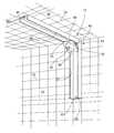
- FIG. 1is a perspective view of an embodiment of a mine roof and rib support device.
- FIG. 2is a front view illustrating embodiments of mine roof and rib support devices installed at the intersection of the mine roof and opposite sides/ribs of a mine work area.
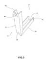
- FIG. 3is a perspective view of an embodiment of a support member of the mine roof and rib support device.
- FIG. 4is a front view of the support member shown in FIG. 3 .
- FIG. 5is a side view of the support member in shown FIG. 4 .
- FIG. 6is a bottom view of the support member in shown FIG. 4 .
- FIGS. 1 and 2a perspective view of an embodiment of a mine roof and rib support device 10 is shown in FIGS. 1 and 2 , which can generally comprise a support member 15 having a roof support arm 20 and a rib support arm 25 , wherein the roof support arm 20 is provided at an angle to the rib support arm 25 , and an aperture 30 (shown best in FIG. 3 ) through the support member for receiving a mine roof bolt 35 , the aperture located adjacent a junction between, or an intersection of, the roof support arm 20 and the rib support arm 25 .
- the support member 15can further comprise a flange 45 provided on one or both of the roof support arm 20 and the rib support arm 25 , wherein the flange 45 projects toward the mine roof 50 or rib 55 .
- flanges 45 , 47are provided at distal ends 50 , 65 of both the roof support arm 20 and the rib support arm 25 .
- the angle ⁇ between the roof 20 and rib 25 support armscan generally be about 90 degrees, since the angle ⁇ between the mine roof 50 and mine rib 55 is typically about 90 degrees. However, the angle ⁇ between the arms 20 , 25 can vary as needed, or desired, depending upon the angle between the mine roof 50 and the rib 55 . Moreover, the angle ⁇ between the mine roof 50 and rib 55 may not be exactly 90 degrees, and the mine roof 50 and/or rib 55 may likely not be perfectly flat. Thus, embodiments of the support member 15 can be sufficiently flexible to compensate for variations in the angle ⁇ of the roof 50 and rib 55 , and/or variations due to non-planar surfaces of the roof 50 and/or rib 55 .
- the flanges 45 , 47 at the ends of the roof 20 and rib 25 support armscan be bent from the distal ends 60 , 65 of each of the roof 20 and rib 25 support arms.
- portions of the distal ends 60 , 65 of each arm 20 , 25can be cut away to leave a tab, or extension, which can be bent to form the flanges 45 , 47 .
- the flanges 45 , 47can be bent toward the roof 50 , or rib 55 , as the flanges 45 , 47 are intended to hold a mat, e.g., a metal mesh 70 , in cases where such mesh 70 is used in combination with the roof support arm 20 and/or rib support arm 25 .
- Embodiments of the mine roof and rib support device 10can further comprise a bearing plate 75 having an upper edge 80 and a lower edge 85 , and a through-hole provided between the upper 80 and lower edges 85 through which the roof bolt 35 is installed.
- the bearing plate 75can be positioned adjacent the support member 15 such that the upper 80 and lower edges 85 of the bearing plate 75 are positioned in abutment with the roof 20 and rib 25 support arms, respectively.
- the through-hole in the bearing plate 75is operatively aligned with the aperture 30 in the support member 15 for installation of a roof bolt 35 therethrough, the upper 80 and lower 85 edges will apply force to the roof 20 and rib 25 support arms, respectively, when force is applied to the bearing plate 75 by installation of the roof bolt 35 .
- the roof bolt 35can be installed at a 45 degree angle, but could be installed at a different angle if desired.
- a compressive loadis applied to the bearing plate.
- the compressive loadis distributed throughout the edges of the bearing plate.
- the compressive loadis transmitted from the edges of the bearing plate to the roof support arm and the rib support arm, respectively, to compress the support arms against the roof and rib of the mine tunnel.
- the compressive forcescause the roof support arm to exert pressure against the mine roof and the rib support arm to exert pressure against the mine rib.
- FIG. 2is a plan view illustrating how the mine roof and rib support device 10 may be installed at each side of the mine tunnel. Because the bearing plate 75 can distribute the force from the roof bolt 35 to each of the roof 20 and rib 25 support arms, a single roof bolt 35 can be used for each support member 15 to simultaneously provide support for both the mine roof 50 and the mine rib 55 .
- the arrows 90 , 95 in the drawingshow the force vectors created by torquing the roof bolt 35 against the bearing plate 75 .
- FIGS. 3 through 6illustrate further details of the support member 15 , including the back surface of the support member shown in FIG. 3 .
- the support member 15can be made from a metal channel having a C-shaped cross-section.
- the metal channelcan be bent to form each of the roof 20 and rib 25 support arms.
- Each arm 20 , 25can generally be the same length, but each arm 20 , 25 could have a different length if desired.
- Certain embodiments of the support member 15can be made from standard four (4) inch “C” channel steel with 1 ⁇ 4 inch back wall thickness.
- the side walls of the channelcan be split, or notched, adjacent the bend line, i.e., where the channel will be bent to form the roof 20 and rib 25 support arms at generally 90 degrees to each other.
- the notchfacilitates not only bending the channel to form the roof 20 and rib 25 support arms, but also permits the arms 20 , 25 some freedom of movement away from each other when the support member 15 is bolted to the mine roof 50 .
- the bearing plate 75will provide the support, similar to a brace, to resist movement of the roof 20 and rib 25 support arms towards each other subsequent to installation of the roof bolt 35 .
- the channelcan be heated to facilitate the bending process.
- One manner of creating the flanges 45 , 47is to cut tabs at the distal end 60 , 65 , typically of both the roof 20 and rib 25 support arms, and then bend the tabs outwardly, away from the back of the channel, i.e., towards the mine roof/rib 50 / 55 , to form the flanges, 45 , 47 to engage the mesh 70 that is commonly disposed over the mine roof/rib 50 , 55 , under the support member 15 .
- the dimensions corresponding to the reference characters in FIGS. 4 through 6can be, for example, as follows:
- the exemplary embodiments showncan comprise an elongated metal structural support member having a C-shaped cross-section that will be typically be bent at an angle of about 90 degrees as described herein.
- This depictionis not intended to limit the various possible embodiments.
- the roof 20 and rib 25 support armsneed not be bent from a single length of material, and could instead be two separate pieces of material which are, e.g., welded together.
- the term “upwardly”shall refer to a direction with respect to a mine passageway which is oriented generally along the direction extending from the mine floor to the mine roof
- the term “downwardly”shall refer to a direction with respect to a mine passageway which is oriented generally along the direction extending from the mine roof to the mine floor
- the term “outwardly”shall refer to an orientation generally in transverse direction extending from the walls of the passageway to the mine passageway central longitudinal axis
- the term “inwardly”shall refer to an orientation generally in transverse direction extending from the central longitudinal axis of the mine passageway to the walls of the passageway.
Landscapes
- Engineering & Computer Science (AREA)
- Mining & Mineral Resources (AREA)
- Architecture (AREA)
- Civil Engineering (AREA)
- Structural Engineering (AREA)
- Life Sciences & Earth Sciences (AREA)
- General Life Sciences & Earth Sciences (AREA)
- Geochemistry & Mineralogy (AREA)
- Geology (AREA)
- Roof Covering Using Slabs Or Stiff Sheets (AREA)
Abstract
Description
- A=24 inches
- B=24 inches
- C=4 inches
- D=1.5 inches
- E=1.5 inches
- F=0.65 inches
Claims (10)
Priority Applications (2)
| Application Number | Priority Date | Filing Date | Title |
|---|---|---|---|
| US12/023,195US7794181B2 (en) | 2007-11-19 | 2008-01-31 | Mine roof and rib support device |
| US12/547,904US8197160B2 (en) | 2007-11-19 | 2009-08-26 | Mine roof and rib support with reinforced channel |
Applications Claiming Priority (2)
| Application Number | Priority Date | Filing Date | Title |
|---|---|---|---|
| US98888907P | 2007-11-19 | 2007-11-19 | |
| US12/023,195US7794181B2 (en) | 2007-11-19 | 2008-01-31 | Mine roof and rib support device |
Related Child Applications (1)
| Application Number | Title | Priority Date | Filing Date |
|---|---|---|---|
| US12/547,904Continuation-In-PartUS8197160B2 (en) | 2007-11-19 | 2009-08-26 | Mine roof and rib support with reinforced channel |
Publications (2)
| Publication Number | Publication Date |
|---|---|
| US20090285641A1 US20090285641A1 (en) | 2009-11-19 |
| US7794181B2true US7794181B2 (en) | 2010-09-14 |
Family
ID=41316321
Family Applications (1)
| Application Number | Title | Priority Date | Filing Date |
|---|---|---|---|
| US12/023,195Active2028-05-22US7794181B2 (en) | 2007-11-19 | 2008-01-31 | Mine roof and rib support device |
Country Status (1)
| Country | Link |
|---|---|
| US (1) | US7794181B2 (en) |
Cited By (4)
| Publication number | Priority date | Publication date | Assignee | Title |
|---|---|---|---|---|
| US20100054870A1 (en)* | 2007-11-19 | 2010-03-04 | Jennmar Corporation | Mine roof and rib support with reinforced channel |
| US20110250024A1 (en)* | 2010-04-12 | 2011-10-13 | Fci Holdings Delaware Inc. | Mine Roof and Rib Support with Vertical Bolt |
| US10151202B2 (en) | 2015-02-13 | 2018-12-11 | Fci Holdings Delaware, Inc. | Rib strap |
| US10247001B2 (en)* | 2016-01-29 | 2019-04-02 | China University Of Mining And Technology | Anti-spalling blocking bar for large cross-section coal gallery excavation work surface and supporting method |
Families Citing this family (2)
| Publication number | Priority date | Publication date | Assignee | Title |
|---|---|---|---|---|
| CN102619362A (en)* | 2011-01-28 | 2012-08-01 | 柳忠林 | Large-span and large-load pre-stress groove-shaped composite slab serving as top plate of basement |
| CN102146802A (en)* | 2011-02-20 | 2011-08-10 | 李明 | Front exploring beam for heading surface anchor rod support |
Citations (36)
| Publication number | Priority date | Publication date | Assignee | Title |
|---|---|---|---|---|
| US1797925A (en) | 1929-05-31 | 1931-03-24 | Kawneer Co | Store-front construction |
| US1946733A (en) | 1931-04-20 | 1934-02-13 | Archibald H Davis | Combination universal corner, reverse, and division bar |
| US2027882A (en) | 1933-12-07 | 1936-01-14 | Rostone Inc | Building construction |
| US2317634A (en) | 1940-01-13 | 1943-04-27 | Anders C Olsen | Building construction |
| US2641029A (en) | 1950-02-24 | 1953-06-09 | Fred H Trimmer | Coupling means and trim for laminated building units |
| US2742776A (en) | 1951-03-23 | 1956-04-24 | Allied Chem & Dye Corp | Building wall structure |
| US3003600A (en)* | 1958-04-10 | 1961-10-10 | James A Mackenzie | Constructional element |
| US3103025A (en) | 1958-12-03 | 1963-09-10 | Kaiser Aluminium Chem Corp | Structural unit |
| US3415064A (en)* | 1966-04-22 | 1968-12-10 | Talobre Joseph Antoine | Supporting device for rock walls |
| US3485405A (en) | 1968-07-05 | 1969-12-23 | Us Plywood Champ Papers Inc | Frame-structure for container |
| US3543463A (en) | 1967-03-16 | 1970-12-01 | Henry Cannon | Building corner construction |
| US3572787A (en) | 1969-10-08 | 1971-03-30 | Gerald L Timmerman | Knockdown joint construction for furniture frames and other structures |
| US3587205A (en) | 1968-10-29 | 1971-06-28 | Joseph Henry Gartside | Buildings |
| US3928716A (en)* | 1973-12-13 | 1975-12-23 | Louis Marrero | Electrical outlet box assembly |
| US4008547A (en) | 1975-08-11 | 1977-02-22 | Frederick Katzman | In-ground swimming pool |
| US4325657A (en)* | 1979-12-05 | 1982-04-20 | Elders G W | Roof support pin |
| US4456405A (en) | 1982-12-13 | 1984-06-26 | Alex Galis | Mine roof truss assembly and associated method |
| US4498816A (en)* | 1983-08-25 | 1985-02-12 | United States Steel Corporation | Mine roof support system |
| US4513554A (en) | 1982-12-27 | 1985-04-30 | Lawrence Brothers, Inc. | Barn door framing system |
| US4630974A (en) | 1985-03-13 | 1986-12-23 | Price & Adams | Roof support system for a mine and method for providing the same |
| US4699547A (en)* | 1985-03-15 | 1987-10-13 | Seegmiller Ben L | Mine truss structures and method |
| US4775266A (en) | 1986-12-22 | 1988-10-04 | Seegmiller Ben L | Structure and method for deterring cutter roof failure |
| US4949929A (en)* | 1989-03-27 | 1990-08-21 | Kesselman Marcia E | Adjustable L-shaped mounting bracket |
| US4960348A (en) | 1988-12-08 | 1990-10-02 | Seegmiller Ben L | Truss systems, components and methods for trussing arched mine roofs |
| US4987719A (en) | 1988-12-29 | 1991-01-29 | Goodson Jr Albert A | Reinforced concrete building construction and method of forming same |
| US5292209A (en) | 1993-05-14 | 1994-03-08 | Jennmar Corporation | Bearing plate |
| US5385433A (en) | 1993-05-14 | 1995-01-31 | Jennmar Corporation | Bearing plate |
| US5755535A (en)* | 1996-08-19 | 1998-05-26 | Triad Support Systems, Inc. | Mine roof truss system and related installation method |
| US5758465A (en)* | 1997-01-23 | 1998-06-02 | Logue; Patrick J. | Clip and method for securing a rod to a ceiling |
| US6131361A (en)* | 1998-03-04 | 2000-10-17 | Murphy; James T. | Displaceable support bracket for drywall panel installation |
| EP1081393A1 (en) | 1999-09-06 | 2001-03-07 | Inventio Ag | Coupling member for connecting panels |
| US6250041B1 (en) | 1997-09-15 | 2001-06-26 | Bhp Steel (Jla) Pty Ltd. | Hold down bracket |
| US6612087B2 (en)* | 2000-11-29 | 2003-09-02 | The Steel Network, Inc. | Building member connector allowing bi-directional relative movement |
| JP2006065921A (en) | 2004-08-25 | 2006-03-09 | Roland Corp | Process sequence editing program and device |
| US20060053714A1 (en) | 2004-08-17 | 2006-03-16 | Pryor Steven E | Rotating concentric holdown |
| US20080283702A1 (en)* | 2007-05-14 | 2008-11-20 | Timothy Dewayne Ikerd | Structural forged steel angled L-shaped brackets and steel joining plates for effecting the bolted connecting between various main structural supports a horizontal beam, the horizontal joist members, the horizontal rim joist members and a column in a lumber frame structure |
- 2008
- 2008-01-31USUS12/023,195patent/US7794181B2/enactiveActive
Patent Citations (37)
| Publication number | Priority date | Publication date | Assignee | Title |
|---|---|---|---|---|
| US1797925A (en) | 1929-05-31 | 1931-03-24 | Kawneer Co | Store-front construction |
| US1946733A (en) | 1931-04-20 | 1934-02-13 | Archibald H Davis | Combination universal corner, reverse, and division bar |
| US2027882A (en) | 1933-12-07 | 1936-01-14 | Rostone Inc | Building construction |
| US2317634A (en) | 1940-01-13 | 1943-04-27 | Anders C Olsen | Building construction |
| US2641029A (en) | 1950-02-24 | 1953-06-09 | Fred H Trimmer | Coupling means and trim for laminated building units |
| US2742776A (en) | 1951-03-23 | 1956-04-24 | Allied Chem & Dye Corp | Building wall structure |
| US3003600A (en)* | 1958-04-10 | 1961-10-10 | James A Mackenzie | Constructional element |
| US3103025A (en) | 1958-12-03 | 1963-09-10 | Kaiser Aluminium Chem Corp | Structural unit |
| US3415064A (en)* | 1966-04-22 | 1968-12-10 | Talobre Joseph Antoine | Supporting device for rock walls |
| US3543463A (en) | 1967-03-16 | 1970-12-01 | Henry Cannon | Building corner construction |
| US3485405A (en) | 1968-07-05 | 1969-12-23 | Us Plywood Champ Papers Inc | Frame-structure for container |
| US3587205A (en) | 1968-10-29 | 1971-06-28 | Joseph Henry Gartside | Buildings |
| US3572787A (en) | 1969-10-08 | 1971-03-30 | Gerald L Timmerman | Knockdown joint construction for furniture frames and other structures |
| US3928716A (en)* | 1973-12-13 | 1975-12-23 | Louis Marrero | Electrical outlet box assembly |
| US4008547A (en) | 1975-08-11 | 1977-02-22 | Frederick Katzman | In-ground swimming pool |
| US4325657A (en)* | 1979-12-05 | 1982-04-20 | Elders G W | Roof support pin |
| US4456405A (en) | 1982-12-13 | 1984-06-26 | Alex Galis | Mine roof truss assembly and associated method |
| US4513554A (en) | 1982-12-27 | 1985-04-30 | Lawrence Brothers, Inc. | Barn door framing system |
| US4498816A (en)* | 1983-08-25 | 1985-02-12 | United States Steel Corporation | Mine roof support system |
| US4630974A (en) | 1985-03-13 | 1986-12-23 | Price & Adams | Roof support system for a mine and method for providing the same |
| US4699547A (en)* | 1985-03-15 | 1987-10-13 | Seegmiller Ben L | Mine truss structures and method |
| US4775266A (en) | 1986-12-22 | 1988-10-04 | Seegmiller Ben L | Structure and method for deterring cutter roof failure |
| US4960348A (en) | 1988-12-08 | 1990-10-02 | Seegmiller Ben L | Truss systems, components and methods for trussing arched mine roofs |
| US4987719A (en) | 1988-12-29 | 1991-01-29 | Goodson Jr Albert A | Reinforced concrete building construction and method of forming same |
| US4949929A (en)* | 1989-03-27 | 1990-08-21 | Kesselman Marcia E | Adjustable L-shaped mounting bracket |
| US5385433A (en) | 1993-05-14 | 1995-01-31 | Jennmar Corporation | Bearing plate |
| US5292209A (en) | 1993-05-14 | 1994-03-08 | Jennmar Corporation | Bearing plate |
| USRE35902E (en) | 1993-05-14 | 1998-09-22 | Jennmar Corporation | Bearing plate |
| US5755535A (en)* | 1996-08-19 | 1998-05-26 | Triad Support Systems, Inc. | Mine roof truss system and related installation method |
| US5758465A (en)* | 1997-01-23 | 1998-06-02 | Logue; Patrick J. | Clip and method for securing a rod to a ceiling |
| US6250041B1 (en) | 1997-09-15 | 2001-06-26 | Bhp Steel (Jla) Pty Ltd. | Hold down bracket |
| US6131361A (en)* | 1998-03-04 | 2000-10-17 | Murphy; James T. | Displaceable support bracket for drywall panel installation |
| EP1081393A1 (en) | 1999-09-06 | 2001-03-07 | Inventio Ag | Coupling member for connecting panels |
| US6612087B2 (en)* | 2000-11-29 | 2003-09-02 | The Steel Network, Inc. | Building member connector allowing bi-directional relative movement |
| US20060053714A1 (en) | 2004-08-17 | 2006-03-16 | Pryor Steven E | Rotating concentric holdown |
| JP2006065921A (en) | 2004-08-25 | 2006-03-09 | Roland Corp | Process sequence editing program and device |
| US20080283702A1 (en)* | 2007-05-14 | 2008-11-20 | Timothy Dewayne Ikerd | Structural forged steel angled L-shaped brackets and steel joining plates for effecting the bolted connecting between various main structural supports a horizontal beam, the horizontal joist members, the horizontal rim joist members and a column in a lumber frame structure |
Cited By (5)
| Publication number | Priority date | Publication date | Assignee | Title |
|---|---|---|---|---|
| US20100054870A1 (en)* | 2007-11-19 | 2010-03-04 | Jennmar Corporation | Mine roof and rib support with reinforced channel |
| US8197160B2 (en)* | 2007-11-19 | 2012-06-12 | Fci Holdings Delaware, Inc. | Mine roof and rib support with reinforced channel |
| US20110250024A1 (en)* | 2010-04-12 | 2011-10-13 | Fci Holdings Delaware Inc. | Mine Roof and Rib Support with Vertical Bolt |
| US10151202B2 (en) | 2015-02-13 | 2018-12-11 | Fci Holdings Delaware, Inc. | Rib strap |
| US10247001B2 (en)* | 2016-01-29 | 2019-04-02 | China University Of Mining And Technology | Anti-spalling blocking bar for large cross-section coal gallery excavation work surface and supporting method |
Also Published As
| Publication number | Publication date |
|---|---|
| US20090285641A1 (en) | 2009-11-19 |
Similar Documents
| Publication | Publication Date | Title |
|---|---|---|
| US7794181B2 (en) | Mine roof and rib support device | |
| US5466095A (en) | Underground support system and method of support | |
| US8197160B2 (en) | Mine roof and rib support with reinforced channel | |
| KR20120104205A (en) | Structural reinforcement | |
| US6357190B1 (en) | Wall bracing method and system therefor | |
| US20110044770A1 (en) | Mesh system | |
| KR102077421B1 (en) | Furring strip having groove filling bolt and construction method of the same | |
| US4498816A (en) | Mine roof support system | |
| KR101500144B1 (en) | Arched wider width wale and wale structure by using of it | |
| KR102631555B1 (en) | Fastening member for installation of finishing panel and insulation panel and finishing panel and insulation panel system using the same | |
| US4274762A (en) | Prestressed rock truss | |
| US4091628A (en) | Prestressed elastic arched mine roof support | |
| US20110250024A1 (en) | Mine Roof and Rib Support with Vertical Bolt | |
| GB2291100A (en) | Roof ridge anchor | |
| US20200224408A1 (en) | Clip | |
| US20150056023A1 (en) | Mine roof and rib support | |
| JP4452766B2 (en) | External insulation panel mounting structure | |
| GB2075090A (en) | Truss assemblies and plate beams for supporting mine roofs | |
| US20120034037A1 (en) | Curved Mine Roof and Rib Support | |
| AU2021101229A4 (en) | Roof support assembly | |
| AU2010214677A1 (en) | Mine roof and rib support | |
| US20140072372A1 (en) | Tandem Plate for Friction Rock Stabilizer | |
| US10151202B2 (en) | Rib strap | |
| US20190178083A1 (en) | Yieldable Bearing Block | |
| US20120082515A1 (en) | Roof and Rib Support Having Reverse C-Channel |
Legal Events
| Date | Code | Title | Description |
|---|---|---|---|
| AS | Assignment | Owner name:JENNMAR CORPORATION, PENNSYLVANIA Free format text:ASSIGNMENT OF ASSIGNORS INTEREST;ASSIGNOR:HENDRICK, RICHARD M, MR.;REEL/FRAME:022020/0590 Effective date:20081202 | |
| AS | Assignment | Owner name:JENNMAR OF PENNSYLVANIA, LLC,PENNSYLVANIA Free format text:MERGER;ASSIGNOR:JENNMAR CORPORATION;REEL/FRAME:024103/0575 Effective date:20091221 Owner name:FCI HOLDINGS DELAWARE, INC.,PENNSYLVANIA Free format text:PATENT ASSIGNMENT CONFIRMATION;ASSIGNOR:JENNMAR OF PENNSYLVANIA, LLC;REEL/FRAME:024103/0622 Effective date:20100317 Owner name:JENNMAR OF PENNSYLVANIA, LLC, PENNSYLVANIA Free format text:MERGER;ASSIGNOR:JENNMAR CORPORATION;REEL/FRAME:024103/0575 Effective date:20091221 Owner name:FCI HOLDINGS DELAWARE, INC., PENNSYLVANIA Free format text:PATENT ASSIGNMENT CONFIRMATION;ASSIGNOR:JENNMAR OF PENNSYLVANIA, LLC;REEL/FRAME:024103/0622 Effective date:20100317 | |
| STCF | Information on status: patent grant | Free format text:PATENTED CASE | |
| AS | Assignment | Owner name:PNC BANK, NATIONAL ASSOCIATION, AS AGENT, PENNSYLV Free format text:SECURITY AGREEMENT;ASSIGNOR:FCI HOLDINGS DELAWARE, INC.;REEL/FRAME:026205/0001 Effective date:20110427 | |
| FPAY | Fee payment | Year of fee payment:4 | |
| AS | Assignment | Owner name:FCI HOLDINGS DELAWARE, INC., PENNSYLVANIA Free format text:RELEASE OF SECURITY INTEREST IN INTELLECTUAL PROPERTY;ASSIGNOR:PNC BANK, NATIONAL ASSOCIATION;REEL/FRAME:037963/0923 Effective date:20160229 | |
| AS | Assignment | Owner name:WELLS FARGO BANK, NATIONAL ASSOCIATION, NEW YORK Free format text:SECURITY AGREEMENT;ASSIGNORS:DSI UNDERGROUND SYSTEMS, LLC;FCI HOLDINGS DELAWARE, INC., A DELAWARE CORPORATION;J-LOK CO., A PENNSYLVANIA CORPORATION;REEL/FRAME:038179/0591 Effective date:20160229 | |
| MAFP | Maintenance fee payment | Free format text:PAYMENT OF MAINTENANCE FEE, 8TH YEAR, LARGE ENTITY (ORIGINAL EVENT CODE: M1552) Year of fee payment:8 | |
| MAFP | Maintenance fee payment | Free format text:PAYMENT OF MAINTENANCE FEE, 12TH YEAR, LARGE ENTITY (ORIGINAL EVENT CODE: M1553); ENTITY STATUS OF PATENT OWNER: LARGE ENTITY Year of fee payment:12 | |
| AS | Assignment | Owner name:FCI HOLDINGS DELAWARE, LLC, DELAWARE Free format text:CHANGE OF NAME;ASSIGNOR:FCI HOLDINGS DELAWARE, INC.;REEL/FRAME:071297/0130 Effective date:20240229 |