US7793649B2 - Temperature control apparatus and method for a barbeque grill - Google Patents
Temperature control apparatus and method for a barbeque grillDownload PDFInfo
- Publication number
- US7793649B2 US7793649B2US12/000,163US16307AUS7793649B2US 7793649 B2US7793649 B2US 7793649B2US 16307 AUS16307 AUS 16307AUS 7793649 B2US7793649 B2US 7793649B2
- Authority
- US
- United States
- Prior art keywords
- temperature
- control apparatus
- threshold value
- flow control
- flow
- Prior art date
- Legal status (The legal status is an assumption and is not a legal conclusion. Google has not performed a legal analysis and makes no representation as to the accuracy of the status listed.)
- Active - Reinstated
Links
Images


Classifications
- G—PHYSICS
- G05—CONTROLLING; REGULATING
- G05D—SYSTEMS FOR CONTROLLING OR REGULATING NON-ELECTRIC VARIABLES
- G05D23/00—Control of temperature
- G05D23/19—Control of temperature characterised by the use of electric means
- G05D23/20—Control of temperature characterised by the use of electric means with sensing elements having variation of electric or magnetic properties with change of temperature
- G05D23/24—Control of temperature characterised by the use of electric means with sensing elements having variation of electric or magnetic properties with change of temperature the sensing element having a resistance varying with temperature, e.g. a thermistor
- F—MECHANICAL ENGINEERING; LIGHTING; HEATING; WEAPONS; BLASTING
- F23—COMBUSTION APPARATUS; COMBUSTION PROCESSES
- F23N—REGULATING OR CONTROLLING COMBUSTION
- F23N1/00—Regulating fuel supply
- F23N1/002—Regulating fuel supply using electronic means
- F—MECHANICAL ENGINEERING; LIGHTING; HEATING; WEAPONS; BLASTING
- F23—COMBUSTION APPARATUS; COMBUSTION PROCESSES
- F23N—REGULATING OR CONTROLLING COMBUSTION
- F23N5/00—Systems for controlling combustion
- F23N5/02—Systems for controlling combustion using devices responsive to thermal changes or to thermal expansion of a medium
- F23N5/10—Systems for controlling combustion using devices responsive to thermal changes or to thermal expansion of a medium using thermocouples
- F23N5/102—Systems for controlling combustion using devices responsive to thermal changes or to thermal expansion of a medium using thermocouples using electronic means
- G—PHYSICS
- G05—CONTROLLING; REGULATING
- G05D—SYSTEMS FOR CONTROLLING OR REGULATING NON-ELECTRIC VARIABLES
- G05D23/00—Control of temperature
- G05D23/19—Control of temperature characterised by the use of electric means
- G05D23/1927—Control of temperature characterised by the use of electric means using a plurality of sensors
- G05D23/193—Control of temperature characterised by the use of electric means using a plurality of sensors sensing the temperaure in different places in thermal relationship with one or more spaces
- G05D23/1932—Control of temperature characterised by the use of electric means using a plurality of sensors sensing the temperaure in different places in thermal relationship with one or more spaces to control the temperature of a plurality of spaces
- G05D23/1934—Control of temperature characterised by the use of electric means using a plurality of sensors sensing the temperaure in different places in thermal relationship with one or more spaces to control the temperature of a plurality of spaces each space being provided with one sensor acting on one or more control means
- F—MECHANICAL ENGINEERING; LIGHTING; HEATING; WEAPONS; BLASTING
- F23—COMBUSTION APPARATUS; COMBUSTION PROCESSES
- F23N—REGULATING OR CONTROLLING COMBUSTION
- F23N2235/00—Valves, nozzles or pumps
- F23N2235/12—Fuel valves
- F23N2235/14—Fuel valves electromagnetically operated
- F—MECHANICAL ENGINEERING; LIGHTING; HEATING; WEAPONS; BLASTING
- F23—COMBUSTION APPARATUS; COMBUSTION PROCESSES
- F23N—REGULATING OR CONTROLLING COMBUSTION
- F23N2237/00—Controlling
- F23N2237/02—Controlling two or more burners
- F—MECHANICAL ENGINEERING; LIGHTING; HEATING; WEAPONS; BLASTING
- F23—COMBUSTION APPARATUS; COMBUSTION PROCESSES
- F23N—REGULATING OR CONTROLLING COMBUSTION
- F23N2237/00—Controlling
- F23N2237/10—High or low fire
- F—MECHANICAL ENGINEERING; LIGHTING; HEATING; WEAPONS; BLASTING
- F23—COMBUSTION APPARATUS; COMBUSTION PROCESSES
- F23N—REGULATING OR CONTROLLING COMBUSTION
- F23N2241/00—Applications
- F23N2241/08—Household apparatus
Definitions
- the inventionrelates to a temperature control apparatus for a cooking apparatus, and is particularly concerned with a TEMPERATURE CONTROL APPARATUS AND METHOD FOR A BARBEQUE grill or similar apparatus.
- a temperature control systemfor controlling the rate of flow of a flammable fluid at generally constant pressure.
- the systemmay include a flow control apparatus that is free of a regulator mechanism, for affecting the flow of the fluid.
- the flow control apparatusmay be operable between at least a first flow rate and a second flow rate, and may have at least one upstream opening and at least one downstream opening.
- the systemmay also include a first burner in fluid communication with the downstream opening of the flow control apparatus and a conduit in fluid communication at one end thereof with the upstream opening of the flow control apparatus, and configured at the other end thereof for connection to a fuel supply.
- a thermocouplemay be located in the vicinity of the burner, for converting a sensed thermal state into an electrical signal.
- An electronic controllerin communication with the flow control apparatus, for activating the flow control apparatus to one of said first and second flow rates, and being in communication with the thermocouple for receiving the electrical signal from the thermocouple is also provided.
- An interface connected to the controller for manually inputting a desired temperaturemay be included, wherein the controller is operable to automatically cycle the flow control apparatus between the first and second flow rates until the temperature sensed by the thermocouple is similar to the desired temperature.
- the systemis free of a regulator between an upstream end of the conduit and the burner.
- the controlleris pre-programmed with a first temperature set point and a second temperature set point relative to the desired temperature input by the user, and the controller is pre-programmed to automatically cycle the flow control apparatus between the first flow rate when the thermocouple communicates a temperature above said second set point, and the second flow rate when the thermocouple communicates a temperature below said first set point.
- the controllermay be pre-programmed with a first temperature set point and a second temperature set point relative to the desired temperature input by the user, and the controller is pre-programmed to automatically cycle the flow control apparatus between the first flow rate when the thermocouple communicates a temperature above said second set point, and the second flow rate when the thermocouple communicates a temperature below said first set point.
- the systemmay include at least one manually controllable valve located between the upstream end of the conduit and the burner, the at least one manually controllable valve having a total minimum flow rate generally equal to the first flow rate of the flow control apparatus.
- the systemmay also include at least one of a solenoid valve and a latch valve.
- the systemmay be part of a barbecue grill assembly having and enclosure, the thermocouple and burner being mounted within the enclosure.
- a second flow control apparatusoperable between at least a third flow rate and a fourth flow rate, and having at least one upstream opening and at least one downstream opening.
- the second flow control apparatusmay be in fluid communication at the upstream opening thereof with the fuel supply.
- the systemmay also include a second burner in fluid communication with the downstream opening of the second flow control apparatus, and a second thermocouple, located in the vicinity of the second burner, for converting a sensed thermal state into an electrical signal.
- the controllermay be in communication with the second flow control apparatus and is capable of activating said flow control apparatus to one of said third and fourth flow rates.
- the controllermay also be in communication with the second thermocouple for receiving the electrical signal from the second thermocouple.
- the interfacemay be configured for manually inputting a second desired temperature, and the controller may be operable to automatically cycle the second flow control apparatus between the third and fourth flow rates until the temperature sensed by the second thermocouple is similar to the second desired temperature.
- the systemmay include a divider located adjacent the first and second burners for thermally inhibiting transference of a thermal output of the first and second burners through the divider.
- the controllermay include at least one additional pair of set points, each additional pair corresponding to a different possible temperature input by the user.
- a divider systemfor inhibiting heat transfer within an enclosed volume of a gas barbeque, wherein the enclosed volume defined by an openable lid and a base, and the base supports a grill having openings therein for permitting the passage of thermal energy.
- the dividermay include a nonflammable rigid sheet having a low thermal conductivity and a perimeter which is defined to generally conform to a cross-section of the enclosed volume in a plane generally perpendicular to said grill.
- the sheetmay include at least one rebate therein for receiving at least one of the grill and the base to permit placement of the divider into the barbeque and to permit closure of the lid to thermally sub-divide the enclosed volume.
- the dividermay include a support feature mounted thereto for abutting at least one of an edge of the base and the grill to inhibit lateral movement of the divider when installed within the enclosure.
- the dividermay include the support feature extends generally perpendicular to the divider to lie flush with at least one of the base and the grill when installed within the enclosure.
- the dividermay include a support feature mounted to at least one of the base and the grill for abutting the rigid sheet to inhibit lateral movement of the divider when installed within the enclosure.
- the featuremay be a slot defined in the base for receiving and edge of the rigid sheet.
- the divideris permanently mounted to at least one of the base and grill.
- the dividermay also include a rebate defined therein for receiving a feature of the barbeque, and the feature may be a warming rack.
- the rebatemay be defined by a tongue of the divider, wherein the tongue extends into a volume defined by the base.
- a support for a fuel containerincluding a base defining a receptacle for receiving an end of the fuel container, wherein the receptacle is a shape generally complimentary to the end.
- a fuel level sensor retainerwithin the base for receiving and positioning a fuel level sensor in abutting relationship with the fuel container when the fuel container is placed within the receptacle.
- a method for controlling the rate of flow of a flammable fluid at generally constant pressure using a flow control apparatusand the flow control apparatus is free of a regulator mechanism and settable at one of a first flow rate and a greater second flow rate. This may be used to achieve a desired temperature within a cooking apparatus having at least one volume defined therein.
- the methodmay include the steps of:
- the methodmay further include the step of assessing whether the temperature within the cooking apparatus is generally lower than the lower threshold value; and setting the flow control apparatus to a second flow rate when the temperature within the cooking apparatus is generally lower than the lower threshold value.
- the methodmay further include the step of assessing whether a safety condition occurs; and setting the flow control apparatus to a first flow rate when the safety condition occurs.
- the methodmay further include the step of: assessing whether the flow control apparatus is to be manually controlled; and setting the flow control apparatus to a second flow rate when the flow control apparatus is to be manually controlled.
- the methodmay further include the step of: activating an alarm when a safety condition occurs.
- the upper threshold valuemay be about two degrees Fahrenheit greater than the desired temperature.
- One or more of the stepsmay be repeated.
- one or more of the assessing stepsmay be repeated every one to sixty seconds. Alternatively, one or more of the steps are repeated sequentially.
- the step of assessing the safety conditionmay include at least one of:
- the methodmay further include the step of making the desired temperature equal to a lower keep warm temperature after a predetermined period of time has elapsed.
- the cooking apparatusmay include a second volume defined therein, and a second flow control apparatus for achieving a second desired temperature within the second volume, the method further include the steps of:
- a temperature control devicefor controlling a flow control apparatus that controls the rate of flow of a flammable fluid at generally constant pressure to heat a cooking apparatus to a desired temperature, the device may include:
- the devicemay be additionally configured to: assess whether the temperature within the cooking apparatus is generally lower than the lower threshold value; and set the flow control apparatus to a second flow rate when the temperature within the cooking apparatus is generally lower than the lower threshold value.
- the devicemay be additionally configured to: make the desired temperature equal to a lower keep warm temperature after a predetermined period of time has elapsed.
- the devicemay also include a storage device coupled to the microprocessor.
- a computer program producthaving a computer readable medium tangibly embodying code for activation of a temperature control device, the computer program product include:
- the computer program productmay further include code for assessing whether the temperature within the cooking apparatus is generally lower than the lower threshold value; and code for setting the flow control apparatus to a second flow rate when the temperature within the cooking apparatus is generally lower than the lower threshold value.
- the computer program productmay further include code for making the desired temperature equal to a lower keep warm temperature after a predetermined period of time has elapsed.
- FIG. 1is an isometric view of a barbecue including a temperature control apparatus
- FIG. 2is an isometric view of the barbecue of FIG. 1 with a lid of the barbecue removed to reveal a grill and divider;
- FIG. 3is a schematic diagram of components included in the temperature control apparatus, and components related thereto;
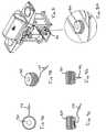
- FIG. 4Ais a cross-sectional view of a solenoid valve in a closed position
- FIG. 4Bis a cross-sectional view of the solenoid valve of FIG. 4A in an open position
- FIGS. 5A to 5Pillustrate various features of an embodiment of a liquid crystal display of the temperature control apparatus
- FIG. 6is an isolated isometric view of the barbecue of FIG. 1 showing a console, burners, and temperature control apparatus;
- FIG. 7is a partial rear view of FIG. 6 ;
- FIG. 8is an isometric view of the barbecue of FIG. 1 showing a tank support
- FIG. 8Ais an enlarged view of a tank sensor of FIG. 8 ;
- FIGS. 9A to 9Dinclude various views of a tank sensor of FIG. 8 ;
- FIG. 10illustrates an isometric view of the barbecue of FIG. 1 illustrating a tank support in an extended position
- FIG. 10Ais an enlarged view of the tank support of FIG. 10 ;
- FIG. 11Ais an isolated isometric view of the tank support of FIG. 10 ;
- FIGS. 11B to 11Dpresent different isolated views of the tank support of FIG. 10 and a shelf of the barbecue of FIG. 10 ;
- FIG. 12is an enlarged cross-sectional view of the tank support of FIG. 10 having a tank placed therewithin;
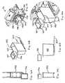
- FIG. 13is an isometric view of the barbecue of FIG. 1 with a lid thereof removed to reveal a divider;
- FIG. 13Ais an enlarged view of the divider of FIG. 13 ;
- FIGS. 13B to 13Dare various views of the barbecue of FIG. 13 and the divider therein;
- FIG. 14is an isolated isometric view of the divider of FIG. 13 ;
- FIG. 15is an isometric view of the barbecue of FIG. 1 and a storage receptacle
- FIG. 15Ais an enlarged view of the receptacle of FIG. 15 ;
- FIGS. 16A to 16Dpresent various isolated views of the storage receptacle, insert and slide rails of FIG. 15 ;
- FIG. 17is an isometric view of the barbecue of FIG. 1 and a grease receptacle
- FIG. 17Ais an enlarged view of the receptacle of FIG. 17 ;
- FIGS. 18A to 18Dare isolated views of a shelf and receptacle of the barbecue of FIG. 17 ;
- FIG. 19is an isolated isometric view of the barbecue of FIG. 2 showing an infrared burner
- FIG. 19Ais an enlarged view of the infrared burner of FIG. 19 ;
- FIGS. 20A to 20Dare isolated views of the infrared burner of FIG. 19 ;
- FIG. 21is a schematic flow diagram of aspects of the function of the temperature control device.
- the disclosed temperature control apparatusmay facilitate control of an internal temperature of a gas fuelled appliance, such as an outdoor gas barbeque.
- a gas fuelled appliancesuch as an outdoor gas barbeque.
- the description hereinis made in the context of a gas fuelled barbeque, but the disclosed temperature control apparatus may be applied to any manner of appliance, including gas fuelled appliances.
- the temperature control apparatuspermits a user to input a desired temperature set-point.
- the temperature control apparatusthen automatically controls the flow rate of gas into the barbeque to achieve the desired temperature.
- Thismay permit greater precision in the cooking of food with a gas fuelled appliance.
- more accurate and automatic temperature controlmay permit a barbeque to be used to bake, in addition to a more traditional grilling of meat. Even the grilling of meat may be improved given that an operator or user has the assistance of a somewhat automated control of the temperature within the barbeque.
- Such greater diversity of food that may be cooked with a barbequemay have certain advantages, such as encouraging a greater number of women to use a barbeque for cooking.
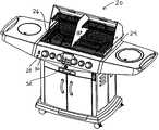
- FIG. 1illustrates a barbeque 20 , which may be a typical barbeque.
- Barbeque 20may include an openable lid 22 mounted to a base 24 .
- FIG. 2illustrates the barbeque 20 having lid 22 removed for illustration purposes.
- Base 24supports a grill 26 .
- Grill 26may be used to support food for cooking, or vessels (not shown) containing food for cooking.
- the particular configuration of the grill base and lidmay be modified significantly without materially affecting the operation of the temperature control apparatus.
- the grill 26may even be eliminated if suitable means, such as a container (not shown), are employed to support food to be cooked.
- Barbeque 20may also include a console 28 which may be mounted about base 24 .
- Console 28may be used to support one or more control knobs 30 , for manual control of associated valves, and part of a temperature control apparatus 32 .
- temperature control apparatus 32may simply be placed upon any suitable part of barbeque 20 and connected to barbeque 20 as described herein.
- temperature control apparatus 32may be used to modify existing barbeques to provide temperature control as described herein.
- the temperature control apparatusmay be integrated with a purpose built barbeque such as barbeque 20 .
- FIG. 3provides a schematic overview of the temperature control apparatus 32 . Many of the components described herein may be substituted by suitable components that are functionally similar. Temperature control apparatus 32 may include an input device 34 . Input device 34 may be a touch sensitive LCD screen (as illustrated), but may alternatively include some other suitable input device, such as a keypad or dial(s).
- Temperature control apparatus 32also includes a microprocessor 36 .
- Microprocessor 36may be electrically connected to input device 34 for receiving input from a user.
- Microprocessor 36is also operatively connected to at least one valve 38 .
- Valve 38may be any type of electrically or mechanically controlled valve suitable for changing the flow of a gas.
- valve 38is an electrically controlled valve.
- valve 38may be a latching or latch valve.
- a latch valve having at least two settings, being open and closed or high and low-flow,may be used either in place of or in addition to, another latch valve or a different type of valve such as a solenoid valve. It is preferable that a latch valve having a high and low-flow setting be used, as will be explained below.
- the latch valveadvantageously requires power to change from one setting (e.g., high) to another (e.g., low), but does not require power to maintain any particular setting. This may advantageously reduce the amount of power required for the temperature control apparatus 32 . This characteristic may be particularly useful if the temperature control apparatus is powered by battery (not shown) or other portable or limited power supply. If power supply is lost or runs out, then a capacitor (not shown) may be included in temperature control apparatus 32 to enable the latch valve to be switched one (or more) times in or to put it in a desired flow state. For example, if power is lost when the latch valve is in a low flow state, the capacitor may be used to switch it to a high flow state so that barbeque 20 may be then used as a conventional barbeque.
- FIGS. 4A and 4BAlternative valves such as solenoid valve 40 , as shown in FIGS. 4A and 4B , may be used. Any suitable solenoid valve may also be used, and not just the valve illustrated in FIGS. 4A and 4B .
- FIG. 4Ashows solenoid valve in a closed position.
- FIG. 4Bshows the solenoid valve in an open position.
- Valve 40may have an opening 41 to encourage a low flow rate when the valve is “closed”.
- solenoid valve 40is switchable between at least a low-flow rate and a high-flow rate.
- a solenoid valvemay be less suitable for uses where power is at a premium because a solenoid valve typically requires power to maintain the valve in at least one of its flow states.
- Valves such as 38 and 40may alternatively include two valve mechanisms within a single unit, which may provide a more cost effective and/or compact arrangement when more than one valve is employed.
- microprocessor 36may be operatively connected to a thermocouple, such as thermocouple 42 .
- Additional thermocouplesmay be used, as needed. For example, if temperature control apparatus 32 is used to control the temperature of more than one barbeque, or more than one area or zone within a given barbeque, then multiple thermocouples may be used. Additionally, multiple thermocouples may be used to obtain a more accurate reading within a single barbeque enclosure. In one embodiment just one valve may be used to control temperature in a single barbeque enclosure or zone.
- thermocouple 44is employed so that temperature control apparatus 32 may be used to control the temperature within two different zones of barbeque 20 (this is described in further detail below).
- an additional thermocouplesuch as meat probe 46 may be connected to microprocessor 36 to permit the monitoring of the temperature of a food, such as meat being cooked within barbeque 20 .
- Temperature control apparatus 32may receive power from a power supply 48 .
- Power supply 48preferably provides 12 volts AC.
- Temperature control apparatus 32may also be configured to run on some other suitable voltage, including DC current, provided that suitable circuitry is included with temperature control apparatus 32 to accept such power. Using DC power may permit a battery or other portable form of power to be used. Typically, a 120 volt AC power supply is used and is then converted by a transformer to 12 volt AC power.
- Microprocessor 36may accept other inputs such as from a tank level sensor 50 .
- Tank level sensor 50provides a signal to microprocessor 36 to indicate the level of a connected fuel supply, which may be used to calculate the time remaining before additional fuel is needed either at the current fuel usage rate, an average fuel usage rate, or some other appropriate measure. This may done by monitoring the rate of change over time and predicting (extrapolating) the time when the tank will be out of fuel. If another gas source is used, for example from a natural gas line, then the tank sensor functionality may be removed or eliminated.
- the various connections between the components of the temperature control apparatus 32may be wired or wireless, and may include standard connectors, such as 2.5 millimetre audio style connectors, or may be hard-wired or use some other connection, as desired.
- Input device 34may have any of a number of suitable configurations as noted. At its simplest, input device 34 may be a dial, switch or lever that may be moved to select a higher or lower desired temperature for the barbeque 20 .
- input device 34includes an LCD screen 52 that may be backlit (or may have a sensor or timer to limit or eliminate the amount of back light in order to conserve power, if needed).
- LCD screen 52may be touch sensitive, or may be activated using some other input device such as a keypad, a keyboard, a light pen, a mouse, or some other device.
- the particular layout and style of the graphics for the interface of LCD screen 52may be configured as needed. No particular layout is required. Aside from the functionality to input a set-point temperature, all other functionality is optional. However, some configurations, such as those described herein, may facilitate inputs to be made and readings to be displayed.
- the temperature control apparatus 32may be activated by pressing the on/off button 53 of the LCD screen 52 (when temperature control apparatus 32 is not activated, barbeque 20 may operate as a conventional barbeque). Once activated, a desired temperature may be set by pressing the temperature area 54 of the LCD screen 52 . A set-point temperature may then be entered using up and down arrows 56 and 58 to increase or decrease the desired target temperature.
- the barbeque 20may be configured to achieve a wide range of temperatures. For example, the barbeque 20 may be configured to achieve temperatures between 40° C. and 200° C., or 35° C. to 300° C., or 50° C. to 350° C., or to any suitable combination of temperature ranges. The barbeque 20 may also be purpose built for a very narrow temperature range such as between 200 and 300° C.
- the temperature control apparatus 32may be configured to achieve any range of temperatures depending on the barbeque 20 configuration.
- microprocessor 36compares a signal received from thermocouple 32 .
- the signalindicates the temperature in the vicinity of thermocouple 42 . If the temperature conveyed by thermocouple 42 is within a given range of the set-point temperature, then nothing is done by microprocessor 36 .
- the range within which the temperature conveyed by thermocouple 42 may differ from the desired set-pointmay be as low as a fraction (for example, 0.1 of a degree) or as large as one or more degrees, including plus or minus 5° or 10° (Celsius or Fahrenheit). Improved accuracy may be obtained by reducing the range by which the temperature conveyed by thermocouple 42 may differ from the desired temperature set via input device 34 .
- the range of variation relative to the desired temperaturemay have a first or lower threshold value, and a second or upper threshold value. While the difference between the lower and upper threshold values may be small, in order to more closely achieve the desired temperature, a small difference in these values may cause the valves, and possibly other components to operate more frequently. This frequent operation may reduce the effective lifetime of such components. Such frequent use may also increase the power consumption, which may be undesirable if there is a limited or restricted power supply. While a greater difference between upper and lower threshold values may produce greater variation in the actual temperature of the barbeque 20 , less energy may be used and a longer life may be obtained from at least some of the components of barbeque 20 .
- a lower/upper difference of 10° F.may provide suitable results.
- rangesas small as 1° F. or as large as 50° F., or larger depending on the cooking needs.
- the upper and lower limits for the rangemay be static relative to the temperature set-point. For example, they may be set to always be within 5° F. of the desired temperature.
- the upper and lower set-pointsmay vary depending of the temperature set-point.
- the upper and lower limitsmay be within 10° F. of the desired temperature at a lower temperature such as 40° F., whereas they may define a smaller range, for example, plus or minus 3° F., relative to a higher set-point temperature, such as 200° F.
- This dynamic variation of upper and lower set-pointsmay be used advantageously to take advantage of the thermal dynamic characteristics of the barbeque assembly 20 .
- microprocessor 36When microprocessor 36 receives a signal from thermocouple 42 indicating a temperature greater than (or optionally, equal to) an upper limit value, microprocessor 36 sends a signal to valve 38 to cause it to enter a low or no-flow state.
- valve 38enters a low-flow state.
- Microprocessor 36compares temperature information from thermocouple 42 and compares it with the upper and lower limits as frequently as once per second, or fraction of a second, or as infrequently as every several minutes. The typical range for this comparison may be between 0 to 30 seconds. This provides sufficient time for a change in the temperature of the barbeque 20 to stabilize after a change in the state of valve 38 .
- microprocessor 36may signal valve 38 to turn on or to switch to a high-flow state. This may cause the temperature within barbeque 20 to increase above the lower threshold.
- Microprocessor 36may continue to receive signals from thermocouple 42 , and to cycle valve 38 between high and low (or, in some embodiments, off) states in order to achieve a desired temperature within barbeque 20 .
- thermocouple 42compares the temperature of thermocouple 42 against the lower and upper temperature thresholds every 5 seconds, and the upper and lower threshold values are separated by a range of 10° F.
- the temperature within barbeque 20having a closed lid 22 , has been found to be maintainable within as little as one or two degrees Fahrenheit of the desired temperature.
- a safety featuremay be included in the temperature control apparatus 32 .
- Microprocessor 36may include memory (not shown), if needed, for example, for storing historical temperature data. In an embodiment, at least the previous reading from thermocouple 42 may be stored for comparison with a subsequent reading. If a difference between the previous and subsequent readings relative to the time between readings is sufficiently great or sufficiently small, then an alarm may sound. Furthermore, if the differences in the previous and subsequent temperatures is great enough, microprocessor 36 may signal valve 38 to change into an off or low-flow state. This may occur, for example, if there is a flare-up or fire within the barbeque 20 , causing a rapid increase in the temperature therein. Alternatively, if there is a rapid decrease in temperature, then the flame may have gone out and the flow of fuel may need to be shut off or reduced. In either case, an alarm may sound to alert the user to an error condition.
- thermocouplemay be employed within a single barbeque assembly 20 .
- microprocessor 36may take an average or weighted reading of the various thermocouples to determine the temperature of the barbeque 20 .
- barbeque 20may be divided into two or more zones (or additional barbeques may be connected to temperature control apparatus 32 ), with at least one thermocouple being placed in each zone or barbeque.
- thermocouple 44When temperature control apparatus 32 is connected to thermocouples in two or more thermally separated zones of barbeque 22 , different temperature states may be achieved within barbeque 20 .
- a desired temperaturemay be set for thermocouple 44 in a manner similar to that set for thermocouple 42 .
- Thermocouple 44may be set at a temperature the same as, higher than, or lower than the zone in which thermocouple 42 is placed (for example, zones 1 and 2 are illustrated in FIG. 3 ). Zones 1 and 2 may be thermally separated by a physical divider (as described in further detail below) or they may simply represent different areas within barbeque 20 . If zones 1 and 2 are not physically divided, then achieving significantly different temperatures between thermocouple 42 and thermocouple 44 may be more difficult.
- barbeque 20may include a generally warmer area and a generally less warm area.
- at least one additional (or integrated) valve assembly 60may be used for each zone controlled by temperature control apparatus 32 .
- Microprocessor 36may then be configured to independently control each respective valve, such as 38 and 60 , in response to temperatures encoded by thermocouples 32 and 44 .
- Temperature control apparatus 32may also operate in conjunction with a thermocouple 46 .
- Input device 34may be used to enter a type of meat (such as, pork, beef, chicken, or lamb) and a desired doneness (e.g., well done, medium, medium-rare, or rare).
- Microprocessor 36may then control the temperature of barbeque 20 employing one or both thermocouples 42 , 44 , to achieve a pre-determined temperature in order to cook the meat to a desirable extent.
- Temperature control apparatus 32may additionally be connected to a tank level sensor 50 for determining the amount of fuel left in a connected fuel reservoir, such as a liquid propane tank 66 .
- An icon, such as icon 67may graphically or numerically illustrate the amount of fuel remaining.
- Microprocessor 36may be connected to a tank level sensor (described below), and may be configured to shut off valves such as valve 38 when the tank is low or empty.
- Tank 66may be provided with a regulator 68 for ensuring that the pressure of the fuel provided to barbeque 20 is at a constant pressure, regardless of the flow setting of the valves (such as valve 38 ). Hence, even though valve 38 may be in a low-flow state, the pressure of the fuel transmitted therethrough to barbeque 20 may be at generally the same pressure as the fuel transmitted when valve 38 is in a high-flow state.
- the valves, such as valve 38 and valve 60do not include a regulator or have a regulator associated therewith. This may be advantageous because it may reduce the chance that a “flame-out” occurs within barbeque 20 due to insufficient fuel pressure. It may also reduce the cost of valves 38 and 60 .
- a fuel pressure of about 11 inches water column (WC)may be employed for propane and about 7 inches WC for natural gas. This may vary depending on requirements and government or other regulations which may vary by jurisdiction.
- FIGS. 5A to 5Tillustrate an example of a configuration for a LCD screen 52 of the temperature control apparatus 32 .
- the particular layout, font, FIGUREs, and functionality includedmay be varied, added to, or removed.
- functionality relating to a meat probe or tank level sensormay be eliminated or removed to reduce cost or for some other reason.
- means for inputting a desired temperature set-pointmay be included, unless the system is designed to always maintain the same temperature, such as for a commercial application.
- Features highlighted for LCD display 52are shown darkened in the figures for ease of illustration. The various features may be darkened or not in an embodiment. Different colours and lighting, including back-lighting, may be employed to improve readability and usability.
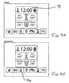
- FIG. 5Ashows an on/off button graphic 53 . Pressing screen 52 about this graphic, causes the temperature control apparatus 32 to switch off and on, as desired.
- barbeque 20may operate as a conventional barbeque.
- barbeque 20may be configured without one or more, or all of knobs 30 .
- temperature control apparatus 32may control all fuel flow to barbeque 20 .
- Valves 38may be configured to include an “off” setting, or fuel flow may be switched off, for example manually, at tank 66 , or at some other fuel source that is connected to barbeque 20 .
- barbeque 20may be difficult to achieve a desired temperature without turning temperature control apparatus 32 on.
- FIG. 5Billustrates a countdown timer that may be included.
- the countdown timermay be set in a manner similar to that described for the temperature setting.
- the countdown timermay be used to turn off or change fuel flow after a certain period of time. Alternatively, it may be used as a simple timer. This feature may be activated by pressing the hour glass icon 70 and adjusting the desired time by pressing the arrow keys 56 and 58 .
- FIG. 5Cillustrates icons of display 52 that may be used to set a temperature, as described above. If temperature control apparatus 32 is configured to control two zones (it may be used for just one zone or barbeque), then zone control button 54 may be pressed, followed by increase/decrease arrows 56 and 58 in order to enter a desired temperature set-point. A similar operation may be followed for a second zone by pressing second zone button 72 . If both zones are to have the same temperature set-point, then button 74 may be pressed and both zones desired temperatures will be set at the same time by pressing increase/decrease arrows 56 and 58 .
- FIG. 5Dincludes a food-type entry input 76 . This may be used to toggle or scroll through different meat types, and to enter a desired doneness for the food as illustrated at 62 .
- Microprocessor 36may be encoded with any variety of food types and characteristics to be entered via display 52 .
- FIG. 5Eillustrates setting of a clock feature 78 .
- Microprocessor 36may be configured to maintain display of clock 78 even when display 52 has been switched off.
- Clock 78may be set by pressing in the area of clock 78 and the up or down arrow at the same time in order to increment or decrement the clock setting. It should be noted that all functions are preferably configured to require simple single button sequential pressing to avoid the need for a separate clock icon. Both the clock and arrow areas of display 52 are pressed at the same time for setting. However, an alternative configuration could be employed so that a clock icon is pressed and the arrow keys subsequently pressed in order to set the clock.
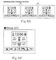
- FIG. 5Fillustrates employing the increase icon 56
- FIG. 5Gillustrates using the decrease icon 58 . These icons are used to increase and decrease values associated with the various functions of the temperature control apparatus 32 .
- FIG. 5Hillustrates a preheat function that may be encoded into microprocessor 36 .
- a preheat button 80 of display 56may be pressed. This causes microprocessor 36 to activate valve 38 to a high setting so that zone 1 (and any other zone activated, in which case additional valves are activated). Valve 38 is activated to a high flow rate so that the associated zone in barbeque 20 quickly achieves a predetermined preheat temperature.
- a preheat temperature of 400° F.is pre-programmed in microprocessor 36 as the preheat temperature. Any other temperature may be pre-programmed as a preheat temperature.
- temperature control apparatus 32may be configured, including screen 52 , to have a manually settable preheat temperature. Once the preheat temperature is reached, the temperature control apparatus may beep one or more times, at intervals if desired. For example, the temperature control apparatus 32 may beep for a period of 5 seconds every minute for 5 minutes.
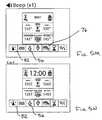
- FIG. 5Millustrates a food-specific function that may be coded into microprocessor 36 and implemented into display 52 .
- a food icon 76may be used in conjunction with a probe such as a thermocouple meat probe 46 (see FIG. 3 ).
- the temperature control apparatus 32may issue a beep.
- the probereaches a temperature over the set-point (for example, 5° over the set-point, a continuous or repeated beep may issue).
- a sample table of goal temperatures for various food itemsfollows. These values may be pre-programmed into microprocessor 36 . Any other of a wide range of values may be pre-coded for use with different types of foods or cooking scenarios.
- temperature control apparatus 32may be configured to enable coding of values by a user. In such case, a random access memory, such as a stable flash memory may be employed in the temperature control apparatus.
- FIG. 5Killustrates entering a food type by repeatedly pressing the food icon 76 .
- FIG. 5K at the right side thereofillustrates the various food types that will be displayed as food-type icon 76 is pressed.
- FIG. 5Lillustrates display 52 after it has been set to cook beef medium-rare.
- FIG. 5Lillustrates that the probe temperature is below the set temperature of 145° F.
- FIG. 5Ifurther illustrates temperature control setting.
- temperaturemay be set in five degree increments.
- the temperature control apparatus 32may be configured to enable other increments including fractions of a degree.
- the temperature control apparatus 32may be configured to sound an alarm or to flash a light once a target temperature has been reached.
- FIG. 5Jillustrates a condition when the target temperature cannot be reached after a certain period of time.
- the period of timemay be predetermined by encoding microprocessor 36 accordingly. For example, if a set-point temperature is not achieved within 10 minutes, then an alarm, whether visual, auditory or other sensory indicator, may be activated to indicate to a user that the target temperature cannot be achieved, either because the temperature is too high or too low. The goal temperature may then be reset accordingly or the barbeque 20 may be examined to determine whether there is a fault.
- FIG. 5Nillustrates that up button 56 may be used in conjunction with automatic temperature control button 82 to toggle between different temperature units, such as Celsius and Fahrenheit.
- FIG. 5Oillustrates the fuel tank level icon 67 described above.
- Icon 67may be configured to illustrate a progressively empty fuel vessel as illustrated in FIG. 5P .
- Processor 36may be programmed to query the tank level sensor 50 at a predetermined interval such as 30 seconds.
- Tank level icon 67may then include one or more bars corresponding to a predetermined level.
- a given number of barsmay be activated in icon 67 to illustrate graphically the amount of fuel remaining.
- a number corresponding to the level of the fuel tankmay be illustrated.
- An alarmmay be activated when the fuel tank 66 reaches a predetermined level, such as 10%.
- FIG. 6is an isolated view of barbecue base 24 and console 28 .
- FIG. 6illustrates that the barbecue 20 may include an auxiliary burner (not shown) connected by conduit 84 .
- the present embodimentmay include three burners 86 , 88 and 90 .
- Barbecue 20may be configured to have any number of burners, including just one burner, or multiple burners. If just one burner, such as burner 86 , or 88 , is employed, then temperature control apparatus 32 will typically include just one valve assembly, such as valve assembly 38 .
- Each burner 86 , 88 and 90may define separate heating zones within barbecue 20 . In such case, barbecue 20 may be thermally separated into three different zones. In the embodiment shown in FIG. 6 , barbecue 20 includes just two heating zones.
- Burners 86 and 88may be associated with heating zone 1 and burner 90 may be associated with heating zone 2 .
- Heating zones 1 and 2may be separated by a divider (discussed below) that is resistant to thermal transmission. This may ensure that zones 1 and 2 may be controlled independently to have different temperatures, or they may be controlled relatively independently to have the same temperature.
- Burners 86 , 88 and 90may have different configurations, or the same configuration, and they may include the burner types illustrated, or any other burner known in the art, including those conventionally used for gas fuelled appliances, such as barbecues.
- FIG. 7illustrates an isolated rear view of console 28 and associated components of barbecue 20 , including components of the temperature control apparatus 32 .
- FIG. 7should be viewed in conjunction with FIG. 6 .
- control knobs 30 , 92 and 94each associated with a respective burner 86 , 88 and 90 , may be used to control in a conventional manner the flow of a combustible fuel in a conventional manner.
- Each control knobincludes an associated valve. Any suitable control knob and valve combination may be used, including those well known in the art. Additional control knobs may be included, such as control knobs 96 (e.g., for a rotisserie), 98 and 100 .
- Control knob 98may be used to control the flow of fuel to an additional burner or other appliance via conduit 102 which connects to conduit 84 (shown in FIG. 6 ).
- Each valve, such as valve 38 , associated with a zonemay have a minimum flow rate that is similar to or equal to the sum of the flow rates of the associated controls, such as controls 30 and 92 .
- valve 38preferably has a minimum flow rate of 10,000 BTUs (i.e., 5,000+5,000). This configuration permits valve 38 to supply a minimum amount of fuel to controls 30 and 92 . If the minimum flow rate of valve 38 is made lower than the sum of the minimum flow rates of the associated control or controls, then it is possible for any associated burner, such as burner 86 or 88 to “flame out” due to an insufficient fuel supply.
- the minimum flow rate for valve 38may be in the range of 10,000 BTUs, and the maximum flow rate may be in the range of 25,000 BTUs. Higher and lower values may also be suitable depending on the configuration such as the volume of the barbeque to be heated.
- Control 30may be configured to include an off position in which the flow of fuel to burner 86 is inhibited.
- the off positionmay be a discreet position.
- Control 30may click or snap into an off position.
- Control 30may also have discreet or continuous high and low positions, permitting high and low rates of fuel flow to burner 86 .
- control 30must be pushed when it is in an off position before it may be turned to a high or low position. Once in a high, low, or intermediate position, it may be released. Control 30 may then be rotated between high and low positions, without pushing it, in order to set a fuel flow rate that is high, low or at some intermediate position. To return to an off position, control 30 may be pressed and turned to the off position.
- the other valves 92 , 94 , 96 , 98 and 100may be similarly configured.
- the controlssuch as controls 30 , 92 and 94 , that are associated with the temperature control apparatus 32 , may also be used at the time that the temperature control apparatus 32 is activated. For example, when control 30 is put to an intermediate flow position, temperature control apparatus 32 may operate valve 38 to cycle gas flow between the low flow rate of valve 38 and the intermediate flow rate as set by control 30 . If control 30 is placed to a high flow rate setting, then the temperature control apparatus 32 may operate to achieve and maintain temperatures within a broader range. When temperature control apparatus 32 is used, all associated valves ( 30 , 92 and 94 ) will typically be placed by a user to a high flow position to provide the temperature control apparatus 32 with the largest possible range of operation.
- Temperature control apparatus 32may also operate if all control knobs, such as control 30 are eliminated. In such case, flow of the fuel may be turned off as a shut-off valve 106 of regulator 68 . All control knobs may be conveniently connected via a manifold 108 . When the temperature of more than 1 zone is to be controlled, then the controls and associated burners for a given zone may be connected via separate manifolds. In the present example, a second manifold 110 may be included for zone 2 . This can be seen in FIG. 7 . Manifold 108 may connect burners 86 and 88 , and associated controls 30 and 92 . Manifold 108 may also be connected with valve 38 . In this way, the temperature control apparatus 32 may separately control the burners in zone 1 via valve 38 , and the burners in zone 2 via valve 60
- Temperature sensorssuch as thermocouples 42 and 44 may be located within each of zones 1 and 2 .
- the thermocouplesmay be mounted to a side of base 24 , or any other location.
- Thermocouples 42 and 44are preferably placed to avoid contact with any drippings or splatter from food cooked within barbecue 20 .
- Barbecue assembly 20may additionally include an igniter for igniting fuel communicated to the burners, such as burner 86 .
- an igniterfor igniting fuel communicated to the burners, such as burner 86 .
- a match or other suitable meansmay be used to ignite the burners.
- FIG. 8shows barbecue 20 without closure members 112 (as shown in FIG. 1 ).
- FIG. 8illustrates a possible placement of tank sensor 50 .
- Tank sensor 50is illustrated in greater detail in FIGS. 9A to 9D .
- Tank sensor 50may be used to determine the fuel level in a tank 66 associated therewith.
- Tank sensor 50may be connected to temperature control apparatus 32 via a connector 114 .
- a sensorsuch as that manufactured by Sensotech Inc. of 1250 Rene-Levesque Boulevard, Montrol, Quebec may be suitable, or as disclosed in Patent Corporation Treaty application no. PCT/CA2005/001935 and U.S. patent application Ser. Nos. 11/029, 415 and other applications claiming sensor devices and which are owned Sensotech Inc., the disclosures of which are incorporated herein by reference.
- FIGS. 10 and 10Aillustrate a support for a fuel reservoir such as fuel reservoir 66 (see also FIG. 12 ).
- support 116includes at least 1 protrusion 118 that corresponds to a lower portion 120 (see FIG. 12 ) of tank 66 .
- Support 116may additionally include portions defining a void 122 for receiving a stand 124 of tank 66 .
- Void 122may be configured as a continuous slot (not shown) for receiving an edge of stand 124 .
- Tank support 116may additionally include a rebate 126 for receiving sensor 50 .
- Rebate 126may be configured to conform to a perimeter of sensor 50 so that sensor 50 engages edges defining rebate 50 in a snap fit.
- rebate 126may be configured for a friction fit, or may simply retain sensor 50 by gravity fit.
- Tank support 116may be formed integrally with a shelf 128 of barbecue assembly 20 . This may make it difficult to install, remove, and replace tank 66 . Accordingly, tank support 116 may be configured as a separate member movable relative to shelf 128 . Tank support 116 may be mounted to two shelf 128 on rails, sliders or some other suitable arrangement. As illustrated in FIG. 10A , tank support 116 may be configured to slidably engage shelf 128 . A stabilizer, such as rail 130 , may be included to provide additional support and guidance to tank support 116 when it is moved relative to shelf 128 .
- Tank support 116may also include a guide in the form of a rib for engaging a complimentary feature of shelf 128 .
- Rib 132may be located upon either side of tank support 116 to permit generally linear movement of tank support 116 relative to shelf 128 .
- Rib 130 and rib 132serve to discourage displacement or tipping of tank support 116 relative to shelf 128 when shelf 128 is moved for removal or replacement of tank 66 .
- Tank support 116may additionally include a retainer or a lock such as latch 134 .
- Latch 134may be movable within tank support 116 so that it engages shelf 128 or a complimentary feature in shelf 128 . As shown in FIG. 12 , latch 134 extends generally perpendicular to a plane of movement of tank support 116 so that it may engage a corresponding feature (not shown) of shelf 128 . Latch 134 discourages movement of tank support 116 relative to shelf 128 when tank support 116 is in engagement with shelf 128 , and tank 66 is positioned for use. This arrangement may further discourage movement of tank 66 when barbecue 20 is operated.
- FIG. 12is a cross sectional view providing further illustration of both tank support 116 and the positioning of tank level sensor 50 .
- Tank level sensor 50preferably contacts tank 66 sufficiently that it may communicate and receive signals therewith in order to determine the amount of fuel within tank 66 .
- FIG. 13illustrates barbecue 20 configured to have multiple zones, described above.
- barbecue 20may be provided with thermally differentiated zones therein.
- a dividersuch as divider 136 may be included with barbecue 20 to encourage or facilitate thermal differentiation between the various zones.
- thermally differentiated zones 1 and 2are illustrated.
- thermally differentiated zonesmay exist, for example, if a high flow rate fuel is provided to one burner, such as 86 , and a low flow rate of fuel is provided, for example, to burner 90 , then zone 1 may be generally warmer than zone 2 . However, when lid 22 is closed, heat from the warmer zone will tend to transfer to the less warm zone, thus inhibiting differentiated cooking between zone 1 and zone 2 .
- a dividersuch as divider 136
- a dividerin order to thermally separate two or more zones within barbecue 20 may permit thermally differentiated cooking. For example, a steak or other meat requiring a higher cooking temperature may be included in zone 1 , whereas vegetables requiring a lower temperature may be included in zone 2 . This may permit the cooking of both meat and vegetables at the same time, on the same barbecue, but at different temperatures. If a sufficient air seal is achieved between zones 1 and 2 when lid 22 is closed and divider 136 is in place, then the effect of flavours and other aromas produced by the cooking of food in one zone may be reduced in the other zone, thus preserving flavours of items cooked. However, an air seal is not required for divider 136 to operate.
- Divider 136may be made of a material that resists the transfer of thermal energy, such as a ceramic. However, thermally conductive materials, including metals, may be used because such materials will also serve to inhibit thermal transfer between zones 1 and 2 . A combination of materials such as insulation sandwiched between sheets of metal, may also be employed.
- Divider 136may conform to an inside perimeter of lid 22 and base 24 when lid 22 is closed. In such configuration, divider 36 may divide or bifurcate the volume enclosed by base 24 and closed lid 22 . Divider 136 may divide such volume into two equal volumes, or unequal volumes depending on cooking needs, such as the grill 26 area required, and the placement of burners, such as burners 86 , 88 and 90 .
- FIG. 13illustrates divider 136 in a plane generally perpendicular to grill 26 and generally perpendicular to a plane of the front of grill 20 .
- Divider 136may alternatively be placed in any other orientation that serves to thermally separate the internal volume of grill 20 .
- multiple dividers 136may be employed, for example, to thermally separate each of burners 86 , 88 and 90 .
- divider 136may limit the effect of different temperatures in zones 1 and 2 on each other.
- divider 136may limit the effect of a temperature in zone 1 on zone 2 by not more than plus or minus 10 degrees Fahrenheit.
- zone 1if the temperature of zone 1 is 300 degrees Fahrenheit, and a desired temperature of zone 2 is 200 degrees Fahrenheit, then zone 1 will generally, at most, raise the temperature of zone 2 to 210 degrees Fahrenheit with divider 136 in place. As noted below, the extent of this effect may depend on the material used for divider 136 and the extent to which divider 136 seals zone 1 from zone 2 .
- divider 136preferably conforms to an internal perimeter of combined lid 22 and base 24 , it needs not completely conform to such internal perimeter. With reduced conforming to such internal perimeter, divider 136 may be less thermally inhibiting. Nevertheless, even a limited amount of thermal resistance by divider 136 to the transfer of heat between zones 1 and 2 may provide a suitable differentiation in cooking temperature in each of zones 1 and 2 .
- Divider 136may be cut, stamped, moulded or otherwise formed as a single sheet, or as multiple sheets or pieces connected together. As noted, divider 136 may be made of a metal, a plastic, or some other substance that resists burning.
- divider 136may be a single, generally continuous, generally planar sheet. Grill 26 may be formed of two separated grill parts (not shown). Divider 136 may then be placed between each grill part. The grill parts may serve to support divider 136 .
- Divider 136may alternatively be provided with one or more rebates for avoiding features of grill 20 that may inhibit placement of divider 136 .
- divider 136may be provided with one or more grill rebates 138 .
- Rebates 138may be dimensioned and located to receive a portion of grill 26 that may inhibit placement of divider 136 as shown in FIG. 13A .
- Rebates 138may each receive one or more of the steel members that form grill 26 .
- the positioning, number, and orientation of rebates, such as rebates 136may be determined by the particular configuration of a given barbecue.
- a barbecuemay additionally include a warming rack 140 .
- divider 136may include a warming rack rebate 142 to accommodate warming rack 140 , as seen in FIG. 13A .
- Warming rack rebate 142may be configured to closely correspond to a portion of a perimeter of warming rack 140 .
- rebatessuch as rebate 142 may generally correspond to a feature such as warming rack 140 , and may permit a limited amount of thermal transfer, including air, to pass.
- the rebates, such as rebate 142may be made large enough for easy passage of obstructions, such as warming rack 140 , therein. If a given barbecue configuration does not include obstructions inhibiting the placement of divider 136 , then divider 136 need not be provided with any rebates.
- Rebates 138in turn define tongues 144 (additional tongues may be defined such as tongues 146 and 148 ).
- the tonguestogether serve to inhibit movement of energy, air, fumes and other matter between the zones.
- Divider 136may include a stabilizer, attachment, or other feature to maintain its intended placement, and to permit divider 136 to resist movement when barbecue 20 is used.
- a stabilizer 150may be included at one or both ends of divider 136 .
- Stabilizer 150may be configured to abut a corresponding feature of grill 26 .
- Stabilizer 150may alternatively be located at an intermediate portion of divider 136 .
- stabilizer 150may be placed adjacent to any part of rebate 142 to provide stabilization of divider 136 against warming rack 142 .
- 2 stabilizers 150are provided to lie upon grill 26 in a direction transverse to a plane of divider 136 . In this configuration, stabilizer 150 may inhibit lateral movement of divider 136 .
- Stabilizer 150is illustrated as being stick-like.
- stabilizer 150may be provided at an angle less than 90 degrees relative to divider 146 , in order to still impart stability to divider 136 .
- Other protrusions from divider 136may also be included so long as they provide a measure of support to divider 136 in order inhibit its movement when installed in barbecue 20 .
- divider 136may be made to have a thickness approximating the spacing of grill 26 . In this way, a friction fit may be formed between divider 136 and grill 26 when it is inserted therein.
- Divider 136may alternatively be permanently or temporarily attached to one or both of grill 26 and base 24 .
- divider 136may be welded, caulked, screwed, bolted, or otherwise mounted to grill 26 or base 24 , or both.
- Divider 136may alternatively be attached to an inside surface of lid 22 so that it is moved in and out of place by opening and closing lid 22 . In such configuration, the shapes of one or more of rebates 138 and 142 may need to be changed to accommodate this movement.
- Support for divider 136may alternatively, or additionally, be provided by a feature of base 24 (not shown).
- base 24may include a receptacle or groove for receiving an edge of divider 136 in order to maintain its position.
- Such groovepreferably has a width corresponding to, or marginally less than, a width of divider 136 to provide a friction fit when divider 136 is placed therein.
- Divider 136may alternatively constructed of two or more separate pieces. For example, a divider portion (not shown) may be installed below grill 26 . A second complimentary portion may then be installed above grill 26 . Such configuration could serve to reduce the need for any rebates, such as rebates 138 . This in turn could reduce the extent to which thermal energy, air, and other matter can pass between zone 1 and zone 2 .
- divider 136may be installed through a slot provided in base 24 (not shown). In this configuration, divider 136 may be installed in a generally opposite direction to the manner illustrated in FIG. 13 . A retainer or other feature may be provided to prevent divider 136 from falling out of the slot and base 24 . A similar feature could also be provided using a slot in lid 22 .
- FIG. 15illustrates barbecue 22 and an internal storage system.
- the internal storage systemmay include a container 152 slidably mounted to shelf 128 , for example via conventional telescoping rails 154 , and a nestable container 156 .
- Container 152may be made of any suitable material, such as a plastic, and may be dimensioned to occupy a suitable portion of a volume defined by barbecue shelf 128 , barbecue walls 158 , doors 112 (see FIG. 1 ) and back (not shown).
- Storage 152may have generally rectilinear dimensions, but may also be rounded or some other shape, as required.
- Container 152may be slideably mounted to shelf 128 by providing a complimentary indent (not shown) in shelf 128 for receiving the bottom of container 152 .
- container 152may be mounted to a movable shelf (not shown).
- Container 152may be used to store grill 26 , or parts of grill 26 , or other components of barbecue 20 or tools or appliances used in conjunction with barbecue.
- Container 152may include a grip or handle 159 attached or integrally formed in some convenient location of container 152 , such as a top edge thereof.
- the storage systemmay also be provided with an insert, such as insert container 156 .
- Insert container 156preferably includes a lip 160 for supporting insert 156 upon edges 162 of container 152 .
- Container 156may additionally include a grip or handle such as an opening 164 . Any other suitable handle may alternatively or additionally be applied.
- FIG. 16A to FIG. 16Dillustrate various views of the storage system.
- FIGS. 17 , 17 A and FIGS. 18A to 18Aillustrate a receptacle 166 for receiving grease, fat or other matter that may drip, fall or otherwise reside within base 24 .
- An opening (not shown) within base 24may permit the passage of such material into receptacle 166 .
- Receptacle 166may be any convenient size and shape to define a volume suitable for receiving an predetermined amount of material, such as fat or grease, that may be caught therein.
- receptacle 166may have the following approximate dimensions: about 1 inch deep by about 8 inches wide by about 5 inches long. In the preferred embodiment, receptacle 166 has dimensions of 1.1 inches deep by 7.785 inches wide by 5.315 inches long.
- Receptacle 166may be supported by a shelf 16 A. Shelf 16 A may define an opening 170 for receiving receptacle 166 . Opening 170 may be a similar size and shape as receptacle 166 . Receptacle 166 may additionally have one or more protrusions, which may be in the nature of a continuous lip 172 for inhibiting passage of receptacle 166 through opening 170 . Lip 172 may traverse all or a part of a perimeter of receptacle 166 .
- Shelf 168may be movable within a slot 174 of barbecue 20 .
- Other slidable means or other feature permitting movement of receptacle 166 between a position for receiving matter to a position in which receptacle 166 may be removed,may also be employed.
- Shelf 168may also be conveniently provided with a grip or catch such as in the nature of a handle 176 .
- FIGS. 19 , 19 A and 20 A to 20 Dillustrate an infrared burner 178 that may be included in addition to burners 86 , 88 and 90 .
- infrared burner 178may be employed alone or in conjunction with any other number of burners or even with additional infrared burners.
- Control knob 100may be used to adjust the flow of fuel to infrared burner 178 (or another type of burner such as burner 179 , shown in FIG. 6 ).
- Temperature control system 32may be used to additionally control infrared burner 178 .
- control valve 100is connected to valve 60 of temperature control system 32 (infrared burner 178 is not shown in FIG. 7 for ease of illustration).
- temperature control apparatus 32may be used to control fuel flow to infrared burner 178 to achieve a desired temperature in zone 2 of barbecue 20 .
- Infrared burner 178may be placed in any convenient location, including above burners 86 , 88 and 90 to enable infrared burner 178 to cook food, for example, placed on a rotisserie above grill 26 (not shown).
- Software of temperature control apparatus 32may be programmed to include the following functions described below. One or more of the evaluations made by the software may be done in a different order as set out below, or as shown in FIG. 21 , as appropriate.
- the operation of the following disclosed aspects of the softwaremay begin at step 200 , for example, by a user turning on temperature control apparatus 32 .
- the softwareevaluates whether a condition exists in which an alarm should be activated due to barbeque 20 being too hot, or if the temperature measured within barbeque 20 increases or decreases in temperature at higher than a predetermined rate.
- Step 202may also evaluate whether any other safety or alarm condition exists. If such a condition exists, then the software instructs temperature control apparatus 32 to lower the flow rate of a connected fuel flow control device, such as valve 38 .
- valve 38maybe set to a low flow rate following an alarm or error condition. This is done to reduce the amount of fuel provided in the event that something is wrong with the burning of fuel. If control valve 38 is configured to have an off state, then the software may cause valve 38 to turn off in step 204 .
- step 206the software evaluates whether barbeque 20 is set for manual operation.
- temperature control apparatus 32may include an input for a user to select between manual or automatic operation. Alternatively, if no desired temperature set point is entered, then temperature control apparatus 32 may default to manual operation. In such case, in step 210 valve 38 (or other flow control device) may be set to permit fuel flow, and is preferably set to permit a high flow rate. In this manner, a user may manually restrict fuel flow using one or more of control knobs, such as control knobs 30 .
- the softwareassesses whether the measured temperature of barbeque 20 is within a predetermined range of a desired set point. For example, the software may determine whether the measured temperature is with 2° F. (for example, either 2° above or below a desired temperature set point). If the measured temperature is within this range then the software does not change the present flow rate of fuel, whether such flow rate is at a high rate, a low rate, or otherwise.
- a predetermined range of a desired set pointFor example, the software may determine whether the measured temperature is with 2° F. (for example, either 2° above or below a desired temperature set point). If the measured temperature is within this range then the software does not change the present flow rate of fuel, whether such flow rate is at a high rate, a low rate, or otherwise.
- step 222the software assesses whether the measured temperature is higher than the temperature range described above. For example, it may evaluate whether the measured temperature is higher than the desired set point temperature plus a set amount, such as 2° F. If the measured temperature is above such total, the software may send an instruction to lower or otherwise restrict the flow rate of fuel (in some embodiments it may instruct fuel flow to be turned off). If the measured temperature is not higher than the predetermined range, fuel flow is maintained in step 226 .
- a further step of evaluating whether the measured temperature is below the predetermined temperature rangemay be carried out. If the measured temperature is below such range then the flow of fuel may be increased, for example, by setting valve 38 to a high flow rate.
- the ultimate result of any stepis a return to just after start step 200 .
- Thispermits the continuous evaluation of the various states of barbeque 20 .
- Evaluationmay be performed by the software at any interval, for example, evaluation may be done many times per second, or evaluation may be done intermittently, such as every few seconds, every minute, or after a series of minutes. Of course, evaluation may be done at varying intervals, depending on the stage of cooking. For example, at start up, evaluation of the temperature state of barbeque 20 may be done every minute, however, once a temperature set point is approached, then evaluation of various states of barbeque 20 may be done more frequently. For safety, evaluation is preferably done frequently.
- step 202may change the ordering of one or more steps.
- the assessment of the alarm condition in step 202may occur after any other step described. It is also possible to evaluate one step more often than other steps.
- the measured temperature comparison in step 220may be conducted two or more times for every one time that the manual operation evaluation is conducted in step 206 .
- the alarm status evaluation of step 202may be conducted after each and every other step in the flow chart.
- barbeque 20may have one or more zones that may require different temperature control. In such case, additional zones may be controlled using similar steps as described herein.
- a set point temperatureif a set point temperature is below a preset minimum value (for example, a predetermined temperature in the range of 110° C. or 225° F.), the barbeque 20 may enter a manual mode where the flow rate may be manually set by the user and the temperature control apparatus 32 will not operate to control the valve 38 . Otherwise, if a mode of the temperature control apparatus 32 is set by a user to “preheat”, a predetermined preheat set point may be used as the target temperature instead of a user inputted desired temperature. Preheat may be pre-determined or coded in temperature control apparatus 32 at 200° C. or 400° F., or some other value for getting barbeque 20 in a state ready for cooking.
- a preset minimum valuefor example, a predetermined temperature in the range of 110° C. or 225° F.
- a usermay also set the temperature control apparatus 32 to a keep warm setting. If keep warm is set and the keep warm set point temperature is below the user set point temperature, the keep warm set point will be used as the target temperature by the temperature control apparatus 32 .
- the keep warm set pointmay be any suitable temperature that slows or stops the rate of cooking of food placed within barbeque 20 .
- the temperaturemay be pre-programmed.
- the keep warm temperaturemay also be activated when a timer (such as illustrated in FIG. 5B ) reaches zero. In response to the timer completing, the set point is reduced to the keep warm set point temperature.
- the user inputted desired temperature set pointmay be used as the target temperature.
- the temperature control apparatus 32changes the fuel flow rate to low flow rate. If the measured temperature is below the target temperature minus a predetermined amount or hysteresis, then the fuel flow rate may be changed to the higher flow rate.
- the hysteresismay be a pre-programmed (for example during manufacture or coding) at 1° C. or 2° F., or some other higher or lower value suitable for cooking. As noted, higher numbers may lead to less accurate cooking, but may reduce the wear on any movable parts such as valve 38 .
- the software of temperature control device 32may be pre-programmed to include the following features:
- the software of temperature control device 32may be pre-programmed to include one or more of the following safety features (the alarms may be auditory or visual or both, and may include a explanation of the nature of the alarm to be displayed on LCD 52 ):
- Normal Alarmthis may be activated by temperature control device 32 when the measured temperature is not approaching the desired set point over time. In this situation, the software continues to control normally, but alerts the user with the display and an alarm, such as an audible beep, to the possibility of an undesirable condition such cover left open, or an out of fuel condition.
- Overtemp Alarmthis may be activated by temperature control device 32 when the temperature, for example as measured by a thermocouple, exceeds a fixed programmable parameter. When this event occurs, an overtemp alarm may be triggered and the fuel flow rate reduced.
- OverAcceleration Alarmthis may be activated by temperature control device 32 temperature, for example as measured by a thermocouple, increases or decreases (for example by ramping up or down) too quickly. In such case, an undesirable condition such as a grease fire may exist.
- the software of temperature control device 32may then reduce the fuel flow rate, and may activate an alarm.
- temperature control device 32may be programmed to include a probe cook mode.
- a usermay set the probe temperature set point based on the type of meat and the desired wellness. From the software, this is a series of pre-programmed set points used for each wellness state that may be selected (left to right in degrees Fahrenheit, the table illustrates the set point probe temperature for rare, medium rare, medium and well, respectively):
- the temperature control device 32may be programmed to collect data from a tank level sensor that may provide an indication of the level of fuel in the tank and the time remaining at the current cook rate. This is done by monitoring the rate of change over time and predicting (extrapolating) the time when the tank will be out of fuel.
Landscapes
- Engineering & Computer Science (AREA)
- Chemical & Material Sciences (AREA)
- Combustion & Propulsion (AREA)
- Mechanical Engineering (AREA)
- General Engineering & Computer Science (AREA)
- Physics & Mathematics (AREA)
- General Physics & Mathematics (AREA)
- Automation & Control Theory (AREA)
- Remote Sensing (AREA)
- Baking, Grill, Roasting (AREA)
- Feeding And Controlling Fuel (AREA)
Abstract
Description
- assessing whether the flow control apparatus is to be automatically controlled;
- when the flow control apparatus is to be automatically controlled:
- assessing the temperature within the cooking apparatus;
- maintaining the flow state of the flow control apparatus when the temperature within the cooking apparatus is within the range of about:
- (i) an upper threshold value, which upper threshold value is greater than the desired temperature, and
- (ii) a lower threshold value, which lower threshold value is less than the desired temperature;
- assessing whether the temperature within the cooking apparatus is generally higher than the upper threshold value; and
- setting the flow control apparatus to the first flow rate when the temperature within the cooking apparatus is generally higher than the upper threshold value.
- assessing whether the temperature of the cooking vessel is about or higher than a predetermined safety threshold temperature;
- assessing whether the rate of increase in temperature is about or greater than a predetermined safety temperature increase rate; and
- assessing whether the rate of decrease in temperature is about or less than a predetermined safety temperature decrease rate.
- assessing whether the second flow control apparatus is to be automatically controlled;
- when the second flow control apparatus is to be automatically controlled:
- assessing the temperature within the second volume;
- maintaining the flow state of the second flow control apparatus when the temperature within the second volume is within the range of about:
- (i) an second upper threshold value, which second upper threshold value is greater than the second desired temperature, and
- (ii) a second lower threshold value, which second lower threshold value is less than the second desired temperature;
- assessing whether the temperature within the second volume is generally higher than the second upper threshold value; and
- setting the second flow control apparatus to the first flow rate when the temperature within the cooking apparatus is generally higher than the upper threshold value.
- a microprocessor for controlling operation of the flow control apparatus;
- an interface connected to the microprocessor for manually inputting the desired temperature; and
- a memory coupled to the microprocessor;
the temperature control device including a temperature control module resident in memory for execution by the microprocessor, the module being configured to: - assess the temperature within the cooking apparatus;
- maintain the flow state of the flow control apparatus when the temperature within the cooking apparatus is within the range of about:
- (i) an upper threshold value, which upper threshold value is greater than the desired temperature, and
- (ii) a lower threshold value, which lower threshold value is less than the desired temperature;
- assess whether the temperature within the cooking apparatus is generally higher than the upper threshold value; and
set the flow control apparatus to the first flow rate when the temperature within the cooking apparatus is generally higher than the upper threshold value.
- code for assessing the temperature within the cooking apparatus;
- code for maintaining the flow state of the flow control apparatus when the temperature within the cooking apparatus is within the range of about:
- (i) an upper threshold value, which upper threshold value is greater than the desired temperature, and
- (ii) a lower threshold value, which lower threshold value is less than the desired temperature;
- code for assessing whether the temperature within the cooking apparatus is generally higher than the upper threshold value; and
- code for setting the flow control apparatus to the first flow rate when the temperature within the cooking apparatus is generally higher than the upper threshold value.
| Well-Done | Medium | Medium-Rare | |||
| Beef |
| 170° F. | 160° F. | 145° F. | 135° | |
| Lamb | ||||
| 170° F. | 160° F. | 145° F. | 135° | |
| Veal | ||||
| 170° F. | 160° F. | 145° F. | 135° F. | |
| Chicken | 180° F. | |||
| Turkey | 180° | |||
| Pork | ||||
| 170° | ||||
| Fish | ||||
| 160° | ||||
| Hamburger | ||||
| 160° F. | ||||
- Off/Manual Mode—This mode permits a user to control the fuel rate manually.
- Preheat Mode—The
temperature control apparatus 32 controls the system to a predefined preheat set point and may sound or otherwise indicate an alert when thebarbeque 20 is at a preheat temperature. - Grill Temp Mode—The
temperature control apparatus 32 controls thebarbeque 20 temperature to a user defined set point for each zone, when more than one zone is employed. - Timer Mode—This mode is similar to Grill Temp Mode, except that once the settable timer expires, the set points may be automatically reduced to the keep warm set points.
- Probe Cook Mode—This mode is similar to Grill Temp Mode, except that once the probe temperature has reached the set point, the fuel rates of both zones may be reduced to minimum.
- {135, 145, 160, 170},//BEEF
- {135, 145, 160, 170},//LAMB
- {135, 145, 160, 170},//VEAL
- {180, 180, 180, 180},//CHICKEN
- {180, 180, 180, 180},//TURKEY
- {170, 170, 170, 170},//PORK
- {160, 160, 160, 160},//FISH
- {160, 160, 160, 160}//HAMBURGER
Claims (19)
Priority Applications (3)
| Application Number | Priority Date | Filing Date | Title |
|---|---|---|---|
| US12/271,905US9289096B2 (en) | 2007-11-16 | 2008-11-16 | Temperature control device and method |
| CA2643957ACA2643957C (en) | 2007-11-16 | 2008-11-17 | Temperature control device and method |
| US12/861,803US9329606B2 (en) | 2007-11-16 | 2010-08-23 | Temperature control apparatus and method for a barbeque grill |
Applications Claiming Priority (3)
| Application Number | Priority Date | Filing Date | Title |
|---|---|---|---|
| CAPCT/CA2007/002085 | 2007-11-16 | ||
| PCT/CA2007/002085WO2009062281A1 (en) | 2007-11-16 | 2007-11-16 | Temperature control apparatus for a barbeque grill |
| WOPCT/CA2007/002085 | 2007-11-16 |
Related Child Applications (2)
| Application Number | Title | Priority Date | Filing Date |
|---|---|---|---|
| US12/271,905Continuation-In-PartUS9289096B2 (en) | 2007-11-16 | 2008-11-16 | Temperature control device and method |
| US12/861,803ContinuationUS9329606B2 (en) | 2007-11-16 | 2010-08-23 | Temperature control apparatus and method for a barbeque grill |
Publications (2)
| Publication Number | Publication Date |
|---|---|
| US20090126714A1 US20090126714A1 (en) | 2009-05-21 |
| US7793649B2true US7793649B2 (en) | 2010-09-14 |
Family
ID=40638272
Family Applications (4)
| Application Number | Title | Priority Date | Filing Date |
|---|---|---|---|
| US12/743,354Expired - Fee RelatedUS10180691B2 (en) | 2007-11-16 | 2007-11-16 | Temperature control apparatus for a barbeque grill |
| US12/000,163Active - ReinstatedUS7793649B2 (en) | 2007-11-16 | 2007-12-10 | Temperature control apparatus and method for a barbeque grill |
| US29/331,922Expired - LifetimeUSD605466S1 (en) | 2007-11-16 | 2009-02-05 | Barbeque temperature control |
| US12/861,803Expired - Fee RelatedUS9329606B2 (en) | 2007-11-16 | 2010-08-23 | Temperature control apparatus and method for a barbeque grill |
Family Applications Before (1)
| Application Number | Title | Priority Date | Filing Date |
|---|---|---|---|
| US12/743,354Expired - Fee RelatedUS10180691B2 (en) | 2007-11-16 | 2007-11-16 | Temperature control apparatus for a barbeque grill |
Family Applications After (2)
| Application Number | Title | Priority Date | Filing Date |
|---|---|---|---|
| US29/331,922Expired - LifetimeUSD605466S1 (en) | 2007-11-16 | 2009-02-05 | Barbeque temperature control |
| US12/861,803Expired - Fee RelatedUS9329606B2 (en) | 2007-11-16 | 2010-08-23 | Temperature control apparatus and method for a barbeque grill |
Country Status (5)
| Country | Link |
|---|---|
| US (4) | US10180691B2 (en) |
| EP (1) | EP2217859A4 (en) |
| AU (1) | AU2007361169A1 (en) |
| CA (2) | CA2884436C (en) |
| WO (1) | WO2009062281A1 (en) |
Cited By (30)
| Publication number | Priority date | Publication date | Assignee | Title |
|---|---|---|---|---|
| US20090104573A1 (en)* | 2007-10-23 | 2009-04-23 | Wen Chou Chen | Gas burner system |
| US20090165774A1 (en)* | 2008-01-02 | 2009-07-02 | Char-Broil, Llc | Temperature measurement means for cooking appliances |
| US20090165778A1 (en)* | 2007-12-11 | 2009-07-02 | Garland Commercial Industries Llc | Energy efficient char-broiler |
| US20090183729A1 (en)* | 2007-11-16 | 2009-07-23 | Wolfedale Engineering Limited | Temperature control device and method |
| US20100083947A1 (en)* | 2008-10-06 | 2010-04-08 | Morris Guillory | Barbecue grill having a split lid |
| US20100132692A1 (en)* | 2008-12-01 | 2010-06-03 | Timothy Scott Shaffer | Gas grill |
| US20110088682A1 (en)* | 2007-11-16 | 2011-04-21 | Wolfedale Engineering Limited | Temperature control apparatus and method for a barbeque grill |
| USD671364S1 (en) | 2011-01-31 | 2012-11-27 | Techtronic Power Tools Technology Limited | Portion of a grill |
| USD671363S1 (en) | 2011-01-31 | 2012-11-27 | Techtronic Power Tools Technology Limited | Portion of a grill |
| US8539978B2 (en)* | 2011-05-03 | 2013-09-24 | Emerson Electric Co. | Gas valve unit with bypass flow |
| US20140037804A1 (en)* | 2012-08-03 | 2014-02-06 | Grand Mate Co., Ltd. | Temperature-controllable gas grill and the method of controlling temperature |
| US20140102316A1 (en)* | 2010-02-25 | 2014-04-17 | Bonnie Lee Buzick | Grill With Safety System |
| WO2014093512A1 (en)* | 2012-12-11 | 2014-06-19 | Garland Commercial Industries, Llc | Cooking grill with multiple gas heating zones front to back for improved grill plate temperature management |
| US20150292749A1 (en)* | 2014-04-14 | 2015-10-15 | Samsung Electronics Co., Ltd. | Oven and method for controlling the same |
| US20160353929A1 (en)* | 2015-06-08 | 2016-12-08 | Masterbuilt Manufacturing, Inc. | Gas-fired smoker with digital temperature control |
| US20170000283A1 (en)* | 2015-06-30 | 2017-01-05 | Samsung Electronics Co., Ltd. | Cooking apparatus having automatic keep warm function and method for controlling the same |
| US20170130966A1 (en)* | 2015-11-10 | 2017-05-11 | Wilfrido Barajas | Barbecue Grill Heating and Smoking Plates and Method |
| US20170164783A1 (en)* | 2015-09-10 | 2017-06-15 | SmokeSteak LLC | Multiple fuel cooking unit |
| US20190125129A1 (en)* | 2016-04-13 | 2019-05-02 | Outdoorchef Ag | Grill |
| US10292531B1 (en) | 2018-06-06 | 2019-05-21 | Innovative Product Solutions, LLC | Cooking device having heat sources in a stacked arrangement |
| US10495317B1 (en)* | 2018-11-19 | 2019-12-03 | Lifetime Products, Inc. | Dual-fuel source cooking devices |
| US10806301B2 (en) | 2018-06-06 | 2020-10-20 | Lifetime Products, Inc. | Cooking device having a lower door |
| US20210080112A1 (en)* | 2019-09-16 | 2021-03-18 | Enerco Group, Inc. | Systems and arrangements for portable heater with connectable accessory |
| US11346552B2 (en)* | 2018-03-06 | 2022-05-31 | Boneless Grills Sl | Universal device for the automation of gas powered ovens, barbecues and devices |
| US20230371746A1 (en)* | 2022-05-17 | 2023-11-23 | Revoace Inc. Limited | Barbecue grill operable to control the taste of food by temperature |
| US20240000266A1 (en)* | 2022-07-01 | 2024-01-04 | Nexgrill Industries, Inc. | Electronic Gas Grill Temperature Control Apparatus and Method |
| US12140314B2 (en) | 2019-01-25 | 2024-11-12 | Weber-Stephen Products Llc | Pellet grills |
| US12161264B2 (en) | 2021-03-08 | 2024-12-10 | Lifetime Products, Inc. | Drip tray for a cooking device |
| USD1054770S1 (en)* | 2023-08-17 | 2024-12-24 | Xiaomei Chen | Barbecue grill |
| US12408793B2 (en) | 2021-09-10 | 2025-09-09 | Weber-Stephen Products Llc | Methods and apparatus for automating shutdown processes of gas grills |
Families Citing this family (36)
| Publication number | Priority date | Publication date | Assignee | Title |
|---|---|---|---|---|
| USD602944S1 (en)* | 2007-11-16 | 2009-10-27 | Wolfdale Engineering Limited | Display screen with electronic icons |
| USD634578S1 (en)* | 2008-11-17 | 2011-03-22 | Wolfedale Engineering Limited | Combined shelf and console for a barbecue grill |
| US20110067685A1 (en)* | 2009-09-23 | 2011-03-24 | Myers Robert L | Gas-Fueled Food Cooker with a Sealed Heating Conduit |
| US20120276260A1 (en)* | 2009-11-17 | 2012-11-01 | Duncan Darin J | Device, system, and method for low temperature smoking on a grill |
| DE102010053979B4 (en)* | 2010-12-09 | 2016-02-18 | Benteler Automobiltechnik Gmbh | Method for heating a circuit board with a multi-level oven |
| ES2407592R1 (en)* | 2010-12-21 | 2013-06-28 | Bsh Electrodomesticos Espana | Gas cooking point with automatic control |
| USD654758S1 (en)* | 2011-02-11 | 2012-02-28 | Sears Brands, Llc | Grill |
| USD654757S1 (en)* | 2011-02-11 | 2012-02-28 | Sears Brands, Llc | Grill |
| WO2013029102A1 (en)* | 2011-08-30 | 2013-03-07 | D.A. Christie Pty. Ltd. | A system and method for controlling temperature of a hotplate of a cooking apparatus |
| JP5570552B2 (en)* | 2012-06-08 | 2014-08-13 | 日本瓦斯株式会社 | Delivery prediction system and delivery prediction method |
| USD722322S1 (en)* | 2012-08-16 | 2015-02-10 | Bsh Bosch Und Siemens Hausgeraete Gmbh | Built-in home appliance display screen with graphical user interface |
| USD729267S1 (en)* | 2012-08-28 | 2015-05-12 | Samsung Electronics Co., Ltd. | Oven display screen with a graphical user interface |
| USD686452S1 (en)* | 2012-10-12 | 2013-07-23 | Electrolux Professional S.P.A. | Control interface panel for cooking appliance |
| US9668603B2 (en)* | 2012-10-18 | 2017-06-06 | Titanfire, Inc. | Systems, methods and devices for remote fuel level detection |
| USD693844S1 (en)* | 2012-10-25 | 2013-11-19 | Advanced Mediwatch Co., Ltd. | Sports device display with icon |
| US20140261006A1 (en)* | 2013-03-12 | 2014-09-18 | Grand Mate Co., Ltd. | Temperature-controllable gas grill and the method of controlling grilling temperature |
| US20150000648A1 (en)* | 2013-06-28 | 2015-01-01 | Chinhu Jung | Portable stove |
| ITTO20130554A1 (en)* | 2013-07-02 | 2015-01-03 | Gianluca Franze | APPARATUS AND PROCEDURE FOR CHECKING THE COOKING AND MAINTENANCE OF TEMPERATURE OF FOOD ON DOMESTIC METHANE COOKING PLANS OR WITH MAGNETIC INDUCTION |
| US9357880B2 (en)* | 2013-07-10 | 2016-06-07 | Bnr Technology Development, Llc | Outdoor barbeque grill and oven |
| US9587829B1 (en) | 2013-08-12 | 2017-03-07 | Procom Heating, Inc. | Pre-start indicator for portable heater |
| CN104110705A (en)* | 2014-07-29 | 2014-10-22 | 祁旭东 | Intelligent gas stove system and working method thereof |
| CN104102251A (en)* | 2014-07-29 | 2014-10-15 | 祁旭东 | Temperature control system for civil electric heating furnace and working method thereof |
| CN104075351A (en)* | 2014-07-29 | 2014-10-01 | 祁旭东 | Temperature control system for gas cooker and working method of temperature control system |
| CN104089308A (en)* | 2014-07-29 | 2014-10-08 | 祁旭东 | Automatic multifunctional cooking system for gas stove and working method of automatic multifunctional cooking system |
| US20160116171A1 (en)* | 2014-10-22 | 2016-04-28 | General Electric Company | Oven airflow control |
| WO2018013950A1 (en) | 2016-07-14 | 2018-01-18 | Blue Rhino Global Sourcing, Inc. | Fire pit with infrared emitter |
| USD921426S1 (en)* | 2018-10-02 | 2021-06-08 | Logan Outdoor Products, Llc | Controller housing |
| DE102018222833A1 (en)* | 2018-12-21 | 2020-06-25 | Christopher Allen | Operating system for a gas grill and gas grill with such an operating system |
| KR102017041B1 (en)* | 2019-01-22 | 2019-09-02 | (주) 피큐아이넷 | Temperature Control System and Method of Grill |
| CN110986110B (en)* | 2019-12-04 | 2021-10-15 | 佛山市顺德区美的洗涤电器制造有限公司 | Control method and control device for gas stove and gas stove |
| CN112315337B (en)* | 2020-11-09 | 2021-11-02 | 江苏九晖科技有限公司 | Station parallel or synchronous control gas oven |
| CN214856131U (en)* | 2021-03-02 | 2021-11-26 | 江井精密工业股份有限公司 | Oven with constant temperature heating |
| USD977518S1 (en)* | 2021-05-22 | 2023-02-07 | Airbnb, Inc. | Display screen with graphical user interface |
| DE102021213972A1 (en) | 2021-12-08 | 2023-06-15 | Rösle Group Gmbh | outdoor grill |
| DE102022201583A1 (en) | 2021-12-08 | 2023-06-15 | Rösle Group Gmbh | Outdoor gas grill |
| USD1093985S1 (en) | 2024-03-22 | 2025-09-23 | Mill Scale Llc | Cabinet smoker |
Citations (55)
| Publication number | Priority date | Publication date | Assignee | Title |
|---|---|---|---|---|
| US3232534A (en)* | 1961-12-29 | 1966-02-01 | Robertshaw Controls Co | Bake and broil burner fuel control system |
| US3236448A (en)* | 1961-12-28 | 1966-02-22 | Robertshaw Controls Co | Bake and broil burner fuel control systems |
| US3293411A (en)* | 1964-06-12 | 1966-12-20 | Gen Electric | Oven temperature control with remote sensor |
| US3683791A (en)* | 1971-02-17 | 1972-08-15 | Henry J Rast Jr | Barbecue grill |
| US3743179A (en)* | 1972-05-12 | 1973-07-03 | Itt | Oven with automatic cook and keep warm mode selection |
| US3912913A (en)* | 1973-04-09 | 1975-10-14 | Courtaulds Eng Ltd | Process control method and apparatus |
| US4341197A (en)* | 1980-07-25 | 1982-07-27 | Roper Corporation | Prompting control |
| US4425930A (en)* | 1981-05-08 | 1984-01-17 | Donald Kruto | Fluid flow control apparatus and method |
| US4521183A (en)* | 1981-11-12 | 1985-06-04 | Matsushita Electric Industrial Co., Ltd. | Cooking appliance |
| US4663710A (en)* | 1981-05-15 | 1987-05-05 | The Frymaster Corporation | Intelligent cooking appliance |
| US4817582A (en)* | 1987-09-17 | 1989-04-04 | Delaware Capital Formation, Inc. | Gas combination oven |
| US4858119A (en)* | 1981-05-15 | 1989-08-15 | The Frymaster Corporation | Intelligent cooking appliance |
| US4927998A (en)* | 1987-01-22 | 1990-05-22 | Matsushita Electric Industrial Co., Ltd. | Apparatus for cooking by electric heating including means for providing intermittent temperature control thereof |
| US4930488A (en)* | 1988-08-18 | 1990-06-05 | Gas Research Institute | Processor-controlled gas appliances and microprocessor-actuated valves for use therein |
| US5003960A (en)* | 1989-04-13 | 1991-04-02 | The Thermos Company, Inc. | Electronic grill control |
| US5033449A (en)* | 1989-04-13 | 1991-07-23 | The Thermos Company, Inc. | Electronic grill control |
| US5163358A (en)* | 1989-04-14 | 1992-11-17 | The Thermos Company, Inc. | Two-in-one barbeque grill |
| JPH05168392A (en)* | 1991-12-19 | 1993-07-02 | Kiyuudenshiya:Kk | Tunnel oven for confectionery and bread making |
| US5241463A (en)* | 1989-06-05 | 1993-08-31 | White Consolidated Industries, Inc. | Control system for gas burners |
| US5494097A (en)* | 1993-09-27 | 1996-02-27 | Mercedes-Benz Ag | Method and device for regulating or controlling the temperature of an interior space, especially that of a motor vehicle |
| US5519644A (en)* | 1994-01-05 | 1996-05-21 | Becton Dickinson And Company | Continuously calibrating temperature controller |
| US5522541A (en)* | 1994-10-12 | 1996-06-04 | Carrier Corporation | Method for proving furnace high-heat pressure switch |
| US5628242A (en) | 1996-09-05 | 1997-05-13 | Higley; John E. | Gas grill with automatic shut off controlled by dynamic activity sensor |
| US5752497A (en) | 1996-07-16 | 1998-05-19 | Combs; Glenn A. | Portable outdoor solid fueled cooking assembly |
| US5813394A (en) | 1992-03-23 | 1998-09-29 | Convenience Technologies, Inc. | Cooking grill with moisture-insensitive flame detector |
| US5865164A (en) | 1995-09-12 | 1999-02-02 | Garceau; William J. | Fluid flow valves and cooking machine control systems utilizing such valves |
| US5975072A (en) | 1995-09-12 | 1999-11-02 | Garceau; William J. | Fluid flow valves and cooking machine control system utilizing such valves |
| US5975884A (en) | 1997-10-24 | 1999-11-02 | H. Barry Bone | Stand-alone device for igniting, regulating and operating gas appliances |
| US6133554A (en) | 1992-03-23 | 2000-10-17 | Clifford; Todd W. | Method and apparatus for substantially maintaining an average heating temperature over a period of time |
| US6148909A (en)* | 1998-01-27 | 2000-11-21 | Komatsu Ltd. | Temperature control device and temperature control method |
| US6155341A (en)* | 1998-12-09 | 2000-12-05 | Carrier Corporation | Continuous fan adjustment method |
| US6337468B1 (en)* | 1998-07-14 | 2002-01-08 | General Electric Company | Rapid recovery oven control and method |
| JP2002230022A (en) | 2001-01-31 | 2002-08-16 | Mitsubishi Electric Corp | Information providing method and portable information terminal |
| US6488022B2 (en) | 2000-03-06 | 2002-12-03 | Robert A. Shingler | Portable outdoor cooker |
| US20030155349A1 (en)* | 2002-02-04 | 2003-08-21 | Canon Kabushiki Kaisha | Induction heating apparatus, heat fixing apparatus and image forming apparatus |
| US20030218002A1 (en)* | 2002-02-13 | 2003-11-27 | Fulton Steven J. | Oven temperature control |
| US20040191711A1 (en)* | 2003-03-28 | 2004-09-30 | Watson Eric Kent | Systems and methods for controlling gas flow |
| US20040202975A1 (en) | 2003-04-10 | 2004-10-14 | Honeywell International Inc. | Temperature controlled burner apparatus |
| US20040256378A1 (en)* | 2003-04-10 | 2004-12-23 | Electroulx Home Products, Inc. | Electric cooking range having multiple-zone power control system and wipe resistant control panel |
| US6877981B1 (en) | 1999-11-24 | 2005-04-12 | Chung-Il Kim | Portable gas cooking range |
| US20050098169A1 (en)* | 2003-11-06 | 2005-05-12 | Niels Frederiksen | Gas-fired cooking apparatus with control of cooking temperature |
| US6923204B2 (en) | 2003-04-10 | 2005-08-02 | Honeywell International Inc. | Diaphragm-operated fluid flow control valve providing a plurality of flow levels |
| US20050229918A1 (en)* | 2004-04-19 | 2005-10-20 | Youngtack Shim | Grill safety systems and methods |
| US20060016444A1 (en) | 2003-01-13 | 2006-01-26 | Bsh Bosh Und Siemens Hausgerate Gmbh | Gas cooking equipment and method for producing gas cooking equipment |
| US20060032930A1 (en)* | 2004-08-13 | 2006-02-16 | Banner Engineering & Sales, Inc. | Methods and apparatus for controlling baking oven zone temperature |
| US20060065263A1 (en)* | 2004-09-30 | 2006-03-30 | Maytag Corporation | Programmable cooking appliance |
| US20060070612A1 (en)* | 2004-09-30 | 2006-04-06 | Maytag Corporation | Cooking appliance control system |
| US20060081236A1 (en)* | 2004-10-15 | 2006-04-20 | Robert Johnston | Sideburner assembly for barbecue grills |
| USD525073S1 (en)* | 2004-06-03 | 2006-07-18 | The Coleman Company, Inc. | Grill |
| US20060213496A1 (en)* | 2005-03-24 | 2006-09-28 | Robershaw Controls Company | Multiple-output solenoid valve |
| US20070125363A1 (en)* | 2004-07-19 | 2007-06-07 | E.G.O. Elektro-Geratebau Gmbh | System with a cooking device and several control devices and control device |
| US20070163568A1 (en)* | 2004-07-07 | 2007-07-19 | Murray Christopher J | Grill |
| US20070204858A1 (en)* | 2006-02-22 | 2007-09-06 | The Brinkmann Corporation | Gas cooking appliance and control system |
| US20080053427A1 (en)* | 2006-08-07 | 2008-03-06 | Mcginness Diana B | Versatile food cooking grill and grill features |
| US20080314946A1 (en)* | 2007-06-25 | 2008-12-25 | James Carson Owenby | Sports tailgator grill/carrier |
Family Cites Families (92)
| Publication number | Priority date | Publication date | Assignee | Title |
|---|---|---|---|---|
| US46045A (en) | 1865-01-24 | Coal-oil lamp and gas-stove | ||
| US18271A (en) | 1857-09-29 | Lard-rewdebing kettle | ||
| US70207A (en) | 1867-10-29 | Improvement in gas-cooking appabatus | ||
| US1161523A (en) | 1915-11-23 | Ross M G Phillips | Automatic cooking apparatus. | |
| US40773A (en) | 1863-12-01 | Improvement in cooking apparatus | ||
| US2641314A (en) | 1953-06-09 | Douvan | ||
| US919843A (en) | 1906-01-13 | 1909-04-27 | Gen Electric | Electric heater. |
| US908907A (en) | 1908-07-23 | 1909-01-05 | Samuel Elmore | Method of cooking. |
| US1014421A (en) | 1909-07-19 | 1912-01-09 | Anton Streit | Gas-stove. |
| US1102796A (en) | 1912-07-20 | 1914-07-07 | Ross M G Phillips | Cooking apparatus. |
| US1161522A (en) | 1914-08-10 | 1915-11-23 | Ross M G Phillips | Cooking apparatus. |
| US1231402A (en) | 1915-07-13 | 1917-06-26 | Philip Malcamp | Sterilizer. |
| US1230296A (en) | 1917-01-22 | 1917-06-19 | John Hildebrand | Automatic boiler. |
| US1290378A (en) | 1918-03-21 | 1919-01-07 | American Canning Corp | Steamer. |
| US1438023A (en) | 1919-06-25 | 1922-12-05 | Superior Mfg Company | Dental furnace |
| US1679937A (en) | 1925-06-22 | 1928-08-07 | Grady Franklin | Heater |
| US1996434A (en) | 1930-06-26 | 1935-04-02 | Standard Gas Equipment Corp | Liquid heating apparatus |
| US1882247A (en) | 1931-03-23 | 1932-10-11 | Levings Sherburne Davis | Coffee urn |
| US1945390A (en) | 1932-05-21 | 1934-01-30 | Eugene L Baker | Fuel regulator |
| US2051401A (en) | 1934-09-13 | 1936-08-18 | United Gas Improvement Co | Temperature control for gas ranges |
| US2177193A (en) | 1938-08-11 | 1939-10-24 | George W Watts | Deep-fat cooker |
| US2757869A (en) | 1953-08-27 | 1956-08-07 | Gen Controls Co | Control system for heating liquids |
| US3333085A (en) | 1964-09-25 | 1967-07-25 | Philco Ford Corp | Controls for electrical apparatus |
| US4362094A (en) | 1976-10-14 | 1982-12-07 | Polster Louis S | Cooking time control system |
| US4302663A (en) | 1980-02-04 | 1981-11-24 | Arvin Industries, Inc. | Control system for a heater |
| US4391265A (en) | 1981-01-26 | 1983-07-05 | Chen Si Yu | Key-(touch-) controlled gas range |
| US4672540A (en) | 1981-05-15 | 1987-06-09 | The Frymaster Corporation | Intelligent cooking appliance |
| JPS6082726A (en) | 1983-10-13 | 1985-05-10 | Matsushita Electric Ind Co Ltd | Heating and cooking appliance |
| GB2155211B (en) | 1984-02-21 | 1988-01-27 | Toshiba Kk | Cooking apparatus |
| US4705020A (en) | 1984-09-21 | 1987-11-10 | Hahn Linus K | Gas cooker |
| US4599990A (en) | 1985-08-08 | 1986-07-15 | Hobart Corporation | Control system and method for recirculating-type deep fat fryer |
| DE3642180A1 (en) | 1986-12-10 | 1988-06-23 | Wolf & Co Kg Kurt | ARRANGEMENT FOR INFLUENCING THE GAR OR COOKING TIME AT A COOKING TANK |
| US4705021A (en) | 1987-03-05 | 1987-11-10 | The Maytag Company | Gas burner construction |
| DE3811925C1 (en) | 1988-04-09 | 1989-03-02 | Kurt Wolf & Co Kg, 7547 Wildbad, De | |
| JPH02118321A (en) | 1988-10-27 | 1990-05-02 | Matsushita Electric Ind Co Ltd | Gas table |
| JPH0796931B2 (en) | 1989-10-26 | 1995-10-18 | 株式会社ノーリツ | Stove with temperature sensor |
| JPH03272718A (en) | 1990-03-20 | 1991-12-04 | Harman Co Ltd | Automatic cooker |
| US5054465A (en) | 1990-10-02 | 1991-10-08 | Ying Hung Enterprise Co., Ltd. | Food utensil |
| US5167216A (en) | 1991-05-07 | 1992-12-01 | Cleveland Range Ltd. | Vapor jacketed cooking vessel with burner |
| US5313876A (en) | 1991-05-17 | 1994-05-24 | The Frymaster Corporation | Spaghetti cooking system |
| US5457302A (en) | 1991-08-27 | 1995-10-10 | Tottori Sanyo Electric Co., Ltd. | Heat cooking apparatus with controllable heat source |
| JP2634114B2 (en) | 1991-11-18 | 1997-07-23 | 株式会社ハーマン | Cooker |
| JP2608514B2 (en) | 1992-09-17 | 1997-05-07 | シンポ株式会社 | Remote control device of gas cock in roaster |
| US5368008A (en) | 1992-10-09 | 1994-11-29 | Delaware Capital Formation, Inc. | Steamer apparatus |
| CA2088407A1 (en) | 1993-01-29 | 1994-07-30 | Victor Barski | Control system for dual phase combustion devices |
| US5490449A (en) | 1993-02-16 | 1996-02-13 | The Frymaster Corporation | Temperature controller for cooking appliance |
| JP2642296B2 (en) | 1993-03-22 | 1997-08-20 | リンナイ株式会社 | Cooking equipment |
| US5501265A (en) | 1994-05-31 | 1996-03-26 | Carrier Corporation | Fluid flow control for HVAC system with valve position readjustment to equalize conditioning rates in multiple zones |
| US5549038A (en) | 1995-11-16 | 1996-08-27 | Market Forge Industries | Modulated steam cooker |
| JP3193316B2 (en) | 1996-03-19 | 2001-07-30 | リンナイ株式会社 | Forced supply and exhaust combustion system |
| IT1283738B1 (en) | 1996-04-15 | 1998-04-30 | Whirpool Europ S R L | GAS OPERATING APPLIANCE FOR HEATING AND / OR COOKING FOOD AND SIMILAR |
| US5816235A (en)* | 1996-06-25 | 1998-10-06 | Tony Yang Magic Corporation | Infrared gas burner for gas cookers |
| JPH1176048A (en) | 1997-09-04 | 1999-03-23 | Matsushita Electric Ind Co Ltd | rice cooker |
| US6381518B1 (en) | 1998-08-19 | 2002-04-30 | Ranco Incorporated Of Delaware | Electronic oven temperature controller having adaptable temperature regulation limits |
| CA2252213A1 (en) | 1998-10-29 | 2000-04-29 | Ed Martin | Fireplace-barbecue |
| US5910206A (en) | 1998-11-13 | 1999-06-08 | Afc Enterprises, Inc. | Dry fire limiting device for deep fryer |
| US20020005194A1 (en) | 1999-03-01 | 2002-01-17 | Jeffrey A. Trogolo | Cooking grill with antimicrobial agent |
| US6958168B2 (en) | 2000-04-14 | 2005-10-25 | Salton, Inc. | Baking rack assembly and method for automatic bread making machine |
| DE10043771C2 (en) | 2000-07-03 | 2003-07-17 | Rational Ag | Cooking appliance with water volume registration |
| DE60121548T2 (en) | 2001-05-14 | 2007-06-28 | Whirlpool Corp., Benton Harbor | gas cooker |
| US6964273B1 (en) | 2002-02-28 | 2005-11-15 | Bourgeois Norman R | Outdoor cooking apparatus |
| US7777158B2 (en) | 2002-04-23 | 2010-08-17 | Cleveland Range | Method and steaming oven and collector plate |
| BR0303252A (en) | 2003-08-05 | 2005-04-05 | Multibras Eletrodomesticos Sa | Control system of the operation of a kitchen oven |
| US20050098170A1 (en) | 2003-11-07 | 2005-05-12 | Raynor Berry W. | Kitchen safety device and method for controlling operation of a heating appliance |
| KR20050052083A (en) | 2003-11-29 | 2005-06-02 | 삼성전자주식회사 | Superheated steam cooking apparatus |
| USD502357S1 (en)* | 2004-02-05 | 2005-03-01 | Lucas Pai | Barbecue grill |
| DE102004055716C5 (en) | 2004-06-23 | 2010-02-11 | Ebm-Papst Landshut Gmbh | Method for controlling a firing device and firing device (electronic composite I) |
| US7980171B2 (en) | 2004-10-07 | 2011-07-19 | All-Clad Metalcrafters Llc | Vacuum cooking or warming appliance |
| US7353821B2 (en) | 2004-11-24 | 2008-04-08 | Premark Feg L.L.C. | Steam oven system having steam generator with controlled fill process |
| US7009147B1 (en) | 2005-01-12 | 2006-03-07 | Maytag Corporation | Operational modes for a cooking appliance employing combination cooking technology |
| US7950920B2 (en) | 2005-01-31 | 2011-05-31 | Colin Alfred Vale | Combustion device |
| USD539087S1 (en)* | 2005-03-04 | 2007-03-27 | Fiesta Barbeques Limited | Barbeque console knobs |
| DE102005012797A1 (en) | 2005-03-19 | 2006-09-21 | Dorlastan Fibers & Monofil Gmbh | Spun-dyed polyurethane urea fibers, a process for their preparation and their use for the production of fabrics |
| USD541101S1 (en)* | 2005-03-24 | 2007-04-24 | Electrolux Home Products, Inc. | Modular grill |
| USD534764S1 (en)* | 2005-04-21 | 2007-01-09 | Cinmar, L.P. | Grill ornamentation |
| US20060260603A1 (en) | 2005-05-05 | 2006-11-23 | Pioneering Technology Inc. | Gas flow control system for gas barbeque and the like |
| TR201905853T4 (en) | 2005-08-16 | 2019-05-21 | Bsh Hausgeraete Gmbh | Mechanism for time-limited power amplification |
| US7959433B2 (en)* | 2005-08-29 | 2011-06-14 | Meco Corporation | Highly controllable gas grill burner system |
| US20070080235A1 (en) | 2005-10-07 | 2007-04-12 | Ace Glass Incorporated | Temperature controller backup device |
| USD547609S1 (en)* | 2006-01-17 | 2007-07-31 | Kiosky Chung | Control panel for a barbecue grill |
| USD560953S1 (en)* | 2006-03-27 | 2008-02-05 | Weber-Stephen Products Co. | Grill |
| USD549510S1 (en)* | 2006-06-09 | 2007-08-28 | Kiosky Chung | Barbecue grill |
| USD549513S1 (en)* | 2006-06-09 | 2007-08-28 | Kiosky Chung | Barbecue grill |
| USD560416S1 (en)* | 2006-06-23 | 2008-01-29 | The Brinkmann Corporation | Grill |
| TW200815711A (en) | 2006-09-18 | 2008-04-01 | Seven Universe Ind Co Ltd | Gas stove |
| US7539560B2 (en) | 2007-01-05 | 2009-05-26 | Dresser, Inc. | Control valve and positioner diagnostics |
| USD571602S1 (en)* | 2007-08-12 | 2008-06-24 | Kiosky Chung | Barbecue grill |
| USD571604S1 (en)* | 2007-08-12 | 2008-06-24 | Kiosky Chung | Barbecue grill |
| US9289096B2 (en) | 2007-11-16 | 2016-03-22 | Wolfedale Engineering Limited | Temperature control device and method |
| WO2009062281A1 (en) | 2007-11-16 | 2009-05-22 | Wolfedale Engineering Limited | Temperature control apparatus for a barbeque grill |
| US8863734B2 (en) | 2008-12-01 | 2014-10-21 | General Electric Company | Gas grill |
| DE102009014570A1 (en) | 2009-03-17 | 2010-09-23 | E.G.O. Elektro-Gerätebau GmbH | Method for controlling a hotplate of a gas range as well as device |
- 2007
- 2007-11-16WOPCT/CA2007/002085patent/WO2009062281A1/enactiveApplication Filing
- 2007-11-16CACA2884436Apatent/CA2884436C/ennot_activeExpired - Fee Related
- 2007-11-16USUS12/743,354patent/US10180691B2/ennot_activeExpired - Fee Related
- 2007-11-16CACA2705861Apatent/CA2705861C/ennot_activeExpired - Fee Related
- 2007-11-16AUAU2007361169Apatent/AU2007361169A1/ennot_activeAbandoned
- 2007-11-16EPEP07845555Apatent/EP2217859A4/ennot_activeCeased
- 2007-12-10USUS12/000,163patent/US7793649B2/enactiveActive - Reinstated
- 2009
- 2009-02-05USUS29/331,922patent/USD605466S1/ennot_activeExpired - Lifetime
- 2010
- 2010-08-23USUS12/861,803patent/US9329606B2/ennot_activeExpired - Fee Related
Patent Citations (57)
| Publication number | Priority date | Publication date | Assignee | Title |
|---|---|---|---|---|
| US3236448A (en)* | 1961-12-28 | 1966-02-22 | Robertshaw Controls Co | Bake and broil burner fuel control systems |
| US3232534A (en)* | 1961-12-29 | 1966-02-01 | Robertshaw Controls Co | Bake and broil burner fuel control system |
| US3293411A (en)* | 1964-06-12 | 1966-12-20 | Gen Electric | Oven temperature control with remote sensor |
| US3683791A (en)* | 1971-02-17 | 1972-08-15 | Henry J Rast Jr | Barbecue grill |
| US3743179A (en)* | 1972-05-12 | 1973-07-03 | Itt | Oven with automatic cook and keep warm mode selection |
| US3912913A (en)* | 1973-04-09 | 1975-10-14 | Courtaulds Eng Ltd | Process control method and apparatus |
| US4341197A (en)* | 1980-07-25 | 1982-07-27 | Roper Corporation | Prompting control |
| US4425930A (en)* | 1981-05-08 | 1984-01-17 | Donald Kruto | Fluid flow control apparatus and method |
| US4663710A (en)* | 1981-05-15 | 1987-05-05 | The Frymaster Corporation | Intelligent cooking appliance |
| US4858119A (en)* | 1981-05-15 | 1989-08-15 | The Frymaster Corporation | Intelligent cooking appliance |
| US4521183A (en)* | 1981-11-12 | 1985-06-04 | Matsushita Electric Industrial Co., Ltd. | Cooking appliance |
| US4927998A (en)* | 1987-01-22 | 1990-05-22 | Matsushita Electric Industrial Co., Ltd. | Apparatus for cooking by electric heating including means for providing intermittent temperature control thereof |
| US4817582A (en)* | 1987-09-17 | 1989-04-04 | Delaware Capital Formation, Inc. | Gas combination oven |
| US4930488A (en)* | 1988-08-18 | 1990-06-05 | Gas Research Institute | Processor-controlled gas appliances and microprocessor-actuated valves for use therein |
| US5003960A (en)* | 1989-04-13 | 1991-04-02 | The Thermos Company, Inc. | Electronic grill control |
| US5033449A (en)* | 1989-04-13 | 1991-07-23 | The Thermos Company, Inc. | Electronic grill control |
| US5163358A (en)* | 1989-04-14 | 1992-11-17 | The Thermos Company, Inc. | Two-in-one barbeque grill |
| US5241463A (en)* | 1989-06-05 | 1993-08-31 | White Consolidated Industries, Inc. | Control system for gas burners |
| JPH05168392A (en)* | 1991-12-19 | 1993-07-02 | Kiyuudenshiya:Kk | Tunnel oven for confectionery and bread making |
| US5813394A (en) | 1992-03-23 | 1998-09-29 | Convenience Technologies, Inc. | Cooking grill with moisture-insensitive flame detector |
| US6133554A (en) | 1992-03-23 | 2000-10-17 | Clifford; Todd W. | Method and apparatus for substantially maintaining an average heating temperature over a period of time |
| US5494097A (en)* | 1993-09-27 | 1996-02-27 | Mercedes-Benz Ag | Method and device for regulating or controlling the temperature of an interior space, especially that of a motor vehicle |
| US5519644A (en)* | 1994-01-05 | 1996-05-21 | Becton Dickinson And Company | Continuously calibrating temperature controller |
| US5522541A (en)* | 1994-10-12 | 1996-06-04 | Carrier Corporation | Method for proving furnace high-heat pressure switch |
| US5865164A (en) | 1995-09-12 | 1999-02-02 | Garceau; William J. | Fluid flow valves and cooking machine control systems utilizing such valves |
| US5975072A (en) | 1995-09-12 | 1999-11-02 | Garceau; William J. | Fluid flow valves and cooking machine control system utilizing such valves |
| US5752497A (en) | 1996-07-16 | 1998-05-19 | Combs; Glenn A. | Portable outdoor solid fueled cooking assembly |
| US5628242A (en) | 1996-09-05 | 1997-05-13 | Higley; John E. | Gas grill with automatic shut off controlled by dynamic activity sensor |
| US5975884A (en) | 1997-10-24 | 1999-11-02 | H. Barry Bone | Stand-alone device for igniting, regulating and operating gas appliances |
| US6148909A (en)* | 1998-01-27 | 2000-11-21 | Komatsu Ltd. | Temperature control device and temperature control method |
| US6337468B1 (en)* | 1998-07-14 | 2002-01-08 | General Electric Company | Rapid recovery oven control and method |
| US6155341A (en)* | 1998-12-09 | 2000-12-05 | Carrier Corporation | Continuous fan adjustment method |
| US6877981B1 (en) | 1999-11-24 | 2005-04-12 | Chung-Il Kim | Portable gas cooking range |
| US6488022B2 (en) | 2000-03-06 | 2002-12-03 | Robert A. Shingler | Portable outdoor cooker |
| JP2002230022A (en) | 2001-01-31 | 2002-08-16 | Mitsubishi Electric Corp | Information providing method and portable information terminal |
| US20030155349A1 (en)* | 2002-02-04 | 2003-08-21 | Canon Kabushiki Kaisha | Induction heating apparatus, heat fixing apparatus and image forming apparatus |
| US20030218002A1 (en)* | 2002-02-13 | 2003-11-27 | Fulton Steven J. | Oven temperature control |
| US7189947B2 (en)* | 2002-02-13 | 2007-03-13 | Emerson Electric Co. | Oven temperature control |
| US20060016444A1 (en) | 2003-01-13 | 2006-01-26 | Bsh Bosh Und Siemens Hausgerate Gmbh | Gas cooking equipment and method for producing gas cooking equipment |
| US20040191711A1 (en)* | 2003-03-28 | 2004-09-30 | Watson Eric Kent | Systems and methods for controlling gas flow |
| US20040202975A1 (en) | 2003-04-10 | 2004-10-14 | Honeywell International Inc. | Temperature controlled burner apparatus |
| US6923204B2 (en) | 2003-04-10 | 2005-08-02 | Honeywell International Inc. | Diaphragm-operated fluid flow control valve providing a plurality of flow levels |
| US6881055B2 (en)* | 2003-04-10 | 2005-04-19 | Honeywell International Inc. | Temperature controlled burner apparatus |
| US20040256378A1 (en)* | 2003-04-10 | 2004-12-23 | Electroulx Home Products, Inc. | Electric cooking range having multiple-zone power control system and wipe resistant control panel |
| US20050098169A1 (en)* | 2003-11-06 | 2005-05-12 | Niels Frederiksen | Gas-fired cooking apparatus with control of cooking temperature |
| US20050229918A1 (en)* | 2004-04-19 | 2005-10-20 | Youngtack Shim | Grill safety systems and methods |
| USD525073S1 (en)* | 2004-06-03 | 2006-07-18 | The Coleman Company, Inc. | Grill |
| US20070163568A1 (en)* | 2004-07-07 | 2007-07-19 | Murray Christopher J | Grill |
| US20070125363A1 (en)* | 2004-07-19 | 2007-06-07 | E.G.O. Elektro-Geratebau Gmbh | System with a cooking device and several control devices and control device |
| US20060032930A1 (en)* | 2004-08-13 | 2006-02-16 | Banner Engineering & Sales, Inc. | Methods and apparatus for controlling baking oven zone temperature |
| US20060065263A1 (en)* | 2004-09-30 | 2006-03-30 | Maytag Corporation | Programmable cooking appliance |
| US20060070612A1 (en)* | 2004-09-30 | 2006-04-06 | Maytag Corporation | Cooking appliance control system |
| US20060081236A1 (en)* | 2004-10-15 | 2006-04-20 | Robert Johnston | Sideburner assembly for barbecue grills |
| US20060213496A1 (en)* | 2005-03-24 | 2006-09-28 | Robershaw Controls Company | Multiple-output solenoid valve |
| US20070204858A1 (en)* | 2006-02-22 | 2007-09-06 | The Brinkmann Corporation | Gas cooking appliance and control system |
| US20080053427A1 (en)* | 2006-08-07 | 2008-03-06 | Mcginness Diana B | Versatile food cooking grill and grill features |
| US20080314946A1 (en)* | 2007-06-25 | 2008-12-25 | James Carson Owenby | Sports tailgator grill/carrier |
Cited By (45)
| Publication number | Priority date | Publication date | Assignee | Title |
|---|---|---|---|---|
| US20090104573A1 (en)* | 2007-10-23 | 2009-04-23 | Wen Chou Chen | Gas burner system |
| US20090183729A1 (en)* | 2007-11-16 | 2009-07-23 | Wolfedale Engineering Limited | Temperature control device and method |
| US9289096B2 (en)* | 2007-11-16 | 2016-03-22 | Wolfedale Engineering Limited | Temperature control device and method |
| US9329606B2 (en)* | 2007-11-16 | 2016-05-03 | Wolfedale Engineering Limited | Temperature control apparatus and method for a barbeque grill |
| US20110088682A1 (en)* | 2007-11-16 | 2011-04-21 | Wolfedale Engineering Limited | Temperature control apparatus and method for a barbeque grill |
| US10180691B2 (en) | 2007-11-16 | 2019-01-15 | Wolfedale Engineering Limited | Temperature control apparatus for a barbeque grill |
| US20090165778A1 (en)* | 2007-12-11 | 2009-07-02 | Garland Commercial Industries Llc | Energy efficient char-broiler |
| US8430087B2 (en)* | 2008-01-02 | 2013-04-30 | Char-Broil, Llc | Temperature measurement means for cooking appliances |
| US20090165774A1 (en)* | 2008-01-02 | 2009-07-02 | Char-Broil, Llc | Temperature measurement means for cooking appliances |
| US20100083947A1 (en)* | 2008-10-06 | 2010-04-08 | Morris Guillory | Barbecue grill having a split lid |
| US8726896B2 (en)* | 2008-10-06 | 2014-05-20 | Morris Guillory | Barbecue grill having a split lid |
| US8863734B2 (en)* | 2008-12-01 | 2014-10-21 | General Electric Company | Gas grill |
| US20100132692A1 (en)* | 2008-12-01 | 2010-06-03 | Timothy Scott Shaffer | Gas grill |
| US20140102316A1 (en)* | 2010-02-25 | 2014-04-17 | Bonnie Lee Buzick | Grill With Safety System |
| US9357878B2 (en)* | 2010-02-25 | 2016-06-07 | Bonnie Lee Buzick | Grill with safety system |
| USD681394S1 (en) | 2011-01-31 | 2013-05-07 | Techtronic Power Tools Technology Limited | Portion of a grill insert |
| USD671363S1 (en) | 2011-01-31 | 2012-11-27 | Techtronic Power Tools Technology Limited | Portion of a grill |
| USD671364S1 (en) | 2011-01-31 | 2012-11-27 | Techtronic Power Tools Technology Limited | Portion of a grill |
| US8539978B2 (en)* | 2011-05-03 | 2013-09-24 | Emerson Electric Co. | Gas valve unit with bypass flow |
| US9345362B2 (en)* | 2012-08-03 | 2016-05-24 | Grand Mate Co., Ltd. | Temperature-controllable gas grill and the method of controlling temperature |
| US20140037804A1 (en)* | 2012-08-03 | 2014-02-06 | Grand Mate Co., Ltd. | Temperature-controllable gas grill and the method of controlling temperature |
| US10555641B2 (en) | 2012-12-11 | 2020-02-11 | Garland Commercial Industries Llc. | Cooking grill with multiple gas heating zones front to back for improved grill plate temperature management |
| JP2016500283A (en)* | 2012-12-11 | 2016-01-12 | ガーランド コマーシャル インダストリーズ、エルエルシーGarland Commercial Industries, Llc | Cooking grill with multiple gas heating zones side by side for improved grill plate temperature management |
| WO2014093512A1 (en)* | 2012-12-11 | 2014-06-19 | Garland Commercial Industries, Llc | Cooking grill with multiple gas heating zones front to back for improved grill plate temperature management |
| US10082297B2 (en)* | 2014-04-14 | 2018-09-25 | Samsung Electronics Co., Ltd. | Oven and method for controlling the same |
| US20150292749A1 (en)* | 2014-04-14 | 2015-10-15 | Samsung Electronics Co., Ltd. | Oven and method for controlling the same |
| US20160353929A1 (en)* | 2015-06-08 | 2016-12-08 | Masterbuilt Manufacturing, Inc. | Gas-fired smoker with digital temperature control |
| US10478016B2 (en)* | 2015-06-08 | 2019-11-19 | Masterbuilt Manufacturing, Inc. | Gas-fired smoker with digital temperature control |
| US20170000283A1 (en)* | 2015-06-30 | 2017-01-05 | Samsung Electronics Co., Ltd. | Cooking apparatus having automatic keep warm function and method for controlling the same |
| US20170164783A1 (en)* | 2015-09-10 | 2017-06-15 | SmokeSteak LLC | Multiple fuel cooking unit |
| US20170130966A1 (en)* | 2015-11-10 | 2017-05-11 | Wilfrido Barajas | Barbecue Grill Heating and Smoking Plates and Method |
| US10058212B2 (en)* | 2015-11-10 | 2018-08-28 | Nexgrill Industries, Inc. | Barbecue grill heating and smoking plates and method |
| US20190125129A1 (en)* | 2016-04-13 | 2019-05-02 | Outdoorchef Ag | Grill |
| US11346552B2 (en)* | 2018-03-06 | 2022-05-31 | Boneless Grills Sl | Universal device for the automation of gas powered ovens, barbecues and devices |
| US10806301B2 (en) | 2018-06-06 | 2020-10-20 | Lifetime Products, Inc. | Cooking device having a lower door |
| US10292531B1 (en) | 2018-06-06 | 2019-05-21 | Innovative Product Solutions, LLC | Cooking device having heat sources in a stacked arrangement |
| US10495317B1 (en)* | 2018-11-19 | 2019-12-03 | Lifetime Products, Inc. | Dual-fuel source cooking devices |
| US12140314B2 (en) | 2019-01-25 | 2024-11-12 | Weber-Stephen Products Llc | Pellet grills |
| US20210080112A1 (en)* | 2019-09-16 | 2021-03-18 | Enerco Group, Inc. | Systems and arrangements for portable heater with connectable accessory |
| US11796180B2 (en)* | 2019-09-16 | 2023-10-24 | Enerco Group Inc. | Systems and arrangements for portable heater with connectable accessory |
| US12161264B2 (en) | 2021-03-08 | 2024-12-10 | Lifetime Products, Inc. | Drip tray for a cooking device |
| US12408793B2 (en) | 2021-09-10 | 2025-09-09 | Weber-Stephen Products Llc | Methods and apparatus for automating shutdown processes of gas grills |
| US20230371746A1 (en)* | 2022-05-17 | 2023-11-23 | Revoace Inc. Limited | Barbecue grill operable to control the taste of food by temperature |
| US20240000266A1 (en)* | 2022-07-01 | 2024-01-04 | Nexgrill Industries, Inc. | Electronic Gas Grill Temperature Control Apparatus and Method |
| USD1054770S1 (en)* | 2023-08-17 | 2024-12-24 | Xiaomei Chen | Barbecue grill |
Also Published As
| Publication number | Publication date |
|---|---|
| US20110126820A1 (en) | 2011-06-02 |
| US20110088682A1 (en) | 2011-04-21 |
| US9329606B2 (en) | 2016-05-03 |
| WO2009062281A1 (en) | 2009-05-22 |
| USD605466S1 (en) | 2009-12-08 |
| AU2007361169A1 (en) | 2009-05-22 |
| US10180691B2 (en) | 2019-01-15 |
| CA2705861A1 (en) | 2009-05-22 |
| EP2217859A1 (en) | 2010-08-18 |
| CA2884436C (en) | 2018-04-03 |
| EP2217859A4 (en) | 2011-07-13 |
| CA2884436A1 (en) | 2009-05-22 |
| CA2705861C (en) | 2015-08-04 |
| US20090126714A1 (en) | 2009-05-21 |
Similar Documents
| Publication | Publication Date | Title |
|---|---|---|
| US7793649B2 (en) | Temperature control apparatus and method for a barbeque grill | |
| US9289096B2 (en) | Temperature control device and method | |
| EP0514212B1 (en) | Heating apparatus and heating power control method | |
| EP3531881B1 (en) | Electronic temperature control system for a grill | |
| EP1258683B1 (en) | Gas cooker | |
| CA2613858C (en) | Temperature control apparatus and method for a barbeque grill | |
| US20100132692A1 (en) | Gas grill | |
| EP2327932B1 (en) | Method of operating a smart gas burner system for cooking appliance | |
| CN103917145A (en) | Methods and apparatus for intuitive cooking control | |
| BRPI1004868A2 (en) | Method and apparatus for providing ultra-low gas burner performance for a cooking appliance | |
| AU2015275269B2 (en) | Toaster with temperature control | |
| US7164106B2 (en) | Toaster-cum-microwave oven having a humidity measuring device | |
| US20210321490A1 (en) | Heater control for countertop appliance | |
| CA2643957C (en) | Temperature control device and method | |
| EP4104723A1 (en) | System, method and device for temperature control of gas cooking apparatus | |
| JP6510295B2 (en) | Grill device | |
| KR100686744B1 (en) | How to control the temperature of the drawer in the oven range | |
| JPH1114061A (en) | Cooking device | |
| JP2659324B2 (en) | Cooking equipment | |
| GB2639731A (en) | Precision control for heating appliance | |
| JPH1114062A (en) | Cooking device | |
| JPH0417328B2 (en) |
Legal Events
| Date | Code | Title | Description |
|---|---|---|---|
| AS | Assignment | Owner name:WOLFEDALE ENGINEERING LIMTED, CANADA Free format text:ASSIGNMENT OF ASSIGNORS INTEREST;ASSIGNORS:BARKHOUSE, SYDNEY;MCKENZIE, STUART T.;REEL/FRAME:020958/0754;SIGNING DATES FROM 20080318 TO 20080505 Owner name:FIESTA GAS GRILLS LLC, TENNESSEE Free format text:ASSIGNMENT OF ASSIGNORS INTEREST;ASSIGNORS:BARKHOUSE, SYDNEY;MCKENZIE, STUART T.;REEL/FRAME:020958/0754;SIGNING DATES FROM 20080318 TO 20080505 Owner name:WOLFEDALE ENGINEERING LIMTED, CANADA Free format text:ASSIGNMENT OF ASSIGNORS INTEREST;ASSIGNORS:BARKHOUSE, SYDNEY;MCKENZIE, STUART T.;SIGNING DATES FROM 20080318 TO 20080505;REEL/FRAME:020958/0754 Owner name:FIESTA GAS GRILLS LLC, TENNESSEE Free format text:ASSIGNMENT OF ASSIGNORS INTEREST;ASSIGNORS:BARKHOUSE, SYDNEY;MCKENZIE, STUART T.;SIGNING DATES FROM 20080318 TO 20080505;REEL/FRAME:020958/0754 | |
| AS | Assignment | Owner name:WOLFEDALE ENGINEERING LIMITED, ONTARIO Free format text:ASSIGNMENT OF ASSIGNORS INTEREST;ASSIGNOR:FIESTA GAS GRILLS LLC;REEL/FRAME:026575/0863 Effective date:20100628 | |
| FPAY | Fee payment | Year of fee payment:4 | |
| FEPP | Fee payment procedure | Free format text:MAINTENANCE FEE REMINDER MAILED (ORIGINAL EVENT CODE: REM.) | |
| LAPS | Lapse for failure to pay maintenance fees | Free format text:PATENT EXPIRED FOR FAILURE TO PAY MAINTENANCE FEES (ORIGINAL EVENT CODE: EXP.); ENTITY STATUS OF PATENT OWNER: LARGE ENTITY | |
| STCH | Information on status: patent discontinuation | Free format text:PATENT EXPIRED DUE TO NONPAYMENT OF MAINTENANCE FEES UNDER 37 CFR 1.362 | |
| FP | Lapsed due to failure to pay maintenance fee | Effective date:20180914 | |
| PRDP | Patent reinstated due to the acceptance of a late maintenance fee | Effective date:20200506 | |
| FEPP | Fee payment procedure | Free format text:PETITION RELATED TO MAINTENANCE FEES GRANTED (ORIGINAL EVENT CODE: PMFG); ENTITY STATUS OF PATENT OWNER: SMALL ENTITY Free format text:ENTITY STATUS SET TO SMALL (ORIGINAL EVENT CODE: SMAL); ENTITY STATUS OF PATENT OWNER: SMALL ENTITY Free format text:PETITION RELATED TO MAINTENANCE FEES FILED (ORIGINAL EVENT CODE: PMFP); ENTITY STATUS OF PATENT OWNER: SMALL ENTITY Free format text:SURCHARGE, PETITION TO ACCEPT PYMT AFTER EXP, UNINTENTIONAL. (ORIGINAL EVENT CODE: M2558); ENTITY STATUS OF PATENT OWNER: SMALL ENTITY | |
| MAFP | Maintenance fee payment | Free format text:PAYMENT OF MAINTENANCE FEE, 8TH YR, SMALL ENTITY (ORIGINAL EVENT CODE: M2552); ENTITY STATUS OF PATENT OWNER: SMALL ENTITY Year of fee payment:8 | |
| STCF | Information on status: patent grant | Free format text:PATENTED CASE | |
| MAFP | Maintenance fee payment | Free format text:PAYMENT OF MAINTENANCE FEE, 12TH YR, SMALL ENTITY (ORIGINAL EVENT CODE: M2553); ENTITY STATUS OF PATENT OWNER: SMALL ENTITY Year of fee payment:12 |