US7793494B2 - Static mixer and exhaust gas treatment device - Google Patents
Static mixer and exhaust gas treatment deviceDownload PDFInfo
- Publication number
- US7793494B2 US7793494B2US11/604,957US60495706AUS7793494B2US 7793494 B2US7793494 B2US 7793494B2US 60495706 AUS60495706 AUS 60495706AUS 7793494 B2US7793494 B2US 7793494B2
- Authority
- US
- United States
- Prior art keywords
- flow
- baffle
- sheeting material
- cells
- layers
- Prior art date
- Legal status (The legal status is an assumption and is not a legal conclusion. Google has not performed a legal analysis and makes no representation as to the accuracy of the status listed.)
- Expired - Fee Related, expires
Links
Images


Classifications
- B—PERFORMING OPERATIONS; TRANSPORTING
- B01—PHYSICAL OR CHEMICAL PROCESSES OR APPARATUS IN GENERAL
- B01F—MIXING, e.g. DISSOLVING, EMULSIFYING OR DISPERSING
- B01F25/00—Flow mixers; Mixers for falling materials, e.g. solid particles
- B01F25/40—Static mixers
- B01F25/42—Static mixers in which the mixing is affected by moving the components jointly in changing directions, e.g. in tubes provided with baffles or obstructions
- B01F25/43—Mixing tubes, e.g. wherein the material is moved in a radial or partly reversed direction
- B01F25/432—Mixing tubes, e.g. wherein the material is moved in a radial or partly reversed direction with means for dividing the material flow into separate sub-flows and for repositioning and recombining these sub-flows; Cross-mixing, e.g. conducting the outer layer of the material nearer to the axis of the tube or vice-versa
- B01F25/4322—Mixing tubes, e.g. wherein the material is moved in a radial or partly reversed direction with means for dividing the material flow into separate sub-flows and for repositioning and recombining these sub-flows; Cross-mixing, e.g. conducting the outer layer of the material nearer to the axis of the tube or vice-versa essentially composed of stacks of sheets, e.g. corrugated sheets
- B—PERFORMING OPERATIONS; TRANSPORTING
- B01—PHYSICAL OR CHEMICAL PROCESSES OR APPARATUS IN GENERAL
- B01F—MIXING, e.g. DISSOLVING, EMULSIFYING OR DISPERSING
- B01F23/00—Mixing according to the phases to be mixed, e.g. dispersing or emulsifying
- B01F23/20—Mixing gases with liquids
- B01F23/21—Mixing gases with liquids by introducing liquids into gaseous media
- B01F23/213—Mixing gases with liquids by introducing liquids into gaseous media by spraying or atomising of the liquids
- B01F23/2132—Mixing gases with liquids by introducing liquids into gaseous media by spraying or atomising of the liquids using nozzles
- B—PERFORMING OPERATIONS; TRANSPORTING
- B01—PHYSICAL OR CHEMICAL PROCESSES OR APPARATUS IN GENERAL
- B01F—MIXING, e.g. DISSOLVING, EMULSIFYING OR DISPERSING
- B01F25/00—Flow mixers; Mixers for falling materials, e.g. solid particles
- B01F25/30—Injector mixers
- B01F25/31—Injector mixers in conduits or tubes through which the main component flows
- B01F25/313—Injector mixers in conduits or tubes through which the main component flows wherein additional components are introduced in the centre of the conduit
- B01F25/3131—Injector mixers in conduits or tubes through which the main component flows wherein additional components are introduced in the centre of the conduit with additional mixing means other than injector mixers, e.g. screens, baffles or rotating elements
- B—PERFORMING OPERATIONS; TRANSPORTING
- B01—PHYSICAL OR CHEMICAL PROCESSES OR APPARATUS IN GENERAL
- B01F—MIXING, e.g. DISSOLVING, EMULSIFYING OR DISPERSING
- B01F25/00—Flow mixers; Mixers for falling materials, e.g. solid particles
- B01F25/40—Static mixers
- B01F25/42—Static mixers in which the mixing is affected by moving the components jointly in changing directions, e.g. in tubes provided with baffles or obstructions
- B01F25/43—Mixing tubes, e.g. wherein the material is moved in a radial or partly reversed direction
- B01F25/431—Straight mixing tubes with baffles or obstructions that do not cause substantial pressure drop; Baffles therefor
- B01F25/4316—Straight mixing tubes with baffles or obstructions that do not cause substantial pressure drop; Baffles therefor the baffles being flat pieces of material, e.g. intermeshing, fixed to the wall or fixed on a central rod
- F—MECHANICAL ENGINEERING; LIGHTING; HEATING; WEAPONS; BLASTING
- F01—MACHINES OR ENGINES IN GENERAL; ENGINE PLANTS IN GENERAL; STEAM ENGINES
- F01N—GAS-FLOW SILENCERS OR EXHAUST APPARATUS FOR MACHINES OR ENGINES IN GENERAL; GAS-FLOW SILENCERS OR EXHAUST APPARATUS FOR INTERNAL-COMBUSTION ENGINES
- F01N3/00—Exhaust or silencing apparatus having means for purifying, rendering innocuous, or otherwise treating exhaust
- F01N3/02—Exhaust or silencing apparatus having means for purifying, rendering innocuous, or otherwise treating exhaust for cooling, or for removing solid constituents of, exhaust
- F01N3/021—Exhaust or silencing apparatus having means for purifying, rendering innocuous, or otherwise treating exhaust for cooling, or for removing solid constituents of, exhaust by means of filters
- F01N3/023—Exhaust or silencing apparatus having means for purifying, rendering innocuous, or otherwise treating exhaust for cooling, or for removing solid constituents of, exhaust by means of filters using means for regenerating the filters, e.g. by burning trapped particles
- F01N3/025—Exhaust or silencing apparatus having means for purifying, rendering innocuous, or otherwise treating exhaust for cooling, or for removing solid constituents of, exhaust by means of filters using means for regenerating the filters, e.g. by burning trapped particles using fuel burner or by adding fuel to exhaust
- F01N3/0253—Exhaust or silencing apparatus having means for purifying, rendering innocuous, or otherwise treating exhaust for cooling, or for removing solid constituents of, exhaust by means of filters using means for regenerating the filters, e.g. by burning trapped particles using fuel burner or by adding fuel to exhaust adding fuel to exhaust gases
- F—MECHANICAL ENGINEERING; LIGHTING; HEATING; WEAPONS; BLASTING
- F01—MACHINES OR ENGINES IN GENERAL; ENGINE PLANTS IN GENERAL; STEAM ENGINES
- F01N—GAS-FLOW SILENCERS OR EXHAUST APPARATUS FOR MACHINES OR ENGINES IN GENERAL; GAS-FLOW SILENCERS OR EXHAUST APPARATUS FOR INTERNAL-COMBUSTION ENGINES
- F01N3/00—Exhaust or silencing apparatus having means for purifying, rendering innocuous, or otherwise treating exhaust
- F01N3/08—Exhaust or silencing apparatus having means for purifying, rendering innocuous, or otherwise treating exhaust for rendering innocuous
- F01N3/10—Exhaust or silencing apparatus having means for purifying, rendering innocuous, or otherwise treating exhaust for rendering innocuous by thermal or catalytic conversion of noxious components of exhaust
- F01N3/18—Exhaust or silencing apparatus having means for purifying, rendering innocuous, or otherwise treating exhaust for rendering innocuous by thermal or catalytic conversion of noxious components of exhaust characterised by methods of operation; Control
- F01N3/20—Exhaust or silencing apparatus having means for purifying, rendering innocuous, or otherwise treating exhaust for rendering innocuous by thermal or catalytic conversion of noxious components of exhaust characterised by methods of operation; Control specially adapted for catalytic conversion
- F01N3/206—Adding periodically or continuously substances to exhaust gases for promoting purification, e.g. catalytic material in liquid form, NOx reducing agents
- F01N3/2066—Selective catalytic reduction [SCR]
- F—MECHANICAL ENGINEERING; LIGHTING; HEATING; WEAPONS; BLASTING
- F01—MACHINES OR ENGINES IN GENERAL; ENGINE PLANTS IN GENERAL; STEAM ENGINES
- F01N—GAS-FLOW SILENCERS OR EXHAUST APPARATUS FOR MACHINES OR ENGINES IN GENERAL; GAS-FLOW SILENCERS OR EXHAUST APPARATUS FOR INTERNAL-COMBUSTION ENGINES
- F01N2240/00—Combination or association of two or more different exhaust treating devices, or of at least one such device with an auxiliary device, not covered by indexing codes F01N2230/00 or F01N2250/00, one of the devices being
- F01N2240/20—Combination or association of two or more different exhaust treating devices, or of at least one such device with an auxiliary device, not covered by indexing codes F01N2230/00 or F01N2250/00, one of the devices being a flow director or deflector
- F—MECHANICAL ENGINEERING; LIGHTING; HEATING; WEAPONS; BLASTING
- F01—MACHINES OR ENGINES IN GENERAL; ENGINE PLANTS IN GENERAL; STEAM ENGINES
- F01N—GAS-FLOW SILENCERS OR EXHAUST APPARATUS FOR MACHINES OR ENGINES IN GENERAL; GAS-FLOW SILENCERS OR EXHAUST APPARATUS FOR INTERNAL-COMBUSTION ENGINES
- F01N2330/00—Structure of catalyst support or particle filter
- F01N2330/30—Honeycomb supports characterised by their structural details
- F01N2330/38—Honeycomb supports characterised by their structural details flow channels with means to enhance flow mixing,(e.g. protrusions or projections)
- F—MECHANICAL ENGINEERING; LIGHTING; HEATING; WEAPONS; BLASTING
- F01—MACHINES OR ENGINES IN GENERAL; ENGINE PLANTS IN GENERAL; STEAM ENGINES
- F01N—GAS-FLOW SILENCERS OR EXHAUST APPARATUS FOR MACHINES OR ENGINES IN GENERAL; GAS-FLOW SILENCERS OR EXHAUST APPARATUS FOR INTERNAL-COMBUSTION ENGINES
- F01N2470/00—Structure or shape of exhaust gas passages, pipes or tubes
- F01N2470/10—Tubes having non-circular cross section
- F—MECHANICAL ENGINEERING; LIGHTING; HEATING; WEAPONS; BLASTING
- F01—MACHINES OR ENGINES IN GENERAL; ENGINE PLANTS IN GENERAL; STEAM ENGINES
- F01N—GAS-FLOW SILENCERS OR EXHAUST APPARATUS FOR MACHINES OR ENGINES IN GENERAL; GAS-FLOW SILENCERS OR EXHAUST APPARATUS FOR INTERNAL-COMBUSTION ENGINES
- F01N2610/00—Adding substances to exhaust gases
- F01N2610/02—Adding substances to exhaust gases the substance being ammonia or urea
- F—MECHANICAL ENGINEERING; LIGHTING; HEATING; WEAPONS; BLASTING
- F01—MACHINES OR ENGINES IN GENERAL; ENGINE PLANTS IN GENERAL; STEAM ENGINES
- F01N—GAS-FLOW SILENCERS OR EXHAUST APPARATUS FOR MACHINES OR ENGINES IN GENERAL; GAS-FLOW SILENCERS OR EXHAUST APPARATUS FOR INTERNAL-COMBUSTION ENGINES
- F01N2610/00—Adding substances to exhaust gases
- F01N2610/03—Adding substances to exhaust gases the substance being hydrocarbons, e.g. engine fuel
- F—MECHANICAL ENGINEERING; LIGHTING; HEATING; WEAPONS; BLASTING
- F01—MACHINES OR ENGINES IN GENERAL; ENGINE PLANTS IN GENERAL; STEAM ENGINES
- F01N—GAS-FLOW SILENCERS OR EXHAUST APPARATUS FOR MACHINES OR ENGINES IN GENERAL; GAS-FLOW SILENCERS OR EXHAUST APPARATUS FOR INTERNAL-COMBUSTION ENGINES
- F01N2610/00—Adding substances to exhaust gases
- F01N2610/10—Adding substances to exhaust gases the substance being heated, e.g. by heating tank or supply line of the added substance
- F01N2610/102—Adding substances to exhaust gases the substance being heated, e.g. by heating tank or supply line of the added substance after addition to exhaust gases, e.g. by a passively or actively heated surface in the exhaust conduit
- Y—GENERAL TAGGING OF NEW TECHNOLOGICAL DEVELOPMENTS; GENERAL TAGGING OF CROSS-SECTIONAL TECHNOLOGIES SPANNING OVER SEVERAL SECTIONS OF THE IPC; TECHNICAL SUBJECTS COVERED BY FORMER USPC CROSS-REFERENCE ART COLLECTIONS [XRACs] AND DIGESTS
- Y02—TECHNOLOGIES OR APPLICATIONS FOR MITIGATION OR ADAPTATION AGAINST CLIMATE CHANGE
- Y02A—TECHNOLOGIES FOR ADAPTATION TO CLIMATE CHANGE
- Y02A50/00—TECHNOLOGIES FOR ADAPTATION TO CLIMATE CHANGE in human health protection, e.g. against extreme weather
- Y02A50/20—Air quality improvement or preservation, e.g. vehicle emission control or emission reduction by using catalytic converters
- Y—GENERAL TAGGING OF NEW TECHNOLOGICAL DEVELOPMENTS; GENERAL TAGGING OF CROSS-SECTIONAL TECHNOLOGIES SPANNING OVER SEVERAL SECTIONS OF THE IPC; TECHNICAL SUBJECTS COVERED BY FORMER USPC CROSS-REFERENCE ART COLLECTIONS [XRACs] AND DIGESTS
- Y02—TECHNOLOGIES OR APPLICATIONS FOR MITIGATION OR ADAPTATION AGAINST CLIMATE CHANGE
- Y02T—CLIMATE CHANGE MITIGATION TECHNOLOGIES RELATED TO TRANSPORTATION
- Y02T10/00—Road transport of goods or passengers
- Y02T10/10—Internal combustion engine [ICE] based vehicles
- Y02T10/12—Improving ICE efficiencies
Definitions
- the present inventionrelates to a static mixer for an exhaust system of an internal combustion engine.
- the inventionalso relates to an exhaust gas treatment device for an exhaust system of an internal combustion engine equipped with such a mixer.
- mixers of the aforementioned typemay be used in their exhaust system, for example, if a gas or a liquid is to be admixed with the exhaust gas.
- the mixingshould be especially intense so as to be able to produce the most homogeneous possible gas mixture and/or to achieve effective evaporation of the liquid introduced and to achieve thorough mixing of the vaporized liquid with the exhaust gas.
- the mixershould not produce an excessively great pressure increase in the exhaust system. Since static mixers work with deflection of flow, they necessarily result in a certain increase in pressure. Therefore, there has been a demand for effective mixers that have only a comparatively low flow resistance. Furthermore, another factor to be taken into account for applications in motor vehicles is that usually there is only a small installation space for accommodating such a mixer in the exhaust systems used there.
- EP 1 371 824 A1discloses that mixing elements may be arranged in an exhaust channel of an exhaust system with the help of which a reactant that is used for selective catalytic reduction of nitrogen oxides in a downstream SCR catalytic converter may be mixed with the exhaust gas.
- the mixing elementsmay be designed as baffle elements.
- Prior art reference DE 197 41 199 A1discloses that an expanded metal mesh may be used as a static mixer in a flow channel of an exhaust gas purification system, so that an extremely short mixing zone can be achieved.
- Reference DE 43 13 393 A1discloses another static mixer which may be used upstream from a DeNO x catalyst of an exhaust system.
- the known mixerhas a frame structure arranged in an exhaust-carrying channel of the exhaust system and having several carriers running across the direction of flow, several planar trapezoidal baffles of the carriers protruding into and across the flow direction.
- Reference DE 41 09 305 A1discloses a device for introducing a reactant into a gas stream having multiple outlet openings through which the reactant emerges in the opposite direction from the flow. Each outlet opening is assigned a mixing element on the outgoing flow side to create turbulence in the reactant with the exhaust stream.
- a mixer and an exhaust gas treatment devicehaving an inexpensive design and a comparatively intense mixing effect and/or vaporization effect with a comparatively low flow resistance.
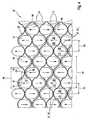
- the inventionis based on the general idea of implementing the mixer with the help of a corrugated sheeting of material that is stacked in several layers across the direction of flow such that cells through which the flow can pass in the direct flow direction are formed between neighboring layers.
- the sheeting materialis equipped with baffles that are arranged with an inclination with respect to the direction of flow on the outgoing flow end of several cells, preferably all cells.
- the corrugated sheeting materialcan be manufactured especially inexpensively.
- the mixershave a simple design so that the mixer can be implemented inexpensively.
- the individual cells with the baffles assigned in a predetermined mannerensure a targeted and thus intense vaporization effect and/or mixing effect.
- the pressure drop in flow through this mixercan be kept comparatively small due to the selected design with the flow-carrying cells.
- this mixerhas a relatively short design in the direction of flow.
- the corrugated form of the sheeting materialis uniformly selected so that the corrugations that occur have the same wavelength and the same amplitude. This simplifies inexpensive production of the sheeting material.
- the sheeting materialis arranged so that it is offset by one half wavelength across the direction of flow in each layer in comparison with the sheeting material of the next neighboring layer. Subsequently, the hills of the corrugations of one layer are in contact with the valleys of the corrugations of the neighboring layer, whereby the cells are formed between these contact points. In this configuration, the cells have maximum flow cross sections, which is advantageous with regard to a low flow resistance.
- the corrugations of the sheeting materialare sinusoidal, so that the sheeting material which is arranged layer by layer has a particularly high flexibility across the direction of flow. This presupposes the use of a suitably flexible material. In applications in exhaust systems, steels, especially stainless steels, may be used.
- the corrugations of the sheeting materialsmay be rectangular, which makes it possible to implement cells having a rectangular cross section.
- trapezoidal wave structuresmay also have a hexagonal and/or honeycomb cross section.
- Yet another embodimenthas the sheeting material which extends without interruption over at least two neighboring layers, and may also extend over all layers.
- the sheeting materialis then folded or bent over into the neighboring layer on the lateral ends of the respective layer.
- a wall structure constructed with the help of the layered sheeting materialcan thus be manufactured from just a single component, so that production of this wall structure and therefore of the mixer is extremely inexpensive.
- the bafflesmay be shaped integrally on the sheeting material in particular, dimensioned and oriented with respect to the direction of flow so that they seal and/or overlap the cells in the direction of flow at least 80% or at least 90% or at least 95% or 100% in a completely lightproof manner. Due to this design, it is possible to achieve an intense mixing and/or complete evaporation. For example, this ensures that liquid droplets sprayed upstream from the mixer will strike the baffles with a very high probability and thus cannot flow through the mixer unhindered. As soon as the liquid adheres to the baffles, it is exposed to the exhaust flow and its vaporizing effect.
- FIG. 1 ais a simplified basic sectional view of an exhaust treatment device
- FIG. 1 bis a simplified basic sectional view of an exhaust system
- FIG. 2is a cross section through the exhaust gas treatment device and/or the exhaust system according to sectional lines II in FIGS. 1 a and/or 1 b;
- FIG. 3is an enlarged prospective detailed view of an oncoming flow side of a mixer
- FIG. 4is an enlarged detailed view in the direction of flow of the oncoming flow side of the mixer
- FIG. 5is an enlarged perspective detailed view of the outgoing flow side of the mixer
- FIG. 6is an enlarged view of a detail of the mixer across the direction of flow
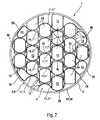
- FIG. 7is a cross-sectional view of another embodiment
- FIG. 8is a perspective view of the embodiment according to FIG. 7 ;
- FIG. 9is a longitudinal section of the mixer from FIG. 8 .
- an exhaust gas treatment device 1has a housing 2 with a tubular body 32 that forms a jacket of the housing 2 . At least one exhaust gas treatment insert 4 is arranged in the tubular body 32 .
- the exhaust gas treatment device 1is tied into an exhaust system 5 of an internal combustion engine (not shown).
- the exhaust gas treatment device 1may be a muffler, a particulate filter, a catalytic converter or any desired combination of the aforementioned devices.
- the exhaust gas treatment insert 4may be, for example, a catalytic converter element or a particulate filter element. Likewise, it may be a muffler arrangement.
- a static mixer 6is installed in the tubular body 32 and is explained in greater detail below with reference to FIGS. 2 through 9 .
- a spray nozzle 7arranged upstream from the mixer 6 , a liquid, represented by arrows 8 , can be sprayed into the exhaust gas flow, represented by arrows 9 , upstream from the mixer 6 .
- the liquid 8 sprayed into the exhaustmay be ammonia or an aqueous urea solution.
- the liquid sprayed into the exhaustmay be liquid fuel.
- the mixer 6 in the exhaust system 5 and/or in the exhaust gas treatment device 1serves to evaporate the liquid 8 sprayed into the device as extensively as possible and to mix it with the exhaust flow as thoroughly as possible to produce the most homogeneous possible fluid vapor-exhaust gas mixture downstream from the mixer 6 in this way.
- the mixer 6should have the most compact possible design to allow it to be integrated easily into such an exhaust gas treatment device 1 and/or exhaust system 5 .
- the exhaust system 5has an exhaust line 31 to which the exhaust gas treatment device 1 is connected.
- the mixer 6is situated in this exhaust line 31 namely upstream from the exhaust gas treatment device 1 .
- the spray device 7is in turn arranged upstream from the mixer 6 and is thus also mounted on the exhaust line 31 .
- This embodimentthus allows the use of a traditional exhaust gas treatment device 1 because the improved mixture is already produced upstream within the exhaust line 31 with the help of the mixer 6 .
- the static mixer 6has a wall structure 10 which is arranged across the direction of flow in the tubular body 32 ( FIG. 1 a ) and/or in the exhaust line 31 ( FIG. 1 b ).
- the tubular body 32 and/or the exhaust line 31each forms a pipe 3 into which the wall structure 10 is inserted.
- the pipe 3i.e., the tubular body 32 and/or the exhaust line 31 may have a fundamentally different cross section, depending on the particular installation situation. For example, circular, elliptical and rectangular cross sections are feasible.
- the wall structure 10is of such dimensions that it essentially fills up the cross section of the pipe 3 .
- the wall structure 10is composed of several layers 11 of a corrugated sheeting material 12 .
- the individual layers 11extend across the direction of flow and lie on top of one another across the direction of flow as well as across their own longitudinal direction.
- the sheeting material 12here is arranged in the individual layers 11 so that a plurality of cells 13 may be provided between the neighboring layers 11 next to the sheeting material 12 , each cell allowing flow to pass through it in the direction of flow.
- the sheeting material 12has one baffle 14 for multiple cells 13 , preferably for all cells 13 .
- These baffles 14are arranged on the sheeting material 12 in such a way that they are arranged on the outgoing flow side of the cells 13 described above. Then the baffles 14 extend in the direction of flow and also across the direction of flow, i.e., the baffles 14 are arranged so that they are opposite the direction of flow.
- the sheeting material 12may be manufactured with the uniform corrugations 15 (see FIG. 4 ) in all layers 11 , so that they have the same wavelengths 16 (see FIG. 4 ) and the same amplitudes 17 (see FIG. 4 ) in particular. Therefore, the same sheeting material 12 may be used to manufacture all layers 11 .
- the wall structure 10is expediently produced by arranging the sheeting material 12 so that it is offset by one half wavelength 16 across the direction of flow of neighboring layers 11 . Subsequently, the hills and valleys of the corrugations of neighboring layers 11 of the sheeting material 12 come in contact at contact points 18 (see FIGS. 3 , 4 and 7 ).
- the sheeting material 12is sinusoidal, i.e., with sinusoidal corrugations.
- the individual cells 13therefore have an essentially circular cross section.
- the corrugations 15 of the sheeting material 12may be rectangular or trapezoidal so that rectangular and/or hexagonal or honeycomb cross sections can be produced for the individual cells 13 .
- the sheeting material 12extends without interruption over at least two neighboring layers 11 .
- the sheeting material 12is bent or folded over into the respective next neighboring layer 11 on the lateral end of at least one layer 11 .
- the sheeting material 12may extend without interruption, i.e., in one piece over all layers 11 , as illustrated in FIG. 2 and FIG. 7 , for example.
- the sheeting material 12is then bent and/or folded over to the next neighboring layer 11 .
- the sheeting material 12 and/or the wall structure 10is encompassed by a ring 19 in the circumferential direction.
- the sheeting material 12is attached to this ring 19 .
- individual fastening points 20may be produced here, e.g., by welded points.
- the fastening points 20i.e., the welded spots may be distributed so that the sheeting material 12 is connected to the ring 19 in all layers 11 , at least on a lateral end of the respective layer 11 .
- the fastening points 20may also be formed by solder points.
- the wall structure 10i.e., the sheeting material 12 together with the ring 19 forms a unit which can be completely preassembled and inserted into the pipe 3 in the preassembled state.
- the ring 19may be slotted, e.g., at 22 .
- the ring 19can be compressed.
- a radial tensionmay be introduced into the ring 19 via the sheeting material 12 , said tension then attempting to widen the ring 19 .
- the ring 19 and thus the unit 21can compensate for the manufacturing tolerances.
- the ring 19is mounted on the pipe 3 and/or on the tubular body 3 of the exhaust gas treatment device 1 in a suitable manner, e.g., by axial contact with a step and/or by welding spots or soldered spots.
- the complete mixer 6may also be manufactured from only a single component, namely from the sheeting material 12 . If the ring 19 is optionally also provided, then the unit 21 may optionally consist only of these two components. This makes the manufacture of the mixer 6 comparatively inexpensive.
- the baffles 14may be arranged regularly along the sheeting material 12 in the advantageous embodiments illustrated here, namely in such a way that a repeating structure is formed within the sheeting material 12 .
- the individual baffles 14which protrude along the sheeting material 12 of successive orientations opposite one another with regard to the direction of flow.
- the baffles 14 which protrude away from the sheeting material 12 with the same orientations with regard to the direction of floware spaced a distance apart from one another by precisely two wavelengths 16 along the sheeting material 12 .
- the baffles 14 which protrude away from the sheeting material 12 with opposite orientations with respect to the direction of floware arranged so they are distributed along the sheeting material 12 so that they are spaced a distance of half a wavelength 16 apart in the direction of extent of the sheeting material 12 running across the direction of flow and are spaced a distance of three half-wavelengths 16 apart in the opposite direction of extent.
- baffles 14include a first exemplary pair 37 I of baffles and a second exemplary pair 37 II of baffles 14 .
- a first baffle 38 of pair 37 I and a first baffle 38 of second pair 37 IIare oriented in a downward direction with regard to the direction of flow
- a second baffle 39 of pair 37 I and a second baffle 39 of pair 37 IIare oriented in an upward direction with regard to the direction of flow.
- baffles 38 and 39protrude away from the sheeting material 12 with opposite orientation with respect to the direction of flow and are spaced apart by a distance 40 , which is equal to half a wavelength 16 .
- first baffle 38 of first pair 37 I and first baffle 38 of second pair 37 IIare spaced at a distance 41 which is equal to three half-wavelengths 16 . Due to the targeted arrangement of the sheeting material 12 within the layers 11 , it is possible to obtain the structure illustrated in FIGS. 3 through 5 in which the baffles 14 protrude away from the sheeting material 12 with opposing orientations with regard to the direction of flow with neighboring cells 13 formed between neighboring layers 11 . The arrangement of the baffles 14 selected here yields an intense mixing effect.
- the baffles 14 which protrude away from the sheeting material 12 with the same orientation with regard to the direction of floware spaced a distance apart from one another by exactly one wavelength 16 along the sheeting material 12 .
- the baffles 14 that protrude away from the sheeting material 12 with opposite orientations with regard to the direction of floware arranged along the sheeting material and are distributed so that they follow one another directly in the direction of extent of the sheeting material 12 across the direction of flow, i.e., being a distance of half a wavelength 16 from one another.
- the sheeting material 12is provided with the baffles 14 in each layer 11 , so in the embodiment illustrated in FIGS. 7 and 8 the wall structure 10 is such that layers 11 with baffles 14 alternate with layers 11 without baffles 14 .
- Layers 11 with baffles 14are designated by reference numeral 11 ′, whereas layers 11 without baffles 14 are designated by reference numeral 11 ′′.
- the baffles 14are arranged within the wall structure 10 with a distribution such that with neighboring cells 13 of neighboring layers 11 the baffles 14 protrude away from the sheeting material 12 with the same orientation with regard to the direction of flow.
- FIG. 7shows accordingly a vertical alignment of the cells 13 with the baffles 14 oriented in the same direction.
- the baffles 14are distributed within the wall structure only in such a way that with neighboring cells 13 of neighboring layers 11 the baffles protrude away from the sheeting material 12 with the opposite orientation with regard to the direction of flow. Accordingly this yields a structure of the cells 13 running diagonally with baffles 14 oriented in the same direction.
- the baffles 14may also cumulatively or alternatively implement the following features.
- the baffles 14may be angled by approximately 45° with respect to the direction of flow, alternately in one direction and in the other direction, as mentioned above. This is shown especially clearly in FIGS. 3 , 5 , 7 and 8 .
- the baffles 14are expediently of such dimensions and such an orientation with regard to the direction of flow which corresponds to the viewing direction in FIGS. 4 and 7 so that the individual cells 13 more or less overlap in the direction of flow and are therefore sealed in a more or less lightproof manner.
- the baffles 14achieve at least an 80% overlap or at least 90% overlap or at least a 95% overlap of the cells 13 in the direction of flow on the outgoing flow end, so the entire wall structure 10 is sealed at least 80%, 90% or 95% in the direction of flow to be lightproof.
- the baffles 14 according to FIG. 6may have a breakaway edge 24 on their respective outgoing flow end 23 or may be designed as such.
- the sheeting material 12may expediently be of such dimensions that in the individual cells 13 , the diameter 26 , measured across the direction of flow, may be greater than the length 27 measured in the direction of flow.
- the length 27 of the cells 13corresponds to the width 25 of the sheeting material 12 .
- the longitudinal extent 28 of the respective baffle 14is approximately equal to the length 27 of the respective cell 13 measured in the direction of flow.
- the baffles 14may each have a transverse extent 29 running across the direction of flow and being approximately equal to the diameter 26 of the respective cell 13 measured across the direction of flow. Essentially said transverse extent 29 corresponds to the respective baffle 14 , in particular half the wavelength 16 .
- the baffles 14may each have an oncoming flow side 30 having a convex curvature.
- said oncoming flow side 30may have a saddle-shaped curvature.
- the baffles 14 in the embodiment shown in FIG. 8may have oncoming flow sides 33 having a concave curvature.
- these oncoming flow sites 33may also have a saddle-shaped curvature.
- FIG. 8shows the preinstalled unit 21 which is equipped with the ring 19 and can be inserted as such into the respective pipe 3 .
- FIG. 8may also involve a detail of said pipe 3 , i.e., a detail of the exhaust gas treatment device 2 and/or the exhaust system 5 .
- Steel or steel platepreferably stainless steel, i.e., stainless steel plate is suitable as the material for the sheeting material 12 and optionally for the ring 19 .
- Possible steel alloysinclude, for example, alloys having the following European Standard numbers or EN numbers: 1.4509, 1.4435, 1.4512, 1.4438, 1.4513, 1.4541, 1.4522, 1.4571, 1.4301 and 1.4828.
- the baffles 14are preferably shaped in such a way that there is a steady transition to the direction of extent running across the direction of flow.
- the baffles 14therefore have a rounded soft transition with the largest possible radius. This achieves the result that any increase in backpressure in deflection of the flow remains as small as possible.
- voltage peaks in the wall structure 10can be reduced and the development of kinks and breaks and the development of cracks in thermal shock stress can be avoided.
Landscapes
- Chemical & Material Sciences (AREA)
- Chemical Kinetics & Catalysis (AREA)
- Engineering & Computer Science (AREA)
- Dispersion Chemistry (AREA)
- Combustion & Propulsion (AREA)
- Mechanical Engineering (AREA)
- General Engineering & Computer Science (AREA)
- Health & Medical Sciences (AREA)
- Toxicology (AREA)
- Exhaust Gas After Treatment (AREA)
- Exhaust Gas Treatment By Means Of Catalyst (AREA)
- Accessories For Mixers (AREA)
Abstract
Description
Claims (25)
Applications Claiming Priority (6)
| Application Number | Priority Date | Filing Date | Title |
|---|---|---|---|
| DEDE102006009676.2 | 2006-03-02 | ||
| DE102006009676 | 2006-03-02 | ||
| DE102006009676 | 2006-03-02 | ||
| DEDE102006024778.7 | 2006-05-27 | ||
| DE102006024778ADE102006024778B3 (en) | 2006-03-02 | 2006-05-27 | Static mixer for exhaust system of internal combustion engine, has flow conducting surfaces arranged at web materials so that surfaces are arranged with cells at their diverting side and extend in direction of flow in tube |
| DE102006024778 | 2006-05-27 |
Publications (2)
| Publication Number | Publication Date |
|---|---|
| US20070204751A1 US20070204751A1 (en) | 2007-09-06 |
| US7793494B2true US7793494B2 (en) | 2010-09-14 |
Family
ID=37908105
Family Applications (1)
| Application Number | Title | Priority Date | Filing Date |
|---|---|---|---|
| US11/604,957Expired - Fee RelatedUS7793494B2 (en) | 2006-03-02 | 2006-11-28 | Static mixer and exhaust gas treatment device |
Country Status (5)
| Country | Link |
|---|---|
| US (1) | US7793494B2 (en) |
| EP (1) | EP1830042B1 (en) |
| JP (1) | JP5059447B2 (en) |
| CN (1) | CN101029590B (en) |
| DE (2) | DE102006024778B3 (en) |
Cited By (88)
| Publication number | Priority date | Publication date | Assignee | Title |
|---|---|---|---|---|
| US20080066448A1 (en)* | 2006-09-11 | 2008-03-20 | J. Eberspaecher Gmbh & Co. Kg | Exhaust gas system for an internal combustion engine |
| US20090255242A1 (en)* | 2008-04-09 | 2009-10-15 | Woodward Governor Company | Low Pressure Drop Mixer for Radial Mixing of Internal Combustion Engine Exhaust Flows, Combustor Incorporating Same, and Methods of Mixing |
| US20100218490A1 (en)* | 2007-02-28 | 2010-09-02 | Emcon Technologies Germany (Augsburg) Gmbh | Static mixing element and method of producing a static mixing element |
| US8017084B1 (en)* | 2008-06-11 | 2011-09-13 | Callidus Technologies, L.L.C. | Ammonia injection grid for a selective catalytic reduction system |
| US20130074480A1 (en)* | 2011-09-28 | 2013-03-28 | J. Eberspächer GmbH & Co. KG | Mixing and/or evaporating device |
| US20130199647A1 (en)* | 2012-02-03 | 2013-08-08 | Alstom Technology Ltd | Arrangement for supplying a reducing agent in gaseous form into a flue gas |
| US8635858B2 (en) | 2011-10-25 | 2014-01-28 | Ford Global Technologies, Llc | Fluid-spray atomizer |
| US8734545B2 (en) | 2008-03-28 | 2014-05-27 | Exxonmobil Upstream Research Company | Low emission power generation and hydrocarbon recovery systems and methods |
| US8984857B2 (en) | 2008-03-28 | 2015-03-24 | Exxonmobil Upstream Research Company | Low emission power generation and hydrocarbon recovery systems and methods |
| US9027321B2 (en) | 2008-03-28 | 2015-05-12 | Exxonmobil Upstream Research Company | Low emission power generation and hydrocarbon recovery systems and methods |
| US9222671B2 (en) | 2008-10-14 | 2015-12-29 | Exxonmobil Upstream Research Company | Methods and systems for controlling the products of combustion |
| US9353682B2 (en) | 2012-04-12 | 2016-05-31 | General Electric Company | Methods, systems and apparatus relating to combustion turbine power plants with exhaust gas recirculation |
| US9463417B2 (en) | 2011-03-22 | 2016-10-11 | Exxonmobil Upstream Research Company | Low emission power generation systems and methods incorporating carbon dioxide separation |
| US9512759B2 (en) | 2013-02-06 | 2016-12-06 | General Electric Company | System and method for catalyst heat utilization for gas turbine with exhaust gas recirculation |
| US9574496B2 (en) | 2012-12-28 | 2017-02-21 | General Electric Company | System and method for a turbine combustor |
| US9581081B2 (en) | 2013-01-13 | 2017-02-28 | General Electric Company | System and method for protecting components in a gas turbine engine with exhaust gas recirculation |
| US9587510B2 (en) | 2013-07-30 | 2017-03-07 | General Electric Company | System and method for a gas turbine engine sensor |
| US9599021B2 (en) | 2011-03-22 | 2017-03-21 | Exxonmobil Upstream Research Company | Systems and methods for controlling stoichiometric combustion in low emission turbine systems |
| US9599070B2 (en) | 2012-11-02 | 2017-03-21 | General Electric Company | System and method for oxidant compression in a stoichiometric exhaust gas recirculation gas turbine system |
| US9611756B2 (en) | 2012-11-02 | 2017-04-04 | General Electric Company | System and method for protecting components in a gas turbine engine with exhaust gas recirculation |
| US9618261B2 (en) | 2013-03-08 | 2017-04-11 | Exxonmobil Upstream Research Company | Power generation and LNG production |
| US9617914B2 (en) | 2013-06-28 | 2017-04-11 | General Electric Company | Systems and methods for monitoring gas turbine systems having exhaust gas recirculation |
| US9631815B2 (en) | 2012-12-28 | 2017-04-25 | General Electric Company | System and method for a turbine combustor |
| US9631542B2 (en) | 2013-06-28 | 2017-04-25 | General Electric Company | System and method for exhausting combustion gases from gas turbine engines |
| US9638138B2 (en) | 2015-03-09 | 2017-05-02 | Caterpillar Inc. | Turbocharger and method |
| US9650913B2 (en) | 2015-03-09 | 2017-05-16 | Caterpillar Inc. | Turbocharger turbine containment structure |
| US9670841B2 (en) | 2011-03-22 | 2017-06-06 | Exxonmobil Upstream Research Company | Methods of varying low emission turbine gas recycle circuits and systems and apparatus related thereto |
| US9683520B2 (en) | 2015-03-09 | 2017-06-20 | Caterpillar Inc. | Turbocharger and method |
| US9689309B2 (en) | 2011-03-22 | 2017-06-27 | Exxonmobil Upstream Research Company | Systems and methods for carbon dioxide capture in low emission combined turbine systems |
| US9708977B2 (en) | 2012-12-28 | 2017-07-18 | General Electric Company | System and method for reheat in gas turbine with exhaust gas recirculation |
| US9732673B2 (en) | 2010-07-02 | 2017-08-15 | Exxonmobil Upstream Research Company | Stoichiometric combustion with exhaust gas recirculation and direct contact cooler |
| US9732633B2 (en) | 2015-03-09 | 2017-08-15 | Caterpillar Inc. | Turbocharger turbine assembly |
| US9732675B2 (en) | 2010-07-02 | 2017-08-15 | Exxonmobil Upstream Research Company | Low emission power generation systems and methods |
| US9739238B2 (en) | 2015-03-09 | 2017-08-22 | Caterpillar Inc. | Turbocharger and method |
| US9752536B2 (en) | 2015-03-09 | 2017-09-05 | Caterpillar Inc. | Turbocharger and method |
| US9752458B2 (en) | 2013-12-04 | 2017-09-05 | General Electric Company | System and method for a gas turbine engine |
| US9777747B2 (en) | 2015-03-09 | 2017-10-03 | Caterpillar Inc. | Turbocharger with dual-use mounting holes |
| US9784182B2 (en) | 2013-03-08 | 2017-10-10 | Exxonmobil Upstream Research Company | Power generation and methane recovery from methane hydrates |
| US9784185B2 (en) | 2012-04-26 | 2017-10-10 | General Electric Company | System and method for cooling a gas turbine with an exhaust gas provided by the gas turbine |
| US9784140B2 (en) | 2013-03-08 | 2017-10-10 | Exxonmobil Upstream Research Company | Processing exhaust for use in enhanced oil recovery |
| US9803865B2 (en) | 2012-12-28 | 2017-10-31 | General Electric Company | System and method for a turbine combustor |
| US9810238B2 (en) | 2015-03-09 | 2017-11-07 | Caterpillar Inc. | Turbocharger with turbine shroud |
| US9810050B2 (en) | 2011-12-20 | 2017-11-07 | Exxonmobil Upstream Research Company | Enhanced coal-bed methane production |
| US9819292B2 (en) | 2014-12-31 | 2017-11-14 | General Electric Company | Systems and methods to respond to grid overfrequency events for a stoichiometric exhaust recirculation gas turbine |
| US9822688B2 (en)* | 2015-06-24 | 2017-11-21 | Ford Global Technologies, Llc | Exhaust flow device |
| US9822700B2 (en) | 2015-03-09 | 2017-11-21 | Caterpillar Inc. | Turbocharger with oil containment arrangement |
| US9835089B2 (en) | 2013-06-28 | 2017-12-05 | General Electric Company | System and method for a fuel nozzle |
| US9863267B2 (en) | 2014-01-21 | 2018-01-09 | General Electric Company | System and method of control for a gas turbine engine |
| US9869247B2 (en) | 2014-12-31 | 2018-01-16 | General Electric Company | Systems and methods of estimating a combustion equivalence ratio in a gas turbine with exhaust gas recirculation |
| US9869279B2 (en) | 2012-11-02 | 2018-01-16 | General Electric Company | System and method for a multi-wall turbine combustor |
| US9879594B2 (en) | 2015-03-09 | 2018-01-30 | Caterpillar Inc. | Turbocharger turbine nozzle and containment structure |
| US9885290B2 (en) | 2014-06-30 | 2018-02-06 | General Electric Company | Erosion suppression system and method in an exhaust gas recirculation gas turbine system |
| US9890788B2 (en) | 2015-03-09 | 2018-02-13 | Caterpillar Inc. | Turbocharger and method |
| US9903225B2 (en) | 2015-03-09 | 2018-02-27 | Caterpillar Inc. | Turbocharger with low carbon steel shaft |
| US9903588B2 (en) | 2013-07-30 | 2018-02-27 | General Electric Company | System and method for barrier in passage of combustor of gas turbine engine with exhaust gas recirculation |
| US9903271B2 (en) | 2010-07-02 | 2018-02-27 | Exxonmobil Upstream Research Company | Low emission triple-cycle power generation and CO2 separation systems and methods |
| US9903316B2 (en) | 2010-07-02 | 2018-02-27 | Exxonmobil Upstream Research Company | Stoichiometric combustion of enriched air with exhaust gas recirculation |
| US9915200B2 (en) | 2014-01-21 | 2018-03-13 | General Electric Company | System and method for controlling the combustion process in a gas turbine operating with exhaust gas recirculation |
| US9915172B2 (en) | 2015-03-09 | 2018-03-13 | Caterpillar Inc. | Turbocharger with bearing piloted compressor wheel |
| US9932874B2 (en) | 2013-02-21 | 2018-04-03 | Exxonmobil Upstream Research Company | Reducing oxygen in a gas turbine exhaust |
| US9938861B2 (en) | 2013-02-21 | 2018-04-10 | Exxonmobil Upstream Research Company | Fuel combusting method |
| US9951658B2 (en) | 2013-07-31 | 2018-04-24 | General Electric Company | System and method for an oxidant heating system |
| US10006341B2 (en) | 2015-03-09 | 2018-06-26 | Caterpillar Inc. | Compressor assembly having a diffuser ring with tabs |
| US10012151B2 (en) | 2013-06-28 | 2018-07-03 | General Electric Company | Systems and methods for controlling exhaust gas flow in exhaust gas recirculation gas turbine systems |
| US10030588B2 (en) | 2013-12-04 | 2018-07-24 | General Electric Company | Gas turbine combustor diagnostic system and method |
| US10047633B2 (en) | 2014-05-16 | 2018-08-14 | General Electric Company | Bearing housing |
| US10060359B2 (en) | 2014-06-30 | 2018-08-28 | General Electric Company | Method and system for combustion control for gas turbine system with exhaust gas recirculation |
| US10066639B2 (en) | 2015-03-09 | 2018-09-04 | Caterpillar Inc. | Compressor assembly having a vaneless space |
| US10079564B2 (en) | 2014-01-27 | 2018-09-18 | General Electric Company | System and method for a stoichiometric exhaust gas recirculation gas turbine system |
| US10094566B2 (en) | 2015-02-04 | 2018-10-09 | General Electric Company | Systems and methods for high volumetric oxidant flow in gas turbine engine with exhaust gas recirculation |
| US10100741B2 (en) | 2012-11-02 | 2018-10-16 | General Electric Company | System and method for diffusion combustion with oxidant-diluent mixing in a stoichiometric exhaust gas recirculation gas turbine system |
| US10107495B2 (en) | 2012-11-02 | 2018-10-23 | General Electric Company | Gas turbine combustor control system for stoichiometric combustion in the presence of a diluent |
| US10145269B2 (en) | 2015-03-04 | 2018-12-04 | General Electric Company | System and method for cooling discharge flow |
| US10208677B2 (en) | 2012-12-31 | 2019-02-19 | General Electric Company | Gas turbine load control system |
| US10215412B2 (en) | 2012-11-02 | 2019-02-26 | General Electric Company | System and method for load control with diffusion combustion in a stoichiometric exhaust gas recirculation gas turbine system |
| US10221762B2 (en) | 2013-02-28 | 2019-03-05 | General Electric Company | System and method for a turbine combustor |
| US10227920B2 (en) | 2014-01-15 | 2019-03-12 | General Electric Company | Gas turbine oxidant separation system |
| US10253690B2 (en) | 2015-02-04 | 2019-04-09 | General Electric Company | Turbine system with exhaust gas recirculation, separation and extraction |
| US10267270B2 (en) | 2015-02-06 | 2019-04-23 | General Electric Company | Systems and methods for carbon black production with a gas turbine engine having exhaust gas recirculation |
| US10273880B2 (en) | 2012-04-26 | 2019-04-30 | General Electric Company | System and method of recirculating exhaust gas for use in a plurality of flow paths in a gas turbine engine |
| US10315150B2 (en) | 2013-03-08 | 2019-06-11 | Exxonmobil Upstream Research Company | Carbon dioxide recovery |
| US10316746B2 (en) | 2015-02-04 | 2019-06-11 | General Electric Company | Turbine system with exhaust gas recirculation, separation and extraction |
| US10480792B2 (en) | 2015-03-06 | 2019-11-19 | General Electric Company | Fuel staging in a gas turbine engine |
| US10655542B2 (en) | 2014-06-30 | 2020-05-19 | General Electric Company | Method and system for startup of gas turbine system drive trains with exhaust gas recirculation |
| US10788212B2 (en) | 2015-01-12 | 2020-09-29 | General Electric Company | System and method for an oxidant passageway in a gas turbine system with exhaust gas recirculation |
| US10898872B2 (en) | 2015-11-13 | 2021-01-26 | Re Mixers, Inc. | Static mixer |
| US10941692B1 (en)* | 2019-11-01 | 2021-03-09 | Tenneco Automotive Operating Company Inc. | Mixer assembly for exhaust aftertreatment system |
| US12383875B2 (en) | 2019-10-21 | 2025-08-12 | Re Mixers, Inc | Static mixer |
Families Citing this family (63)
| Publication number | Priority date | Publication date | Assignee | Title |
|---|---|---|---|---|
| DE102006055036B4 (en) | 2006-11-22 | 2023-03-02 | Faurecia Emissions Control Technologies, Germany Gmbh | Mixing element and exhaust system for an internal combustion engine |
| JP5244334B2 (en)* | 2007-05-01 | 2013-07-24 | 三菱ふそうトラック・バス株式会社 | Exhaust gas purification device for internal combustion engine |
| JP4404123B2 (en)* | 2007-09-07 | 2010-01-27 | トヨタ自動車株式会社 | Additive dispersion plate structure in exhaust passage |
| JP4375465B2 (en)* | 2007-09-14 | 2009-12-02 | トヨタ自動車株式会社 | Additive dispersion plate structure in exhaust passage |
| JP4600457B2 (en)* | 2007-10-02 | 2010-12-15 | トヨタ自動車株式会社 | Additive dispersion plate structure in exhaust passage |
| DE102007048558A1 (en)* | 2007-10-09 | 2009-04-16 | Audi Ag | Static mixer for an exhaust system of an internal combustion engine-driven vehicle, in particular of a motor vehicle |
| US8230957B2 (en)* | 2008-01-30 | 2012-07-31 | Deere & Company | Flow-inducing baffle for engine compartment ventilation |
| DE102008028626B4 (en) | 2008-04-21 | 2011-05-19 | Heinrich Gillet Gmbh | mixer |
| DE102008028625B4 (en) | 2008-04-21 | 2011-12-15 | Tenneco Gmbh | Method for mixing an exhaust gas stream |
| DE102008028627A1 (en) | 2008-04-21 | 2009-10-22 | Heinrich Gillet Gmbh | mixing element |
| US8939638B2 (en) | 2008-04-21 | 2015-01-27 | Tenneco Automotive Operating Company Inc. | Method for mixing an exhaust gas flow |
| US8272777B2 (en) | 2008-04-21 | 2012-09-25 | Heinrich Gillet Gmbh (Tenneco) | Method for mixing an exhaust gas flow |
| US9095827B2 (en) | 2008-04-21 | 2015-08-04 | Tenneco Automotive Operating Company Inc. | Exhaust gas flow mixer |
| US8141353B2 (en)* | 2008-04-25 | 2012-03-27 | Tenneco Automotive Operating Company Inc. | Exhaust gas additive/treatment system and mixer for use therein |
| DE102008020827A1 (en) | 2008-04-25 | 2009-11-05 | Presswerk Struthütten GmbH | Mixer, method of making such and mixer assembly |
| DE102008026724B4 (en) | 2008-06-04 | 2013-11-28 | KÖNIG METALL GmbH & Co. KG | Closure for a pipe or a circuit board |
| CN102159810B (en)* | 2008-09-19 | 2013-11-13 | 雷诺卡车公司 | Mixing device in the exhaust pipe |
| DE102008052757B4 (en)* | 2008-10-22 | 2014-02-20 | Eberspächer Exhaust Technology GmbH & Co. KG | Device for introducing a liquid into an exhaust gas flow |
| US9429058B2 (en)* | 2008-12-01 | 2016-08-30 | GM Global Technology Operations LLC | Mixing devices for selective catalytic reduction systems |
| US8869518B2 (en)* | 2009-09-15 | 2014-10-28 | Tenneco Automotive Operating Company Inc. | Burner for a diesel aftertreatment system |
| US8683790B2 (en)* | 2009-11-10 | 2014-04-01 | GM Global Technology Operations LLC | Nozzle diffuser mixer |
| US8359832B2 (en)* | 2009-12-21 | 2013-01-29 | Caterpillar Inc. | SCR reductant mixer |
| CN102242662B (en)* | 2010-05-10 | 2012-12-19 | 杭州银轮科技有限公司 | Static mixer of selective catalytic reduction (SCR) denitration system |
| KR101664494B1 (en)* | 2010-07-08 | 2016-10-13 | 두산인프라코어 주식회사 | Static mixer for mixing urea aqueous solution and engine exhaust gas |
| US9605577B2 (en) | 2010-07-15 | 2017-03-28 | Ford Global Technologies, Llc | Exhaust passage |
| EP2433701A1 (en)* | 2010-09-27 | 2012-03-28 | Alstom Technology Ltd | Gas flow control arrangement |
| IT1403427B1 (en) | 2010-12-23 | 2013-10-17 | Metallurg G Cornaglia Spa Off | STATIC MIXER FOR THE TREATMENT OF EXHAUST GAS AND ITS MANUFACTURING METHOD |
| CN102172485B (en)* | 2011-03-25 | 2013-06-12 | 天津华迈环保设备有限公司 | Spraying-type fluid mixing device |
| ITTO20110535A1 (en) | 2011-06-20 | 2012-12-21 | Cornaglia G Off Met Spa | STATIC MIXER FOR THE TREATMENT OF EXHAUST GAS AND ITS MANUFACTURING METHOD. |
| RU2467791C1 (en)* | 2011-09-02 | 2012-11-27 | Владимир Леонидович Письменный | Cellular mixer |
| CN102343226A (en)* | 2011-09-08 | 2012-02-08 | 富阳亨特气体设备有限公司 | Air flow distributor |
| DE102011089969B4 (en)* | 2011-12-27 | 2015-05-21 | Eberspächer Exhaust Technology GmbH & Co. KG | Exhaust treatment device |
| GB201207201D0 (en)* | 2012-04-24 | 2012-06-06 | Perkins Engines Co Ltd | Emissions cleaning module for a diesel engine |
| WO2014022386A2 (en)* | 2012-07-31 | 2014-02-06 | Cummins Filtration Ip, Inc. | Methods and apparatuses for separating liquid particles from a gas-liquid stream |
| KR101696203B1 (en) | 2012-08-10 | 2017-01-13 | 테네코 오토모티브 오퍼레이팅 컴파니 인코포레이티드 | Method for mixing an exhaust gas flow |
| DE102012216923B4 (en)* | 2012-09-20 | 2016-01-28 | Eberspächer Exhaust Technology GmbH & Co. KG | Exhaust system for a motor vehicle |
| CN103899389B (en)* | 2012-12-24 | 2018-02-06 | 福特汽车萨纳伊股份有限公司 | Static mixer |
| USD704228S1 (en)* | 2013-10-11 | 2014-05-06 | Kenneth Richard | Catalytic converter exhaust trap |
| USD704747S1 (en)* | 2013-10-11 | 2014-05-13 | Kenneth Richard | Catalytic converter exhaust trap |
| USD704745S1 (en)* | 2013-10-11 | 2014-05-13 | Kenneth Richard | Catalytic converter exhaust trap |
| USD704746S1 (en)* | 2013-10-11 | 2014-05-13 | Kenneth Richard | Catalytic converter exhaust trap |
| USD705270S1 (en)* | 2013-10-11 | 2014-05-20 | Kenneth Richard | Catalytic converter exhaust trap |
| DE112014005413B4 (en)* | 2013-11-26 | 2019-08-29 | Tenneco Automotive Operating Company Inc. | Exhaust flow mixer |
| ES2674557T3 (en) | 2014-08-13 | 2018-07-02 | Officine Metallurgiche G. Cornaglia S.P.A. | Dynamic mixer with mobile blades for exhaust gases of internal combustion engines |
| US10119447B2 (en)* | 2014-10-15 | 2018-11-06 | Acat Global | Exhaust system and device to induce improved exhaust gas mixing prior to treatment through a catalytic converter |
| CN104791050A (en)* | 2015-03-04 | 2015-07-22 | 刘君才 | Static mixer type automobile exhaust filtering/silencing device |
| US9534525B2 (en) | 2015-05-27 | 2017-01-03 | Tenneco Automotive Operating Company Inc. | Mixer assembly for exhaust aftertreatment system |
| US10113468B2 (en) | 2015-07-17 | 2018-10-30 | Middleville Tool & Die Co. | Mixer assembly for exhaust systems and method of forming the same |
| CN105107272B (en)* | 2015-09-10 | 2017-06-16 | 中国石油大学(北京) | A kind of structure improved method for improving corrugated plating separative efficiency |
| US10092878B2 (en)* | 2016-03-03 | 2018-10-09 | General Electric Company | System and method for mixing tempering air with flue gas for hot SCR catalyst |
| US11273419B2 (en)* | 2016-10-05 | 2022-03-15 | Covestro Deutschland Ag | Mixing elements with a reduced structural depth for static mixers |
| KR101913030B1 (en)* | 2017-03-24 | 2018-10-29 | 두산중공업 주식회사 | Static mixer and fluid mixing structure including the same |
| IT201800007427A1 (en) | 2018-07-23 | 2020-01-23 | Static mixer for exhaust gas ducts of endothermic engines, its method of construction and exhaust group that incorporates the mixer. | |
| KR102727900B1 (en)* | 2019-05-02 | 2024-11-07 | 현대자동차주식회사 | Exhaust system for vehicle |
| CN111617649A (en)* | 2020-05-06 | 2020-09-04 | 酒泉顺鑫气体股份有限公司 | Novel gas mixer and use method |
| USD992691S1 (en)* | 2020-12-18 | 2023-07-18 | Commonwealth Scientific And Industrial Research Organisation | Static mixer |
| USD1008418S1 (en)* | 2020-12-18 | 2023-12-19 | Commonwealth Scientific And Industrial Research Organisation | Static mixer |
| USD1008485S1 (en)* | 2020-12-18 | 2023-12-19 | Commonwealth Scientific And Industrial Research Organisation | Static mixer |
| USD1009216S1 (en)* | 2020-12-18 | 2023-12-26 | Commonwealth Scientific And Industrial Research Organisation | Static mixer |
| USD1009221S1 (en)* | 2020-12-18 | 2023-12-26 | Commonwealth Scientific And Industrial Research Organisation | Static mixer |
| USD1008417S1 (en)* | 2020-12-18 | 2023-12-19 | Commonwealth Scientific And Industrial Research Organisation | Static mixer |
| USD1009222S1 (en)* | 2020-12-18 | 2023-12-26 | Commonwealth Scientific And Industrial Research Organisation | Static mixer |
| CN120571399B (en)* | 2025-08-01 | 2025-10-03 | 包头市森都新材料有限公司 | System and method for purifying tail gas of prebaked anode roasting kiln |
Citations (15)
| Publication number | Priority date | Publication date | Assignee | Title |
|---|---|---|---|---|
| DD161209A1 (en) | 1981-09-25 | 1985-06-12 | Adw Ddr | DEVICE FOR STATIC MIXING FLUIDER MEDIA |
| US4530418A (en) | 1982-06-01 | 1985-07-23 | Currie Neil L | Automotive exhaust system |
| US4824614A (en)* | 1987-04-09 | 1989-04-25 | Santa Fe Energy Company | Device for uniformly distributing a two-phase fluid |
| DE4109305A1 (en) | 1991-03-21 | 1992-09-24 | Siemens Ag | Reagent injection to process or flue gas stream - e.g. for ammonia addition in catalytic nitrogen oxide(s) redn. of stack gases |
| DE4123161A1 (en) | 1991-07-12 | 1993-01-14 | Siemens Ag | STATIC MIXER |
| EP0894523A1 (en)* | 1997-07-28 | 1999-02-03 | Siemens Aktiengesellschaft | Static mixer and exhaust duct for a combustion system |
| DE19741199C2 (en) | 1997-09-18 | 2000-10-26 | Siemens Ag | Static mixer |
| USRE36969E (en) | 1991-07-30 | 2000-11-28 | Sulzer Brothers Limited | Static mixing element having deflectors and a mixing device |
| DE10020170C1 (en) | 2000-04-25 | 2001-09-06 | Emitec Emissionstechnologie | Process for removing soot particles from the exhaust gas of internal combustion engine comprises feeding gas through collecting element, and holding and/or fluidizing until there is sufficient reaction with nitrogen dioxide in exhaust gas |
| US6401800B1 (en) | 1998-05-28 | 2002-06-11 | Daimlerchrysler Ag | Device and method for continuous casting of workpieces |
| US20020108368A1 (en) | 1999-08-17 | 2002-08-15 | Jan Hodgson | Device for reducing a level of nitrogen oxides in an exhaust gas of an internal combustion engine |
| DE4313393C2 (en) | 1993-04-07 | 2003-06-26 | Siemens Ag | Static mixer |
| EP1371824A1 (en) | 2002-06-11 | 2003-12-17 | Siemens Aktiengesellschaft | Device for purifying exhaust gas of a combustion system |
| WO2005064131A1 (en) | 2003-12-25 | 2005-07-14 | Toyota Jidosha Kabushiki Kaisha | Apparatus for purifying exhaust gas |
| WO2005075837A1 (en) | 2004-02-09 | 2005-08-18 | Indigo Technologies Group Pty Ltd | Improved particle interactions in a fluid flow |
Family Cites Families (6)
| Publication number | Priority date | Publication date | Assignee | Title |
|---|---|---|---|---|
| JPS648926U (en)* | 1987-07-07 | 1989-01-18 | ||
| DE3733402A1 (en)* | 1987-10-02 | 1989-04-13 | Emitec Emissionstechnologie | CATALYST ARRANGEMENT WITH FLOW GUIDE |
| JPH074230A (en)* | 1993-02-24 | 1995-01-10 | Nippon Soken Inc | Electric heating type catalytic device |
| JPH08312338A (en)* | 1995-05-11 | 1996-11-26 | Usui Internatl Ind Co Ltd | Exhaust emission control device |
| US6401499B1 (en)* | 2000-07-31 | 2002-06-11 | Maytag Corporation | Air pump bulk dispenser |
| DE102004027907A1 (en)* | 2004-06-09 | 2005-12-29 | Emitec Gesellschaft Für Emissionstechnologie Mbh | Control system for a mobile internal combustion engine |
- 2006
- 2006-05-27DEDE102006024778Apatent/DE102006024778B3/ennot_activeExpired - Fee Related
- 2006-11-09DEDE502006008762Tpatent/DE502006008762D1/enactiveActive
- 2006-11-09EPEP06123722Apatent/EP1830042B1/ennot_activeNot-in-force
- 2006-11-28USUS11/604,957patent/US7793494B2/ennot_activeExpired - Fee Related
- 2006-12-12CNCN2006101658269Apatent/CN101029590B/ennot_activeExpired - Fee Related
- 2007
- 2007-02-28JPJP2007048508Apatent/JP5059447B2/ennot_activeExpired - Fee Related
Patent Citations (19)
| Publication number | Priority date | Publication date | Assignee | Title |
|---|---|---|---|---|
| DD161209A1 (en) | 1981-09-25 | 1985-06-12 | Adw Ddr | DEVICE FOR STATIC MIXING FLUIDER MEDIA |
| US4530418A (en) | 1982-06-01 | 1985-07-23 | Currie Neil L | Automotive exhaust system |
| US4824614A (en)* | 1987-04-09 | 1989-04-25 | Santa Fe Energy Company | Device for uniformly distributing a two-phase fluid |
| DE4109305A1 (en) | 1991-03-21 | 1992-09-24 | Siemens Ag | Reagent injection to process or flue gas stream - e.g. for ammonia addition in catalytic nitrogen oxide(s) redn. of stack gases |
| US5435976A (en) | 1991-03-21 | 1995-07-25 | Siemens Aktiengesellschaft | Device for introducing a reactant into a gas flow |
| DE4123161A1 (en) | 1991-07-12 | 1993-01-14 | Siemens Ag | STATIC MIXER |
| USRE36969E (en) | 1991-07-30 | 2000-11-28 | Sulzer Brothers Limited | Static mixing element having deflectors and a mixing device |
| DE4313393C2 (en) | 1993-04-07 | 2003-06-26 | Siemens Ag | Static mixer |
| EP0894523A1 (en)* | 1997-07-28 | 1999-02-03 | Siemens Aktiengesellschaft | Static mixer and exhaust duct for a combustion system |
| EP0894523B1 (en) | 1997-07-28 | 2003-10-01 | Siemens Aktiengesellschaft | Use of a static mixer as catalyst for hydrolysis and the use thereof for an exhaust duct for a combustion system |
| DE19741199C2 (en) | 1997-09-18 | 2000-10-26 | Siemens Ag | Static mixer |
| US6401800B1 (en) | 1998-05-28 | 2002-06-11 | Daimlerchrysler Ag | Device and method for continuous casting of workpieces |
| US20020108368A1 (en) | 1999-08-17 | 2002-08-15 | Jan Hodgson | Device for reducing a level of nitrogen oxides in an exhaust gas of an internal combustion engine |
| DE19938854C5 (en) | 1999-08-17 | 2006-12-28 | Emitec Gesellschaft Für Emissionstechnologie Mbh | Device for reducing the nitrogen oxide content in an exhaust gas of an internal combustion engine |
| DE10020170C1 (en) | 2000-04-25 | 2001-09-06 | Emitec Emissionstechnologie | Process for removing soot particles from the exhaust gas of internal combustion engine comprises feeding gas through collecting element, and holding and/or fluidizing until there is sufficient reaction with nitrogen dioxide in exhaust gas |
| US20030072694A1 (en) | 2000-04-25 | 2003-04-17 | Jan Hodgson | Method for removing soot particles from an exhaust gas, associated collecting element and system |
| EP1371824A1 (en) | 2002-06-11 | 2003-12-17 | Siemens Aktiengesellschaft | Device for purifying exhaust gas of a combustion system |
| WO2005064131A1 (en) | 2003-12-25 | 2005-07-14 | Toyota Jidosha Kabushiki Kaisha | Apparatus for purifying exhaust gas |
| WO2005075837A1 (en) | 2004-02-09 | 2005-08-18 | Indigo Technologies Group Pty Ltd | Improved particle interactions in a fluid flow |
Cited By (104)
| Publication number | Priority date | Publication date | Assignee | Title |
|---|---|---|---|---|
| US7975472B2 (en)* | 2006-09-11 | 2011-07-12 | J. Eberspaecher Gmbh & Co. Kg | Exhaust gas system for an internal combustion engine |
| US20080066448A1 (en)* | 2006-09-11 | 2008-03-20 | J. Eberspaecher Gmbh & Co. Kg | Exhaust gas system for an internal combustion engine |
| US20100218490A1 (en)* | 2007-02-28 | 2010-09-02 | Emcon Technologies Germany (Augsburg) Gmbh | Static mixing element and method of producing a static mixing element |
| US8375708B2 (en)* | 2007-02-28 | 2013-02-19 | Emcon Technologies Germany (Augsburg) Gmbh | Static mixing element and method of producing a static mixing element |
| US8734545B2 (en) | 2008-03-28 | 2014-05-27 | Exxonmobil Upstream Research Company | Low emission power generation and hydrocarbon recovery systems and methods |
| US9027321B2 (en) | 2008-03-28 | 2015-05-12 | Exxonmobil Upstream Research Company | Low emission power generation and hydrocarbon recovery systems and methods |
| US8984857B2 (en) | 2008-03-28 | 2015-03-24 | Exxonmobil Upstream Research Company | Low emission power generation and hydrocarbon recovery systems and methods |
| US20090255242A1 (en)* | 2008-04-09 | 2009-10-15 | Woodward Governor Company | Low Pressure Drop Mixer for Radial Mixing of Internal Combustion Engine Exhaust Flows, Combustor Incorporating Same, and Methods of Mixing |
| US8459017B2 (en)* | 2008-04-09 | 2013-06-11 | Woodward, Inc. | Low pressure drop mixer for radial mixing of internal combustion engine exhaust flows, combustor incorporating same, and methods of mixing |
| US8017084B1 (en)* | 2008-06-11 | 2011-09-13 | Callidus Technologies, L.L.C. | Ammonia injection grid for a selective catalytic reduction system |
| US10495306B2 (en) | 2008-10-14 | 2019-12-03 | Exxonmobil Upstream Research Company | Methods and systems for controlling the products of combustion |
| US9222671B2 (en) | 2008-10-14 | 2015-12-29 | Exxonmobil Upstream Research Company | Methods and systems for controlling the products of combustion |
| US9719682B2 (en) | 2008-10-14 | 2017-08-01 | Exxonmobil Upstream Research Company | Methods and systems for controlling the products of combustion |
| US9903271B2 (en) | 2010-07-02 | 2018-02-27 | Exxonmobil Upstream Research Company | Low emission triple-cycle power generation and CO2 separation systems and methods |
| US9732673B2 (en) | 2010-07-02 | 2017-08-15 | Exxonmobil Upstream Research Company | Stoichiometric combustion with exhaust gas recirculation and direct contact cooler |
| US9903316B2 (en) | 2010-07-02 | 2018-02-27 | Exxonmobil Upstream Research Company | Stoichiometric combustion of enriched air with exhaust gas recirculation |
| US9732675B2 (en) | 2010-07-02 | 2017-08-15 | Exxonmobil Upstream Research Company | Low emission power generation systems and methods |
| US9670841B2 (en) | 2011-03-22 | 2017-06-06 | Exxonmobil Upstream Research Company | Methods of varying low emission turbine gas recycle circuits and systems and apparatus related thereto |
| US9689309B2 (en) | 2011-03-22 | 2017-06-27 | Exxonmobil Upstream Research Company | Systems and methods for carbon dioxide capture in low emission combined turbine systems |
| US9463417B2 (en) | 2011-03-22 | 2016-10-11 | Exxonmobil Upstream Research Company | Low emission power generation systems and methods incorporating carbon dioxide separation |
| US9599021B2 (en) | 2011-03-22 | 2017-03-21 | Exxonmobil Upstream Research Company | Systems and methods for controlling stoichiometric combustion in low emission turbine systems |
| US8997466B2 (en)* | 2011-09-28 | 2015-04-07 | Eberspächer Exhaust Technology GmbH & Co. KG | Mixing and/or evaporating device |
| US20130074480A1 (en)* | 2011-09-28 | 2013-03-28 | J. Eberspächer GmbH & Co. KG | Mixing and/or evaporating device |
| US8635858B2 (en) | 2011-10-25 | 2014-01-28 | Ford Global Technologies, Llc | Fluid-spray atomizer |
| US9810050B2 (en) | 2011-12-20 | 2017-11-07 | Exxonmobil Upstream Research Company | Enhanced coal-bed methane production |
| US20130199647A1 (en)* | 2012-02-03 | 2013-08-08 | Alstom Technology Ltd | Arrangement for supplying a reducing agent in gaseous form into a flue gas |
| US9353682B2 (en) | 2012-04-12 | 2016-05-31 | General Electric Company | Methods, systems and apparatus relating to combustion turbine power plants with exhaust gas recirculation |
| US9784185B2 (en) | 2012-04-26 | 2017-10-10 | General Electric Company | System and method for cooling a gas turbine with an exhaust gas provided by the gas turbine |
| US10273880B2 (en) | 2012-04-26 | 2019-04-30 | General Electric Company | System and method of recirculating exhaust gas for use in a plurality of flow paths in a gas turbine engine |
| US10107495B2 (en) | 2012-11-02 | 2018-10-23 | General Electric Company | Gas turbine combustor control system for stoichiometric combustion in the presence of a diluent |
| US10161312B2 (en) | 2012-11-02 | 2018-12-25 | General Electric Company | System and method for diffusion combustion with fuel-diluent mixing in a stoichiometric exhaust gas recirculation gas turbine system |
| US10100741B2 (en) | 2012-11-02 | 2018-10-16 | General Electric Company | System and method for diffusion combustion with oxidant-diluent mixing in a stoichiometric exhaust gas recirculation gas turbine system |
| US9869279B2 (en) | 2012-11-02 | 2018-01-16 | General Electric Company | System and method for a multi-wall turbine combustor |
| US10683801B2 (en) | 2012-11-02 | 2020-06-16 | General Electric Company | System and method for oxidant compression in a stoichiometric exhaust gas recirculation gas turbine system |
| US9599070B2 (en) | 2012-11-02 | 2017-03-21 | General Electric Company | System and method for oxidant compression in a stoichiometric exhaust gas recirculation gas turbine system |
| US10138815B2 (en) | 2012-11-02 | 2018-11-27 | General Electric Company | System and method for diffusion combustion in a stoichiometric exhaust gas recirculation gas turbine system |
| US10215412B2 (en) | 2012-11-02 | 2019-02-26 | General Electric Company | System and method for load control with diffusion combustion in a stoichiometric exhaust gas recirculation gas turbine system |
| US9611756B2 (en) | 2012-11-02 | 2017-04-04 | General Electric Company | System and method for protecting components in a gas turbine engine with exhaust gas recirculation |
| US9803865B2 (en) | 2012-12-28 | 2017-10-31 | General Electric Company | System and method for a turbine combustor |
| US9631815B2 (en) | 2012-12-28 | 2017-04-25 | General Electric Company | System and method for a turbine combustor |
| US9708977B2 (en) | 2012-12-28 | 2017-07-18 | General Electric Company | System and method for reheat in gas turbine with exhaust gas recirculation |
| US9574496B2 (en) | 2012-12-28 | 2017-02-21 | General Electric Company | System and method for a turbine combustor |
| US10208677B2 (en) | 2012-12-31 | 2019-02-19 | General Electric Company | Gas turbine load control system |
| US9581081B2 (en) | 2013-01-13 | 2017-02-28 | General Electric Company | System and method for protecting components in a gas turbine engine with exhaust gas recirculation |
| US9512759B2 (en) | 2013-02-06 | 2016-12-06 | General Electric Company | System and method for catalyst heat utilization for gas turbine with exhaust gas recirculation |
| US9938861B2 (en) | 2013-02-21 | 2018-04-10 | Exxonmobil Upstream Research Company | Fuel combusting method |
| US9932874B2 (en) | 2013-02-21 | 2018-04-03 | Exxonmobil Upstream Research Company | Reducing oxygen in a gas turbine exhaust |
| US10082063B2 (en) | 2013-02-21 | 2018-09-25 | Exxonmobil Upstream Research Company | Reducing oxygen in a gas turbine exhaust |
| US10221762B2 (en) | 2013-02-28 | 2019-03-05 | General Electric Company | System and method for a turbine combustor |
| US9784182B2 (en) | 2013-03-08 | 2017-10-10 | Exxonmobil Upstream Research Company | Power generation and methane recovery from methane hydrates |
| US10315150B2 (en) | 2013-03-08 | 2019-06-11 | Exxonmobil Upstream Research Company | Carbon dioxide recovery |
| US9784140B2 (en) | 2013-03-08 | 2017-10-10 | Exxonmobil Upstream Research Company | Processing exhaust for use in enhanced oil recovery |
| US9618261B2 (en) | 2013-03-08 | 2017-04-11 | Exxonmobil Upstream Research Company | Power generation and LNG production |
| US9617914B2 (en) | 2013-06-28 | 2017-04-11 | General Electric Company | Systems and methods for monitoring gas turbine systems having exhaust gas recirculation |
| US9631542B2 (en) | 2013-06-28 | 2017-04-25 | General Electric Company | System and method for exhausting combustion gases from gas turbine engines |
| US10012151B2 (en) | 2013-06-28 | 2018-07-03 | General Electric Company | Systems and methods for controlling exhaust gas flow in exhaust gas recirculation gas turbine systems |
| US9835089B2 (en) | 2013-06-28 | 2017-12-05 | General Electric Company | System and method for a fuel nozzle |
| US9903588B2 (en) | 2013-07-30 | 2018-02-27 | General Electric Company | System and method for barrier in passage of combustor of gas turbine engine with exhaust gas recirculation |
| US9587510B2 (en) | 2013-07-30 | 2017-03-07 | General Electric Company | System and method for a gas turbine engine sensor |
| US9951658B2 (en) | 2013-07-31 | 2018-04-24 | General Electric Company | System and method for an oxidant heating system |
| US10030588B2 (en) | 2013-12-04 | 2018-07-24 | General Electric Company | Gas turbine combustor diagnostic system and method |
| US10900420B2 (en) | 2013-12-04 | 2021-01-26 | Exxonmobil Upstream Research Company | Gas turbine combustor diagnostic system and method |
| US10731512B2 (en) | 2013-12-04 | 2020-08-04 | Exxonmobil Upstream Research Company | System and method for a gas turbine engine |
| US9752458B2 (en) | 2013-12-04 | 2017-09-05 | General Electric Company | System and method for a gas turbine engine |
| US10227920B2 (en) | 2014-01-15 | 2019-03-12 | General Electric Company | Gas turbine oxidant separation system |
| US9915200B2 (en) | 2014-01-21 | 2018-03-13 | General Electric Company | System and method for controlling the combustion process in a gas turbine operating with exhaust gas recirculation |
| US9863267B2 (en) | 2014-01-21 | 2018-01-09 | General Electric Company | System and method of control for a gas turbine engine |
| US10727768B2 (en) | 2014-01-27 | 2020-07-28 | Exxonmobil Upstream Research Company | System and method for a stoichiometric exhaust gas recirculation gas turbine system |
| US10079564B2 (en) | 2014-01-27 | 2018-09-18 | General Electric Company | System and method for a stoichiometric exhaust gas recirculation gas turbine system |
| US10047633B2 (en) | 2014-05-16 | 2018-08-14 | General Electric Company | Bearing housing |
| US9885290B2 (en) | 2014-06-30 | 2018-02-06 | General Electric Company | Erosion suppression system and method in an exhaust gas recirculation gas turbine system |
| US10655542B2 (en) | 2014-06-30 | 2020-05-19 | General Electric Company | Method and system for startup of gas turbine system drive trains with exhaust gas recirculation |
| US10060359B2 (en) | 2014-06-30 | 2018-08-28 | General Electric Company | Method and system for combustion control for gas turbine system with exhaust gas recirculation |
| US10738711B2 (en) | 2014-06-30 | 2020-08-11 | Exxonmobil Upstream Research Company | Erosion suppression system and method in an exhaust gas recirculation gas turbine system |
| US9819292B2 (en) | 2014-12-31 | 2017-11-14 | General Electric Company | Systems and methods to respond to grid overfrequency events for a stoichiometric exhaust recirculation gas turbine |
| US9869247B2 (en) | 2014-12-31 | 2018-01-16 | General Electric Company | Systems and methods of estimating a combustion equivalence ratio in a gas turbine with exhaust gas recirculation |
| US10788212B2 (en) | 2015-01-12 | 2020-09-29 | General Electric Company | System and method for an oxidant passageway in a gas turbine system with exhaust gas recirculation |
| US10316746B2 (en) | 2015-02-04 | 2019-06-11 | General Electric Company | Turbine system with exhaust gas recirculation, separation and extraction |
| US10094566B2 (en) | 2015-02-04 | 2018-10-09 | General Electric Company | Systems and methods for high volumetric oxidant flow in gas turbine engine with exhaust gas recirculation |
| US10253690B2 (en) | 2015-02-04 | 2019-04-09 | General Electric Company | Turbine system with exhaust gas recirculation, separation and extraction |
| US10267270B2 (en) | 2015-02-06 | 2019-04-23 | General Electric Company | Systems and methods for carbon black production with a gas turbine engine having exhaust gas recirculation |
| US10145269B2 (en) | 2015-03-04 | 2018-12-04 | General Electric Company | System and method for cooling discharge flow |
| US10968781B2 (en) | 2015-03-04 | 2021-04-06 | General Electric Company | System and method for cooling discharge flow |
| US10480792B2 (en) | 2015-03-06 | 2019-11-19 | General Electric Company | Fuel staging in a gas turbine engine |
| US10006341B2 (en) | 2015-03-09 | 2018-06-26 | Caterpillar Inc. | Compressor assembly having a diffuser ring with tabs |
| US9890788B2 (en) | 2015-03-09 | 2018-02-13 | Caterpillar Inc. | Turbocharger and method |
| US9777747B2 (en) | 2015-03-09 | 2017-10-03 | Caterpillar Inc. | Turbocharger with dual-use mounting holes |
| US9650913B2 (en) | 2015-03-09 | 2017-05-16 | Caterpillar Inc. | Turbocharger turbine containment structure |
| US9638138B2 (en) | 2015-03-09 | 2017-05-02 | Caterpillar Inc. | Turbocharger and method |
| US9810238B2 (en) | 2015-03-09 | 2017-11-07 | Caterpillar Inc. | Turbocharger with turbine shroud |
| US9739238B2 (en) | 2015-03-09 | 2017-08-22 | Caterpillar Inc. | Turbocharger and method |
| US10066639B2 (en) | 2015-03-09 | 2018-09-04 | Caterpillar Inc. | Compressor assembly having a vaneless space |
| US9732633B2 (en) | 2015-03-09 | 2017-08-15 | Caterpillar Inc. | Turbocharger turbine assembly |
| US9683520B2 (en) | 2015-03-09 | 2017-06-20 | Caterpillar Inc. | Turbocharger and method |
| US9822700B2 (en) | 2015-03-09 | 2017-11-21 | Caterpillar Inc. | Turbocharger with oil containment arrangement |
| US9915172B2 (en) | 2015-03-09 | 2018-03-13 | Caterpillar Inc. | Turbocharger with bearing piloted compressor wheel |
| US9903225B2 (en) | 2015-03-09 | 2018-02-27 | Caterpillar Inc. | Turbocharger with low carbon steel shaft |
| US9752536B2 (en) | 2015-03-09 | 2017-09-05 | Caterpillar Inc. | Turbocharger and method |
| US9879594B2 (en) | 2015-03-09 | 2018-01-30 | Caterpillar Inc. | Turbocharger turbine nozzle and containment structure |
| US9822688B2 (en)* | 2015-06-24 | 2017-11-21 | Ford Global Technologies, Llc | Exhaust flow device |
| US10898872B2 (en) | 2015-11-13 | 2021-01-26 | Re Mixers, Inc. | Static mixer |
| US11786876B2 (en) | 2015-11-13 | 2023-10-17 | Re Mixers, Inc. | Static mixer |
| US12383875B2 (en) | 2019-10-21 | 2025-08-12 | Re Mixers, Inc | Static mixer |
| US10941692B1 (en)* | 2019-11-01 | 2021-03-09 | Tenneco Automotive Operating Company Inc. | Mixer assembly for exhaust aftertreatment system |
Also Published As
| Publication number | Publication date |
|---|---|
| EP1830042A3 (en) | 2009-03-25 |
| EP1830042A2 (en) | 2007-09-05 |
| US20070204751A1 (en) | 2007-09-06 |
| JP5059447B2 (en) | 2012-10-24 |
| JP2007231947A (en) | 2007-09-13 |
| EP1830042B1 (en) | 2011-01-19 |
| DE502006008762D1 (en) | 2011-03-03 |
| CN101029590A (en) | 2007-09-05 |
| DE102006024778B3 (en) | 2007-07-19 |
| CN101029590B (en) | 2011-02-02 |
Similar Documents
| Publication | Publication Date | Title |
|---|---|---|
| US7793494B2 (en) | Static mixer and exhaust gas treatment device | |
| EP3327263B1 (en) | Apparatus for aftertreatment of exhaust gas comprising inline housing | |
| US8511076B2 (en) | Mixing and/or evaporating device | |
| US9410464B2 (en) | Perforated mixing pipe with swirler | |
| US8495866B2 (en) | Mixing and/or evaporation device and respective manufacturing method | |
| US10100700B2 (en) | Cantilevered flow distributing apparatus | |
| CN101353975B (en) | Flow guiding device and exhaust system equipped therewith | |
| US9435240B2 (en) | Perforated mixing pipe with swirler | |
| US20160121275A1 (en) | Flow device for an exhaust system | |
| US10252225B2 (en) | Method, apparatus and mixing device for evenly mixing reactant to exhaust gas flow | |
| CN103032138B (en) | Mixing and/or evaporating device, and according air exhaust system, SCR catalytic converter | |
| WO2009157995A1 (en) | Exhaust gas additive/treatment system and mixer for use therein | |
| WO2011062960A1 (en) | Exhaust gas additive/treatment system and mixer for use therein | |
| CN112145263B (en) | mixer | |
| US9376951B2 (en) | Exhaust gas aftertreatment device | |
| GB2558311A (en) | Flow distribution arrangement for aftertreatment of exhaust gas | |
| CN109070026B (en) | Mixer for an exhaust gas aftertreatment system | |
| US9556773B2 (en) | Multistage plate mixer | |
| WO2018009301A1 (en) | Dual mixer for exhaust gas aftertreatment systems | |
| WO2019069792A1 (en) | Exhaust purification device for internal combustion engine | |
| US10012125B2 (en) | Dual mixer for exhaust aftertreatment systems | |
| JP7152385B2 (en) | Exhaust gas purification device and swirling flow generating member | |
| WO2021193735A1 (en) | Mixer | |
| JP7438084B2 (en) | Exhaust purification device | |
| CN113785109A (en) | Mixer device for exhaust gas aftertreatment system of motor vehicle, exhaust gas aftertreatment system and motor vehicle |
Legal Events
| Date | Code | Title | Description |
|---|---|---|---|
| AS | Assignment | Owner name:J. EBERSPAECHER GMBH & CO., KG, GERMANY Free format text:ASSIGNMENT OF ASSIGNORS INTEREST;ASSIGNORS:WIRTH, GEORG;NEUMANN, FELIX;SIGNING DATES FROM 20061116 TO 20061120;REEL/FRAME:018646/0703 Owner name:J. EBERSPAECHER GMBH & CO., KG, GERMANY Free format text:ASSIGNMENT OF ASSIGNORS INTEREST;ASSIGNORS:WIRTH, GEORG;NEUMANN, FELIX;REEL/FRAME:018646/0703;SIGNING DATES FROM 20061116 TO 20061120 | |
| STCF | Information on status: patent grant | Free format text:PATENTED CASE | |
| AS | Assignment | Owner name:EBERSPAECHER CLIMATE CONTROL SYSTEMS GMBH & CO. KG Free format text:CHANGE OF NAME;ASSIGNOR:J. EBERSPAECHER GMBH & CO. KG;REEL/FRAME:030793/0242 Effective date:20130107 | |
| AS | Assignment | Owner name:EBERSPAECHER EXHAUST TECHNOLOGY GMBH & CO. KG, GER Free format text:ASSIGNMENT OF ASSIGNORS INTEREST;ASSIGNOR:EBERSPAECHER CLIMATE CONTROL SYSTEMS GMBH & CO. KG;REEL/FRAME:030857/0442 Effective date:20130416 | |
| FPAY | Fee payment | Year of fee payment:4 | |
| MAFP | Maintenance fee payment | Free format text:PAYMENT OF MAINTENANCE FEE, 8TH YEAR, LARGE ENTITY (ORIGINAL EVENT CODE: M1552) Year of fee payment:8 | |
| FEPP | Fee payment procedure | Free format text:MAINTENANCE FEE REMINDER MAILED (ORIGINAL EVENT CODE: REM.); ENTITY STATUS OF PATENT OWNER: LARGE ENTITY | |
| LAPS | Lapse for failure to pay maintenance fees | Free format text:PATENT EXPIRED FOR FAILURE TO PAY MAINTENANCE FEES (ORIGINAL EVENT CODE: EXP.); ENTITY STATUS OF PATENT OWNER: LARGE ENTITY | |
| STCH | Information on status: patent discontinuation | Free format text:PATENT EXPIRED DUE TO NONPAYMENT OF MAINTENANCE FEES UNDER 37 CFR 1.362 | |
| FP | Lapsed due to failure to pay maintenance fee | Effective date:20220914 |