US7792315B2 - Silicon-based transducer for use in hearing instruments and listening devices - Google Patents
Silicon-based transducer for use in hearing instruments and listening devicesDownload PDFInfo
- Publication number
- US7792315B2 US7792315B2US11/605,095US60509506AUS7792315B2US 7792315 B2US7792315 B2US 7792315B2US 60509506 AUS60509506 AUS 60509506AUS 7792315 B2US7792315 B2US 7792315B2
- Authority
- US
- United States
- Prior art keywords
- transducer assembly
- silicon
- chip
- transducer
- asic
- Prior art date
- Legal status (The legal status is an assumption and is not a legal conclusion. Google has not performed a legal analysis and makes no representation as to the accuracy of the status listed.)
- Expired - Lifetime, expires
Links
Images


Classifications
- H—ELECTRICITY
- H04—ELECTRIC COMMUNICATION TECHNIQUE
- H04R—LOUDSPEAKERS, MICROPHONES, GRAMOPHONE PICK-UPS OR LIKE ACOUSTIC ELECTROMECHANICAL TRANSDUCERS; DEAF-AID SETS; PUBLIC ADDRESS SYSTEMS
- H04R19/00—Electrostatic transducers
- H04R19/005—Electrostatic transducers using semiconductor materials
- H—ELECTRICITY
- H04—ELECTRIC COMMUNICATION TECHNIQUE
- H04R—LOUDSPEAKERS, MICROPHONES, GRAMOPHONE PICK-UPS OR LIKE ACOUSTIC ELECTROMECHANICAL TRANSDUCERS; DEAF-AID SETS; PUBLIC ADDRESS SYSTEMS
- H04R25/00—Deaf-aid sets, i.e. electro-acoustic or electro-mechanical hearing aids; Electric tinnitus maskers providing an auditory perception
- H04R25/60—Mounting or interconnection of hearing aid parts, e.g. inside tips, housings or to ossicles
- H04R25/604—Mounting or interconnection of hearing aid parts, e.g. inside tips, housings or to ossicles of acoustic or vibrational transducers
- B—PERFORMING OPERATIONS; TRANSPORTING
- B33—ADDITIVE MANUFACTURING TECHNOLOGY
- B33Y—ADDITIVE MANUFACTURING, i.e. MANUFACTURING OF THREE-DIMENSIONAL [3-D] OBJECTS BY ADDITIVE DEPOSITION, ADDITIVE AGGLOMERATION OR ADDITIVE LAYERING, e.g. BY 3-D PRINTING, STEREOLITHOGRAPHY OR SELECTIVE LASER SINTERING
- B33Y80/00—Products made by additive manufacturing
- H—ELECTRICITY
- H04—ELECTRIC COMMUNICATION TECHNIQUE
- H04R—LOUDSPEAKERS, MICROPHONES, GRAMOPHONE PICK-UPS OR LIKE ACOUSTIC ELECTROMECHANICAL TRANSDUCERS; DEAF-AID SETS; PUBLIC ADDRESS SYSTEMS
- H04R2225/00—Details of deaf aids covered by H04R25/00, not provided for in any of its subgroups
- H04R2225/61—Aspects relating to mechanical or electronic switches or control elements, e.g. functioning
- H—ELECTRICITY
- H04—ELECTRIC COMMUNICATION TECHNIQUE
- H04R—LOUDSPEAKERS, MICROPHONES, GRAMOPHONE PICK-UPS OR LIKE ACOUSTIC ELECTROMECHANICAL TRANSDUCERS; DEAF-AID SETS; PUBLIC ADDRESS SYSTEMS
- H04R25/00—Deaf-aid sets, i.e. electro-acoustic or electro-mechanical hearing aids; Electric tinnitus maskers providing an auditory perception
- H04R25/40—Arrangements for obtaining a desired directivity characteristic
- H04R25/407—Circuits for combining signals of a plurality of transducers
- H—ELECTRICITY
- H04—ELECTRIC COMMUNICATION TECHNIQUE
- H04R—LOUDSPEAKERS, MICROPHONES, GRAMOPHONE PICK-UPS OR LIKE ACOUSTIC ELECTROMECHANICAL TRANSDUCERS; DEAF-AID SETS; PUBLIC ADDRESS SYSTEMS
- H04R25/00—Deaf-aid sets, i.e. electro-acoustic or electro-mechanical hearing aids; Electric tinnitus maskers providing an auditory perception
- H04R25/48—Deaf-aid sets, i.e. electro-acoustic or electro-mechanical hearing aids; Electric tinnitus maskers providing an auditory perception using constructional means for obtaining a desired frequency response
- H—ELECTRICITY
- H04—ELECTRIC COMMUNICATION TECHNIQUE
- H04R—LOUDSPEAKERS, MICROPHONES, GRAMOPHONE PICK-UPS OR LIKE ACOUSTIC ELECTROMECHANICAL TRANSDUCERS; DEAF-AID SETS; PUBLIC ADDRESS SYSTEMS
- H04R25/00—Deaf-aid sets, i.e. electro-acoustic or electro-mechanical hearing aids; Electric tinnitus maskers providing an auditory perception
- H04R25/55—Deaf-aid sets, i.e. electro-acoustic or electro-mechanical hearing aids; Electric tinnitus maskers providing an auditory perception using an external connection, either wireless or wired
- H04R25/556—External connectors, e.g. plugs or modules
- H—ELECTRICITY
- H04—ELECTRIC COMMUNICATION TECHNIQUE
- H04R—LOUDSPEAKERS, MICROPHONES, GRAMOPHONE PICK-UPS OR LIKE ACOUSTIC ELECTROMECHANICAL TRANSDUCERS; DEAF-AID SETS; PUBLIC ADDRESS SYSTEMS
- H04R25/00—Deaf-aid sets, i.e. electro-acoustic or electro-mechanical hearing aids; Electric tinnitus maskers providing an auditory perception
- H04R25/60—Mounting or interconnection of hearing aid parts, e.g. inside tips, housings or to ossicles
- H04R25/603—Mounting or interconnection of hearing aid parts, e.g. inside tips, housings or to ossicles of mechanical or electronic switches or control elements
Definitions
- the present inventionrelates generally to silicon-based transducers, and more particularly, to silicon-based transducers for use in hearing instruments and listening devices.
- a hearing instrumentusually consists of a shell which is shaped to fit inconspicuously into an ear canal or behind an ear.
- the shellgenerally accommodates a microphone, a receiver (speaker), an amplifier or a DSP, and a battery.
- the microphoneis typically of the electret condenser type, and the DSP or amplifier is ordinarily a separate component which must be hardwired to the other components of the hearing instrument.
- Producing a hearing instrumentrequires balancing several competing considerations including the volume and shape of the shell, cost, and the desired functions to be incorporated into the hearing instrument.
- ECMsprecision-machined electret condenser microphones
- variations in uniformity and reliabilitypose challenges relative to the design and performance of microphones or transducer assemblies.
- directional microphone applications using a matched pairrequire precise tolerances so as to avoid the undesired influences of sensitivity mismatching.
- the use of wires to connect components together inside a hearing instrumentposes further challenges. Connecting wires is a labor-intensive process, and they are susceptible to electromagnetic interference which can adversely affect performance.
- ECMshave been overcome with the advent of silicon-based transducers which are fabricated using microelectromechanical systems (MEMS) technology.
- MEMSmicroelectromechanical systems
- a batch of these transducerscan be fabricated on a single wafer, increasing uniformity and lowering production costs. They can also be surface mounted to a substrate by standard solder reflow techniques, thereby obviating the use of wires conventionally used with ECMs.
- each ECM in the arraymust be precision machined so as to have nearly identical sensitivity and/or response characteristics for optimal performance.
- each additional ECMconsumes more space, which poses yet additional design challenges.
- Silicon-based transducersoffer numerous advantages and characteristics including a small space consumption, uniformity, and reliability, for example.
- the present inventionis directed to exploiting these advantages in hearing instruments and other applications.
- a hearing instrumentincludes a housing, a manually movable structure disposed adjacent an exposed portion of the housing, and a silicon-based transducer assembly mechanically or electrically coupled to the manually movable structure.
- the silicon-based transducer assemblyincludes an ASIC which includes any combination of an A/D converter, a D/A converter, a DSP, an amplifier, a preamplifier, a voltage stabilizer, a charge pump (also called voltage stepper or voltage upconversion), an impedance correction circuit, an oscillator, a filter, or a wireless interface.
- the transducer assemblyalso includes at least one silicon-based microphone.
- the manually movable structureis, in different embodiments, an access door, a rotatable dial, a switch, a touch pad, a flex-print or a printed circuit board.
- the silicon-based transducer assemblyincludes a wireless interface.
- the transducer assemblycan also be incorporated into a disposable hearing instrument.
- An array of silicon-based microphonesis incorporated in a hearing instrument to increase overall signal-to-noise ratio, to achieve directionality, or to provide adaptive beam steering.
- FIG. 1Ais a cutaway perspective view of a silicon-based transducer assembly suitable for use in the present invention.
- FIG. 1Bis a cutaway perspective view of another silicon-based transducer assembly suitable for use in the present invention.
- FIG. 1Cis a top view of an array of silicon-based transducer assemblies arranged on a substrate.
- FIG. 2Ais an exploded perspective view of a hearing instrument having an access door as a movable structure.
- FIG. 2Bis a cross-sectional view of the hearing instrument shown in FIG. 2A with the access door disposed in a closed position.
- FIG. 2Cis an exploded perspective view of a hearing instrument having a different access door from that shown in FIG. 2A as a movable structure.
- FIG. 2Dis a cross-sectional view of the hearing instrument shown in FIG. 2C with the access door disposed in a closed position.
- FIG. 2Eis a partial cutaway perspective view of a hearing instrument having an access door with a silicon-based transducer assembly incorporated therein on a flexprint and a horizontally mounted battery.
- FIG. 2Fis a partial cutaway perspective view of a hearing instrument having an access door with a silicon-based transducer assembly incorporated therein on a flexprint and a vertically mounted battery.
- FIG. 2Gis a partial cutaway perspective view of two silicon-based transducer assemblies injection molded into a battery access door of a hearing instrument.
- FIG. 2His a partial cutaway perspective view of a silicon-based transducer assembly injection molded into a battery access door of a hearing instrument.
- FIG. 3is an exploded perspective view of a hearing instrument having a rotatable dial as a movable structure.
- FIG. 3Ais a cross-sectional view of the rotatable dial of the hearing instrument shown in FIG. 3 .
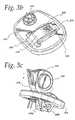
- FIG. 3Bis a perspective view of a faceplate of a hearing instrument showing a protection strip covering a closed battery access door.
- FIG. 3Cis a perspective view of the faceplate shown in FIG. 3B showing a position of the protection strip when the battery access door is opened.
- FIG. 4is a perspective cutaway view of a hearing aid having a toggle switch as a movable structure.
- FIG. 5is a block diagram of a wireless system according to a specific aspect of the present invention.
- FIG. 6is a flow chart diagram of methods of assembling a hearing instrument according to specific aspects of the present invention.
- FIG. 1Ais a cutaway perspective view of a silicon-based transducer assembly 20 which generally includes a transducer chip 24 coplanar with an integrated circuit (IC) chip 26 , an intermediate chip 28 disposed adjacent the transducer chip 24 and the IC chip 26 .
- the transducer chip 24includes a diaphragm 32 and backplate 34 , which may be placed on either side of the diaphragm 32 .
- a seal ring 36surrounds the diaphragm 32 and backplate 34 to form a backchamber 38 . Redistribution circuits on the intermediate chip 28 electrically connect the diaphragm 32 and backplate 34 to the IC chip 26 .
- Pads 42 or solder bumpsare disposed on an exposed surface of the intermediate chip 28 as shown for connection to external components such as a battery (not shown), an amplifier (not shown) or DSP (not shown), a wireless interface (not shown) or a receiver (not shown).
- the pads 42are connected to the transducer chip and/or the ASIC via feedthroughs running through the feedthrough opening 40 . Feedthrough connections can also be made through several feedthrough openings or through closed electrical feedthroughs.
- the transducer chip 24 , the IC chip 26 , and the intermediate chip 28are silicon-based, i.e., include silicon in their composition.
- the transducer assembly 20is fabricated according to microelectromechanical system (MEMS) technology and optionally includes CMOS structures. As is known, a plurality of transducer assemblies may be batch processed on a single wafer. Their structure and fabrication are well known to those skilled in the art.
- MEMSmicroelectromechanical system
- FIG. 1Billustrates a cutaway perspective view of a silicon-based transducer assembly 52 in a stacked arrangement.
- the transducer assembly 52generally includes an intermediate chip 57 and a transducer chip 54 and an IC chip 56 flip-mounted to the intermediate chip 57 preferably using a fluxless soldering technique.
- An opening in the transducer chip 54is covered by a movable diaphragm 60 and a backplate 62 which together form a capacitor whose capacitance varies as the diaphragm is moved in response to incident sound.
- the changes in capacitanceare provided to the IC chip 56 via a feedthrough conductors 63 .
- the feedthrough conductors 63are coupled to the diaphragm 60 and backplate 62 by solder bumps 64 and to the IC chip 56 by interconnects 66 , which could also be solder bumps.
- a seal ring 68surrounds the diaphragm 60 and backplate 62 . Additional details of the transducer assembly 52 shown in FIG. 1B are described and shown in U.S. Pat. No. 6,088,463, titled “Solid State Silicon-Based Condenser Microphone,” issued Jul. 11, 2000, which is incorporated herein by reference in its entirety. It should be noted that the transducer assemblies shown in FIGS. 1A and 1B are exemplary, and that any other suitable silicon-based transducer assembly may be employed.
- Silicon-based transducerscan be batch processed on a single wafer in large quantities, and accordingly, each transducer is highly matched with the other transducers on the same wafer and even on different wafers. As a result, the silicon-based transducers remain stable over long periods of time and are relatively immune to undesired effects of temperature and humidity. These characteristics of silicon-based transducers make them attractive candidates for use in an array, such as a matched pair, and their relatively small size eliminates the space constraint challenges posed by the larger-sized legacy ECMs.
- FIG. 1Cillustrates four silicon-based transducer assemblies 80 a , 80 b , 80 c , 80 d arrayed (i.e., arranged in predetermined manner) on a printed circuit board 82 . Alternately, they may be arrayed on a flex-print.
- Each of the transducer assembliesmay be the transducer assembly 20 shown in FIG. 1A or the transducer assembly 52 shown in FIG. 1B or any other suitable silicon-based transducer assembly.
- each of the transducer assemblies 80 a - dare fabricated from the same wafer to minimize variations in uniformity among transducer assemblies, however, the transducer assemblies 80 a - d may be fabricated from different wafers. Note that the traces shown on the printed circuit board 82 are for illustrative purposes only, and are not meant to show actual placement of the traces.
- the array of transducer assemblies 80can be adapted to provide beam forming or adaptive beam steering according to conventionally known techniques.
- the array of silicon-based transducer assemblies 80can be adapted to achieve directionality, particularly at high frequencies (such as above 4 kHz).
- Directionalitycan be achieved through beam forming using a matched-pair microphone or a microphone array.
- the silicon-based microphones described in connection with FIGS. 1A and 1Bare well suited for matched-pair or array applications because they can be uniformly and reliably batch produced on a single wafer thereby reducing variations in sensitivity and phase responses from one microphone to another.
- matched pair microphones or microphone arrayscan be fabricated as a single assembly on a silicon wafer using MEMS-based fabrication techniques and including a shared IC chip.
- two silicon-based transducer assemblieseach having an output are provided on a substrate, and one output is time delayed and inverted to produce a delayed signal.
- the delayed signalis summed with the other output to produce a summed signal which is provided to processing circuitry for processing the summed signal.
- more than two silicon-based transducer assembliesare employed to achieve directionality.
- signal-to-noise ratiocan be increased by combining the outputs of multiple microphones.
- the relatively miniature size of silicon-based transducers and batch processing capabilitiesrelieve those design challenges, and therefore higher signal-to-noise ratios, are more easily achieved by combining the outputs of multiple transducer assemblies.
- the IC chip 26 or the IC chip 56 described in connection with FIGS. 1A and 1B , respectively,is an application specific integrated circuit (ASIC).
- the ASICpreferably includes CMOS structures.
- the ASICincludes any combination of one or more of the following conventionally known circuit components: an analog-to-digital converter, a digital-to-analog converter, a digital signal processor (DSP), a microprocessor, a preamplifier, a Class-D amplifier, a voltage stabilizer, a charge pump, an impedance correction circuit, an oscillator, a filter such as a low-frequency roll-off filter, an oscillator, and a wireless interface.
- DSPdigital signal processor
- the wireless interfaceincludes a receiver and a transmitter for receiving and transmitting wireless signals, respectively, and optionally includes a modem.
- the Class-D amplifiermay be a pulse width modulated (PWM) or pulse density modulated (PDM) amplifier.
- the transducer assemblies of FIGS. 1A and 1Bmay include one or several sensors and/or actuators. Such sensor may be adapted to detect any combination of temperature, humidity, acceleration, rotation, tilt, pressure, finger touch, or movement. The output of the sensor is provided to compensation circuitry adapted to compensate for changes in the ambient.
- An actuatormay include a receiver (speaker) or a switch.
- a high-frequency roll-off filteris achieved by placing a capacitor (not shown) over the appropriate pads 42 corresponding to the outputs of the transducer chip 24 or 54 .
- the capacitormay be integrated into the intermediate chip 28 or 57 or into the IC chip 26 or 56 .
- arrayto describe the arrangement of silicon-based transducer assemblies is not intended to convey that the assemblies must be arranged in rows and columns. For example, an odd number of assemblies may be arranged in a predetermined fashion on the printed circuit board 82 .
- the array of silicon-based transducer assemblies 80may be connected in parallel via a 3- or 4-wire low-voltage, low-power system bus, such as the system bus described in commonly owned, U.S. Patent Application No. 60/416,952, titled “Digital System Bus For Use in Low Power Instruments Such As Hearing Aids And Listening Devices,” which is incorporated herein by reference in its entirety.
- An appropriate interfaceis integrated into the silicon-based transducer assembly for proper application of the system bus.
- the hearing instrument 200generally includes a housing 202 , a faceplate 204 , a manually movable access door 206 , and a retrieval line 208 .
- the faceplate 204has an opening 210 shaped to receive the access door 206 .
- the access door 206is hingedly connected to the housing 202 when a clip portion 212 of the access door 206 is mated with a pin 214 as shown in FIG. 2B .
- the retrieval line 208can be grasped by the wearer of the hearing instrument 200 to facilitate removal thereof from the ear canal.
- the access door 206provides access to a battery (not shown).
- FIG. 2Bis a cross-sectional view of the hearing instrument 200 showing the placement of a silicon-based transducer assembly 220 installed in the access door 206 .
- the silicon-based transducer assembly 220may be the transducer assembly 20 shown in FIG. 1A , the transducer assembly 52 shown in FIG. 1B , or the array of transducer assemblies 80 shown in FIG. 1C .
- the aperture 216 in the access door 206permits access of sound to the transducer assembly 220 .
- aperturesare formed in the access door 206 to permit access of sound to each of the transducer assemblies.
- the transducer assembly 220may optionally be coupled to a printed circuit board or flex-print. Connections to a power supply, such as a battery, from the transducer assembly 220 are made by conventional techniques known to those skilled in the art. Such connections may be realized, for example, by using pads, wires, traces, solder bumps, or a combination thereof.
- FIG. 2Cshows a hearing instrument 250 having a housing 252 and a manually movable access door 254 disposed adjacent an opening 256 in a faceplate 258 and hingedly connected thereto by pins 260 , 262 .
- the faceplate 258is attached to the housing 252 or may be integrally formed as part of the housing 252 .
- a silicon-based transducer assembly 264is disposed in the access door 254 as shown in FIG. 2D and is manually movable with the access door 254 .
- the silicon-based transducer assembly 264may be the transducer assembly 20 shown in FIG. 1A , the transducer assembly 52 shown in FIG. 1B , or the array of transducer assemblies 80 shown in FIG. 1C .
- the transducer assembly 264may optionally be coupled to a printed circuit board or flex-print. Connections to a power supply, such as a battery 257 , from the transducer assembly 264 are made by conventional techniques known to those skilled in the art.
- FIG. 2Eis a partial cutaway perspective view of a hearing instrument 230 according to another embodiment of the present invention.
- the hearing instrument 230 agenerally includes a housing 232 a , a faceplate 234 a , a battery access door 236 a , a silicon-based transducer assembly 238 a , and a receiver (speaker) 240 a .
- the battery access door 236 ais shown as transparent and partially ajar for ease of illustration, and is manually movable between an open and closed position.
- the silicon-based transducer assembly 238 ais mounted on a flexprint 242 a which electrically couples the transducer assembly 238 a to a control 244 a , a battery 246 a , and the receiver 240 a .
- the battery 246 ais also shown as transparent for ease of illustration. Note that the transducer assembly 238 a is movable with the access door 236 a .
- the access door 236 ais hingedly connected to the faceplate 234 a to facilitate installation and removal of the battery 246 a .
- the control 244 ais a push button, though in other embodiments, it may be a volume dial, a toggle switch, a touch pad, or the like for adjusting hearing instrument parameters such as volume, sensitivity, directionality, frequency response, and gain.
- the hearing instrument 230 aalso includes a connector 241 a coupled to the flexprint 242 a .
- the connector 241 ais adapted to receive an externally provided programming strip 243 a which is composed of a flexprint or substrate that carries a plurality of terminals 245 a .
- the number of terminals 245 amay vary from the illustration.
- the programming strip 243 ais used to program any combination of characteristics of the hearing instrument 230 a . These characteristics include sensitivity, frequency response, gain, and directionality.
- the programming strip 243 ais inserted into the connector 241 a .
- Programming instructionsare communicated between a programming unit (not shown) and the hearing instrument 230 a along the flexprint 242 a according to conventionally known techniques.
- the power during programmingmay be supplied by the battery 246 a or the programming unit.
- FIG. 2Fillustrates a hearing instrument 230 b having a different battery access door 236 b according to another embodiment of the present invention.
- the hearing instrument 230 bgenerally includes a housing 232 b , a faceplate 234 b , a battery access door 236 b , a silicon-based transducer assembly 238 b , and a receiver (speaker) 240 b .
- the battery access door 236 bholds a battery 246 b as shown and includes a control 244 b for adjusting parameters of the hearing instrument 230 b .
- the battery access door 236 bis manually movable between an open and closed position.
- a flexprint 242 belectrically couples a silicon-based transducer assembly 238 b to the control 244 b , the battery 246 b , and the receiver 240 b.
- the hearing instrument 230 balso includes a connector 241 b which receives a programming strip 243 b carrying a plurality of terminals 245 b .
- the hearing instrument 230 balso includes a retrieval line 247 b to facilitate insertion and removal of the hearing instrument 230 b relative to the operator's ear canal.
- the retrieval line 247 balso functions as an antenna to communicate wireless data between the hearing instrument 230 b and another system, such as another hearing instrument or a network. The wireless communication is described in further detail with reference to FIG. 5 .
- FIG. 2Gis an illustration of two silicon-based transducer assemblies mounted into a battery door of a hearing instrument 230 c by injection molding techniques.
- the hearing instrument 230 cincludes a two-piece, manually movable access door 236 c composed of a cap 231 c and a support piece 233 c .
- a flexprint 242 cis sandwiched between the cap 231 c and the support piece 233 c , and a first silicon-based transducer assembly 238 c and a second silicon-based transducer assembly 239 c are electrically coupled to the flexprint 242 c .
- the flexprint 242 cdepends into the hearing instrument 230 c to connect a receiver (speaker). Connections to the battery 246 c are made according to conventionally known techniques.
- FIG. 2His identical to FIG. 2G except that only one silicon-based transducer assembly is shown.
- a hearing instrument 230 dincludes a two-piece, manually movable access door 236 d composed of a cap 231 d and a support piece 233 d .
- a flexprint 242 dis sandwiched between the cap 231 d and the support piece 233 d , and a silicon-based transducer assembly 238 d is electrically coupled to the flexprint 242 d .
- the flexprint 242 ddepends into the hearing instrument 230 d to connect a receiver (speaker). Connections to the battery 246 d are made according to conventionally known techniques.
- connection between the faceplate and battery access door shown in FIGS. 2A-2Hmay be modified to provide vibration isolation by forming a suspension between the faceplate and battery access door. Because the combined mass of the battery access door and the battery is relatively high, a reasonably stiff suspension would obtain a relatively low resonance frequency (around a couple of 100 Hz), which improves performance in the 2-3 kHz range.
- the suspensionis preferably formed along the hinge connecting the battery access door to the faceplate and along the portion of faceplate that holds the battery door in a secure position such that the battery access door “sits up” or is suspended from the faceplate so that vibrations are transmitted via the suspension to the access door.
- FIGS. 2A-2HAnother feature of the access doors shown in FIGS. 2A-2H is that they are easily replaced and repaired without having to send the hearing instrument back to the factory. Replacement and/or repair of the hearing instrument can be done by the user.
- the battery access dooris coupled to the faceplate or housing of the hearing instrument by a solderless connection, permitting easy replacement and repair of a damaged component.
- the silicon-based transducerbecomes damaged, the user can order a replacement access door containing a new silicon-based transducer from the factory.
- the factorywould mail a replacement access door with integrated transducer to the user with appropriate instructions.
- a user's hearing instrumentmay also be upgraded, for example, to a hearing instrument capable of achieving directionality.
- FIG. 3shows a manually movable dial 306 which is secured to a housing 304 of a hearing instrument 300 .
- the dial 306includes an aperture 302 and a silicon-based transducer assembly 308 disposed adjacent the aperture 302 in the dial 306 as shown in FIG. 3A .
- the dial 306is movable in a rotational direction to adjust a characteristic of the hearing instrument 300 , such as volume or sensitivity.
- the transducer assembly 308is the transducer assembly 20 shown in FIG. 1A , though in alternate embodiments, the transducer assembly 308 may be the transducer assembly 52 shown in FIG. 1B , or the array of transducer assemblies 80 shown in FIG. 1C . In the latter alternate embodiment that includes an array of transducer assemblies, the dial 302 includes a plurality of apertures positioned and dimensioned to permit access of sound to each of the corresponding transducer assemblies.
- FIGS. 3B and 3Cillustrate different views of a faceplate 310 of a hearing instrument having a protection strip 318 (shown as transparent for ease of illustration) disposed across a battery access door 312 .
- a silicon-based transducer assembly 316is integrated into the battery access door 312 in accordance with any embodiment described above.
- the protection strip 318is secured to the faceplate 310 by a connection 320 using an adhesive, a clamping member, or the like.
- the protection strip 318covers and protects the silicon-based transducer assembly 316 and permits sound access via a grid 322 which is formed in the area that coincides with the sound access area of the silicon-based transducer.
- the protection strip 318is preferably composed of the same material as the faceplate 310 such as plastic (Kapton), or any other suitable material.
- the holes in the grid 322are dimensioned so as to critically damp the microphone to have an acoustic roll-off above 10 kHz to prevent spurious signals above 10 kHz (such as signals from ultrasonic alarm systems, garage door openers, and the like) from adversely affecting the internal electronics of the hearing instrument.
- various parameters of the hearing instrumentcan be programmed by altering the amount, dimensions, and positions of the holes in the grid 322 as well as by altering the thickness of the protection strip 318 . Accordingly, the protection strip 318 can be easily replaced with another by de-attaching the protection strip 318 from its connection 320 . Additional parameters may be adjusted via a control dial 314 mounted to the faceplate 310 .
- the grid 322 of the protection strip 318is extended beyond the battery access door 312 in the direction of arrow A.
- the extended portion of the protection strip 318can then be peeled away from the battery access door 312 to clean the grid 322 of any debris that may have accumulated in the holes of the grid 322 .
- the ability to clean the grid 322is particularly useful for wearers of hearing aids who also use hairspray or work in dusty environments.
- the protection strip 318can be simply be replaced instead of cleaned by detaching the protection strip 318 from the connection 320 as described earlier and reattaching a replacement strip. After cleaning the grid 322 of the protection strip 318 , the battery access door 312 is closed, and power to the internal circuitry of the hearing instrument is restored via terminals 326 a,b.
- the movable structureis a switch 402 , which is secured to a housing 404 of a hearing instrument 400 .
- the switch 402includes a base portion 405 and a protruding portion 406 .
- a silicon-based transducer assembly 408is disposed in the protruding portion 406 of the switch 402 .
- An aperture 410is formed at the exposed end of the protruding portion 406 to permit access of sound to the transducer assembly 408 as shown.
- the transducer assembly 408is the transducer assembly 20 shown in FIG. 1A , though in alternate embodiments, the transducer assembly 408 may be the transducer assembly 52 shown in FIG. 1B , or the array of transducer assemblies 80 shown in FIG. 1C .
- the transducer assembly 408is shown in the protruding portion 406 of the switch 402 , the protruding portion 406 could be replaced by the transducer assembly 408 and an optional substrate so that the transducer assembly 408 forms a protruding portion.
- the switch 402may be of the toggle, rotary, or pushbutton type.
- the transducer assembly 408may be disposed in any position in the protruding portion or may itself form the protruding portion.
- the transducer assemblymay be disposed in the depressable portion of the pushbutton or may itself form the depressable portion.
- the movable structureis a touch pad disposed over an opening or cavity in a housing of a hearing instrument.
- a silicon-based transducer assemblysuch as the transducer assembly 20 shown in FIG. 1A , is disposed adjacent the touch pad which includes an aperture to permit access of sound to the transducer assembly.
- a touch padtypically includes two transparent films separated by a nonconducting material to maintain a distance between the two films. When the two films are pressed together, driver circuitry and associated software detect the location of touch and perform a programmed function. In this manner, the touch pad operates as a switch, and may be programmed to perform a certain function when the touch pad is touched.
- the functionmay be turning the hearing instrument on or off, switching the hearing instrument to a telecoil mode, switching to wireless mode as described in connection with FIG. 5 , switching to a different acoustic environment mode, changing directionality profiles, or regulating the volume.
- the driver circuitry and softwarecan detect direction.
- the direction of movementis interpreted by software and a function is performed, such as lowering or raising volume, raising or lowering sensitivity.
- the touch pad embodimentmay be adapted for use in a Behind-The-Ear hearing instrument, though it is also suitable for use in a hearing instrument of the Completely-In-Canal, In-the-Canal, or In-The-Ear type.
- the hearing instruments 200 , 250 , 300 , 400 shown in FIGS. 2A to 4are hearing aids of the Completely-In-Canal type, although in alternate embodiments, they may be of the In-the-Canal, In-the-Ear, or Behind-the-Ear type.
- a faceplateis shown in the hearing instruments illustrated in FIGS. 2A to 4 , it is understood that in other embodiments, the faceplate may be eliminated and the movable structure disposed in an opening or cavity in the housing of the hearing instrument without departing from the scope of the present invention.
- the shell and manually movable structures shown in FIGS. 2A to 4are made by conventional SLA (stereolithography) techniques.
- the manually movable structuree.g., battery access door
- stereolithography techniquesleaving an opening for a modules containing the working elements of the hearing instrument. This approach simplifies the manufacturing process, and avoids using multiple techniques to form the housing of the hearing instrument.
- the shape of the manually movable structureis customized using stereolithography techniques to optimize the placement of the silicon-based transducer(s) for each individual wearer. Because the silicon-based transducer is coupled to the manually movable structure, the shape of the manually movable structure (such as more or less convex), the position and number of the silicon-based transducers, and ridges and other deformations on the manually movable structure can be adjusted or formed to compensate for diffraction and ear and head geometry of each individual wearer and to make directionality possible for hearing instruments.
- the conductive wires to connect the silicon-based transducer to other working components of the hearing instrumentmay also be integrated by using stereolithography. Because the wires are in place before assembly, the silicon-based transducers can be easily inserted and replaced. It should be noted that the conductive wires may be made of conductive rubber.
- any of the transducer assemblies shown and described in connection with the foregoingmay operate as a switch by detecting transients in air pressure induced by touching the sound inlet of the transducer assembly. Because the transients in pressure would be higher than typical sound pressures, they can be detected by detecting an overload or collapse of the membrane.
- the hearing instruments described abovemay be adapted to be disposable. Disposable hearing instruments should be relatively inexpensive to increase their attractiveness. Lower costs may be achieved by reducing the functional components in the ASIC, fixing the battery in the housing without providing an access door, using cheaper materials, or using silicon-based microphones that do not entirely meet quality control standards but are still functional.
- the teachings of the present inventionextend to other devices besides hearing instruments such as hearing aids.
- the present inventioncontemplates any device capable of transducing between acoustic signals and corresponding electrical signals, such as an earphone, a headphone, or a headset, for example. Any of the embodiments described herein may be incorporated into any such device.
- a silicon-based transducermay be a silicon-based microphone or a silicon-based receiver (speaker), depending upon the application.
- FIG. 5illustrates a block diagram of a wireless system 700 that generally includes a hearing instrument 702 a , an optional hearing instrument 702 b , and a network 704 .
- the hearing instruments 702 a,bmay be any of the hearing instruments described above, and include a silicon-based transducer assembly 706 a,b , an ASIC 708 a,b , and a wireless interface 710 a,b , respectively.
- the silicon-based transducer assemblies 706 a,bmay be any of the transducer assemblies described in connection with FIGS. 1A to 1C . In another embodiment, the silicon-based transducer assemblies 706 a,b are silicon-based receivers.
- the wireless interfaces 710 a,bare coupled to antennas 712 a,b , respectively.
- the network 704is coupled to an antenna 714 .
- the wireless interfaces 710 a,bare short-range RF links.
- the wireless interfaces 710 a,balso include conventional transceivers and modems for enabling wireless communication.
- wireless communicationmay be established between the hearing instruments 702 a , 702 b and the network 704 or between the hearing instrument 702 a and the hearing instrument 702 b to communicate wireless data therebetween.
- the wireless datamay be modulated according to any conventionally known modulation technique, and may be transmitted or received on carriers in any suitable frequency range, such as Bluetooth, 802.11, cellular, RF, and so forth.
- the network 704communicates wireless data to the hearing instrument 702 a in the form of modulated audio signals.
- the network 704broadcasts specific audio data over the wireless spectrum to hearing instruments which are adapted for wireless communications. In this manner, for example, a hearing impaired person sitting in the back of a large conference room may comfortably hear a distant speaker, or an undercover agent may discretely receive instructions from a remote operator without compromising his cover.
- the network 704communicates wireless data to the hearing instrument 702 a in the form of programming instructions.
- the programming instructionscontain data which adjusts characteristics of the hearing instrument 702 a .
- the characteristicsinclude sensitivity, gain, frequency response, and, directionality.
- the programmingmay occur as the hearing instrument 702 a is worn by its operator, thus allowing the operator to hear the effects immediately.
- the programming instructionsmay also be used to program a different function associated with a movable structure on the hearing instrument.
- the movable structureis a rotatable dial, such as described in connection with FIGS. 3 and 3A , and adapted to change the volume of a receiver
- the programming instructionsmay program the function of the rotatable dial to change sensitivity or other characteristic of the hearing instrument.
- the movable structureis a toggle switch, such as described in connection with FIG. 4
- the function(s) associated with the toggle switchmay be altered using the programming instructions.
- the hearing instrument 702 acommunicates wireless data between the hearing instrument 702 b .
- this embodimentallows two hearing instruments worn by an operator to communicate audio signals for improved directional or truly three-dimensional hearing.
- the hearing instrument 702 ais programmed through ultrasound.
- the silicon-based transduceris sensitive up to 100 kHz, which allows the hearing instrument 702 a to be programmed without additional cables, flex strips, RF devices, etc.
- the silicon-based transducer assemblyincludes a digital filter to extract wireless data including audio data and programming information carried over ultrasound frequencies. Ultrasound transmission is improved by mounting the silicon-based transducer assembly in a manner described herein.
- FIG. 6is a flow chart of a method of assembling a hearing instrument according to the present invention. It should be noted that although the steps are shown in FIG. 6 in a particular order, the steps may be performed in any order without departing from the scope of the present invention.
- a housingis provided.
- a faceplate having an openingis attached to the housing at step 802 .
- a moveable structureis secured adjacent the opening at step 804 , and at step 806 , a silicon-based transducer assembly is coupled to the moveable structure.
- a silicon-based transducer assemblyis mounted to a substrate at step 808 , and the substrate is attached as a moveable structure to the housing at step 810 .
- the housing, faceplate, moveable structure, and silicon-based transducer assemblyare described in further detail in connection with FIGS. 1A to 5 and may be used in various embodiments in accordance with the method shown in FIG. 6 .
Landscapes
- Physics & Mathematics (AREA)
- Engineering & Computer Science (AREA)
- Acoustics & Sound (AREA)
- Signal Processing (AREA)
- Health & Medical Sciences (AREA)
- General Health & Medical Sciences (AREA)
- Neurosurgery (AREA)
- Otolaryngology (AREA)
- Electrostatic, Electromagnetic, Magneto- Strictive, And Variable-Resistance Transducers (AREA)
- Circuit For Audible Band Transducer (AREA)
- Light Receiving Elements (AREA)
Abstract
Description
Claims (20)
Priority Applications (1)
| Application Number | Priority Date | Filing Date | Title |
|---|---|---|---|
| US11/605,095US7792315B2 (en) | 2002-12-20 | 2006-11-28 | Silicon-based transducer for use in hearing instruments and listening devices |
Applications Claiming Priority (2)
| Application Number | Priority Date | Filing Date | Title |
|---|---|---|---|
| US10/326,208US7142682B2 (en) | 2002-12-20 | 2002-12-20 | Silicon-based transducer for use in hearing instruments and listening devices |
| US11/605,095US7792315B2 (en) | 2002-12-20 | 2006-11-28 | Silicon-based transducer for use in hearing instruments and listening devices |
Related Parent Applications (1)
| Application Number | Title | Priority Date | Filing Date |
|---|---|---|---|
| US10/326,208ContinuationUS7142682B2 (en) | 2002-12-20 | 2002-12-20 | Silicon-based transducer for use in hearing instruments and listening devices |
Publications (2)
| Publication Number | Publication Date |
|---|---|
| US20070071260A1 US20070071260A1 (en) | 2007-03-29 |
| US7792315B2true US7792315B2 (en) | 2010-09-07 |
Family
ID=32593962
Family Applications (2)
| Application Number | Title | Priority Date | Filing Date |
|---|---|---|---|
| US10/326,208Expired - LifetimeUS7142682B2 (en) | 2002-12-20 | 2002-12-20 | Silicon-based transducer for use in hearing instruments and listening devices |
| US11/605,095Expired - LifetimeUS7792315B2 (en) | 2002-12-20 | 2006-11-28 | Silicon-based transducer for use in hearing instruments and listening devices |
Family Applications Before (1)
| Application Number | Title | Priority Date | Filing Date |
|---|---|---|---|
| US10/326,208Expired - LifetimeUS7142682B2 (en) | 2002-12-20 | 2002-12-20 | Silicon-based transducer for use in hearing instruments and listening devices |
Country Status (7)
| Country | Link |
|---|---|
| US (2) | US7142682B2 (en) |
| EP (1) | EP1574112B1 (en) |
| AT (1) | ATE381239T1 (en) |
| AU (1) | AU2003290452A1 (en) |
| DE (1) | DE60318107T2 (en) |
| DK (1) | DK1574112T3 (en) |
| WO (1) | WO2004057909A2 (en) |
Cited By (8)
| Publication number | Priority date | Publication date | Assignee | Title |
|---|---|---|---|---|
| US20070047746A1 (en)* | 2005-08-23 | 2007-03-01 | Analog Devices, Inc. | Multi-Microphone System |
| US20090067659A1 (en)* | 2007-09-12 | 2009-03-12 | Christian Wang | Miniature microphone assembly with hydrophobic surface coating |
| US20090123014A1 (en)* | 2007-11-09 | 2009-05-14 | Siemens Medical Instruments Pte. Ltd. | In-the-ear hearing device housing and the production thereof |
| US20110006381A1 (en)* | 2007-12-07 | 2011-01-13 | Epcos Ag | Mems package and method for the production thereof |
| US9056760B2 (en) | 2010-01-29 | 2015-06-16 | Epcos Ag | Miniaturized electrical component comprising an MEMS and an ASIC and production method |
| US9648429B2 (en) | 2013-05-10 | 2017-05-09 | Starkey Laboratories, Inc. | Hearing assistance device with improved microphone protection |
| US10835931B2 (en) | 2017-10-17 | 2020-11-17 | Eargo, Inc. | Device-cleaning wax guards |
| US11140498B2 (en) | 2017-10-17 | 2021-10-05 | Eargo, Inc. | Wax management system |
Families Citing this family (157)
| Publication number | Priority date | Publication date | Assignee | Title |
|---|---|---|---|---|
| US7434305B2 (en) | 2000-11-28 | 2008-10-14 | Knowles Electronics, Llc. | Method of manufacturing a microphone |
| US8623710B1 (en) | 2000-11-28 | 2014-01-07 | Knowles Electronics, Llc | Methods of manufacture of bottom port multi-part surface mount silicon condenser microphone packages |
| EP1570464A4 (en) | 2002-12-11 | 2006-01-18 | Softmax Inc | System and method for speech processing using independent component analysis under stability constraints |
| DE10260303B3 (en)* | 2002-12-20 | 2004-06-17 | Siemens Audiologische Technik Gmbh | Microphone module for hearing aid, has several microphones attached to common carrier and electrically connected via 3-dimensional conductor paths |
| US7142682B2 (en)* | 2002-12-20 | 2006-11-28 | Sonion Mems A/S | Silicon-based transducer for use in hearing instruments and listening devices |
| JP4196089B2 (en)* | 2003-08-29 | 2008-12-17 | パナソニック株式会社 | Speaker device |
| US7099821B2 (en)* | 2003-09-12 | 2006-08-29 | Softmax, Inc. | Separation of target acoustic signals in a multi-transducer arrangement |
| DE10343292B3 (en)* | 2003-09-18 | 2004-12-02 | Siemens Audiologische Technik Gmbh | Hearing aid e.g. for hearing impaired people, without separate microphone housing, has hearing aid housing and a microphone housing which are formed from a one-piece with housing having cover for acoustic isolation |
| US20050074543A1 (en)* | 2003-10-07 | 2005-04-07 | Stevens Randal A. | Method of coating an SLA part |
| EP1690332A1 (en)* | 2003-12-01 | 2006-08-16 | Audioasics A/S | Microphone with voltage pump |
| US7929714B2 (en)* | 2004-08-11 | 2011-04-19 | Qualcomm Incorporated | Integrated audio codec with silicon audio transducer |
| US20060067544A1 (en)* | 2004-09-29 | 2006-03-30 | Knowles Electronics, Llc | Method and apparatus for powering a listening device |
| US7508949B2 (en)* | 2004-10-12 | 2009-03-24 | In'tech Industries, Inc. | Face plate connector for hearing aid |
| US20100020994A1 (en)* | 2004-10-28 | 2010-01-28 | Christensen Craig L | Antenna integrated with retrieval component of hearing aid |
| US7593538B2 (en)* | 2005-03-28 | 2009-09-22 | Starkey Laboratories, Inc. | Antennas for hearing aids |
| US7449356B2 (en)* | 2005-04-25 | 2008-11-11 | Analog Devices, Inc. | Process of forming a microphone using support member |
| US7885423B2 (en) | 2005-04-25 | 2011-02-08 | Analog Devices, Inc. | Support apparatus for microphone diaphragm |
| US7825484B2 (en)* | 2005-04-25 | 2010-11-02 | Analog Devices, Inc. | Micromachined microphone and multisensor and method for producing same |
| DE102005030151B3 (en)* | 2005-06-28 | 2006-11-02 | Fraunhofer-Gesellschaft zur Förderung der angewandten Forschung e.V. | Photo-acoustic free-field detector for measuring air, gas and liquid flows has optical and acoustic mirrors arranged in position where local maximum sound pressure is present for generating acoustic energy based on output of acoustic sensor |
| US7464029B2 (en)* | 2005-07-22 | 2008-12-09 | Qualcomm Incorporated | Robust separation of speech signals in a noisy environment |
| DE102006001886A1 (en)* | 2006-01-13 | 2007-07-19 | Siemens Audiologische Technik Gmbh | Microphone device with multiple silicon microphones for a hearing device |
| GB2435544B (en)* | 2006-02-24 | 2008-11-19 | Oligon Ltd | Mems device |
| WO2007103037A2 (en)* | 2006-03-01 | 2007-09-13 | Softmax, Inc. | System and method for generating a separated signal |
| EP2044802B1 (en)* | 2006-07-25 | 2013-03-27 | Analog Devices, Inc. | Multiple microphone system |
| TWI319690B (en)* | 2006-09-08 | 2010-01-11 | Ind Tech Res Inst | Structure and manufacturing method of inversed microphone module and microphone chip component |
| US20080175425A1 (en)* | 2006-11-30 | 2008-07-24 | Analog Devices, Inc. | Microphone System with Silicon Microphone Secured to Package Lid |
| CN101287304B (en) | 2006-12-18 | 2013-02-06 | 桑尼奥公司 | Deep Submicron MOS Preamplifier with Thick Oxide Input Stage Transistors |
| US8494195B2 (en)* | 2007-02-07 | 2013-07-23 | Starkey Laboratories, Inc. | Electrical contacts using conductive silicone in hearing assistance devices |
| US20080192962A1 (en) | 2007-02-13 | 2008-08-14 | Sonion Nederland B.V. | Microphone with dual transducers |
| EP2115743A1 (en)* | 2007-02-26 | 2009-11-11 | QUALCOMM Incorporated | Systems, methods, and apparatus for signal separation |
| US8160273B2 (en)* | 2007-02-26 | 2012-04-17 | Erik Visser | Systems, methods, and apparatus for signal separation using data driven techniques |
| EP2132955A1 (en)* | 2007-03-05 | 2009-12-16 | Gtronix, Inc. | Small-footprint microphone module with signal processing functionality |
| US20090000630A1 (en)* | 2007-03-05 | 2009-01-01 | Ricardo Alfredo Fuenmayor Aray | Instant Face-Lifter |
| US20080230495A1 (en)* | 2007-03-19 | 2008-09-25 | Siemens Hearing Instruments Inc. | Secure Mount For A Hearing Instrument Electronics Module |
| US8180084B2 (en)* | 2007-03-21 | 2012-05-15 | Starkey Laboratories, Inc. | Integrated battery door and switch |
| US8135163B2 (en)* | 2007-08-30 | 2012-03-13 | Klipsch Group, Inc. | Balanced armature with acoustic low pass filter |
| DE102007042324B4 (en)* | 2007-09-06 | 2012-08-30 | Siemens Medical Instruments Pte. Ltd. | In-the-ear hearing aid with contact means and associated battery charger |
| EP2040490B2 (en)† | 2007-09-18 | 2021-02-24 | Starkey Laboratories, Inc. | Method and apparatus for a hearing assistance device using mems sensors |
| US8385573B2 (en)* | 2007-09-19 | 2013-02-26 | Starkey Laboratories, Inc. | System for hearing assistance device including receiver in the canal |
| US8175291B2 (en)* | 2007-12-19 | 2012-05-08 | Qualcomm Incorporated | Systems, methods, and apparatus for multi-microphone based speech enhancement |
| DE102007061591B4 (en)* | 2007-12-20 | 2009-10-29 | Siemens Medical Instruments Pte. Ltd. | Energy storage device holding device with covered charging contacts, housing module and associated hearing aid |
| US8321214B2 (en)* | 2008-06-02 | 2012-11-27 | Qualcomm Incorporated | Systems, methods, and apparatus for multichannel signal amplitude balancing |
| US7760144B2 (en)* | 2008-08-04 | 2010-07-20 | Taiwan Semiconductor Manufacturing Company, Ltd. | Antennas integrated in semiconductor chips |
| CA2639555A1 (en)* | 2008-08-11 | 2008-12-15 | Hyman Ngo | High definition litho applique and emblems |
| US8781141B2 (en) | 2008-08-27 | 2014-07-15 | Starkey Laboratories, Inc. | Modular connection assembly for a hearing assistance device |
| US8737658B2 (en) | 2008-12-19 | 2014-05-27 | Starkey Laboratories, Inc. | Three dimensional substrate for hearing assistance devices |
| US8565457B2 (en) | 2008-12-19 | 2013-10-22 | Starkey Laboratories, Inc. | Antennas for standard fit hearing assistance devices |
| US8699733B2 (en)* | 2008-12-19 | 2014-04-15 | Starkey Laboratories, Inc. | Parallel antennas for standard fit hearing assistance devices |
| US8494197B2 (en)* | 2008-12-19 | 2013-07-23 | Starkey Laboratories, Inc. | Antennas for custom fit hearing assistance devices |
| US10142747B2 (en) | 2008-12-19 | 2018-11-27 | Starkey Laboratories, Inc. | Three dimensional substrate for hearing assistance devices |
| IT1395550B1 (en) | 2008-12-23 | 2012-09-28 | St Microelectronics Rousset | INTEGRATED ACOUSTIC TRANSDUCER IN MEMS TECHNOLOGY AND RELATIVE PROCESS OF PROCESSING |
| US8879763B2 (en) | 2008-12-31 | 2014-11-04 | Starkey Laboratories, Inc. | Method and apparatus for detecting user activities from within a hearing assistance device using a vibration sensor |
| US9473859B2 (en) | 2008-12-31 | 2016-10-18 | Starkey Laboratories, Inc. | Systems and methods of telecommunication for bilateral hearing instruments |
| US8798299B1 (en) | 2008-12-31 | 2014-08-05 | Starkey Laboratories, Inc. | Magnetic shielding for communication device applications |
| EP2254353B1 (en)* | 2009-05-19 | 2017-07-05 | Sivantos Pte. Ltd. | Hearing device with a sound transducer and method for manufacturing a sound transducer |
| US8571249B2 (en)* | 2009-05-29 | 2013-10-29 | General Mems Corporation | Silicon microphone package |
| KR20130137050A (en)* | 2009-06-29 | 2013-12-13 | 노키아 코포레이션 | Temperature compensated microphone |
| EP2285136B1 (en) | 2009-07-15 | 2015-10-14 | Siemens Medical Instruments Pte. Ltd. | Hearing aid with replaceable earpiece |
| DK2278828T3 (en)* | 2009-07-23 | 2017-11-27 | Starkey Labs Inc | METHOD AND APPARATUS FOR AN ISOLATED ELECTROMAGNETIC SCREEN FOR USE IN HEARING DEVICES |
| KR101612851B1 (en)* | 2010-02-01 | 2016-04-18 | 삼성전자주식회사 | Small hearing aid |
| US8638965B2 (en)* | 2010-07-14 | 2014-01-28 | Starkey Laboratories, Inc. | Receiver-in-canal hearing device cable connections |
| DE102010039303A1 (en)* | 2010-08-13 | 2012-02-16 | Siemens Medical Instruments Pte. Ltd. | Method for reducing interference and hearing device |
| US9049526B2 (en) | 2011-03-19 | 2015-06-02 | Starkey Laboratories, Inc. | Compact programming block connector for hearing assistance devices |
| GB201107007D0 (en)* | 2011-04-27 | 2011-06-08 | Soundchip Sa | Earphone apparatus |
| US9232302B2 (en)* | 2011-05-31 | 2016-01-05 | Apple Inc. | Microphone assemblies with through-silicon vias |
| US20130028459A1 (en)* | 2011-07-28 | 2013-01-31 | Yunlong Wang | Monolithic Silicon Microphone |
| WO2013004623A1 (en) | 2011-07-07 | 2013-01-10 | Sonion Nederland Bv | A multiple receiver assembly and a method for assembly thereof |
| US9374643B2 (en) | 2011-11-04 | 2016-06-21 | Knowles Electronics, Llc | Embedded dielectric as a barrier in an acoustic device and method of manufacture |
| EP2781107B1 (en) | 2011-11-17 | 2016-11-23 | InvenSense, Inc. | Microphone module with sound pipe |
| US9386384B2 (en)* | 2012-01-03 | 2016-07-05 | Starkey Laboratories, Inc. | Hearing instrument transduction apparatus using ferroelectret polymer foam |
| US9191761B2 (en)* | 2012-01-30 | 2015-11-17 | Etymotic Research, Inc. | Hearing testing probe with integrated temperature and humidity sensors and active temperature control |
| EP2832111B1 (en) | 2012-03-26 | 2018-05-23 | University of Surrey | Acoustic source separation |
| US9078063B2 (en) | 2012-08-10 | 2015-07-07 | Knowles Electronics, Llc | Microphone assembly with barrier to prevent contaminant infiltration |
| EP2723098B1 (en) | 2012-10-18 | 2016-12-14 | Sonion Nederland B.V. | A dual transducer with shared diaphragm |
| US9247359B2 (en) | 2012-10-18 | 2016-01-26 | Sonion Nederland Bv | Transducer, a hearing aid comprising the transducer and a method of operating the transducer |
| DK2747459T3 (en) | 2012-12-21 | 2018-12-17 | Sonion Nederland Bv | RIC unit with Thuras tube |
| EP2750413B1 (en) | 2012-12-28 | 2017-02-22 | Sonion Nederland B.V. | Hearing aid device |
| US9401575B2 (en) | 2013-05-29 | 2016-07-26 | Sonion Nederland Bv | Method of assembling a transducer assembly |
| US20160165367A1 (en)* | 2013-07-22 | 2016-06-09 | Sonova Ag | A rechargeable hearing device and a battery charger for charging the hearing device |
| US10125012B2 (en)* | 2013-08-27 | 2018-11-13 | Infineon Technologies Ag | MEMS device |
| DK2849463T3 (en) | 2013-09-16 | 2018-06-25 | Sonion Nederland Bv | Transducer with moisture transporting element |
| US9906879B2 (en) | 2013-11-27 | 2018-02-27 | Starkey Laboratories, Inc. | Solderless module connector for a hearing assistance device assembly |
| US9913052B2 (en)* | 2013-11-27 | 2018-03-06 | Starkey Laboratories, Inc. | Solderless hearing assistance device assembly and method |
| DK3550852T3 (en) | 2014-02-14 | 2021-02-01 | Sonion Nederland Bv | A joiner for a receiver assembly |
| DK2908559T3 (en) | 2014-02-18 | 2017-01-16 | Sonion As | Process for manufacturing devices for hearing aids |
| DK2914018T3 (en) | 2014-02-26 | 2017-01-30 | Sonion Nederland Bv | Speaker, luminaire and method |
| US10425724B2 (en)* | 2014-03-13 | 2019-09-24 | Starkey Laboratories, Inc. | Interposer stack inside a substrate for a hearing assistance device |
| US9432774B2 (en) | 2014-04-02 | 2016-08-30 | Sonion Nederland B.V. | Transducer with a bent armature |
| EP2953380A1 (en) | 2014-06-04 | 2015-12-09 | Sonion Nederland B.V. | Acoustical crosstalk compensation |
| DK3041263T3 (en) | 2014-12-30 | 2022-04-11 | Sonion Nederland Bv | Hybrid receiver module |
| EP3051841B1 (en) | 2015-01-30 | 2020-10-07 | Sonion Nederland B.V. | A receiver having a suspended motor assembly |
| DK3057339T3 (en) | 2015-02-10 | 2021-01-04 | Sonion Nederland Bv | Microphone module with common middle audio input device |
| US9980029B2 (en) | 2015-03-25 | 2018-05-22 | Sonion Nederland B.V. | Receiver-in-canal assembly comprising a diaphragm and a cable connection |
| EP3073764B1 (en) | 2015-03-25 | 2021-04-21 | Sonion Nederland B.V. | A hearing aid comprising an insert member |
| US9565488B2 (en)* | 2015-05-20 | 2017-02-07 | Infineon Technologies Ag | Micro-electro-mechanical system devices |
| US9794661B2 (en) | 2015-08-07 | 2017-10-17 | Knowles Electronics, Llc | Ingress protection for reducing particle infiltration into acoustic chamber of a MEMS microphone package |
| DK3133829T3 (en) | 2015-08-19 | 2020-06-22 | Sonion Nederland Bv | AUDIO UNIT WITH IMPROVED FREQUENCY RESPONSE |
| EP3139627B1 (en) | 2015-09-02 | 2019-02-13 | Sonion Nederland B.V. | Ear phone with multi-way speakers |
| US9668065B2 (en) | 2015-09-18 | 2017-05-30 | Sonion Nederland B.V. | Acoustical module with acoustical filter |
| EP3157270B1 (en) | 2015-10-14 | 2021-03-31 | Sonion Nederland B.V. | Hearing device with vibration sensitive transducer |
| DK3160157T3 (en) | 2015-10-21 | 2018-12-17 | Sonion Nederland Bv | Vibration-compensated vibroacoustic device |
| US10582303B2 (en) | 2015-12-04 | 2020-03-03 | Sonion Nederland B.V. | Balanced armature receiver with bi-stable balanced armature |
| EP3185584B1 (en) | 2015-12-21 | 2020-04-22 | Sonion Nederland B.V. | Receiver assembly having a distinct longitudinal direction |
| DK3197046T3 (en) | 2016-01-25 | 2021-07-05 | Sonion Nederland Bv | Self-biased output booster amplifier as well as its use |
| US10687148B2 (en) | 2016-01-28 | 2020-06-16 | Sonion Nederland B.V. | Assembly comprising an electrostatic sound generator and a transformer |
| EP3232685B1 (en) | 2016-04-13 | 2021-03-03 | Sonion Nederland B.V. | A dome for a personal audio device |
| US10045121B2 (en)* | 2016-04-29 | 2018-08-07 | Invensense, Inc. | Microelectromechanical systems (MEMS) microphone bias voltage |
| EP3252444B1 (en) | 2016-06-01 | 2023-12-20 | Sonion Nederland B.V. | Vibration or acceleration sensor applying squeeze film damping |
| EP3279621B2 (en) | 2016-08-26 | 2025-04-09 | Sonion Nederland B.V. | Vibration sensor with low-frequency roll-off response curve |
| EP3293985B1 (en) | 2016-09-12 | 2021-03-24 | Sonion Nederland B.V. | Receiver with integrated membrane movement detection |
| DK3313097T3 (en) | 2016-10-19 | 2020-10-19 | Sonion Nederland Bv | AN EAR BUD OR DOME |
| US10244301B2 (en)* | 2016-10-27 | 2019-03-26 | Starkey Laboratories, Inc. | Power management shell for ear-worn electronic device |
| US20180145643A1 (en) | 2016-11-18 | 2018-05-24 | Sonion Nederland B.V. | Circuit for providing a high and a low impedance and a system comprising the circuit |
| EP3324649A1 (en) | 2016-11-18 | 2018-05-23 | Sonion Nederland B.V. | A transducer with a high sensitivity |
| EP3324538A1 (en) | 2016-11-18 | 2018-05-23 | Sonion Nederland B.V. | A sensing circuit comprising an amplifying circuit |
| US10327072B2 (en) | 2016-11-18 | 2019-06-18 | Sonion Nederland B.V. | Phase correcting system and a phase correctable transducer system |
| EP3337184B1 (en) | 2016-12-14 | 2020-03-25 | Sonion Nederland B.V. | An armature and a transducer comprising the armature |
| EP3337191B1 (en) | 2016-12-16 | 2021-05-19 | Sonion Nederland B.V. | A receiver assembly |
| US10405085B2 (en) | 2016-12-16 | 2019-09-03 | Sonion Nederland B.V. | Receiver assembly |
| US10699833B2 (en) | 2016-12-28 | 2020-06-30 | Sonion Nederland B.V. | Magnet assembly |
| EP3702322A1 (en) | 2016-12-30 | 2020-09-02 | Sonion Nederland B.V. | Micro-electromechanical transducer |
| US10477308B2 (en) | 2016-12-30 | 2019-11-12 | Sonion Nederland B.V. | Circuit and a receiver comprising the circuit |
| US10732714B2 (en) | 2017-05-08 | 2020-08-04 | Cirrus Logic, Inc. | Integrated haptic system |
| EP3407625B1 (en) | 2017-05-26 | 2021-05-05 | Sonion Nederland B.V. | Receiver with venting opening |
| DK3407626T3 (en) | 2017-05-26 | 2020-07-27 | Sonion Nederland Bv | A receiver assembly comprising an armature and a diaphragm |
| DK3429231T3 (en) | 2017-07-13 | 2023-04-11 | Sonion Nederland Bv | Hearing device including vibration prevention device |
| US10820104B2 (en) | 2017-08-31 | 2020-10-27 | Sonion Nederland B.V. | Diaphragm, a sound generator, a hearing device and a method |
| DK3451688T3 (en) | 2017-09-04 | 2021-06-21 | Sonion Nederland Bv | SOUND GENERATOR, SCREEN AND SPOUT |
| GB201714956D0 (en) | 2017-09-18 | 2017-11-01 | Sonova Ag | Hearing device with adjustable venting |
| CN109672967B (en) | 2017-10-16 | 2021-09-17 | 声扬荷兰有限公司 | Personal hearing device |
| DK3471437T3 (en) | 2017-10-16 | 2021-02-15 | Sonion Nederland Bv | A valve, a transducer comprising a valve, a hearing device and a method |
| CN109672963B (en) | 2017-10-16 | 2021-04-30 | 声扬荷兰有限公司 | Acoustic channel element with valve and transducer with acoustic channel element |
| CN108307282B (en)* | 2017-12-26 | 2020-08-07 | 潍坊歌尔微电子有限公司 | Method for verifying welding quality of MEMS microphone |
| DK3567873T3 (en) | 2018-02-06 | 2021-11-15 | Sonion Nederland Bv | Method for controlling an acoustic valve of a hearing device |
| DK3531720T3 (en) | 2018-02-26 | 2021-11-15 | Sonion Nederland Bv | Arranging a sounder and a microphone |
| DK3531713T3 (en) | 2018-02-26 | 2023-02-06 | Sonion Nederland Bv | Miniature Speaker with Acoustical Mass |
| US10832537B2 (en) | 2018-04-04 | 2020-11-10 | Cirrus Logic, Inc. | Methods and apparatus for outputting a haptic signal to a haptic transducer |
| EP3467457B1 (en) | 2018-04-30 | 2022-07-20 | Sonion Nederland B.V. | Vibration sensor |
| DK3579578T3 (en) | 2018-06-07 | 2022-05-02 | Sonion Nederland Bv | MINIATURE ANNOUNCER |
| US10951169B2 (en) | 2018-07-20 | 2021-03-16 | Sonion Nederland B.V. | Amplifier comprising two parallel coupled amplifier units |
| US11269415B2 (en)* | 2018-08-14 | 2022-03-08 | Cirrus Logic, Inc. | Haptic output systems |
| US11564580B2 (en) | 2018-09-19 | 2023-01-31 | Sonion Nederland B.V. | Housing comprising a sensor |
| GB201817495D0 (en) | 2018-10-26 | 2018-12-12 | Cirrus Logic Int Semiconductor Ltd | A force sensing system and method |
| EP3672277B1 (en) | 2018-12-19 | 2024-04-03 | Sonion Nederland B.V. | Miniature speaker with multiple sound cavities |
| US11190880B2 (en) | 2018-12-28 | 2021-11-30 | Sonion Nederland B.V. | Diaphragm assembly, a transducer, a microphone, and a method of manufacture |
| EP3675522A1 (en) | 2018-12-28 | 2020-07-01 | Sonion Nederland B.V. | Miniature speaker with essentially no acoustical leakage |
| US12176781B2 (en) | 2019-03-29 | 2024-12-24 | Cirrus Logic Inc. | Methods and systems for estimating transducer parameters |
| US12035445B2 (en) | 2019-03-29 | 2024-07-09 | Cirrus Logic Inc. | Resonant tracking of an electromagnetic load |
| DK3726855T3 (en) | 2019-04-15 | 2021-11-15 | Sonion Nederland Bv | A personal hearing device with a vent channel and acoustic separation |
| US10976825B2 (en) | 2019-06-07 | 2021-04-13 | Cirrus Logic, Inc. | Methods and apparatuses for controlling operation of a vibrational output system and/or operation of an input sensor system |
| EP3806494B1 (en) | 2019-10-07 | 2023-12-27 | Sonion Nederland B.V. | Hearing device including an optical sensor |
| US12276687B2 (en) | 2019-12-05 | 2025-04-15 | Cirrus Logic Inc. | Methods and systems for estimating coil impedance of an electromagnetic transducer |
| CN111314830B (en)* | 2019-12-07 | 2021-02-19 | 朝阳聚声泰(信丰)科技有限公司 | MEMS microphone with high signal-to-noise ratio and production method thereof |
| EP3836558B1 (en)* | 2019-12-11 | 2025-04-30 | GN Hearing A/S | A hearing aid for placement in a user´s ear canal |
| US11245989B2 (en)* | 2019-12-11 | 2022-02-08 | Gn Hearing A/S | Hearing aid for placement in a user's ear canal |
| CN112954564A (en) | 2019-12-11 | 2021-06-11 | 大北欧听力公司 | Hearing aid for placement in the ear canal of a user |
| US12244253B2 (en) | 2020-04-16 | 2025-03-04 | Cirrus Logic Inc. | Restricting undesired movement of a haptic actuator |
Citations (42)
| Publication number | Priority date | Publication date | Assignee | Title |
|---|---|---|---|---|
| DE3325961A1 (en) | 1983-07-19 | 1985-01-31 | Dietmar Hohm | Silicon-based capacitive transducers incorporating silicon dioxide electret |
| US4598177A (en) | 1985-01-16 | 1986-07-01 | Sears, Roebuck, & Co. | Hearing aid with self-contained battery compartment and volume control |
| US4712245A (en) | 1985-01-24 | 1987-12-08 | Oticon Electronics A/S | In-the-ear hearing aid with the outer wall formed by rupturing a two-component chamber |
| US4922471A (en) | 1988-03-05 | 1990-05-01 | Sennheiser Electronic Kg | Capacitive sound transducer |
| EP0490486A2 (en) | 1990-12-07 | 1992-06-17 | Wisconsin Alumni Research Foundation | Micromachined differential pressure transducers and method of producing the same |
| US5146435A (en) | 1989-12-04 | 1992-09-08 | The Charles Stark Draper Laboratory, Inc. | Acoustic transducer |
| EP0561566A2 (en) | 1992-03-18 | 1993-09-22 | Knowles Electronics, Inc. | Solid state condenser and microphone |
| WO1993019343A1 (en) | 1992-03-16 | 1993-09-30 | Lynxvale Limited | Micromechanical sensor |
| US5255246A (en) | 1991-09-17 | 1993-10-19 | Siemens Nederland N.V. | Electroacoustic transducer of the electret type |
| WO1994025863A2 (en) | 1993-05-05 | 1994-11-10 | Siemens Aktiengesellschaft | Process for depositing a large-surface layer through a mask and optional closure of said mask |
| WO1994030030A1 (en) | 1993-06-04 | 1994-12-22 | The Regents Of The University Of California | Microfabricated acoustic source and receiver |
| US5452268A (en) | 1994-08-12 | 1995-09-19 | The Charles Stark Draper Laboratory, Inc. | Acoustic transducer with improved low frequency response |
| WO1995034917A1 (en) | 1994-06-10 | 1995-12-21 | The Regents Of The University Of California | Cantilever pressure transducer |
| US5490220A (en) | 1992-03-18 | 1996-02-06 | Knowles Electronics, Inc. | Solid state condenser and microphone devices |
| US5531787A (en) | 1993-01-25 | 1996-07-02 | Lesinski; S. George | Implantable auditory system with micromachined microsensor and microactuator |
| WO1996030182A1 (en) | 1995-03-30 | 1996-10-03 | Crivello James V | Methods and compositions related to stereolithography |
| US5573679A (en) | 1995-06-19 | 1996-11-12 | Alberta Microelectronic Centre | Fabrication of a surface micromachined capacitive microphone using a dry-etch process |
| WO1997001258A1 (en) | 1995-06-23 | 1997-01-09 | Microtronic A/S | Micromechanical microphone |
| JPH0937382A (en) | 1995-07-19 | 1997-02-07 | Honda Motor Co Ltd | Microphone |
| EP0783108A1 (en) | 1996-01-08 | 1997-07-09 | Siemens Aktiengesellschaft | Micromechanical element with planarized cover over a cavity and method of fabrication |
| US5659195A (en) | 1995-06-08 | 1997-08-19 | The Regents Of The University Of California | CMOS integrated microsensor with a precision measurement circuit |
| US5658710A (en) | 1993-07-16 | 1997-08-19 | Adagio Associates, Inc. | Method of making superhard mechanical microstructures |
| US5677965A (en) | 1992-09-11 | 1997-10-14 | Csem Centre Suisse D'electronique Et De Microtechnique | Integrated capacitive transducer |
| US5717631A (en) | 1995-07-21 | 1998-02-10 | Carnegie Mellon University | Microelectromechanical structure and process of making same |
| WO1998012897A1 (en) | 1996-09-17 | 1998-03-26 | Siemens Hearing Instruments, Inc. | Modularized hearing aid circuit structure |
| US5740258A (en) | 1995-06-05 | 1998-04-14 | Mcnc | Active noise supressors and methods for use in the ear canal |
| US5799095A (en) | 1996-04-30 | 1998-08-25 | Siemens Hearing Instruments, Inc. | Beside-the-door programming system for programming hearing aids |
| WO1998047319A1 (en) | 1997-04-15 | 1998-10-22 | Tøpholm & Westermann APS | A compact modular in-the-ear hearing aid |
| US5870482A (en) | 1997-02-25 | 1999-02-09 | Knowles Electronics, Inc. | Miniature silicon condenser microphone |
| US5889874A (en) | 1997-02-18 | 1999-03-30 | Siemens Audiologische Technik Gmbh | Hearing aid device to be worn in the ear |
| US5995636A (en) | 1904-09-29 | 1999-11-30 | Topholm & Westermann Aps | Hearing aid |
| US6088463A (en) | 1998-10-30 | 2000-07-11 | Microtronic A/S | Solid state silicon-based condenser microphone |
| WO2000062580A1 (en) | 1999-04-12 | 2000-10-19 | Knowles Electronics, Llc | Package for micromachined silicon condenser microphone |
| WO2000070630A2 (en) | 1999-05-19 | 2000-11-23 | California Institute Of Technology | High performance mems thin-film teflon® electret microphone |
| WO2001019134A2 (en) | 1999-09-06 | 2001-03-15 | Microtronic A/S | Silicon-based sensor system |
| WO2001020948A2 (en) | 1999-09-13 | 2001-03-22 | Carnegie Mellon University | Mems digital-to-acoustic transducer with error cancellation |
| WO2001050814A1 (en) | 2000-01-06 | 2001-07-12 | Sarnoff Corporation | Microphone assembly with jfet flip-chip buffer for hearing aid |
| US20010036288A1 (en) | 2000-03-13 | 2001-11-01 | Robinson Scott J. | Programmable module |
| US6493453B1 (en) | 1996-07-08 | 2002-12-10 | Douglas H. Glendon | Hearing aid apparatus |
| US6516074B1 (en) | 2000-10-19 | 2003-02-04 | Sonic Innovations, Inc. | Hearing device with integrated battery compartment and switch |
| WO2003049495A1 (en) | 2001-12-07 | 2003-06-12 | Oticon A/S | Method for producing a hearing aid |
| US7142682B2 (en)* | 2002-12-20 | 2006-11-28 | Sonion Mems A/S | Silicon-based transducer for use in hearing instruments and listening devices |
- 2002
- 2002-12-20USUS10/326,208patent/US7142682B2/ennot_activeExpired - Lifetime
- 2003
- 2003-12-18WOPCT/NL2003/000906patent/WO2004057909A2/enactiveIP Right Grant
- 2003-12-18DEDE60318107Tpatent/DE60318107T2/ennot_activeExpired - Lifetime
- 2003-12-18AUAU2003290452Apatent/AU2003290452A1/ennot_activeAbandoned
- 2003-12-18DKDK03782988Tpatent/DK1574112T3/enactive
- 2003-12-18ATAT03782988Tpatent/ATE381239T1/ennot_activeIP Right Cessation
- 2003-12-18EPEP03782988Apatent/EP1574112B1/ennot_activeExpired - Lifetime
- 2006
- 2006-11-28USUS11/605,095patent/US7792315B2/ennot_activeExpired - Lifetime
Patent Citations (47)
| Publication number | Priority date | Publication date | Assignee | Title |
|---|---|---|---|---|
| US5995636A (en) | 1904-09-29 | 1999-11-30 | Topholm & Westermann Aps | Hearing aid |
| DE3325961A1 (en) | 1983-07-19 | 1985-01-31 | Dietmar Hohm | Silicon-based capacitive transducers incorporating silicon dioxide electret |
| US4598177A (en) | 1985-01-16 | 1986-07-01 | Sears, Roebuck, & Co. | Hearing aid with self-contained battery compartment and volume control |
| US4712245A (en) | 1985-01-24 | 1987-12-08 | Oticon Electronics A/S | In-the-ear hearing aid with the outer wall formed by rupturing a two-component chamber |
| US4922471A (en) | 1988-03-05 | 1990-05-01 | Sennheiser Electronic Kg | Capacitive sound transducer |
| US5146435A (en) | 1989-12-04 | 1992-09-08 | The Charles Stark Draper Laboratory, Inc. | Acoustic transducer |
| EP0490486A2 (en) | 1990-12-07 | 1992-06-17 | Wisconsin Alumni Research Foundation | Micromachined differential pressure transducers and method of producing the same |
| US5255246A (en) | 1991-09-17 | 1993-10-19 | Siemens Nederland N.V. | Electroacoustic transducer of the electret type |
| WO1993019343A1 (en) | 1992-03-16 | 1993-09-30 | Lynxvale Limited | Micromechanical sensor |
| US5490220A (en) | 1992-03-18 | 1996-02-06 | Knowles Electronics, Inc. | Solid state condenser and microphone devices |
| EP0561566A2 (en) | 1992-03-18 | 1993-09-22 | Knowles Electronics, Inc. | Solid state condenser and microphone |
| US5677965A (en) | 1992-09-11 | 1997-10-14 | Csem Centre Suisse D'electronique Et De Microtechnique | Integrated capacitive transducer |
| US5531787A (en) | 1993-01-25 | 1996-07-02 | Lesinski; S. George | Implantable auditory system with micromachined microsensor and microactuator |
| WO1994025863A2 (en) | 1993-05-05 | 1994-11-10 | Siemens Aktiengesellschaft | Process for depositing a large-surface layer through a mask and optional closure of said mask |
| WO1994030030A1 (en) | 1993-06-04 | 1994-12-22 | The Regents Of The University Of California | Microfabricated acoustic source and receiver |
| US5658710A (en) | 1993-07-16 | 1997-08-19 | Adagio Associates, Inc. | Method of making superhard mechanical microstructures |
| WO1995034917A1 (en) | 1994-06-10 | 1995-12-21 | The Regents Of The University Of California | Cantilever pressure transducer |
| US5452268A (en) | 1994-08-12 | 1995-09-19 | The Charles Stark Draper Laboratory, Inc. | Acoustic transducer with improved low frequency response |
| WO1996030182A1 (en) | 1995-03-30 | 1996-10-03 | Crivello James V | Methods and compositions related to stereolithography |
| US5740258A (en) | 1995-06-05 | 1998-04-14 | Mcnc | Active noise supressors and methods for use in the ear canal |
| US5659195A (en) | 1995-06-08 | 1997-08-19 | The Regents Of The University Of California | CMOS integrated microsensor with a precision measurement circuit |
| US5573679A (en) | 1995-06-19 | 1996-11-12 | Alberta Microelectronic Centre | Fabrication of a surface micromachined capacitive microphone using a dry-etch process |
| WO1997001258A1 (en) | 1995-06-23 | 1997-01-09 | Microtronic A/S | Micromechanical microphone |
| JPH0937382A (en) | 1995-07-19 | 1997-02-07 | Honda Motor Co Ltd | Microphone |
| US5717631A (en) | 1995-07-21 | 1998-02-10 | Carnegie Mellon University | Microelectromechanical structure and process of making same |
| US5970315A (en) | 1995-07-21 | 1999-10-19 | Carnegie Mellon University | Microelectromechanical structure and process of making same |
| EP0783108A1 (en) | 1996-01-08 | 1997-07-09 | Siemens Aktiengesellschaft | Micromechanical element with planarized cover over a cavity and method of fabrication |
| US5915031A (en) | 1996-04-30 | 1999-06-22 | Siemens Hearing Instruments, Inc. | Modularized hearing aid circuit structure |
| US5799095A (en) | 1996-04-30 | 1998-08-25 | Siemens Hearing Instruments, Inc. | Beside-the-door programming system for programming hearing aids |
| US6493453B1 (en) | 1996-07-08 | 2002-12-10 | Douglas H. Glendon | Hearing aid apparatus |
| WO1998012897A1 (en) | 1996-09-17 | 1998-03-26 | Siemens Hearing Instruments, Inc. | Modularized hearing aid circuit structure |
| US5889874A (en) | 1997-02-18 | 1999-03-30 | Siemens Audiologische Technik Gmbh | Hearing aid device to be worn in the ear |
| US5870482A (en) | 1997-02-25 | 1999-02-09 | Knowles Electronics, Inc. | Miniature silicon condenser microphone |
| WO1998047319A1 (en) | 1997-04-15 | 1998-10-22 | Tøpholm & Westermann APS | A compact modular in-the-ear hearing aid |
| US6088463A (en) | 1998-10-30 | 2000-07-11 | Microtronic A/S | Solid state silicon-based condenser microphone |
| WO2000062580A1 (en) | 1999-04-12 | 2000-10-19 | Knowles Electronics, Llc | Package for micromachined silicon condenser microphone |
| WO2000070630A2 (en) | 1999-05-19 | 2000-11-23 | California Institute Of Technology | High performance mems thin-film teflon® electret microphone |
| WO2001019134A2 (en) | 1999-09-06 | 2001-03-15 | Microtronic A/S | Silicon-based sensor system |
| WO2001019134A3 (en) | 1999-09-06 | 2001-09-07 | Microtronic As | Silicon-based sensor system |
| WO2001020948A2 (en) | 1999-09-13 | 2001-03-22 | Carnegie Mellon University | Mems digital-to-acoustic transducer with error cancellation |
| WO2001020948A3 (en) | 1999-09-13 | 2002-01-31 | Univ Carnegie Mellon | Mems digital-to-acoustic transducer with error cancellation |
| WO2001050814A1 (en) | 2000-01-06 | 2001-07-12 | Sarnoff Corporation | Microphone assembly with jfet flip-chip buffer for hearing aid |
| US20010036288A1 (en) | 2000-03-13 | 2001-11-01 | Robinson Scott J. | Programmable module |
| US6516074B1 (en) | 2000-10-19 | 2003-02-04 | Sonic Innovations, Inc. | Hearing device with integrated battery compartment and switch |
| WO2003049495A1 (en) | 2001-12-07 | 2003-06-12 | Oticon A/S | Method for producing a hearing aid |
| US20050123157A1 (en) | 2001-12-07 | 2005-06-09 | Lasse Kragelund | Method for producing a hearing aid |
| US7142682B2 (en)* | 2002-12-20 | 2006-11-28 | Sonion Mems A/S | Silicon-based transducer for use in hearing instruments and listening devices |
Non-Patent Citations (35)
| Title |
|---|
| Akustica, "CMOS MEMS" from website, 4 pages (printed from website on Jun. 19, 2002). |
| Akustica, "Hearing Aid System-On-Chip" from website, 10 pages (printed from website on Jun. 19, 2002). |
| Akustica, "The Akustica AkuSmart Transducers Product Family" from website, 2 pages (printed from website on Jun. 19, 2002). |
| Bay, Jesper, et al., "Design of A Silicon Microphone With Differential Read-Out of A Sealed Double Parallel-Plate Capacitor," Sensors and Actuators A, vol. 53, pp. 232-236 (1996). |
| Bouwstra, Siebe, et al., "Silicon Microphones-A Danish Perspective," J. Micromech. Microeng., vol. 8, pp. 64-68 (1998). |
| Chowdhury, Sazzadur, et al., "A Surface Mountable MEMS Beamforming Microphone Array And Associated MEMS Socket Structure," Presentation at Symposium on Microelectronics Research & Development, 20 pages (Jun. 7, 2001). |
| Chowdhury, Sazzadur, et al., "MEMS Acousto-Magnetic Components For Use In A Hearing Instrument," Presentation at SPIE's Symposium on Design, Test, Integration, and Packaging of MEMS/MOEMS, 14 pages (May 9-11, 2000). |
| Deh�, A., et al., "Silicon Micromachined Microphone Chip At Siemens," 4 pages (no date). |
| Dehé, A., et al., "Silicon Micromachined Microphone Chip At Siemens," 4 pages (no date). |
| Emkay Innovative Products, "Surface Mount Microphones: A New Options for OEMs," EPN, 2 pages (Jun. 11, 2002). |
| Emkay Innovative Products, Brochure for "SiSonic(TM) Silicon Microphone," 2 pages (no date). |
| Emkay Innovative Products, Brochure for "SiSonic™ Silicon Microphone," 2 pages (no date). |
| Emkay Innovative Products, Press Release for "Advancement in Silicon Technology Leads to Partnership With Institute of Microelectronics-Singapore," 2 pages (Jan. 9, 1998). |
| Hsu, P.-C, et al., "A High Sensitivity Polysilicon Diaphragm Condenser Microphone," Presentation at MEMS Conference, 6 pages (Jan. 25-29, 1998). |
| International Search Report, Dated Oct. 21, 2004. |
| Karoub, Jeff, "MEMS Pioneer Takes A Year Off School To Sell His Wares," Small Times, 3 pages (May 10, 2002). |
| Klein, Udo, et al., "The Advent of Silicon Microphones in High-Volume Applications," mstnews, 2 pages (Feb. 2001). |
| Microtronic, "Silicon Microphone Technical Design Specification-Tentative," 2 pages (Mar. 27, 2001). |
| M�llenbom, M., et al., "Chip-Size-Packaged Silicon Microphones," Sensors and Actuators A, vol. 92, pp. 23-29 (2001). |
| M�llenbom, M., et al., "Stacked Silicon Microphones," Presentation at Eurosensors XIV, pp. 209-212 (Aug. 27-30, 2000). |
| M�llenbom, Matthias, "Microsystems for Hearing Instruments," Micro Structure Bulletin, No. 3, 1 page (Aug. 1998). |
| Müllenbom, M., et al., "Chip-Size-Packaged Silicon Microphones," Sensors and Actuators A, vol. 92, pp. 23-29 (2001). |
| Müllenbom, M., et al., "Stacked Silicon Microphones," Presentation at Eurosensors XIV, pp. 209-212 (Aug. 27-30, 2000). |
| Müllenbom, Matthias, "Microsystems for Hearing Instruments," Micro Structure Bulletin, No. 3, 1 page (Aug. 1998). |
| Niew, Jeffrey S., "Surface Mount Microphone," Wireless Design & Development, pp. 30-31 (Apr. 2002). |
| O�ellette, Jennifer, "The Incredible Shrinking Microphone," The Industrial Physicist, 3 pages (Aug. 1999). |
| Oùellette, Jennifer, "The Incredible Shrinking Microphone," The Industrial Physicist, 3 pages (Aug. 1999). |
| Rombach, Pirmin, et al., "The First Low Voltage, Low Noise Differential Silicon Microphone, Technology Development And Measurement Results," Sensors and Actuators A, vol. 95, pp. 196-201 (2002). |
| Scheeper, P. R., et al., "Fabrication of Silicon Condenser Microphones Using Single Wafer Technology," Journal of Microelectromechanical Systems, vol. 1, No. 3, pp. 147-154 (Sep. 1992). |
| SonionMEMS, Brochure for "Competencies and Technologies," 2 pages (no date). |
| SonionMEMS, Brochure for Silicon Microphone, 4 pages (no date). |
| SonionMicrotronic, Application Note for Directionality, 9 pages (Sep. 3, 2002). |
| Stanacevic, Milutin, et al., "Gradient Flow Adaptive Beamforming And Signal Separation In A Miniature Microphone Array," 4 pages (no date). |
| Transducers '99, Micro Structure Bulletin, No. 3, 8 pages (Aug. 1999). |
| van der Donk, A.G.H., et al., "Preliminary Results Of A Silicon Condenser Microphone With Internal Feedback," IEEE, pp. 262-265 (1991). |
Cited By (15)
| Publication number | Priority date | Publication date | Assignee | Title |
|---|---|---|---|---|
| US20070047746A1 (en)* | 2005-08-23 | 2007-03-01 | Analog Devices, Inc. | Multi-Microphone System |
| US8477983B2 (en)* | 2005-08-23 | 2013-07-02 | Analog Devices, Inc. | Multi-microphone system |
| US8542850B2 (en) | 2007-09-12 | 2013-09-24 | Epcos Pte Ltd | Miniature microphone assembly with hydrophobic surface coating |
| US20090067659A1 (en)* | 2007-09-12 | 2009-03-12 | Christian Wang | Miniature microphone assembly with hydrophobic surface coating |
| US20090123014A1 (en)* | 2007-11-09 | 2009-05-14 | Siemens Medical Instruments Pte. Ltd. | In-the-ear hearing device housing and the production thereof |
| US8674498B2 (en) | 2007-12-07 | 2014-03-18 | Epcos Ag | MEMS package and method for the production thereof |
| US20110006381A1 (en)* | 2007-12-07 | 2011-01-13 | Epcos Ag | Mems package and method for the production thereof |
| US9056760B2 (en) | 2010-01-29 | 2015-06-16 | Epcos Ag | Miniaturized electrical component comprising an MEMS and an ASIC and production method |
| US9648429B2 (en) | 2013-05-10 | 2017-05-09 | Starkey Laboratories, Inc. | Hearing assistance device with improved microphone protection |
| US10440484B2 (en) | 2013-05-10 | 2019-10-08 | Starkey Laboratories, Inc. | Hearing assistance device with improved microphone protection |
| US10771906B2 (en) | 2013-05-10 | 2020-09-08 | Starkey Laboratories, Inc. | Hearing assistance device with improved microphone protection |
| US10835931B2 (en) | 2017-10-17 | 2020-11-17 | Eargo, Inc. | Device-cleaning wax guards |
| US11014125B2 (en) | 2017-10-17 | 2021-05-25 | Eargo, Inc. | Hand removable, clip on wax guards |
| US11140498B2 (en) | 2017-10-17 | 2021-10-05 | Eargo, Inc. | Wax management system |
| US11770664B2 (en) | 2017-10-17 | 2023-09-26 | Eargo, Inc. | Wax management system |
Also Published As
| Publication number | Publication date |
|---|---|
| AU2003290452A8 (en) | 2004-07-14 |
| WO2004057909A3 (en) | 2004-12-02 |
| EP1574112B1 (en) | 2007-12-12 |
| US7142682B2 (en) | 2006-11-28 |
| AU2003290452A1 (en) | 2004-07-14 |
| DK1574112T3 (en) | 2008-04-21 |
| WO2004057909A2 (en) | 2004-07-08 |
| US20040120540A1 (en) | 2004-06-24 |
| EP1574112A2 (en) | 2005-09-14 |
| DE60318107T2 (en) | 2008-12-11 |
| DE60318107D1 (en) | 2008-01-24 |
| ATE381239T1 (en) | 2007-12-15 |
| US20070071260A1 (en) | 2007-03-29 |
Similar Documents
| Publication | Publication Date | Title |
|---|---|---|
| US7792315B2 (en) | Silicon-based transducer for use in hearing instruments and listening devices | |
| US7003127B1 (en) | Hearing aid with large diaphragm microphone element including a printed circuit board | |
| US7221768B2 (en) | Hearing aid with large diaphragm microphone element including a printed circuit board | |
| EP1169886B2 (en) | Microphone for a hearing aid | |
| US7953241B2 (en) | Microphone assembly | |
| EP0567535B1 (en) | Improved hearing apparatus | |
| US9872112B2 (en) | Noise mitigating microphone system | |
| EP2757808B1 (en) | Microphone system with non-orthogonally mounted microphone die | |
| KR100963296B1 (en) | Variable directional microphone assembly and method of manufacturing the same | |
| US9212052B2 (en) | Packaged microphone with multiple mounting orientations | |
| GB2316829A (en) | A telephone handset with a noise-cancelling microphone mounted in a connector | |
| WO2007115304A2 (en) | Monitor transducer system and manufacturing method thereof | |
| US20090097687A1 (en) | Diaphragm for a Condenser Microphone | |
| KR102087644B1 (en) | Method of manufacturing a microphone device and setting device of a microphone device using the same | |
| WO2010005143A1 (en) | A variable directional microphone assembly and method of making the microphone assembly | |
| US20060067544A1 (en) | Method and apparatus for powering a listening device | |
| EP0827360A2 (en) | A handset and a connector therefor | |
| EP4456551A1 (en) | A hearing device comprising a partition |
Legal Events
| Date | Code | Title | Description |
|---|---|---|---|
| AS | Assignment | Owner name:SONIONMEMS A/S, DENMARK Free format text:ASSIGNMENT OF ASSIGNORS INTEREST;ASSIGNORS:MULLENBORN, MATTHIAS;VAN HALTEREN, AART Z.;REEL/FRAME:020564/0451;SIGNING DATES FROM 20021219 TO 20021220 Owner name:SONIONMEMS A/S, DENMARK Free format text:ASSIGNMENT OF ASSIGNORS INTEREST;ASSIGNORS:MULLENBORN, MATTHIAS;VAN HALTEREN, AART Z.;SIGNING DATES FROM 20021219 TO 20021220;REEL/FRAME:020564/0451 | |
| STCF | Information on status: patent grant | Free format text:PATENTED CASE | |
| AS | Assignment | Owner name:SONION MEMS A/S, DENMARK Free format text:CHANGE OF NAME;ASSIGNOR:SONIONMEMS A/S;REEL/FRAME:029967/0935 Effective date:20041223 Owner name:EPCOS PTE LTD, SINGAPORE Free format text:ASSIGNMENT OF ASSIGNORS INTEREST;ASSIGNOR:PULSE MEMS APS;REEL/FRAME:029966/0907 Effective date:20120730 Owner name:PULSE MEMS A/S, DENMARK Free format text:CHANGE OF NAME;ASSIGNOR:SONION MEMS A/S;REEL/FRAME:029967/0872 Effective date:20080604 Owner name:PULSE MEMS APS, DENMARK Free format text:CHANGE OF NAME;ASSIGNOR:PULSE MEMS A/S;REEL/FRAME:029967/0899 Effective date:20080908 | |
| FPAY | Fee payment | Year of fee payment:4 | |
| AS | Assignment | Owner name:TDK CORPORATION, JAPAN Free format text:ASSIGNMENT OF ASSIGNORS INTEREST;ASSIGNOR:EPCOS PTE LTD;REEL/FRAME:041132/0144 Effective date:20161101 | |
| MAFP | Maintenance fee payment | Free format text:PAYMENT OF MAINTENANCE FEE, 8TH YEAR, LARGE ENTITY (ORIGINAL EVENT CODE: M1552) Year of fee payment:8 | |
| MAFP | Maintenance fee payment | Free format text:PAYMENT OF MAINTENANCE FEE, 12TH YEAR, LARGE ENTITY (ORIGINAL EVENT CODE: M1553); ENTITY STATUS OF PATENT OWNER: LARGE ENTITY Year of fee payment:12 |