US7792126B1 - Distributed monitoring and control system - Google Patents
Distributed monitoring and control systemDownload PDFInfo
- Publication number
- US7792126B1 US7792126B1US11/437,384US43738406AUS7792126B1US 7792126 B1US7792126 B1US 7792126B1US 43738406 AUS43738406 AUS 43738406AUS 7792126 B1US7792126 B1US 7792126B1
- Authority
- US
- United States
- Prior art keywords
- node
- nodes
- distributed
- actuator
- information
- Prior art date
- Legal status (The legal status is an assumption and is not a legal conclusion. Google has not performed a legal analysis and makes no representation as to the accuracy of the status listed.)
- Active, expires
Links
- 238000012544monitoring processMethods0.000titleclaimsabstractdescription68
- 238000004891communicationMethods0.000claimsabstractdescription24
- 238000000034methodMethods0.000claimsdescription10
- 238000003860storageMethods0.000claimsdescription5
- 230000006870functionEffects0.000description18
- 230000008901benefitEffects0.000description10
- 238000005259measurementMethods0.000description9
- XLYOFNOQVPJJNP-UHFFFAOYSA-NwaterSubstancesOXLYOFNOQVPJJNP-UHFFFAOYSA-N0.000description9
- 230000005540biological transmissionEffects0.000description8
- 238000007726management methodMethods0.000description6
- 230000008569processEffects0.000description6
- 238000011217control strategyMethods0.000description5
- 238000013459approachMethods0.000description4
- 238000009434installationMethods0.000description4
- 230000006855networkingEffects0.000description4
- 238000005457optimizationMethods0.000description4
- 230000003044adaptive effectEffects0.000description3
- 238000009826distributionMethods0.000description3
- 238000011144upstream manufacturingMethods0.000description3
- 239000002351wastewaterSubstances0.000description3
- 238000004065wastewater treatmentMethods0.000description3
- 230000001413cellular effectEffects0.000description2
- 230000003247decreasing effectEffects0.000description2
- 230000007613environmental effectEffects0.000description2
- 230000014759maintenance of locationEffects0.000description2
- 239000011159matrix materialSubstances0.000description2
- 238000012986modificationMethods0.000description2
- 230000004048modificationEffects0.000description2
- 238000012545processingMethods0.000description2
- 230000036578sleeping timeEffects0.000description2
- 230000001360synchronised effectEffects0.000description2
- 235000008694Humulus lupulusNutrition0.000description1
- 241001465754MetazoaSpecies0.000description1
- 230000009471actionEffects0.000description1
- 230000002776aggregationEffects0.000description1
- 238000004220aggregationMethods0.000description1
- 238000004458analytical methodMethods0.000description1
- QVGXLLKOCUKJST-UHFFFAOYSA-Natomic oxygenChemical compound[O]QVGXLLKOCUKJST-UHFFFAOYSA-N0.000description1
- 230000008859changeEffects0.000description1
- 238000010276constructionMethods0.000description1
- 239000000356contaminantSubstances0.000description1
- 238000011109contaminationMethods0.000description1
- 230000007423decreaseEffects0.000description1
- 238000001514detection methodMethods0.000description1
- 230000003467diminishing effectEffects0.000description1
- 230000009977dual effectEffects0.000description1
- 230000000694effectsEffects0.000description1
- 230000005183environmental healthEffects0.000description1
- 239000012530fluidSubstances0.000description1
- 239000007789gasSubstances0.000description1
- 230000003993interactionEffects0.000description1
- 238000004519manufacturing processMethods0.000description1
- 229910052987metal hydrideInorganic materials0.000description1
- 229910052759nickelInorganic materials0.000description1
- PXHVJJICTQNCMI-UHFFFAOYSA-NnickelSubstances[Ni]PXHVJJICTQNCMI-UHFFFAOYSA-N0.000description1
- -1nickel metal hydrideChemical class0.000description1
- 239000001301oxygenSubstances0.000description1
- 229910052760oxygenInorganic materials0.000description1
- 230000000644propagated effectEffects0.000description1
- 230000009467reductionEffects0.000description1
- 230000008672reprogrammingEffects0.000description1
- 239000010865sewageSubstances0.000description1
- 239000007787solidSubstances0.000description1
- 238000001228spectrumMethods0.000description1
- 230000006641stabilisationEffects0.000description1
- 238000011105stabilizationMethods0.000description1
- 239000002699waste materialSubstances0.000description1
Images


Classifications
- E—FIXED CONSTRUCTIONS
- E03—WATER SUPPLY; SEWERAGE
- E03F—SEWERS; CESSPOOLS
- E03F7/00—Other installations or implements for operating sewer systems, e.g. for preventing or indicating stoppage; Emptying cesspools
- H—ELECTRICITY
- H04—ELECTRIC COMMUNICATION TECHNIQUE
- H04L—TRANSMISSION OF DIGITAL INFORMATION, e.g. TELEGRAPHIC COMMUNICATION
- H04L67/00—Network arrangements or protocols for supporting network services or applications
- H04L67/01—Protocols
- H04L67/12—Protocols specially adapted for proprietary or special-purpose networking environments, e.g. medical networks, sensor networks, networks in vehicles or remote metering networks
- H04L67/125—Protocols specially adapted for proprietary or special-purpose networking environments, e.g. medical networks, sensor networks, networks in vehicles or remote metering networks involving control of end-device applications over a network
- H—ELECTRICITY
- H04—ELECTRIC COMMUNICATION TECHNIQUE
- H04W—WIRELESS COMMUNICATION NETWORKS
- H04W40/00—Communication routing or communication path finding
Definitions
- the present subject-mattergenerally relates to a distributed monitoring and control system. More specifically, the present subject-matter relates to a system using distributed monitoring and control of combined sewer systems to reduce combined sewer overflow conditions.
- a CSOoccurs when a wastewater treatment facility experiences excessive inflow due to wet weather conditions resulting in an overflow or discharge of contaminated water. In some cases, the overflow water backs up into homes or businesses. In order to prevent raw sewage backup into homes and businesses, waste water treatment facilities often divert the overflow into an open stream or river. Accordingly, a CSO event often results in the contamination or rivers, lakes and ocean shores and presents numerous environmental health-related dangers.
- An alternative optionis to use in-line storage using real-time monitoring, which monitors the flow and composition of the fluid in the sewer.
- real-time monitoringwhich monitors the flow and composition of the fluid in the sewer.
- a real-time control systemcalculates the unused volume in each of the main arterial pipes and sends command signals to gates, inflatable dams or valves to regulate the flow.
- Existing in-line storage solutionssuffer because the large amount of information required to effectively control the system must be transmitted to a central processor for processing and the communication, monitoring and control require great expense and are prone to failure.
- the present subject-matterprovides a distributed monitoring and control system.
- the distributed monitoring and control systemmay be implemented to reduce the occurrence of combined sewer overflow.
- the distributed monitoring and control systemincludes a plurality of nodes, each of which includes a processor, a memory and a transceiver.
- the systemincludes a plurality of nodes, including nodes having different functions, such as rNodes, iNodes, aNodes and gNodes. Each of the nodes provides interconnectivity between nodes that cannot communicate directly.
- the iNodesfurther include sensors to monitor the flow in the sewer and a sensor interface.
- the aNodesfurther include actuators for the control systems.
- the gNodesmay include the functionality of the other nodes and further include a connection to another network outside of the wireless network of nodes.
- the nodesmay use a control algorithm that allows the system to function without a central computing element, thereby increasing the robustness of the system.
- An advantage of the distributed monitoring and control systemis the reduction of overflow conditions in combined sewer systems.
- Another advantage of the distributed monitoring and control systemis the ability to use of a distributed control algorithm and an ad-hoc wireless communication system to manipulate flow control structures.
- a further advantage of the distributed monitoring and control systemis the ability for wireless and battery operation to allow fast and easy installation.
- Yet another advantage of the distributed monitoring and control systemis the decentralization and redundancy provides robustness to allow the system to function even with some malfunctioning parts.
- Still another advantage of the distributed monitoring and control systemis the distributed nodes and the lack of a centralized control system provides decreased vulnerability to individual sensor failure and central computer failure.
- Another advantage of the distributed monitoring and control systemis the distribution of the sensors enables more precise and more accurate measurements even when individual measurements are not as accurate.
- FIG. 1is a schematic of a distributed monitoring and control system.
- FIG. 2is a schematic of a data transmission path in the distributed monitoring and control system of FIG. 1 .
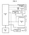
- FIG. 3is a schematic of node for the distributed monitoring and control system of FIG. 1 .
- FIG. 4Ais a schematic illustrating a network of nodes in a distributed monitoring and control system.
- FIG. 4Bis a schematic illustrating network connectivity between the nodes shown in FIG. 4A .
- FIG. 4Cis a schematic illustrating transmission of information within the network shown in FIG. 4B .
- FIG. 4Dis a schematic illustrating the transmission of control instructions within the network shown in FIG. 4C .
- FIG. 4Eis a schematic illustrating the network connectivity and transmission of information within the network shown in FIG. 4C after the failure of some of the nodes.
- FIG. 5is a schematic of a small sewer system and distributed monitoring and control system.
- FIG. 1schematically illustrates a distributed monitoring and control system 10 for monitoring and controlling flow in a combined sewer system.
- the distributed monitoring and control system 10includes a plurality of intercommunicating nodes 12 .
- the communication between the nodes 12is achieved using a wireless transceiver in each of the nodes 12 , as described further below.
- the preferred embodiment of the distributed monitoring and control system 10 described hereinis a wireless system, it is contemplated that wired or hybrid (wired and wireless combination) communication may be utilized to accomplish the distributed monitoring and control system 10 .
- the iNode 14collects information from a sensor 21 .
- the informationis then sent through one or more rNodes 16 to an aNode 18 for controlling flow though the sewer system or to a gNode 20 for connecting to another network.
- any of the nodes 12may perform the function of an iNode 14 , an rNode 16 , an aNode 18 , a gNode 20 , or any combination thereof.
- all nodes 12 in a given distributed monitoring and control system 10may function as rNodes 16 and certain nodes may additionally perform the function of the iNodes 14 , the aNodes 18 and the gNodes 20 .
- each node 12 in the distributed monitoring and control system 10may perform any combination of the functions of any of the different types of nodes 12 , each of the types of nodes 12 will be described separately below.
- the rNodes 16include a microprocessor, a memory and a transceiver, such as, for example, a radio transceiver.
- the main purpose of the rNodes 16is to provide interconnectivity between nodes 12 that cannot communicate directly.
- an rNode 16or a series of rNodes 16 , may function to connect an iNode 14 and an aNode 18 that are geographically separated by a distance greater than their transceivers' range.
- the iNodes 14include the same elements as the rNodes 16 and additionally include a sensor interface.
- the sensor interfaceallows a variety of sensors to be attached to the iNode 14 .
- the sensor interfacecontrols the power delivered to each sensor and allows the iNode's processor to acquire information gathered by the sensor while reducing power consumption when the sensors are not taking measurements.
- the iNodes 14 main purposeis to measure parameters that indicate the hydraulic state of the monitored structure or the pollution content of the wastewater therein.
- an iNode 14may acquire information gathered by an e-coli sensor, a pH sensor, a pressure sensor, a temperature sensor, a conductivity sensor, a dissolved oxygen sensor, etc.
- the aNodes 18include the same elements as the rNodes 16 and additionally include an actuator interface.
- the actuator interfaceallows different types of actuators 23 (see FIG. 2 ) to be attached to the aNode 18 .
- Examples of actuators to be used in the distributed monitoring and control system 10 shown in FIGS. 1 and 2include, without limitation, electric valves, gates, weirs, pumps, lift stations and other general flow controlling devices.
- the gNodes 20include the same elements as the rNodes 16 and additionally include a networking interface.
- the networking interfaceallows the gNodes 20 to connect the wireless network formed by the nodes 12 to another network, such as, for example, a wide area network, a local area network or a cellular data network. Connecting the wireless network of nodes 12 to another network allows an operator or observer to interact with the network or the network data, as well as additional nodes 12 outside of the wireless network. It is contemplated that the gNodes 20 are not essential for the operation of the distributed monitoring and control system 10 , particularly if there is no need to share the information with other networks.
- FIG. 3schematically illustrates an embodiment of one of the iNodes 14 of the distributed monitoring and control system 10 shown in FIGS. 1 and 2 .
- the iNode 14includes a processor 22 , a memory 24 , a transceiver 26 , a power supply 28 and a sensor interface 30 .
- the processor 22is an ATMEGA128 processor operating at 8 MHz. However, it is understood that any processor or plurality of processors may be incorporated into the iNode 14 as the processor 22 .
- the processor 22runs a software application for acquiring data from the sensor through the sensor interface 30 , processes the data and controls the power management and high-level networking layers.
- the processor 22is coupled to a serial interface 36 .
- the serial interfacemay be, for example a keyboard/display interface or a serial connection to be attached to a serial dumb terminal for human interaction. Other uses for the serial connection include debugging and interconnecting with other serial devices.
- the serial interface 36allows a high degree of node programming flexibility and allows for easy debugging, setting and reading program parameters and other general node interface.
- the processor 22is also responsible for the lower levels of networking, the radio management and the memory management. Alternatively, the tasks may be divided in any manner between any number of processors.
- the memory 24 in the embodiment of the iNode 14 shown in FIG. 3 .is an AT45DB161B two megabyte EEPROM. However, it is contemplated other memory may be used in the nodes 12 .
- the memory 24allows large quantities of data acquired from the sensor to be stored allowing the iNode 14 to record data measured by sensors when communication with other nodes 12 is not available, thereby preventing the loss of information. When communication with other nodes 12 is restored, the stored data can then be streamed or extracted from the memory 24 .
- the memory 24may also store main processor program images when network reprogramming is necessary.
- the transceiver 26 in the embodiment of the iNode 14 shown in FIG. 3is a MaxStream radio transceiver 26 operating at 900 MHz or 2.4 GHz depending upon the application.
- the radio transceiver 26allows the use of direct-sequence spread spectrum communication to effectively reduce the possibility of interference. Reliable and robust communication schemes can be implemented to efficiently manage communication between nodes 12 .
- the processor 22controls the transceiver power control.
- the transceiver power controldrastically reduces the power consumption of the transceiver 26 when no events require the transmission of information.
- the use of wireless multihop connectionsallows the use of small transceivers 26 with limited transmission range since it is not necessary to transmit to a distant central location, which allows the use of batteries or solar power to power the nodes 12 .
- a radio bypass 38such as, for example, a UART compatible bypass, allows the iNode 14 to communicate using conventional wired networks when necessary.
- the power supply 28 in the embodiment of the iNode 14 shown in FIG. 3includes a switching power supply 40 and a 6 Volt rechargeable nickel metal hydride battery 42 that allow numerous discharge-charge cycles while retaining its capacity.
- the switching power supply 40regulates the input battery voltage to three different voltages used for the circuitry, namely 3.3 Volts, 5 Volts and 12 Volts.
- the power supply 28enables operation with battery voltages as low as 4 Volts.
- the processor 22monitors the battery condition to alert the system and safely shut down when loss of power occurs. It is contemplated that a battery life of at least twelve months of continuous operation is preferable. Additionally, solar panels can be attached to the recharge battery to allow uninterrupted operation.
- the nodes 12 and other devices connected to the nodes 12may operate using limited power sources, such as, for example, batteries or solar power, in order to allow wireless installation. Although wireless installation can reduce installation costs, it may require aggressive power management. Accordingly, the processor 22 may be programmed with power management software to control power delivery to components such as, for example, sensors 21 , actuators 23 , transceivers 26 , memory 24 and processor 22 . For example, in low power state, the power management software disconnects the power to the sensors 21 , actuators 23 and transceivers 26 and reduces the power provided to the memory 24 and processors 22 , when advantageous. In particular, the power management software only delivers power to the sensors 21 when needed via the sensor interface 30 , which contains MOSFET transistors that connect the power supply 28 to the sensors 21 for short periods of time.
- the sensor interface 30which contains MOSFET transistors that connect the power supply 28 to the sensors 21 for short periods of time.
- FIG. 3specifically illustrates an iNode 14
- the rNodes 16may include the same components, excluding the sensor interface 30 .
- the aNodes 18 and gNodes 20may include the same components excluding the sensor interface 30 , but additionally including an actuator interface in the aNodes 18 and a network interface in the gNodes 20 .
- the processor 22 of each of the nodes 12may be programmed to correspond to the components contained therein.
- the aNodes 18may include an actuator interface capable of generating a 12 Volt pulse modulated signal for controlling a DC electric motor and two current outputs.
- the current outputscan be used to send signals to an actuator 23 using a standard 4-20 mA input interface. Since the aNodes 18 are typically connected to power consuming actuators 23 that require external electrical connection, power management is not as critical in these devices.
- the gNodes 20may be formed by connecting an iNode 14 , an rNode 16 or an aNode 18 to a larger processor board.
- the gNodes 20may be connected to a Technologic Systems TS5600 that features a 133 MHz AMD 586 embedded microprocessor running the Linux operating system.
- the processor boardalso includes a PC card slot that can allocate a 802.11 or WiFi interface card or a cellular modem card.
- the processor boardfurther includes an Ethernet connector. The processor board communicates to the gNode 20 using the serial interface 36 .
- FIGS. 4A-4Eillustrate the robustness of the distributed monitoring and control system 10 .
- robustnessis achieved by using redundant paths, or in other words, the placement of nodes 12 geographically such that each node 12 can communicate with more nodes 12 than necessary to obtain a fully connected and communicating network of nodes 12 .
- the nodes 12employ two types of communication algorithms, broadcasting and routing, each of which is programmed into the processor 22 .
- the broadcasting algorithmallows each node 12 to send a message to every other node 12 .
- the routing algorithmallows each node 12 to send a message to a unique node 12 .
- the processor 22is programmed with an advanced large-scale routing algorithm to ensure network connectivity despite potential failure of one or more nodes 12 .
- the expected internode connectivitywill be low, typically in the range of 60% of data packet throughput between neighboring nodes 12 .
- the data packet throughput between one end of the line to the other using conventional communication algorithmswould be 0.6% or 0.6%. Accordingly, a robust routing algorithm is required to increase throughput in these types of low connectivity networks.
- the distributed monitoring and control system 10 shown in FIGS. 1-4Eincludes a broadcasting algorithm that allows each node 12 to communicate with each of the other nodes 12 in the wireless network, enabling network synchronization and node polling.
- a broadcasting algorithmwhen a node 12 send out a broadcast message, every node 12 that receives the message initiates the broadcasting algorithm.
- Each node 12rebroadcasts the message to increase the probability of communication success.
- each messageis repeated three times.
- the algorithmmay dictate that each node 12 wait a predetermined period of time before trying to rebroadcast the message in order to reduce the probability of message collision with other nodes that are transmitting the originally broadcast message.
- the communication success for an in-line systemis (1-(0.4 ⁇ 3)) 10 or 53%.
- Each data packetcontains data to aid the broadcasting process.
- a hop countermay be used to limit the number of nodes 12 through which a message can travel from its original source. Each time a node 12 transmits a broadcast message data packet, the hop count increases. When the hop counter reaches a predefined value, the data packet gets discarded without being retransmitted.
- An identification numbermay also be appended to the data packet to ensure each message is propagated outward from its origin. The identification number is generated at the origin node by combining the hop counter with the network address of the node 12 . If a node 12 receives a data packet with an identification number that matches the identification number of a previously received message, the data packet gets discarded without being retransmitted.
- timing informationmay be appended to a message to allow each node 12 to calculate the time it took a message received to arrive since being transmitted by the origin node 12 .
- the routing algorithmallows any node 12 in the network to transmit a message to specific nodes 12 within the network designated as data sinks. This feature is particularly useful, for example, for the iNodes 14 that need to send information to specific aNodes 18 or gNodes 20 .
- Each node 12contains a table of the data sinks in the network. Associated with each entry is a number called the gradient. The gradient number is smaller when the node 12 is closer to the data sink. Each data sink itself has a gradient number of 0. When a node 12 is required to transmit a message to a data sink, the node 12 broadcasts the message with its own gradient number and the data sink address appended to the data to be transmitted.
- a node with lower gradient numberreceives the message, it broadcasts an acknowledgement packet, including its own gradient number, to the data sink. If the original message source does not receive an acknowledgement packet with a gradient lower than its own before a specified time it broadcasts again.
- the number of retriescan be specified in the software and may, for example, have a default value of three. If a node 12 receives a packet with a gradient number equal or greater than the senders gradient, the packet may be discarded. Alternatively, additional routes may be established by allowing rebroadcasting when the gradient difference is within an established threshold.
- a node 12after a node 12 has sent an acknowledgement packet, it will rebroadcast the original message with its own gradient number and the process is repeated until the message arrives to its destination, specifically, the node with the matching data sink address. In this way the routing algorithm ensures that the message will approach the destination even if it must branch off in the process and take different routes.
- This type of routing protocolbelongs to a class of stateless routing protocols that are particularly resilient to node failure because it allows the network to function without any node keeping track of information paths. This type of stateless routing protocol avoids the problems associated with gateway based routing protocols.
- a message identification number similar to the one used for the broadcasting algorithmcan be used to prevent the algorithm from using overlapping routes. Also, by enforcing a requirement that the gradient difference between the sender and the rebroadcasting node has to be bigger than a certain threshold, the number of potential routes can be reduced.
- a broadcasting algorithmis used by the data sink nodes 12 to setup routing (or gradient) tables in each node 12 .
- each node 12can establish its number of hops from the data sink. This information is used to generate an appropriate gradient number that is then stored in each node's routing algorithm table together with the data sink address.
- Network synchronizationallows the nodes 12 to undergo alternating cycles of deep sleep mode and active mode in a synchronized fashion. In this way, the nodes 12 may all be active and can perform control and communication activities while in the active mode and otherwise enter deep sleep modes for low power consumption.
- the power consumption in active modescan be up to 2500 times the power consumed in sleep modes. Therefore, it is essential that the nodes 12 remain in sleep mode as long as possible. To achieve this, the nodes 12 enter and leave power cycles in a synchronized fashion.
- the time when all the nodes 12 are in active modeis referred to as the “active window.”
- the active windowcan be a few seconds per cycle, for example, thirty seconds. During the active window all internodal and control algorithms must be executed.
- one node 12 in the network or subnetworkis in charge of synchronization for the entire network or subnetwork. Typically, this node 12 will be a gNode 20 , but it can be any other node 12 . This node 12 is referred to as the synchronization node 12 .
- the synchronization node 12can send out a synchronization packet via the broadcasting algorithm previously described.
- the synchronization packetis sent during the active window.
- the synchronization packetmay include, for example, the time when the request for a new synchronization was issued, the packet traveling time and the sleeping time.
- Each receiving node 12will adjust the remaining active window time to match the one described in the packet by using the traveling time.
- an adaptive power cycle schedulingmay be used to reduce power consumption when wet weather conditions are not forecasted by using a greater amount of time between active windows.
- the sleeping timemay be reduced, allowing critical information about the sewer system to be shared throughout the network on an accelerated schedule.
- the synchronization processmust be performed periodically, typically once a day. Regular synchronization of the internal clocks of the nodes 12 ensures tight synchronization and, therefore, well aligned active windows among all the nodes 12 .
- the low power sleep modemay be executed by a software component within the node 12 that puts the radio transceiver 26 in low power mode, disables the memory 24 , turns the power supply for the sensors 21 off, and stops all timers except for a single unique timer that is used to maintain the adaptive power scheduling cycle.
- a subnetworkcan be formed to include at least one gNode 20 which may communicate with other networks or subnetworks.
- the distributed monitoring and control system 10 shown in FIGS. 4A-4Emay be an independent network or a subnetwork within a larger network.
- the distributed monitoring and control system 10includes a network of nodes 12 .
- the network in FIG. 4Aincludes iNodes 14 , rNodes 16 , and gNodes 20 represented as nodes 12 and three specifically designated aNodes 18 .
- FIG. 4Billustrates one example of network connectivity between the nodes shown in FIG. 4A , such that each of the nodes 12 forms a part of the network.
- the aNodes 18 shown in FIG. 4Amay request sensor information from iNodes 14 .
- FIG. 4Cillustrates the flow of sensor information through the network to the aNodes 18 .
- FIG. 4Dshows the aNodes 18 communicating with each other to make a decision based on the combined information.
- FIG. 4Edemonstrates the robustness of the network of nodes 12 by illustrating the network connectivity and transmission of information within the network shown in FIG. 4C after the failure of multiple nodes 12 .
- the failed nodes 12disrupt the original communication paths formed as shown in FIG. 4B .
- each of the aNodes 18remain in contact with each other and are able to collect information from and through each of the functioning nodes 12 .
- the routing algorithms programmed into the nodes 12enable the nodes 12 to automatically rebuild the network connectivity upon deployment or failure of one or more nodes 12 .
- the distributed monitoring and control system 10can be implemented to reduce the occurrence of combined sewer overflow (CSO) events. In order to reduce the occurrence of CSO events, the distributed monitoring and control system 10 performs two functions: monitoring and actuation. Similarly, the distributed monitoring and control system 10 can be implemented to maximize system performance, optimize collector pipes capacity, flush sewer pipes to reduce solids attached to pipe walls, divert flow to other locations and to reduce sewer overflow to other external systems, such as, for example, a treatment facility.
- CSOcombined sewer overflow
- the monitoring function of the distributed monitoring and control system 10is accomplished using the information acquired through the iNodes 14 .
- the iNodes 14may measure hydraulic parameters of a sewer system, such as, for example, flow of waste or water through a pipe, the level of water in a basin, etc.
- redundant sensorsmay be used in conjunction with a consensus algorithm to accurate determine the status of the hydraulic parameters. Redundancy in the collection of information allows the distributed monitoring and control system 10 to be robust to failure of the iNodes 14 . With redundancy, the measurements from each iNode 14 are less important than the aggregation of the information from the overlapping sensors.
- the distributed monitoring and control system 10can be configured to tune the accuracy of the measurements to the number of nodes 12 performing overlapping measurements to ensure sufficient accuracy.
- the data collected by the iNodes 14is routed through the network of nodes, as shown in FIGS. 4A-4E , to the relevant aNodes 18 and gNodes 20 .
- the actuation function of the distributed monitoring and control system 10is accomplished by the aNodes 18 or other nodes 12 including the functionality described above with respect to the aNodes 18 .
- the actuation functionmay be carried out by a node 12 that incorporates the functions of both the aNode 18 and the gNode 20 described above.
- the control actions performed by the aNodes 18are determined using a model-based distributed system control algorithm incorporating a model of the combined sewer system. Each aNode 18 receives the relevant information from the surrounding nodes 12 to make its own control command decision.
- the model-based distributed system control algorithmfurther enhances the robustness of the distributed monitoring and control system 10 and enables the distributed monitoring and control system 10 to operate with limited amount of communication between nodes 12 .
- Limited communicationis key to the aggressive power management schemes described above.
- limited communicationrequires limited bandwidth to operate the wireless network of nodes 12 , further improving the cost effectiveness and robustness of the distributed monitoring and control system 10 .
- Using a model-based distributed system control algorithmfurther allows the distributed monitoring and control system 10 to operate in a distributed fashion.
- the distributed monitoring and control system 10does not require a central computing element to process the data from the entire system to determine and execute control commands.
- the distributed monitoring and control system 10is capable of being employed to monitor and control massive amounts of information and geography.
- FIG. 5A small sewer network including a distributed monitoring and control system 100 is shown in FIG. 5 .
- Reservoir Ta 102 and reservoir Tb 104represent retention basins or other retention structures.
- a link element 106for example a length of sewer pipe, is provided having a flow transport delay of one unit of time.
- Another link element 108is provided having a flow transport delay of two units of time.
- Reservoir Te 110receives the flow from reservoir Ta 102 and reservoir Tb 104 .
- the input flowis represented in FIG. 5 by Ua 112 and Ub 114 and the output flow (for example, to a water treatment facility) is represented by Qe 116 .
- the flows Qa 118 , Qb 120 and Qe 122are controlled flows using aNodes 18 , as described above with respect to FIGS.
- This equation systemcan be further represented in the form of a traditional discrete linear time invariant state space equation with unknown disturbances Ua and Ub:
- the mathematical description of the sewer elementscan be made more accurate by utilizing more detailed mathematical descriptions of the individual elements.
- the above simplified systemis used here for clarity of the control approach used.
- the region over which the system is allowed to evolveis constraint as a result of limitations in the actual system such as maximum height in the reservoirs or maximum flow capacity in the pipes.
- control strategiescan be calculated to maximize the use of the reservoirs during rain event, thus reducing flow directed to the water treatment facility.
- Networked model-based techniquessuch as the ones described in Ref. Handbook of Networked and Embedded Control Systems, 2005, Birkophen, pp. 601-625, the entirety of which is incorporated herein by reference, can be used to determine the appropriate control strategy for the linearized system presented with reference to FIG. 5 , or more detailed non-linear systems.
- a price-based controlcan, for example, be implemented to stagger the operation of the actuators 23 connected to the aNodes 18 in a manner that maximizes the power of the water flowing through the sewer network. This is accomplished by having each of the aNodes 18 make local decisions about actuation on the basis of the head measured by the nodes 12 immediately upstream and downstream from each aNode 18 . Because an individual aNode's 18 control decision is based only on the head of its immediate upstream/downstream nodes 12 , this control strategy is highly decentralized
- the price-based model predictive control algorithmmay use a decentralized approach to solve the following flow optimization problem
- the optimization problemseeks to maximize the integrated flow power, x T D T q, discounted by the square of the head levels, x T x. This maximization is done subject to a constraint that the flow rate, q, is bounded above by the function, Q(D T x), which relates flow rate, q, to the difference between the head levels in a pipe's upstream and downstream manhole.
- Q(D T x)which relates flow rate, q, to the difference between the head levels in a pipe's upstream and downstream manhole.
- the second constraintis a differential equation that requires the rate of change in the head equal the total inflows into the manhole minus the total outflows from the manhole.
- the flow optimization problem shown aboveis an optimal control problem whose solution via Pontryagin's maximum principle yields an optimal flow of the form
- q j *⁇ d j ⁇ x if ⁇ ⁇ ⁇ d j ⁇ ( x - p ) ⁇ 0 otherwise
- d iis the jth row of the incidence matrix D
- x and pare time-varying functions satisfying a two-point boundary value problem (“TPBVP”).
- TTBVPtwo-point boundary value problem
- the function xrepresents the head in the sewer system nodes 12 .
- the function palso called the co-state
- the control lawsays that if the head difference exceeds a level set by the price, p, then the corresponding aNode 18 should increase flow, otherwise the flow should be decreased or stopped.
- the strategycontrols the nodes' 12 outflows in a way that maximizes the difference between the head of two adjacent nodes 12 .
- Model-predictive (also called receding horizon) controlgenerates a sequence of controls that are optimal over a finite horizon of length T.
- this stabilization techniqueit can be assured that this sequence asymptotically converges to the solution of an infinite-horizon optimization problem for any choice of horizon, T. Since the computational complexity associated with solving the TPBVP decreases with smaller T, the use of the stabilized receding horizon controller allows us to develop a computationally tractable control algorithm that is well suited to processing power of the nodes 12 .
- the system provided with reference to FIG. 5can be divided into three coupled systems (one for each reservoir), each with its own set of inputs, outputs, and disturbances.
- the control systems from reservoir Ta 102 and reservoir Tb 104can independently calculate their control strategy based on information provided by the control system serving reservoir Te 110 . This is accomplished by doing a feasibility analysis to determine bounds on the flow Qc, after which the control systems of Ta and Tb agree on values for Qa and Qb.
- the values for Qa and Qbmay be based, for example, on parameters such as percentage of reservoir used. It is understood that the outlined control strategy is only one of the several that can be applied to solve the control problem.
- the distributed monitoring and control system 10may be adapted to address various environmental, security, engineering and other problems.
- a distributed monitoring and control systemmay be used for tracking and monitoring people, vehicles and animals, for traffic control, as a forest fire early warning system, for fire or harmful gas detection, for inventory monitoring, for structural integrity monitoring or any other system in which distributed monitoring and control may be advantageous.
- the sensors, actuators and algorithms described abovemay be adapted to the problems associated with the particular application.
Landscapes
- Engineering & Computer Science (AREA)
- Health & Medical Sciences (AREA)
- Computer Networks & Wireless Communication (AREA)
- Signal Processing (AREA)
- Computing Systems (AREA)
- General Health & Medical Sciences (AREA)
- Medical Informatics (AREA)
- Life Sciences & Earth Sciences (AREA)
- Hydrology & Water Resources (AREA)
- Public Health (AREA)
- Water Supply & Treatment (AREA)
- Selective Calling Equipment (AREA)
Abstract
Description
ha(k+1)=ha(k)+(ua(k)−qa(k))Ta
hb(k+1)=hb(k)+(ub(k)−qb(k))Tb
qc(k+1)=qa(k+1)+qb(k)
qd(k+2)=qc(k)
he(k+1)=he(k)+(qd(k)−qe(k))
where x is a real vector whose components represent the head in the sewer network and q is a real vector whose components represent the flow rates in the sewer network. D is an incidence matrix for the directed graph formed by the sewer system, for example, the manholes and pipes. The optimization problem seeks to maximize the integrated flow power, xTDTq, discounted by the square of the head levels, xTx. This maximization is done subject to a constraint that the flow rate, q, is bounded above by the function, Q(DTx), which relates flow rate, q, to the difference between the head levels in a pipe's upstream and downstream manhole. The second constraint is a differential equation that requires the rate of change in the head equal the total inflows into the manhole minus the total outflows from the manhole.
where diis the jth row of the incidence matrix D and where x and p are time-varying functions satisfying a two-point boundary value problem (“TPBVP”). The function x represents the head in the
Claims (19)
Priority Applications (1)
| Application Number | Priority Date | Filing Date | Title |
|---|---|---|---|
| US11/437,384US7792126B1 (en) | 2005-05-19 | 2006-05-19 | Distributed monitoring and control system |
Applications Claiming Priority (2)
| Application Number | Priority Date | Filing Date | Title |
|---|---|---|---|
| US68238405P | 2005-05-19 | 2005-05-19 | |
| US11/437,384US7792126B1 (en) | 2005-05-19 | 2006-05-19 | Distributed monitoring and control system |
Publications (1)
| Publication Number | Publication Date |
|---|---|
| US7792126B1true US7792126B1 (en) | 2010-09-07 |
Family
ID=42669684
Family Applications (1)
| Application Number | Title | Priority Date | Filing Date |
|---|---|---|---|
| US11/437,384Active2028-10-07US7792126B1 (en) | 2005-05-19 | 2006-05-19 | Distributed monitoring and control system |
Country Status (1)
| Country | Link |
|---|---|
| US (1) | US7792126B1 (en) |
Cited By (28)
| Publication number | Priority date | Publication date | Assignee | Title |
|---|---|---|---|---|
| US20090310623A1 (en)* | 2006-09-14 | 2009-12-17 | Edelcom | Method and device for transmitting information over a complex network |
| US20100070097A1 (en)* | 2008-09-18 | 2010-03-18 | Paul Morgenstern | Remotely controlled fire protection system |
| US20100271989A1 (en)* | 2009-04-23 | 2010-10-28 | Honeywell International Inc. | Wireless controller grids for process control and other systems and related apparatus and method |
| US20110071773A1 (en)* | 2007-10-23 | 2011-03-24 | Saylor David J | Method and Device for the Assessment of Fluid Collection Networks |
| US20110148631A1 (en)* | 2009-12-21 | 2011-06-23 | Mcgard Llc | Manhole Security Cover |
| US20110307106A1 (en)* | 2010-06-14 | 2011-12-15 | Kevin Charles Dutt | Methods and Systems for Monitoring, Controlling, and Recording Performance of a Storm Water Runoff Network |
| US20120106561A1 (en)* | 2010-10-29 | 2012-05-03 | Canon Kabushiki Kaisha | Communication system, control station thereof and communication method |
| US20120327831A1 (en)* | 2010-03-04 | 2012-12-27 | Quantislabs Ltd | System and method for wireless sensor networks |
| US20130234862A1 (en)* | 2011-08-19 | 2013-09-12 | University Of North Florida Board Of Trustees | Street Light Monitoring System |
| WO2013153312A1 (en)* | 2012-04-13 | 2013-10-17 | Veolia Proprete | Device for regulating the flow rate of a fluid in a pipe of a network of pipes |
| US20150019146A1 (en)* | 2013-07-15 | 2015-01-15 | EmNet, LLC | Sewer overflow discharge monitoring system and method |
| US20150025868A1 (en)* | 2013-04-30 | 2015-01-22 | International Business Machines Corporation | Combined sewer overflow warning and prevention system |
| US9127431B2 (en) | 2010-10-07 | 2015-09-08 | Mcgard Llc | Manhole security cover |
| CN105427566A (en)* | 2015-12-09 | 2016-03-23 | 华南理工大学 | Wind power plant remote real-time monitoring system and method based on wireless sensor network |
| US20160378123A1 (en)* | 2015-02-06 | 2016-12-29 | Luis Montestruque | System and method for agent-based control of sewer infrastructure |
| US9699022B2 (en) | 2014-08-01 | 2017-07-04 | Honeywell International Inc. | System and method for controller redundancy and controller network redundancy with ethernet/IP I/O |
| CN107393267A (en)* | 2017-07-18 | 2017-11-24 | 陈剑桃 | A kind of sewage intelligent monitoring management system |
| US20170346651A1 (en)* | 2015-01-19 | 2017-11-30 | WATER MANAGER S.à.R.L | Scalable system and methods for monitoring and controlling a sanitary facility using distributed connected devices |
| US20180113481A1 (en)* | 2016-10-21 | 2018-04-26 | John Faiczak | Method, apparatus and system for balancing the fluid pressure of fluid distribution systems |
| US10042330B2 (en) | 2014-05-07 | 2018-08-07 | Honeywell International Inc. | Redundant process controllers for segregated supervisory and industrial control networks |
| US20180364692A1 (en)* | 2017-06-15 | 2018-12-20 | International Business Machines Corporation | Enhanced service procedures using force measurement |
| US10197982B2 (en)* | 2015-06-03 | 2019-02-05 | Eric Sari | Machine control unit |
| US10296482B2 (en) | 2017-03-07 | 2019-05-21 | Honeywell International Inc. | System and method for flexible connection of redundant input-output modules or other devices |
| US10687389B2 (en) | 2018-01-29 | 2020-06-16 | Honeywell International Inc. | Wireless industrial remote controller for industrial process control and automation systems or other systems |
| WO2021204943A3 (en)* | 2020-04-09 | 2021-12-02 | Bundesdruckerei Gmbh | Monitoring system with multistage request verification |
| EP3926243A1 (en)* | 2020-06-18 | 2021-12-22 | John Faiczak | Method, apparatus and system for balancing the fluid pressure of fluid distribution systems |
| CN115046591A (en)* | 2022-06-27 | 2022-09-13 | 大连莱克科技发展有限公司 | Modularization distributing type temperature flow measuring device |
| CN116455998A (en)* | 2023-04-20 | 2023-07-18 | 列宿(苏州)智能科技有限公司 | A Multi-Heterogeneous Agent Anti-interference Cooperative Control Algorithm for Polling Protocol |
Citations (72)
| Publication number | Priority date | Publication date | Assignee | Title |
|---|---|---|---|---|
| US3638490A (en) | 1969-01-17 | 1972-02-01 | Carl F Buettner | Fluid flow measuring device |
| US4026151A (en) | 1976-05-10 | 1977-05-31 | Fitzgerald Joseph C | Measuring device for water flow in a buried pipe |
| US4058011A (en) | 1974-09-05 | 1977-11-15 | Pro-Tech, Inc. | Flow monitoring apparatus |
| US4070563A (en) | 1975-08-08 | 1978-01-24 | Petroff Peter D | Infiltration-inflow sewer line analyzer |
| US4150683A (en) | 1977-08-22 | 1979-04-24 | Wilbur Simon | Elimination of overflow of sewer systems |
| US4188968A (en) | 1977-10-28 | 1980-02-19 | Johnson Controls, Inc. | Flow system with pressure level responsive air admission control |
| US4200911A (en) | 1976-10-20 | 1980-04-29 | Hitachi, Ltd. | Control of the flow rate and fluid pressure in a pipeline network for optimum distribution of the fluid to consumers |
| US4211111A (en) | 1977-06-30 | 1980-07-08 | Petroff Peter D | Infiltration-inflow sewer line analyzer |
| US4221127A (en) | 1978-01-11 | 1980-09-09 | Mcclure Charles A | Flow monitoring |
| US4258747A (en) | 1979-04-02 | 1981-03-31 | Johnson Controls, Inc. | Flow system with pressure level interlock control apparatus |
| US4268383A (en) | 1979-03-26 | 1981-05-19 | Johnson Controls, Inc. | Flow system control with time delay override means |
| US4295197A (en) | 1978-05-12 | 1981-10-13 | Petroff Peter D | Infiltration-inflow sewer line analyzer |
| US4344329A (en) | 1979-12-17 | 1982-08-17 | Petroff Peter D | Flow analyzer |
| US4386409A (en) | 1980-09-23 | 1983-05-31 | Petroff Alan M | Sewage flow monitoring system |
| US4407158A (en) | 1979-12-17 | 1983-10-04 | Petroff Peter D | Flow analyzer |
| US4571997A (en) | 1984-06-21 | 1986-02-25 | Professional Associated Consulting Engineers Incorporated | Flow measuring apparatus |
| US4630474A (en) | 1975-08-08 | 1986-12-23 | Petroff Peter D | Flow analyzer |
| US4892440A (en) | 1988-07-05 | 1990-01-09 | Eveready Flood Control | Water backup preventing system and monitoring system therefor |
| US4987913A (en)* | 1988-06-25 | 1991-01-29 | Kabushiki Kaisha Toshiba | Apparatus and method for controlling operation of storm sewage pump |
| US4997312A (en) | 1988-07-05 | 1991-03-05 | Patrick Regan | Water backup preventing system and monitoring system therefor |
| US5020374A (en) | 1989-11-17 | 1991-06-04 | Ads Environmental Services, Inc. | Velocity measurement system |
| US5161911A (en) | 1988-07-05 | 1992-11-10 | Patrick Regan | Water backup preventing system and monitoring system therefor |
| US5198989A (en) | 1980-09-23 | 1993-03-30 | Ads Environmental Services, Inc. | Sewer flow measurement control system |
| US5321601A (en) | 1992-02-28 | 1994-06-14 | Riedel Dennis S | Apparatus for controlling flow in a sewer regulator |
| US5342144A (en)* | 1992-11-02 | 1994-08-30 | Mccarthy Edward J | Stormwater control system |
| US5365423A (en)* | 1992-01-08 | 1994-11-15 | Rockwell International Corporation | Control system for distributed sensors and actuators |
| US5371859A (en)* | 1990-01-22 | 1994-12-06 | Lennartsson; Kent | System for providing data communications between a plurality of measurement data generating/receiving modules connected to a common communication bus |
| US5423226A (en) | 1993-11-16 | 1995-06-13 | Yellowstone Environmental Science, Inc. | Flow measurement system |
| US5448476A (en) | 1993-06-17 | 1995-09-05 | Kabushiki Kaisha Toshiba | Distributed water flow predicting device |
| US5506791A (en) | 1989-12-22 | 1996-04-09 | American Sigma, Inc. | Multi-function flow monitoring apparatus with multiple flow sensor capability |
| US5608171A (en)* | 1993-11-16 | 1997-03-04 | Hunter; Robert M. | Distributed, unattended wastewater monitoring system |
| US5633809A (en) | 1989-12-22 | 1997-05-27 | American Sigma, Inc. | Multi-function flow monitoring apparatus with area velocity sensor capability |
| US5684250A (en) | 1995-08-21 | 1997-11-04 | Marsh-Mcbirney, Inc. | Self-calibrating open-channel flowmeter |
| US5834659A (en) | 1995-02-03 | 1998-11-10 | Lockheed Martin Idaho Technologies Company | Device and method for measuring fluid flow in a conduit having a gradual bend |
| US5835836A (en) | 1997-03-19 | 1998-11-10 | Fujitsu Limited | Image forming apparatus |
| US5870692A (en) | 1997-01-10 | 1999-02-09 | Systemes Integres Abdmf Inc. | Effluent monitoring system |
| US5874903A (en)* | 1997-06-06 | 1999-02-23 | Abb Power T & D Company Inc. | RF repeater for automatic meter reading system |
| US5905208A (en) | 1995-02-03 | 1999-05-18 | Lockheed Martin Idhao Technologies Company | System and method measuring fluid flow in a conduit |
| US5942698A (en) | 1997-11-19 | 1999-08-24 | Ads Environmental Services, Inc. | Detecting and measuring liquid flow in remote sewer structures |
| US5978364A (en)* | 1996-02-29 | 1999-11-02 | Philips Electronics North America Corporation | Method for routing data packets within a wireless, packet-hopping network and a wireless network for implementing the same |
| US5979493A (en) | 1996-08-02 | 1999-11-09 | Gary A. Isaacson, Jr. | Flood control device |
| US6009762A (en) | 1994-04-29 | 2000-01-04 | Ockleston; Grant Andrew | Fluid flow detector |
| US6021664A (en) | 1998-01-29 | 2000-02-08 | The United States Of America As Represented By The Secretary Of The Interior | Automated groundwater monitoring system and method |
| US6082925A (en) | 1999-06-29 | 2000-07-04 | Raasch; Jason J. | Storm sewer overflow control device |
| US6216543B1 (en) | 1997-03-28 | 2001-04-17 | Bio Merieux | Method and device for controlling liquid fluxes in pipes lines |
| US6317051B1 (en) | 1998-08-03 | 2001-11-13 | Jeffrey D. Cohen | Water flow monitoring system determining the presence of leaks and stopping flow in water pipes |
| US6318395B1 (en) | 1999-11-10 | 2001-11-20 | Aquaflow Technologies, Llc | Method and apparatus for sewer system flow control to reduce wastewater treatment electrical costs |
| US20020035497A1 (en) | 2000-06-09 | 2002-03-21 | Jeff Mazereeuw | System and method for utility enterprise management |
| US6406216B1 (en) | 2000-07-07 | 2002-06-18 | Jason J. Raasch | Storm sewer overflow control device |
| US20020094799A1 (en) | 2000-01-31 | 2002-07-18 | Elliott Karl E. | Wireless communication enabled meter and network |
| US6437692B1 (en)* | 1998-06-22 | 2002-08-20 | Statsignal Systems, Inc. | System and method for monitoring and controlling remote devices |
| US6474153B1 (en) | 1999-03-09 | 2002-11-05 | Kabushiki Kaisha Toshiba | Predicting system and predicting method configured to predict inflow volume of rainwater |
| US20020170350A1 (en) | 2001-05-18 | 2002-11-21 | Schutzbach James S. | Method and system for analyzing the effect of inflow and infiltration on a sewer system |
| US6498968B1 (en)* | 2001-11-27 | 2002-12-24 | Lockheed Martin Corporation | Optimistic distributed simulation for a UAV flight control system |
| US6558077B1 (en)* | 2001-03-16 | 2003-05-06 | Cameron M. Colson | Selective suspension drain closure apparatus |
| US6565284B2 (en) | 2000-12-08 | 2003-05-20 | Stephen V. Gearhart | Infiltration control system and method |
| US6618648B1 (en) | 1998-03-05 | 2003-09-09 | Kabushiki Kaisha Toshiba | Control system method of protectively controlling electric power system and storage medium storing program code |
| US6638424B2 (en) | 2000-01-19 | 2003-10-28 | Jensen Enterprises | Stormwater treatment apparatus |
| US20030236639A1 (en) | 2002-03-26 | 2003-12-25 | Curry Lynn Burton | Sewer flow analysis method |
| US6696961B2 (en) | 2001-12-21 | 2004-02-24 | Kenneth J. Uhler | Water damage protection system and method of preventing water damage for domestic water supply systems |
| US6701261B2 (en) | 2002-05-17 | 2004-03-02 | Ads Corporation | Method and system for analyzing the effect of inflow and infiltration on a sewer system |
| US6757623B2 (en) | 2001-04-20 | 2004-06-29 | Ads Corporation | Flow transport analysis method and system |
| US6807494B2 (en) | 2001-03-09 | 2004-10-19 | Ads Corporation | Sewer flow monitoring method and system |
| US6823729B2 (en) | 2002-05-06 | 2004-11-30 | Brombach Hansjoerg | Measuring weir for measuring flow volume at an overflow |
| US20040239523A1 (en) | 2003-06-02 | 2004-12-02 | Paoli Ernie R. | Wireless remote monitoring system |
| US20050005093A1 (en) | 2003-07-01 | 2005-01-06 | Andrew Bartels | Methods, systems and devices for securing supervisory control and data acquisition (SCADA) communications |
| US6862498B2 (en) | 2001-08-15 | 2005-03-01 | Statsignal Systems, Inc. | System and method for controlling power demand over an integrated wireless network |
| US20050071139A1 (en) | 2003-09-29 | 2005-03-31 | Patwardhan Avinash S. | Method and system for water flow analysis |
| US20050072465A1 (en) | 2003-10-02 | 2005-04-07 | Preul Herbert C. | Wastewater control system |
| US20050072469A1 (en) | 2003-10-02 | 2005-04-07 | Preul Herbert C. | Wastewater source control system |
| US6914893B2 (en) | 1998-06-22 | 2005-07-05 | Statsignal Ipc, Llc | System and method for monitoring and controlling remote devices |
| US20060164771A1 (en)* | 2002-08-16 | 2006-07-27 | Sebastian Heidepriem | Device for transmitting, exchanging and/or routing data and/or information |
- 2006
- 2006-05-19USUS11/437,384patent/US7792126B1/enactiveActive
Patent Citations (75)
| Publication number | Priority date | Publication date | Assignee | Title |
|---|---|---|---|---|
| US3638490A (en) | 1969-01-17 | 1972-02-01 | Carl F Buettner | Fluid flow measuring device |
| US4058011A (en) | 1974-09-05 | 1977-11-15 | Pro-Tech, Inc. | Flow monitoring apparatus |
| US4070563A (en) | 1975-08-08 | 1978-01-24 | Petroff Peter D | Infiltration-inflow sewer line analyzer |
| US4116061A (en) | 1975-08-08 | 1978-09-26 | Petroff Peter D | Sewer line analyzer probe |
| US4630474A (en) | 1975-08-08 | 1986-12-23 | Petroff Peter D | Flow analyzer |
| US4026151A (en) | 1976-05-10 | 1977-05-31 | Fitzgerald Joseph C | Measuring device for water flow in a buried pipe |
| US4200911A (en) | 1976-10-20 | 1980-04-29 | Hitachi, Ltd. | Control of the flow rate and fluid pressure in a pipeline network for optimum distribution of the fluid to consumers |
| US4211111A (en) | 1977-06-30 | 1980-07-08 | Petroff Peter D | Infiltration-inflow sewer line analyzer |
| US4150683A (en) | 1977-08-22 | 1979-04-24 | Wilbur Simon | Elimination of overflow of sewer systems |
| US4188968A (en) | 1977-10-28 | 1980-02-19 | Johnson Controls, Inc. | Flow system with pressure level responsive air admission control |
| US4221127A (en) | 1978-01-11 | 1980-09-09 | Mcclure Charles A | Flow monitoring |
| US4295197A (en) | 1978-05-12 | 1981-10-13 | Petroff Peter D | Infiltration-inflow sewer line analyzer |
| US4268383A (en) | 1979-03-26 | 1981-05-19 | Johnson Controls, Inc. | Flow system control with time delay override means |
| US4258747A (en) | 1979-04-02 | 1981-03-31 | Johnson Controls, Inc. | Flow system with pressure level interlock control apparatus |
| US4407158A (en) | 1979-12-17 | 1983-10-04 | Petroff Peter D | Flow analyzer |
| US4344329A (en) | 1979-12-17 | 1982-08-17 | Petroff Peter D | Flow analyzer |
| US4386409A (en) | 1980-09-23 | 1983-05-31 | Petroff Alan M | Sewage flow monitoring system |
| US5198989A (en) | 1980-09-23 | 1993-03-30 | Ads Environmental Services, Inc. | Sewer flow measurement control system |
| US4571997A (en) | 1984-06-21 | 1986-02-25 | Professional Associated Consulting Engineers Incorporated | Flow measuring apparatus |
| US4987913A (en)* | 1988-06-25 | 1991-01-29 | Kabushiki Kaisha Toshiba | Apparatus and method for controlling operation of storm sewage pump |
| US4997312A (en) | 1988-07-05 | 1991-03-05 | Patrick Regan | Water backup preventing system and monitoring system therefor |
| US5161911A (en) | 1988-07-05 | 1992-11-10 | Patrick Regan | Water backup preventing system and monitoring system therefor |
| US4892440A (en) | 1988-07-05 | 1990-01-09 | Eveready Flood Control | Water backup preventing system and monitoring system therefor |
| US5020374A (en) | 1989-11-17 | 1991-06-04 | Ads Environmental Services, Inc. | Velocity measurement system |
| US5633809A (en) | 1989-12-22 | 1997-05-27 | American Sigma, Inc. | Multi-function flow monitoring apparatus with area velocity sensor capability |
| US5506791A (en) | 1989-12-22 | 1996-04-09 | American Sigma, Inc. | Multi-function flow monitoring apparatus with multiple flow sensor capability |
| US5371859A (en)* | 1990-01-22 | 1994-12-06 | Lennartsson; Kent | System for providing data communications between a plurality of measurement data generating/receiving modules connected to a common communication bus |
| US5365423A (en)* | 1992-01-08 | 1994-11-15 | Rockwell International Corporation | Control system for distributed sensors and actuators |
| US5321601A (en) | 1992-02-28 | 1994-06-14 | Riedel Dennis S | Apparatus for controlling flow in a sewer regulator |
| US5342144A (en)* | 1992-11-02 | 1994-08-30 | Mccarthy Edward J | Stormwater control system |
| US5448476A (en) | 1993-06-17 | 1995-09-05 | Kabushiki Kaisha Toshiba | Distributed water flow predicting device |
| US5608171A (en)* | 1993-11-16 | 1997-03-04 | Hunter; Robert M. | Distributed, unattended wastewater monitoring system |
| US5423226A (en) | 1993-11-16 | 1995-06-13 | Yellowstone Environmental Science, Inc. | Flow measurement system |
| US6009762A (en) | 1994-04-29 | 2000-01-04 | Ockleston; Grant Andrew | Fluid flow detector |
| US5834659A (en) | 1995-02-03 | 1998-11-10 | Lockheed Martin Idaho Technologies Company | Device and method for measuring fluid flow in a conduit having a gradual bend |
| US5886267A (en) | 1995-02-03 | 1999-03-23 | Lockheed Martin Idaho Technologies Company | System and method for bidirectional flow and controlling fluid flow in a conduit |
| US5905208A (en) | 1995-02-03 | 1999-05-18 | Lockheed Martin Idhao Technologies Company | System and method measuring fluid flow in a conduit |
| US5684250A (en) | 1995-08-21 | 1997-11-04 | Marsh-Mcbirney, Inc. | Self-calibrating open-channel flowmeter |
| US5978364A (en)* | 1996-02-29 | 1999-11-02 | Philips Electronics North America Corporation | Method for routing data packets within a wireless, packet-hopping network and a wireless network for implementing the same |
| US5979493A (en) | 1996-08-02 | 1999-11-09 | Gary A. Isaacson, Jr. | Flood control device |
| US5870692A (en) | 1997-01-10 | 1999-02-09 | Systemes Integres Abdmf Inc. | Effluent monitoring system |
| US5835836A (en) | 1997-03-19 | 1998-11-10 | Fujitsu Limited | Image forming apparatus |
| US6216543B1 (en) | 1997-03-28 | 2001-04-17 | Bio Merieux | Method and device for controlling liquid fluxes in pipes lines |
| US5874903A (en)* | 1997-06-06 | 1999-02-23 | Abb Power T & D Company Inc. | RF repeater for automatic meter reading system |
| US5942698A (en) | 1997-11-19 | 1999-08-24 | Ads Environmental Services, Inc. | Detecting and measuring liquid flow in remote sewer structures |
| US6021664A (en) | 1998-01-29 | 2000-02-08 | The United States Of America As Represented By The Secretary Of The Interior | Automated groundwater monitoring system and method |
| US6618648B1 (en) | 1998-03-05 | 2003-09-09 | Kabushiki Kaisha Toshiba | Control system method of protectively controlling electric power system and storage medium storing program code |
| US6437692B1 (en)* | 1998-06-22 | 2002-08-20 | Statsignal Systems, Inc. | System and method for monitoring and controlling remote devices |
| US6914893B2 (en) | 1998-06-22 | 2005-07-05 | Statsignal Ipc, Llc | System and method for monitoring and controlling remote devices |
| US6317051B1 (en) | 1998-08-03 | 2001-11-13 | Jeffrey D. Cohen | Water flow monitoring system determining the presence of leaks and stopping flow in water pipes |
| US6474153B1 (en) | 1999-03-09 | 2002-11-05 | Kabushiki Kaisha Toshiba | Predicting system and predicting method configured to predict inflow volume of rainwater |
| US6082925A (en) | 1999-06-29 | 2000-07-04 | Raasch; Jason J. | Storm sewer overflow control device |
| US6318395B1 (en) | 1999-11-10 | 2001-11-20 | Aquaflow Technologies, Llc | Method and apparatus for sewer system flow control to reduce wastewater treatment electrical costs |
| US6638424B2 (en) | 2000-01-19 | 2003-10-28 | Jensen Enterprises | Stormwater treatment apparatus |
| US20020094799A1 (en) | 2000-01-31 | 2002-07-18 | Elliott Karl E. | Wireless communication enabled meter and network |
| US20020035497A1 (en) | 2000-06-09 | 2002-03-21 | Jeff Mazereeuw | System and method for utility enterprise management |
| US6406216B1 (en) | 2000-07-07 | 2002-06-18 | Jason J. Raasch | Storm sewer overflow control device |
| US6565284B2 (en) | 2000-12-08 | 2003-05-20 | Stephen V. Gearhart | Infiltration control system and method |
| US6807494B2 (en) | 2001-03-09 | 2004-10-19 | Ads Corporation | Sewer flow monitoring method and system |
| US6558077B1 (en)* | 2001-03-16 | 2003-05-06 | Cameron M. Colson | Selective suspension drain closure apparatus |
| US6757623B2 (en) | 2001-04-20 | 2004-06-29 | Ads Corporation | Flow transport analysis method and system |
| US20020170350A1 (en) | 2001-05-18 | 2002-11-21 | Schutzbach James S. | Method and system for analyzing the effect of inflow and infiltration on a sewer system |
| US6862498B2 (en) | 2001-08-15 | 2005-03-01 | Statsignal Systems, Inc. | System and method for controlling power demand over an integrated wireless network |
| US6498968B1 (en)* | 2001-11-27 | 2002-12-24 | Lockheed Martin Corporation | Optimistic distributed simulation for a UAV flight control system |
| US6696961B2 (en) | 2001-12-21 | 2004-02-24 | Kenneth J. Uhler | Water damage protection system and method of preventing water damage for domestic water supply systems |
| US20030236639A1 (en) | 2002-03-26 | 2003-12-25 | Curry Lynn Burton | Sewer flow analysis method |
| US6823729B2 (en) | 2002-05-06 | 2004-11-30 | Brombach Hansjoerg | Measuring weir for measuring flow volume at an overflow |
| US6832166B2 (en) | 2002-05-17 | 2004-12-14 | Ads Corporation | Method and system for analyzing the effect of inflow and infiltration on a sewer system |
| US6701261B2 (en) | 2002-05-17 | 2004-03-02 | Ads Corporation | Method and system for analyzing the effect of inflow and infiltration on a sewer system |
| US20060164771A1 (en)* | 2002-08-16 | 2006-07-27 | Sebastian Heidepriem | Device for transmitting, exchanging and/or routing data and/or information |
| US20040239523A1 (en) | 2003-06-02 | 2004-12-02 | Paoli Ernie R. | Wireless remote monitoring system |
| US20050005093A1 (en) | 2003-07-01 | 2005-01-06 | Andrew Bartels | Methods, systems and devices for securing supervisory control and data acquisition (SCADA) communications |
| US20050071139A1 (en) | 2003-09-29 | 2005-03-31 | Patwardhan Avinash S. | Method and system for water flow analysis |
| US20050072465A1 (en) | 2003-10-02 | 2005-04-07 | Preul Herbert C. | Wastewater control system |
| US20050072469A1 (en) | 2003-10-02 | 2005-04-07 | Preul Herbert C. | Wastewater source control system |
Cited By (43)
| Publication number | Priority date | Publication date | Assignee | Title |
|---|---|---|---|---|
| US20090310623A1 (en)* | 2006-09-14 | 2009-12-17 | Edelcom | Method and device for transmitting information over a complex network |
| US7995592B2 (en)* | 2006-09-14 | 2011-08-09 | Edelcom | Method and device for transmitting information over a complex network |
| US20110071773A1 (en)* | 2007-10-23 | 2011-03-24 | Saylor David J | Method and Device for the Assessment of Fluid Collection Networks |
| US20100070097A1 (en)* | 2008-09-18 | 2010-03-18 | Paul Morgenstern | Remotely controlled fire protection system |
| US20100271989A1 (en)* | 2009-04-23 | 2010-10-28 | Honeywell International Inc. | Wireless controller grids for process control and other systems and related apparatus and method |
| US8948067B2 (en)* | 2009-04-23 | 2015-02-03 | Honeywell International Inc. | Wireless controller grids for process control and other systems and related apparatus and method |
| US20110148631A1 (en)* | 2009-12-21 | 2011-06-23 | Mcgard Llc | Manhole Security Cover |
| US8674830B2 (en) | 2009-12-21 | 2014-03-18 | Mcgard Llc | Manhole security cover |
| US20120327831A1 (en)* | 2010-03-04 | 2012-12-27 | Quantislabs Ltd | System and method for wireless sensor networks |
| US9167516B2 (en)* | 2010-03-04 | 2015-10-20 | Csaba Árendás | System and method for wireless sensor networks |
| US20110307106A1 (en)* | 2010-06-14 | 2011-12-15 | Kevin Charles Dutt | Methods and Systems for Monitoring, Controlling, and Recording Performance of a Storm Water Runoff Network |
| US9127431B2 (en) | 2010-10-07 | 2015-09-08 | Mcgard Llc | Manhole security cover |
| US20120106561A1 (en)* | 2010-10-29 | 2012-05-03 | Canon Kabushiki Kaisha | Communication system, control station thereof and communication method |
| US8982894B2 (en)* | 2010-10-29 | 2015-03-17 | Canon Kabushiki Kaisha | Communication system, control station thereof and communication method |
| US20130234862A1 (en)* | 2011-08-19 | 2013-09-12 | University Of North Florida Board Of Trustees | Street Light Monitoring System |
| WO2013153312A1 (en)* | 2012-04-13 | 2013-10-17 | Veolia Proprete | Device for regulating the flow rate of a fluid in a pipe of a network of pipes |
| CN104220947B (en)* | 2012-04-13 | 2018-01-12 | 威立雅环境服务公司 | The equipment of the flow velocity of fluid in pipeline for adjusting piping network |
| CN104220947A (en)* | 2012-04-13 | 2014-12-17 | 威立雅环境服务公司 | Device for regulating the flow rate of a fluid in a pipe of a network of pipes |
| FR2989478A1 (en)* | 2012-04-13 | 2013-10-18 | Veolia Proprete | DEVICE FOR CONTROLLING THE FLOW RATE IN A PIPING SYSTEM PIPING |
| US20150025868A1 (en)* | 2013-04-30 | 2015-01-22 | International Business Machines Corporation | Combined sewer overflow warning and prevention system |
| US9631356B2 (en) | 2013-04-30 | 2017-04-25 | Globalfoundries Inc. | Combined sewer overflow warning and prevention system |
| US20150019146A1 (en)* | 2013-07-15 | 2015-01-15 | EmNet, LLC | Sewer overflow discharge monitoring system and method |
| US10161124B2 (en)* | 2013-07-15 | 2018-12-25 | EmNet, LLC | Sewer overflow discharge monitoring system and method |
| US10042330B2 (en) | 2014-05-07 | 2018-08-07 | Honeywell International Inc. | Redundant process controllers for segregated supervisory and industrial control networks |
| US9699022B2 (en) | 2014-08-01 | 2017-07-04 | Honeywell International Inc. | System and method for controller redundancy and controller network redundancy with ethernet/IP I/O |
| US10461952B2 (en)* | 2015-01-19 | 2019-10-29 | WATER MANAGER S.à.R.L | Scalable system and methods for monitoring and controlling a sanitary facility using distributed connected devices |
| US20170346651A1 (en)* | 2015-01-19 | 2017-11-30 | WATER MANAGER S.à.R.L | Scalable system and methods for monitoring and controlling a sanitary facility using distributed connected devices |
| US20160378123A1 (en)* | 2015-02-06 | 2016-12-29 | Luis Montestruque | System and method for agent-based control of sewer infrastructure |
| US10113304B2 (en)* | 2015-02-06 | 2018-10-30 | EmNet, LLC | System and method for agent-based control of sewer infrastructure |
| US10197982B2 (en)* | 2015-06-03 | 2019-02-05 | Eric Sari | Machine control unit |
| CN105427566A (en)* | 2015-12-09 | 2016-03-23 | 华南理工大学 | Wind power plant remote real-time monitoring system and method based on wireless sensor network |
| US20180113481A1 (en)* | 2016-10-21 | 2018-04-26 | John Faiczak | Method, apparatus and system for balancing the fluid pressure of fluid distribution systems |
| US11340637B2 (en)* | 2016-10-21 | 2022-05-24 | John Faiczak | Method, apparatus and system for balancing the fluid pressure of fluid distribution systems |
| AU2017251673B2 (en)* | 2016-10-21 | 2023-08-10 | John Faiczak | Method, Apparatus And System For Balancing The Fluid Pressure Of Fluid Distribution Systems |
| AU2023263560B2 (en)* | 2016-10-21 | 2025-08-28 | Faiczak John | Method, Apparatus And System For Balancing The Fluid Pressure Of Fluid Distribution Systems |
| US10296482B2 (en) | 2017-03-07 | 2019-05-21 | Honeywell International Inc. | System and method for flexible connection of redundant input-output modules or other devices |
| US20180364692A1 (en)* | 2017-06-15 | 2018-12-20 | International Business Machines Corporation | Enhanced service procedures using force measurement |
| CN107393267A (en)* | 2017-07-18 | 2017-11-24 | 陈剑桃 | A kind of sewage intelligent monitoring management system |
| US10687389B2 (en) | 2018-01-29 | 2020-06-16 | Honeywell International Inc. | Wireless industrial remote controller for industrial process control and automation systems or other systems |
| WO2021204943A3 (en)* | 2020-04-09 | 2021-12-02 | Bundesdruckerei Gmbh | Monitoring system with multistage request verification |
| EP3926243A1 (en)* | 2020-06-18 | 2021-12-22 | John Faiczak | Method, apparatus and system for balancing the fluid pressure of fluid distribution systems |
| CN115046591A (en)* | 2022-06-27 | 2022-09-13 | 大连莱克科技发展有限公司 | Modularization distributing type temperature flow measuring device |
| CN116455998A (en)* | 2023-04-20 | 2023-07-18 | 列宿(苏州)智能科技有限公司 | A Multi-Heterogeneous Agent Anti-interference Cooperative Control Algorithm for Polling Protocol |
Similar Documents
| Publication | Publication Date | Title |
|---|---|---|
| US7792126B1 (en) | Distributed monitoring and control system | |
| US7423985B1 (en) | System for large area telemetry data collection networks | |
| Solano et al. | An internet-of-things enabled smart system for wastewater monitoring | |
| Cho et al. | Survey on underwater delay/disruption tolerant wireless sensor network routing | |
| Du et al. | Energy efficient sensor activation for water distribution networks based on compressive sensing | |
| CN102074125A (en) | Low power consumption parking management system based on wireless sensor network, and wireless network nodes | |
| JP2024543768A (en) | Novel system and method for monitoring and managing fluid infrastructure networks - Patents.com | |
| Haswani et al. | Web-based realtime underground drainage or sewage monitoring system using wireless sensor networks | |
| Montestruque et al. | Csonet: a metropolitan scale wireless sensor-actuator network | |
| KR20190045538A (en) | System for water quality measurement to manage water quality based on IT and transmission method thereof | |
| Cicceri et al. | A novel architecture for the smart management of wastewater treatment plants | |
| Hribar et al. | Updating strategies in the Internet of Things by taking advantage of correlated sources | |
| Irianto | Design of smart farm irrigation monitoring system using IoT and LoRA | |
| Pal et al. | Water flow driven sensor networks for leakage and contamination monitoring in distribution pipelines | |
| Mohamad et al. | Optimizing network reliability in dynamic or rapidly-changing topologies | |
| Lorenz et al. | A scalable and dependable data analytics platform for water infrastructure monitoring | |
| Djoudi et al. | Do IoT LoRa Networks Support Emergency Evacuation Systems? | |
| Giannetti et al. | Agent-based control of a municipal water system | |
| Ibanibo et al. | Internet of Things (IoT) application in Nigeria: The effect so far and areas of reconsiderations | |
| CN101827388A (en) | Event driving type wireless sensor network energy monitoring method | |
| Belhiah et al. | An IoT-Based Sensor Mesh Network Architecture for Waste Management in Smart Cities | |
| Elleuchi et al. | Power aware scheme for water pipeline monitoring based on Wireless Sensor Networks | |
| KR20140113761A (en) | Systme for managing underground facilities using a star configuration | |
| Sreedhar et al. | Energy conservation for environment monitoring system in an IoT based WSN | |
| CN105578485B (en) | Linear programming method for wireless sensor network |
Legal Events
| Date | Code | Title | Description |
|---|---|---|---|
| AS | Assignment | Owner name:UNIVERSITY OF NOTRE DAME DU LAC, INDIANA Free format text:ASSIGNMENT OF ASSIGNORS INTEREST;ASSIGNORS:MONTESTRUQUE, LUIS A;LEMMON, MICHAEL D.;TALLEY, JEFFREY W.;SIGNING DATES FROM 20060515 TO 20060517;REEL/FRAME:017770/0722 Owner name:EMNET, LLC, INDIANA Free format text:ASSIGNMENT OF ASSIGNORS INTEREST;ASSIGNORS:MONTESTRUQUE, LUIS A;LEMMON, MICHAEL D.;TALLEY, JEFFREY W.;SIGNING DATES FROM 20060515 TO 20060517;REEL/FRAME:017770/0722 | |
| STCF | Information on status: patent grant | Free format text:PATENTED CASE | |
| FPAY | Fee payment | Year of fee payment:4 | |
| MAFP | Maintenance fee payment | Free format text:PAYMENT OF MAINTENANCE FEE, 8TH YEAR, LARGE ENTITY (ORIGINAL EVENT CODE: M1552) Year of fee payment:8 | |
| MAFP | Maintenance fee payment | Free format text:PAYMENT OF MAINTENANCE FEE, 12TH YEAR, LARGE ENTITY (ORIGINAL EVENT CODE: M1553); ENTITY STATUS OF PATENT OWNER: LARGE ENTITY Year of fee payment:12 | |
| AS | Assignment | Owner name:XYLEM VUE INC., NEW YORK Free format text:MERGER;ASSIGNOR:EMNET, LLC;REEL/FRAME:065697/0546 Effective date:20210329 |